光敏传感器使用说明书
Banner D12 可编程光纤光敏传感器说明书

D12 Features(top panel shown)D12 plastic fiber optic sensor, mounted on a DIN rail with a bifurcatedplastic fiber optic assembly attached.*FPY , FPY1, FVY , and FVY1 models only. FP and FV models operate in 500µs mode only.Printed in USA 06/08 P/N 32822 rev ESinking (NPN) Sinking (NPN) Standard Hookup Alarm HookupSourcing (PNP) Sourcing (PNP) Standard Hookup Alarm HookupD12 Bracket DimensionsFor through-hole mounting of all D12 models;stainless steel hardware included.*Response Mode Selection on FVY and FVY1 models onlyGlass fiber installation 1) G ently seat an o-ring onto each sensor end of the fiber (above), and push the sensor ends into the D12’s fiber ports as far as they will go.2) While holding the sensor ends snugly in place, slip the fiber retaining clip into the slot, and press the clip in until it snaps into the groove.O-ring (supplied with fiber)Sensor end, glass fiberBanner Engineering Corp. 9714 Tenth Avenue No., Minneapolis, MN 55441 Telephone (763) 544-3164 FAX (763) 544-3213*Response Mode Selection on FPY and FPY1 models onlyD12 Dimensions and Fea-tures (plastic fiber optic models)Plastic fiber installation:1) Cut fiber ends per instructions included with the fibers. Slide the fiber gripper up (open).If .010" or .020" dia. fibers are used , insert the adaptor (drawing above) into the ports as far as it will go. 2) All fibers: Insert the prepared plastic fiber sensor ends gently into the ports as far as they will go. Slide the fiber gripper back down to lock.Adaptor (included) is for use with .010" or .020" diameter fibers.。
Unison Paradigm 光敏传感器安装指南说明书

Corporate Headquarters ⏹ 3031 Pleasant View Road, P.O. Box 620979, Middleton, Wisconsin 53562-0979 USA ⏹ Tel +608 831 4116 ⏹ Fax +608 836 1736London, UK ⏹ Unit 26-28, Victoria Industrial Estate, Victoria Road, London W3 6UU, UK ⏹ Tel +44 (0)20 8896 1000 ⏹ Fax +44 (0)20 8896 2000Rome, IT ⏹ Via Pieve Torina, 48, 00156 Rome, Italy ⏹ Tel +39 (06) 32 111 683 ⏹ Fax +44 (0)20 8752 8486Holzkirchen, DE ⏹ Ohmstrasse 3, 83607 Holzkirchen, Germany ⏹ Tel +49 (80 24) 47 00-0 ⏹ Fax +49 (80 24) 47 00-3 00Hong Kong ⏹ Rm 1801, 18/F, Tower 1 Phase 1, Enterprise Square, 9 Sheung Yuet Road, Kowloon Bay, Kowloon, Hong Kong ⏹ Tel +852 2799 1220Service: (Americas) ⏹ (UK) ⏹ (DE) ⏹ (Asia)Web: ⏹ Copyright © 2012 ETC. All Rights Reserved. ⏹ Product information and specifications subject to change.7184M2170 ⏹ Rev A ⏹ Released 2012-12 ⏹ ETC intends this document to be provided in its entirety.OverviewThe Unison Paradigm ® Light Sensor provides light level measurement to the connected Paradigm control system. The control system receives the measurements to maintain a programmed lighting output in both dimmed and switched lighting systems.The Paradigm Light Sensors are available in three models:•P-LS - Light Sensor with Controller •P-LSC - Light Sensor Controller Only •P-LSH - Light Sensor Only Each controller supports an individual pair of Light Sensors and is available in neutral white or black finish.A light sensor may be installed within the controller or installed remotely, using up to 1,000 feet (304m) of 16 AWG wire per controller. When using a pair of light sensors, both sensors transmit their light readings to a single controller which provides an averaged reading to the connected Paradigm control system.Wire SpecificationControllerThe Paradigm Light Sensor utilizes LinkConnect to power the sensor and to provide data to and from the connected Paradigm control system.LinkConnect is topology-free and polarity independent. You can install your data runs in any desired combination of bus, star, loop, and home-run. ETC recommends using Belden 8471 (or equivalent) wire. The total combined length of a LinkConnect wire run may not exceed 1,640 feet (500m), with a maximum distance of 1,312 feet (400m)between any two devices.light sensor with controllerlight sensorthread extenderAll control wiring should be installed and terminated by a qualified installer, should follow standard wiring installation practices, and meet local codes. Leaveapproximately 10 inches (254mm) of wiring in the junction box or tied back in the ceiling to allow for wiring connections and future service needs.Remoting the Light SensorThe Paradigm Light Sensor Controller provides termination for up to two light sensors. Each light sensor must be separately wired to the controller using no more than 1000 feet (304m) of 16 AWG wire total per controller. These wire runs must remain separate from LinkConnect wiring. ETC recommends using Belden 8471 (or equivalent) wire.Installation EnvironmentThe Paradigm Light Sensor Controller is intended for installation to a finished ceiling surface, soft ceiling tile, attached to a round fixture junction box or single-gang RACO switch box. The controller operates in ambient temperatures of 0°C to 40°C, non-condensing humidity.The Paradigm Light Sensor can be mounted directly in the controller , installed to a 1/2” conduit knockout or installed into a soft ceiling tile using the provided light sensor thread extender. The light sensor can be installed outdoors when mounted to a weatherproof enclosure. The sensor in this weatherproof installation scenario operates in ambient temperatures of -25°C to 70°C.Parts and SuppliesThe following parts and supplies are included with the specific Paradigm Light Sensor assembly ordered:N o t e :ETC requires that all stations be grounded by using a 14 AWG (2.5mm 2) ESD drain wire.Parts and Supplies Light Sensor complete unit (P-LS)Light Sensor only (P-LSH)Light Sensor Controlleronly (P-LSC)soft ceiling tile adaptorX X LinkConnect and ground wire pigtailsX X light sensor thread extenderX X 3 position WAGO connectorsX X 2 position WAGO connectorsX 1 each nuts and washers 3/4” and 1”X X 2 each screws 6-32 x 3/4” and 1 3/4”X X blank sensor head X XInstallationThe Paradigm Light Sensor is provided with a twist-lock mounting plate that can be mounted to a finished ceiling, junction box, or soft ceiling tile. Determine the installation method and follow the specific instructions detailed.•"Junction Box Installation" on page 3•"Soft Ceiling Tile Installation" on page 5•"Installing the Light Sensors Remotely (optional)" on page 6Junction Box InstallationStep 1:Pull Belden 8471 (or equivalent) and 14 AWG (2.5mm2) ground wire to thejunction box.N o t e :The LinkConnect pigtail and WAGO connectors provided are only required when the sensor and controller are installed in series with other sensors. If you are not continuing the data run, direct termination is recommended on the sensor control board.terminatewires hereoptionalsensor wiresTermination is available at the controller for LON (LinkConnect) from the data source (Paradigm), and up to two light sensors. Flexibility is provided with regards to how the light sensor(s) is installed. You can install a light sensor at the controller or up to two light sensors can be installed remotely.Step 2:If you are installing the controller in series with other sensors, sensorcontrollers, or stations (continuing the data run), use the provided LinkConnect pigtail, ESD ground pigtail and WAGO connectors to make the terminations. Ifyou are not continuing the data run , proceed to step 4.Step 3:If you are installing the primary and/or optional second light sensorremotely from the controller, reference "Installing the Light Sensors Remotely (optional)" on page 6, then return to these instructions. If you are not remoting a light sensor, proceed to step 4.Step 4:Orient the smooth side of the mounting plate to the junction box and pull eachrun of Belden 8471 (LON and remote sensor wires) and the 14 AWG (2.5mm 2) ESD drain wire from the junction box through the provided holes near the center of the mounting plate.Step 5:Secure the mounting plate to the junction box using the screws provided (bothshort and long screws are included for convenience).Step 6:Strip each wire 5/16” (8mm) and terminate the white, black, and green (ground)wires to the LON terminal block located on the sensor control board. Torque each termination to 3.1-3.5 in-lb.a:Terminate the white incoming wire to terminal A.b:Terminate the black incoming wire to terminal B.c:Terminate the green wire to the labeled ground terminal.Step 7:If the primary or an optional second light sensor is installed remotelyfrom the controller, reference "Installing the Light Sensors Remotely (optional)" on page 6 for termination instructions, then return to these instructions. Otherwise, proceed to step 8.Step 8:Attach the sensor to the mounting plate by aligning the tabs on the sensor withthe slots on the mounting plate, then twist clockwise until the two are locked into place.N o t e : Primary Sensor and Optional Sensor wires should terminate directly to the terminals located on the controller. See “Installing the Light Sensors Remotely (optional)” on page6.a:Strip 3/16” (5mm) of insulation from each installed LONwire.Open the three terminal levers on a WAGO connectorand insert the installed (typically black) Belden 8471LinkConnect wire, the black lead from the sensor pigtail,and the continuing Belden 8471 (typically black) wire intothe terminals.Close the levers onto the wires.Repeat the above for the installed (typically white)Belden 8471 LinkConnect wire and the remaining pigtailfrom the sensor, as well as the ESD ground wires usinga new WAGO connector and the ground pigtail for eachtermination type.Soft Ceiling Tile InstallationStep 1:Pull the Belden 8471 (or equivalent) and 14 AWG (2.5mm 2) ground wire to theinstallation location.Step 2:Orient the smooth side of the mounting plate to the ceiling tile and insert thesoft ceiling tile adaptor through the two small holes near the center of the mounting plate.Step 3:Poke the tines through the ceiling tile, then bend each tine over in oppositedirections for a secure fit.Step 4:If you are installing the sensor in series with other sensors or stations(continuing the data run), use the provided LinkConnect pigtail, ESD ground pigtail and WAGO connectors to make the terminations. If you are not continuing the data run , proceed to step 5.Step 5:If you are installing the primary and/or optional second light sensorremotely from the controller, reference "Installing the Light Sensors Remotely (optional)" on page 6, then return to these instructions. If you are not remotinga light sensor, proceed to step 6.poke the adapter through the ceiling tile, then bendit over for a secure fit.LinkConnect pigtail andWAGO connectors(optional use)terminatewires hereoptionalsensor wires a:Strip 3/16” (5mm) of insulation from each installed wire.Open the three terminal levers on a WAGO connector andinsert the installed (typically black) Belden 8471LinkConnect wire, the black lead from the sensor pigtail,and the continuing Belden 8471 (typically black) wire into the terminals.Close the levers onto the wires.Repeat the above for the installed (typically white) Belden 8471 LinkConnect wire and the remaining pigtail from the sensor, as well as the ESD ground wires using a newWAGO connector for each termination type.Step 6:Create a hole for wire pass-through in the ceiling tile by poking through thecenter hole or oblong hole of the mounting plate, then pull the wires through.Step 7:Strip each wire 5/16” (8mm) and terminate the white, black, and green (ground)wires to the LON terminal block located on the controller board. Torque each termination to 3.1-3.5 in-lb.a:Terminate the white incoming wire to terminal A.b:Terminate the black incoming wire to terminal B.c:Terminate the green wire to the labeled ground terminal.Step 8:If you are installing the primary and/or optional second light sensorremotely from the controller, reference "Terminating Remote Light Sensor Control Wiring" on page 7, then return to these instructions. If you are not remoting a light sensor, proceed to step 9.Step 9:Attach the controller to the mounting plate by aligning the tabs on the controllerwith the slots on the mounting plate, then twist clockwise until the two are locked into place.Installing the Light Sensors Remotely (optional)Step 2:Run Belden 8471 (or equivalent) between the controller and the light sensor installation location.Step 3:For a soft ceiling tile installation , pull the light sensor wire leads through thethread extender, then attach the thread extender onto the light sensor.Step 4:Insert the light sensor through the prepared installation location. This shouldbe done from the finished side of the installation location to the unfinished side (ceiling).Step 5:Thread the appropriate washer and nut (two sizes included) onto either thelight sensor or extension adaptor (if used), securing it in place.installed with thread extenderinstalled without extender Two light sensors may be connected to thecontroller and installed remotely. Each light sensormust be separately wired to the controller using nomore than 1000 feet (304m) of 16 AWG wire totalper controller. These wire runs must remainseparate from LinkConnect wiring. ETCrecommends using Belden 8471 (or equivalent)wire.Step 1:Prepare a hole in the sensorinstallation location (3/4” hole withoutadapter or 1” with adapter).Terminating Remote Light Sensor Control WiringTermination is available at the controller for up to two light sensors (labeled “Primary Sensor” and “Optional Sensor”). When remote light sensors are installed, followthese instructions to terminate the control wiring at both the light sensor and thecontroller. Torque each termination to 3.1-3.5 in-lb.Step 1:Terminate the incoming wire from the controller to the light sensor leads using the WAGO cage clamp connectors (provided).a:Strip 3/8” (9-10mm) from the ends of each wire (both light sensor lead and the and wires from the controller).b:Open the terminal levers on the WAGO connector and insert the installed (typically black) Belden 8471 incoming wire and the black lead from the lightsensor.c:Close the levers onto the wires.d:Repeat for the installed (typically white) Belden 8471 wire and remaining wire lead using another WAGO connector.Step 2:Terminate the incoming wire pairs from the remote light sensors to the controller.a:At the controller, strip 3/16” (5mm) of insulation from the ends of each installed light sensor wire.b:Using a small 1/8” (3,35mm) flat blade or #1 Phillips screwdriver, loosen the terminals on the ‘Primary Sensor” and ‘Secondary Sensor’ connectors foundon the underside of the controller.c:Insert the black (typical) wire from the first light sensor wire pair into terminal ‘1’ of the ‘Primary Sensor’ connector.d:Insert the white (typical) wire from the first light sensor wire pair into terminal ‘2’ of the ‘Primary Sensor’ connector.e:Repeat this process for the second wire pair to the ‘Optional Sensor’ connector. Power Up and TestPower UpFor power to be applied to the Paradigm Light Sensor, any additional LinkConnect terminations for the system must also be made. In addition, the ParadigmArchitectural Control Processor (P-ACP) and Station Power Module (P-SPM) must be installed in the host DRd or ERn rack enclosure.Identify Number of Connected Remote SensorsThe controller termination board includes an LED, labeled ‘Sensor Count’ that blinks according to the number of remote sensors installed. As needed, refer to this LED to ensure the system has been wired properly and the controller has properly detected the correct number of connected light sensors.Binding Sensors to ParadigmThe Paradigm Architectural Control Processor (P-ACP) to which this sensor is physically wired to must learn, or be told, the station hardware address (known as a neuron ID). When the sensor is unbound from the connected P-ACP, the service pin LED blinks.The neuron ID is labeled on the sensor control board and can be manually entered into the configuration using LightDesigner software. Alternatively, the sensor can be identified using the service pin button (designated with “S” on the button) and by the connected Paradigm ACP using its [LonWorks Connections] menu. Reference the related source documentation, either the LightDesigner Online Help System or the Unison Paradigm Architectural Control Processor Configuration Manual; specifically the section on Arch Setup Menu, LonWorks Connections.Record a Target Lighting ValueThe Paradigm Light Sensor includes a button that by default provides recording of target lighting values for its dimming daylight harvesting feature. Pressing the record button enables a five second timer and illuminates the LED red. When the timer expires, the measured light level is stored as the amount of desired light that the connected Paradigm control system should maintain, and the red LED blinks twice to confirm.。
光敏传感器使用说明书
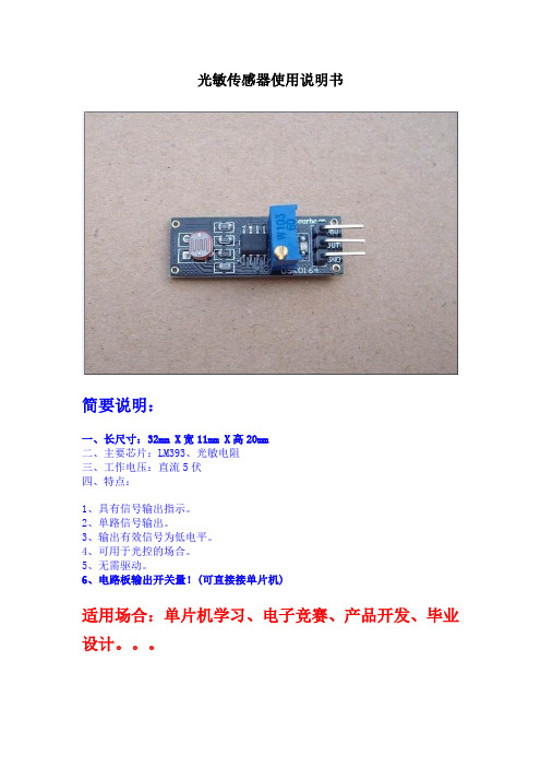
光敏传感器使用说明书简要说明:一、长尺寸:32mm X宽11mm X高20mm二、主要芯片:LM393、光敏电阻三、工作电压:直流5伏四、特点:1、具有信号输出指示。
2、单路信号输出。
3、输出有效信号为低电平。
4、可用于光控的场合。
5、无需驱动。
6、电路板输出开关量!(可直接接单片机)适用场合:单片机学习、电子竞赛、产品开发、毕业设计。
【图片展示】【与单片机连接测试程序】/********************************************************************汇诚科技实现功能:此版配套测试程序使用芯片:AT89S52晶振:11.0592MHZ波特率:9600编译环境:Keil作者:zhangxinchunleo网站:淘宝店:汇诚科技【声明】此程序仅用于学习与参考,引用请注明版权和作者信息!*********************************************************************/ /********************************************************************说明:1、当测量浓度大于设定浓度时,单片机IO口输出低电平*********************************************************************/ //使用时按复位键,传送数据更新#include<reg51.h>#include<intrins.h>#define uchar unsigned char //宏定义无符号字符型#define uint unsigned intsbit LED=P1^0; //定义单片机P1口的第1位(即P1.0)为指示端可以自己改sbit Speak =P1^1; //蜂鸣器器控制脚可以自己改不同单片机不一样sbit DOUT=P3^5; //定义单片机P2口的第1位(感器的输入端可即P2.0)为传以自己改void Delay_1ms(uint i)//1ms延时{uchar x,j;for(j=0;j<i;j++)for(x=0;x<=148;x++);}//初始化串口程序,晶振11.0592, 波特率9600void Com_Init(void){TMOD = 0x20;PCON = 0x00;SCON = 0x50;TH1 = 0xFd;TL1 = 0xFd;TR1 = 1;}void LEDFMQ(){LED=1; //熄灭P1.0口灯if(DOUT==0)//当浓度高于设定值时,执行条件函数{Delay_1ms(1);//延时抗干扰if(DOUT==0)//确定浓度高于设定值时,执行条件函数{LED=0; //点亮P1.0口灯Speak=1; // 蜂鸣器不停的响Delay_1ms(1);Speak=0;}}}void Main(){uchar p;uchar Buffer =DOUT; //接收所要发送的数据Com_Init();// P2 = 0x00;p = Buffer;while(1){LEDFMQ(); //一直检测是否达到阈值SBUF = p;while(!TI) //如果发送完毕,硬件会置位TI 复位键使用// {_nop_();// }//在每个字符串的最后,会有一个'\0'TI = 0; //TI清零}// while(1);}/********************************************************************结束*********************************************************************/。
光敏传感器 EE-SX1023-W1 产品说明书

Slot-type pre-wired model•General-purpose model with a 2.1-mm-wide slot.Model Number StructureOrdering InformationPhotomicrosensorRatings, Characteristics and Exterior SpecificationsAbsolute Maximum Ratings (Ta = 25°C )*1.Refer to the temperature rating chart if the ambient temperatureexceeds 25°C.*2.The pulse width is 10 μs maximum with a frequency of 100 Hz.*plete soldering within 10 seconds.Exterior SpecificationsElectrical and Optical Characteristics (Ta = 25°C)RoHS CompliantBe sure to read Safety Precautions on page 3.(2)(1)EE-S X 1 023 - W 1(3)(4)(5)(6)(2)Transmissive(5)Coad(4)Serial number(6)Serial number(3)Phototransistor output(1)PhotomicrosensorItemSymbol Rated valueUnit EmitterForward current I F 50 *1mA Pulse forward current I FP 1 *2A Reverse voltage V R 4V DetectorCollector-Emitter voltage V CEO 30V Emitter-Collector voltage V ECO ---V Collector current I C 20mA Collector dissipation P C100 *1mWAmbient temperatureOperating T opr -25 to 85°C StorageT stg -30 to 100°C Soldering temperatureT sol260 *3°CConnecting methodWeight (g)Material Case Pre-wired3.4PolycarbonateItemSymb olValue UnitConditionMIN.TYP.MAX.EmitterForward voltage V F --- 1.2 1.5V I F = 30 mA Reverse current I R ---0.0110μA V R = 4 V Peak emission wavelength λP---940---nmI F = 20 mADetectorLight currentI L0.5------mAI F = 20 mA,V CE = 5 V Dark currentI D ---2200nA V CE = 10 V,0 l x Leakage current I LEAK ---------------Collector-Emitter saturated voltage V CE (sat)---0.10.4V I F = 20 mA,I L = 0.1 mA Peak spectral sensitivity wavelength λP---850---nmV CE = 10 V Rising timetr ---4---μsV CC = 5 V,R L = 100 ΩI L = 5 mA Falling time tf ---4---μsV CC = 5 V,R L = 100 ΩI L = 5 mAEngineering Data (Reference value)Fig 1. Forward Current vs. Collector Dissipation Temperature RatingFig 2. Forward Current vs. Forward Voltage Characteristics (Typical)Fig 3. Light Current vs. Forward Current Characteristics (Typical)Fig 4. Light Current vs. Collector-Emitter Voltage Characteristics (Typical)Fig 5. Relative Light Current vs. Ambient Temperature Characteristics (Typical)Fig 6. Dark Current vs. Ambient Temperature Characteristics (Typical)Fig 7. Response Time vs. LoadResistance Characteristics (Typical)Fig 8. Sensing Position Characteristics (Typical)Fig 9. Response Time Measurement CircuitF o r w a r d c u r r e n t I F (m A )C o l l e c t o r d i s s i p a t i o n P c (m W )Ambient temperature T a (°C)10080604020-200-400102030405060I FP C501001500.20.40.60.811.2 1.4 1.6 1.8F o r w a r d c u r r e n t I F (m A )Forward voltage V F(V)108642L i g h t c u r r e n t I L (m A )Forward current I F (mA)L i g h t c u r r e n t I L (m A )Collector–Emitter voltage V CE (V)R e l a t i v e l i g h t c u r r e n t I (%)Ambient temperature Ta (°C)D a r k c u r r e n t I D (n A )Ambient temperature Ta (°C)R e s p o n s e t i m e t r , t f (µs )Load resistance R L (k )-0.5-0.2500.250.50.75 1.0Distance d (mm)R e l a t i v e l i g h t c u r r e n t I L (%)Input 0Output OutputSafety PrecautionsTo ensure safe operation, be sure to read and follow the Instruction Manual provided with the Sensor.This product is not designed or rated for ensuring safety of persons either directly or indirectly. Do not use it for such purposes.Do not use the product with a voltage or current that exceeds the rated range.Applying a voltage or current that is higher than the rated range may result in explosion or fire.Do not miswire such as the polarity of the power supply voltage.Otherwise the product may be damaged or it may burn.This product does not resist water. Do not use the product in places where water or oil may be sprayed onto the product.Do not use the product in atmospheres or environments that exceed product ratings.Dispose of this product as industrial waste.Dimensions and Internal Circuit(Unit: mm)PhotomicrosensorCAUTIONPrecautions for Safe UsePrecautions for Correct UseCross section A-AKA CEEE-SX1023-W1Internal circuitTerminal No.Color Name A Orange Anode K Green Cathode C White Collector EBlueEmitterUnless otherwise specified, the tolerances are as shown below.DimensionsTolerance 3 mm max.±0.2003 < mm ≤ 6±0.2406 < mm ≤ 10±0.29010 < mm ≤ 18±0.35018 < mm ≤ 30±0.42030 < mm ≤ 50±0.50050 < mm ≤ 80±0.600EmitterDetector1.3 × 0.51.3 × 0.5Aperture size (H×W)Please check each region's Terms & Conditions by region website.OMRON CorporationElectronic and Mechanical Components CompanyRegional Contactr opeAme icas Euhttps:/// http://components.omron.eu/ Asia-Pacific China https://.sg/ https:///Ko ea Japanhttps://www.omron-ecb.co.kr/ https://www.omron.co.jp/ecb/。
Token 可见光光敏电阻传感器数据手册说明书

(PT-IC-AC) Visible Light Sensor RoHSCompliantToken Electronics Industry Co., Ltd.Taiwan: No.137, Sec. 1, Zhongxing Rd., Wugu District, New Taipei City, Taiwan, R.O.C. 24872 Tel: +886 2981 0109 Fax: +886 2988 7487China: 12F, Zhong Xing Industry Bld., Chuang Ye Road, Nan Shan District, Shen Zhen City, Guang Dong, China 518054 Tel: +86 755 26055363; Fax: +86 755 26055365 Web: Email:*************.twV ersion: July 4, 2017Product IntroductionFeatures :● Simulate the human eye, peak wavelength 550nm.● Built-in infrared filter, can be anti-infrared interference.● Good batch consistency, completely solve the infrared light start too early. ● Fast response, stable performance, aging at +85°C/ 65% humidity for 1000 Hr. ● The starting point does not drift. Nice appearance.Applications :● Replace the traditional CDS photoresistor. ● Cadmium and lead free with RoHS compliant. ● Dedicated to infrared monitoring products.● When control the infrared light, it is no need to add extra casing and filter on low illumination.Customization :● For the convenience of installation in all kinds of products in any position, different sizes are available upon request.● Token offers various option of the bright current/dark current (bright resistance/dark resistance) to costume the most products.(PT-IC-AC) visible light sensor is a silicon NPN epitaxial planarphototransistor in a T-1 package. It is sensitive to visible light much like the human eye and has peak sensitivity at 520nm ~ 580nm.The spectral response of the integrated light sensor with a very low dark current that are optimized for sensing low level light signals. So it ignores light such as infrared which emits energy but does not aid vision. This eliminates the need for an Infrared filter required with competitor light sensors.The (PT-IC-AC) Plate Edge IR visible light detector using high quality chip packaging and processing super-plated infrared filter membrane on chipsurface, so this sensor can fully filter infrared interference. It is no need to add the casing and extra filter and effective filtering out the effect of light reflection due to infrared emission on security products.By selecting the accuracy of chips, under strict management of production process, (PT-IC-AC) visible light sensors finished batch consistency uniform. The consistency is 3 to 5 times higher on comparisonof similar photosensitive devices. The precision can be controlled as narrow as 10%. Fully meet the customer requirements for starting the LUX value. Token taking the advantage of temperature compensation internal process on the chip, (PT-IC-AC) features one times higher temperatureresistance than other similar products while working on high temperature environment. Please contact our sales or link to Token official website “Visible Light Sensors ” for more information.Token providing optimized light sensing solutions to enhance system efficiency and ease-of-design.Dimensions0.20 0.20 Max. 0.50 0.20 0.20 0.20 0.50Visible Light Sensor RoHS Compliant (PT-IC-AC-PE-550) DimensionsVisible Light Sensor RoHS Compliant (PT-IC-AC-PE-550)Remark:●The epoxy resin highest: 1.5mm max.●Product images, plastic color of apperence, and all other information is for reference only, goods in-kind prevail.●Short Lead—Collector Long Lead—Emitter.0.20 0.20 0.20 0.20 0.20Visible Light Sensor RoHS Compliant (PT-IC-AC-5-BN-520) Dimensions Visible Light Sensor RoHS Compliant (PT-IC-AC-5-PN-580)Remark:●The epoxy resin highest: 1.5mm max.●Product images, plastic color of apperence, and all other information is for reference only, goods in-kind prevail.●Short Lead—Collector Long Lead—Emitter.PT-IC-AC-5-PN-580 5.00 ± 0.20 5.00 ± 0.20 5.30 ± 0.20 14.0 Min. 2.00 ± 0.50 2.54 ± 0.20Visible Light Sensor RoHS Compliant (PT-IC-AC-5-PN-580) Dimensions Visible Light Sensor RoHSCompliant (PT-IC-AC-5-PN-580)Remark:●The epoxy resin highest: 1.5mm max.●Product images, plastic color of apperence, and all other information is for reference only, goods in-kind prevail.●Short Lead—Collector Long Lead—Emitter.3-PE CurveRelative Spectral Sensitivity vs. Wavelength (PT-IC-AC-3-PE-550)Photo Current vs. Illuminance (PT-IC-AC-3-PE-550)Dark Current vs. Ambient Temperature (PT-IC-AC-3-PE-550)5-PE CurveRelative Spectral Sensitivity vs. Wavelength (PT-IC-AC-5-PE-550)Photo Current vs. Illuminance (PT-IC-AC-5-PE-550)Dark Current vs. Ambient Temperature (PT-IC-AC-5-PE-550)BN CurveRelative Spectral Sensitivity vs. Wavelength (PT-IC-AC-5-BN-520)Photo Current vs. Illuminance (PT-IC-AC-5-BN-520)Dark Current vs. Ambient Temperature (PT-IC-AC-5-BN-520)PN CurveRelative Spectral Sensitivity vs. Wavelength (PT-IC-AC-5-PN-580)Photo Current vs. Illuminance (PT-IC-AC-5-PN-580)Dark Current vs. Ambient Temperature (PT-IC-AC-5-PN-580)NoteVisible Light Detector (PT-IC-AC) Precaution Usage :● The light source : Select 590nm LED Surface light source.Mounting :● While packages are on one circuit board, avoid mismatching in the thermal expansion of each component, generate cracks in the package and break the bonding wire.Soldering :● Do not immerse plastic parts in tin tank. ● During soldering, when adding thermal stress in a moistureabsorbing state, moisture evaporates, swells and generatesstress to the internal package.● To avoid swellings and cracks in the surface of the package, followsoldering conditions below.● Wave soldering method: 120°C < 60s 、260°C < 5s. ● Manual soldering: 260°C < 5s 、340°C < 3s.Lead-forming and cuttings :● Before soldering, perform lead forming at normal temperature.● While forming or cutting the lead, stay the area at a distance of 5 mm or greater from the root of the lead. ● Avoid mounting which may cause force on the root of the lead. Storage :The sensor is incorporated in the transparent resin package. Because of its sensitivity to humidity, the package is moisture-proof. When storing the sensor, do as instructed below.● Quickly use after opening. (within 2 days, below 30 °C/60 % R.H.).● Once unpacked, use within three months, or keeping within a moisture-proof method, which include maintaining within a moisture-proof container with silica gels, is suggested for longterm safe-keeping. ● Very bad storage conditions may deteriorate solderability or characteristics, and defect the appearance. Recommended conditions of the storage place, temperature 0°C to 30 °C, humidity below 60% R.H. (Avoid freezingand dew condensation).Cleaning :● Do not wash with water to avoid corrosion.● Under any circumstance, the cleaning time should be within 1 minute of normal temperature. ● Alcohol is recommended as a cleaning agent when cleaning products.● If you use other cleaning agents, you need to confirm whether the cleaning agent will corrode the epoxy body.● Freon can not be used as a cleaning agent.● When cleaning products with ultrasonic cleaning, ultrasonic power and time should be less than 300W and 30 seconds, respectively.● PCB and product can not touch the oscillator. Can not make the product on the PCB resonance. ● This model is static sensitive devices, so static electricity and surges can damage the product. ● To all the equipment, machines, tables, and the ground must be anti-static ground. ● Requires the use of anti-static wrist strap wear.Photo Current Measurement Method - (PT-IC-AC)Order Codes。
光敏传感器使用说明
BB=1;
TR1 = 0;
while(1);
}*/
}
/*if((AA==0)&(temp<=20))
{
temp = 0;
BB = 0;
}
if((AA==0)&(temp>=30))
sbit AA = P2^0;
sbit BB = P0^0;
void init()
{
TMOD = 0x11;
TH0 = (65535-50000)/256;
TL0 = (65535-50000)%256;
EA = 1;
TR0 = 1;
ET0 = 1;
TH1 = (65535-50000)/256;
//TR1 = 1;
//if((AA==0)&&(temp1==50))
//if(temp1==10)
//{
// {
if(AA==0)
// temp1 = 0;
//flag1 = 1;
BB=!BB;
}
}
//TR1=1;
// temp1= 0;
// TR1=0;
}
}
/*if(AA==1)
{
TR1 = 1;
if((AA==1)&&(temp1>=80))
{
temp1 = 0;
//flag1 = 1;
BB=1;
TR1 = 0;
while(1);
}
} */
/*else
{
if(AA==1)
光敏传感器产品说明说明书

DatasheetDiffuse or Retroreflective Sensor for Error Proofing of Bin-Picking Operations•One-component system, easy to mount and even easier to use. Automatically operates in either diffuse or retroreflective mode, depending on the application•Automatic setup and adjustment; wide beam pattern provides easy alignment•Range up to 2 m (6.5 ft) when used with retroreflective target; 400 mm (15.7 in) when used in diffuse mode •Large job lights on either side of the metal housing can be remotely controlled to initiate user action with a solid or a blinking green light; job lights turn red to indicate bin-picking errors •Compact package size; only 30 mm wide × 15 mm deep (1.2 in × 0.6 in)•Available in 2 lengths to fit existing parts bin sizes and configurations•Easy DIP-switch adjustments: PNP/NPN output, normally open/normally closed operation, solid/flashing job light, and gate polarity for job light activation •Two LEDs indicate power ON and output ON•Choose 2 m (6.5 ft) unterminated cable or 2 m (6.5 ft) cable with 5-pin Euro-style quick-disconnect connector•Heavy-duty protective brackets available •12 V dc to 30 V dc operationWARNING: Not To Be Used for Personnel ProtectionNever use this device as a sensing device for personnel protection. Doing so could lead to serious injury or death. This device does not include the self-checking redundant circuitry necessary to allow its use in personnel safety applications. A sensor failure or malfunction can cause either an energized or de-energized sensor output condition.ModelsOverviewThe PVD Series Parts Verification Sensor is a one-component, easy-to-use light screen suited to many part assembly, bin picking (pick-to-light), and error-proofing applications. The PVD increases task efficiency due to simplified job training, increased quality control (no skipped components), and reduced rework and inspections. It speeds the resumption of work after breaks and other distractions, and is ideal for multilingual workplaces where communication is an issue.The PVD self-contained, solid-state emitter/receiver array is capable of functioning in either diffuse or retroreflective sensing mode. Noconfiguration is required for this selection. If a retroreflective target is installed opposite the sensor, it will function in retroreflective mode. If not, it will function in diffuse mode. The sensor’s ongoing self-adjustment feature requires no user adjustment; the sensor adapts to the sensing conditions after 15 seconds when blocked. Sensor range decreases when no retroreflector is installed.The DIP-switch-selectable PNP/NPN output interfaces to a system controller, which is pre-programmed for a specific sequence of tasks.Mounted with its visible red beams stretching across each parts bin, the sensor job light signals the assembler which bins contain items to be picked in a given operation and in what order they should be picked.As the assembler takes a part in sequence and breaks the beam, the sensor senses that the part was removed and it sends an output signal to the controller. The controller then verifies if the correct part was taken and may respond by turning that job light OFF, activating the job light of the next bin in the sequence. If the assembler reaches into a bin out of sequence, the PVD turns on its output to signal the system controller and turns on its red job light to signal the assembler that an incorrect pick has occurred.Standard configuration options are selected by means of a bank of four DIP switches behind a press-on black rubber cover. DIP switch options include: PNP or NPN output, Normally Open or Normally Closed operation, steady or flashing job light, and job light control input.•To order the 150 mm (6 in) cable model with a quick disconnect, add the suffix "W/6IN" to the cabled model number. For example,PVD100Q W/6IN.•Models with a quick disconnect require a mating cordset.PVD Series Parts Verification SensorOriginal Document 113230 Rev. G4 August 2016113230Figure 1. Sensor features10 mm20 mm30 mm40 mm50 mm60 mm70 mm80 mm90 mm100 mm110 mm2.5 m2 m1.5 m1 m0.5 mRangeMinimumObjectSizetoAlwaysBlockaBeamFigure 2. Minimum object detection size (retroreflective operation)InstallationMultiple sensors located farther than the sensor's maximum range from one another are unlikely to cause crosstalk problems. However, when multiple sensors are mounted in a confined area, take care to avoid crosstalk between them. Alternate the relative position of adjacent sensors and/or reflectors. Sensors positioned above or below one another should not create crosstalk difficulties. Mount the sensor and reflector parallel.Figure 3. Examples of Appropriate Positions Figure 4. Example of Incorrect Position - Tel: +1-763-544-3164P/N 113230 Rev. GMountingThe wide beam pattern of PVD sensors simplifies their alignment. M4 stainless steel fasteners and two stainless steel brackets are included with each sensor.Mount the sensor and its reflector, if used, parallel to one another in the same plane, and their tops and bottoms aligned.1.From a common point of reference, make measurements to locate the sensor and itsreflector, if used, in the same plane with their midpoints directly opposite each other.2.Mount the included brackets to the top and bottom of each sensor, as shown.3.Mount the sensor in its brackets and the reflector, if used, being careful to position thesensor's red lenses directly facing the reflector.4.Measure from one or more reference planes (for example, the building or bin floor) to thesame point(s) on the emitter and receiver to verify their mechanical alignment. (If the sensors/reflectors are mounted exactly vertical or horizontal, a carpenter’s level may be helpful. A straightedge or a string extended between the sensor and the bin wall may also be helpful.)5.Also check “by eye” for line-of-sight alignment.6.Make any necessary final mechanical adjustments, and hand-tighten the bracket hardware.7.After the electrical hookup is complete, check for beam alignment. If necessary, re-align theemitter and receiver at that time.Figure 5. PVD MountingHardwareWiringAll models feature integral 2 m (6.5 ft) long, 3.3 mm (0.13 inch) diameter PVC-jacketed cables. Models whose model numbers end in “Q”are terminated with quick-disconnect (QD) Euro-style 5-pin connectors; other models have unterminated ends. Optional mating QD cables are available. Either 4-pin or 5-pin QD cables may be used; the center pin of a 5-pin cable (gray wire, pin 5) is unused in normal operation.Wiring is functionally identical for cabled and quick-disconnect models.NPN (Sinking) OutputPNP (Sourcing) OutputKey–+–+1 = Brown2 = White3 = Blue4 = Black5 = GraySee Configuration on page 3 for job light control input requirements.ConfigurationTo configure the PVD, set the DIP switches as shown, using the supplied plastic screwdriver to avoid damaging the switches or causing a short circuit.P/N 113230 Rev. G - Tel: +1-763-544-31643The switches determine four status operating modes:Status Indicators/Troubleshooting - Tel: +1-763-544-3164P/N 113230 Rev. GSpecificationsSupply Voltage and CurrentInput Voltage: 12 V dc to 30 V dc (10% maximum ripple at 10% duty cycle)Input Current: less than 88 mA at 12 V dc, less than 75 mA at 24 V dc and less than 72 mA at 30 V dc (exclusive of load)Supply Protection CircuitryProtected against reverse polarity and transient overvoltages Sensing BeamVisible red, 630 nmSensing RangeRetroreflective applications: 2 m (6.5 ft) using 25 mm (1 in) wide retroreflective tapeDiffuse applications: 400 mm (15.7 in) with 18% reflectivity gray card target Sensing Height4-channel models: 111 mm (4.4 in)8-channel models: 240 mm (9.4 in)Beam Spacing28.6 mm (1.125 in)Output ConfigurationUser-selectable via DIP switch:1 open-collector PNP (current sourcing) or 1 open-collector NPN (current sinking)Output Rating150 mA maximumOFF-state leakage current: less than 10 microampsON-state saturation voltage: NPN — less than 1 V dc at 150 mA; PNP — less than 2 V dc at 150 mARequired Overcurrent ProtectionWARNING: Electrical connections must be made by qualified personnel in accordance with local and national electrical codes and regulations.Overcurrent protection is required to be provided by end product application per the supplied table.Overcurrent protection may be provided with external fusing or via Current Limiting, Class 2 Power Supply.Supply wiring leads < 24 AWG shall not be spliced.For additional product support, go to .Output ProtectionProtected against false pulse on power-up and short circuit of outputs Output Response Time400 ms (includes standard 100 ms ON-delay and 100 ms OFF-delay)Delay at Power-UpLess than 1.0 secondSensing ResolutionSee Dimensions on page 6 for Minimum Object Detection ZoneRetroreflective: 51 mm at 406 mm range, 100 mm at 2 m (2.0 in dia. at 16 in range, 3.9 in at 6.5 ft); see Figure 2 on page 2Diffuse: 55 mm dia. at 400 mm range (2.16 in at 15.7 in range)IndicatorsGreen LED: Power ON/OFF Yellow LED: Output ON/OFFJob Light (Diffused Green LED): Turned ON and OFF by applying an external signal to the Job input (white wire). The job lights will be active high or active low, depending on DIP switch 4 selection.Error Light (Diffused Red LED): Turned ON and OFF by detection of an output event when job light is not ON.Indicator Light LumensAdjustments4 DIP switches, located behind access panel (default setting is ON position)ConstructionBlack painted aluminum housing; acrylic lenses; thermoplastic polyester end caps; thermoplastic elastomer programming switch cover; stainless steel mounting brackets and hardware Connections5-conductor PVC-jacketed 2 m (6.5 ft) cable which is either unterminated or terminated with a 5-pin Euro-style quick-disconnect connector, depending on model. Cable diameter is 3.3 mm (0.13 in).Environmental RatingNEMA 2; IEC IEC IP62Operating ConditionsTemperature: 0 °C to +50 °C (+32 °F to +122 °F)Humidity: 90% at +50 °C maximum relative humidity (non-condensing)CertificationsP/N 113230 Rev. G - Tel: +1-763-544-31645Dimensions4 x ø4.45 mm (0.175")Cable3.9 mm (0.15")3.9 mm (0.15")1.4 mm SMBPVA1 Standard Bracket (2 Included with PVD)Hardware Included with Each Sensor (kit part number 50532)4 x ø4.6 mm2.0 mm (0.08")10.2 mm (0.40") - Tel: +1-763-544-3164P/N 113230 Rev. GAccessoriesCordsetsBracketsAll measurements are listed in millimeters, unless noted otherwise.Bracket Selection TableNOTE: Standard mounting brackets are included with each PVD System. The following brackets are in addition to the standard brackets.P/N 113230 Rev. G - Tel: +1-763-544-31647Retroreflective TapeBanner Engineering Corp. Limited WarrantyBanner Engineering Corp. warrants its products to be free from defects in material and workmanship for one year following the date of shipment. Banner Engineering Corp. will repair or replace, free of charge, any product of its manufacture which, at the time it is returned to the factory, is found to have been defective during the warranty period. This warranty does not cover damage or liability for misuse, abuse, or the improper application or installation of the Banner product.THIS LIMITED WARRANTY IS EXCLUSIVE AND IN LIEU OF ALL OTHER WARRANTIES WHETHER EXPRESS OR IMPLIED (INCLUDING, WITHOUT LIMITATION, ANY WARRANTY OF MERCHANTABILITY OR FITNESS FOR A PARTICULAR PURPOSE), AND WHETHER ARISING UNDER COURSE OF PERFORMANCE, COURSE OF DEALING OR TRADE USAGE.This Warranty is exclusive and limited to repair or, at the discretion of Banner Engineering Corp., replacement. IN NO EVENT SHALL BANNER ENGINEERING CORP. BE LIABLE TO BUYER OR ANY OTHER PERSON OR ENTITY FOR ANY EXTRA COSTS, EXPENSES, LOSSES, LOSS OF PROFITS, OR ANY INCIDENTAL, CONSEQUENTIAL OR SPECIAL DAMAGES RESULTING FROM ANY PRODUCT DEFECT OR FROM THE USE OR INABILITY TO USE THE PRODUCT, WHETHER ARISING IN CONTRACT OR WARRANTY, STATUTE, TORT, STRICT LIABILITY, NEGLIGENCE, OR OTHERWISE.Banner Engineering Corp. reserves the right to change, modify or improve the design of the product without assuming any obligations or liabilities relating to any product previously manufactured by Banner Engineering Corp.Copyright NoticeAny misuse, abuse, or improper application or installation of this product or use of the product for personal protection applications when the product is identified as not intended for such purposes will void the product warranty. Any modifications to this product without prior express approval by Banner Engineering Corp will void the product warranties. All specifications published in this document are subject to change; Banner reserves the right to modify product specifications or update documentation at any time. For the most recent version of any documentation, refer to: . © Banner Engineering Corp. All rights reserved. - Tel: +1-763-544-3164。
Banner Engineering光敏传感器系列产品说明书

Datasheet•Modular design for easy exchange of all sensing components and wiring logic •Interchangeable AC or DC power blocks•Opposed, polarized and non-polarized retroreflective, diffuse, convergent, fixed-field, and glass or plastic fiber optic sensing modes available•Interchangeable sensing heads with 90° increment rotation •Optional output timing logic modules with programming ring •Quad-ring sealed components resist dirt, dust, and moisture•Banner Engineering's Alignment Indicating Device (AID) for indication of signal strength •15-turn potentiometer for manual adjustment of sensitivity •Range up to 90 m•Logic modules offer ON-delay, OFF-delay, ON/OFF-delay, One Shot, and Delayed One Shot output switching logic, depending on model•Logic modules also offer 0.01 s to 1 s, 0.5 s to 15 s, or 0.1 s to 1 s delay, depending on model•Power blocks plug into required RWB4 wiring base and feature two LED indicators foroutput and input statusWARNING:•Do not use this device for personnel protection•Using this device for personnel protection could result in serious injury or death.•This device does not include the self-checking redundant circuitry necessary to allow its use inpersonnel safety applications. A device failure or malfunction can cause either an energized (on) or de-energized (off) output condition.OverviewBanner MAXI-BEAM ® sensors are highly versatile, self-contained, modularized photoelectric sensing controls that are ideally suited to industrial environments. The basic MAXI-BEAM is an ON/OFF switch consisting of three modules (sensor head,power block, and wiring base) and a unique, patented, rotatable programming ring that enables you to program your choice of light or dark operate mode, sensing range, and response time.MAXI-BEAM sensor heads have an easily-accessible multi-turn sensitivity control for precise adjustment of system gain. Interchangeable sensor heads are rotatable in 90-degree increments and are available in retroreflective, diffuse, opposed,convergent, fixed-field proximity, and fiberoptic sensing modes. Each sensor head also includes Banner's exclusive, patented AID ™ circuit (Alignment Indicating Device, US Patent no. 4356393), which features an LED alignment indicator that lights whenever the sensor sees its own modulated light source, and pulses at a rate proportional to the strength of the received light signal.A wide selection of MAXI-BEAM power block modules is available to interface the sensor head to the circuit to be controlled. The plug-in design of the wiring base enables easy exchange of the entire sensing electronics without disturbing field wiring.Optional customer-installable logic modules easily convert the basic ON/OFF MAXI-BEAM into either a one-shot or delay logic function control, with several programmable timing ranges for each function.MAXI-BEAM sensors are ruggedly constructed of molded PBT to NEMA standards 1, 3, 4, 12, and 13, and have interchangeable molded acrylic lenses. Modulessimply snap and bolt together, with no interwiring necessary. Module interfaces areo-ring and quad-ring sealed for the ultimate in dust, dirt, and moisture resistance.Rotatable Sensor Head Programming RingLogic Module (optional)Programming Ring for LogicRWB4Wiring Base Power Block Conduit EnteranceMAXI-BEAM Opposed Mode Emitter (E) and Receiver (R)MAXI-BEAM emitters have a visible red "tracer beam". This beam is non-active, and is used as a means of visual alignment during installation. A retroreflector temporarily attached to the receiver lens provides aneffective target for the tracer beam during alignment. The narrow beam of the RSBESR/RSBRSR pair is ideal for sensing small parts (effective beam diameter is 3.6 mm (0.14 in).One emitter and one receiver are required for use.MAXI-BEAM ® Sensor HeadsOriginal Document 03416 Rev. H2 March 2022034163.3 ft 33 ft 330 ft0.33 ftE X C E S S G A I NDISTANCE 400 ft320 ft 240 ft 160 ft 80 ft 0125 mm 250 mm 375 mm125 mm250 mm375 mm 05 in 10 in 15 in5 in 10 in 15 in DISTANCE0.33 ft 3.3 ft 33 ft0.033 ftEX C E S S G A I NDISTANCE15 ft12 ft 9 ft 6 ft 3 ft 0200 mm 400 mm600 mm200 mm400 mm600 mm 08 in 16 in 24 in8 in16 in 24 in DISTANCEMAXI-BEAM Opposed Fiber Optic Mode (Glass Fibers)This sensor pair is designed for opposed mode operation using Banner glass fiber optics. Maximum range (HP mode) using L9 lenses is 12 feet. Maximum range using L16F lenses is 50 feet. One emitter and one receiver are required for use..40 in 4.0 in 40 in.04 inE X C E S S G AI NDISTANCE40 in32 in 24 in16 in8 in50 mm 100 mm 150 mm50 mm100 mm 150 mm02 in 4 in6 in2 in4 in 6 in DISTANCE - Tel: + 1 888 373 6767P/N 03416 Rev. H.33 ft 3.3 ft 33 ft.033 ftE X C E S S G A I NDISTANCE050 mm 100 mm 150 mm50 mm100 mm150 mm 02.0 in4.0 in 6.0 in2.0 in 4.0 in 6.0 in DISTANCE33 ft26 ft 20 ft 13 ft 6.6 ft.33 ft 3.3 ft 33 ft.033 ftE X C E S S G A I NDISTANCE025 mm 50 mm75 mm25 mm50 mm 75 mm 01.0 in2.0 in3.0 in1.0 in2.0 in3.0 in DISTANCE16 ft13 ft 10 ft 6.6 ft 3.3 ft0.33 ft 3.3 ft 33 ft0.033 ftE X C E S S G A I NDISTANCE 025 mm 50 mm 75 mm25 mm50 mm 75 mm 01.0 in 2.0 in 3.0 in1.0 in2.0 in3.0 in DISTANCE 5 ft4 ft 3 ft 2 ft 1 ft 0.4 in 4.0 in 40 in0.04 inE X C E S S G A I NDISTANCE 012.5 mm 25.0 mm 37.5 mm12.5 mm25.0 mm 37.5 mm 00.5 in 1.0 in 1.5 in0.5 in1.0 in 1.5 in DISTANCE30 in 24 in18 in 12 in6 inConvergent ModeRSBC: Powerful infrared beam reliably senses objects of low reflectivity. Ideal for counting the flow of radiusedproducts at a fixed distance from the sensor.RSBCV: Powerful visible red beam with precise .06 inch diameter sensing spot. Useful in many high-contrast color registration applications.0.4 in 4.0 in 40 in0.04 inE X C E S S G A I NDISTANCE 02.5 mm5.0 mm 00.1 in2.5 mm0.1 in 0.2 in 5.0 mm0.2 inDISTANCE .4 in 4 in 40 in.04 inE X C E S S G A I NDISTANCE 2.5 in2.0 in 1.5 in 1.0 in 0.50 in 00.8 mm 1.6 mm 2.4 mm0.8 mm1.6 mm2.4 mm 00.03 in 0.06 in 0.09 in0.03 in 0.06 in 0.09 in DISTANCEP/N 03416 Rev. H - Tel: + 1 888 373 67673Fixed-Field ModeFixed-field sensor heads have an emitter element and two differently-aimedreceiver elements. This creates a high-gain sensing field able to detect objects of low reflectivity, and a sharp far-limit sensing cutoff of 50mm (2 inches) or 100mm (4 inches) which ignores backgrounds beyond cutoff.These sensors are ideal for detecting a part or surface that is only a fraction of an inch in front of another surface.RSBFFs may not be used with 2-wire power blocks.1000100E X C E S S GIDISTANCEFiber Optic Mode (Glass Fibers)Note: If the retroreflective sensing mode is used in conjunction with the HP or 2Wprogram mode, the GAIN control must be reduced from the factory setting to avoid optical feedback from the lens assembly.For information on the complete line of Banner glass fiber optics, go to .0.4 in 4.0 in 40 in0.04 inE X C E S S G A I NDISTANCE40 in32 in 24 in 16 in 8 in 050 mm 100 mm 150 mm50 mm100 mm150 mm 02 in 4 in 6 in2 in4 in 6 in DISTANCE10DISTANCE1001000.1 FT1 FT 10 FT100 FTE X C E S S G A I NI 0I N C H E S DISTANCE TO REFLECTOR0.4 in 4.0 in 40 in0.04 inE X C E S S G A I NDISTANCE02.5 mm5.0 mm 00.1 in2.5 mm 0.1 in 0.2 in 7.5 mm0.3 in7.5 mm 0.3 in 5.0 mm0.2 in DISTANCE5 in4 in 3 in 2 in 1 in Fiber Optic ModeModel RSBFP is a visible-light sensor head designed for use with plastic fiber optics. It is compatible with allstandard Banner plastic fiber optic assemblies (see Banner product catalog). In order to function properly, the RSBFP must be programmed for the "HS" response mode. The RSBFP is not for use with glass fiber optics (instead use model RSBF or RSBFV). The model RSBFP will function only when programmed for the "HS"response mode. The model RSBFP will not operate with 2-wire power blocks (models R2PBA and R2PBB).For information on the complete line of Banner plastic fiber optics, go to . - Tel: + 1 888 373 6767P/N 03416 Rev. H.40 in 4.0 in 40 in.04 inE X C E S S G A I NDISTANCE5 in4 in 3 in 2 in 1 in 015 mm 30 mm 45 mm15 mm30 mm 45 mm 00.6 in 1.2 in 1.8 in0.6 in1.2 in 1.8 in DISTANCE0.4 in4.0 in0.004 in0.04 inE X C E S S G A I NDISTANCE01.25 mm2.50 mm3.75 mm1.25 mm2.50 mm3.75 mm 0.05 in .10 in .15 in.05 in.10 in .15 in DISTANCEFiber Optic Models (Glass Fiber, Visible Sensing Beam)The model RSBFV will function only when programmed for the "HS" response mode. The model RSBFV willnot operate with 2-wire power blocks (models R2PBA and R2PBB). Model RSBFV is a visible-light sensor head designed for use with glass fiber optics. It is compatible with all standard Banner glass fiber opticassemblies (see ). To function properly, the RSBFV must be programmed for the "HS" response mode. The RSBFV is not for use with plastic fiber optics (instead use RSBFP). For information on the complete line of Banner glass fiber optics, go to ..40 in 4.0 in 40 in.04 inE X C E S S G A I NDISTANCE10 in8 in 6 in 4 in 2 in 025 mm 50 mm 75 mm25 mm50 mm 75 mm 01 in 2 in 3 in1 in2 in3 in DISTANCE.04 in.40 in4 in.004 inEX C E S S G A I NDISTANCE1.0 in0.8 in0.6 in0.4 in0.2 in00.65 mm 1.30 mm1.95 mm0.65 mm1.30 mm 1.95 mm 00.025 in 0.050 in 0.075 in0.025 in0.050 in 0.075 in DISTANCEP/N 03416 Rev. H - Tel: + 1 888 373 67675Program the Sensor HeadProgram MAXI-BEAM sensor heads for sensor response time (and range) and for LIGHT/DARK operate. Each sensor head is supplied with a programming ring which attaches below the sensorhead by a system of pegs. There are four programming notches around the perimeter ofthe ring. To program the sensor head, find the notch that will align with the desired program combination (see figure).Note: The programming ring may have to be turned upside-down toalign the notch with the program.If LIGHT OPERATE is selected, the MAXI-BEAM output will energize on a dark-to-light transition. If DARK OPERATE is selected, the MAXI BEAM output will energize on alight-to-dark transition. In the illustration, the MAXI-BEAM is set for high speed (HS) operation in the LIGHT OPERATE output state. See the information about each individual sensor head for the response time and range associated with each setting (HP, 2W, HS, SP).Note: When programming the RSBE, RSBSER, or RSBEF emitter,select the mode that is programmed for the receiver. EXCEPTION:If the receiver is programmed for the 2-wire (2W) mode, select highpower (HP) on the emitter.Figure 1. Sensor Head and Programming RingSensor Head SpecificationsSensitivity Adjustment15-turn clutched controlEasily accessible, located on top of the sensor head beneath a watertight gasketed screw-coverRotate clockwise to increase sensitivityAlignment IndicatorRed LED on top of sensor head. Banner's exclusive AID™ circuit1 lights the LED whenever the sensor sees its own modulated light source, and pulses the LED at a rate proportional to the strength of the received light signal ConstructionReinforced molded PBT housing, molded acrylic lenses, o-ring and quad-ring gasketed components. Electronic components are fully epoxy encapsulated. Environmental RatingNEMA 1, 3, 4, 12, and 13.Operating Temperature–40 °C to +70 °C (–40 °F to +158 °F)False Pulse Suppression on Power-up100 ms delay on power-upResponse Time and RepeatabilitySee models tables. The response time and repeatability are independent of signal strength.CertificationsBanner EngineeringEurope Park Lane,Culliganlaan 2F bus 3, 1831Diegem, BELGIUMTurck Banner LTDBlenheim House, BlenheimCourt, Wickford, EssexSS11 8YT, Great BritainRequired Overcurrent ProtectionWARNING: Electrical connections must bemade by qualified personnel in accordance withlocal and national electrical codes andregulations.Overcurrent protection is required to be provided by end product applicationper the supplied table.Overcurrent protection may be provided with external fusing or via CurrentLimiting, Class 2 Power Supply.Supply wiring leads < 24 AWG shall not be spliced. - Tel: + 1 888 373 6767P/N 03416 Rev. HDimensionsAll measurements are listed in millimeters, unless noted otherwise.Figure 2. Dimensions for the C-CV-D-E-R-LV modelsDIMENSION"A"CONFIGURATION WITHOUT LOGIC MODULE DIMENSION"B"114mm [4.5"]100mm [3.9"]WITH LOGIC MODULE127mm [5.0"]112mm [4.4"]"AID" ALIGNMENTINDICATORACCESS TO SENSITIVITY CONTROLFigure 3. Dimensions for the FF modelsDIMENSION"A"CONFIGURATION WITHOUT LOGIC MODULE DIMENSION"B"114mm [4.5"]100mm [3.9"]WITH LOGIC MODULE127mm [5.0"]112mm [4.4"]"AID" ALIGNMENTINDICATORACCESS TO SENSITIVITY CONTROLP/N 03416 Rev. H - Tel: + 1 888 373 67677Figure 4. Dimensions for the fiber modelsDIMENSION"A"CONFIGURATION WITHOUT LOGIC MODULE DIMENSION"B"114mm [4.5"]100mm [3.9"]WITH LOGIC MODULE127mm [5.0"]112mm [4.4"]"AID" ALIGNMENTINDICATORACCESS TO SENSITIVITY CONTROLSchematicsFigure 5. Functional SchematicFigure 6. Composite Functional SchematicRWB4Ordering InformationTo order a MAXI-BEAM, follow these steps: - Tel: + 1 888 373 6767P/N 03416 Rev. H1.Select a sensor head module.2.Select a power block module.3.Select a wiring base. The wiring base is purchased separately from the power block.4.Select a logic module (if needed).5.Select accessories as needed (see ).Sensor Head ModelsSensor head modules are described in datasheet p/n 03416.Power Block Module ModelsPower Block modules are described in datasheet p/n 03418.Wiring Base ModelsLogic Module ModelsP/N 03416 Rev. H - Tel: + 1 888 373 67679Banner Engineering Corp. Limited WarrantyBanner Engineering Corp. warrants its products to be free from defects in material and workmanship for one year following the date of shipment. Banner Engineering Corp. will repair or replace, free of charge, any product of its manufacture which, at the time it is returned to the factory, is found to have been defective during the warranty period. This warranty does not cover damage or liability for misuse, abuse, or the improper application or installation of the Banner product.THIS LIMITED WARRANTY IS EXCLUSIVE AND IN LIEU OF ALL OTHER WARRANTIES WHETHER EXPRESS OR IMPLIED (INCLUDING, WITHOUT LIMITATION, ANY WARRANTY OF MERCHANTABILITY OR FITNESS FOR A PARTICULAR PURPOSE), AND WHETHER ARISING UNDER COURSE OF PERFORMANCE, COURSE OF DEALING OR TRADE USAGE.This Warranty is exclusive and limited to repair or, at the discretion of Banner Engineering Corp., replacement. IN NO EVENT SHALL BANNER ENGINEERING CORP. BE LIABLE TO BUYER OR ANY OTHER PERSON OR ENTITY FOR ANY EXTRA COSTS, EXPENSES, LOSSES, LOSS OF PROFITS, OR ANY INCIDENTAL, CONSEQUENTIAL OR SPECIAL DAMAGES RESULTING FROM ANY PRODUCT DEFECT OR FROM THE USE OR INABILITY TO USE THE PRODUCT, WHETHER ARISING IN CONTRACT OR WARRANTY, STATUTE, TORT, STRICT LIABILITY, NEGLIGENCE, OR OTHERWISE.Banner Engineering Corp. reserves the right to change, modify or improve the design of the product without assuming any obligations or liabilities relating to any product previously manufactured by Banner Engineering Corp. Any misuse, abuse, or improper application or installation of this product or use of the product for personal protection applications when the product is identified as not intended for such purposes will void the product warranty. Any modifications to this product without prior express approval by Banner Engineering Corp will void the product warranties. All specifications published in this document are subject to change; Banner reserves the right to modify product specifications or update documentation at any time. Specifications and product information in English supersede that which is provided in any other language. For the most recent version of any documentation, refer to:.For patent information, see /patents.© Banner Engineering Corp. All rights reserved。
光敏传感器的用法 -回复

光敏传感器的用法-回复光敏传感器是一种能够监测和测量光线强度的电子设备。
它可以转换光信号为电信号,常用于自动光控系统、光源亮度调节、无人机的导航、照明设备等各种应用领域。
本文将详细介绍光敏传感器的原理、结构、使用方法以及应用案例。
一、光敏传感器的原理光敏传感器的原理基于内部的光电效应。
当光线照射到光敏传感器的光敏元件上时,光子会与光敏元件中的电子相互作用。
这个相互作用将导致电子的能级发生变化,从而产生一个电流。
传感器内部的电子元件将捕获和测量这个电流,并将其转换为电信号输出。
二、光敏传感器的结构光敏传感器通常由光敏元件、前端电路和信号处理器组成。
光敏元件是最核心的部分,其材料选择和结构设计直接影响传感器的性能。
常见的光敏元件包括光敏电阻、光敏二极管和光敏三极管等。
前端电路用于放大、滤波和处理原始的电信号,以提高传感器的灵敏度和响应速度。
信号处理器将电信号转换为数字信号,并进行进一步处理和分析。
三、光敏传感器的使用方法1. 连接电路:将光敏传感器与电路板或控制系统连接。
通常需要使用导线将传感器的引脚与电路板上的相应引脚连接起来。
2. 程序编写:根据具体应用的需求,编写相应的程序来控制光敏传感器的工作。
可以使用不同的编程语言和开发环境,如C语言、Arduino或树莓派。
3. 测试和校准:在使用光敏传感器之前,需要进行测试和校准来确保其准确性和稳定性。
可以使用标准光源、光强度计等工具来进行测试和校准。
四、光敏传感器的应用案例1. 自动光控系统:光敏传感器可以在室内或室外环境中监测光线强度,并根据实时的光强度数据来调节照明设备的亮度。
2. 光源亮度调节:光敏传感器可以实现对光源亮度的自动调节,例如车辆前照灯的自动调光功能。
3. 无人机的导航:光敏传感器可以用于无人机的导航系统,以测量周围环境的光照强度,帮助无人机定位和避开障碍物。
4. 心率检测:光敏传感器也可以用于测量人体的心率。
通过将光敏传感器放置在皮肤上,并利用血脉的脉搏特征,可以准确测量心率。
光敏传感器使用手册

光敏传感器使用手册一、引言光敏传感器是一种能够检测环境光强度的设备,它能够在光照条件发生变化时提供准确的反馈。
本手册将介绍光敏传感器的基本知识,包括使用前的准备、安装、操作方法以及常见问题的解决方法。
二、光敏传感器的工作原理光敏传感器通过感测外界环境中的光照强度来实现其功能。
它通常由光敏电阻器和一个预先调整好的电路组成。
光敏电阻器可以根据光照强度的变化来改变其电阻值,从而反映出光强度的变化。
使用者可以通过读取光敏传感器输出的电压值或电阻值来得知当前环境的光照强度。
三、使用前的准备工作1. 材料清单:- 光敏传感器- 接线材料- 开发板或者控制器- 手册/说明书2. 检查设备:在开始使用光敏传感器之前,确保所有设备完好无损。
检查电路连接是否牢固,同时检查光敏传感器表面是否有污垢或损伤。
3. 学习相关知识:在使用光敏传感器之前,建议学习一些关于传感器的知识,包括电路连接、编程和数据处理等方面的知识。
四、光敏传感器的安装在安装光敏传感器时,应注意以下几点:1. 安装位置:光敏传感器应当安装在需要检测光照强度的位置。
避免将传感器安装在有遮挡物的地方,以免影响光照强度的准确检测。
2. 保护传感器:在安装传感器时,应注意保护传感器不受到外界物体的碰撞和损坏。
可以使用适当的外壳或支架来增强传感器的保护。
3. 连接设备:在将光敏传感器连接到控制器或开发板时,确保电路连接正确无误。
五、操作方法下面是使用光敏传感器的基本操作方法:1. 连接传感器:将光敏传感器的引脚正确连接到控制器或开发板的相应引脚上。
2. 设置参数:根据需要,可以通过编程设置光敏传感器的相关参数,如灵敏度等。
3. 读取数据:使用合适的编程语言或开发平台,编写程序以读取光敏传感器输出的数据。
一般来说,可以通过读取传感器输出的模拟电压值或电阻值来得知光照强度。
4. 数据处理:根据需要,可以对传感器输出的数据进行进一步处理,如转换为光照强度的百分比或某种特定的单位。
光敏电阻传感器模块介绍
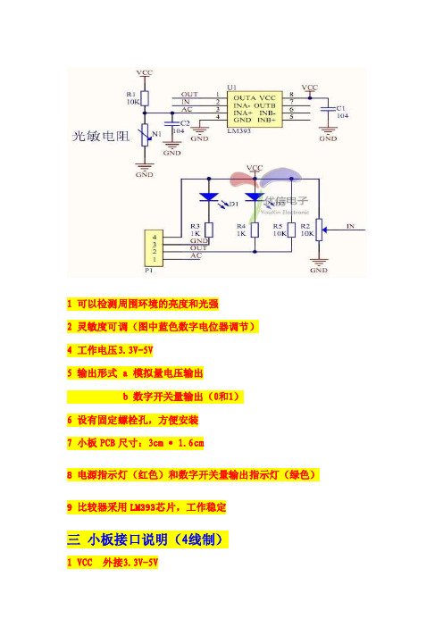
1 可以检测周围环境的亮度和光强
2 灵敏度可调(图中蓝色数字电位器调节)
4 工作电压3.3V-5V
5 输出形式 a 模拟量电压输出
b 数字开关量输出(0和1)
6 设有固定螺栓孔,方便安装
7 小板PCB尺寸:3cm * 1.6cm
8 电源指示灯(红色)和数字开关量输出指示灯(绿色)
9 比较器采用LM393芯片,工作稳定
三小板接口说明(4线制)
1 VCC 外接3.3V-5V
2 GND 外接GND
3 DO 小板数字量输出接口(0和1)
4 AO 小板模拟量输出接口
四使用说明
1光敏电阻模块对环境光强最敏感,一般用来检测周围环境的亮度和光强。
2模块在无光条件或者光强达不到设定阈值时,DO口输出高电平,当外界环境光强超过设定阈值时,模块D0输出低电平;
3小板数字量输出D0可以与单片机直接相连,通过单片机来检测高低电平,由此来检测环境的光强改变;
4小板数字量输出DO可以直接驱动本店继电器模块,由此可以组成一个光电开关;
5小板模拟量输出AO可以和AD模块相连,通过AD转换,可以获得环境光强更精准的数值;。
光敏传感器功能和使用方法

光敏传感器功能和使用方法一、什么是光敏传感器?光敏传感器,听起来是不是有点高大上?其实它就是一种能够感应光线变化的设备。
简单说,光敏传感器就是个“光线侦探”,它能像眼睛一样感知周围的亮度变化。
你想想,手机屏幕为什么会在阳光下自动调节亮度,就是靠这种小家伙在背后默默地工作。
它最常见的用途就是根据周围光线的强弱,自动调整某些设备的状态,像自动开关灯、调节显示器亮度、控制窗帘开关等等,啥都能做。
不得不说,这种东西不仅高效而且环保,省电又省心。
二、光敏传感器怎么使用?咱们聊聊光敏传感器到底怎么用吧。
它并不复杂。
想象一下,你的房间里有一个自动感应的灯,白天它亮度适中,晚上它自动亮起,简直就像是家里有了个“隐形管家”。
光敏传感器的使用大多数情况下就是接入电路里,然后它的任务就是“观察”光线的强弱。
你可能会问,怎么判断它何时开灯、何时关灯?这个原理其实很简单。
传感器会根据光线强度的变化来做决策。
当周围的光线变暗,光敏传感器就会“觉得”现在应该开灯了;而当周围光线充足时,传感器则判断可以关灯了。
简单吧,自动化生活就这么轻松。
真正的魔法可不止这些。
你可以把这种传感器安装在自动窗帘里,白天阳光足,窗帘自动拉开;夜晚阳光没了,窗帘悄悄地合上。
更厉害的是,光敏传感器还能和家里的智能设备互联互通,跟手机、电脑都能搭配使用。
你只需要把它安装好,然后设定你希望它如何反应,它就能根据你设定的条件来自动做决定,省去了一大堆麻烦。
简直就是懒人必备神器啊!三、光敏传感器的优势和应用场景光敏传感器的优势真的是数不胜数。
它能让生活更加智能化,减少人力的干预。
早上阳光透过窗帘照进来,窗帘自动拉开,你还要干嘛?在家轻松躺着,窗帘都替你搞定;下班回家,楼道的灯光亮了,你走过去,它自己又熄灭。
省心得不行,节省的时间和精力都能用来做其他事。
而且它还非常节能,毕竟灯光、空调、窗帘的开关都能智能化,啥都不用动,电能的浪费大大减少。
你知道现在的环保有多重要吗?光敏传感器帮助你做到了一举两得,既享受智能化生活,又能节省能源。
光敏传感器的用法 -回复

光敏传感器的用法-回复标题:光敏传感器的用法详解光敏传感器,作为一种能够感知光线强度变化的电子设备,广泛应用于各种环境监测、自动化控制、安全防护等领域。
本文将详细解析光敏传感器的用法,从基础概念、工作原理、选型指南到实际应用步骤,一步一步带你深入了解光敏传感器。
一、基础概念光敏传感器,又称光探测器或光电传感器,其核心功能是将接收到的光信号转化为电信号。
根据其响应波长和转换机制的不同,光敏传感器可分为光导管、光电池、光电二极管、光电三极管、光敏电阻等多种类型。
二、工作原理光敏传感器的工作原理主要是利用光电效应。
当光线照射到光敏材料上时,材料内部的电子会吸收光能并跃迁到导带,形成自由电子-空穴对,从而产生电流。
这种电流的大小与入射光的强度成正比,通过测量电流的大小,就可以得知光线的强度。
三、选型指南选择光敏传感器时,应考虑以下因素:1. 测量范围:根据应用需求,选择适合的测量范围。
例如,如果需要测量微弱的光线,应选择灵敏度高的光敏传感器。
2. 响应速度:响应速度决定了传感器对光线变化的反应速度。
对于需要快速响应的场合,应选择响应速度快的传感器。
3. 稳定性:稳定性是指传感器在长时间工作后的性能变化。
稳定性好的传感器,其测量结果更准确可靠。
4. 环境适应性:考虑使用环境的温度、湿度、光照条件等因素,选择具有相应环境适应性的传感器。
四、实际应用步骤以下是一般的光敏传感器使用步骤:1. 确定应用场景:明确光敏传感器的应用目标和环境条件,如光照强度、测量范围、响应速度等。
2. 选择合适的光敏传感器:根据上述选型指南,选择适合的光敏传感器型号。
3. 连接电路:将光敏传感器连接到相应的电路中,通常包括电源、信号处理电路和输出显示设备。
4. 校准传感器:在实际使用前,需要对光敏传感器进行校准,以确保其测量结果的准确性。
可以通过调整电路参数或者使用标准光源进行校准。
5. 测试和调试:在实际环境中测试光敏传感器的性能,如测量精度、稳定性、响应速度等,并根据测试结果进行必要的调试和优化。
PD30CNB20 光敏传感器说明书
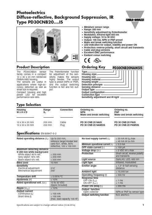
Specifications are subject to change without notice (13.06.2016)1Product Description The PD30CNB20 sensor family comes in a compact 10 x 30 x 20 mm reinforced PMMA/ABS housing. The sensors are useful in applications where high-ac-curacy detection as well as small size is required. Compact housing and high power LED for excellent performance-size ratio.The Potentiometer function for adjustment of the sen-sitivity makes the sensors highly flexible. The output type is preset (NPN or PNP), and the output switching function is NO and NC out-put.• Miniature sensor range • Range: 200 mm• Sensitivity adjustment by Potentiometer • Modulated, infrared light 850 nm • Supply voltage: 10 to 30 VDC• Output: 100 mA, NPN or PNP preset • Make and break switching function• LED indication for output, stability and power ON• Protection: reverse polarity, short circuit and transients • Cable and plug versions • Excellent EMC performance • Exellent colour matchingPhotoelectricsDiffuse-reflective, Background Suppression, IR Type PD30CNB20....ISType SelectionHousing Range Connection Ordering no.Ordering no. W x H x D S n NPNPNPMake and break switching Make and break switching10 x 30 x 20 mm 200 mm Cable PD 30 CNB 20 NAIS PD 30 CNB 20 PAIS 10 x 30 x 20 mm200 mmPlugPD 30 CNB 20 NAM5ISPD 30 CNB 20 PAM5ISSpecificationsEN 60947-5-22Specifications are subject to change without notice (13.06.2016)PD30CNB20....ISSpecifications (cont.)Operation DiagramPower supply ObjectOFF ONPresent Break Output (N.C.)Make Output (N.O.)OFF ONOFFONTv = Power ON delaySensing ConditionsDetection Diagram0,02,03,95,97,89,8Distance (Inches)-0,10-0,08-0,06-0,04-0,020,000,020,040,060,080,10(I n c h e s )050100150200250Distance (mm)-2,5-2,0-1,5-1,0-0,50,00,51,01,52,02,5(m m )Specifications are subject to change without notice (13.06.2016)3Delivery Contents• Photoelectric switch: PD30CNB20 ...• Screwdriver• Packaging: Plastic bagPD30CNB20....ISDimensionsInstallation HintsWiring DiagramsAccessories• Mounting bracket APD30-MB1 or APD30-MB2 to be purchased separately.。
Turck Q45AD9LP 红外光学光敏传感器说明书
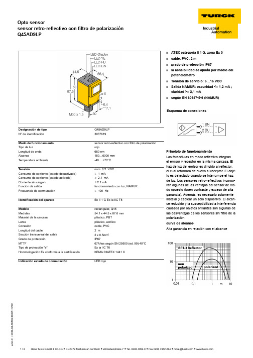
T 02:40:08+02:00Designación de tipo Q45AD9LP N° de identificación 3037619Modo de funcionamiento sensor retro-reflectivo con filtro de polarización Tipo de luzrojo Longitud de onda 680 nmAlcance150…6000 mm Temperatura ambiente-40… +70°CTensiónnom. 8.2 VDC Consumo de corriente (estado desactivado)ð 1 mA Consumo de corriente (estado activado)ï 2.1 mA Corriente sin carga I 0ð 2.1 mAFunción de salidafuncionamiento con luz, NAMUR Frecuencia de conmutación ð 100 HzIdentificación del aparato Ex II 1 G Ex ia IIC T5Modelo rectangular, Q45Medidas54.1 x 44.5 x 87.6 mm Material de la carcasa plástico, PBT Lente plástico, acrílico Conexióncable, PVC Longitud del cable2 mSección transversal del cable2 x 0.5mm Grado de protección IP67MTTF67Años según SN 29500 (ed. 99) 40°C Tipo de protección "e"Ex ia IIC T6Hommologación Ex conforme a la certificación KEMA 03ATEX 1441 X Indicación estado de conmutaciónLED rojos ATEX categoría II 1 G, zona Ex 0s cable, PVC, 2 ms grado de protección IP67sla sensibilidad se ajusta por medio del potenciómetros Tensión de servicio: 5…15 VCC sSalida NAMUR: oscuridad <= 1,2 mA ;claridad >= 2,1 mAssegún EN 60947-5-6 (NAMUR)Esquema de conexionesPrincipio de funcionamientoLas fotocélulas en modo reflectivo integran el emisor y receptor en la misma carcasa. El haz de luz del emisor es dirigido al reflector,el cual retornará de nuevo al receptor. El obje-to es detectado cuando se interrumpe el haz de luz. Los sensores retro-reflectivos incorpo-ran algunas de las ventajas del sensor de mo-do opuesto (buen contraste y exceso de alta ganancia). Además, es necesario solamente instalar y cablear un solo dispositivo. El alcan-ce reducido y la susceptibilidad a interferencia causada por objetos brillantes son algunas de las desventajas de los sensores sin filtro de la polarización.curva de alcanceAlta ganancia en relación con el alcanceT 02:40:08+02:00AccesoriosModeloN° de identi-ficación Dibujo acotadoIM1-22EX-R/24VDC7541210amplificador-separador; dos canales; entrada para señales NAMUR; opción de supervisión de ruptura de hilos y corto-circuito; selección de funcionamiento con circuito abierto o cerrado; bloques de terminales extraíbles; ancho de 18 mm;tensión de servicio 24 VDCSMB30A 3032723escuadra de montaje, acero inoxidable, para sensores con rosca de 30mmSMB30FAM103011185escuadra de montaje, acero inoxidable, para rosca de 30mm,rosca M10 x 1,5SMB30SC 3052521ángulo de montaje, PBT negro, para rosca de 30 mm; con 4tornillos M5 x 0,8T 02:40:08+02:00Operating manual Uso correctoEste aparato cumple la directiva 94/9/CE y es apto para su aplicación en áreas potencialmente explosivas conforme a las normas EN60079-0:2009, -11:2012, -26:2007.Para un funcionamiento correcto es obligatorio cumplir las normas y disposiciones nacionales.Aplicación en áreas potencialmente explosivas, conforme a la clasificación II 1 G (grupo II, categoría 1 G, medio de servicio para atmósferas de gas)Identificación (véase aparato u hoja de datos)Ex II 1 G y Ex ia IIC T5 conforme a EN60079-0, -11 y -26Temperatura ambiente admisible en el lugar de aplicación -25…+70 °CInstalación / Puesta en servicioLos aparatos pueden ser montados, conectados y puestos en funcionamiento únicamente por personal cualificado. El personal cualificado debe poseer conocimientos sobre los tipos de protección e, las normas y los reglamentos relativos a medios de producción en áreas pruebe si la clasificación y la marcación sobre el aparato es apta para el caso concreto de aplicación.Este aparato es apropiado únicamente para la conexión en circuitos Exi certificados conforme a las normas EN60079-0 y -11. Observen los va-lores eléctricos máximos admisibles.Después de conectado a otros circuitos el sensor no podrá se utilizado ya en instalaciones Exi. En caso de conexión conjunta con medios de servicio (pertenecientes) se ha de llevar a cabo el "justificante de seguridad intrínseca" (EN60079-14).Instrucciones de instalación y montajeEvite las cargas estáticas en los aparatos y cables de plástico. Limpie el aparato sólo con un paño húmedo. No monte el aparato en corrientes de polvo y evite los depósitos de polvo sobre el mismo.Habrá de protegerse los aparatos si corren riesgo de daños mecánicos. Deberán estar protegidos asimismo contra los campos electromagnéti-cos fuertes.La distribución de los conductores y las magnitudes eléctricas figuran en la certificación del aparato o bien en la hoja de datos.No retire los capuchones de protección de las atornilladuras de los cables o de las clavijas hasta el momento de introducir los cables o de ator-nillar a la toma para protegerlos contra la suciedad.Reparación / MantenimientoNo es posible hacer reparaciones. La autorización se anula en caso de reparación o intervención en el aparato que no sea ejecutada por el fa-bricante. Se han ejecutado todos los datos del certificado del fabricante.。
光敏传感器使用手册
光敏传感器使⽤⼿册光敏传感器使⽤教程光电⼆极管(也称光敏⼆极管)是将光信号变成电信号的半导体器件, 是在反向电压作⽤之下⼯作的。
它的核⼼部分也是⼀个PN结,和普通⼆极管相⽐+,在结构上不同的是,为了便于接受⼊射光照,PN结⾯积尽量做的⼤⼀些,电极⾯积尽量⼩些,⽽且PN结的结深很浅,⼀般⼩于1微⽶。
光电⼆极管没有光照时,反向电流很⼩(⼀般⼩于0.1微安),称为暗电流。
当有光照时,携带能量的光⼦进⼊PN结后,把能量传给共价键上的束缚电⼦,使部分电⼦挣脱共价键,从⽽产⽣电⼦---空⽳对,称为光⽣载流⼦。
它们在反向电压作⽤下参加漂移运动,使反向电流明显变⼤,光的强度越⼤,反向电流也越⼤。
这种特性称为“光电导”。
光电⼆极管在⼀般照度的光线照射下,所产⽣的电流叫光电流。
如果在外电路上接上负载,负载上就获得了电信号,⽽且这个电信号随着光的变化⽽相应变化。
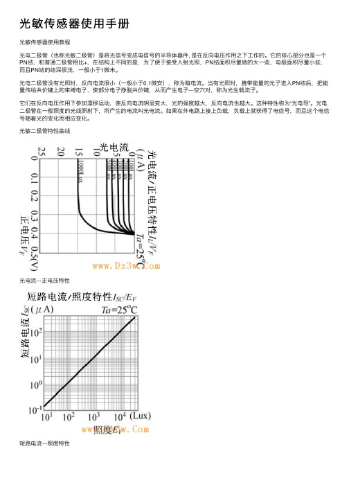
光敏⼆极管特性曲线光电流---正电压特性短路电流---照度特性波长分布特性光敏⼆极管的特点:1、应⽤时反向偏置连接;2、没光照射,呈现极⾼阻值;3、有光照射时,电阻减⼩;4、可作光控关关光敏⼆极管的符号及接线图光敏⼆极管符号光敏⼆极管接线图光电⼆极管与光电三极管的联系与区别光电⼆极管、光电三极管是电⼦电路中⼴泛采⽤的光敏器件。
光电⼆极管和普通⼆极管⼀样具有⼀个PN结,不同之处是在光电⼆极管的外壳上有⼀个透明的窗⼝以接收光线照射,实现光电转换,在电路图中⽂字符号⼀般为VD。
光电三极管除具有光电转换的功能外,还具有放⼤功能,在电路图中⽂字符号⼀般为VT。
光电三极管因输⼊信号为光信号,所以通常只有集电极和发射极两个引脚线。
同光电⼆极管⼀样,光电三极管外壳也有⼀个透明窗⼝,以接收光线照射。
为了使⽤的便利,经常把远红外接收器做成⼀个光敏传感器模块,光敏传感器模块及其电路原理图如下所⽰:光敏传感器模块⼯作电压为+5V,具有数字量电平信号和模拟量电平信号输出,在使⽤过程中,可以根据需要,选择数字量电平信号或模拟量电平信号。
光敏传感器技术数据表说明书
Fig.3 Relative Collector Current vs. Ambient Temperature
Fig.4 Collector Current vs. Irradiance
160
140
2
120
10 C
1
100
80
0.1
60
40
0.01
20
0
0.001
0 10 20 30 40 50 60 70
Collector Dark Current
ICEO
VCE=20V Ee=0mW/cm2
Min Typ Max Unit 400 --- 1100 nm --- 940 --- nm 30 --- --- V
5 --- --- V
--- --- 0.4 V --- --- 100 nA
On State Collector Current
Repair should not be done after the LEDs have been soldered. When repairing is unavoidable, a double-head soldering iron should be used (as below figure). It should be confirmed beforehand whether the characteristics of the LEDs will or will not be damaged by repairing.
λP BVCEO
---
IC=100μA Ee=0mW/cm2
Emitter-Collector Breakdown Voltage
BVECO
光敏传感器的用法 -回复

光敏传感器的用法-回复光敏传感器是一种能够检测光线强度的电子设备。
它基于光敏材料的光电效应工作原理,能够将光转化为电信号。
光敏传感器在各个领域广泛应用,例如照相机、光度计、光电测距仪等等。
本文将从光敏传感器的原理、结构和工作方式,以及其在不同领域的用途等方面进行详细介绍。
一、光敏传感器的工作原理光敏传感器的工作原理基于光电效应,即光照射到光敏材料时会产生电信号。
光敏材料通常是一种半导体材料,例如硅、碲化镉(CdTe)、硒化铟(InSe)等等。
这些材料的能带结构使得它们可以吸收入射光的能量,从而产生光电导致电子的迁移和电流的流动。
当光照射到光敏材料时,光能量激发了光敏材料中的电子,使其从价带跃迁至导带。
跃迁后的电子在导带中运动,从而形成电流。
光敏传感器会测量这个电流的强度,进而获得光线的强度。
二、光敏传感器的结构和工作方式光敏传感器通常由光敏元件和电子电路组成。
光敏元件是光敏材料制成的一小块晶体或薄膜,用于感受光线。
电子电路则是将光敏元件产生的电信号进行放大和处理的部分。
光敏传感器有多种不同的结构和类型。
最常见的类型是光敏二极管和光敏电阻。
光敏二极管由光敏材料制成的二极管,光照射到二极管时,电流的变化将被测量。
光敏电阻则是一种电阻器,光照射到电阻上会改变其电阻值,进而导致电流的变化。
光敏传感器的工作方式可以分为两种:间接检测和直接检测。
间接检测是通过测量光源照射在被测物体上的光强度变化来推断光源的亮度。
而直接检测则是直接测量光源的亮度。
三、光敏传感器的应用领域1. 照相机:光敏传感器是数码相机的核心组件之一。
它用于将光线转化为图像信号,通过后续的图像处理技术生成成像。
2. 光度计:光敏传感器可以测量光的强度,从而实现对环境光照的测量。
这在照明工程、智能家居和室内环境监测等领域非常重要。
3. 光电测距仪:光敏传感器可以用于测量物体与传感器之间的距离。
这在机器人导航、自动驾驶和物体识别等应用中起着关键作用。
TL46对比光敏传感器产品说明书

148CATALOG | Photoelectric Sensors(**)TLCATALOG S E C T I O NTL46Contrast sensor9 ±3 mm18 mm (Lens No.18 glass)22 mm (Lens No.22 glass)28 mm (Lens No.28 glass)40 mm (Lens No.40 glass)Switching frequency10 kHz (mod. TL46-WE color mode)15 kHz (mod. TL46-W)20 kHz (mod. TL46-A/WL)25 kHz (mod. TL46-W...PZ)30 kHZ (mod. TL46-WLF/WE contrast mode)50 kHZ (mod. TL46-WJ)70 kHz (mod. TL46-WH...PZ)Jitter50 μs (mod. TL46-WE color mode)33 μs (mod. TL46-W)25 μs (mod. TL46-A/WL)<20 μs (mod. TL46-W...PZ)16 μs (mod. TL46-WLF/WE contrast mode)<7 μs (mod. TL46-WJ <3 μs (mod. TL46-WH...PZ)Light emission RGB LED white LED Red LED Setting push buttonsTrimmer (precise incremental encoder) mod. TL46-APower supplyVDC 10…30 VVAC VAC/DC OutputPNP •NPN•NPN/PNP •relayAnalogue out 0…5 V Analogue Output (TL46-A/W/WL only)IO-Link V1.1.2 Smart sensor profile double channel I/O(mod. TL46-WH...PZ, TL46-W...PZ)Connectioncable connector •pig-tailApproximate dimensions (mm)31 x 81 x 58Housing material Aluminium Mechanical protectionIP67(**) ATEX II 3DGAPPLICATIONS• Packaging and labeling machinery• Beverage/Food/Cosmetic/Pharmaceutical industries • Printing machinery• Flexographic printing machinery• Very high precision for cutting and sealing applicationsULTRA HIGH SPEED HIGH PERFORMING CONTRAST SENSOR FOR COLOREDREGISTRATION MARK DETECTIONTL46• Ultra Fast model up to 70 kHz and very low 3us jitter (TL46-WH...OZ)• Color mode enhanced model (TL46-WE)• Position mouniting monitoring through IO-Link communication • Mechanical vibration monitoring through IO-Link communication • Wide-spectrum RGB or white LED emission• 7 different models: basic, standard, enhanced, low jitter, color mode, basic IO-Link, ultra fast with IO-Link • Automatic, manual and dynamic settings• 10, 15, 20, 30, 50, 70 kHz switching frequencies• Very low 3us jitter for fast and very precise detection (TL46-WH...OZ)• NPN/PNP/PP and analog outputs• IO-Link connectivity V1.1.2 with smart functions•Standard mounting, M12 connector rotatable to 5 positionsCONTRAST SENSORSPower supply 10 … 30 VDC (limit values) Ripple 2 VPP max.Consumption (output current excluded)40 mA max. at 24 VDC (mod. TL46-A)50 mA max. at 24 VDC (mod. TL46-W/WJ)85 mA max. at 24 VDC 24 VDC with bargraph ON in threshold adjustment mode, 55 mA max at 24 VDC with bargraph OFF in normal functioning mode (mod. TL46-WL)35 mA max. at 24 VDC (mod. TL46-WLF/WE)30mA (mod. TL46-WH...PZ, TL46-W...PZ)Light emission white LED 400-700 nm (mod. TL46-A-4xx); red LED 630 nm (mod. TL46-A-6xx)blue LED 465nm/green LED 520 nm/red LED 630 nm (mod. TL46-W/WL/WLF/WE/WJ/WH...PZ/W...PZ)Detection Distance9 ±3 mm18 mm (Lens No.18 glass) 22 mm (Lens No.22 glass) 28 mm (Lens No.28 glass) 40 mm (Lens No.40 glass)Minimum spot dimension 1.5 x 5 mm; 0.8 x 4 mm (TL46-WJ, TL46-WH...PZ, TL46-W...PZ) Depth of field± 3 mmResponse time 100 μs (mod. TL46-WE, TL46-WH...PZ color mode33 μs (mod. TL46-W)25 μs (mod. TL46-A/WL)20 μs (mod. TL46-W...PZ)16 μs (mod. TL46-WLF/WE contrast mode)10 μs (mod. TL46-WJ)6 μs (mod. TL46-WH...PZ)Switching frequency 10 kHz (mod. TL46-WE, TL46WH...PZ color mode)15 kHz (mod. TL46-W)20 kHz (mod. TL46-A/WL)30 kHz (mod. TL46-WLF/WE contrast mode)50 kHz (mod. TL46-WJ)70 kHz (mod. TL46-WH...PZ)Jitter 50 μs (mod. TL46-WE, TL46-WH...OZ color mode)33 μs (mod. TL46-W)25 μs (mod. TL46-A/WL)20 μs (mod. TL46-W...PZ)16 μs (mod. TL46-WLF/WE contrast mode)<7 μs (mod. TL46-WJ)3 μs (mod. TL46-WH...PZ)Setting SET push-buttons (mod. TL46-W/WL/WLF/WH...PZ/W...PZ)sensivity trimmer (mod. TL46-A)Operating mode DARK/LIGHT selection by switch (mod. TL46-A); automatic DARK/LIGHT selection (mod. TL46-W/WL/WJ) automatic DARK/LIGHT selection in the target/background detection, selectable via wire in the dynamic detection(mod. TL46-WLF/WE/WH)Indicatorsyellow OUTPUT LEDgreen READY LED, orange DELAY LED and KEYLOCK (mod TL46-W/WJ/W...PZ) green READY LED, 4-digit display/DELAY LED/KEYLOCK LED mod. TL46-WLF/WE/WH...PZ orange ARROWS (mod. TL46-A), DELAY LED and KEYLOCK LED 5-segment bargraph (mod. TL46-WL)Dark/light selection Switch; Automatic;Automatic/manual; remote/dynamicDelay0…20ms selectable via delay input0…100ms programmedAuxiliary function Keylock (not available on TL46-WE)Fine Hysteresis regulation (TL46-WL/WLF/WE)Output PNP (mod. TL46-WJ); PNP or NPN; PNP/NPN (mod. TL46-W/WL/WLF/WE by part number);PP/PNP/NPN (TL46-W/WH...PZ); analog output (mod. TL46-A/W/WL)Output current100mASaturaton Voltage= <2VAnalogue Out0,5…5,5V ±10%; 2V on white target 90%; 1…3V ±10%(white 90%) ; 5,5V max Analogue out impedance 2,2 kΩ (short circuit protection)Connection M12 5-pole connectorDielectric strength500 Vac, 1 min between electronics and housingInsulating resistance>20 MΩ, 500 Vdc between electronics and housingElectrical protection class 2, double insulationProtection device Reverse polarity protection, overload and short circuit protection Mechanical protection IP67Ambient light rejection according to EN 60947-5-2Vibrations0,5 mm amplitude, 10 … 55 Hz frequency, for every axis (EN60068-2-6)Shock resistance11 ms (30 G) 6 shock for every axis (EN60068-2-27)Housing material aluminiumLens material PMMA (mod. TL46-A, TL46-W), glass (mod. TL46-W-815G/WL/WLF/WJ/WE) Operating temperature-10 … 55 °CStorage temperature-20 … 70 °CWeight170 g max. TECHNICAL DATA149CATALOG | Photoelectric Sensors150CATALOG | Photoelectric Sensors15,614,41811,530,614,8TL46-A TL46-WL TL46-WLF/WE/WH...PZTL46-W/WJ/W...PZ DIMENSIONS151CATALOG | Photoelectric SensorsAIBLAC DEF G F BABC DHF G FAN B MOyellow OUTPUT LED green READY LED orange DELAY LED orange KEYLOCK LED Bargraph+/- push-buttonsSET push-button Display MARK push-buttonBKGD push-button Light/Dark Switch Orange Indicators Arrows Sensitivity Adjustment KnobTL46-ATL46-WLF/WE/WJTL46-W...PZ/WH...PZTL46-W/WLINDICATORS AND SETTINGSCONNECTIONSStandard 9 mm lensmmAccessory 18 mm lens mmAccessory 28 mm lensmmAccessory 40 mm lensmmHORIZONTAL SPOTVERTICAL SPOTHorizontal spot ispresent in the TL46models with final ‘-L’suffixACCESSORIESDATALOGIC PRODUCT OFFERINGMobile Computers VisionSensors Hand HeldSafety LaserSafety LightLaser Marking。
森霸光電 光敏传感器LS06-S 说明书
光敏傳感器型號:LS06-S森霸光電有限公司典型應用·替代光敏電阻 (CdS)·調節背景光,如LCD 顯示器,電視,PDA ,照相機和 移動電話等·控制照明設備和玩具特性·隨光照度變化在[0,200LUX]綫性輸出 ·其光譜響應特性为红外线 ·具有一定的溫度穩定性 ·低暗電流,低工作照度·符合RoHS 指令 / 無鉛 / 無鎘引腳功能説明引腳名描述1 集电极 2发射极1. 最大额定值(Ta = 25°C)※1 At the position of 2mm from the bottom of the package within 5 seconds. LS06-S產品説明書替代CdS 光敏電阻符合RoHS 環保指令 / 無鉛 / 無鎘 普通型光敏傳感器特性参数符号 额定值 单位集电极-发射级电压 V CEO 70 伏 发射级-集电级电压 V ECO 7 伏 集电极电流 I C 20 毫安 集电极功耗 P D 100 毫瓦 工作温度 T opr -25~+70 度 储存温度T stg -25~+80 度焊接温度(5秒)※1T sol 260 度2. 光电特性(Ta = 25°C)参数 符号 测试条件 最小 典型 最大 单位集电极光电流 I C V CE =5V, E v= 100Lux,(E e=1Mw/cm 2) ※2228 239.5 249 微安集电极暗电流I CEO V CE =5V, E e= 0※210纳安集电极-发射级饱和压降 V CE(sat)I C =2mA,I B =100uA 0.2伏 峰值波长 λp 850 纳米 光谱灵敏度 ∆λ 450~1050 纳米半角度∆θ±55 度 反应时间(上升) t r 15 微秒反应时间(下降)T fV CC =5V, I C =1mAR L =1K 15微秒增益 h FE V CE =5v I C =2mA 6301070 ※2 E v ,E e are illuminance irradiant by CIE standard light source A(tungsten lamp)at 2856K 。