hypermesh运用实例教学文案
Hypermesh学习教程

1.1 实例:创建、编辑实体并划分3D网格本实例描述使用HyperMesh分割实体,并利用Solid Map功能创建六面体网格的过程。
模型如图5-1所示。
图5-1 模型结构本实例包括以下内容。
●导入模型。
●通过面生成实体。
●分割实体成若干个简单、可映射的部分。
●使用Solid Map功能创建六面体网格。
打开模型文件。
(1)启动HyperMesh。
(2)在User Profiles对话框中选择Default(HyperMesh)并单击OK按钮。
(3)单击工具栏()按钮,在弹出的Open file… 对话框中选择solid_geom.hm 文件。
(4)单击Open按钮,solid_geom.hm文件将被载入到当前HyperMesh进程中,取代进程中已有数据。
使用闭合曲面(bounding surfaces)功能创建实体。
(1)在主面板中选择Geom页,进入solids面板。
(2)单击()按钮,进入bounding surfs子面板。
(3)勾选auto select solid surfaces复选框。
(4)选择图形区任意一个曲面。
此时模型所有面均被选中。
(5)单击Create按钮创建实体。
状态栏提示已经创建一个实体。
注意:实体与闭合曲面的区别是实体边线线型比曲面边线粗。
(6)单击return按钮返回主面板。
使用边界线(bounding lines)分割实体。
(1)进入solid edit面板。
(2)选择trim with lines子面板。
(3)在with bounding lines栏下激活solids选择器。
单击模型任意位置,此时整个模型被选中。
(4)激活lines选择器,在图形区选择如图5-2所示线。
(5)单击trim按钮产生一个分割面,模型被分割成两个部分,如图5-3所示。
图5-2 选择边线图5-3 分割实体使用切割线(cut line)分割实体。
(1)在with cut line栏下激活solids选择器,选择STEP 3创建的较小的四面体,如图5-4所示。
hypermesh简易实用教程.
F 合适窗口大小 D display窗口H help文件F2 delete panelF12 auto mesh panel F10 elem check panel F5 mask panel F6 element edit panel Ctrl+鼠标左键旋转Ctrl+鼠标滑轮滑动缩放Ctrl+鼠标滑轮画线缩放画线部分Ctrl+鼠标右键平移F11 quick edit panel Ctrl+F2 取图片保存到F9 line edit panel R rotation 窗口F4 distance panel 可以寻找圆心W windows窗口G Global panel O Option panelShfit+F1……新窗口Shfit+F11 operation窗口Shfit+ctrl 可以透视观察Shfit+F12 smooth 对网格平顺化Shifit+F3 检查自由边,合并结点鼠标中键确认按纽Shot cut一 hypermesh网格划分⑴单元体的划分1.1 梁单元该怎么划分?Replace可以进行单元结点合并,对于一些无法抽取中面的几何体,可以采用surface offset 得到近似的中面线条抽中线:Geom中的lines下选择offset,依次点lines点要选线段,依次选中两条线,然后Creat.建立梁单元:1进入hypermesh-1D-HyperBeam,选择standard seaction。
在standard section library 下选HYPER BEAM在standard section type下选择solid circle(或者选择其它你需要的梁截面。
然后create。
在弹出的界面上,选择你要修改的参数,然后关掉并保存。
然后return.2 新建property,然后create(或者选择要更新的prop),名称为beam,在card image 中选择PBAR,然后选择material,然后create.再return.3 将你需要划分的component设为Make Current,在1D-line mesh,选择要mesh的lines,选择element size,选择为segment is whole line,在element config:中选择bar2,property选择beam(上步所建的property.然后选择mesh。
hypermesh基础培训教程(多场合)
hypermesh基础培训教程(多场合)Hypermesh基础培训教程一、引言Hypermesh是一款功能强大的有限元前处理器,广泛应用于结构分析、热分析、流体分析等领域。
本教程旨在帮助初学者快速掌握Hypermesh的基础操作,为后续的高级应用打下坚实基础。
通过本教程的学习,读者将能够熟练地进行几何建模、网格划分、材料属性定义、边界条件施加等基本操作。
二、Hypermesh界面及基本操作1.启动Hypermesh在安装完Hypermesh软件后,双击桌面图标启动程序。
初次启动时,系统会提示设置工作目录,选择一个便于管理的路径即可。
2.界面介绍Hypermesh界面主要包括菜单栏、工具栏、主窗口、状态栏等部分。
菜单栏包含文件、编辑、视图、网格、工具等菜单,通过菜单可以执行各种操作。
工具栏提供了常用的快捷操作按钮,方便用户快速执行命令。
主窗口用于显示几何模型、网格、分析结果等。
状态栏位于界面底部,显示当前操作的状态信息。
3.基本操作(1)打开模型:通过菜单栏“文件”→“打开”命令,选择相应的几何文件(如iges、stp等格式),打开模型。
(2)缩放、旋转、平移视图:通过工具栏的相应按钮,可以调整视图的显示。
同时,鼠标滚轮可以控制视图的缩放。
(3)选择元素:鼠标左键单击选择单个元素,按住Ctrl键同时单击可以选择多个元素。
(4)创建集合:通过菜单栏“编辑”→“创建集合”命令,可以将选中的元素创建为一个集合,便于后续操作。
(5)撤销与重做:通过菜单栏“编辑”→“撤销”或“重做”命令,可以撤销或重做上一步操作。
三、几何建模1.几何清理在实际工程中,导入的几何模型往往存在冗余面、重叠边等问题,需要进行几何清理。
Hypermesh提供了丰富的几何清理工具,如合并顶点、删除线、删除面等。
2.创建几何元素Hypermesh支持创建点、线、面、体等几何元素。
通过菜单栏“几何”→“创建”命令,选择相应的几何元素创建工具,如创建点、创建线、创建面等。
hypermesh运用实例(1)

运用HyperMesh软件对拉杆进行有限元分析问题的描述拉杆结构如图1-1所示,其中各个参数为:D1=5mm、D2=15mm,长度L0=50mm、L1=60mm、L2=110mm,圆角半径R=mm,拉力P=4500N。
求载荷下的应力和变形。
图1-1 拉杆结构图有限元分析单元单元采用三维实体单元。
边界条件为在拉杆的纵向对称中心平面上施加轴向对称约束。
模型创建过程CAD模型的创建拉杆的CAD模型使用ProE软件进行创建,如图1-2所示,将其输出为IGES格式文件即可。
图1-2 拉杆三维模型CAE模型的创建CAE模型的创建工程为:将三维CAD创建的模型保存为文件。
(1)启动HyperWorks中的hypermesh:选择optistuct模版,进入hypermesh 程序窗口。
主界面如图1-3所示。
(2)程序运行后,在下拉菜单“File”的下拉菜单中选择“Import”,在标签区选择导入类型为“Import Goemetry”,同时在标签区点击“select files”对应的图形按钮,选择“”文件,点击“import”按钮,将几何模型导入进来,导入及导入后的界面如图1-4所示。
图1-3 hypermesh程序主页面图1-4 导入的几何模型(4)几何模型的编辑。
根据模型的特点,在划分网格时可取1/8,然后进行镜像操作,画出全部网格。
因此,首先对其进行几何切分。
1)曲面形体实体化。
点击页面菜单“Geom”,在对应面板处点击“Solid”按钮,选择“surfs”,点击“all”则所有表面被选择,点击“creat”,然后点击“return”,如图1-5~图1-7所示。
图1-5 Geom页面菜单及其对应的面板图1-6 solids按钮命令对应的弹出子面板图1-7 实体化操作界面2)临时节点的创建。
点击页面菜单“Geom”,在对应面板中点击“nodes”按钮,在弹出的子面板中选择“on line”,选择如图1-8所示的五根线,点击“creat”,然后return,这样就创建了临时节点。
hypermesh-hyperview应用技巧与高级实例
hypermesh-hyperview应用技巧与高级实例目录1. 引言1.1 背景和意义1.2 结构概述1.3 目的2. HyperMesh基础应用技巧2.1 网格建模2.2 材料定义和属性设置2.3 边界条件设置3. HyperView结果后处理技巧3.1 数据导入与预处理3.2 结果展示与分析3.3 动画与报告生成4. HyperMesh高级实例讲解4.1 汇合区域的创建和优化4.2 拓扑优化与形状优化方法比较分析4.3 多物理场耦合仿真案例研究5 结论和总结1. 引言1.1 背景和意义在工程设计与分析领域中,有着众多的设计软件和仿真工具。
其中,Hypermesh与HyperView作为Altair HyperWorks软件套件中的两大核心模块,提供了强大而全面的功能,被广泛应用于结构、材料、流体等领域的建模、优化以及后处理等任务。
Hypermesh作为一款先进的有限元前处理软件,在结构建模方面具备丰富的功能和强大的求解能力。
通过其快速且高效的网格划分算法,用户可以轻松地将复杂几何图形转换成可用于数值计算的网格模型。
此外,在材料定义和属性设置、边界条件设置等方面,Hypermesh提供了灵活性强、易于操作的工具,使得用户能够更加精确地描述系统,并满足各种特定需求。
与此同时,HyperView则是一款专业级别的有限元后处理工具。
它不仅支持各类有限元结果数据文件的导入,并能够对结果进行处理、展示和分析,而且还提供了丰富多样的可视化功能。
用户可通过HyperView直观地查看、评估仿真结果,并生成动画和报告,以便更好地理解和传达仿真结果。
本文将重点介绍Hypermesh与HyperView的应用技巧与高级实例,帮助读者更好地掌握这两款工具的使用方法,提高工程设计与分析的效率和准确性。
1.2 结构概述本文共分为5个部分。
首先,在引言部分(第1节)中,我们将介绍本文的背景、意义和结构概述。
其次,第2节将详细讲解Hypermesh的基础应用技巧,包括网格建模、材料定义和属性设置、边界条件设置等方面。
HyperMesh傻瓜教程【范本模板】

强度分析以A380铝支架分析为例:1.Start license services双击, 进入界面,再点击Start Server,取得软件应用许可,进入Hyper mesh工作界面;2.选择模块Nastran双击,弹出对话框,选择Nastran点击OK。
点击斜向下的绿色箭头,进入界面,将已建好的模型导入HyperMesh;3.选择模型,去实体选择要分析的模型,点击图标变灰色,隐藏其它模型。
点击F2,框选模型(如未选中,模型为壳层),将实体(solid)去掉,只留下壳层(1111)。
;4.数模几何清理(auto cleanup 和F11),避免两条轮廓线过于接近或夹角太小(小于30度),再进行人工修清理模型曲线,点击F11,进入界面,一般使用下图1、2、5创建点和点之间的线、点垂直于线的线、删除特征线(鼠标左键去掉曲线,右键添加)去倒角,geom,defeature,surf fillets,find,选中要去掉的倒角面,remove。
5.切法兰面为了确定零件上与加载点相关联的节点位置,我们在约束(螺栓位置)和加载处切法兰面。
(5。
1)找到圆心Geom-circle—find center;常按鼠标左键,在白线上选择三点,点击“find”,出现圆心(5。
2)画圆center&radius 点找到的圆心,输入radius尺寸,点N1,在面上点三个点,点“create"按住左键选中曲线找到节点, M6的螺栓,法兰半径6.5;M8/8。
5,M10/10。
5,M12/12.5;(5。
3)Surface edit -trim with lines—with lines;选面、点鼠标中键,选线, 点鼠标中键,选择N1、N2、N3点。
6.生成表面三角形壳单元在component中建shell,右键make current,使生成的壳单元在该层中,若生成的网格没有在shell中,可以通过tool-organize-elems—retrieve来转移点击F12—surface/trias(选择三角形单元)选中-mesh,接下来再修理网格(左键增加节点,右键去掉节点),例如,倒角、加强筋位置至少两层单元,应力集中、加载处细分网格;7.检查壳单元,并局部优化.(7.1) 检查网格质量,点击F10/2—d,在界面内点击min。
hypermesh实例教学

2. 抽取中性面(钣金件的分析)
• 对于钣金件,为减小计算工作量,常将3D 分析转为2D分析。
3.几何局部简化处理(曲面)
• 为提高网格质量,减少计算时间。常将一些对 零部件功能性影响不大的小孔、边与边之间的 小倒角,面与面之间的小倒角去掉。 • F12: automesh,网格编辑 • F10:网格质量检查 • Defeature模糊处理。如下: • Pinholes(小孔),找到小于diameter < field的孔, 并删除。 • surf fillets(面倒角), edge fillets(边倒角), 找到小于min radius <field的倒角,并删除。
Hyperworks实例
1. 几何清理(实体)
• Non-manifold :两个以上的面共用一条边。黄色。处理 措施为删除其中多余的面。 • Keep tangency :使由封闭曲线构成的面与封闭曲线相 切。 • Auto create (free edges):选择封闭曲线的1条边后,其
它边自动选择。 • F2:删除命令。快捷键。
4.提高曲面的拓扑结构
减少短边,使各个分块更加均匀。 • 通过移除硬点, point edit_replace point edit_replace • 移除内部无用的硬点interior fixed points , point edit_suppress • 重新划分曲面。F11 • F4。测量节点(NODE)或硬点(POINT)之间的距离。 • 使用Surface Edges > (Un)Suppress 或toggle去掉能引起小 网格的小边。 • SHITT+F2.删除多余的node. • 注意:对称体。如园、圆柱体,要从中心或中心面对称 剖开。
(完整word版)hypermesh教程
第一章 HyperMesh入门首先我们要了解什么是mesh,简单的说mesh就是网格的划分。
有过有限元分析背景的人都知道,做有限元分析首先第一步工作就是建模,就是把分析对象按照一定的尺寸、比例划分成相互连接、不间断的网格单元,成为一个可以计算的力学模型,这是进行有限元计算的基础。
其划分的结果对于以后计算的结果将产成直接的影响,或者说mesh 是保证有限元分析结果准确的重要条件。
下面我就最简单的分析对象-—金属壳体,向大家讲述怎样进行一个物体的mesh。
我们所用软件是HyperMesh,它对于有限元的前处理和后处理都具有比较强大功能。
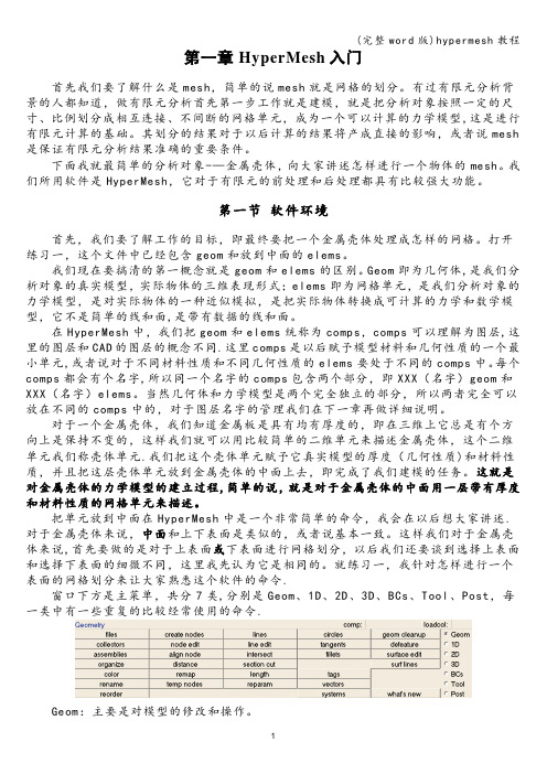
第一节软件环境首先,我们要了解工作的目标,即最终要把一个金属壳体处理成怎样的网格。
打开练习一,这个文件中已经包含geom和放到中面的elems。
我们现在要搞清的第一概念就是geom和elems的区别。
Geom即为几何体,是我们分析对象的真实模型,实际物体的三维表现形式;elems即为网格单元,是我们分析对象的力学模型,是对实际物体的一种近似模拟,是把实际物体转换成可计算的力学和数学模型,它不是简单的线和面,是带有数据的线和面。
在HyperMesh中,我们把geom和elems统称为comps,comps可以理解为图层,这里的图层和CAD的图层的概念不同.这里comps是以后赋予模型材料和几何性质的一个最小单元,或者说对于不同材料性质和不同几何性质的elems要处于不同的comps中。
每个comps都会有个名字,所以同一个名字的comps包含两个部分,即XXX(名字)geom和XXX(名字)elems。
当然几何体和力学模型是两个完全独立的部分,所以两者完全可以放在不同的comps中的,对于图层名字的管理我们在下一章再做详细说明。
对于一个金属壳体,我们知道金属板是具有均有厚度的,即在三维上它总是有个方向上是保持不变的,这样我们就可以用比较简单的二维单元来描述金属壳体,这个二维单元我们称壳体单元.我们把这个壳体单元赋予它真实模型的厚度(几何性质)和材料性质,并且把这层壳体单元放到金属壳体的中面上去,即完成了我们建模的任务。
hypermesh教程4
hypermesh教程437710.1 在HyperMesh 环境中建⽴⼀个ABAQUS 分析本实例主要进⾏如下讲解。
●加载ABAQUS 界⾯和模型。
●定义材料和properties ,并赋予component 。
●查看实体单元卡⽚*SOLID SECTION 。
●定义弹簧单元卡⽚*SPRING ,并建⽴相应的component 。
●创建弹簧单元类型为*SPRING1的单元。
●将property 赋予指定的单元。
加载ABAQUS 界⾯和模型。
在HyperMesh 安装程序中,包含了⼀组标准的⽤户界⾯,它们包含RADIOSS (Bulk Data Format )、RADIOSS (Block Format )、ABAQUS 、Actran 、ANSYS 、LS-DYNA 、MADYMO 、Nastran 、PAM-CRASH 、PERMAS 以及CFD 等界⾯。
当ABAQUS ⽤户界⾯被加载时,HyperMesh 中相应的有⽤界⾯被加载,⽽没⽤的界⾯被去除,⼀些针对ABAQUS 的特定界⾯也被加载。
(1)打开菜单,选择Preferences >User Profiles 。
(2)选择ABAQUS 。
(3)选择Standard3D 模块。
(4)打开菜单,选择File > Open > Model 。
(5)找到⽂件ABAQUS3_0tutorial.hm 。
(6)单击Open 按钮。
定义材料。
HyperMesh 对多种ABAQUS 材料类型提供了⽀持。
在这个实例中,将在HyperMesh 中建⽴⼀个ABAQUS 的弹性材料模型,然后这个材料将被关联到property ,property 将被关联到component ,如图10-1创建材料所⽰。
(1)右键单击Model Browser ,选择Create > Material 。
(2)在Name 中输⼊STEEL 。
(3)在Card Image 中选择ABAQUS_MA TERIAL 。
CAEHyperMesh解析PPT教学课件
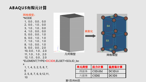
网格模型: *NODE
1, 0.0 , 0.0 , 0.0
12
S2 9
11
10
2, 0.0 , 1.0 , 0.0
S4
3, 1.0 , 1.0 , 0.0
4, 1.0 , 0.0 , 0.0 5, 0.0 , 0.0 , 1.0 6, 0.0 , 1.0 , 1.0 7, 1.0 , 1.0 , 1.0
前面的逗号,在温度文件中第一行末尾粘贴 4. Replace P with F 5. 另存为Liner_gas_HTC.inp
第29页/共60页
垫片单元
单元类型: 三棱柱:GKC3D6N 六面体:GKC3D8N
网格划分: 1. 在建立缸垫几何模型时,对压波、油孔、水孔密封区域建立边缘线; 2. 在HM中用边缘线进行切割上述区域; 3. 在缸垫的一个平面上分别对压波、油孔、水孔、本体划分面网格,并存放在
srf_liner_block_x_0
srf_liner_block_x_1
srf_liner_gasket_x
srf_headbolt_sec_x_0 x(1~):表示沿曲轴方向坐标系的 正方向开始命名 0~1:表示与曲轴垂直方向坐标系的 正方向开始命名 其他部件按照上述命名方法进行命 名,以要建立接触面的那个部件的 英文名称作为命名的开头然后加“_” 然后是与之相接触的部件名称。
第26页/共60页
HyperMesh-施加函数变载荷
火力板:
1.178e-3*(-1.9401*(sqrt(x*x+y*y)/50)^3+ 1.1356*(sqrt(x*x+y*y)/50)^2+ 0.6834*(sqrt(x*x+y*y)/50) + 0.602)
hypermesh技巧培训讲学
1、我想提取一个面的线,映射到另外的面上,然后用那个线来分面,该怎么做呢?如果是几何面,但是没有你需要的边界线的话,你可以在几何面上已有的边界线上create nodes,然后利用这些nodes --〉lines /create,建立你需要的线,再project;或者最简单的办法,选择surf edit/line from surf edge如果是网格面,你可以geom/fea->surface,再project,或者直接project nodes,利用nodes 可以直接划分面2、hypermesh中如何将网格节点移动到指定的线或者面上。
project.3、面上网格分不同的comp划分,但划分后所有网格并不是连续的,只有同一个comp 的网格连续,和临近的comp相邻的网格不连续,就是存在重叠的单元边和结点,如何合并为连续的单元1、Tool ->edges 下找出并合并面单元的自由边和找出并删除重节点2、Tool ->faces 下找出并合并体单元的自由面和找出并删除重节点4、我的模型画出六面体单元了,但是是8节点的,想变成20节点的,怎么变?我用的是solidmap功能生成六面体单元的?1D or 2D or 3D下面的order change5、直接在已分网的体表面上,create elements through nodes,这个要在哪个菜单实现?我找不着edit/element中不是有个create吗?那就是通过node建单元6、对灰线构成的区域划分2D网格,网格后发现灰线变成了红线,是怎么回事呢?对计算结果有影响么?灰色的是lines,至于为什么画完网格后会变成红色,是因为生成了surface,surface 的自由边会由红色来表示。
请注意为什么会生成surface,是因为你选择了mesh/keep surface 这个选项7、偶很想知道OI mesh定义是什么,和普通的mesh有什么区别普通mesh的网格经过clean up 或QI 调整后就跟QI mesh划分的网格效果差不多,QI 的具体参数可以自行设定。
hypermesh入门篇
hypermesh入门篇(转)2009-09-08 08:19其实各种CAE前处理的一个共同之处就是通过拆分把一个复杂体拆成简单体。
这个思路一定要记住,不要上来就想在原结构上分网,初学者往往是这个问题。
刚开始学,day1,day2,advanced training 和HELP先做一遍吧。
另外用熟24个快捷键。
做一下HELP里面的教程,多了解一些基本的概念和操作。
这样会快点入门。
论坛更多的是方法。
划分的方法要灵活使用,再有就是耐心。
1、如何将.igs文件或.stl文件导入hypermesh进行分网?files\import\切换选项至iges格式,然后点击import...按钮去寻找你的iges文件吧。
划分网格前别忘了清理几何2、导入的为一整体,如何分成不同的comps?两物体相交,交线如何做?怎样从面的轮廓产生线(line)?都用surface editSurface edit的详细用法见HELP,点索引,输入surface edit3、老大,有没有划分3D实体的详细例子?打开hm,屏幕右下角help,帮助目录下hyperworks/tutorials/hyermesh tutorials/3D element,有4个例子。
4、如何在hypermesh里建实体?hm的几何建模能力不太强,而且其中没有体的概念,但它的曲面功能很强的.在2d面板中可以通过许多方式构建面或者曲面,在3D面板中也可以建造标准的3D曲面,但是对于曲面间的操作,由于没有"体"的概念,布尔运算就少了,分割面作就可以了5、请问怎么在hypermesh中将两个相交平面到圆角啊?defeature/surf fillets6、使用reflect命令的话,得到了映射的另一半,原先的却不见了,怎么办呢?法1、在选择reflect后选择duplicate复制一个就可以法2、先把已建单元organize〉copy到一个辅助collector中,再对它进行reflect,将得到的新单元organize〉move到原collector中,最后将两部分equivalence,就ok拉。
hypermesh基础教程(进门、经典)[宝典]
![hypermesh基础教程(进门、经典)[宝典]](https://img.taocdn.com/s3/m/6430043225c52cc58bd6beac.png)
hypermesh基础教程(进门、经典)[宝典] 第一章 HyperMesh入门首先我们要了解什么是mesh,简单的说mesh就是网格的划分。
有过有限元分析背景的人都知道,做有限元分析首先第一步工作就是建模,就是把分析对象按照一定的尺寸、比例划分成相互连接、不间断的网格单元,成为一个可以计算的力学模型,这是进行有限元计算的基础。
其划分的结果对于以后计算的结果将产成直接的影响,或者说mesh是保证有限元分析结果准确的重要条件。
下面我就最简单的分析对象——金属壳体,向大家讲述怎样进行一个物体的mesh。
我们所用软件是HyperMesh,它对于有限元的前处理和后处理都具有比较强大功能。
第一节软件环境首先,我们要了解工作的目标,即最终要把一个金属壳体处理成怎样的网格。
打开练习一,这个文件中已经包含geom和放到中面的elems。
我们现在要搞清的第一概念就是geom和elems的区别。
Geom即为几何体,是我们分析对象的真实模型,实际物体的三维表现形式;elems即为网格单元,是我们分析对象的力学模型,是对实际物体的一种近似模拟,是把实际物体转换成可计算的力学和数学模型,它不是简单的线和面,是带有数据的线和面。
在HyperMesh中,我们把geom和elems统称为comps,comps可以理解为图层,这里的图层和CAD的图层的概念不同。
这里comps是以后赋予模型材料和几何性质的一个最小单元,或者说对于不同材料性质和不同几何性质的elems要处于不同的comps中。
每个comps都会有个名字,所以同一个名字的comps包含两个部分,即XXX(名字)geom和XXX(名字)elems。
当然几何体和力学模型是两个完全独立的部分,所以两者完全可以放在不同的comps中的,对于图层名字的管理我们在下一章再做详细说明。
对于一个金属壳体,我们知道金属板是具有均有厚度的,即在三维上它总是有个方向上是保持不变的,这样我们就可以用比较简单的二维单元来描述金属壳体,这个二维单元我们称壳体单元。
HyperMesh入门实例

8.保存文件如图14,
图表14
9.在BCs面板中OptiStruct运行分析,如图15;
图表15
10.在Post面板中用contour察看结果,如图16;
图16
图表3
3.在Geom面板点create nodes定义一个节点,如图4,
图表4
用circles画一个半径50mm的圆,如图5;
图表5
在2D面板点spline,以圆为边缘作一面,如图6
图表6
4.在collectors中定义一名plate的薄板,如图7;
图表7
编辑厚度为1mm,如图8
图表8
5.在2D面板中点automesh在面上画网格,在屏幕的数字上点左右键可以增加或减少格数,如图9;
HyperMesh入门实例
一个简单的例子,希望对初学者有用。
1.在屏幕右下global中,加载optistruct模版,如图1:
图表1
2.在collectors中定义一名为steel的材料,card image选择MAT1,如图2;
图表2
点creat/edit定义材料特性如图3,然后点return返回。
图表9
6.在BCs面板中选constraints定义圆周上的节点为固定点,如图10,
图表10
7.在collectors中定义名为force的加载,如图11;
图表11
在BCs中选forces定义一大小为10牛的力,如图12;
图表12
在BCs中用load steps定义载荷步force,如图13;loadcols选auto1和force.
Hypermesh10.0实例教程之一

Hypermesh10.0实例教程之一Hypermesh 10.0 实例教程In this tutorial, you will learn how to:Create a circle, arc, line, and tangent lines Duplicate and translate lines Edit lines by splitting and displaying their IDs Delete redundant arcs and lines Duplicate and reflect an arc Create a surface square and two parallel lines on an X-Y plane Create fillet between two linesSometimes CAE users need to create models from sketches where there is no pre-existing geometry. The tools in this tutorial will help you accomplish that task.Exercise: Creating and Editing Line DataThis exercise teaches you how to create lines and surfaces.Step 1: Create a component collector to geometry.1. Access the components sub-panel in one of the following ways:From the toolbar, click components (). From the Menu Bar, select Collectors, then Create and click Components. 2. For comp name = type geometry.3.Use the switch () to toggle from card image = to no card image.4. Click color and chose yellow.5. Click create.6. Click return.Step 2: Create nodes.1. On the standard toolbar, click Isometric View, ().2. Access the create nodes panel in one of the following ways:Create five nodes by entering the X, Y, and Z coordinates from the following table and3. Go to the type in sub-panel.Hypermesh 10.0 实例教程5. Click return.6. Press f to fit the model to the model to the screen.Step 3: Display the node IDs.1. Pick the Tool page and click numbers to access the Numbers panel.2. Change the entity type to nodes.3. Select nodes and on the extended entity selection menu select all.4. Click on to display all the node IDs.5. Click return.Step 4: Create a circle.1. Access thecircles panel in one of the following ways:From the Menu Bar, select Geometry, then Create, then Circles From the main menu, select theGeom page, and select circles2. Go to the center radius sub-panel.3. With the active selector set to node list, pick node 2 from the graphics area. This will be the location of the c ircle’s center.4. Switch () the orientation vector to the X-axis.), pick node 2 from the graphics area. 5. With the active selector set to base point (In this case, the base point defines the position of the plane on which the circle is going to be created.6. Toggle () to circle.7. For radius=, specify 5.8. Click create.9. Remain in the Circles: Center and Radius sub-panel.Step 5: Create an arc.1. Toggle from circle to arc.2. With the active selector set to node list, pick node 2 from the graphics area. This will be the center of the arc.3. Verify that the orientation vector is set to X-axis.4. Pick the node with ID number 2 again as the base for the axis of rotation.5. For angle = specify 180.6. For radius = specify 2.5.7. For offset = specify 90.8. Click create to create an arc.Hypermesh 10.0 实例教程9. Click return to exit the circles panel.10. From the standard toolbar, click Rear ().Step 6: Create a line.1. Access the lines panel in one of the following ways:From the Menu Bar, select Geometry, then Create, then Lines From the main menu, select the Geom page, then select lines2. Go to the from nodes sub-panel.3. Pick the nodes with ID number 4 and node 5 in node list.4. Click create to create a line between nodes 4 and5.5. Click return.Step 7: Duplicate and translate lines.1. Access the translate panel in one of the following ways:From the Menu Bar, select Geometry, then Translate, then Lines From the main menu, select the Tool page, then select translate2. Change the entity type to lines.3. Pick the line that was created between nodes 4 and 5.Select lines, then duplicate, then current comp from the extended menu to copy the new 4. line into the current component (Geometry).5. Click the plane and vector collector switch and select y-axis.6. Click magnitude = and enter 10.0.7. Click translate -.Hypermesh 10.0 实例教程8. Click return.Step 8: Edit lines by splitting at a line.1. Access the line edit panel in one of the following ways:From the Menu Bar, select Geometry, then Edit, then LinesFrom the main menu, select the Geom page, and then select line edit2. Go to the split at line sub-panel.3. With the lines selector active, pick the circle.4. Click cut line and pick the line between node 4 and node5.5. Click split.The circle has one quarter split off from the rest.Repeat this procedure, picking the remaining 3/4 arc of the circle and the other line that6. was just translated.7. Click return.Step 9: Display the line IDs.1. Go to the numbers panel.2. Change the entity type to lines.3. Click lines, then all from entity selection menu.4. Click on to display all the line IDs.5. Click return.Step 10: Delete a redundant arc.1. Access the delete panel in one of the following ways:From the Collectors toolbar, click Delete ()From the main menu, select the Tool page, then select delete2. Change the entity type to lines.3. Select the lower semi-circle (line IDs 5 and 10) from the graphics area.4. Click delete entity to delete the redundant arc.5. Click return.Step 11: Duplicate and reflect an arc.1. Access the reflect panel in one of the following ways:From the Menu Bar, select Geometry, then Reflect, then Lines From the main menu, select the Tool page then select reflect2. Change the entity type to lines.3. Choose the arc (line ID 2) from the graphics area.4. Click the plane and vector collector switch and select z-axis.5. Pick node 2 as the base node.Select lines, then duplicate, then original comp from the extended entity selection menu 6. to copy the new line into the current component (Geometry).7. Click reflect to create the lower arc.8. Click return.Step 12: Create two tangent lines.1. Go to the Lines panel, at tangents sub-panel.2. Select the node with ID number3.3. Click the line selector to make it active.4. Select the semi-circular line with ID number 8.Note: Line ID may be different, depending on whether you needed to perform the split/delete/duplicate tasks more than once.5. Click find tangent.There are two tangent lines on the screen.6. Pick one of the tangents.7. Repeat steps 4-5.8. Select the other tangent.Hypermesh 10.0 实例教程9. Click return to exit the tangent panel.Step 13: Redisplay the line IDs.1. Go to the Numbers panel.2. Change the entity type to lines.3. Click lines, then all from the extended entity selection menu.4. Click on to display all the line IDs.5. Click return to exit the numbers panel.Step 14: Split curves by tangent line and delete redundant line. 1. Go to the Line Edit panel and enter split at line sub-panel.2. Pick semi-circular line 8 for lines and tangent line 12 for cut line.Note: Line ID may be different.3. Click split to split line 8 with line 12.4. Repeat steps 3-5 in order to cut curved line 8 with tangent line 13 in line edit panel.5. Press the F2 key to jump into delete panel from line edit panel.6. Select the curved lines between tangent lines 12 and 13.7. Click delete entity to delete the curves.8. Click return twice to go back to main menu.Hypermesh 10.0 实例教程Step 15: Create a component collector for surfaces.1. Enter the components panel.2. Click name = and enter surfaces.3. Click the switch under creation method and select no card image.4. Click color and select purple.5. Click create.6. Click return to exit the components panel.Step 16: Create a surface square on an X-Y plane.1. Access the Planes panel:From the main menu, select the 2D page, then select planes2. Go to the square sub-panel.3. Set the orientation vector to z-axis.Hypermesh 10.0 实例教程4. For base node, choose the node with ID number 1 to be the base reference node.5. Switch from mesh, keep surf to surface only.6. For size = enter 30.7. Click create to create a square surface.8. Click return to exit the planes panel.Step 17: Create a line that connects two parallel lines on an X-Y plane. 1. Access the Lines panel.2. Go to the at intersection sub-panel.Select z-axis (located at the bottom-center of the panel, shared between the controls for 3. elements with plane and lines with plane) to represent the intersection plane.The reason for choosing the z-axis is that you want to createthe line on the X-Y plane. 4. For base, choose the node with ID number 1 to be the base node.5. Use the lines with plane column.6. For line list, choose the two straight lines that are perpendicular to the X-Y plane.A bold line displayed on the screen represents the result.7. Click intersect to create the line.8. Click return to exit the panel.Step 18: Switch the current working component surfaces to geometry. 1. In the Model browser right-click the geometry component and click Make Current. From this point onwards any element or geometry created will be placed in the geometry component collector.Step 19: Extend a line to a surface edge.1. On the standard views toolbar, click User Views(2. Click Iso1.3. Go to the Line Edit panel.4. Go to the extend line sub-panel.5. Toggle from distance = to to:.6. Change the entity type from node to line.Activate the top line selector and pick the line created in step 17--the line that passes7. through node 1-- as the line to be extended.A red V marks the beginning of the line to be extended.Activate the lower line selector and--with the view still in iso1--select the lower-right edge9. of the purple plane.11. Click extend +.You can see the line is extended to reach one surface edge.12. Click return to exit the Line Edit panel.The result should resemble the following image. ).Hypermesh 10.0 实例教程Step 20: Create a fillet between two lines.1. Access the line panel in one of the following ways:From the Menu Bar, select Geometry, then Create, then Lines. From the main menu, select the Geom page, then select lines.2. Go to the fillets sub-panel.You will use the create option.3. Check trim original lines.4. For radius=, enter5.5. For 1st line, pick the vertical line through which the lineextended in step 19 passes. 6. For 2nd line, pick the extended line from step 19.“Please select fillet quadrant" displays in the status bar. HyperMesh is asking you to select a reference location for the fillet.Hypermesh 10.0 实例教程7. Pick the upper-right X for the fillet quadrant, as shown in the image.HyperMesh immediately creates a fillet on the screen.8. Click return to exit the Linespanel.Hypermesh 10.0 实例教程Step 21: Trim a line by plane and delete a redundant line segment. 1. Go to the Line Edit panel.2. Go to the split at plane sub-panel.3. With the lines selector active, select the vertical line that does not have a fillet.4. Set the orientation vector to z-axis.5. Choose node 1 as the base node.6. Click split to split line 4 by the X-Y plane.7. Press the F2 key to access the delete panel.8. Switch the entity type to lines.Choose the small line segment under the X-Y plane, and click delete entity to remove the9. line segment.10. Click return twice to return to the main menu.Step 22: Remove all temp nodes.1. Access the temp nodes panel in one of the following ways:From the Menu Bar, select Mesh, then Delete, then Nodes From the main menu, select the Geom page, then select temp nodes2. Click clear all to remove all temp nodes.3. Click return to return to the main menu.Step 23: Change the rendering mode.1. On the visualization toolbar, click Shaded Geometry (The plane (purple) becomes shaded instead of wire frame. ).Hypermesh 10.0 实例教程Step 24: Export all geometry as an IGES file.1. On the Files menu point to Export and click IGES Geometry.2. Click Export geometry,3. Click File type: Iges.4. Input a File name.5. Click Export to save your file.The IGES file you have generate can be shared with other CAD packages such as UG, Catia, and ProE. , on the Export tab.。
hypermesh入门篇
hypermesh入门篇(转)2009-09-08 08:19其实各种CAE前处理的一个共同之处就是通过拆分把一个复杂体拆成简单体。
这个思路一定要记住,不要上来就想在原结构上分网,初学者往往是这个问题。
刚开始学,day1,day2,advanced training 和HELP先做一遍吧。
另外用熟24个快捷键。
做一下HELP里面的教程,多了解一些基本的概念和操作。
这样会快点入门。
论坛更多的是方法。
划分的方法要灵活使用,再有就是耐心。
1、如何将.igs文件或.stl文件导入hypermesh进行分网?files\import\切换选项至iges格式,然后点击import...按钮去寻找你的iges文件吧。
划分网格前别忘了清理几何2、导入的为一整体,如何分成不同的comps?两物体相交,交线如何做?怎样从面的轮廓产生线(line)?都用surface editSurface edit的详细用法见HELP,点索引,输入surface edit3、老大,有没有划分3D实体的详细例子?打开hm,屏幕右下角help,帮助目录下hyperworks/tutorials/hyermesh tutorials/3D element,有4个例子。
4、如何在hypermesh里建实体?hm的几何建模能力不太强,而且其中没有体的概念,但它的曲面功能很强的.在2d面板中可以通过许多方式构建面或者曲面,在3D面板中也可以建造标准的3D曲面,但是对于曲面间的操作,由于没有"体"的概念,布尔运算就少了,分割面作就可以了5、请问怎么在hypermesh中将两个相交平面到圆角啊?defeature/surf fillets6、使用reflect命令的话,得到了映射的另一半,原先的却不见了,怎么办呢?法1、在选择reflect后选择duplicate复制一个就可以法2、先把已建单元organize〉copy到一个辅助collector中,再对它进行reflect,将得到的新单元organize〉move到原collector中,最后将两部分equivalence,就ok拉。
HYPERMESH实例分析课件

5、几何清理
A 导入几何模型:通过FILE_IMPORT子面板(IGES:可 导入*.igs)文件
文件地址:
D:/altair/tutorials/hm/raw_iges_data .iges
精
精
点击
改变边显示模式
精
B 模型几何的拓扑显示: 自由边:自由边只属于一个曲面,默认颜色为红色。在 一个经过几何清理的模型中,自由边通常只存在于部件的 外周或者环绕在内部孔洞的周围。 共享边:共享边被两个相邻曲面所共有,默认颜色为绿色。 压缩边:压缩边为两个相邻曲面所共有,但在划分网格时 被忽略被压缩边,不会生成节点,默认颜色为蓝色 T型连接边:表示曲面的边界被三个或三个以上的曲面所 共享,默认颜色为黄色
精
面板菜单:显示每一页面上可用的功能,可通过点击与功 能相应的按钮来实现这些功能
标签域:位于图形区域的左侧,列出一些很有用的工具, 包含多个特征页面,如UTILITY菜单,MODEL浏览器, 和SOLVER浏览器等
命令窗口:可将HYPERMESH的命令直接键入文本框执行 的方式代替使用图形用户界面功能执行命令
精
导入文件(HM/CAD/FEM) 设置模
版
几何清理
建立材料卡片
建立几何,单元集
划分单元
单元检查与优化 建立载荷集 施加
载荷 建立载荷工况 设置计算参数
输出有限元文件 求解器求解 进行
后处理
精
3、HYPERMESH8.0窗口界面
主要包括以下几个窗口界面: 下拉菜单 图形区 工具栏 标题栏 页面菜单 面板菜单 标签域 命令窗口
有限元分析分为三大步:有限元前处理,有限元求解,有 限元后处理。
- 1、下载文档前请自行甄别文档内容的完整性,平台不提供额外的编辑、内容补充、找答案等附加服务。
- 2、"仅部分预览"的文档,不可在线预览部分如存在完整性等问题,可反馈申请退款(可完整预览的文档不适用该条件!)。
- 3、如文档侵犯您的权益,请联系客服反馈,我们会尽快为您处理(人工客服工作时间:9:00-18:30)。
运用HyperMesh软件对拉杆进行有限元分析1.1 问题的描述拉杆结构如图1-1所示,其中各个参数为:D1=5mm、D2=15mm,长度L0=50mm、L1=60mm、L2=110mm,圆角半径R=mm,拉力P=4500N。
求载荷下的应力和变形。
图1-1 拉杆结构图1.2 有限元分析单元单元采用三维实体单元。
边界条件为在拉杆的纵向对称中心平面上施加轴向对称约束。
1.3 模型创建过程1.3.1 CAD模型的创建拉杆的CAD模型使用ProE软件进行创建,如图1-2所示,将其输出为IGES格式文件即可。
图1-2 拉杆三维模型1.3.2 CAE模型的创建CAE模型的创建工程为:将三维CAD创建的模型保存为lagan.igs文件。
(1)启动HyperWorks中的hypermesh:选择optistuct模版,进入hypermesh程序窗口。
主界面如图1-3所示。
(2)程序运行后,在下拉菜单“File”的下拉菜单中选择“Import”,在标签区选择导入类型为“Import Goemetry”,同时在标签区点击“select files”对应的图形按钮,选择“lagan01.igs”文件,点击“import”按钮,将几何模型导入进来,导入及导入后的界面如图1-4所示。
图1-3 hypermesh程序主页面图1-4 导入的几何模型(4)几何模型的编辑。
根据模型的特点,在划分网格时可取1/8,然后进行镜像操作,画出全部网格。
因此,首先对其进行几何切分。
1)曲面形体实体化。
点击页面菜单“Geom”,在对应面板处点击“Solid”按钮,选择“surfs”,点击“all”则所有表面被选择,点击“creat”,然后点击“return”,如图1-5~图1-7所示。
图1-5 Geom页面菜单及其对应的面板图1-6 solids按钮命令对应的弹出子面板图1-7 实体化操作界面2)临时节点的创建。
点击页面菜单“Geom”,在对应面板中点击“nodes”按钮,在弹出的子面板中选择“on line”,选择如图1-8所示的五根线,点击“creat”,然后return,这样就创建了临时节点。
3)节点编号显示。
点击页面菜单“tool”,在对应的面板中点击“number”,在弹出的子面板中勾选“display”,点击“nodes”,在弹出的列表中选择“all”,点击“on”按钮,将节点编号显示出来,然后return,“Tool”页面菜单对应的面板如图1-9所示,显示节点编号的界面如图1-10所示。
图1-8 临时节点创建操作界面图1-9 “Tool”页面菜单及其对应的面板图1-10 节点编号显示操作界面图1-11实体第一次切割操作界面4)几何模型切割。
点击页面菜单“Goem”,在其对应的面板中点击“solid edit”按钮,在弹出的子面板中选择“trim with plane/surf”选项,点击“with plane”下的“solids”,在弹出的选项里选择“all”,点击下面的“N1”,然后依次选择如图1-10所示13,14,15,2号节点,点击“trim”完成实体第一次切割,分成如图1-11所示的左右两个部分。
继续在上述界面操作,选择“trim with plane/surf”选项,点击“with plane”下的“solids”,在弹出的选项里选择“all”,点击下面的“N1”,然后依次选择7、8、13、15号节点,点击“trim”完成第二次切割。
该操作主要完成利用模型的前后对称面对实体进行第二次分割,分为四个部分如图1-12所示。
图1-12 实体第二次切割操作界面继续在上图所示界面中操作,选择“trim with plane/surf”选项,点击“with plane”下的“solids”,在弹出的选项里选择“all”,点击下面的“N1”,然后依次选择14、11、8、14号节点,点击“trim”,完成实体第三次切割,该操作主要完成利用模型的上下对称面对实体进行第三次分割,经过第二次和第三次分割后的模型为如图1-13所示的8个部分。
图1-13 实体第三次切割操作界面继续在图1-13所示界面中选择“trim with plane/surf”选项,点击“with plane”下的“solids”,在弹出的选项里选择“all”,点击下面的“N1”,然后选择7、8、9、5号节点,点击“trim”,完成实体第四次切割;单击“return”按钮,退出“solid edit”命令。
该操作主要完成对下部模型弧形段实体沿垂直轴线方向在弧形段中点处进行切割,分割成如图1-14所示的12个组成部分。
图1-14 实体第四次切割操作界面5)临时节点的清除。
点击页面菜单“Goem”,在其对应的面板中点击“temp nodes”按钮,在弹出的子面板中点击“clear all”按钮,点击“return”,清除所有的临时节点。
6)多于实体的隐藏。
将多余的部分隐藏,按下快捷键F5,进入“Mask”面板,选择“mask”选项,点击向下三角,选择“solids”,在图形区选择多余的部分,点击“mask”按钮,点击“return”按钮,将实体多余部分隐藏,只保留图1-15所示模型的的1/8。
图1-15 实体隐藏操作界面(5)材料属性及单元属性的创建。
选择下拉菜单“materials”,选择“create”,在弹出的材料定义对话面板中单击“mat name=”,并输入“steel”,设置下面的颜色,选择红色。
点击“card image=”,选择“MAT1”,点击“create/edit”按钮,进入材料属性定义面板,输入材料参数,如图1-16和图1-17所示。
图1-16 材料创建操作界面选择下拉菜单“Properties”,选择“create”,在弹出的对话面板中单击“prop name=”并输入“1”,设置下面的“color”按钮,选择蓝色。
点击“card image=”选择“PSOLID”,点击“material=”,选择“steel”,输入图1-18所示的参数,然后点击“create”,完成单元属性的定义。
图1-17 材料属性定义操作界面(6)划分网格。
为了得到质量较好的有限元分析模型,采用对几何模型进行分段划分网格,拉杆中间界面为正六边形部分为一段,六边形和圆截面过度部分为一段,圆角部分可以分为两段,最后拉杆的最外部分为一段。
1)二维临时组的创建。
点击工具栏中的“components”工具按钮,选择“create”,在面板中单击“compname=”,并输入“2D-1”点击“color”按钮,选择黄色。
点击“property=”按钮,选择“1”,点击“create”按钮,然后return,如图1-19所示。
2)临时节点的创建。
点击页面菜单“Geom”,在其对应的面板中点击“nodes”按钮,在弹出的子面板中选择“on line”,选择如图1-20所示的线段,“number of nodes=”输入“3”,点击“create”按钮,然后点击“return”按钮。
图1-18 单元属性创建操作界面图1-19 临时2D-1组创建操作界面图1-20 临时节点创建操作界面3)节点编号显示。
点击页面菜单“Tool”,在其对应的面板中点击“numbers”按钮,在弹出的子面板中勾选“display”,点击“nodes”,在弹出的列表中选择“all”,点击“on”按钮,点击“return”,将节点编号显示出来,如图1-21所示。
图1-21 临时节点显示编号操作界面4)细轴的再切割。
点击页面菜单“Goem”,在其对应的面板中点击“solid edit”按钮,在弹出的子面板中选择“trim with plane/surf”选项,点击“with plane”下的“solids”,在弹出的选项里选择“displayed”,点击下面的“N1”,然后依次选择如图1-22所示19、21、24、19号节点,点击“trim”按钮,完成圆弧处局部切割。
重复上述操作,依次选择16、18、27、16号节点,点击“trim”按钮,完成过渡处的局部切割,点击“return”。
图1-22 细轴局部切割操作界面5)细轴二维辅助单元的创建。
点击状态栏中“set current component”,在弹出的子面板中选择刚刚创建的“2D-1”组,将其设为当前组。
点击页面菜单“2D”,在其对应的面板中点击“automesh”按钮,在弹出的子面板中设置“elemsize=0.5”,如图1-23所示,在图形区选择细杆的一端面,点击“mesh”按钮,进入如图1-24所示界面,调整上面所有边的数字,使网格较为规则。
点击“return”,再次点击“return”按钮,完成后的网格如图1-25所示。
图1-23 细轴端部二维网格划分操作界面6)二维辅助单元的投影复制。
点击页面菜单“Tool”,在其对应的面板中点击“project”按钮,在弹出的子面板中再选择“to plane”选项,点击向下三角,选择“elems”,选择刚画的“2D”网格,再点击“elems”按钮,在弹出的菜单中选择“duplicate”以及“original component”;点击“to plane”下面的N1,依次选择如图1-26所示的16、18、27、16号节点,点击“along vector”下的N1,依次选择27号节点和与之对应的端部网格的最下角节点,点击“project”按钮,然后点击“return”按钮,这样就将细轴端部的网格投影到16、18、27号节点所在的平面上,投影后的结果如图1-27所示。
图1-24 二维mesh设置子操作界面图1-25 生成的细轴端部二维辅助网格7)3D组的创建。
点击工具栏中的“components”工具按钮,选择“create”,在面板中单击“compname=”,并输入“3D-1”点击“color”按钮,选择蓝色。
点击“property=”按钮,选择“1”,点击“create”按钮,然后return,如图1-28所示。
8)细轴三维网格的划分。
点击页面菜单“3D”,在其对应的面板中点击“line drag”按钮,在弹出的子面板中再选择“drag elems”,点击“elems”,选择细轴左端部的二维网格,“line list”选择细轴下部的边界线,如图1-29所示,“on drag”输入框内输入20,点击“drag”,然后点击“return”按钮,创建后的网格如图1-30所示。
图1-26 二维网格投影操作界面图1-27 投影后的二维网格图1-28 3D组创建操作界面9)过渡部分网格的划分。
点击页面菜单“3D”,在其对应的面板中点击“solid map”按钮,在弹出的子面板中再选择“general”选项,“source geom”选择“surf”选择由16、18、27号节点所在的平面,“dest geom”选择“surf”,选择由19、21、24号节点所在的扇形面,“along geom”选择“lines”依次选择连接连个面的四条线,如图1-31所示,点击“elems to drag”,点击“elems”在图形区选择投影在16、18、27号节点所在平面上的所有2D单元,设置“elem size=0.5”,然后点击“mesh”,然后点击“return”,这样就完成了过渡部分的3D 网格,如图1-32所示。