WinMDI使用指南
WinMDI简体中文使用手册
WinMDI简体中文使用手册1、概述虽然大部分FACScan用户喜欢苹果计算机的优质绘图,但由于大多数细胞仪为公共仪器,在仪器使用高峰期,用户往往没办法预约到足够时间来上机分析样品,同时分析实验数据。
为了缓和上述问题,我们建议上机分析样品时将样品存放至IBM-PC 兼容之媒体(U盘或光盘),再携至自己实验室之个人计算机,用WinMDI软件进行离机分析。
WinMDI是一个在IBM-PC 窗口环境下运作的共享程序,由Dr. Joseph Trotter 所设计,放在美国圣地亚哥the Scripps Research Institute (/software.html)的网站上,供各国流式细胞仪用户下载使用。
WinMDI适用于分析由本公司流式细胞仪所产生的数据档案,新型的苹果计算机的数据文件,可直接执行分析,计算机升级前之HP 系统的数据文件,亦可转换成PC兼容格式,在利用WinMDI程序进行分析、统计。
WinMDI 程序提供使用者双色或多色分析功能,除了可以制作一维直方图、二维点图、密度图、等高线图、及三度空间图谱外,可作文字处理之中间插图,亦可将各类图谱或统计资料输出至其它相关PC 程序,如MS WORD, PowerPoint, Excel, LOTUS 123,适用于论文发表,及会议报告使用。
程序全名: Windows Multiple Document Interface For Flow Cytometry, Version 2.82、范例练习2.1 WinMDI的运行程序安装完成后,程序集中应有WinMDI的ICONs,可点击WinMDI 2.8来运行WinMDI。
运行程序:开始→程序集→WinMDI→WinMDI 2.82.2二维点图之数据分析程序以WinMDI Display对话方框来开始,我们先来显示一个二维散点图。
1.在WinMDI Display对话方框中选择Dotplot,点击OK。
windterm使用指南

windterm使用指南
Windterm是一个用于Windows操作系统的终端仿真器,它提供
了类似于Unix系统的终端功能。
下面我将从安装、基本操作和高级
功能三个方面来介绍Windterm的使用指南。
第一,安装。
你可以从Windterm的官方网站上下载安装程序,
然后按照安装向导的指示进行安装。
安装完成后,你可以在开始菜
单或者桌面上找到Windterm的快捷方式,双击打开即可。
第二,基本操作。
打开Windterm后,你会看到一个类似于命令
行的界面。
你可以输入各种命令来执行不同的操作,比如查看文件、创建文件夹、复制文件等。
另外,你还可以使用一些快捷键来提高
效率,比如Ctrl+C用来中断当前的操作,Ctrl+V用来粘贴内容等。
第三,高级功能。
除了基本的命令行操作,Windterm还提供了
一些高级功能,比如可以通过配置文件来自定义界面和快捷键,可
以使用SSH连接到远程服务器,还可以使用脚本来自动化一些操作等。
总的来说,Windterm是一个功能强大的终端仿真器,它可以帮
助你在Windows系统上进行各种命令行操作,并且提供了一些高级功能来满足更多的需求。
希望这个简要的使用指南可以帮助你更好地使用Windterm。
PCMark 10 Professional Edition 命令行使用指南说明书
Command Line GuideUpdated February 11, 2021 for use withPCMark 10 Professional Edition v2.1.2508InstallationWhen installing the application using a command line the following options are available.pcmark10-setup.exe [options]Command Description/installpath=<install path> Defines the install path, default is C:\Program Files\UL\PCMark 10 /quiet /silent Silent install, displays no user interface/force Force install/install Installs the product (Default)/uninstall Uninstalls the productRunning the installer while using elevated permissions can cause theapplication to not function correctly. Please avoid running the installer with elevated permissions until prompted.PCMark 10 Command Line UsageRun the program from a command prompt that was started as an administrator, (right-click on the c md s hortcut, and select R un as Administrator).PCMark10Cmd.exe [options]P CMark Professional Edition license is required for command line use. You can force every test to run on Arm-powered devices from thecommand line. Note that some workloads in PCMark 10 benchmark and PCMark 10 Extended are not compatible with Arm devices, which means you will not get an overall score for these tests.The workloads in the Modern Office and Gaming battery life scenarios are not optimized for Arm devices. Therefore, the results from thesescenarios cannot be used as a representative battery life for thesedevices.OptionsThe parameters to an option can be given either with a space in between (--in myresult.pcmark10-result), or with an equal sign(--in=myresult.pcmark10-result ).Square brackets, [ ], means an optional parameter where the defaultvalue will be used if no parameter is given.When o n/off is omitted with an option, o n is assumed.Command Description-h, --help Prints the available command line options.--register <product key> Register PCMark 10 with the given key.--unregister Unregister PCMark 10.-d <benchmark.xml>, --definition <benchmark.xml> Specifies the benchmark definition XML file that defines the tests and settings to be used. See description below on benchmark definition files. --loop [<count>] Set the number of times to loop benchmark. The default is 1. Use 0 for infinite loop stress test, where the benchmark will not end until aborted. --in <file.pcmark10-result> Load the given result file. To be used in conjunction with --online to submit the result online, or with --export-xml or --export-pdf to export the result file.--out <file.pcmark10-result> Save the benchmark results to the given result file.--result-name <name> Sets the string value “Name” in the result file.--result-description <description> Sets the string value “Description” in the result file.--export-xml <file.xml> Export the benchmark results to thegiven XML file.--export-pdf <file.pdf> Export the benchmark results to thegiven PDF file.--export-storage <output input_1 ... input_n> Export storage results to Excel. Argument is a list of files separated by spaces. The first argument is the output file (must end with .xlsx), the rest are the result files that are used as the input. If the argument is used when running a test only the output file is needed.--systeminfo [on|off] Collect SystemInfo. Default value: off. --systeminfomonitor [on|off] Enable SystemInfo Monitoring.Default value: off.--online [on|off] Send the benchmark result to ULOnline Service. Default value: off.--log <log-file> Save benchmark progress log to<log-file>. Logging does not affectscores.If this option is not used, the last 1000lines of logging are saved to thedefault location:C:\Users\*username*\Documents\PCMark 10\Log\PCMark10.log--debug-log Enable per workload debug logging.Log files for each workload run aresaved to:C:\Users\*username*\Documents\PCMark10\Log--trace Verbose logging--list-opencl-devices Lists available OpenCL devices--video-conferencing-opencl-devi Specify the OpenCL devices to use forthe Video Conferencing test. Thece <device index> device indexes can be listed with the command --list-opencl-devices. --photo-editing-opencl-device <device index> Specify the OpenCL devices to use for the Photo Editing test. The device indexes can be listed with the command --list-opencl-devices. --spreadsheets-opencl-device <device index> Specify the OpenCL devices to use for the Spreadsheets test. The device indexes can be listed with the command --list-opencl-devices. --video-editing-opencl-device <device index> Specify the OpenCL devices to use for the Video Editing test. The device indexes can be listed with the command --list-opencl-devices. --drive <drive letter> Specify the drive to use for the storage test--list-drives <definition file> List storage devices. The optional argument is a test definition file used to check the compatibility of the drives.--gpuCount <integer> Specify how many GPUs are used. The default value is the GPU count given by SystemInfo, with the fallback value being 1 if SystemInfo isn’t run or fails. --recovery Recover a result after a crash, saved to My documents PCMark 10 folder unless --out is defined--clean-temporary-files Cleans temporary files left by previous runs.--no-scheduled-task Do not use scheduled tasks when running battery tests.ExamplesThese examples assume that there is a custom settings file mybenchmark.pcmdef in the folder c:\PCMark10Results, and that the user has write permissions to the same directory. Note that these examples omit systeminfo scans - if hardware information is desired, add --systeminfo=on and if hardware monitoring data is desired, add --systeminfomonitor=on to each example.Run the PCMark 10 benchmarkRun the PCMark 10 benchmark and save the result to a given file.PCMark10Cmd.exe --definition=pcm10_benchmark.pcmdef--out=C:\PCMark10Results\myresults.pcmark10-resultRun the PCMark 10 Express benchmarkRun the PCMark 10 express benchmark and save the result to a given file.PCMark10Cmd.exe --definition=pcm10_express.pcmdef--out=C:\PCMark10Results\myresults.pcmark10-resultRun the PCMark 10 Extended benchmarkRun the PCMark 10 extended benchmark and save the result to a given file.PCMark10Cmd.exe --definition=pcm10_extended.pcmdef--out=C:\PCMark10Results\myresults.pcmark10-resultRun the PCMark 10 Applications benchmarkRun the PCMark 10 applications benchmark and save the result to a given file.PCMark10Cmd.exe --definition=pcm10_applications.pcmdef--out=C:\PCMark10Results\myresults.pcmark10-resultRun the PCMark 10 Storage benchmarkRun the PCMark 10 storage benchmark for C: drive and save the result to a given file.PCMark10Cmd.exe --definition=pcm10_storage_full.pcmdef--out=C:\PCMark10Results\myresults.pcmark10-resultRun the PCMark 10 Battery benchmarkRun the PCMark 10 Modern Office battery benchmark and save the result to a given file.PCMark10Cmd.exe --definition=pcm10_modern_office_batterylife.pcmdef --out=C:\PCMark10Results\myresults.pcmark10-resultNote that you must have a battery and you must unplug the device from mains power when prompted.Loop three timesRun the benchmark with a customized "mybenchmark.pcmdef" settings file, looping it three times, and saving the results to myresults.pcmark10-result. There will be three numbered result files, one per run.PCMark10Cmd.exe --definition=C:\PCMark10Results\mybenchmark.pcmdef –-loop=3 --out=C:\PCMark10Results\myresults.pcmark10-result Load a result file and export it as a PDF fileWith a customized "mybenchmark.pcmdef" settings, saving results to myresults.pcmark10-result (there will be three numbered result files, one per run)PCMark10Cmd.exe --in=C:\PCMark10Results\myresults.pcmark10-result --export-pdf C:\PCMark10Results\myresults.pdfRecover a resultAfter a crash or a battery run draining the battery, use --recovery to recover the benchmark result and save the result.PCMark10Cmd.exe --recovery--out="C:\PCMark10Results\recoveredResult\myresult.pcmark10-result"Set the OpenCL device to useTo set the OpenCL device to use, first list the available OpenCL devices. PCMark10Cmd.exe --list-opencl-devicesSet the desired OpenCL device for each test that uses OpenCL with the index listed by the above command, and run the PCMark 10 benchmark.PCMark10Cmd.exe --video-conferencing-opencl-device=1--photo-editing-opencl-device=1 --spreadsheets-opencl-device=1--video-editing-opencl-device=1 --definition=pcm10_benchmark.pcmdef --out=C:\PCMark10Results\myresults.pcmark10-resultDefinition XML filesPCMark 10 comes with definition files that enable you to set up and run abenchmark with standard or custom settings. By default, these definitions can be found in:C:\Program Files\UL\PCMark 10\Using the default definition files are the same as running a test from the GUI.Custom definition files mirror the options available on the Custom tab of the GUI. Copy the appropriate custom definition file and edit it to match your desired settings. Note that custom runs only produce sub-scores, never an overall score.Definition files for PCMark 10Definition files for PCMark 10 Battery Lifepcm10_benchmark.pcmdef Run default PCMark 10 benchmark tests pcm10_express.pcmdef Run default PCMark 10 Express tests pcm10_extended.pcmdef Run default PCMark 10 Extended tests pcm10_benchmark_custom.pcmdef Run custom PCMark 10 benchmark tests pcm10_express_custom.pcmdef Run custom PCMark 10 Express tests pcm10_extended_custom.pcmdef Run custom PCMark 10 Extended tests pcm10_applications_batterylife.pcmdef Run default Applications Battery Life test. pcm10_gaming_batterylife.pcmdef Run default Gaming Battery Life test. pcm10_idle_batterylife.pcmdef Run default Idle Battery Life test.pcm10_modern_office_batterylife.pcmdef Run default Modern Office Battery Life test. pcm10_video_batterylife.pcmdef Run default Video Battery Life test.pcm10_applications_batterylife_custom.pc mdef Run custom Applications Battery Life test.Definition files for PCMark 10 ApplicationsDefinition files for PCMark 10 Storagepcm10_gaming_batterylife_custom.pcmdef Run custom Gaming Battery Life test.pcm10_idle_batterylife_custom.pcmdef Run custom Idle Battery Life test.pcm10_modern_office_batterylife_custom.pcmdef Run custom Modern Office Battery Life test. pcm10_video_batterylife_custom.pcmdef Run custom Video Battery Life test.pcm10_applications.pcmdef Run default Applications test.pcm10_applications_custom.pcmdef Run custom Applications test.pcm10_storage_full_default.pcmdef Run default Full System Drive benchmark pcm10_storage_full_custom.pcmdef Run custom Full System Drive benchmark pcm10_storage_quick_default.pcmdef Run default Quick System Drive benchmark pcm10_storage_quick_custom.pcmdef Run custom Quick System Drive benchmark pcm10_storage_data_default.pcmdef Run default Data Drive benchmarkpcm10_storage_data_custom.pcmdef Run custom Data Drive benchmarkpcm10_storage_consistency_default.pcmdef Run default Drive Performance Consistency Testpcm10_storage_consistency_custom.pcmdef Run custom Drive Performance Consistency TestExamplespcm10_express.pcmdef<?xml version="1.0" encoding="utf-8"?><benchmark><test_info><benchmark_tests><benchmark_test name="Pcm10ExpressBenchmarkDefault" test_run_type="EXPLICIT" version="1.0"/></benchmark_tests></test_info><application_info><selected_workloads><selected_workloadname="Pcm10VideoConferencingDefault"/><selected_workload name="Pcm10WebBrowsingDefault"/><selected_workload name="Pcm10AppStartUpDefault"/><selected_workload name="Pcm10WritingDefault"/><selected_workload name="Pcm10SpreadsheetDefault"/> </selected_workloads></application_info></benchmark>If all you want is to specify which tests to run (for example, to skip a certain test), just make a copy of the appropriate definition file and edit the list of tests.pcm10_express_custom.pcmdef<?xml version="1.0" encoding="utf-8"?><benchmark><test_info><benchmark_tests><benchmark_test name="Pcm10ExpressBenchmarkCustom" test_run_type="EXPLICIT" version="1.0"/></benchmark_tests></test_info><application_info><selected_workloads><selected_workloadname="Pcm10VideoConferencingCustom"/><selected_workload name="Pcm10WebBrowsingCustom"/><selected_workload name="Pcm10AppStartUpCustom"/><selected_workload name="Pcm10WritingCustom"/><selected_workload name="Pcm10SpreadsheetCustom"/> </selected_workloads></application_info><settings><setting><name>wait_between_workloads</name><value>15</value></setting><setting><name>use_video_acceleration</name><value>1</value></setting><setting><name>use_opencl</name><value>1</value></setting><setting><name>tempdir</name><value>"C:\TEMP\MY_TEMP"</value></setting><!-- OpenCL device values are indices of the devices and are specific to a given computer.You can find allowed values by running the command line application with the option list-opencl-devices --><!--<setting><name>spreadsheet_opencl_device</name><value>0</value></setting><setting><name>opencv_opencl_device</name><value>0</value></setting>--></settings></benchmark>Custom definition files contain settings with the default values used in the test.Definition file settingsThe table below lists all settings used in the definition files.wait_between_workloads The time to wait between each workload run. use_video_acceleration 1 - enable the use of hardware acceleration in video processing 0 - disable the use of hardware acceleration in video processinguse_opencl 1 - use OpenCL 0 - disable OpenCLopencv_opencl_device The index of the OpenCL device to use in the Video Conferencingphoto_opencl_device The index of the OpenCL device to use in the Photo Editing testspreadsheet_opencl_device The index of the OpenCL device to use in the Spreadsheets testvideo_opencl_device The index of the OpenCL device to use in the Video Editing testtempdir Sets the directory where the temporary workload data will be stored.use_opengl Debug setting for S preadsheets and Writing.1 - use OpenGL 0 - disable OpenGL Default value: 1 - use OpenGLuse_chromium_sandbox Debug setting for A pplication Startup andWeb Browsing. 1 - use sandbox 0 - disable sanbdbox Default value: 0 - disable sanbdboxBattery Life definition file settingsStorage definition file settingsminimum_run_time Tells the workload how long to run in each loop. A zero value tells the workload to not loop but instead run continuously.storage_path The path to the drive to benchmark. Can be a drive letter or a path. String. Default value: C:\modify_power_profile Allow the benchmark to temporarily create and use a custom power profile based on the current power profile. Boolean. Default value: trueserver_interactive_login Setting for the Data Drive benchmark. Enables that Windows can display an interactive login dialog for the network resource if needed. Boolean. Default value: falseserver_username Setting for the Data Drive benchmark. Purpose: Specifies the username to login to the network resource. String. Default value: emptyserver_password Setting for the Data Drive benchmark. Specifies the password to login to the network resource. String. Default value: emptyrequired_free_space Megabytes of free space required on the target drive after the initialization of the benchmark. The test will not run if less space available. Related: fill_space Integer in megabytes. Default value: 4096fill_space Fill the drive with extra data. Boolean. Default value: true for Consistency test, false otherwise.idle_compression Idle periods longer than the value are shorted to the value. An integer in milliseconds. Default value: 1000 for FUll, Quick and Data tests; 10 for Consistency test.trace_playback_time_limit The maximum time spent on playing back a trace. Then the time is reached, the playback stops for the trace and the test moves on to the next one. Results are calculated based on the actual executed I/O. Integer in milliseconds. Default value: 600000 for Full, Quick and Data tests; 120000 for Consistency testprecondition_queue_depth Setting Drive Performance Consistency Test. The queue depth of write operations in the precondition phase. Integer. Default value: 10precondition_passes Setting Drive Performance Consistency Test. The number ofpasses in the precondition phase.Integer. Default value: 2precondition_block_size Setting Drive Performance Consistency Test. The block size(in bytes) used for write operations in the preconditionphase.Integer in bytes, a multiple of 4096. Default value: 131072 post_precondition_idle Setting Drive Performance Consistency Test. The time toidle (in ms) between precondition and degrade phases.Default value: 0degrade_duration_init Setting Drive Performance Consistency Test. The initialduration (in ms) of a degrade phase pass.Integer in milliseconds. Default value: 60000degrade_duration_increment Setting Drive Performance Consistency Test. The amount oftime (in ms) that the duration of the degrade phase pass is(cumulatively) incremented on each pass.Integer in milliseconds. Default value: 60000degrade_data_size_init Setting Drive Performance Consistency Test. The initialmaximum data size (in megabytes) of a degrade phasepass.Integer in megabytes. Default value: 51200degrade_data_size_increment Setting Drive Performance Consistency Test. The amount ofmaximum data size (in megabytes) that the data size of thedegrade phase pass is (cumulatively) incremented on eachpass.Integer in megabytes. Default value: 51200degrade_queue_depth Setting Drive Performance Consistency Test. The queuedepth of write operations in the degrade phase.Integer. Default value: 10degrade_passes Setting Drive Performance Consistency Test. The number ofpasses in the degrade phase.Integer. Default value: 8degrade_min_block_size Setting Drive Performance Consistency Test. The minimumblock size (in bytes) used with write operations in degradephase.Integer in bytes, a multiple of 4096. Default value: 4096 degrade_max_block_size Setting Drive Performance Consistency Test. The maximumblock size (in bytes) used with write operations in thedegrade phase.Integer in bytes, a multiple of 4096. Default value: 1048576 degrade_alignment Setting Drive Performance Consistency Test. Alignment ofwrite operation offsets in the degrade phase.Integer in bytes, a multiple of 4096. Default value: 4096 steady_passes Setting Drive Performance Consistency Test. The number ofpasses in the steady phase.Integer. Default value: 3recovery_duration_init Setting Drive Performance Consistency Test. The initialduration (in ms) of a recovery phase pass.Integer in milliseconds. Default value: 300000recovery_duration_increment Setting Drive Performance Consistency Test. The amount oftime (in ms) that the duration of the recovery phase pass is(cumulatively) incremented on each pass.Integer in milliseconds. Default value: 0recovery_passes Setting Drive Performance Consistency Test. The number ofpasses in the recovery phase.Integer. Default value: 5postcondition_queue_depth Setting Drive Performance Consistency Test. The queuedepth of write operations in the postcondition phase.Integer. Default value: 10postcondition_passes Setting Drive Performance Consistency Test. The number ofpasses in the postcondition phase.Integer. Default value: 1postcondition_block_size Setting Drive Performance Consistency Test. The block size(in bytes) that is used with write operations inpostcondition phase.Integer in bytes, a multiple of 4096. Default value: 131072Selecting an OpenCL deviceTo get the index of the OpenCL device to use with the OpenCL settings, list the available OpenCL devices by running the following command line:PCMark10Cmd.exe --list-opencl-devicesHere is an example of a custom run of the Spreadsheets test using the OpenCL device with the index of one.<?xml version="1.0" encoding="utf-8"?><benchmark><test_info><benchmark_tests><benchmark_test name="Pcm10ExpressBenchmarkCustom"test_run_type="EXPLICIT" version="1.0"/></benchmark_tests></test_info><application_info><selected_workloads><selected_workload name="Pcm10SpreadsheetCustom"/></selected_workloads></application_info><settings><setting><name>spreadsheet_opencl_device</name><value>1</value></setting></settings></benchmark>©2020Futuremark®Corporation.PCMark®trademarks and logos,character names and distinctive likenesses,are the exclusive property of Futuremark Corporation.UL and the UL logo are trademarks of UL LLC.Microsoft,Windows 10, Windows 8,and Windows 7are either registered trademarks or trademarks of Microsoft Corporation in the United States and/or other countries.The names of other companies and products mentioned herein may be the trademarks of their respective owners. The indexes are computer system specific, so the definition file can onlybe used on that specific system if an OpenCL device has been specified.。
WinMDI使用指南
WinMDI使⽤指南Introduction to WinMDI 2.8 (J. Trotter 1993-1998)for the Analysis ofFlow Cytometry Listmode Data FilesObjectives of this tutorial:-Open a listmode data file-Create histograms (single, dual, and 3D histograms)-Perform gating-Perform original analysis-Display statisticsGérald GREGORI, Ph.D.Kathy RAGHEB, M.T.(A.S.C.P.)J. Paul ROBINSON, Ph.D.Purdue University Cytometry LaboratoriesHansen Life Sciences Research Building, B050201 S. University Street,West Lafayette, IN 47907-2064,USAe-mail: gregori@/doc/8022366aaf1ffc4ffe47ac1e.html /doc/8022366aaf1ffc4ffe47ac1e.htmlContentsI. How to Install WinMDI 2.8 (1)II. How to Start WinMDI 2.8 (1)III. How to Create a Single-parameter Histogram (3)IV. How to Create Histogram Overlay (5)V. How to Create a Dual-parameter Histogram (6)1. How to create a dotplot (6)2. How to create a Density plot or a Contour Plot (8)3. How to create a 3-dimensional display (10)4. How to change the parameter labels and font (11)5. How to display a title or write annotations on a graph (11)VI. Zoom (12)VII. How to Create and Display Several Graphs on the Screen (13)VIII. Regions and Gates (14)1. Create a region on a 1-parameter histogram (15)2. Create a region on a 2-parameter histogram (16)3. How to create a quadrant (17)4. How to delete, move, or adjust a region (18)5. Create gates (19)IX. Convert a FCS file to a text file (20)1. Convert a data file (20)2. Only convert the data from a gated region (20)X. Display Statistics (21)XI. Work with a Batch File (22)XII. Overview (23)What we like (23)What we dislike (24)Quick Start in 10 steps (25)1. To start WinMDI2.8 (25)2. To display a 2-parameter histogram (25)3. To create a 3D plot (25)4. To rotate a 3D graph (26)5. To display a new single-parameter histogram (26)6. To create a region (26)7. To create gates (27)8. To display statistics (27)9. To create histogram overlay (28)10. To create 3D view of histograms (28)I. How to Install WinMDI 2.8The Windows Multiple Document Interface software (WinMDI) is freeware designed by J. Trotter (1993-1998;trotter@/doc/8022366aaf1ffc4ffe47ac1e.html ) to analyze flow cytometric listmode data files. You can download it from the URL /doc/8022366aaf1ffc4ffe47ac1e.html /software.html or find it on any of the Purdue CD-Roms. To install WinMDI 2.8 on your computer, just click on the web page link corresponding to your office system (Windows 95/98/NT or Windows3.1/NT 3.x) and open (or save on your computer and install later) the corresponding wm28w95.exe or winmdi28.exe programs. Follow then the instructions.The minimum system requirements are:Processor: 486/33 + 387 fpu math chip or better with 8 megabytes memory.Recommended: 486/66 with 16MB RAM or betterMonitor: SVGA 800x600 or 1024x768 recommended.OS: MS DOS 5.0 or later + MS Windows 3.1 or later, Windows NT, Windows XP, or OS/2Windows 3.1: Use Microsoft's SMARTDrive or other disk cache program.Hint!I SUGGEST THAT YOU USE LISTMODE DATA FILES WITH 8.3 FORMAT FILE NAMES.II. How to Start WinMDI 2.8To start WinMDI just click on the WinMDI icon on the desktop, or use Start ?Programs ? WinMDI ? WinMDI.exe. The following screen is displayed.With WinMDI 2.8 it is possible to create single-parameter histograms, dual-parameters histograms (also called cytograms), and even 3D histograms. The WinMDI Display dialog window offers 4 different graph styles (see figures below):plotDotHistogramplotContourplotDensity-Histogram: displays one or more parameters as a frequency distribution (256 or 1024 channels).-Dotplot: displays correlated data from any two parameters at a 256x256 resolution. Each dot corresponds to an event analyzed by the flow cytometer.Of course, several events can occupy the same dot if they have the sameparameter intensities.-Density plot: displays two parameters as a frequency distribution. Color is used to code the different frequencies of events.-Contour plot: like a dotplot, a contour plot displays correlated data from any two parameters, with contour lines joining points of equal elevation(frequency distribution).III. How to Create a Single-parameter HistogramFrom the WinMDI Display dialog window select the “Histogram” style and click the OK button. A new window allows you to navigate to the sample folder where the listmode data file to analyze is recorded.When the file is selected, press OK. The Select Parameters dialog window appears for selection of the parameter to display.Using the scrolling bar, select the parameter you want to display (FS: forward-angle light scatter; SS: right-angle light scatter; Fl1, Fl2, …, Fln: the first, second, and n th fluorescence recorded by the cytometer). Click the “Read” button to display the corresponding histogram.All the parameters are automatically recorded within each listmode data file. You do not need to type them in the software. Hint!S OMETIMES W IN MDI DOES NOT AUTOMATICALLY RECOGNIZE WHICH AMPLIFICATION IS USED (L INEAR OR L OGARITHMIC).Y OU NEED TO SPECIFY THE SCALE BY SELECTING T OOLS ?S ET L IN L OG TO OPEN THE L IN/L OG V ARIABLES DIALOG WINDOW.T HEN CHECK THE CORRESPONDING SCALE FOR EACH PARAMETER.Very often it is necessary to change the position of the histogram and optimize the size by stretching its different borders and/or corners.In the Select Parameters dialog window scroll bar, the “Show All Parameters” option generates a single graph in which all the histograms of all the different parameters are plotted together. If you click on the graph and select “Format” in the popup menu the Format Histogram dialog window is displayed (see below).Among the available options you can, for instance:Set the color of each histogram. Just select the corresponding histogram name and select the color (scroll menu). You can fill the histograms withtheir respective color (check the “Solid Fill” check box) or leave themempty (uncheck the box).Rescale the histograms by changing the “Y Scale” value.Change the thickness of the lines (change the “Line Width” option);Display all the histograms in black & white (check the “B+W” check box).Display all the histogram in 3 dimensions (check the “3D View” check box).Smooth the histograms.Set up a logarithmic scale for the vertical axis.Insert a title (see the “Title” scroll menu).IV. How to Create Histogram OverlayYou can create a histogram overlay using WinMDI 2.8 (see figure below).To create the overlay:1.Create a single-parameter histogram from a listmode data file: open thedata file by clicking File? Open File, then navigate to the file and press OK.Click on the “Histogram” style, and select a parameter. Click on the “Read”button to display the graph.2.In the same way, open a new data file, click on the “Histogram” style,select the same parameter as previously, but click on the “Overlay” button to create the overlay (not the “Read” button). The histogram will be plotted on top of the previous one.You can overlay up to 12 histogram parameters on the same graph. You can also change the color of the different histograms using the Format Overlay dialogue window (click on the graph and select “Format” in the popup menu. The “Histogram Control” box is for making changes to the original, or first histogram. The “Overlays” box is for making changes to the histograms overlaid on top of the original histogram.V. How to Create a Dual-parameter HistogramIf you decide to plot first a dual-parameter histogram, you need to choose which style of plot you want to draw from the three different styles displayed in the WinMDI Display dialog window: a dotplot, a density plot, or a contour plot.1. How to create a dotplotSelect the “Dotplot” option in the WinMDI Display window and click the OK button. In the Open Dotplot window navigate in the folders and select the listmode data file you want to analyze. Press the OK button. The following window appears on the screen:Different options are displayed in order to create the dotplot.The name of the listmode data file is automatically displayed at the top of the window.Just below the filename, the user can select which parameter to display on the x axis and which one on the y axis. When selected, these two parametersappear in the “Parameter” box. To the right of this box, the “Amplifier/Scale”box display different possible scales for the axes. Select the first parameter(ex: FS on the previous figure) and then select the corresponding scale. Select“Linear” if this parameter has been recorded in linear mode. If this parameterhas been recorded in logarithmic scale, then select the number of decadescorresponding to the flow cytometer protocol setup (3 or 4 decades). Repeatall these steps for the second parameter.In the “Plot Number of Events” area, different options are available in order to display 2000 events only, or half, three quarters or all the events recorded.You can also set a specific number of events (type the value).In the “Draw Option” area are 6 check boxes. The first three are related to kinetics analyses where the intensity of one or several parameters is monitoredwith the time.The “Show XY Labels” check box needs to be checked in order to label theaxes.The “Color 2D Regions” check box needs to be checked to color the eventsgated on a histogram. Gating and coloring events can be used simultaneouslyin order to localize on one or several histograms the events gated in anotherhistogram. For more detail see VII. Regions and Gates.The “Log Grid 3D” check box is dedicated to histograms displaying three parameters at the same time. If this box is checked, a grid is applied on thedifferent axes to underline the logarithmic scale. Of course this grid concernsonly parameters acquired in the logarithmic scale.Six buttons are also available on the “Format Dotplot” window.Click the “OK” button to close the window when all the desired options have been selected.The “Cancel” button closes the “Format Dotplot” window without taking into account the selected options.The “Gates” button opens the Gate List dialog box in order to handle regions or gates (see VII. Regions and Gates).The “New File” button allows you to change the listmode data file to work with.The “3D Plot” is used to convert the current dual-parameter histogram into a 3-dimensional histogram. When this button is clicked the Select xyz dialog window appears. You can choose the three parameters to display. To select a parameter either double-click on it or select it and press the “>>” button. When a parameter is selected it islisted in the right X, Y, and Z Parameters box. To remove or change one or all the parameters click the “Reset” button. When the three parameters are selected press the “OK button.”The “Abort” button aborts the 3D transformation.The “Help” button opens the WinMDI 2.8 help.2. How to create a Density plot or a Contour PlotThese graphs are very useful to identify the borders between several close clusters. In the WinMDI Display dialog windows select the “Density Plot” or “Contour Plot” option and click the OK button.In the new Open Dotplot dialog window, navigate in the folders and select the listmode data file you want to analyze. Press the OK button.Whatever option is selected, the Format 2D Display dialog window appears on the screen. In fact it is not exactly the same window. Indeed, there is one difference: the “Density Plot” check box is checked only in the case of a density plot (see figure below). Later on, it is possible to shift from the density plot to the contour plot just by checking this box or not.Contour Plot:Density Plot:The Format 2D Display dialog window displays several pieces of information on the graph.The name of the listmode data file is automatically displayed in the topleft corner.You can choose which parameters to display (X and Y parameters), thetype of amplification (linear, or logarithmic), and the resolution.Check the “Density Plot” check box to draw a density plot histogram.Check “Label Axes” in order to label the two axes.The “Color” check box is used to display the different densities of eventsaccording to a color code set up automatically (check the “Calculate Colors”check box) or by the user (uncheck the “Calculate Colors” check box andchoose a color through the “Display Colors” menu).Hint!I SUGGEST THAT YOU LET THE SOFTWARE HANDLE THE COLOR CALCULATION AND THE DIFFERENT OPTIONS DISPLAYED ON THE RIGHT OF THE WINDOW (C ONTOUR).L ATER ON, IT IS ALWAYS POSSIBLE TO CALL UP THIS WINDOW AND CHANGE SOME OPTIONS IN ORDER TO SMOOTH THE DENSITY OR THE CONTOUR LINES, TO SET UP A THRESHOLD, TO CHANGE THE THICKNESS OF THE LINES, TO SELECT ANOTHER ALGORITHM TO SET UPTHE CONTOUR OR DENSITY PLOT, ETC.Hint!I T IS ALSO POSSIBLE TO CREATE A 3D HISTOGRAM BY CHECKING THE “S HOW 3D D ISPLAY” CHECK BOX.T HE DENSITY OF EVENTS WILL BE PLOTTED ON THE THIRD AXIS.I T IS THEN POSSIBLE TO COLOR ON THIS 3D HISTOGRAM THE EVENTS WHICH WOULD HAVE BEEN GATED ON THE 2D HISTOGRAM BY CHECKING THE “U SE R EGION C OLORS” CHECK BOX.I T IS POSSIBLE TO CHOOSE THE COLOR USING THE “S ET 3D F ILL C OLOR”MENU.I T IS ALSO POSSIBLE TO CHANGE THE ORIENTATION OF THE 3D DISPLAY BY CHANGING THE “R OTATION” ANGLE AND/OR THE “T ILT” AND “D ISTANCE” VALUES.Five buttons are also available on the Format 2D Display dialog window.- Click the “OK” button to close this window and display the graph when all the desired options have been selected.- Click the “Cancel” button to close the dialog window without taking into account the last changes.- The “Gates” button opens the “Gate List” dialog box and defines the regions or gates (see VII. Regions and Gates).- Click the “New File” button to select another listmode data file.- The “Help” button opens the WinMDI help file.3. How to create a 3-dimensional displayIt is possible to transform any histogram, dot plot, density plot, or contour plot into a 3D graph displaying three different parameters. A left click anywhere on the graph shows a new menu. A left click on the “Format” option opens the Histogram Format, Dot Plot Format, or Format 2D Display dialog window respectively for a histogram, a dot plot, or a density (or contour) plot. To display the 3D graph just check the “3D view” or “Show 3D Display” check box and press OK, or press the “3D Plot” button. These steps are reversible and it is thus possible to come back to a 2D graph.It is possible to change the orientation of the 3D graph using the mouse. Just press the Ctrl key on your keyboard and at the same time click the mouse on the graph. The graph changes and displays then only an empty cube without any labeling (see below).Just keep clicking the Ctrl key and the left mouse button and drag the mouse to change the orientation of the graph. When the desired orientation is reached, release the mouse button to display the graph.4. How to change the parameter labels and fontWinMDI automatically labels the axes of the graphs. The default labels are those recorded in the listmode data file. To set new label(s), select in the tool bar Tool ?Parameter Labels (or press Alt+L) to open a dialog window. Type the new label(s), check the “Use these instead of file labels” check box, and press the OK button.To change the font press F8 or select in the tool bar Window ? Set Defaults ?Font.Select the font, the style, the size, the effects, and the color. Click the OK button.5. How to display a title or write annotations on a graphYou can write a title on each graph and add comments. Select in the tool bar Tools ? Annotate (or press Alt+A) to open the Annotation dialog window. Type the text or the title in the “Text” box. Choose the font, size, and style and press the OK button. Then move the mouse cursor and click with the left mouse button where you want to display the text.You can move, modify or delete the annotation at any time.- To move the text: just click on it and drag it.- To modify the text: keeping the “shift” key pressed, double click on theannotation then type the new text and press “Enter”.- To delete an annotation or a title: keeping the “shift” key pressed, doubleclick on the annotation to select it and press the “Delete” key.VI. ZoomIt is possible to magnify a particular area on any plot:-Click with the right-button of the mouse on the plot of your choice and move the mouse in order to define the area to zoom in.-Click with the left button of the mouse within the defined area. In the pop up menu click on Zoom.To unzoom, click with the left button of the mouse anywhere in the plot and in the pop up menu select Unzoom.Zooming and unzoming can be performed several times on the same plot.VII. How to Create and Display Several Graphs on the ScreenTo create a new graph once the first graph has been displayed, select in the tool bar the “Display” button and choose which type of graph you want to draw. Then repeat the previous steps to select the listmode data file to open and to define the settings of the graph.When all the graphs are displayed, it is possible to resize them, to move them one by one, or to reorganize them automatically using the Windows button in the tool bar.The Windows ? Cascade option superimposes the different graphs on top of each other and only the first one is visible. The Windows ? Tile option shares the screen between the different graphs which are thus all visible.R1 R2Several other options also allow the user to Minimize All, Restore All, and Close All graphs.Hint!T O CREATE A NEW GRAPH WHEN ALL THE PREVIOUS GRAPHS ARE CLOSED, CLICK F ILE ?O PEN F ILE, CHOOSE THE TYPE OF GRAPH TO DISPLAY, AND THEN NAVIGATE TO THE FILE TO OPEN.VIII. Regions and GatesNow that you’ve learned how to open a listmode data file and display the main graphs, you need to learn how to create regions and gates. A region can be defined as set of points carefully selected by the user that determine an area on a graph. One or several regions can be defined on the same graph (see Figure below).The regions have to be distinguished from the gates. Gates are Boolean expressions containing one or several regions. So a gate can be equal to a region, but this is not always the case.The regions are used to compute statistics for the subset of events selected by the user in a peculiar histogram. Moreover, this cluster can then be gated and its events colored on the other graphs.WinMDI offers 4 different region styles. The “Histogram” region can be drawn only on a one-parameter histogram plot. The three other styles (“Polygon,” “SortRect,” and “Ellipse”) can be applied to any two-parameter graph.No region can be directly drawn on 3D graphs.1. Create a region on a 1-parameter histogramTo create a “Histogram” region click the left mouse button on the histogram graph where you want to draw the region. A popup menu will appear. Select “Regions” to open the 2D Regions Tool dialog window. Sixteen regions from R1 to R16 (R means region) are then listed with different colors. The events contained in a region will be colored. To change the color, click on the color and select another one. Select the “Histogram” region style (it should already be selected). Click the “Create” button. The Set Region Tool dialog window appears. On the histogram click with the left mouse button where you want to set up the lower (left) limit of your region. Then click with the right mouse button where you want to set up the upper (right) limit of the region. You have just created a marker (labeled from M1 to M8).The lower and upper limits are displayed on the Set Region Tool dialog window. To transform a marker into a region (labeled R + a number) just press the “Create Region from Current Marker” button. To erase the marker just double-click with the right mouse button on it.You can create other regions on the same histogram by creating a second marker. Just change the marker index and create a new marker on the histogram. Create a second region from this second marker. You can create up to 8 different markers or regions on the same histogram.Hint!Y OU CAN ALSO GENERATE MARKERS WITHOUT GENERATING A REGION TO GET STATISTICS, BUT IN THAT CASE THE EVENTS CANNOT BE GATED ON THE OTHER GRAPHS.T O CREATE A MARKER JUST CLICK THE LEFT MOUSE BUTTON ON THE HISTOGRAM AND SELECT “M ARKERS” IN THE POPUP MENU.T HEN PLACE THE LOWER AND UPPER LIMITS OF THE MARKER AS PREVIOUSLY DESCRIBED.2. Create a region on a 2-parameter histogramOn a 2-parameter histogram you can draw three different region styles. Click the left mouse button on the graph where you want to draw the region. A popup menu appears. Select “Regions” to open the 2D Regions Tool dialog window. Select the region style: Polygon, SortRect, or Ellipse (see figure below).Polygon Style SortRect and Ellipse StylePolygon StyleThe polygon style allows you to draw a polygonal region. Click on the graph where you want to start your region. You just defined the first point in the region. If you release the mouse button and move the mouse to a different position you will see a segment connecting the first point to your mouse pointer. Click to set up the second point in the region. Continue to move the mouse and click when you want to define a new point in the region. To close the region, you need to click on the first point.SortRect and Ellipse StylesThe SortRect style allows you to draw a rectangular (or square) region. Click on the graph where you want to set the upper left corner of the region. Then keep the left mouse button pressed and move the mouse to draw the region. The region appears as a dashed line. When the region is correctly drawn, release the mouse button.The ellipse style allows you to draw an elliptical (or circular) region. To draw such a region just processed as for the rectangular region.3. How to create a quadrantA quadrant can be used only in bivariate displays. Quadrant divides a graph into 4 regions: upper left (labeled UL), upper right (UR), lower left (LL) and lower right (LR).To create a quadrant, click on a graph and select “Quadrant” in the popup menu. The 4 regions are displayed. To adjust the size and the localization of the regions you Click here to select and move the quadrant。
多功能Windows命令提示符的使用方法
多功能Windows命令提示符的使用方法一、Windows命令提示符的基础知识Windows命令提示符是Windows操作系统中的一种命令行工具,也被称为CMD。
通过CMD,用户可以在交互式的环境中使用命令行来完成一系列操作,如文件管理、网络设置等。
本章将介绍Windows命令提示符的安装和启动方式。
1.1 安装Windows命令提示符Windows操作系统自带了CMD,因此不需要额外安装。
用户只需按下Win+R组合键,弹出"运行"对话框,输入"cmd"后按下回车键即可打开命令提示符。
1.2 启动Windows命令提示符除了通过运行对话框打开CMD,还可以通过以下方式启动CMD:- 通过开始菜单:打开"开始"菜单,在搜索框中输入"cmd",点击提示符图标即可启动CMD。
- 通过快捷键:按下Win+X组合键,选择"命令提示符"或"Windows PowerShell"即可启动CMD。
二、Windows命令提示符的常用命令Windows命令提示符提供了丰富的命令,用于执行不同的任务。
本章将介绍一些常用的Windows命令。
2.1 文件管理命令2.1.1 dir:显示当前目录中的文件和子目录。
2.1.2 cd:切换当前目录。
2.1.3 mkdir:创建新目录。
2.1.4 copy:复制文件或目录。
2.1.5 del:删除文件。
2.1.6 move:移动文件或目录。
2.2 系统管理命令2.2.1 tasklist:列出当前正在运行的进程。
2.2.2 taskkill:终止指定进程。
2.2.3 systeminfo:显示系统信息。
2.2.4 netstat:显示网络连接状态。
2.2.5 ipconfig:显示网络配置信息。
2.3 网络命令2.3.1 ping:测试网络连接。
2.3.2 tracert:跟踪数据包在网络中的路径。
Windows CMD命令的基本使用方法
Windows CMD命令的基本使用方法随着计算机技术的不断发展,命令行界面虽然已经被图形化界面所取代,但Windows CMD命令依然是一项非常重要的技能。
CMD命令可以帮助我们更高效地管理和操作计算机,提高工作效率。
本文将介绍Windows CMD命令的基本使用方法。
一、CMD命令的打开方式在Windows系统中,打开CMD命令有多种方式。
最常用的方式是按下Win+R 键,然后在运行对话框中输入“cmd”并按下回车键即可打开CMD命令窗口。
另外,还可以通过在开始菜单中搜索“CMD”或者在文件资源管理器中按住Shift键并右击空白处选择“在此处打开命令窗口”来打开CMD命令。
二、CMD命令的基本语法CMD命令的基本语法为“命令 [选项] [参数]”。
其中,命令表示要执行的具体操作,选项用于指定命令的一些特定行为,参数则是命令的操作对象。
下面以常用的几个CMD命令为例,介绍其基本语法和用法。
1. dir命令dir命令用于显示当前目录下的文件和子目录。
在CMD命令窗口中输入“dir”即可列出当前目录下的所有文件和文件夹。
2. cd命令cd命令用于切换当前目录。
在CMD命令窗口中输入“cd 目录路径”即可切换到指定的目录。
例如,输入“cd C:\Windows”即可切换到C盘下的Windows目录。
3. mkdir命令mkdir命令用于创建新的文件夹。
在CMD命令窗口中输入“mkdir 文件夹名称”即可创建一个名为“文件夹名称”的文件夹。
4. copy命令copy命令用于复制文件。
在CMD命令窗口中输入“copy 源文件目标文件”即可将源文件复制到目标文件。
例如,输入“copy C:\test.txt D:\test.txt”即可将C盘下的test.txt文件复制到D盘。
5. del命令del命令用于删除文件。
在CMD命令窗口中输入“del 文件名”即可删除指定的文件。
例如,输入“del C:\test.txt”即可删除C盘下的test.txt文件。
如何:创建 MDI 父窗体 子窗体 确定活动的 MDI 子窗体
开”按钮将该窗体添加到项目中。 “Windows 窗体设计器”打开,其中显示 Form2。 将一个“RichTextBox”控件从“工具箱”中拖到窗体上。 在“属性”窗口中,将 Anchor 属性设置为“Top, Left”,并将 Dock 属性设置为“Fill”。 这导致即使调整 MDI 子窗体的大小,RichTextBox 控件也会完全填充该窗体的区域。 为“新建”菜单项创建 Click 事件处理程序。有关创建事件处理程序的更多信息,请参见如
创建 Windows 应用程序项目。有关更多信息,请参见如何:创建 Windows 应用程序项目。 在“属性”窗口中,将 IsMDIContainer 属性设置为“true”。 这将该窗体指定为子窗口的 MDI 容器。
注意 当在 “属性 ”窗口 中设 置属 性时 ,如 果愿 意, 也可 将 WindowState 属性 设置 为 “Maximized”,因为当父窗体最大化时操作 MDI 子窗口最为容易。另请注意,MDI 父窗体的边缘将采用系统颜色(在 Windows 系统控 制面板中设置),而不是采用您使用 Control.BackColor 属性设置的背景色。
按 F5 运行应用程序。有关如何创建在 MDI 父窗体内运行的 MDI 子窗口的信息,请参见如 何:创建 MDI 子窗体。 请参见 任务 如何:创建 MDI 子窗体 如何:确定活动的 MDI 子窗体 如何:将数据发送到活动的 MDI 子窗体 如何:排列 MDI 子窗体
其他资源 多文档界面 (MDI) 应用程序
将“MainMenu”组件从“工具箱”拖到窗体上。创建一个“Text”属性设置为“文件(&F)” 的顶级菜单项,且带有名为“新建(&N)”和“关闭(&C)”的子菜单项。再创建一个名为“窗口(&W)” 的顶级菜单项。
winium 使用指南
winium 使用指南
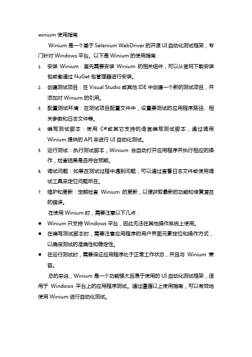
Winium是一个基于Selenium WebDriver的开源UI自动化测试框架,专门针对Windows平台。
以下是Winium的使用指南:
1.安装Winium:首先需要安装Winium的相关组件,可以从官网下载安装
包或者通过NuGet包管理器进行安装。
2.创建测试项目:在Visual Studio或其他IDE中创建一个新的测试项目,并
添加对Winium的引用。
3.配置测试环境:在测试项目配置文件中,设置要测试的应用程序路径、相
关参数和日志文件等。
4.编写测试脚本:使用C#或其它支持的语言编写测试脚本,通过调用
Winium提供的API来进行UI自动化测试。
5.运行测试:执行测试脚本,Winium会自动打开应用程序并执行相应的操
作,检查结果是否符合预期。
6.调试问题:如果在测试过程中遇到问题,可以通过查看日志文件或使用调
试工具来定位问题所在。
7.维护和更新:定期检查Winium的更新,以便获取最新的功能和修复潜在
的错误。
在使用Winium时,需要注意以下几点:
●Winium只支持Windows平台,因此无法在其他操作系统上使用。
●在编写测试脚本时,需要注意应用程序的用户界面元素定位和操作方式,
以确保测试的准确性和稳定性。
●在运行测试时,需要保证应用程序处于正常工作状态,并且与Winium兼
容。
总的来说,Winium是一个功能强大且易于使用的UI自动化测试框架,适用于Windows平台上的应用程序测试。
通过遵循以上使用指南,可以有效地使用Winium进行自动化测试。
MedWin软件使用
目录MedWin 概述 (1)MedWin 集成开发环境的特点 (1)MedWin 对系统的要求 (2)快速入门适用范围 (2)内容安排 (2)一、安装MedWin (3)二、设置MedWin (6)三、MedWin 开发入门 (11)四、MedWin 调试实例 (18)五、MedWin 断点功能 (24)六、MedWin 菜单命令 (26)七、MedWin 右键弹出式菜单 (2)八、MedWin 的表达式 (4)MedWin 概述MedWin 是万利电子有限公司Insight® 系列仿真开发系统的高性能集成开发环境。
集编辑、编译/ 汇编、在线及模拟调试为一体,VC 风格的用户界面,内嵌自主版权的宏汇编器和连接器,并完全支持Franklin/Keil C 扩展OMF 格式文件,支持所有变量类型及表达式,配合Insight® 系列仿真器,是您开发80C51 系列单片机的理想开发工具。
图1:MedWin 集成开发环境窗口界面MedWin 集成开发环境的特点1. 完美的Windows 版集成开发环境MedWin2. 内嵌自主版权的宏汇编器A51 和连接器L51,并支持Keil/Franklin 编译、连接工具3. 具有分别独立控制项目文件的工程项目管理器4. 在工程项目管理下,实现多模块和混合语言编程调试5. VC 风格的窗口停驻、窗口切分和工作簿模式界面6. 在线编辑、编译/ 汇编、连接下载运行和错误关联定位7. 符合编程语言语法的彩色文本显示8. 完全的表达式分析,支持所有数据类型变量的观察9. 无须点击的感应式鼠标提示功能10. 外部功能部件编程向导11. 不限制打开数据区观察窗口的数目12. 调试状态下用户程序自动重装功能13. 提供真实的软件模拟仿真开发环境MedWin 对系统的要求为使MedWin 集成开发环境能够正常地运行,您必须提供以下软硬件环境:1. 586 以上的PC 及兼容机2. 100M 以上的剩余硬盘空间3. 分辨率为800x600 以上的显示器4. 具有SPP 功能的打印机接口5. 中文或英文Windows/95/98,Windows/Me,Windows 2000/NT,Windows XP6. 尽量减少DOS 自动批处理中关于系统路径及环境变量的设置,或删除DOS 下的批处理文件Autoexec.bat 文件快速入门适用范围1. MedWin 集成开发环境V2.3x2. 标准80C51 系列仿真器SE-52P,ME-52A,ME52P,AE-52E3. 标准扩展80C51 系列仿真器ME-52H/SE-52H,ME-32004. 专用80C51 系列仿真器ME-12055. PHILIPS 51LPC 系列仿真器SE-764内容安排本书从以下八部分,介绍MedWin 集成开发环境的快速入门方法:一、安装MedWin二、设置MedWin三、Med Win 开发入门四、MedWin 调试实例五、MedWin 断点功能六、MedWin 菜单命令七、MedWin 右键弹出式菜单八、MedWin 的表达式一、安装MedWin本章分三节介绍怎样获得MedWin 集成开发环境安装程序、MedWin 集成开发环境对系统的要求和安装MedWin 集成开发环境步骤。
MDI,菜单,工具栏,状态栏

MDI
设置为MDI容器
MDI
方法 LayoutMdi 说明
在 MDI 父窗体内排列多文档界面 (MDI) 子 窗体。 用于获取当前活动的多文档界面(MDI)子窗 体。
ActivateMdiChild
事件
MdiChildActivate
说明
在多文档界面 (MDI) 应用程序内激活或关闭 MDI 子窗体时发生。
MDI,菜单,工具,状态栏
MDI
MDI
MDI
注意:
• • • • • • 启动一个MDI应用程序时,首先显示父窗体。 它是应用程序中所有其他窗口的容器。 每个应用程序界面都只能有一个MDI父窗体。 在任何指定的时间都可以打开多个子窗体。 任何MDI子窗体都不能移出MDI框架区域。 关闭MDI父窗体则自动关闭所有打开的MDI子窗体。
效果
ToolStripStatusLabel
ToolStripDropDownButton
ImageList
GripStyle
获取或设置用于重新定位控件的手柄的 可见性。
组成
•StatusStrip控件用于显示应用程序中正在操作的对象的状态 信息及与之相关的信息 ToolStripStatusLabel StatusStrip的组成 ToolStripDropDownButton ToolStripSplitButton ToolStripProgressBar
属性
Checked CheckOnClick DropDownItems
说明
表示该菜单项的复选框是否被选中。 表示是否应在被单击时自动显示为选中或未 选中。 表示该菜单项下的子菜单项集合。
事件
Click
说明
实战教程-Windows Mobile系统使用攻略
如用中国电信1x上网,在网络设置中接入方式选择“中国电信1x”
TV手机电视
d.GPS导航功能
(5).常用软件使用:在首页中,点选主题桌面快捷方式启动器。在启动器中双击相应的程序即可。
操作文档,放在文件浏览器首页中。点选“开始——文件浏览器”,在新页面中找到相应的操作文档,点击打开即可。
4.在手机终端找到拷贝程序所在的文件夹点击程序直接使用或安装即可。
可以选择安装到手机的Extended_ROM(占用手机空间)还是安装在储存卡Storage Card上
安装完成后,在手机的程序菜单中可以找到刚安装的程序。
以.exe为后缀的文件无需安装,直接运行即可。
(4)常见软件使用介绍
本文来源于:安卓游戏下载/
(1)中国电信1x拨号上网设置;
1.首先选择“开始”——“设置”
2.在设置界面选择“连接”
3.在连接界面选择“连接”
4.在新打开页面选择“添加新调制解调器连接”
5.按图示输入名称(任意),图例为中国电信1x,选择调制解调器:在下拉框中选择“电话线路”,选择“下一步”
6.在新界面中文本框中填写:#777,选择“下一步”
与其它手机操作系统的比较:优点:1.界面类似于台式机的Windows,便于熟悉电脑的人操作。
2.预装软件丰富,内置Office Word, Excel, Power Point,可浏览甚至编辑,内置Internet Explorer,Media Player。
3.电脑同步非常便捷,完全兼容Outlook, Office Word, Excel等。
一般安装好程序后,点击“开始——程序”,在打开的页面点击相应的程序即可
如果不需要安装直接可以使用的文件,通常以exe结尾,则直接需要找到该文件所在的目录,点击运行即可。如功能应用“e Gps导航功能”介绍。
Windows_Mobile开发新手入门教程word资料9页
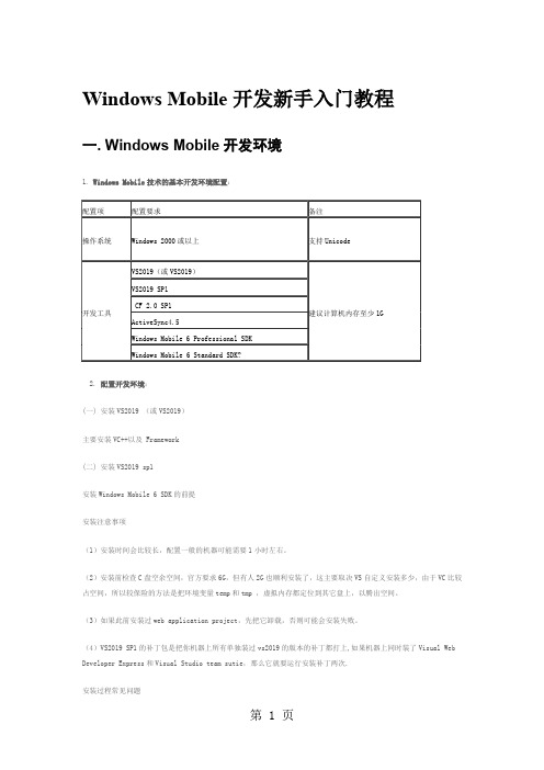
Windows Mobile开发新手入门教程一. Windows Mobile开发环境1. Windows Mobile技术的基本开发环境配置:2. 配置开发环境:(一) 安装VS2019 (或VS2019)主要安装VC++以及 Framework(二) 安装VS2019 sp1安装Windows Mobile 6 SDK的前提安装注意事项(1)安装时间会比较长,配置一般的机器可能需要1小时左右。
(2)安装前检查C盘空余空间,官方要求6G,但有人2G也顺利安装了,这主要取决VS自定义安装多少,由于VC比较占空间,所以较保险的方法是把环境变量temp和tmp ,虚拟内存都定位到其它盘上,以腾出空间。
(3)如果此前安装过web application project,先把它卸载,否则可能会安装失败。
(4)VS2019 SP1的补丁包是把你机器上所有单独装过vs2019的版本的补丁都打上,如果机器上同时装了Visual Web Developer Express和Visual Studio team sutie,那么它就要运行安装补丁两次.安装过程常见问题(1) 数字签名认证的问题在2019或XP安装VS2019 SP1。
可能会收到错误信息:错误 1718。
[FileName]文件被数字签名策略拒绝。
(2)C盘空间的问题提示C盘空间不足,不能成功安装,错误代码2908。
问题解决办法问题(1)的解决办法:1)单击“开始”,单击“运行”,键入secpol.msc,然后单击“确定”。
2)打开“安全设置->软件限制策略”。
注意如果未列出软件限制,右击“软件限制策略”,然后单击“新建策略”。
3)打开“对象类型-->强制”。
4)点选“除本地管理员以外的所有用户”, 并单击“确定”。
5)重新启动计算机。
要点:在执行以上步骤之后,本地管理员就可以安装 .msi 包或 .msp 包。
安装了程序包之后,请按照以上步骤重置强制级别。
C#Windows-SDI和MDI应用程序

C#Windows-SDI和 MDI应用程序
生成MDI应用程序 MDI应用程序至少要由两个截然不同的窗口组成。第一个窗口叫做MDI容器(Container),可以在容器中显示的窗口叫做MDI子窗口。 要把应用程序的主窗口从一个窗体改为MDI容器,只需要把窗体的IsMdiContainer属性设置为true即可。 创建子窗口,add一个新窗体,命名为frmChild,把这个新窗体的MdiParent属性设置为主窗口的一个引用,该窗体就变成子窗口了。
在MDI应用程序可以按最基本窗口,再显示他们。
MDi安装与配置说明windows

M D i安装与配置说明w i n d o w sThe latest revision on November 22, 2020MD3200I 安装与配置说明步骤简介1.连接带外管理口((新设备默认IP为和)2.从光盘安装MDSM3.通过MDSM搜索阵列4.通过MDSM创建磁盘组5.通过MDSM创建虚拟磁盘VD6.主机通过iSCSI Initiator搜索阵列7.通过MDSM加入主机8.通过MDSM映射VD和主机9.主机磁盘管理(刷新、初始化、格式化)1.连接带外管理口一、配置DELL MD3200i存储设备。
1. 将需要对DELL MD3200i存储设备进行初始化调试的计算机与DELL MD3200i 使用(CAT6)连接起来(需先在两头使用TIA/EIA 568B线序做好水晶头)。
可根据实际情况选择连接一个或多个设备,最大可连接32台主机。
2. 右击该计算机的“网上邻居 - > 属性 - > 本地连接 - > 属性 Internet 协议(TCP/IP) - >属性”更改IP地址,使其和设备处于同一网段内(新设备默认IP为和),并Ping通。
注意:配置时所选择的配置计算机的网卡必须为千兆网卡。
2.从光盘安装MDSM二、安装 MDSM(Modular Disk Storage Manager)软件,随机光盘有带,或者从DELL 官方网站下载。
1. 将光盘放入需要安装MDSM(Modular Disk Storage Manager)软件的计算机,等待自动运行或者双击光盘目录里面的程序。
2.在自动弹出安装界面,点击“安装 MD32xxi 存储软件。
3.等待安装程序启动4. 选择语言种类,在这里我们选择“简体中文”,选择好以后单击“确定”按钮。
5. 单击“下一步”按钮6. 阅读许可协议如接受则选择“我接受许可协议的条款”并单击“下一步”按钮,安装继续;如不接受则选择“我不接受许可协议的条款”单击“下一步”按钮安装取消;在这里我们选择“我接受许可协议的条款”进行安装。
windterm使用指南
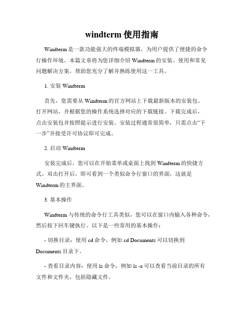
windterm使用指南Windterm是一款功能强大的终端模拟器,为用户提供了便捷的命令行操作环境。
本篇文章将为您详细介绍Windterm的安装、使用和常见问题解决方案,帮助您充分了解并熟练使用这一工具。
1. 安装Windterm首先,您需要从Windterm的官方网站上下载最新版本的安装包。
打开网站,并根据您的操作系统选择对应的下载链接。
下载完成后,点击安装包并按照提示进行安装。
安装过程通常很简单,只需点击“下一步”并接受许可协议即可完成。
2. 启动Windterm安装完成后,您可以在开始菜单或桌面上找到Windterm的快捷方式。
双击打开后,即可看到一个类似命令行窗口的界面,这就是Windterm的主界面。
3. 基本操作Windterm与传统的命令行工具类似,您可以在窗口内输入各种命令,然后按下回车键执行。
以下是一些常用的基本操作:- 切换目录:使用cd命令,例如cd Documents可以切换到Documents目录下。
- 查看目录内容:使用ls命令,例如ls -a可以查看当前目录的所有文件和文件夹,包括隐藏文件。
- 创建文件夹:使用mkdir命令,例如mkdir test可以在当前目录下创建名为test的文件夹。
- 删除文件或文件夹:使用rm命令,例如rm file可以删除名为file的文件,rm -r folder可以删除名为folder的文件夹及其内容。
4. 高级功能Windterm提供了许多高级功能,帮助您更高效地使用命令行。
以下是一些常用的高级功能:- 命令自动补全:在输入命令时,按下Tab键可以自动补全命令或文件名。
这在输入较长的命令或文件路径时特别方便。
- 命令历史记录:使用方向键上下可以快速切换之前执行过的命令。
这对于重复执行一些命令非常有用。
- 多窗口支持:Windterm允许您同时打开多个命令行窗口,可以在不同的目录或任务之间快速切换。
- 快捷键定制:您可以在Windterm的设置中自定义各种快捷键,以适应自己的使用习惯。
windterm使用指南
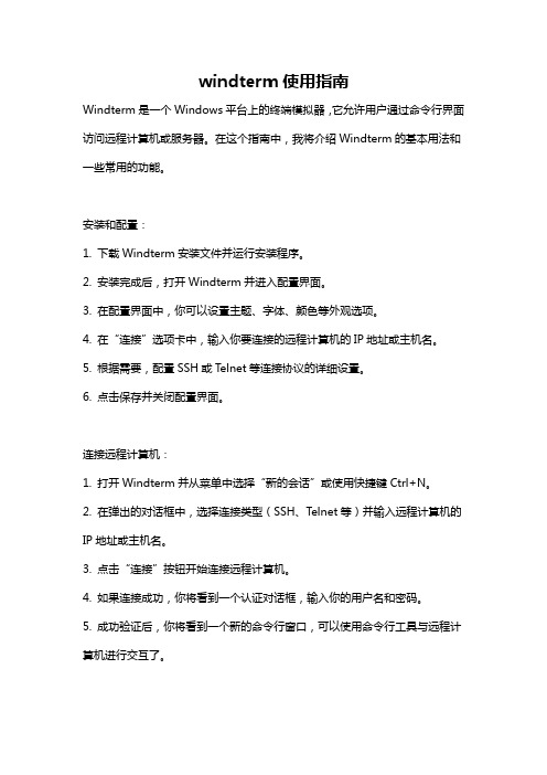
windterm使用指南Windterm是一个Windows平台上的终端模拟器,它允许用户通过命令行界面访问远程计算机或服务器。
在这个指南中,我将介绍Windterm的基本用法和一些常用的功能。
安装和配置:1. 下载Windterm安装文件并运行安装程序。
2. 安装完成后,打开Windterm并进入配置界面。
3. 在配置界面中,你可以设置主题、字体、颜色等外观选项。
4. 在“连接”选项卡中,输入你要连接的远程计算机的IP地址或主机名。
5. 根据需要,配置SSH或Telnet等连接协议的详细设置。
6. 点击保存并关闭配置界面。
连接远程计算机:1. 打开Windterm并从菜单中选择“新的会话”或使用快捷键Ctrl+N。
2. 在弹出的对话框中,选择连接类型(SSH、Telnet等)并输入远程计算机的IP地址或主机名。
3. 点击“连接”按钮开始连接远程计算机。
4. 如果连接成功,你将看到一个认证对话框,输入你的用户名和密码。
5. 成功验证后,你将看到一个新的命令行窗口,可以使用命令行工具与远程计算机进行交互了。
常用命令:1. ls:列出当前目录中的文件和文件夹。
2. cd:改变当前目录。
3. pwd:显示当前工作目录的路径。
4. mkdir:创建新的文件夹。
5. rmdir:删除空的文件夹。
6. cp:复制文件或文件夹。
7. mv:移动或重命名文件或文件夹。
8. rm:删除文件或文件夹。
9. cat:查看文件的内容。
10. grep:在文件中搜索特定的字符串。
11. chmod:修改文件或文件夹的权限。
其他功能:1. 多标签:Windterm允许你在同一个窗口中同时打开多个会话,每个会话通过标签进行管理。
2. 断开连接:在Windterm的菜单栏中,你可以选择断开当前会话,或者断开所有会话。
3. 快速命令:Windterm允许你保存和使用常用的命令,以便快速执行。
4. 自动登录:如果你经常连接到同一个远程计算机,你可以配置自动登录来避免重复输入用户名和密码。
ADi_Winmeil使用手册

Winmeil使用者手冊奕汰科技興業有限公司IDEATEK TECHNOLOGY CO., LTD.TEL:886-2-29081178FAX:886-2-29081229E-mail:idea.tek@Http://一. 系統介紹二. Winmeil 的操作原理三. 量測基礎四. 測針的管制五. 指令種類六. 程式之管控七. 測頭校驗八. 軟體介面說明九. 元素量測十. 計算及兩個元素間的關係十一. WinMeil目錄選擇十二. 基本資料的清除及查看「附錄 一」 WINMEIL功能庫「附錄 二」 WINMEIL快速鍵這資訊包含在這手冊是隨時改變不另行通知。
假如沒有另外詳述,提及任一協會,名字,日期或住址在這手冊出現和其他的例子是純粹地巧合以及用來說明COORD3 產品。
無論如何沒有COORD3許可,不得翻印此手冊。
1994-1997COORD3 軟體辦公室台灣印翻,奕汰科技興業有限公司,版權所有,不得翻印章節 一系統介紹1-1設備內容本系統主要包括-冷凍乾燥機(單向220V)-三次元EOSⅡ主機量測範圍:X mm Y mm Z mm精度: + L/1000μm L=單位一米(溫度要求20±1℃)-直徑25mm校驗球-Renishaw測頭乙套1-2氣源系統三次元量床採用氣壓軸承,必須使用壓縮空氣,進氣壓介於70-85psi,而操作壓力為4 + 0.2 bar,氣源之流向如下:-主管路過濾器:把壓縮空氣中之粉塵及部分水份過濾,故有明顯的排水現象(能過濾至0.3μm)-冷凍乾燥機:把空氣中之絕大部分水份去除,同時空氣出口採用同溫設定,不致在出口處有結霜現象-油霧分離器:把壓縮空氣中之油份排除,以保護量床之氣壓軸承不被油份阻塞(能過濾至0.1μm)1-3電源系統本系統採用單向110V及220V電壓,冷凍乾燥機使用220V之電壓,而主機部分不需另接電源,其所須之電力,由電腦之介面卡供應,而電腦主機、螢幕、喇叭,印表機均採用110電壓,CNC機型為220V AC 單相章節 二 Winmeil 的操作原理WinMeil.ini檔案這WinMeil.ini檔案是負責WinMeil測量軟體的架構。
MDI使用
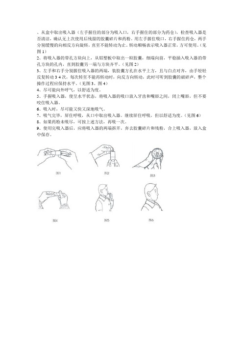
、从盒中取出吸入器(左手握住的部分为吸入口,右手握住的部分为药仓),检查吸入器是否清洁,确认无上次使用后残留的胶囊碎片和药粉。
用左手握住吸口,右手握住药仓,两手分别缓慢的向相反方向旋转,直至不能转动为止。
转动顺畅表示吸入器正常,方可使用。
(见图1)
2、将吸入器的带孔方块向上,从铝塑板中取出一粒胶囊,细端向前,平稳插入吸入器的带孔方块的孔内,直到胶囊另一端与方块齐平。
(见图2)
3、左手和右手分别握住吸入器的两端,装胶囊方孔在水平上方,且与白点对齐,由手轻轻反复转动3-4次,每次转至不能再转动时,向反方向转动,此时可听到胶囊的破碎声,整个操作过程应保持水平。
(见图3、图4)
4、尽可能向外呼气,以舒适为度。
5、手握吸入器,使呈水平状态,将吸入器的吸口放入牙齿和嘴唇之间,闭上嘴唇,但不要咬住吸入器。
6、吸入时,尽可能又快又深地吸气。
7、吸气完毕,屏住呼吸,从口中取出吸入器。
继续屏住呼吸,但以舒适为度。
(见图6)
8、如果药粉未吸尽,可按上述方法,再吸一次。
9、使用完吸入器后,应将吸入器的两端拆开,弃去胶囊碎片和残粉,合上吸入器,放入盒中保存。
- 1、下载文档前请自行甄别文档内容的完整性,平台不提供额外的编辑、内容补充、找答案等附加服务。
- 2、"仅部分预览"的文档,不可在线预览部分如存在完整性等问题,可反馈申请退款(可完整预览的文档不适用该条件!)。
- 3、如文档侵犯您的权益,请联系客服反馈,我们会尽快为您处理(人工客服工作时间:9:00-18:30)。
Introduction to WinMDI 2.8 (J. Trotter 1993-1998)for the Analysis ofFlow Cytometry Listmode Data FilesObjectives of this tutorial:-Open a listmode data file-Create histograms (single, dual, and 3D histograms)-Perform gating-Perform original analysis-Display statisticsGérald GREGORI, Ph.D.Kathy RAGHEB, M.T.(A.S.C.P.)J. Paul ROBINSON, Ph.D.Purdue University Cytometry LaboratoriesHansen Life Sciences Research Building, B050201 S. University Street,West Lafayette, IN 47907-2064,USAe-mail: gregori@ContentsI. How to Install WinMDI 2.8 (1)II. How to Start WinMDI 2.8 (1)III. How to Create a Single-parameter Histogram (3)IV. How to Create Histogram Overlay (5)V. How to Create a Dual-parameter Histogram (6)1. How to create a dotplot (6)2. How to create a Density plot or a Contour Plot (8)3. How to create a 3-dimensional display (10)4. How to change the parameter labels and font (11)5. How to display a title or write annotations on a graph (11)VI. Zoom (12)VII. How to Create and Display Several Graphs on the Screen (13)VIII. Regions and Gates (14)1. Create a region on a 1-parameter histogram (15)2. Create a region on a 2-parameter histogram (16)3. How to create a quadrant (17)4. How to delete, move, or adjust a region (18)5. Create gates (19)IX. Convert a FCS file to a text file (20)1. Convert a data file (20)2. Only convert the data from a gated region (20)X. Display Statistics (21)XI. Work with a Batch File (22)XII. Overview (23)What we like (23)What we dislike (24)Quick Start in 10 steps (25)1. To start WinMDI 2.8 (25)2. To display a 2-parameter histogram (25)3. To create a 3D plot (25)4. To rotate a 3D graph (26)5. To display a new single-parameter histogram (26)6. To create a region (26)7. To create gates (27)8. To display statistics (27)9. To create histogram overlay (28)10. To create 3D view of histograms (28)I. How to Install WinMDI 2.8The Windows Multiple Document Interface software (WinMDI) is freeware designed by J. Trotter (1993-1998; trotter@) to analyze flow cytometric listmode data files. You can download it from the URL /software.html or find it on any of the Purdue CD-Roms. To install WinMDI 2.8 on your computer, just click on the web page link corresponding to your office system (Windows 95/98/NT or Windows3.1/NT 3.x) and open (or save on your computer and install later) the corresponding wm28w95.exe or winmdi28.exe programs. Follow then the instructions.The minimum system requirements are:•Processor: 486/33 + 387 fpu math chip or better with 8 megabytes memory.•Recommended: 486/66 with 16MB RAM or better•Monitor: SVGA 800x600 or 1024x768 recommended.•OS: MS DOS 5.0 or later + MS Windows 3.1 or later, Windows NT, Windows XP, or OS/2•Windows 3.1: Use Microsoft's SMARTDrive or other disk cache program.Hint!I SUGGEST THAT YOU USE LISTMODE DATA FILES WITH 8.3 FORMAT FILE NAMES.II. How to Start WinMDI 2.8To start WinMDI just click on the WinMDI icon on the desktop, or use Start ÆPrograms Æ WinMDI Æ WinMDI.exe. The following screen is displayed.With WinMDI 2.8 it is possible to create single-parameter histograms, dual-parameters histograms (also called cytograms), and even 3D histograms. The WinMDI Display dialog window offers 4 different graph styles (see figures below):plotDotHistogramplotContourplotDensity-Histogram: displays one or more parameters as a frequency distribution (256 or 1024 channels).-Dotplot: displays correlated data from any two parameters at a 256x256 resolution. Each dot corresponds to an event analyzed by the flow cytometer.Of course, several events can occupy the same dot if they have the sameparameter intensities.-Density plot: displays two parameters as a frequency distribution. Color is used to code the different frequencies of events.-Contour plot: like a dotplot, a contour plot displays correlated data from any two parameters, with contour lines joining points of equal elevation(frequency distribution).III. How to Create a Single-parameter HistogramFrom the WinMDI Display dialog window select the “Histogram” style and click the OK button. A new window allows you to navigate to the sample folder where the listmode data file to analyze is recorded.When the file is selected, press OK. The Select Parameters dialog window appears for selection of the parameter to display.Using the scrolling bar, select the parameter you want to display (FS: forward-angle light scatter; SS: right-angle light scatter; Fl1, Fl2, …, Fln: the first, second, and n th fluorescence recorded by the cytometer). Click the “Read” button to display the corresponding histogram.All the parameters are automatically recorded within each listmode data file. You do not need to type them in the software.Hint!S OMETIMES W IN MDI DOES NOT AUTOMATICALLY RECOGNIZE WHICH AMPLIFICATION IS USED (L INEAR OR L OGARITHMIC).Y OU NEED TO SPECIFY THE SCALE BY SELECTING T OOLS ÆS ET L IN L OG TO OPEN THE L IN/L OG V ARIABLES DIALOG WINDOW.T HEN CHECK THE CORRESPONDING SCALE FOR EACH PARAMETER.Very often it is necessary to change the position of the histogram and optimize the size by stretching its different borders and/or corners.In the Select Parameters dialog window scroll bar, the “Show All Parameters” option generates a single graph in which all the histograms of all the different parameters are plotted together. If you click on the graph and select “Format” in the popup menu the Format Histogram dialog window is displayed (see below).Among the available options you can, for instance:•Set the color of each histogram. Just select the corresponding histogram name and select the color (scroll menu). You can fill the histograms withtheir respective color (check the “Solid Fill” check box) or leave themempty (uncheck the box).•Rescale the histograms by changing the “Y Scale” value.•Change the thickness of the lines (change the “Line Width” option);•Display all the histograms in black & white (check the “B+W” check box).•Display all the histogram in 3 dimensions (check the “3D View” check box).•Smooth the histograms.•Set up a logarithmic scale for the vertical axis.•Insert a title (see the “Title” scroll menu).IV. How to Create Histogram OverlayYou can create a histogram overlay using WinMDI 2.8 (see figure below).To create the overlay:1.Create a single-parameter histogram from a listmode data file: open thedata file by clicking FileÆ Open File, then navigate to the file and press OK.Click on the “Histogram” style, and select a parameter. Click on the “Read”button to display the graph.2.In the same way, open a new data file, click on the “Histogram” style,select the same parameter as previously, but click on the “Overlay” button to create the overlay (not the “Read” button). The histogram will be plotted on top of the previous one.You can overlay up to 12 histogram parameters on the same graph. You can also change the color of the different histograms using the Format Overlay dialogue window (click on the graph and select “Format” in the popup menu. The “Histogram Control” box is for making changes to the original, or first histogram. The “Overlays” box is for making changes to the histograms overlaid on top of the original histogram.V. How to Create a Dual-parameter HistogramIf you decide to plot first a dual-parameter histogram, you need to choose which style of plot you want to draw from the three different styles displayed in the WinMDI Display dialog window: a dotplot, a density plot, or a contour plot.1. How to create a dotplotSelect the “Dotplot” option in the WinMDI Display window and click the OK button. In the Open Dotplot window navigate in the folders and select the listmode data file you want to analyze. Press the OK button. The following window appears on the screen:Different options are displayed in order to create the dotplot.•The name of the listmode data file is automatically displayed at the top of the window.•Just below the filename, the user can select which parameter to display on the x axis and which one on the y axis. When selected, these two parametersappear in the “Parameter” box. To the right of this box, the “Amplifier/Scale”box display different possible scales for the axes. Select the first parameter(ex: FS on the previous figure) and then select the corresponding scale. Select“Linear” if this parameter has been recorded in linear mode. If this parameterhas been recorded in logarithmic scale, then select the number of decadescorresponding to the flow cytometer protocol setup (3 or 4 decades). Repeatall these steps for the second parameter.•In the “Plot Number of Events” area, different options are available in order to display 2000 events only, or half, three quarters or all the events recorded.You can also set a specific number of events (type the value).•In the “Draw Option” area are 6 check boxes. The first three are related to kinetics analyses where the intensity of one or several parameters is monitoredwith the time.The “Show XY Labels” check box needs to be checked in order to label theaxes.The “Color 2D Regions” check box needs to be checked to color the eventsgated on a histogram. Gating and coloring events can be used simultaneouslyin order to localize on one or several histograms the events gated in anotherhistogram. For more detail see VII. Regions and Gates.•The “Log Grid 3D” check box is dedicated to histograms displaying three parameters at the same time. If this box is checked, a grid is applied on thedifferent axes to underline the logarithmic scale. Of course this grid concernsonly parameters acquired in the logarithmic scale.Six buttons are also available on the “Format Dotplot” window.Click the “OK” button to close the window when all the desired options have been selected.The “Cancel” button closes the “Format Dotplot” window without taking into account the selected options.The “Gates” button opens the Gate List dialog box in order to handle regions or gates (see VII. Regions and Gates).The “New File” button allows you to change the listmode data file to work with.The “3D Plot” is used to convert the current dual-parameter histogram into a 3-dimensional histogram. When this button is clicked the Select xyz dialog window appears. You can choose the three parameters to display. To select a parameter either double-click on it or select it and press the “>>” button. When a parameter is selected it islisted in the right X, Y, and Z Parameters box. To remove or change one or all the parameters click the “Reset” button. When the three parameters are selected press the “OK button.”The “Abort” button aborts the 3D transformation.The “Help” button opens the WinMDI 2.8 help.2. How to create a Density plot or a Contour PlotThese graphs are very useful to identify the borders between several close clusters. In the WinMDI Display dialog windows select the “Density Plot” or “Contour Plot” option and click the OK button.In the new Open Dotplot dialog window, navigate in the folders and select the listmode data file you want to analyze. Press the OK button.Whatever option is selected, the Format 2D Display dialog window appears on the screen. In fact it is not exactly the same window. Indeed, there is one difference: the “Density Plot” check box is checked only in the case of a density plot (see figure below). Later on, it is possible to shift from the density plot to the contour plot just by checking this box or not.Contour Plot:Density Plot:The Format 2D Display dialog window displays several pieces of information on the graph.•The name of the listmode data file is automatically displayed in the topleft corner.•You can choose which parameters to display (X and Y parameters), thetype of amplification (linear, or logarithmic), and the resolution.•Check the “Density Plot” check box to draw a density plot histogram.•Check “Label Axes” in order to label the two axes.•The “Color” check box is used to display the different densities of eventsaccording to a color code set up automatically (check the “Calculate Colors”check box) or by the user (uncheck the “Calculate Colors” check box andchoose a color through the “Display Colors” menu).Hint!I SUGGEST THAT YOU LET THE SOFTWARE HANDLE THE COLOR CALCULATION AND THE DIFFERENT OPTIONS DISPLAYED ON THE RIGHT OF THE WINDOW (C ONTOUR).L ATER ON, IT IS ALWAYS POSSIBLE TO CALL UP THIS WINDOW AND CHANGE SOME OPTIONS IN ORDER TO SMOOTH THE DENSITY OR THE CONTOUR LINES, TO SET UP A THRESHOLD, TO CHANGE THE THICKNESS OF THE LINES, TO SELECT ANOTHER ALGORITHM TO SET UP THE CONTOUR OR DENSITY PLOT, ETC.Hint!I T IS ALSO POSSIBLE TO CREATE A 3D HISTOGRAM BY CHECKING THE “S HOW 3D D ISPLAY” CHECK BOX.T HE DENSITY OF EVENTS WILL BE PLOTTED ON THE THIRD AXIS.I T IS THEN POSSIBLE TO COLOR ON THIS 3D HISTOGRAM THE EVENTS WHICH WOULD HAVE BEEN GATED ON THE 2D HISTOGRAM BY CHECKING THE “U SE R EGION C OLORS” CHECK BOX.I T IS POSSIBLE TO CHOOSE THE COLOR USING THE “S ET 3D F ILL C OLOR” MENU.I T IS ALSO POSSIBLE TO CHANGE THE ORIENTATION OF THE 3D DISPLAY BY CHANGING THE “R OTATION” ANGLE AND/OR THE “T ILT” AND “D ISTANCE” VALUES.Five buttons are also available on the Format 2D Display dialog window.- Click the “OK” button to close this window and display the graph when all the desired options have been selected.- Click the “Cancel” button to close the dialog window without taking into account the last changes.- The “Gates” button opens the “Gate List” dialog box and defines the regions or gates (see VII. Regions and Gates).- Click the “New File” button to select another listmode data file.- The “Help” button opens the WinMDI help file.3. How to create a 3-dimensional displayIt is possible to transform any histogram, dot plot, density plot, or contour plot into a 3D graph displaying three different parameters. A left click anywhere on the graph shows a new menu. A left click on the “Format” option opens the Histogram Format, Dot Plot Format, or Format 2D Display dialog window respectively for a histogram, a dot plot, or a density (or contour) plot. To display the 3D graph just check the “3D view” or “Show 3D Display” check box and press OK, or press the “3D Plot” button. These steps are reversible and it is thus possible to come back to a 2D graph.It is possible to change the orientation of the 3D graph using the mouse. Just press the Ctrl key on your keyboard and at the same time click the mouse on the graph. The graph changes and displays then only an empty cube without any labeling (see below).Just keep clicking the Ctrl key and the left mouse button and drag the mouse to change the orientation of the graph. When the desired orientation is reached, release the mouse button to display the graph.4. How to change the parameter labels and fontWinMDI automatically labels the axes of the graphs. The default labels are those recorded in the listmode data file. To set new label(s), select in the tool bar Tool ÆParameter Labels (or press Alt+L) to open a dialog window. Type the new label(s), check the “Use these instead of file labels” check box, and press the OK button.To change the font press F8 or select in the tool bar Window Æ Set Defaults ÆFont.Select the font, the style, the size, the effects, and the color. Click the OK button.5. How to display a title or write annotations on a graphYou can write a title on each graph and add comments. Select in the tool bar Tools Æ Annotate (or press Alt+A) to open the Annotation dialog window. Type the text or the title in the “Text” box. Choose the font, size, and style and press the OK button. Then move the mouse cursor and click with the left mouse button where you want to display the text.You can move, modify or delete the annotation at any time.- To move the text: just click on it and drag it.- To modify the text: keeping the “shift” key pressed, double click on theannotation then type the new text and press “Enter”.- To delete an annotation or a title: keeping the “shift” key pressed, doubleclick on the annotation to select it and press the “Delete” key.VI. ZoomIt is possible to magnify a particular area on any plot:-Click with the right-button of the mouse on the plot of your choice and move the mouse in order to define the area to zoom in.-Click with the left button of the mouse within the defined area. In the pop up menu click on Zoom.To unzoom, click with the left button of the mouse anywhere in the plot and in the pop up menu select Unzoom.Zooming and unzoming can be performed several times on the same plot.VII. How to Create and Display Several Graphs on the ScreenTo create a new graph once the first graph has been displayed, select in the tool bar the “Display” button and choose which type of graph you want to draw. Then repeat the previous steps to select the listmode data file to open and to define the settings of the graph.When all the graphs are displayed, it is possible to resize them, to move them one by one, or to reorganize them automatically using the Windows button in the tool bar.The Windows Æ Cascade option superimposes the different graphs on top of each other and only the first one is visible. The Windows Æ Tile option shares the screen between the different graphs which are thus all visible.R1 R2Several other options also allow the user to Minimize All, Restore All, and Close All graphs.Hint!T O CREATE A NEW GRAPH WHEN ALL THE PREVIOUS GRAPHS ARE CLOSED, CLICK F ILE ÆO PEN F ILE, CHOOSE THE TYPE OF GRAPH TO DISPLAY, AND THEN NAVIGATE TO THE FILE TO OPEN.VIII. Regions and GatesNow that you’ve learned how to open a listmode data file and display the main graphs, you need to learn how to create regions and gates. A region can be defined as set of points carefully selected by the user that determine an area on a graph.One or several regions can be defined on the same graph (see Figure below).The regions have to be distinguished from the gates. Gates are Boolean expressions containing one or several regions. So a gate can be equal to a region, but this is not always the case.The regions are used to compute statistics for the subset of events selected by the user in a peculiar histogram. Moreover, this cluster can then be gated and its events colored on the other graphs.WinMDI offers 4 different region styles. The “Histogram” region can be drawn only on a one-parameter histogram plot. The three other styles (“Polygon,” “SortRect,” and “Ellipse”) can be applied to any two-parameter graph.No region can be directly drawn on 3D graphs.1. Create a region on a 1-parameter histogramTo create a “Histogram” region click the left mouse button on the histogram graph where you want to draw the region. A popup menu will appear. Select “Regions” to open the 2D Regions Tool dialog window. Sixteen regions from R1 to R16 (R means region) are then listed with different colors. The events contained in a region will be colored. To change the color, click on the color and select another one. Select the “Histogram” region style (it should already be selected). Click the “Create” button. The Set Region Tool dialog window appears. On the histogram click with the left mouse button where you want to set up the lower (left) limit of your region. Then click with the right mouse button where you want to set up the upper (right) limit of the region. You have just created a marker (labeled from M1 to M8).The lower and upper limits are displayed on the Set Region Tool dialog window. To transform a marker into a region (labeled R + a number) just press the “Create Region from Current Marker” button. To erase the marker just double-click with the right mouse button on it.You can create other regions on the same histogram by creating a second marker. Just change the marker index and create a new marker on the histogram. Create a second region from this second marker. You can create up to 8 different markers or regions on the same histogram.Hint!Y OU CAN ALSO GENERATE MARKERS WITHOUT GENERATING A REGION TO GET STATISTICS, BUT IN THAT CASE THE EVENTS CANNOT BE GATED ON THE OTHER GRAPHS.T O CREATE A MARKER JUST CLICK THE LEFT MOUSE BUTTON ON THE HISTOGRAM AND SELECT “M ARKERS” IN THE POPUP MENU.T HEN PLACE THE LOWER AND UPPER LIMITS OF THE MARKER AS PREVIOUSLY DESCRIBED.2. Create a region on a 2-parameter histogramOn a 2-parameter histogram you can draw three different region styles. Click the left mouse button on the graph where you want to draw the region. A popup menu appears. Select “Regions” to open the 2D Regions Tool dialog window. Select the region style: Polygon, SortRect, or Ellipse (see figure below).Polygon Style SortRect and Ellipse StylePolygon StyleThe polygon style allows you to draw a polygonal region. Click on the graph where you want to start your region. You just defined the first point in the region. If you release the mouse button and move the mouse to a different position you will see a segment connecting the first point to your mouse pointer. Click to set up the second point in the region. Continue to move the mouse and click when you want to define a new point in the region. To close the region, you need to click on the first point.SortRect and Ellipse StylesThe SortRect style allows you to draw a rectangular (or square) region. Click on the graph where you want to set the upper left corner of the region. Then keep the left mouse button pressed and move the mouse to draw the region. The region appears as a dashed line. When the region is correctly drawn, release the mouse button.The ellipse style allows you to draw an elliptical (or circular) region. To draw such a region just processed as for the rectangular region.3. How to create a quadrantA quadrant can be used only in bivariate displays. Quadrant divides a graph into 4 regions: upper left (labeled UL), upper right (UR), lower left (LL) and lower right (LR).To create a quadrant, click on a graph and select “Quadrant” in the popup menu.The 4 regions are displayed. To adjust the size and the localization of the regions youClick here to select and move the quadrantneed to activate the quadrant and then click where you want to display its center. To select the quadrant, you can double-click the center of the quadrant or press Alt+Q or click the “Tools” button in the main tool bar and select “Quadrant Tool.”The quadrant position is used by WinMDI to calculate statistics within each of the four regions. The statistics can be displayed in the “Stats” window.The percentage of events gated in each region is also displayed in each corner of the graph.4. How to delete, move, or adjust a regionTo delete a regionTo delete a region, click on any graph with the left mouse button. In the popup menu select “Regions” to open the 2D Regions Tool dialog window. Select the region to delete (check its check box) and press the “Delete” option button. Close the dialog window. You can delete only one region at a time.Hint!S OMETIMES THE DELETED REGION IS STILL DISPLAYED ON THE GRAPH.T O CORRECT THIS ARTIFACT CLICK ON THE TOOL BAR W INDOW ÆR EFRESH A LL(OR PRESS A LT+E ND).To change the localization of a region or resize a regionFor a 1-parameter histogram it is easier to delete the region and to draw a new one in the right localization.For any 2-parameter graph (dot plot, density plot, or contour plot) the way regions are resized or moved is common to all region styles. To move a region, double-click on the region to select it and drag it to its new location. You can also move the label without moving the region. Just double click in the region to activate it, click on the label and drag it where you want. When done, release the mouse button.To resize a region, double click on the region to display the size handles. Click on the handles and drag them to adjust the size of the region.5. Create gates“Gates” are Boolean expressions containing one or several regions. They are defined using the different logical operators AND, OR, and NOT to combine the different regions. But gates are not manually drawn like regions.To define a gate on a graph, click on the graph and in the popup menu select “Gates” to open the Logical Gate Tool dialog window (see figure below).The Logical Gate Tool dialog box consists of two lists. On the left part is the list of all the existing regions (R1, R2, etc.). On the right is the list of the logical operators.To create a gate on the graph, you need to assign each necessary region with its correct logical operator.When you select only one region, for instance R1, and the logical operator AND, this means that all the events of the region R1 will be gated on the graph and displayed. But if you also select the Region R2, and select also the AND operator for this region, then only the events which are in both R1 and R2 will be gated and displayed.If we take the same example with the operator OR, then the events which are in R1 only, or in R2 only, or in both R1 and R2 will be gated and displayed.The operator NOT must be used to gate the events of a region that you do not want to display. This is particularly useful when you want to get the statistical results of a cluster of events mixed with another cluster on the same graph (let’s say forward scatter vs side scatter). You can create a region around the “not desirable events” on another graph where your clusters are well separated (for instance fluorescence collected onPMT1 vs Side Scatter) and thus gate them out of the forward scatter vs right scatter graph.All regions not necessary to define your gate need to have the OFF logical operator selected.IX. Convert a FCS file to a text file1. Convert a data fileWith WinMDI you can convert a FCS file into a text format. The data can thus be read by another software for further analysis beyond that of the regular flow cytometry software.To convert an entire FCS data file, click on FileÆSave As, then :-Select Tabbed Text from the file type list box,-Under File Name type in the new file name,-Click on Save.Hint!Under Preferences you can choose if the text must correspond to the channel value (if you work in linear scale) or to the arithmetic value (for log parameters).2. Only convert the data from a gated regionDraw the region(s) you need to perform your gating and display only the cells of interest. The shape of the region(s) does not matter for converting the data. Click on File ÆSave As, then :-Select Tabbed Text from the file type list box,-Under File Name type in the new file name,-Click on Save.X. Display StatisticsYou can display the statistics for any and all regions in WinMDI in the Stats window. To create the Stats window, click on a graph and select the “Stats” option. This window already contains certain information (file name, date, etc.) and some statistics. In the tool bar of this window click the “Format” button in order to open the Edit Statistics dialog window. This new window lists the different information that can be displayed in the Stats window. To select a field just check the corresponding check box, to unselect one just uncheck the check box.The different statistics you can display for each region are:•File name•Sample ID/Title•Date•Cytometer•% Total events•% Gated events•Markers•Events•Mean/CV•Geometric log means•Median•Peak channel value•Parameters•Range•Use Tabbed FormatWhen the statistics are displayed you can use the tool bar buttons of the Stats window to perform different operations:You can update the statistics (press the “Update” button) each time you move, remove, or create a region on a graph;You can save the statistics in a text format (.txt) in a new file, in order to read them with different software (press the “SaveAs” button). This new file can benamed as you want: just type a new name instead of the default “statfile.txt”name.You can also print the statistics (press the “Print” button).The “Owner” button is used to show you on which graph you clicked to create the “Stats” window.。