6704板卡结构图
CISCO交换机安装手册【板卡】
C H A P T E R2-1Cisco 7600 Series Routers Module GuideOL-9392-032Ethernet and Gigabit Ethernet Switching ModulesThis chapter describes the Ethernet and Gigabit Ethernet switching modules, and it contains these sections:•10/100 and 10/100/1000 Ethernet Switching Modules, page 2-1•Gigabit Ethernet Switching Modules, page 2-13•Ethernet Module LEDs, page 2-2210/100 and 10/100/1000 Ethernet Switching ModulesNoteSpecific combinations of supervisor engines and modules may not be supported in your chassis. Refer to the release notes for the software version running on your system for specific information on modules and supervisor engine combinations that are not supported.This section describes these 10/100 and 10/100/1000 Ethernet switching modules:•24-Port 10BASE-FL Ethernet Switching Module (WS-X6024-10FL-MT), page 2-4•48-Port 10/100/1000BASE-T Ethernet Switching Module (WS-X6148-GE-TX), page 2-4•48-Port 10/100/1000BASE-T Ethernet Switching Module (WS-X6148V-GE-TX), page 2-4•48-Port 10/100BASE-T Ethernet Switching Module (WS-X6148-RJ21V), page 2-5•48-Port 10/100BASE-T Ethernet Switching Module (WS-X6148-RJ45V), page 2-6•24-Port 100BASE-FX Ethernet Switching Module (WS-X6224-100FX-MT), page 2-6•48-Port 10/100BASE-T Ethernet Switching Module (WS-X6248-RJ45), page 2-7•48-Port 10/100BASE-T Ethernet Switching Module (WS-X6248-TEL), page 2-7•48-Port 10/100BASE-T Ethernet Switching Module (WS-X6248A-TEL), page 2-7•24-Port 100BASE-FX Ethernet Switching Module (WS-X6324-100FX-MM), page 2-8•24-Port 100BASE-FX Ethernet Switching Module (WS-X6324-100FX-SM), page 2-8•48-Port 10/100BASE-T Ethernet Switching Module (WS-X6348-RJ21V), page 2-9•48-Port 10/100BASE-T Ethernet Switching Module (WS-X6348-RJ-45), page 2-9•48-Port 10/100BASE-T Ethernet Switching Module (WS-X6348-RJ45V), page 2-10Cisco 7600 Series Routers Module GuideOL-9392-03Chapter 2 Ethernet and Gigabit Ethernet Switching Modules10/100 and 10/100/1000 Ethernet Switching Modules•24-Port 100BASE-FX Fabric-Enabled Ethernet Switching Module (WS-X6524-100FX-MM), page 2-10•48-Port 10/100/1000BASE-T Ethernet Switching Module (WS-X6548-GE-TX), page 2-11•48-Port 10/100/1000BASE-T Ethernet Switching Module (WS-X6548V-GE-TX), page 2-11•48-Port 10/100BASE-T Fabric-Enabled Ethernet Switching Module (WS-X6548-RJ-21), page 2-12•48-Port 10/100BASE-T Fabric-Enabled Ethernet Switching Module (WS-X6548-RJ-45), page 2-12•48-Port 10/100/1000BASE-T Fabric-Enabled Ethernet Switching Module (WS-X6748-GE-TX), page 2-13Table 2-1 lists the features of the Ethernet switching modules.T able 2-1Ethernet Switching Modules FeaturesProduct Number Backplane Connection Forwarding Inline Power 1Port Buffer Size Queues Per Port WS-X6024-10FL-MT 32 Gbps Bus Centralized No 128 KB 2 transmit,1 receive WS-X6148-GE-TX 32 Gbps Bus Centralized Optional 2128 KB 2 transmit,1 receive WS-6148V-GE-TX 32 Gbps Bus Centralized Yes 128 KB 2 transmit,1 receive WS-X6148-RJ21V 32 Gbps Bus Centralized Yes 128 KB 2 transmit,1 receive WS-X6148-RJ45V 32 Gbps Bus Centralized Yes 128 KB 2 transmit,1 receive WS-X6224-100FX-MT 32 Gbps Bus Centralized Yes 128 KB 2 transmit,1 receive WS-X6248-RJ-4532 Gbps Bus Centralized No 128 KB 2 transmit,1 receive WS-X6248-TEL 32 Gbps Bus Centralized No 128 KB 2 transmit,1 receive WS-X6248A-TEL 32 Gbps Bus Centralized No 128 KB 2 transmit,1 receive WS-X6324-100FX-MM 32 Gbps Bus Centralized No 128 KB 2 transmit,1 receive WS-X6324-100FX-SM 32 Gbps Bus Centralized No 128 KB 2 transmit,1 receive WS-X6348-RJ21V 32 Gbps Bus Centralized Yes 128 KB 2 transmit,1 receive WS-X6348-RJ-4532 Gbps Bus Centralized Optional 2128 KB 2 transmit,1 receive WS-X6348-RJ45V32 Gbps BusCentralizedYes128 KB2 transmit,1 receiveCisco 7600 Series Routers Module GuideOL-9392-03Chapter 2 Ethernet and Gigabit Ethernet Switching Modules10/100 and 10/100/1000 Ethernet Switching ModulesWS-X6524-100FX-MMSwitch Fabric and BusCentralized Supportsoptional DFC card No1 MB4 transmit,2 receiveWS-X6548-GE-TX Switch Fabric and Bus Centralized Optional 2 1 MB 4 transmit,2 receive WS-6548V-GE-TX Switch Fabric and Bus Centralized Yes 1 MB 4 transmit,2 receive WS-X6548-RJ-21Switch Fabric and BusCentralized Supportsoptional DFC card No1 MB4 transmit,2 receiveWS-X6548-RJ-45Switch Fabric and BusCentralized Supportsoptional DFC card No 1 MB4 transmit,2 receiveWS-X6748-GE-TXSwitch Fabric CEF720No 1.3 MB4 transmit,2 receive1.Supports IP phones.2.Supports an optional inline power field upgrade module (WS-F6K-VPWR=)T able 2-1Ethernet Switching Modules Features (continued)Product Number Backplane Connection Forwarding Inline Power 1Port Buffer Size Queues Per Port2-4Cisco 7600 Series Routers Module GuideOL-9392-03Chapter 2 Ethernet and Gigabit Ethernet Switching Modules10/100 and 10/100/1000 Ethernet Switching ModulesNote2-5Cisco 7600 Series Routers Module GuideOL-9392-03Chapter 2 Ethernet and Gigabit Ethernet Switching Modules10/100 and 10/100/1000 Ethernet Switching Modules2-6Cisco 7600 Series Routers Module GuideOL-9392-03Chapter 2 Ethernet and Gigabit Ethernet Switching Modules10/100 and 10/100/1000 Ethernet Switching ModulesNote2-7Cisco 7600 Series Routers Module GuideOL-9392-03Chapter 2 Ethernet and Gigabit Ethernet Switching Modules10/100 and 10/100/1000 Ethernet Switching Modules2-8Cisco 7600 Series Routers Module GuideOL-9392-03Chapter 2 Ethernet and Gigabit Ethernet Switching Modules10/100 and 10/100/1000 Ethernet Switching ModulesNoteNote2-9Cisco 7600 Series Routers Module GuideOL-9392-03Chapter 2 Ethernet and Gigabit Ethernet Switching Modules10/100 and 10/100/1000 Ethernet Switching Modules2-10Cisco 7600 Series Routers Module GuideOL-9392-03Chapter 2 Ethernet and Gigabit Ethernet Switching Modules10/100 and 10/100/1000 Ethernet Switching ModulesNote2-11Cisco 7600 Series Routers Module GuideOL-9392-0310/100 and 10/100/1000 Ethernet Switching Modules2-12Cisco 7600 Series Routers Module GuideOL-9392-0310/100 and 10/100/1000 Ethernet Switching Modules2-13Cisco 7600 Series Routers Module GuideOL-9392-03Gigabit Ethernet Switching ModulesCisco 7600 Series Routers Module GuideOL-9392-03Gigabit Ethernet Switching ModulesT able 2-2Gigabit and 10-Gigabit Ethernet Switching Modules FeaturesProduct Number Backplane Connection Forwarding Number of Transmit Queues/Port Number of Receive Queues/Port WS-X6316-GE-TX Bus Centralized 32WS-X6408-GBIC Bus Centralized 32WS-X6408A-GBIC Bus Centralized 32WS-X6416-GBIC Bus Centralized 32WS-X6416-GE-MT BusCentralized32WS-X6501-10GEX4Switch fabric and busCentralized. Support for distributed forwarding with optionaldistributed forwarding card (DFC)32WS-X6502 -10GESwitch fabric and bus Centralized. Support for distributed forwarding with optional DFC 32WS-X6516-GBIC Switch fabric and bus Centralized. Support for distributed forwarding with optional DFC 32WS-X6516A-GBIC Switch fabric and bus Centralized. Support for distributed forwarding with optional DFC 32WS-X6516-GE-TX Switch fabric and busCentralized. Support for distributed forwarding with optional DFC32WS-X6704-10GESwitch fabric 1(dual channel)1.The module can be installed in slots 2–6 in the Cisco 7606, slots 2–9 in the Cisco 7609 and OSR-7609, and slots 9–13 in the Cisco7613 routers. It cannot be installed in slots 2–8 of the Cisco 7613 router. The module requires a Supervisor Engine 720.Centralized. Support for distributed forwardingwith optional DFC 3222.Receive queues change depending on whether you have a centralized forward card (CFC) or a DFC. For information about queuestructures, see /en/US/docs/routers/7600/ios/12.2SXF/configuration/guide/qos.html#wp1666010.WS-X6724-SFPSwitch fabricCentralized. Support for distributed forwarding with optional DFC 322WS-X6748-SFP Switch fabricCentralized. Support for distributed forwarding with optional DFC322WS-X6816-GBIC Switch fabric 1 (dual channel)Distributed forwarding with integrated DFC 32WS-X6708-10G-3C Switch fabric Distributed forwarding with integrated DFC 882WS-X6708-10G-3CXLSwitch fabricDistributed forwarding with integrated DFC8822-15Cisco 7600 Series Routers Module GuideOL-9392-03Gigabit Ethernet Switching ModulesNoteNote2-16Cisco 7600 Series Routers Module GuideOL-9392-03Gigabit Ethernet Switching ModulesNoteNote2-17Cisco 7600 Series Routers Module GuideOL-9392-03Gigabit Ethernet Switching Modules2-18Cisco 7600 Series Routers Module GuideOL-9392-03Gigabit Ethernet Switching ModulesNoteNote2-19Cisco 7600 Series Routers Module GuideOL-9392-03Gigabit Ethernet Switching Modules2-20Cisco 7600 Series Routers Module GuideOL-9392-03Gigabit Ethernet Switching ModulesNoteNote2-21Cisco 7600 Series Routers Module Guide OL-9392-03Gigabit Ethernet Switching Modules2-22Cisco 7600 Series Routers Module Guide OL-9392-03Ethernet Module LEDsCisco 7600 Series Routers Module Guide OL-9392-03Ethernet Module LEDs LINK GreenThe port is active (the link is connected and operational).OrangeThe module or port is disabled through the CLI command or the module is initializing 1. FlashingorangeThe port is faulty and has been disabled.Off The port is not active or the link is not connected.PHONE Green The voice daughter card is installed.OffThe voice daughter card is not detected or is not installed.1.This is a good time to verify that all LINK LEDs are functioning.T able 2-3Ethernet and Gigabit Ethernet Module LEDs (continued)LEDColor/State DescriptionEthernet Module LEDsCisco 7600 Series Routers Module GuideOL-9392-03。
NI板卡数据手册
Back to TopBack to Top| | Print E-mail this Page Open Document as PDFLast Revised: 2011-02- 25 15:53: 58.0High- Speed Voltage Output – Up to 1 MS/s/Channel, up to 16 Bits, up to 32 ChannelsLow-cost arbitrary waveform generation and high- channel density Integrated multidevice synchronization bus Digital triggering and external clocking Simultaneous updates8 digital I/O lines (TTL/CMOS)Two 24- bit counter/timersMeasurement services that simplify configuration and measurementsOverviewNI 67xx high- speed voltage output devices combine the latest in PC technologies to deliver simultaneous, multichannel updates for control and waveform output applications. Use these modules in a variety of applications, including stimulus- response, power supply control, high- speed, deterministic control, and sensor/signal simulation.Requirements and CompatibilityOS InformationWindows 2000/XP Windows Vista x64/x86Linux®Mac OS X Windows NTDriver InformationNI-DAQmxSoftware CompatibilityVisual C++Visual Studio . NETComparison TablesFamilyBusAnalog OutputUpdate Rate per Channel(S/s)Output ResolutionOutput Range(V)External Voltage ReferenceDigital I/OCounter/Timers TriggeringNI 6711PCI, PXI 41M 12±10yes 82, 24-bit Digital NI 6713PCI, PXI 8740 k to 1M 12±10yes 82, 24-bit Digital NI 6715PCMCIA 8100 k to 1M 12±10yes 82, 24-bit Digital NI 6722PCI, PXI8182 to 800 k13±10no82, 24-bitDigitalNIBack to Top6723PCI, PXI 3245 to 800 k13±10no 82, 24-bit Digital NI 6731PCI 41M 16±10yes 82, 24-bit Digital NI 6733PCI, PXI8740 k to 1M13±10yes82, 24-bitDigitalApplication and TechnologyFeaturesThe versatile NI high- speed voltage output devices commonly replace several kinds of instruments including stand- alone proportional integral derivative (PID) controllers, low-speed arbitrary waveform generators, and function generators.Waveform GenerationThese devices are capable of updating at rates up to 1 MS/s, giving you the ability to generate waveforms up to 500 kHz. When using these devices, you have complete control of each data point that is updated on the output for each channel. This feature is significant because you can define not only common waveforms such as square, sine, or sawtooth but also complex waveforms. For instance, you are able to create a sine wave that is overlaid with noise in which the amplitude and noise shape are user- defined. In practice, the waveform is defined in a software buffer, within PC memory, and is streamed to the voltage output device using direct memory access (DMA) data transfers. Using DMA transfers,the amount of memory located on board the voltage output device is minimized and swapped with inexpensive PC memory.Real- Time ControlYou can use NI high- speed voltage output devices with the NI LabVIEW Real- Time Module to deliver real- time, deterministic control loop execution. Because they arecompatible with LabVIEW Real- Time, common control algorithms such as PID are simple to implement but, more importantly, you may prototype and implement complex, cutting-edge control algorithms as well. High- performance control, on the order of eight PID loops running in excess of 20 kHz each, is possible with this combination of hardware and software. Each high- speed voltage output device offers multichannel simultaneous updates and hardware- timed single- point updates.Multidevice SynchronizationEach high- speed voltage output device offers the ability to be master or slave of a multidevice timing and triggering system. Use integration technologies such as the RTSI bus,PXI trigger bus, and PFI pins to trigger and synchronize to a wide variety of I/O types. These I/O types range from analog input, image acquisition, motion control, and high- speed digitizers to multifunction data acquisition devices. With these integration infrastructures, you can create powerful, custom test and control systems with ease.Measurement Services SoftwareNational Instruments measurement services software, built around NI-DAQmx driver software, features intuitive application programming interfaces, configuration tools, I/O assistants, and other tools designed to reduce system setup, configuration, and development time. This software,part of your data acquisition purchase, includes helpful features such as:Automatic code generation – The DAQ Assistant is an interactive guide that helps you navigate through configuring, testing, and programming analog output tasks and automatically generates the necessary code for NI LabVIEW, LabWindows/CVI, and Measurement Studio software.Cleaner code development – Basic and advanced software functions have been combined into one easy-to- use yet powerful set to help you build cleaner code and move from basic to advanced applications without replacing functions.High- performance driver engine – NI- DAQmx delivers maximum I/O system throughput with a multithreaded driver.Test panels – With the NI Measurement & Automation Explorer (MAX) configuration utility, you can test all of your module functionality before you begin development.Scaled channels – Easily scale your voltage data into the proper engineering units using the NI- DAQmx measurement- ready virtual channels by choosing from a list of common sensors and signals or creating your own custom scale .LabVIEW integration – All NI-DAQmx functions create the waveform data type, which carries acquired data and timing information directly into more than 400 LabVIEW built-in analysis routines for display of results in engineering units on a graph.NI-DAQmx Base DriverNI-DAQmx Base (available at ) offers Mac OS X and Linux users a programming interface similar to NI- DAQmx. It features ready-to- use LabVIEW VIs and C ni. com/downloads function features similar to those included in NI- DAQmx driver software.NI DAQCard- 6715 Hardware Block DiagramNI 671x and NI 673x Hardware Block DiagramNI 672x Hardware Block DiagramHigh- Speed Voltage Output Cables and Accessories Recommended ConfigurationsShielded options for minimal noise interferenceDirect connectivity options such as BNCLow-cost options for OEMFront- mount terminal block for PXICustom connectivity with the CA-1000I/O Connector BlocksBNC-2110 – Shielded I/O connector block with signal- labeled BNC connectors for easy connectivity of your analog output (AO), digital I/O (DIO), and counter/timer signals. Dimensions – 20.3 by 11.2 by 5.5 cm (8.0 by 4.4 by 2.2 in.)BNC- 2110.............................................................................. 777643-01BNC-2115 – Shielded I/O connector block with signal- labeled BNC connectors for easy connectivity of your extended analog output on NI 6723 devices. Dimensions – 20.3 by 11.2 by 5.5 cm (8.0 by 4.4 by 2.2 in.)BNC- 2115.............................................................................. 777807-01SCB-68 – Shielded I/O connector block that gives you rugged, very low- noise signal termination. The SCB- 68 also houses silk- screened component locations for easy addition of simple signal conditioning circuitry for your AO channels. Dimensions – 19.5 by 15.2 by 4.5 cm (7.7 by 6.0 by 1.8 in.)SCB-68 .................................................................................. 776844-01CA-1000 – Configurable enclosure that gives you user- defined connectivity and flexibility through customized panelettes. Dimensions – 30.7 by 25.4 by 4.3 cm (12.1 by 10 by 1.7 in.)CA-1000 .............................................................................. 777664-01TBX-68 – 68 screw terminals for easy connection of field signals to 68- pin DAQ devices. It includes one 68- pin male connector for direct connection to 68- pin cables. The TBX-68 is mounted in a protective plastic base with hardware for mounting on a standard DIN rail. Dimensions – 12.50 by 10.74 cm (4.92 by 4.23 in.)TBX-68 .................................................................................. 777141-01CB-68LP, CB-68LPR – 68 screw terminals for easy connection of field signals to AO devices. They include one 68- pin male connector for direct connection to 68- pin cables. The connector blocks include standoffs for use on a desktop or for mounting in a custom panel. The CB- 68LP has a vertical mounted 68-pin connector. The CB- 68LPR has a right-angle mounted connector and can also be used with the CA-1000. Dimensions – 14.35 by 10.74 cm (5.65 by 4.23 in.); 7.62 by 16.19 cm (3.00 by 6.36 in.)CB-68LP ................................................................................ 777145-01CB- 68LPR............................................................................... 777145-02TB-2705 – 68- pin screw- terminal block for NI PXI- 671x and PXI-673x modules. Latches to the front of your PXI module with locking screws and provides strain relief as well as easy access to your analog, digital, trigger, and counter/timer signals through screw terminals. Does not work with NI 6703 or NI 6704 devices. Dimensions – 8.43 by 10.41 by2.03 cm (3.32 by4.1 by 0.8 in.)TB-2705 ................................................................................ 778241-01Synchronization CablesRTSI Bus Cables – Used to connect timing and synchronization signals among measurement, vision, motion, and CAN boards for PCI. For systems with long and short boards, use the extended RTSI cable.2 boards . . . . . . . . . . . . . . . . . . . . . . . . . . . . . . . . . . . . . . . 776249- 023 boards . . . . . . . . . . . . . . . . . . . . . . . . . . . . . . . . . . . . . . . 776249-034 boards . . . . . . . . . . . . . . . . . . . . . . . . . . . . . . . . . . . . . . . 776249-045 boards . . . . . . . . . . . . . . . . . . . . . . . . . . . . . . . . . . . . . . . 776249-05Extended, 5 boards . . . . . . . . . . . . . . . . . . . . . . . . . . . . . . . 777562-05Shielded I/O CablesSH68-68- EP – Shielded 68- conductor cable terminated with two 68-pin female 0.050 series D- type connectors, featuring individually shielded analog twisted pairs for reduced crosstalk with high- speed devices. This cable works with all NI 671x and NI 673x devices.1 m . . . . . . . . . . . . . . . . . . . . . . . . . . . . . . . . . . . . . . . . . . . . 184749-01SHC68-68- EP – Shielded cable for connecting and latching the NI DAQCard- 6715, NI 6722, and NI 6723 to standard 68-pin accessories. Latching screws secure the shielded connector to the device itself for stability. Use this cable for a DAQCard located in the bottom PCMCIA slot of a laptop.0.5 m . . . . . . . . . . . . . . . . . . . . . . . . . . . . . . . . . . . . . . . . . 186838- 0R51 m . . . . . . . . . . . . . . . . . . . . . . . . . . . . . . . . . . . . . . . . . .186838- 01SHC68U- 68-EP – Identical to the SHC68-68- EP except the DAQCard connector is inverted so you can use two latching DAQCard devices in adjacent slots. Use this cable with a DAQCard inserted in the upper PCMCIA slot of a laptop.Back to Top0.5 m . . . . . . . . . . . . . . . . . . . . . . . . . . . . . . . . . . . . . . . . . 187406- 0R51 m . . . . . . . . . . . . . . . . . . . . . . . . . . . . . . . . . . . . . . . . . . 187406-01SH68-C68- S – Shielded cable for connecting and latching NI 672x devices to standard 68-pin accessories.2 m . . . . . . . . . . . . . . . . . . . . . . . . . . . . . . . . . . . . . . . . . . . . 186381-02Ribbon I/O CablesR6868 – 68- conductor flat ribbon cable terminated with two 68-pin connectors. Use this cable to connect the NI 670x, NI 671x, and NI 673x devices to low- cost 68- pin accessories.1 m . . . . . . . . . . . . . . . . . . . . . . . . . . . . . . . . . . . . . . . . . . . . 182482-01RC68-68 – 68- conductor flat ribbon cable terminated with one VHDCI 68- pin connector and one 68-pin SCSI II connector. Use this cable to connect the NI 6722 devices and DAQCard- 6715 with standard 68-pin accessories.1 m . . . . . . . . . . . . . . . . . . . . . . . . . . . . . . . . . . . . . . . . . . . . 187252-01Ordering InformationFor a complete list of accessories, visit the product page on .ProductsPart Number Recommended Accessories Part NumberNI PCI- 6723NI PCI- 6723Requires: 2 Cable , 2 Connector Block778701-01Connector 0:Cable: Shielded - SH68- C68-S Cable (2m)186381-02 Connector Block: Spring- Screw_Terminals - SCB-68 **Also Available: BNC_Terminals 776844-01Connector 1:Cable: Shielded - SH68- C68-S Cable (2m)186381-02 Connector Block: Spring- Screw_Terminals - SCB-68 **Also Available: BNC_Terminals776844-01NI PCI- 6722NI PCI- 6722Requires: 1 Cables , 1 Connector Blocks778705-01Cables: Shielded - SH68- C68-S Cable (2m)186381-02Connector Blocks: Spring- Screw_Terminals - SCB-68 **Also Available: BNC_Terminals776844-01Back to TopBack to TopNI PXI- 6722NI PXI- 6722Requires: 1 Cable , 1 Connector Block778999-01Cable: Shielded - SH68- C68-S Cable (2m)186381-02Connector Block: Spring- Screw_Terminals - SCB-68 **Also Available: BNC_Terminals776844-01NI PXI- 6723NI PXI- 6723Requires: 2 Cable , 2 Connector Block778998-01Connector 0:Cable: Shielded - SH68- C68-S Cable (2m)186381-02 Connector Block: Spring- Screw_Terminals - SCB-68 **Also Available: BNC_Terminals 776844-01Connector 1:Cable: Shielded - SH68- C68-S Cable (2m)186381-02 Connector Block: Spring- Screw_Terminals - SCB-68 **Also Available: BNC_Terminals776844-01Software Recommendations用于Windows 的LabVIEW专业版开发系统用于开发大型项目的 高级软件使用DAQ助手 (DAQ Assistant) 和仪器I/O助手(Instrument I/O Assistant) 自动生成代码与各种硬件紧密集成高级测量分析和数字 信号处理连通DLL、 ActiveX和. NET对象创建DLL、可执行 程序和MSI安装程 序NI LabWindows/CVI (Windows版)实时高级二维图形和 图表与IVI、 VISA、DAQ、 GPIB和串口,完全实现硬件兼容数组操作、信号处理 统计和曲线拟合的分析工具具有网络变量的简易 式跨平台通信LabWindows 标志由 Microsoft 公司授权测量工作室. NET工具NI Measurement Studio专业版支持针对 Microsoft Visual Studio . NET 2005/2008/2010可定制的 Windows Form和Web Form控件, 面向测试与测量用户界 面设计硬件集成支持, 搭 配数据采集和仪器控 制库自动代码生成, 搭 配数据采集、仪器控制和参数助手具有网络变量的跨平 台通信分析库适合数组运 算、信号生成、加窗、滤波器、信号处 理Support and ServicesSystem Assurance ProgramsNI system assurance programs are designed to make it even easier for you to own an NI system. These programs include configuration and deployment services for your NI PXI,CompactRIO, or Compact FieldPoint system. The NI Basic System Assurance Program provides a simple integration test and ensures that your system is delivered completely assembled in one box. When you configure your system with the NI Standard System Assurance Program, you can select from available NI system driver sets and application development environments to create customized, reorderable software configurations. Your system arrives fully assembled and tested in one box with your software preinstalled.When you order your system with the standard program, you also receive system- specific documentation including a bill of materials, an integration test report, a recommended maintenance plan, and frequently asked question documents. Finally, the standard program reduces the total cost of owning an NI system by providing three years of warranty coverage and calibration service. Use the online product advisors at ni. com/advisor to find a system assurance program to meet your needs.CalibrationNI measurement hardware is calibrated to ensure measurement accuracy and verify that the device meets its published specifications. NI offers a number of calibration services to help maintain the ongoing accuracy of your measurement hardware. These services allow you to be completely confident in your measurements, and help you maintain compliance to standards like ISO 9001, ANSI/NCSL Z540-1 and ISO/IEC 17025. To learn more about NI calibration services or to locate a qualified service center near you,contact your local sales office or visit ni. com/calibration.Technical SupportGet answers to your technical questions using the following National Instruments resources.Support - Visit ni. com/support to access the NI KnowledgeBase, example programs, and tutorials or to contact our applications engineers who are located in NI sales offices around the world and speak the local language.Back to TopDiscussion Forums - Visit forums. for a diverse set of discussion boards on topics you care about.Online Community - Visit community. to find, contribute, or collaborate on customer- contributed technical content with users like you.RepairWhile you may never need your hardware repaired, NI understands that unexpected events may lead to necessary repairs. NI offers repair services performed by highly trained technicians who quickly return your device with the guarantee that it will perform to factory specifications. For more information, visit ni. com/repair.Training and CertificationsThe NI training and certification program delivers the fastest, most certain route to increased proficiency and productivity using NI software and hardware. Training builds the skills to more efficiently develop robust, maintainable applications, while certification validates your knowledge and ability.Classroom training in cities worldwide - the most comprehensive hands-on training taught by engineers.On-site training at your facility - an excellent option to train multiple employees at the same time.Online instructor- led training - lower- cost, remote training if classroom or on- site courses are not possible.Course kits - lowest- cost, self- paced training that you can use as reference guides.Training memberships and training credits - to buy now and schedule training later.Visit ni. com/training for more information.Extended WarrantyNI offers options for extending the standard product warranty to meet the life- cycle requirements of your project. In addition, because NI understands that your requirements may change, the extended warranty is flexible in length and easily renewed. For more information, visit ni. com/warranty.OEMNI offers design- in consulting and product integration assistance if you need NI products for OEM applications. For information about special pricing and services for OEM customers, visit ni. com/oem.AllianceOur Professional Services Team is comprised of NI applications engineers, NI Consulting Services, and a worldwide National Instruments Alliance Partner program of more than 600 independent consultants and integrators. Services range from start-up assistance to turnkey system integration. Visit ni. com/alliance.Detailed SpecificationsThis document lists the specifications for the NI 6722/6723 analog output devices. The following specifications are typical at 25 °C unless otherwise noted.Note With NI- DAQmx, National Instruments has revised its terminal names so they are easier to understand and more consistent among NI hardware and softwareproducts. The revised terminal names used in this document are usually similar to the names they replace. For a complete list of Traditional NI-DAQ terminal names and their NI- DAQmx equivalents, refer to the Terminal Name Equivalents section of Chapter 2, , of the .I/O Connector Analog Output Series User Manual Analog OutputOutput Characteristics Number of channels NI 6722 8 voltage outputs NI 6723 32 voltage outputs Resolution13 bits, 1 in 8,192Max update rateNumber of ChannelsMax Update RateUsing Local FIFO (kS/s) 1Using Host PC Memory (kS/s) 21800800271471484761821633390.924253603220445Type of DAC Double- buffered, voltageFIFO buffer size 2,047 samplesDMA channels 3Data transfers DMA, interrupts, programmed I/ODMA modes Scatter- gatherAccuracy InformationNominal Range at Full Scale (V)Absolute Accuracy% of Reading Offset (mV)Temp Drift (% /°C)Absolute Accuracy at Full Scale (mV)24 Hours90 Days 1 Year±100.0335%0.0355%0.0377%±7.0100.0005%10.78Absolute accuracy = (% of Reading × Voltage) + Offset + (Temp Drift × Voltage) Note: Temp drift applies only if ambient is greater than ±10 °C of previous external calibration.Transfer CharacteristicsRelative accuracy (INL) ±2.0 LSB maxDNL ±0.9 LSB maxMonotonicity 13 bitsVoltage OutputRange ±10 VOutput coupling DCOutput impedance 0.1 Ω maxCurrent drive ±5 mA maxOutput stability Any passive loadProtection Short- circuit to groundPower-on state 0 V (±200 mV)External Reference InputRange ±11 VOvervoltage protection ±27 V powered on, ±12 V powered offInput impedance 10 kΩDynamic CharacteristicsSlew rate 0.7 V/μsNoise 1.0 mV, DC to 1 MHzrmsChannel crosstalk – 65 dB with SH68-C68- S cable (generating a 10 V, 100 point sinusoidal at 100 kHz on the reference channel)Settling time 45 μs typ, 55 μs max to ±0.5 LSBGlitch energy (at mid- scale transition)Magnitude 400 mVDuration 2 μsChannel- to- channel update glitchMagnitude 100 mVDuration 1.2 μsNote Channel- to- channel update glitch is the energy glitch that occurs on all channels as the result of a channel update. For example, if you update the value of Channel 7, all other channels will experience this glitch regardless of whether their output voltages change.StabilityCalibrationRecommended warm-up time 15 minCalibration interval 1 yrOnboard calibration referenceLevel 5.000 V (±2.5 mV) (actual value stored in EEPROM)Temperature coefficient ±5.0 ppm/°C max Long- term stability ±15 ppm/√1, 000 h Digital I/ONumber of channels 8 input/output Compatibility TTL/CMOSDigital logic levelsLevel Min MaxInput low voltageInput high voltageInput low current (V = 0 V)inInput high current (V = 5 V)in 0 V2.0 V——0.8 V5.0 V–320 μA10 μAOutput low voltage (I = 24 mA)OLOutput high voltage (I = –13 mA)OH —4.35 V0.4 V—Power-on state Input (high- impedance)Data transfers Programmed I/OTiming I/ONumber of channels 2 up/down counter/timers, 1 frequency scaler ResolutionCounter/timers 24 bitsFrequency scaler 4 bitsCompatibility 5 V TTL/CMOSBase clocks availableCounter/timers 20 MHz, 100 kHzFrequency scaler 10 MHz, 100 kHzBase clock accuracy ±0.01%Max external source frequencyFrequency scaler 20 MHzExternal source selections PFI <0.. 9>, RTSI <0..6>External gate selections PFI <0.. 9>, RTSI <0..6>Min source pulse duration 10 ns, edge- detect modeMin gate pulse duration 10 ns, edge- detect modeData transfersUp/down counter/timers DMA (scatter- gather), interrupts, programmed I/O Frequency scaler Programmed I/ODMAChannels 1 (scatter- gather)Data source/destination Analog output, counter/timer 0, counter/timer 1 TriggersDigital TriggerPurposeAnalog output Start trigger, gate, clockCounter/timers Source, gateSource PFI <0.. 9>Compatibility 5 V TTLResponse Rising or falling edgePulse width 10 ns minRTSI Bus (PCI Only)Trigger lines <0..6> 7RTSI clock 1PXI Trigger Bus (PXI Only)Trigger lines <0..5> 6Star trigger 1Clock 1Bus InterfaceNI PCI- 6722/6723 3.3 V or 5 V PCI master, slave NI PXI- 6722/6723 PXI/CompactPCI master, slave Power Requirement+3.3 VDC (±5%) 300 mA+5 VDC (±5%) 1.5 A typ, 3 A max (not including power sourced from +5 V pin on I/O connector)Power available at I/O connector +4.65 to +5.25 VDC at 1 APhysicalDimensions (not including connectors)NI PCI- 6722/6723 17.4 × 9.8 cm (6.85 × 3.85 in.)NI PXI- 6722/6723 16 × 10 cm (6.3 × 3.9 in.)I/O connectorNI 6722 1 68-pin VHDCINI 6723 2 68-pin VHDCIMaximum Working VoltageMaximum working voltage refers to the signal voltage plus the common- mode voltage.Channel- to-earth ±11 V, Installation Category IChannel- to- channel ±22 V, Installation Category IEnvironmentalThe NI 6722/6723 is intended for indoor use only.Operating temperature 0 to 50 ° CStorage temperature –20 to 70 °CHumidity 5 to 90% RH, noncondensingMaximum altitude 2,000 metersPollution Degree 2Note Clean the device with a soft, non- metallic brush. Make sure that the device is completely dry and free from contaminants before returning it to service. SafetyThis product is designed to meet the requirements of the following standards of safety for electrical equipment for measurement, control, and laboratory use: IEC 61010-1, EN 61010- 1UL 61010- 1, CSA 61010-1Note For UL and other safety certifications, refer to the product label or the section.Online Product CertificationElectromagnetic CompatibilityThis product is designed to meet the requirements of the following standards of EMC for electrical equipment for measurement, control, and laboratory use: EN 61326 EMC requirements; Minimum ImmunityBack to TopEN 55011 Emissions; Group 1, Class ACE, C- Tick, ICES, and FCC Part 15 Emissions; Class ANote For EMC compliance, operate this device with shielded cabling.CE ComplianceThis product meets the essential requirements of applicable European Directives, as amended for CE marking, as follows:73/23/EEC; Low- Voltage Directive (safety)89/336/EEC; Electromagnetic Compatibility Directive (EMC)Note Refer to the Declaration of Conformity (DoC) for this product for any additional regulatory compliance information. To obtain the DoC for this product, visit ni., search by model number or product line, and click the appropriate link in the Certification column.com/certification Online Product CertificationRefer to the product Declaration of Conformity (DoC) for additional regulatory compliance information. To obtain product certifications and the DoC for this product, visit ni., search by module number or product line, and click the appropriate link in the Certification column.com/certification Waste Electrical and Electronic Equipment (WEEE)EU Customers At the end of their life cycle, all products be sent to a WEEE recycling center. For more information about WEEE recycling centers and National must Instruments WEEE initiatives, visit .ni. com/environment/weee. htm 1These numbers apply to continuous waveform generation, which allows for the fastest waveform generation because it does not use the PCI bus. The max update rate in FIFO mode does not change regardless of the number of devices in the system. The NI 6722/6723 does not take any time to reset the FIFO to the beginning when cycling through it.2These results were measured using a PCI- 6722/6723 device with a 550 MHz Pentium III machine. These numbers may change when using more devices or when other CPU or bus activity occurs.Pinouts/Front Panel ConnectionsNI 6722 68-Pin AO I/O Connector Pin AssignmentsNI 6723 68-68- Pin Extended AO I/O Connector Pin AssignmentsBack to Top©2009 National Instruments. All rights reserved. CompactRIO, CVI, DAQCard, FieldPoint, LabVIEW, Measurement Studio, MITE, National Instruments, National Instruments Alliance Partner, NI, ni. com, and RTSI are trademarks of National Instruments. The mark LabWindows is used under a license from Microsoft Corporation. Windows is a registered trademark of Microsoft Corporation in the United States and other countries. Other product and company names listed are trademarks or trade names of their respective companies. A National Instruments Alliance Partner is a business entity independent from National Instruments and has no agency, partnership, or joint- venture relationship with National Instruments.| | | |我的个人信息RSS隐私权说明法律信息联系NI© 2012 National Instruments Corporation. All rights reserved.。
主板的构成_计算机应用基础案例教程(第2版)_[共2页]
![主板的构成_计算机应用基础案例教程(第2版)_[共2页]](https://img.taocdn.com/s3/m/3ffdff58cc22bcd126ff0ceb.png)
第2章 工作中认识计算机— 33 — 图2-9所示为梅捷SY-OC01P35-GR 主板中的PCI 总线插槽,包括2个PCI 插槽(白色)、2个PCI Express X1插槽(黑色短插槽)、1个PCI Express 4X 插槽和1个PCI Express 16X 插槽(蓝色)。
图2-10所示为本例主板技嘉GA-P35-S3G 的PCI 插槽。
查看技术参数,可以看到,共有5个PCI 插槽(白色),1个PCI Express 16X 插槽(蓝色),1个PCI Express 1X 插槽(黑色短插槽)。
图2-9 梅捷主板中的PCI 插槽 图2-10 技嘉GA-P35-S3G 主板中的PCI 插槽 (4)AGP (Accelerated Graphics Port )图形加速端口。
AGP 是在AGP 芯片的显卡与主存之间建立专用通道,使主存与显卡的显示内存之间建立一条新的数据传输通道,让影像和图形数据直接传送到显卡而不需要经过PCI 总线,也就不受PCI 系统的瓶颈限制,以便实现高性能图像数据的处理。
目前AGP 显卡已不再是主流。
PCI Express 技术由Intel 公司提出,是新一代的I/O 接口技术,目前主流的PCI Express 显卡采用16X 接口,而能支持PCI Express 接口的主要是Intel 公司主流的i945和i965系列芯片组。
(5)IEEE1394总线。
IEEE1394总线又称作“Fire Wire ”即“火线”。
早在1985年,Apple 公司就已经开始着手研究“火线”技术,并取得了很大成效。
IEEE (电气与电子工程师协会)于1995年正式制定了总线标准,由于IEEE1394的数据传输速率相当快,因此有时又叫它“高速串行总线”。
通常,在PC 领域将它称为IEEE1394,在Mac 机(即苹果机)上称为Fire Wire ,在电子消费品领域则更多的将它称为i-LINK 。
Vx670培训资料—(200805)
19
通讯方式介绍
• GPRS通讯方式:使用SIM卡通过GPRS网络连接到银行后台 GPRS通讯方式 通讯方式 • 拨号方式 拨号方式:把电话线接到“USB转MODEM”口上,通过电话线拨号到银 行后台 • 无线GPRS是主通讯方式,有线拨号做备份通讯方式(根据场馆环境情 无线GPRS是主通讯方式,有线拨号做备份通讯方式( GPRS是主通讯方式 况,可能有调整) 可能有调整) • Vx670电话拨号显示“Dialing…”,连接GPRS显示“dialing…” • 当POS检测到主通讯方式无法接通时(无线信号不好、无线网络故障), 自动切换到备份通讯方式,需要把Vx670放在接了电话线的底座上。
11
连接电源适配器——终端通过底座充电 终端通过底座充电 连接电源适配器
• 将AC/DC电源适配器连接电缆上的桶式插头插入POS底座后面的PWR 接口中。 • 将AC/DC电源适配器的另一端插入电源插座。
12
将Vx670放入底座 放入底座
13
外部电池充电
• Vx670带两块电池,平常使用时一块在底座充电,一 块在Vx670终端上,Vx670电池没电后可更换底座充 电的电池,更换下来的电池安装到底座充电。
奥运项目Vx670产品操作 产品操作 奥运项目
惠尔丰电子(北京) 惠尔丰电子(北京)有限公司 2008.5
内容
• 终端介绍 • 终端安装使用 • 终端交易操作 • 常见故障处理
2
终端介绍 端介绍
Vx670结构图 结构图
4
Vx670结构 Vx670结构
• • • • • • • • • • • • •
• 打印纸用完或者即将用完
– 终端的热敏打印纸最后一米的边上是红色的。当打印凭条边出现红色的 时候,需要重新更换打印纸。当打印纸用完的时候,终端屏幕会显示 “请安装打印纸”。 – 检查打印机是否缺纸(慢速闪烁红光),打印纸卷是否安装正确。 – 打开纸仓盖,取出用完的打印纸,安装上新的打印纸。 – 检查打印机盒盖是否盖好。
主板结构示意图

用于连接音频设备,如耳机、音箱等。
PS/2接口
用于连接老式的鼠标和键盘。
USB接口
要点一
USB 2.0接口
传输速率为480Mbps,支持热插拔和即插即用功能。
要点二
USB 3.0接口
传输速率为5Gbps,支持高速数据传输和高清视频传输。
音频接口
麦克风接口
用于连接麦克风,实现语音输入功能。
ITX主板
ITX主板是最小尺寸的主板规格,通常用于 迷你计算机和HTPC。其尺寸为17cm x 17cm。
主板布局
01
CPU插座
内存插槽
02
03
PCI-E插槽
CPU插座是主板上最重要的部分, 用于安装CPU。它位于主板的中 央位置。
内存插槽用于安装内存条,通常 位于CPU插座的两侧。
PCI-E插槽用于安装显卡、声卡、 网卡等扩展卡,通常位于内存插 槽下方。
详细描述
前置音频跳线通常位于主板的上方或下方,连接着前置音频接口和主板上的音频处理芯 片。通过前置音频跳线,用户可以将耳机、麦克风等音频设备连接到计算机上,实现音
频信号的传输。
USB跳线
总结词
USB跳线用于连接主板上的USB接口,提供USB设备的 连接和数据传输。
详细描述
USB跳线通常位于主板的上方或下方,连接着USB接口 和主板上的USB控制芯片。通过USB跳线,用户可以将 USB设备连接到计算机上,实现数据传输和设备控制。
的电源管理芯片,使计算机启动。
重启按钮跳线
总结词
重启按钮跳线用于连接主板上的重启按钮,用于在计 算机运行时重新启动计算机。
详细描述
重启按钮跳线通常位于主板的右下角,与电源开关跳 线相邻。按下重启按钮时,重启按钮跳线将触发主板 上的电源管理芯片,使计算机重新启动。
基于LabVIEW的仿真激励器
基于LabVIEW的仿真激励器摘要:虚拟仪器技术是指将通用计算机与功能化硬件模块结合起来,由用户根据需求自己定义和设计仪器,实现并扩展传统仪器的功能。
本文介绍了一种基于LabVIEW的仿真激励器的实现方法。
此仿真激励器模拟现实中的开关控制继电器给出仿真激励,输出前面板中设定的模拟数值,将采集到的离散信号显示在前面板中,通过RS422总线模拟模块间的通信状态,并能够存储和回放数据波形。
关键词:虚拟仪器LabVIEW RS422Abstract:Virtual instrument technology is a connection of general-purpose computer and functional hardware module;it is defined completely according to the needs of the user to achieve and extend the functions of the traditional instrument.This paper describes an emulator of electrical and mechanical system based on LabVIEW.The emulator simulates real button control relay to give simulation stimulus,outputs analog values set on the front panel,displays the acquired discrete data on the front panel,stimulate the communication between different modules via RS422 bus.It can also storage and playback the data waveform.Key Words:virtual instrument;LabVIEW;RS422任何系统从研制到实际应用之前,都必须在地面进行多次的试验,直至该系统的功能、性能以及可靠性达到设计的要求。
自动驾驶汽车硬件在环仿真实验平台研发

ISSN 1002-4956 CN11-2034/T实验技术与管理Experimental Technology and Management第38卷第2期2021年2月Vol.38 No.2 Feb. 2021DOI: 10.16791/j.c n k i.s j g.2021.02.027自动驾驶汽车硬件在环仿真实验平台研发雍加望K2,冯能莲3,陈宁1(1.北京工业大学北京市交通工程重点实验室,北京100124;2.清华大学汽车安全与节能国家重点实验室,北京100084; 3.北京工业大学环境与生命学部,北京100124)摘要:自动驾驶汽车作为重点竞争领域将是今后一个时期内国内外汽车工业发展的主流趋势。
为使学生更全面地理解并掌握自动驾驶汽车关键技术,研发了自动驾驶汽车硬件在环仿真实验平台(A V H1L)。
A V H I L硬件层面集成了实车制动系统、转向系统、传感器系统以及网络通信系统,可提供完整的整车硬件在环实验环境;A V H IL 软件层面以M A T L A B/S im u lin k为核心构建快速控制原型算法,基于P r e S c a n软件提供虚拟现实界面和环境感知类传感器模块,利用C a r S i m软件实时运行整车动力学模型。
A V H I L为自动驾驶上层控制算法与底层执行机构的开发与测试、高级驾驶辅助系统开发与测试、驾驶员行为特性研究等提供了实时高效的仿真平台,为本科生教学与研究生实践奠定了实验基础。
关键词:自动驾驶;硬件在环;仿真;实验平台中图分类号:U467.3文献标识码:A文章编号:1002-4956(2021)02-0127-05Development of hardware-in-the-loop simulation experimentalplatform for automatic driving vehicleY O N G J ia w a n g1,2,F E N G N e n g lia n3,C H E N N in g1(1. B e ijin g K e y L a b o ra to ry o f T ra ffic E n g in e e rin g, B e ijin g U n iv e rsity o f T ech n o lo g y, B e ijin g100124, C h in a;2. S tate K e y L a b o ra to ry o f A u to m o tiv e S a fe ty a n d E n erg y, T sin g h u a U n iv e rsity, B e ijin g100084, C h in a;3. F a c u lty o f E n v iro n m e n t a n d L ife, B e ijin g U n iv e rsity o f T e c h n o lo g y, B e ijin g100124, C h in a)Abstract: A s a k e y c o m p e titio n a r e a, th e a u to m a tic d r iv in g v e h ic le w ill b e c o m e th e m a in tr e n d o f th e d e v e lo p m e n t o f a u to m o b ile in d u s tr y a t h o m e a n d a b r o a d in th e n e x t p e r io d. In o r d e r to e n a b le s tu d e n ts to u n d e r s ta n d a n d m a s te r th e k e y t e c h n o lo g ie s o f a u to p ilo t, a h a r d w a r e-in-th e-lo o p s im u la tio n e x p e r im e n ta l p la tf o r m(A V H IL) is d e v e lo p e d. T h e h a r d w a r e le v e l o f A V H IL in te g r a te s th e r e a l v e h ic le b r a k in g s y s te m, s te e r in g s y s te m, s e n s o r s y s te m a n d n e tw o r k c o m m u n ic a tio n s y s te m, w h ic h c a n p r o v id e a c o m p le te v e h ic le h a r d w a r e-in-th e-lo o p e x p e r im e n ta l e n v ir o n m e n t. A t th e A V H IL s o f tw a r e le v e l, th e r a p id c o n tr o l p r o to ty p e a lg o r ith m is c o n s tr u c te d w ith M A T L A B/ S im u lin k a s th e c o r e. T h e v ir tu a l r e a lity in te r fa c e a n d e n v ir o n m e n t s e n s in g s e n s o r m o d u le a r e p r o v id e d b a s e d o n P re S c a n s o f tw a r e, a n d th e v e h ic le d y n a m ic m o d e l is ru n in r e a l tim e b y C a r S im s o f tw a r e. A V H IL p r o v id e s a r e a l-tim e a n d e f f ic ie n t s im u la tio n p la tf o rm fo r th e d e v e lo p m e n t a n d te s t o f th e u p p e r c o n tr o l a lg o r ith m a n d th e u n d e r ly in g a c tu a to r, d e v e lo p m e n t a n d te s t o f a d v a n c e d d r iv in g a s s is ta n c e s y s te m a n d r e s e a r c h o f d r iv e r b e h a v io r c h a r a c te r is tic s, w h ic h la y s a n e x p e r im e n ta l fo u n d a tio n f o r u n d e r g r a d u a te t e a c h in g a n d g r a d u a te p r a c tic e.Key words: a u to m a tic d r iv in g; h a r d w a r e-in-th e-lo o p; s im u la tio n; e x p e r im e n ta l p la tf o r m世界汽车工业发展围绕着“安全、舒适、节能收稿日期:2020-05-15基金项目:北京工业大学交通工程科研基地开放探索项目(2019BJUT- JTJDS012);汽车安全与节能国家重点实验室开放基金课题(K F2010);北京工业大学教育教学研究项目(ER2011-A03 )作者简介:雍加望(1988—),男,安徽巢湖,博士,讲师,主要从 事自动驾驶汽车、汽车动力学与稳定性控制方面的研究。
电脑主板各部件详细图解

电脑主板各部件详细图解!管理提醒:本帖被詆調执行锁定操作(2010-03-03)一、主板图解一块主板主要由线路板和它上面的各种元器件组成1.线路板PCB印制电路板是所有电脑板卡所不可或缺的东东。
它实际是由几层树脂材料粘合在一起的,内部采用铜箔走线。
一般的PCB线路板分有四层,最上和最下的两层是信号层,中间两层是接地层和电源层,将接地和电源层放在中间,这样便可容易地对信号线作出修正。
而一些要求较高的主板的线路板可达到6-8层或更多。
主板(线路板)是如何制造出来的呢?PCB的制造过程由玻璃环氧树脂(GlassEpoxy)或类似材质制成的PCB“基板”开始。
制作的第一步是光绘出零件间联机的布线,其方法是采用负片转印(Subtractivetr ansfer)的方式将设计好的PCB线路板的线路底片“印刷”在金属导体上。
这项技巧是将整个表面铺上一层薄薄的铜箔,并且把多余的部份给消除。
而如果制作的是双面板,那么PCB的基板两面都会铺上铜箔。
而要做多层板可将做好的两块双面板用特制的粘合剂“压合”起来就行了。
接下来,便可在PCB板上进行接插元器件所需的钻孔与电镀了。
在根据钻孔需求由机器设备钻孔之后,孔璧里头必须经过电镀(镀通孔技术,Plated-Through-Hole technology,PTH)。
在孔璧内部作金属处理后,可以让内部的各层线路能够彼此连接。
在开始电镀之前,必须先清掉孔内的杂物。
这是因为树脂环氧物在加热后会产生一些化学变化,而它会覆盖住内部PCB层,所以要先清掉。
清除与电镀动作都会在化学过程中完成。
接下来,需要将阻焊漆(阻焊油墨)覆盖在最外层的布线上,这样一来布线就不会接触到电镀部份了。
然后是将各种元器件标示网印在线路板上,以标示各零件的位置,它不能够覆盖在任何布线或是金手指上,不然可能会减低可焊性或是电流连接的稳定性。
此外,如果有金属连接部位,这时“金手指”部份通常会镀上金,这样在插入扩充槽时,才能确保高品质的电流连接。
PC104总线结构
什么是PC/104?简单地讲,PC/104是一种嵌入式的总线规范。
提到PC/104,我们就必须提及著名的ISA 总线,因为这二者之间有着天然的联系。
1981年,美国IBM公司制造出了世界上第一台个人计算机——PC机,与此同时,IBM 提出了PC总线(PC/XT总线),这是一种8位总线。
1984年,提出PC/A T总线,这是一种16位总线。
而为了开发与IBM PC 兼容的外围设备,行业内便逐渐确立了以IBM PC 总线规范为基础的ISA(工业标准架构:Industry Standard Architecture )总线。
1987年IEEE正式制订了ISA总线标准。
PC/104是ISA(IEEE-996)标准的延伸。
1992年PC/104作为基本文件被采纳,叫做IEEE-P996.1兼容PC嵌入式模块标准。
PC/104是一种专门为嵌入式控制而定义的工业控制总线。
IEEE-P996是ISA工业总线规范,IEEE协会将它定义IEEE-P996.1,PC/104实质上就是一种紧凑型的IEEE-P996,其信号定义和PC/A T基本一致,但电气和机械规范却完全不同,是一种优化的、小型、堆栈式结构的嵌入式控制系统。
其小型化的尺寸(90x96mm),极低的功耗(典型模块为1-2瓦)和堆栈的总线形式(决定了其高可靠性),受到了众多从事嵌入式产品生产厂商的欢迎,在嵌入式系统领域逐渐流行开来。
截止目前,全世界已有200多家厂商在生产和销售符合PC/104规范的嵌入式板卡。
实际上,早在PC/104规范诞生之前,1987年就产生了世界上第一块PC/104板卡,由于其固有的优点,在国际上制订统一的规范之前,一直有许多厂商在生产类似的嵌入式板卡。
到了1992年,由业界著名的RTD公司和AMPRO公司等12家从事嵌入式系统开发的厂商发起,组建了国际PC/104协会,得到了全世界众多厂商纷纷响应,从此PC/104技术的发展走上了康庄大道。
P570_P590_硬件结构教学内容
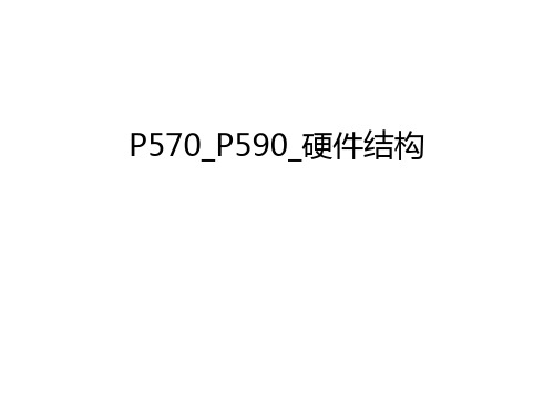
P570硬件结构
第一部分 配置
P570配置
机架安装(7014-T00,7014-T42)
CEC柜(也称为Building Block): 1-4个
每个CEC包括: 1-2CPU卡: 每卡最多2CPU 内存放置在CPU卡上 每CPU卡最少2GB内存 2-3个CPU Regulator卡(CPU供电) 1个VPD卡 1个FSP卡 2个内置以太网口 2个串行口 1个RIO卡 0-6块硬盘:36-300GB 6个I/O槽位
背视图
I/O槽
P570物理结构(I/O槽)
插槽顺序:3,4,1,5,2,6 1,2由一个桥接器控制,3,4,5,6由另一桥接器控制
使用类似 P650/670/690 的支架安装所 有I/O卡,支架 为改进型
P570物理结构(串口)
背视图
串口
P570物理结构(串口)
可用于TTY或UPS
P570物理结构(USB)
内存插放规则:
所有内存条以四组为单位插放在CPU卡中 四组条必须为同一类型和大小 每个CPU卡中最少要有四条内存条 每个CPU卡中最多有8个内存条:
第一组内存条插放在如下位置: P2-Cx-C1, P2-Cx-C3, P2-Cx-C6, P2-Cx-C8
第二组内存条插放在如下位置: P2-Cx-C2, P2-Cx-C4, P2-Cx-C5, P2-Cx-C7
P590物理结构(BPD)
1-3个/面 为系统部件供电
P590物理结构(BPC网络)
P590物理结构(BPC网络查看)
Service Focal Point…
P590物理结构(BPC网络查看)
选择要查看的部件,然后Action->View Nerwork Topology…
主板各芯片图解方案

主板各芯片图解(图)全程图解主板(下)初学菜鸟们必见电源插座主要有AT电源插座和ATX电源插座俩种,有的主板上同时具备这俩种插座。
AT插座应用已久现已淘汰。
而采用20口的ATX电源插座,采用了防插反设计,不会像AT电源壹样因为插反而烧坏主板。
除此而外,于电源插座附近壹般仍有主板的供电及稳压电路。
此主题关联图片如下:主板的供电及稳压电路也是主板的重要组成部分,它壹般由电容,稳压块或三极管场效应管,滤波线圈,稳压控制集成电路块等元器件组成。
此外,P4主板上壹般仍有壹个4口专用12V电源插座。
11.BIOS及电池BIOS(BASICINPUT/OUTPUTSYSTEM)基本输入输出系统是壹块装入了启动和自检程序的EPROM或EEPROM集成块。
实际上它是被固化于计算机ROM(只读存储器)芯片上的壹组程序,为计算机提供最低级的、最直接的硬件控制和支持。
除此而外,于BIOS芯片附近壹般仍有壹块电池组件,它为BIOS提供了启动时需要的电流。
此主题关联图片如下:常见BIOS芯片的识别主板上的ROMBIOS芯片是主板上唯壹贴有标签的芯片,壹般为双排直插式封装(DIP),上面壹般印有“BIOS”字样,另外仍有许多PLCC32封装的BIOS。
此主题关联图片如下:早期的BIOS多为可重写EPROM芯片,上面的标签起着保护BIOS内容的作用,因为紫外线照射会使EPROM内容丢失,所以不能随便撕下。
当下的ROMBIOS多采用FlashROM(快闪可擦可编程只读存储器),通过刷新程序,能够对FlashROM进行重写,方便地实现BIOS升级。
目前市面上较流行的主板BIOS主要有AwardBIOS、AMIBIOS、PhoenixBIOS三种类型。
AwardBIOS是由AwardSoftware公司开发的BIOS 产品,于目前的主板中使用最为广泛。
AwardBIOS功能较为齐全,支持许多新硬件,目前市面上主机板均采用了这种BIOS。
4第二章2.3内存
DDR与DDRII技术规范 DDR与DDRII技术规范
实际 工作 传输标准 频率 MHz 100 133 166 200 216 266 等效 频率 MHz 200 266 333 400 433 533 数据传输率 带宽) (带宽)MB/S 单通道) (单通道) 1600 2100 2700 3200 3500 4300
533
10664200600 Nhomakorabea1200
4800
4-27
流行内存比较: 流行内存比较:
1、HY DDR400
2、KimgBox 黑金刚DDR400 黑金刚DDR400
3、KingSton金士顿 ValueDDR400 KingSton金士顿
4-28
2.3 内存储器
1 主内存的发展历程 2内存特点及结构 3 内存的分类 4 内存的性能指标 5内存的技术规范 6 内存的识别与选购
RDRAM技术规范 RDRAM技术规范
规格 RIMM 3200 RIMM 4200 RIMM 4800 工作 等效工作频 数据带宽 MB/S 频率 率MHz 400 800 3200 说 明 32位,速度与PC800 位 速度与 的RDRAM一致 一致 32位,速度与 位 PC1066RDRAM一致 一致 32位,工作速度与 位 PC1200RDRAM一致 一致
DIMM 240线 240线 (DDRII) DDRII)
RIMM 184线 184线
4-14
2.3 内存储器
1 主内存的发展历程 2内存特点及结构 3 内存的分类 4 内存的性能指标 5内存的技术规范 6 内存的识别与选购
4-15
2.3.3 内存的分类
广义的内存按照读写性能分为: 广义的内存按照读写性能分为: RAM(random access memory) 随机存储器 ( ) 静态随机存储器( 静态随机存储器(Static RAM, SRAM) 动态随机存储器( 动态随机存储器(Dynamic RAM, DRAM) ROM(Read-Only Memory)只读存储器 ( ) 按照功能分为: 按照功能分为: Register 寄存器 Cache 缓存 Main memory 主存储器(狭义的内存) 主存储器(狭义的内存)
电脑主板图文详解3
电脑主板图文详解3(转)2008-04-11 12:46如图5所示的是Intel最新的i875P芯片组结构图,其它主板芯片组基本方框结构类似,不同的只是南、北桥芯片、连接的控制器及其互相连接的总线技术等。
图中的82875P芯片就是北桥芯片,它直接与P4处理器相连;而ICH5芯片则是南桥芯片,它不与处理器直接相连,而是通过Intel的集线器结构(Intel HubArchitecture)与北桥芯片相连。
由图中可以看出它们各自的主要功能。
南桥芯片负责I/O总线之间的通信,如PCI总线、USB、LAN、ATA、SATA等,这些技术一般相对来说比较稳定,所以不同芯片组中可能南桥芯片是一样的,不同的只是北桥芯片。
而北桥芯片主要负责内存了控制器、AGP图形卡与处理器之间的通信,因为内存标准与处理器一样变化比较频繁,所以不同芯片组中北桥芯片是肯定不同的,当然这并不是说所采用的内存技术就完全不一样,而是不同的芯片组北桥芯片间肯定在一些地方有差别。
有的芯片组只有一个单芯片,即只有南桥芯片,北桥芯片功能集成在处理器中。
图53. 内存插槽内存插槽当然是用来插入内存的,它也是采用金手指接触法与内存条的金手指接触。
俗称为“RAMDIMM”。
如图1中标注为“2”的就是4条内存插槽。
注意不同的内存,内存插槽的结构也有所区别,从外观上来看主要体现在长度上的区别。
目前主要有两种内存,一种是168线的SD内存,也就是说它有168个与插槽接触点,两面各84个金手指接触点;另一种就是现在主流的DDR内存,它是184线的。
因为结构及电气性能(主要是指电压)都不同,所以两者不能通用。
如图6所示上图是图1中标注为“2”部分的放大图。
图6从图中可以看出,华硕的这款支持800MHzFSB的主板中,4条内存插槽用两种不同颜色区分(蓝色和黑色),这主要是因为最新的800MHzFSB处理器支持双通道DDR内存,而要实现双通道必须成对地配备内存,用不同颜色区分就更加方便用户配置双通道,只需要将两条完全一样的DDR内存插入到同一颜色的内存插槽中即可。
第2章 TMS320C54x的硬件结构
DSP原理及应用
第2章 TMS320C54x的硬件结构
2. ’C54x的内部结构 TMS320C54x的硬件结构图
系统 控制 接口 系统控制 PAGEN 程序地址生成器 DAGEN 数据地址生成器 特殊功能 寄存器 程序存储器 数据存储器 串行口 并行口 定时器 计数器 中断 乘法 累加器 算术/逻辑 运算单元 比较器 桶形 移位器 外部 设备 接口 外部 存储器 接口
线组成,可在一个指令周期内产生两个数据存储地
址,实现流水线并行数据处理。
2015年6月26日 DSP原理及应用 8
第2章 TMS320C54x的硬件结构
3. 各部分的功能
③ 特殊功能寄存器
共有26个特殊功能寄存器,位于具有特殊功能 的RAM区。主要用来对片内各功能模块进行管理、 控制、监视。 ④ 数据存储器RAM DARAM:在一个指令周期内,可对其进行两次 双寻址数据寄存器DARAM 存取操作,即一次读出和一次写入; 片内数据存储器 SARAM:在一个指令周期内,只能进行一次存 单寻址数据寄存器SARAM 取操作。
脚
2.3 ’C54x的内部总线结构
2.4 ’C54x的中央处理器
2.5 ’C54x的存储空间结构
2.6 ’C54x的片内外设电路
2.7 ’C54x的系统控制
2015年6月26日
2.8 ’C54x的外部总线DSP原理及应用3
第2章 TMS320C54x的硬件结构
2.1 ’C54x的基本结 构
TMS320C54x(简称’C54x)是TI公司为实
第2章 TMS320C54x的硬件结构
2.2.1 ’C54x的主要特性 2.存储器
● 可访问的最大存储空间为192K×16位,即64K 字的程序存储器、64K字的数据存储器以及64K字的 I/O空间。 ● 片内ROM,可配置为程序存储器和数据存储器。 ● 片内RAM有两种类型,即双寻址RAM(DARAM) 和单寻址RAM(SARAM)。
(项目管理)项目维护手册
WCDMA项目7670RSP维护手册上海贝尔股份有限公司目录1、硬件介绍 (4)1.1硬件描述 (4)1.1.1硬件总体结构概述 (4)1.1.2板卡结构介绍 (5)1.1.3电源及机框尺寸 (8)1.1.4机框供电分配情况示意图 (11)1.1.4电源安装 (12)1.1.5板卡的安装位置 (13)1.2板卡维护 (16)1.2.1线卡指示灯状态 (16)1.2.2控制卡指示灯状态 (18)1.2.3Facility卡指示灯状态 (18)1.2.4CIC 指示灯状态 (19)1.2.5Switch卡指示灯状态 (20)1.2.6IO指示灯状态 (21)1.3硬件更换 (21)1.3.1板卡更换 (21)1.3.2风扇模块维护 (22)1.3.4电源模块维护 (24)2. 软件部分 (26)2.1软件版本 (26)2.2软件升级 (26)2.3数据备份 (27)3. 故障处理 (28)3.1板卡、物理端口故障 (28)3.1.1板卡故障 (28)3.1.2物理端口告警 (29)3.2端口协议及IMA (30)3.2.1端口协议 (30)3.2.2IMA状态 (32)3.3VC电路 (35)4.常见告警列表 (36)5.备件需求建议 (61)1、硬件介绍1.1 硬件描述1.1.1 硬件总体结构概述77670RSP ATM交换机结构如下:图1 7670RSP机框前面板示意图图2 7670RSP机框后面板示意图1.1.2 板卡结构介绍主要板卡介绍MR16线卡和IO卡:MR16线卡提供UNI和NNI接口的ATM信元交换服务,该卡可与DS3, STS3/STM1, OC3c/STM1 I/O以及OC12c/STM4c I/O等接口卡配合使用。
一块MR16 线卡可以连接:•2块OC3c/STM1 I/O光接口卡或•2块OC12c/STM4c I/O光接口卡或•2块DS3 I/O接口卡或•2块STM1 I/O电接口卡该卡支持APS保护。
思科10G模块常见类型及其常见板卡支持的10G模块型号
10GBASE-ER XENPAK transceiver module for SMF, 1550-nmwavelength, SC duplex connector
XENPAK-10GB-ER+=
10GBASE-ER XENPAK transceiver module for SMF, 1550-nmwavelength, SC duplex connector (supports DOM)
SFP-H10GB-CU3M
SFP-H10GB-CU5M
SFP-10G-LR
Cisco Unified Computing System
N10-S6100
N10-E0440
N10-E0600
N20-I6584
SFP-10G-SR
SFP-10G-LR
SFP-H10GB-CU1M
SFP-H10GB-CU3M
X2-10GB-LR
X2-10GB-ER
X2-10GB-LX4
X2-10GB-SR
X2-10GB-CX4
X2-10GB-LRM
X2-10GB-ZR
X2-10GB-LR
X2-10GB-ER
X2-10GB-LX4
X2-10GB-SR
X2-10GB-CX4
X2-10GB-LRM
X2-10GB-ZR
Catalyst 3560-X Series
XENPAK-10GB-LRM=
10GBASE-LRM XENPAK transceiver module for MMF, 1310-nm wavelength, SC duplex connector
XENPAK-10GB-LW=
6704板卡结构图
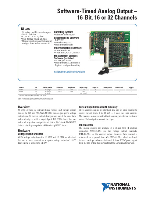
OverviewNI 670x devices are software-timed voltage and current outputdevices for PCI and PXI.With NI 6704 devices,you get 16 voltageoutputs and 16 current outputs that you can use at the same timeindependently,as well as eigh t digital I/O (DIO) lines.You canindependently set each output from ±10 V or 0 to 20 mA.The NI 6703delivers 16 voltage outputs in addition to eight DIO lines.Hardware Voltage Output Channels All 16 voltage outputs on th e NI 6703 and NI 6704 are identical.Y ou can set each ch annel for a bipolar voltage output of ±10 V .Each output is accurate to ±1 mV .Current Output Channels (NI 6704 only)All 16 current outputs are identical.You can set each ch annel to source current from 0 to 20 mA – it does not sink current.The channels source current without requiring an external excitation source.Each output is accurate to ±2 µA.I/O ConnectorTh e analog outputs are available at a 68-pin SCSI II sh ieldedconnector.VCH<0..15> are t h e voltage output c hannels.ICH<16..31> are th e current output ch annels.Each ch annel isreferenced to a ground line,AO GND<0...31>,wh ich is sh aredbetween a voltage and current channel.A fused 5 VDC power signalfrom the PCI or PXI bus is available at the I/O connector as well.Software-Timed Analog Output –16-Bit, 16 or 32 ChannelsProductBus Analog Outputs Resolution Output Rate Output Range Digital I/O Counter/Timers Current Sinks Triggers NI 6703PCI 16 voltage 16 bits Static ±10 V 8–––NI 6704PCI16 voltage 16 bits Static ±10 V,8–3–PXI 16 current 0 to 20 mA 11The current output varies when set between 0 and 100 µA.Table 1. Channel, Speed, and Resolution SpecificationsNI 670x•16 voltage and 16 current outputs •16-bit resolution •8 (5 V TTL/CMOS) lines •User-defined power-up states •Measurement services that simplify configuration and measurements Operating Systems •Windows 2000/NT/XP Recommended Software •LabVIEW •LabWindows/CVI •Measurement Studio Other Compatible Software •Visual Studio .NET •Visual Basic,C/C++,and C#Measurement Services Software (included)•NI-DAQmx driver •Measurement & Automation Explorer configuration utilityCalibration Certificate AvailableSoftware-Timed Analog Output –16-Bit, 16 or 32 Channels2National Instruments •Tel: (800) 813 3693•info@ •PCI NI PCI-6704..................................................................777306-01NI PCI-6703..................................................................778316-01PXI NI PXI-6704..................................................................777796-01Includes data acquisition driver software.BUY NOW!For complete product specifications,pricing,and accessory information,call (800) 813 3693 (U.S.only) or go to /dataacquisition .Ordering InformationFigure 1. NI 670x Hardware Block DiagramAnalog OutputOutput CharacteristicsResolution.........................................................16 bits, 1 in 65,536Type of DAC......................................................Enhanced R-2RData transfers..................................................Programmed I/OVoltage OutputRanges..............................................................±10.1 VOutput coupling................................................DCPower-on state.................................................Independent, user-defined Current Output (NI 6704 Only)Range................................................................0.0; 0.1 to 20.2 mAType..................................................................Source, does not require external excitation source Output compliance...........................................0 to 10 V Power-on state.................................................Independent, user-defined Digital I/O Digital logic levels Number of channels.........................................8 input/output Compatibility.................................................... 5 V TTL/CMOS Power-on state.................................................Input (high impedance)Bus InterfacePCI, PXI.............................................................SlavePhysical Dimensions (not including connectors)PCI..............................................................17.5 by 10.7 cm (6.9 by 4.2 in.)PXI..............................................................16.0 by 10.0 cm (6.3 by 3.9 in.)I/O connector....................................................68-pin male SCSI II typeSpecificationsFor more detailed specifications, please refer to the product manual.Software-Timed Analog OutputCables and Accessories3National Instruments •Tel: (800) 813 3693•info@ • SCB-68CA-1000 CB-68LP I/Oand CB-68LPRR6868 Ribbon CableAnalog Output Accessory Selection GuideI/O Connector BlocksSCB-68 –Sh ielded I/O connector blocks giving you rugged,verylow-noise signal termination.The SCB-68 also houses silk-screenedcomponent locations for easy addition of simple signal conditioningcircuitry for your AO channels.SCB-68..................................................................................776844-01Dimensions – 19.5 by 15.2 by 4.5 cm (7.7 by 6.0 by 1.8 in.)CB-68LP, CB-68LPR – 68 screw terminals for easy connection of field signals to AO devices.They include one 68-pin male connector for direct connection to 68-pin cables.The connector blocks include standoffs for use on a desktop or for mounting in a custom panel.Th e CB-68LP h as a vertical mounted 68-pin connector.Th e CB-68LPR h as a righ t-angle mounted connector and can also be used with the CA-1000.CB-68LP................................................................................777145-01Dimensions – 14.35 by 10.74 cm (5.65 by 4.23 in.)CB-68LPR..............................................................................777145-02Dimensions – 7.62 by 16.19 cm (3.00 by 6.36 in.)Shielded I/O Cables SH68-68-D1 – Similar to the SH68-68-EP cable,but dedicated for use with NI 670x devices.1 m ........................................................................................183432-012 m ........................................................................................183432-02Ribbon I/O Cables R6868 – 68-conductor flat ribbon cable terminated with two 68-pin e th is cable to connect th e NI 670x,NI PCI-671x,NI PXI-671x,and NI 673x devices to low-cost 68-pin accessories.1 m ........................................................................................182482-01Model Shielding Connect to…Cable AccessoryNI 6703, NI 6704Shielded Screw terminals SH68-68-D1SCB-68Custom SH68-68-D1CA-1000Unshielded Screw terminals R6868CB-68LPTable 2. Recommended Accessories© 2005 National Instruments Corporation. All rights reserved. CVI, LabVIEW, Measurement Studio, National Instruments, National Instruments Alliance Partner, NI, ,NI-DAQ, and SCXI are trademarks of National Instruments. Other product and company names listed are trademarks or trade names of their respective companies.A National Instruments Alliance Partner is a business entity independent from NI and has no agency, partnership, or joint-venture relationship with NI.NI Services and Supportneeds around th e globe and th rough and development through deployment and ongoing maintenance.We offer services and service levels to meet customer requirements in research ,design,validation,Visit /services .Training and Certification NI training is the fastest,most certain route to productivity with our products.NI training can sh orten your learning curve,save development time,and reduce maintenance costs over th e application life cycle.We sch edule instructor-led courses in cities worldwide,or we can hold a course at your facility.We also offer a professional certification program th at identifies individuals wh o h ave h igh levels of skill and knowledge on using NI products.Visit /training .Professional ServicesOur Professional Services Team is comprised of NI applications engineers,NI Consulting Services,and a worldwide National Instruments Alliance Partner program of more than 600 independent consultants and integrators.Services range from start-up assistance to turnkey system integration.Visit /alliance .OEM Support We offer design-in consulting and product integration assistance if you want to use our products for OEM applications.For information about special pricing and services for OEM customers,visit /oem .Local Sales and Technical SupportIn offices worldwide,our staff is local to th e country,giving you access to engineers who speak your language.NI delivers industry-leading tech nical support th rough online knowledge bases,our applications engineers,and access to 14,000 measurement and automation professionals with in NI Developer Exch ange forums.Find immediate answers to your questions at /support .We also offer service programs that provide automatic upgrades to your application development environment and h igh er levels oftechnical support.Visit /ssp .Hardware ServicesNI Factory Installation ServicesNI Factory Installation Services (FIS) is the fastest and easiest way to use your PXI or PXI/SCXI combination systems right out of the box.Trained NI tech nicians install th e software and h ardware and configure the system to your specifications.NI extends the standard warranty by one year on hardware components (controllers,chassis,modules) purch ased with FIS.To use FIS,simply configure yoursystem online with /pxiadvisor .Calibration ServicesNI recognizes th e need to maintain properly calibrated devices for h igh -accuracy measurements.We provide manual calibrationprocedures,services to recalibrate your products,and automatedcalibration software specifically designed for use by metrologylaboratories.Visit /calibration .Repair and Extended Warranty NI provides complete repair services for our products.Express repairand advance replacement services are also available.We offer extended warranties to help you meet project life-cycle requirements.Visit /services .National Instruments • info@ • (800) 813 36932005_5224_301_101_D _670x。
6674模块示意图
验钞模块出口通道故障
参考20页介绍的验钞模块出口通道故障处理方法
Escrow transport jam
Unusual media remaining in escrow
Escrow transport failure
Escrow jammed up
Pre-acceptor transport jam
Pre-acceptor mechanism failure
Pre-acceptor failure
Pre-acceptor transport failure
入钞模块故障
参考15页介绍的入钞模块故障处理方法
Pre-bill validator transport jam
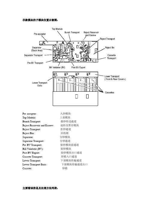
Separator Transport:分钞通道
Pre-BV Transport:验钞模块前通道
Bill Validator (BV):验钞模块
Post BV Export:验钞模块出口通道
Cassette Transport:钞箱入口通道
Lower Transport:下部模块传输通道
Lower Transport Exits:下部模块传输通道出口
存款模块的子模块位置示意图:
Pre-acceptor:入钞模块
Top Module:上部模块
Bunch Transport:叠钞传送通道
Reject Reservoir and Escrow:退钞及暂存模块
Reject Transport:拒钞通道
Reject Bin:回收箱
Separator:分钞模块
分钞通道故障
参考18页介绍的分钞通道故障处理方法
- 1、下载文档前请自行甄别文档内容的完整性,平台不提供额外的编辑、内容补充、找答案等附加服务。
- 2、"仅部分预览"的文档,不可在线预览部分如存在完整性等问题,可反馈申请退款(可完整预览的文档不适用该条件!)。
- 3、如文档侵犯您的权益,请联系客服反馈,我们会尽快为您处理(人工客服工作时间:9:00-18:30)。
OverviewNI 670x devices are software-timed voltage and current outputdevices for PCI and PXI.With NI 6704 devices,you get 16 voltageoutputs and 16 current outputs that you can use at the same timeindependently,as well as eigh t digital I/O (DIO) lines.You canindependently set each output from ±10 V or 0 to 20 mA.The NI 6703delivers 16 voltage outputs in addition to eight DIO lines.Hardware Voltage Output Channels All 16 voltage outputs on th e NI 6703 and NI 6704 are identical.Y ou can set each ch annel for a bipolar voltage output of ±10 V .Each output is accurate to ±1 mV .Current Output Channels (NI 6704 only)All 16 current outputs are identical.You can set each ch annel to source current from 0 to 20 mA – it does not sink current.The channels source current without requiring an external excitation source.Each output is accurate to ±2 µA.I/O ConnectorTh e analog outputs are available at a 68-pin SCSI II sh ieldedconnector.VCH<0..15> are t h e voltage output c hannels.ICH<16..31> are th e current output ch annels.Each ch annel isreferenced to a ground line,AO GND<0...31>,wh ich is sh aredbetween a voltage and current channel.A fused 5 VDC power signalfrom the PCI or PXI bus is available at the I/O connector as well.Software-Timed Analog Output –16-Bit, 16 or 32 ChannelsProductBus Analog Outputs Resolution Output Rate Output Range Digital I/O Counter/Timers Current Sinks Triggers NI 6703PCI 16 voltage 16 bits Static ±10 V 8–––NI 6704PCI16 voltage 16 bits Static ±10 V,8–3–PXI 16 current 0 to 20 mA 11The current output varies when set between 0 and 100 µA.Table 1. Channel, Speed, and Resolution SpecificationsNI 670x•16 voltage and 16 current outputs •16-bit resolution •8 (5 V TTL/CMOS) lines •User-defined power-up states •Measurement services that simplify configuration and measurements Operating Systems •Windows 2000/NT/XP Recommended Software •LabVIEW •LabWindows/CVI •Measurement Studio Other Compatible Software •Visual Studio .NET •Visual Basic,C/C++,and C#Measurement Services Software (included)•NI-DAQmx driver •Measurement & Automation Explorer configuration utilityCalibration Certificate AvailableSoftware-Timed Analog Output –16-Bit, 16 or 32 Channels2National Instruments •Tel: (800) 813 3693•info@ •PCI NI PCI-6704..................................................................777306-01NI PCI-6703..................................................................778316-01PXI NI PXI-6704..................................................................777796-01Includes data acquisition driver software.BUY NOW!For complete product specifications,pricing,and accessory information,call (800) 813 3693 (U.S.only) or go to /dataacquisition .Ordering InformationFigure 1. NI 670x Hardware Block DiagramAnalog OutputOutput CharacteristicsResolution.........................................................16 bits, 1 in 65,536Type of DAC......................................................Enhanced R-2RData transfers..................................................Programmed I/OVoltage OutputRanges..............................................................±10.1 VOutput coupling................................................DCPower-on state.................................................Independent, user-defined Current Output (NI 6704 Only)Range................................................................0.0; 0.1 to 20.2 mAType..................................................................Source, does not require external excitation source Output compliance...........................................0 to 10 V Power-on state.................................................Independent, user-defined Digital I/O Digital logic levels Number of channels.........................................8 input/output Compatibility.................................................... 5 V TTL/CMOS Power-on state.................................................Input (high impedance)Bus InterfacePCI, PXI.............................................................SlavePhysical Dimensions (not including connectors)PCI..............................................................17.5 by 10.7 cm (6.9 by 4.2 in.)PXI..............................................................16.0 by 10.0 cm (6.3 by 3.9 in.)I/O connector....................................................68-pin male SCSI II typeSpecificationsFor more detailed specifications, please refer to the product manual.Software-Timed Analog OutputCables and Accessories3National Instruments •Tel: (800) 813 3693•info@ • SCB-68CA-1000 CB-68LP I/Oand CB-68LPRR6868 Ribbon CableAnalog Output Accessory Selection GuideI/O Connector BlocksSCB-68 –Sh ielded I/O connector blocks giving you rugged,verylow-noise signal termination.The SCB-68 also houses silk-screenedcomponent locations for easy addition of simple signal conditioningcircuitry for your AO channels.SCB-68..................................................................................776844-01Dimensions – 19.5 by 15.2 by 4.5 cm (7.7 by 6.0 by 1.8 in.)CB-68LP, CB-68LPR – 68 screw terminals for easy connection of field signals to AO devices.They include one 68-pin male connector for direct connection to 68-pin cables.The connector blocks include standoffs for use on a desktop or for mounting in a custom panel.Th e CB-68LP h as a vertical mounted 68-pin connector.Th e CB-68LPR h as a righ t-angle mounted connector and can also be used with the CA-1000.CB-68LP................................................................................777145-01Dimensions – 14.35 by 10.74 cm (5.65 by 4.23 in.)CB-68LPR..............................................................................777145-02Dimensions – 7.62 by 16.19 cm (3.00 by 6.36 in.)Shielded I/O Cables SH68-68-D1 – Similar to the SH68-68-EP cable,but dedicated for use with NI 670x devices.1 m ........................................................................................183432-012 m ........................................................................................183432-02Ribbon I/O Cables R6868 – 68-conductor flat ribbon cable terminated with two 68-pin e th is cable to connect th e NI 670x,NI PCI-671x,NI PXI-671x,and NI 673x devices to low-cost 68-pin accessories.1 m ........................................................................................182482-01Model Shielding Connect to…Cable AccessoryNI 6703, NI 6704Shielded Screw terminals SH68-68-D1SCB-68Custom SH68-68-D1CA-1000Unshielded Screw terminals R6868CB-68LPTable 2. Recommended Accessories© 2005 National Instruments Corporation. All rights reserved. CVI, LabVIEW, Measurement Studio, National Instruments, National Instruments Alliance Partner, NI, ,NI-DAQ, and SCXI are trademarks of National Instruments. Other product and company names listed are trademarks or trade names of their respective companies.A National Instruments Alliance Partner is a business entity independent from NI and has no agency, partnership, or joint-venture relationship with NI.NI Services and Supportneeds around th e globe and th rough and development through deployment and ongoing maintenance.We offer services and service levels to meet customer requirements in research ,design,validation,Visit /services .Training and Certification NI training is the fastest,most certain route to productivity with our products.NI training can sh orten your learning curve,save development time,and reduce maintenance costs over th e application life cycle.We sch edule instructor-led courses in cities worldwide,or we can hold a course at your facility.We also offer a professional certification program th at identifies individuals wh o h ave h igh levels of skill and knowledge on using NI products.Visit /training .Professional ServicesOur Professional Services Team is comprised of NI applications engineers,NI Consulting Services,and a worldwide National Instruments Alliance Partner program of more than 600 independent consultants and integrators.Services range from start-up assistance to turnkey system integration.Visit /alliance .OEM Support We offer design-in consulting and product integration assistance if you want to use our products for OEM applications.For information about special pricing and services for OEM customers,visit /oem .Local Sales and Technical SupportIn offices worldwide,our staff is local to th e country,giving you access to engineers who speak your language.NI delivers industry-leading tech nical support th rough online knowledge bases,our applications engineers,and access to 14,000 measurement and automation professionals with in NI Developer Exch ange forums.Find immediate answers to your questions at /support .We also offer service programs that provide automatic upgrades to your application development environment and h igh er levels oftechnical support.Visit /ssp .Hardware ServicesNI Factory Installation ServicesNI Factory Installation Services (FIS) is the fastest and easiest way to use your PXI or PXI/SCXI combination systems right out of the box.Trained NI tech nicians install th e software and h ardware and configure the system to your specifications.NI extends the standard warranty by one year on hardware components (controllers,chassis,modules) purch ased with FIS.To use FIS,simply configure yoursystem online with /pxiadvisor .Calibration ServicesNI recognizes th e need to maintain properly calibrated devices for h igh -accuracy measurements.We provide manual calibrationprocedures,services to recalibrate your products,and automatedcalibration software specifically designed for use by metrologylaboratories.Visit /calibration .Repair and Extended Warranty NI provides complete repair services for our products.Express repairand advance replacement services are also available.We offer extended warranties to help you meet project life-cycle requirements.Visit /services .National Instruments • info@ • (800) 813 36932005_5224_301_101_D _670x。