双工器
双工器的原理

双工器的原理双工器是一种用于无线通信系统的重要组件,它可以实现在同一频率上同时进行收发信号,从而实现双向通信。
在无线通信领域,双工器的原理和工作原理是非常重要的,下面我们将详细介绍双工器的原理。
首先,双工器的原理基于电磁学和无线通信技术。
在无线通信中,发送和接收信号需要使用同一频率的无线电波。
然而,由于发送和接收信号是同时进行的,因此需要一种能够在同一频率上实现双向通信的设备,这就是双工器。
双工器的原理主要是通过利用电磁场的特性来实现的。
当发送信号时,双工器会将发送信号传输到天线上,并将接收信号从天线传输到接收器上。
而当接收信号时,双工器则会将接收信号传输到接收器上,并将发送信号从发送器传输到天线上。
这样,就实现了在同一频率上同时进行收发信号的功能。
双工器的原理还涉及到信号的隔离和耦合。
在双工器中,发送和接收信号需要进行隔离,以避免相互干扰。
双工器通过设计合适的结构和材料,可以实现对发送和接收信号的有效隔离,从而确保信号的质量和稳定性。
同时,双工器还需要实现对发送和接收信号的耦合,以确保信号能够顺利地传输和接收。
双工器的原理还涉及到频率选择和匹配。
在无线通信中,频率选择和匹配是非常重要的,它直接影响到信号的传输和接收质量。
双工器需要能够有效地选择和匹配频率,以确保发送和接收信号在同一频率上进行通信,并且能够在不同频率下进行隔离和耦合。
总的来说,双工器的原理是基于电磁学和无线通信技术的,它通过合理的结构设计和材料选择,实现了在同一频率上同时进行收发信号的功能。
双工器在无线通信系统中起着非常重要的作用,它的原理和工作原理对于理解和设计无线通信系统具有重要意义。
希望本文能够帮助大家更好地理解双工器的原理和工作原理。
双工器工艺流程
双工器工艺流程下载温馨提示:该文档是我店铺精心编制而成,希望大家下载以后,能够帮助大家解决实际的问题。
文档下载后可定制随意修改,请根据实际需要进行相应的调整和使用,谢谢!并且,本店铺为大家提供各种各样类型的实用资料,如教育随笔、日记赏析、句子摘抄、古诗大全、经典美文、话题作文、工作总结、词语解析、文案摘录、其他资料等等,如想了解不同资料格式和写法,敬请关注!Download tips: This document is carefully compiled by theeditor. I hope that after you download them,they can help yousolve practical problems. The document can be customized andmodified after downloading,please adjust and use it according toactual needs, thank you!In addition, our shop provides you with various types ofpractical materials,such as educational essays, diaryappreciation,sentence excerpts,ancient poems,classic articles,topic composition,work summary,word parsing,copy excerpts,other materials and so on,want to know different data formats andwriting methods,please pay attention!双工器工艺流程一、设计与规划阶段。
在开始双工器的制作之前,需要进行精心的设计与规划。
双工器attennution参数

双工器attennution参数
双工器(duplexer)是一种用于无线通信系统的设备,用于允
许发送和接收在同一频率上进行。
双工器的attenuation参数是指
在双工器中,从一个端口到另一个端口的信号衰减量。
这个参数通
常以分贝(dB)为单位来衡量。
双工器的attenuation参数对于无线通信系统的性能至关重要。
在双工器中,由于发送和接收信号在同一频率上进行,因此必须确
保发送信号不会对接收信号产生干扰。
attenuation参数越高,表
示从一个端口到另一个端口的信号衰减越大,这意味着发送信号对
接收信号的干扰越小,系统的性能也越好。
attenuation参数的大小取决于双工器的设计和制造质量,以
及工作频率等因素。
通常情况下,双工器的attenuation参数越小
越好,因为这意味着更少的信号衰减,发送和接收之间的干扰也会
更小。
在实际应用中,工程师需要根据具体的通信系统要求和环境
条件来选择合适的双工器,以确保系统的性能和稳定性。
总之,双工器的attenuation参数是衡量从一个端口到另一个
端口的信号衰减量的重要参数,对于无线通信系统的性能至关重要。
工程师需要根据实际需求选择合适的双工器,以确保系统的正常运行和性能优越。
双工器 合路器

双工器合路器1. 什么是双工器和合路器?双工器(Duplexer)和合路器(Combiner)是无线通信系统中常用的两种设备。
它们在无线通信系统的设计和运行中起着重要的作用。
1.1 双工器双工器是一种用于实现双工通信的设备。
双工通信是指在同一频段上同时进行发送和接收信号的通信方式。
在无线通信系统中,双工器可以实现将发送和接收信号分离,使得发送和接收信号可以在同一频段上同时进行,提高了频谱利用率。
双工器通常由一对滤波器和耦合器组成。
滤波器用于将发送和接收信号分离,并且具有高隔离度,以防止发送信号对接收信号的干扰。
耦合器用于将发送和接收信号分别耦合到天线和收发器中。
1.2 合路器合路器是一种用于将多个信号合并成一个信号的设备。
在无线通信系统中,合路器可以将多个发送信号合并成一个发送信号,实现多用户同时发送信号的功能。
合路器通常由一对耦合器和一个合路器组成。
耦合器用于将多个发送信号耦合到合路器中,而合路器则将多个发送信号合并成一个发送信号。
合路器还具有高隔离度,以防止不同发送信号之间的干扰。
2. 双工器和合路器的应用双工器和合路器在无线通信系统中有广泛的应用,特别是在移动通信系统中。
2.1 移动通信系统在移动通信系统中,双工器和合路器被广泛应用于基站和移动终端之间的通信。
基站需要同时发送和接收信号,而移动终端也需要同时发送和接收信号,双工器可以实现双方在同一频段上同时进行通信。
双工器在移动通信系统中的应用不仅提高了频谱利用率,还提高了通信质量。
通过使用双工器,发送信号和接收信号可以在同一频段上同时进行,避免了频段切换带来的延迟和干扰。
2.2 无线电通信双工器和合路器也被广泛应用于无线电通信系统中。
无线电通信系统中的设备通常需要同时发送和接收信号,双工器可以实现设备在同一频段上同时进行发送和接收。
双工器在无线电通信系统中的应用使得设备可以在相同的频段上进行通信,提高了频谱利用率。
同时,双工器还可以提供高隔离度,减少发送信号对接收信号的干扰。
双工器

双工器广泛应用于通信、电子战领域中,它使具有一定间隔的两个频段获得较大的隔离,按用途可大致分为三种:收-发双工器、收-收双工器、发-发双工器。
收-发双工器用于防止发射大信号直接进入接收机前端引起接收信道饱和甚至烧毁,同时避免发射机噪声对接收灵敏度的影响;收-收双工器用于两台不同频的接收机共用一付天线,避免直接使用分路器所带来的整机噪声系数增大,同时具有信号预选功能;发-发双工器用于两台不同频的发射机共用一付天线,避免使用合路器所带来功率损失,并防止大功率发射机相互影响,同时还能抑制输出信号谐杂波。
双工器两部调频发射机用不同的工作频率同时广播不同的节目内容,如果每一台调频发射机都相应配备一副发射天线,不但投资会大幅度地上升,同时也会给支持发射天线的铁塔的设计和架设带来极大的困难。
采用双工器的办法,可以解决两台不同工作频率的调频发射机共用一副发射天线的问题。
因为调频发射的频带宽度较电视发射机而言要窄得多,而调频发射天线又都沿用了电视发射天线的结构形式,天线的带宽可以覆盖87~108MHz调频广播的整个波段。
因此,不同工作频率的调幅发射机可以共用一副发射天线,共馈共塔减少了投资,提高了经济效益,是目前广播电台发展的方向。
5双工器的技术参数频率范围:可工作在87~108MHz整个调频广播波段内。
输入阻抗:50Ω(同轴),与调频发射机的阻抗相匹配。
输出阻抗:50Ω(同轴),与天馈线的输入阻抗相匹配。
最小频率间隔:在保证性能指标的前提下,允许双工器两个输入频率之间的最小间隔在1 2MHz左右。
输入端电压驻波比:应小于1∶1。
隔离度:它是指双工器对两个不同频率信号之间的隔离能力,如果隔离能力低(即隔离度差),就会使两个信号之间产生互调,从而降低调频广播质量。
一般要求隔离度优于26dB。
插入损耗:它是指信号经过双工器以后引起的衰减,一般要求小于0 4dB。
功率容量:双工器的功率容量要根据调频发射机的功率来确定。
双工器的工作原理

双工器的工作原理双工器是一种通信设备,它能够在同一条通信线路上同时实现双向通信,即同时进行发送和接收数据。
双工器常用于无线通信系统、计算机网络、电信传输等各个领域。
它的主要工作原理包括频分双工和时分双工两种。
频分双工(Frequency Division Duplex,FDD)是指通过将发送和接收数据的频段互相分隔开来实现双向通信。
在频分双工中,发送和接收数据的信号在频域上是互不重叠的,即分别分配给发送和接收方不同的频段。
这样,发送方只会发射特定的频率信号,而接收方只会接收其他频率信号。
例如,使用频分双工的手机通信系统中,手机A会使用一片频段进行通信,而手机B则是使用另一片频段进行通信。
因此,手机A可以同时发送和接收数据,而手机B也可以同时发送和接收数据,实现双向通信。
时分双工(Time Division Duplex,TDD)是指通过时间上的分割来实现双向通信。
在时分双工中,发送和接收数据的时间片段交替进行。
发送方在某个时间段内发送数据,然后接收方在之后的时间段内接收数据。
这种方式要求双工器能够精确地按照时间划分发送和接收数据的时间段,并能够在不同的时间段切换发送和接收的功能。
例如,在无线网络中,TDD方式被广泛应用于Wi-Fi通信。
发送方和接收方通过预定好的时间片段来交替发送和接收数据,从而实现双向通信。
无论是频分双工还是时分双工,双工器的设计都要解决两个主要问题:信号的隔离和信号的调度。
信号的隔离是指在双工器中,要保证发送和接收的信号互不干扰。
在频分双工中,发送和接收信号的频率范围不同,可以通过滤波器等方式来实现信号的分隔。
在时分双工中,发送和接收信号的时间段不同,可以通过开关等方式来控制信号的切换。
信号的调度是指在双工器中需要控制发送和接收数据的时机。
在频分双工中,需要确保发送方和接收方在同一时间内只进行发送或接收操作。
这可以通过时间同步来实现,即发送方和接收方根据预定好的时钟信号来同步工作。
双工器的工作原理

双工器的工作原理一、引言双工器是一种电子设备,可以实现在同一信道上同时传输和接收信号。
它广泛应用于通信领域,如无线电通讯、卫星通讯、光纤通讯等。
本文将介绍双工器的工作原理。
二、双工器的定义双工器是一种能够同时进行发送和接收的设备,它可以将一个信道分成两个方向,使得两个方向的信号可以同时传输而不互相干扰。
三、双工器的分类根据不同的应用场景和技术特点,双工器可以分为以下几类:1. 无线电双工器:主要用于无线电通讯中,将天线与收发机连接在一起。
2. 光纤双工器:主要用于光纤通讯中,将光纤与发射机和接收机连接在一起。
3. 卫星双工器:主要用于卫星通讯中,将地面站与卫星连接在一起。
四、双工器的原理1. 无线电双工器原理:无线电双工器主要由三部分组成:天线、滤波器和耦合装置。
当发射机发出信号时,信号通过耦合装置进入天线并发射出去;当信号到达天线时,它通过耦合装置进入滤波器,滤波器会将接收机所需要的信号通过,而将发射机的信号阻挡掉,从而实现发送和接收的分离。
2. 光纤双工器原理:光纤双工器主要由两部分组成:耦合器和光学滤波器。
当发射机发出光信号时,信号通过耦合器进入光纤并传输出去;当信号到达双工器时,它通过耦合器进入光学滤波器,滤波器会将接收机所需要的信号通过,而将发射机的信号阻挡掉。
这样就实现了发送和接收的分离。
3. 卫星双工器原理:卫星双工器主要由两部分组成:上行通道和下行通道。
上行通道是地面站向卫星发送数据的通道,下行通道是卫星向地面站发送数据的通道。
在卫星上,上行与下行之间采用频率隔离技术实现分离。
五、双工器的应用1. 无线电双工器应用:无线电双工器广泛应用于无线电通讯中,在手机、对讲机、车载电台等设备中都有应用。
2. 光纤双工器应用:光纤双工器广泛应用于光纤通讯中,如光纤局端、广域网、数据中心等。
3. 卫星双工器应用:卫星双工器广泛应用于卫星通讯中,如卫星电话、卫星电视等。
六、总结双工器是一种能够实现在同一信道上同时传输和接收信号的设备,它可以将一个信道分成两个方向,使得两个方向的信号可以同时传输而不互相干扰。
双工器定义和工作原理
什么是双工器什么是双工器双工器是异频双工电台,中继台的主要配件,其作用是将发射和接收讯号相隔离,保证接收和发射都能同时正常工作.它是由两组不同频率的阻带滤波器组成,避免本机发射信号传输到接收机。
一般双工器由六个阻带滤波器(陷波器)组成,各谐振于发射和接收频率。
接收端滤波器谐振于发射频率,并防指发射功率串入接收机,发射端滤波器谐振于接收频率。
有些双工器不标发射和接收端而只标LOW和H IGH ,如某双工器L OW=450, HIGH=460, 表示LOW端可联接450兆接收机HIGH端联接460兆发射机,也可将LOW端联接450兆发射机,HIGH端联接460兆接收机,收发频率可颠倒使用,但是不能将发射频率460的机器接置双工器450兆一端以免损坏电台和双工器。
双工器选用:应根据电台发射接收频率定制双工器。
400兆收发频率差10MHZ双工器的工作带宽在+-250kHZ可保证隔离度90db左右,单频点工作隔离度可达120db..当使用频率超过双工器额定带宽时,收发隔离度将急剧下降发射驻波增大,接收电路因受发射部分影响灵敏度下降不能正常工作。
业余无线中转台U段一般收发差5兆HZ 使用的双工器采用窄带设计,可保证隔离度不下降但工作带宽变窄为+-100KHZ. 实践证明使用双工器比用两颗天线收发效果要好。
双工器的原理双工器的结构双工器,又称天线共用器,是一个比较特殊的双向三端滤波器。
双工器既要将微弱的接受信号藕合进来,又要将较大的发射功率馈送到天线上去,且要求两者各自完成其功能而不相互影响一般的双工器由螺旋振腔体构成,由于其工作频率高,分布参数影响较大 常做成一个密封套体,各信号馈线均用屏蔽效果较好的同轴电缆 腔体形材也要求一定的光洁度,为利于散热,外观常为黑色,三个信号端一般采用标准高频接插件Q9或L16型高频插座无线通讯对双工器的要求双工器用于移动通信和在野外作为无人值守的中转台工作,其本身就决定了它的使用环境和工作条件。
双工器工作原理

双工器工作原理
双工器是一种用于同时实现双向数据传输的设备。
它基于两条信号线(线路或通道),使得两个设备可以在相同的时间段内进行双向通信。
双工器的工作原理基于时间分割和信号调制。
当一个设备发送数据时,双工器会将发送数据的信号解调并分割成两个独立的信号,一个用于发送到接收设备,另一个用于发送到发送设备。
这个过程是通过时间分割实现的,即在每个时间片段内,只有一个设备可以发送或接收数据。
在每个时间片段内,发送设备将其数据信号调制成特定的频率或编码,以便接收设备能够正确解调并恢复数据。
同样地,接收设备也会对接收到的数据信号进行解调和解码,以获取发送设备所发送的数据。
双工器使用时序和信号解调技术保证了双向数据传输的同时性。
通过精确的时序控制,发送和接收设备可以在非重叠的时间段内进行通信,确保数据的发送和接收不会发生冲突。
总之,双工器通过时间分割和信号调制的方式,实现了双向数据传输。
它能够将来自不同设备的数据进行分割和组合,使双向通信成为可能。
这种工作原理为各种通信系统和设备提供了有效的双向数据传输解决方案。
双工器的介绍
1功分器1)功分器的作用:是将功率信号平均地分成几份,给不同的覆盖区使用。
2)种类:功分器一般有二功分、三功分和四功分3种。
功分器从结构上分一般分为:微带和腔体2种。
腔体功分器内部是一条直径由粗到细程多个阶梯递减的铜杆构成,从而实现阻抗的变换,二微带的则是几条微带线和几个电阻组成,从而实现阻抗变换.主要指标:包括分配损耗、插入损耗、隔离度、输入输出驻波比、功率容限、频率范围和带内平坦度。
以下对各项指标进行说明:l 分配损耗:指的是信号功率经过理想功率分配后和原输入信号相比所减小的量。
此值是理论值,比如二功分3dB,三功分是4.8dB,四功分是6dB。
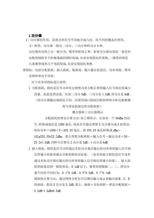
(因功分器输出端阻抗不同,应使用端口阻抗匹配的网络分析仪能够测得与理论值接近的分配损耗)耦合器和三功分器图示分配损耗的理论计算方法:如上图所示。
比如有一个30dBm的信号,转换成毫瓦是1000毫瓦,将此信号通过理想3功分器分成3份的话,每份功率=1000÷3=333.33毫瓦,将333.33毫瓦转换成dBm=10lg333.33=25.2dBm, 那么理想分配损耗=输入信号-输出功率=30-25.2=4.8dB,同样可以算出2功分是3dB,4功分是6dBl 插入损耗:指的是信号功率通过实际功分器后输出的功率和原输入信号相比所减小的量再减去分配损耗的实际值,(也有的地方指的是信号功率通过实际功分器后输出的功率和原输入信号相比所减小的量)。
插入损耗的取值范围一般腔体是:0.1dB以下;微带的则根据二、三、四功分器不同而不同约为:0.4~0.2dB、0.5~0.3dB、0.7~0.4dB。
插损的计算方法:通过网络分析仪可以测出输入端A到输出端B、C、D的损耗,假设3功分是5.3dB,那么,插损=实际损耗-理论分配损耗=5.3dB-4.8dB=0.5dB.微带功分器的插损略大于腔体功分器,一般为0.5dB左右,腔体的一般为0.1dB左右。
由于插损不能使用网络分析仪直接测出,所以一般都以整个路径上的损耗来表示(即分配损耗+插损):3.5dB/5.5dB/6.5dB等来表示二/三/四功分器的插损。
双工器原理

双工器原理双工器是一种用于无线通信系统中的重要器件,它可以实现在同一频段上同时进行发送和接收信号的功能。
在无线通信系统中,双工器的应用十分广泛,它可以用于手机、基站、卫星通信等各种场景。
那么,双工器是如何实现同时进行发送和接收的呢?接下来,我们将深入探讨双工器的原理。
首先,我们需要了解双工器的基本结构。
双工器通常由耦合器、隔离器、滤波器等组成。
其中,耦合器用于将发送和接收的信号进行耦合,隔离器用于隔离发送和接收的信号,而滤波器则用于滤除不需要的频率成分。
这些组件共同构成了双工器的基本结构,为其实现双工功能提供了基础。
其次,双工器的原理是如何实现的呢?在发送和接收信号的过程中,双工器通过合理设计耦合器、隔离器和滤波器,使得发送和接收的信号能够在同一频段上进行传输,而不会相互干扰。
具体来说,当发送信号进入双工器时,耦合器将一部分信号耦合到接收通路,而隔离器则将发送信号和接收信号进行有效隔离,使它们不会相互干扰。
同时,滤波器也起到了关键作用,它通过滤除不需要的频率成分,使得发送和接收的信号能够在同一频段上进行传输,而不会相互干扰。
双工器的原理实际上是利用了信号的频率特性和空间特性,通过合理设计器件结构和参数,使得发送和接收的信号能够在同一频段上进行传输,从而实现了双工的功能。
这种原理的实现为无线通信系统的高效运行提供了重要支持,使得无线通信系统能够更加灵活、高效地进行数据传输。
总的来说,双工器的原理是通过合理设计耦合器、隔离器和滤波器,使得发送和接收的信号能够在同一频段上进行传输,而不会相互干扰,从而实现了双工的功能。
双工器在无线通信系统中扮演着重要角色,它的原理实现为无线通信系统的高效运行提供了重要支持,为人们的日常通信生活带来了便利。
希望通过本文的介绍,能够让大家对双工器的原理有更加深入的了解。
双工器工作原理

双工器工作原理双工器是一种用于无线通信系统中的重要设备,它能够实现在同一频率上同时进行发送和接收数据的功能。
在无线通信领域,双工器扮演着至关重要的角色,它的工作原理对于整个通信系统的性能和稳定性都有着重要的影响。
下面我们将详细介绍双工器的工作原理。
首先,双工器的主要作用是实现信号的分离。
在无线通信系统中,发送和接收数据都需要使用同一频率的信号进行传输,这就需要双工器能够有效地将发送和接收的信号进行分离,避免它们之间的干扰。
双工器通过精密的设计和调节,能够在同一频率上实现信号的分离,确保发送和接收的数据能够正常进行,不会相互干扰。
其次,双工器的工作原理涉及到信号的反射和传输。
在双工器中,发送和接收的信号会经过不同的路径,其中一部分信号会被反射回来,另一部分信号则会被传输到目标设备。
双工器通过精密的设计和优化,能够确保反射和传输的信号之间不会发生干扰,从而实现信号的有效分离和处理。
另外,双工器的工作原理还涉及到滤波和衰减。
在无线通信系统中,发送和接收的信号往往会存在一定的频率偏移和干扰,这就需要双工器能够通过滤波和衰减的方式,将不需要的信号进行有效地屏蔽和处理,确保系统能够正常工作。
双工器通过内置的滤波器和衰减器,能够对信号进行精确的处理,确保系统能够在复杂的环境中稳定运行。
最后,双工器的工作原理还涉及到相位和频率的调节。
在无线通信系统中,发送和接收的信号往往需要经过精确的相位和频率调节,以确保它们能够在同一频率上进行有效的传输。
双工器通过精密的设计和调节,能够实现对信号相位和频率的精确控制,确保系统能够实现高效的通信。
总的来说,双工器的工作原理涉及到信号的分离、反射和传输、滤波和衰减、相位和频率的调节等多个方面,它通过精密的设计和优化,能够确保无线通信系统能够稳定、高效地工作。
对于理解和掌握双工器的工作原理,对于提高无线通信系统的性能和稳定性都具有重要的意义。
双工器芯片参考电路

双工器芯片参考电路
双工器芯片是用于实现全双工通信的关键组件,它可以同时进
行发送和接收数据的操作。
双工器芯片的参考电路设计是非常重要的,因为它直接影响到通信系统的性能和稳定性。
首先,双工器芯片的参考电路需要考虑到信号的传输和接收。
在设计时需要确保发送和接收的信号在同一时间不会相互干扰,可
以通过合适的滤波器和隔离器来实现。
此外,参考电路还需要考虑
到信号的放大和衰减,以确保信号质量的稳定性。
其次,参考电路还需要考虑到电源管理和地线设计。
稳定的电
源可以确保双工器芯片正常工作,而合理的地线设计可以减小信号
的干扰和噪音。
因此,参考电路的设计需要综合考虑电源管理和地
线布局。
此外,双工器芯片的参考电路还需要考虑到保护电路的设计。
在通信系统中,可能会遇到各种各样的电磁干扰和静电放电等问题,因此参考电路需要设计相应的保护电路,以确保双工器芯片不会受
到损坏。
最后,参考电路的设计还需要考虑到成本和封装。
合理的参考
电路设计不仅可以提高系统的性能,还可以降低系统的成本。
同时,封装的设计也需要考虑到双工器芯片的散热和机械强度等问题。
综上所述,双工器芯片的参考电路设计需要考虑到信号传输和
接收、电源管理和地线设计、保护电路设计以及成本和封装等多个
方面,只有综合考虑这些因素,才能设计出稳定可靠的参考电路。
双工器的原理
双工器的原理双工器是一种用于无线通信系统中的重要设备,它可以实现在同一频率上实现双向通信。
在无线通信系统中,由于频谱资源的有限性,同一频率上的双向通信一直是一个技术难题。
而双工器的出现,很好地解决了这个问题。
双工器的原理主要基于信号的频率选择性。
在通信系统中,发送和接收信号的频率是不同的,这就为双工器的设计提供了基础。
双工器通过利用信号的频率选择性,可以实现在同一频率上同时进行发送和接收。
接下来,我们将详细介绍双工器的原理。
首先,双工器利用了信号的频率选择性。
在通信系统中,发送和接收信号的频率是不同的,这就意味着可以通过选择不同的频率来实现发送和接收的分离。
双工器利用这一原理,通过特定的设计和调节,可以实现在同一频率上实现发送和接收。
其次,双工器采用了滤波器和耦合器的设计。
滤波器可以实现对不同频率信号的分离,将发送和接收信号分离开来,从而实现双向通信。
而耦合器则可以实现发送和接收信号的耦合和解耦,使得信号可以在同一频率上进行发送和接收。
另外,双工器还采用了相位补偿和功率补偿的技术。
由于发送和接收信号在同一频率上进行,会产生信号干扰和损耗的问题。
因此,双工器采用了相位补偿和功率补偿的技术,可以有效地补偿信号的相位和功率,从而保证信号的质量和稳定性。
最后,双工器的原理还涉及到了材料和结构的选择。
双工器需要采用特定的材料和结构设计,以实现对信号的精确控制和处理。
材料的选择和结构的设计对双工器的性能和稳定性有着重要的影响。
总之,双工器的原理主要基于信号的频率选择性,通过滤波器和耦合器的设计,相位补偿和功率补偿的技术,以及材料和结构的选择,可以实现在同一频率上实现双向通信。
双工器的出现,为无线通信系统的发展提供了重要的技术支持,也为人们的日常生活带来了便利。
双工器的工作原理

双工器的工作原理一、什么是双工器?双工器(Duplexer)是一种用于通信系统中的设备,它可以实现双向通信,即同时进行收发信号的操作。
在无线通信领域,双工器被广泛应用于无线电技术以及雷达系统等领域。
二、双工器的分类根据双工器的工作原理和结构,可以将其分为以下几种类型:1. 全反射式双工器全反射式双工器使用材料的反射作用来实现分离收发信号的操作。
当信号从天线传入双工器时,会被反射至相应的输出端口,而反射回来的信号则会被传入相应的接收器。
这种双工器的特点是结构简单、容量小,适用于低功率及频率较低的应用。
2. 高低通滤波器式双工器高低通滤波器式双工器使用高低通滤波器来分离收发信号。
在这种双工器中,收发信号被分别传入不同的滤波器进行频率划分,然后再通过相应的输出端口进行传输。
这种双工器适用于大功率及频率较高的应用。
3. 方向耦合式双工器方向耦合式双工器使用耦合元件来实现信号的分离。
它通过在输入和输出端口之间插入耦合元件,将收发信号耦合到相应的传输线上。
这种双工器具有较小的尺寸和较高的隔离度,适用于频段较宽的应用。
4. 动态切换式双工器动态切换式双工器可以根据信号频率进行动态切换,实现收发信号的分离。
它通过监测输入信号的频率,然后根据设定的切换规则,动态地将信号分配到相应的输出端口。
这种双工器适用于频率变化较大的应用。
三、双工器的工作原理双工器的工作原理可以简单描述为:将输入信号分离为收发两路信号,并通过相应的输出端口进行传输。
具体来说,双工器通过以下几个主要的工作步骤实现收发信号的分离:1. 信号分离收发信号从天线进入双工器后,首先需要经过信号分离的步骤。
根据双工器的类型,可以采用不同的方法进行信号分离,如反射、滤波、耦合等。
2. 信号处理分离后的收发信号需要进行进一步的处理,以便满足系统的需求。
这可能包括频率转换、幅度调整、相位校正等操作,以保证信号在传输过程中的质量和稳定性。
3. 信号传输处理后的信号通过相应的输出端口进行传输。
双工器

选用
应根据电台发射接收频率定制双工器。400兆收发频率差10MHz双工器的工作带宽在正负250kHz可保证隔离度 90db左右,单频点工作隔离度可达120db。当使用频率超过双工器额定带宽时,收发隔离度将急剧下降发射驻波 增大,接收电路因受发射部分影响灵敏度下降不能正常工作。业余无线中转台U段一般收发差5兆Hz,使用的双工 器采用窄带设计,可保证隔离度不下降但工作带宽变窄,为正负100KHz。实践证明使用双工器比用两颗天线收发 效果要好。
简介
一般双工器 由六个带阻滤波器(陷波器)组成,各谐振于发射和接收频率。接收端滤波器谐振于发射频率, 并防止发射功率串入接收机,发射端滤波器谐振于接收频率。有些双工器不标发射和接收端而只标LOW和HIGH, 如某双工器LOW=450, HIGH=460,表示LOW端可联接450兆接收机HIGH端联接460兆发射机,也可将LOW端联接 450兆发射机,HIGH端联接460兆接收机,收发频率可颠倒使用,但是不能将发射频率460的机器接置双工器450兆 一端以免损坏电台和双工器。
隔离度
双工器的隔离度 是指两个等效带阻滤波器的阻带衰减量,除一些特定的场合外,一般双工器的接收通道和 发射通道中的阻带的衰减量,也即双工器的接收端和发射端至天线端的隔离度相当的。这一点使得双工器的生产 厂家在生产管理上较为方便。因为我们所说的接收端和发射端,无非是工作频率高和低的区别,如双工器的工作 频率不合适,甚至是在10MHz的另一端,则只需调整和改接一下即可,而不会影响使用效果。
结构
双工器,是一个比较特殊的双向三端滤波器。双工器既要将微弱的接受信号耦合进来,又要将较大的发射功 率馈送到天线上去,且要求两者各自完成其功能而不相互影响。一般的双工器由螺旋振腔体构成,由于其工作频 率高,分布参数影响较大常做成一个密封套体,各信号馈线均用屏蔽效果较好的同轴电缆腔体形材也要求一定的 光洁度,为利于散热,外观常为黑色,三个信号端一般采用标准高频接插件Q9或L16型高频插座无线通讯对双工 器的要求。
双工器内部构造

双工器内部构造双工器是一种用于实现双向通信的设备,其内部构造包括多个关键组件和电路。
本文将以双工器内部构造为标题,对其进行详细介绍。
一、收发器模块双工器内部的关键组件之一是收发器模块。
该模块负责接收和发送信号,实现双向通信。
收发器模块包括发送器和接收器两部分。
发送器负责将待发送的信号转换为电磁波,并通过天线发送出去。
接收器则负责接收来自外部的信号,并将其转换为电信号供后续处理。
二、滤波器滤波器是双工器内部的另一个重要组件。
它的作用是滤除发送器发送的信号中的杂散频率,保留目标频率的信号。
滤波器可以通过不同的设计来实现不同的滤波效果,常见的有低通滤波器和带通滤波器。
三、调制解调器调制解调器是双工器内部的核心部件之一。
它负责将数字信号转换为模拟信号进行发送,并在接收端将模拟信号转换为数字信号进行处理。
调制解调器可以根据不同的调制方式来实现信号的传输,常见的调制方式有频移键控调制(FSK)和相位移键控调制(PSK)等。
四、控制电路双工器内部还包括一个控制电路,用于控制整个双工器的工作状态和参数设置。
控制电路可以通过微处理器或其他逻辑电路实现,它可以接收外部的控制信号,并根据信号的内容来控制双工器的工作模式、频率等参数。
五、功率放大器功率放大器是双工器内部的另一个重要部件。
它负责放大发送器发送的信号,以增加信号的传输距离和穿透能力。
功率放大器的设计需要考虑功率放大的效果和功率损耗的控制,以确保信号的质量和稳定性。
六、射频开关射频开关是双工器内部的关键组件之一。
它的作用是在发送和接收模式之间进行切换,以确保信号的正常传输。
射频开关可以根据控制电路的信号来进行切换操作,并保证切换的速度和精度。
七、天线天线是双工器内部的最后一个组件,它负责将发送器发送的信号转换为电磁波,并将接收到的电磁波转换为电信号供接收器处理。
天线的设计需要考虑信号的传输效果和天线的尺寸、形状等因素,以确保信号的传输质量和覆盖范围。
总结:双工器是一种用于实现双向通信的设备,其内部构造包括收发器模块、滤波器、调制解调器、控制电路、功率放大器、射频开关和天线等多个关键组件。
双工器作用——精选推荐

双工器作用浅谈双工器在双工电台中是一个十分重要的高频器件它是电台收发信号同时出入的必经途径它的好坏直接影响电台的性能指标。
下面谈谈其作用及主要性能指标。
一、双工器的结构一般的双工器由螺旋振腔体滤波器的串联谐振构成由于其工作频率高分布参数影响较大常做成一个密封套体各信号馈线均用屏蔽效果较好的同轴电缆腔体形材也要求一定的光洁度为利于散热外观常为黑色三个信号端一般采用标准高频接插件或型高频插座。
二、双工器的作用双工器是双工电台收发信号同时出入的必经途径它既能将微弱的接受信号藕合进来又能将较大的发射功率馈送到天线上去且两者各自完成其功能而不相互影响。
在双工电台中起到收发共用天线的作用。
三、双工器的主要性能指标1、工作频率双工器的工作频率范围应当不窄于电台本身的工作频率范围。
2、工作带宽是指电台配上双工器后接收机的输入带宽和发射机的输出带宽。
3、收发间隔根据我国及国际上各国无线电频率管理部门的规定用作双频双工组网的双工电台VHF的收发频差为.、UHF为。
4、特性阻抗无线对讲机的天线输入阻抗和发射机的输出阻抗均为Ω因而要求双工器的阻抗也应为Ω。
5、功率容量最大输入功率是一个双工器所能承受的最大的输入功率是双工器的一个使用安全性指标无线对讲双工电台双工器的功率容量一般为50W。
6、电压驻波比为保证整机的安全性和通信效果通常双工器的驻波比在5以下。
7、隔离度双工器的隔离度是指两个等效带阻滤波器的阻带衰减量除一些特定的场合外一般双工器的接收通道和发射通道中的阻带的衰减量也即双工器的接收端和发射端至天线端的隔离度相当的。
这一点使得双工器的生产厂家在生产管理上较为方便。
因为我们所说的接收端和发射端无非是工作频率高和低的区别如双工器的工作频率不合适甚至是在的另一端则只需调整和改接一下即可而不会影响使用效果。
通常发射端的衰减量的考虑是使得在强接收信号的情形下接收频率信号对发射机不产生互调干扰一般隔离度在75B以上时隔离度指标越大越好。
(完整版)双工器定义和工作原理(精)
什么是双工器???什么是双工器???双工器是异频双工电台,中继台的主要配件,其作用是将发射和接收讯号相隔离,保证接收和发射都能同时正常工作.它是由两组不同频率的阻带滤波器组成,避免本机发射信号传输到接收机。
一般双工器由六个阻带滤波器(陷波器)组成,各谐振于发射和接收频率。
接收端滤波器谐振于发射频率,并防指发射功率串入接收机,发射端滤波器谐振于接收频率。
有些双工器不标发射和接收端而只标LOW和HIGH ,如某双工器LOW=450, HIGH=460, 表示LOW端可联接450兆接收机HIGH端联接460兆发射机,也可将LOW端联接450兆发射机,HIGH端联接460兆接收机,收发频率可颠倒使用,但是不能将发射频率460的机器接置双工器450兆一端以免损坏电台和双工器。
双工器选用:应根据电台发射接收频率定制双工器。
400兆收发频率差10MHZ双工器的工作带宽在+-250kHZ可保证隔离度90db左右,单频点工作隔离度可达120db..当使用频率超过双工器额定带宽时,收发隔离度将急剧下降发射驻波增大,接收电路因受发射部分影响灵敏度下降不能正常工作。
业余无线中转台U段一般收发差5兆HZ 使用的双工器采用窄带设计,可保证隔离度不下降但工作带宽变窄为+-100KHZ. 实践证明使用双工器比用两颗天线收发效果要好。
双工器的原理双工器的结构双工器,又称天线共用器,是一个比较特殊的双向三端滤波器。
双工器既要将微弱的接受信号藕合进来,又要将较大的发射功率馈送到天线上去,且要求两者各自完成其功能而不相互影响一般的双工器由螺旋振腔体构成,由于其工作频率高,分布参数影响较大常做成一个密封套体,各信号馈线均用屏蔽效果较好的同轴电缆腔体形材也要求一定的光洁度,为利于散热,外观常为黑色,三个信号端一般采用标准高频接插件Q9或L16型高频插座无线通讯对双工器的要求双工器用于移动通信和在野外作为无人值守的中转台工作,其本身就决定了它的使用环境和工作条件。
- 1、下载文档前请自行甄别文档内容的完整性,平台不提供额外的编辑、内容补充、找答案等附加服务。
- 2、"仅部分预览"的文档,不可在线预览部分如存在完整性等问题,可反馈申请退款(可完整预览的文档不适用该条件!)。
- 3、如文档侵犯您的权益,请联系客服反馈,我们会尽快为您处理(人工客服工作时间:9:00-18:30)。
Z10 is the frequency dependent characteristic impedance.
Realization of a waveguide filter
3. Optimize the filter response by “interpolating existing solutions.”
What is the Transfinite Element Method?
The Finite Element method is used to solve Maxwell’s equations in the volume of arbitrary three-dimensional structures.
1. Define parameterized model by generating a grid of coarsely spaced solutions in the parameter space.
Realization of a Waveguide Filter
2. Create the entire filter from individual components.
The basic approach
1. 2. 3. 4.
5.
Select the building blocks (parametric models) for the desired structure. Verify the technique on a simple, easily verifiable model. Define the parameter space: what range of values should the parameters cover? Synthesize and optimize the desired three-dimensional structure using parametric models generated from HFSS. Verify the design using the full-wave solution of the entire structure.
Generalized s-parameters fully characterize the “black-box” behavior of a three-dimensional structure. Structures that have identical port solutions, but different internal geometries may often be analyzed separately and joined at the ports. The use of generalized s-parameters that were determined using the transfinite element method insures that the fields are matched at the port boundary. Let’s look at some examples…
Example 2: dielectric/coaxial resonator cavity filter
Waveguide components are generally simple because the behavior is accurately described by single mode interaction between components. How do we approach structures that are not easily described by single mode behavior?
βn αn
propagation constant attenuation
ˆ E ( x, y )e −γz En = y
…and characteristic impedance (specifies a relationship between E and H)
z
Transfinite Element Method in a Nutshell
Use the example of a mixed resonator filter to investigate the approach.
Single Dielectric Resonator
E-field H-field
Perfect Esymmetry plane
As usual, take advantage of the symmetry when possible for full-wave analysis.
Analysis of a Single Dielectric Resonator
A single resonator cavity is perfect for investigating the proposed approach because solutions can be obtained very fast, and various methods can be used to obtain the same information. 1.Resonant frequency and Q determined from the Eigenmode solver in HFSS. 2.Solve the driven problem with port excitations (also gives resonant frequency and Q) 3. Create a parametric model in HFSS and analyze this model by matching port modes in Ansoft Designer (the transfinite element method).
Comparison between HFSS and Ansoft Designer
4. Improve the solution accuracy by generating exact full-wave solutions for the optimized parameter values.
The transfinite element method is used to determine the two-dimensional field solution at the port.
A single port solution (mode) yields a propagation constant γ n = jβ n + α n
3. Optimization continued: the goal response for the optimization can be generated using the filter synthesis tool. oal g n tio a z i m Opti
Optimized response using interpolation of coarsely spaced HFSS solutions
高性能腔体滤波器和 双工器的综合设计
High Performance Cavity Filter Desig Corporation
Link the Power of Circuit and Finite Element Analysis
The model is fully parameterized!
Parameterized Port Impedance
An important aspect of the circuit model is the frequency dependent port impedance:
if(k>kc10,z10,0)
Subdivision of Dielectric Resonators
Eigenmode solver, driven solution, and transfinite element analysis were used to verify the equivalence of the three analysis methods.
Many problems can be broken down into constituent parts:
Waveguide and Cavity Filters Large Circuits: package – board - component Any components connected by transmisison lines or waveguides!
The “divide and conquer” strategy leads to very efficient and accurate solutions.
Strategy for combining full-wave three-dimensional solutions
Determine how best to subdivide large problems. Solve the constituent problems parametrically. Construct models from constituent parts. The existence of parametric 3-D models enables fast design and optimization of very large structures!
Example 1: Waveguide Filter