PA07高输入阻抗功率运算放大器(中文说明书)
5W 单声道高保真 D 类音频功率放大器 PA8157 产品手册说明书

PA8157是一款高保真、高效率、低EMI、免滤波、5W单声道D类音频功率放大器。
PA8157内部集成智能增益控制(AGC)功能,通过检测输出信号的大小智能调整系统的增益,避免了过载对于扬声器的损害,防止了音量过大时破音,提高了听觉体验。
PA8157采用了全差分免滤波PWM调制的系统架构,具有较好的抗干扰能力。
其内部集成的过温保护、欠压保护、过流保护、“咔哒”杂音抑制等功能模块,给PA8157提供了更强壮的鲁棒性,使其拥有了更好的适应能力。
PA8157采用了典型的SOP_8封装。
图1.典型应用图应用蓝牙音箱便携式音响设备玩具特点免滤波D类集成(自动增益控制)AGC功能输出功率5W@2Ω(THD+N=10%,5.3V)工作电压域:2.5V~5.5V低失真THD+N=0.04%@1W,5VPOP声抑制效率最高达88%高PSRR=75dB@217Hz过流、过温、欠压保护全差分/单端输入低噪声70μVrms(GAIN=10V/V)失调电压<20mV静态电流6mA@5V关断电流<0.1μASOP_8封装图2.PA8157封装图管脚定义极限参数注1注1:超出以上所列极限参数,可能造成器件的永久损坏。
以上给出的仅是极限范围,在这样的极限条件下工作,器件的技术指标不予保证。
长期在极限条件下工作,会影响器件可靠性。
R IN=10KΩ,C IN=100nF,T A=25℃,VDD=3.8V,除非有特殊说明图3.谐波失真+噪声 Vs. 输出功率图4.谐波失真+噪声 Vs. 频率图5. 输出功率 Vs. 输入幅度图6. 增益 Vs. 频率图7. 效率 Vs. 输出功率图8. AGC触发时间图9. AGC释放时间图10. PA8157测试原理图PA8157为脉冲输出方式,如图9所示,需要在两个输出各接一个低通滤波器将开关调制频率滤除,然后测量滤波器的差分输出即可得到模拟输出信号,VOP和VON被低通过滤后的差分输出波形和相减后的波形如下图所示。
Lab.gruppen C Series 高功率扬声器放大器说明书
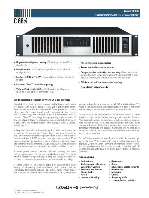
▸▸Unprecedented▸power▸density – Total output of 6800 W (4 ohms) in 2U▸▸Four▸channels▸– All channels bridgeable for 2- or 3-channel configurations▸▸Lo-Z▸or▸Hi-Z▸(70▸V▸/▸100▸V) – Selectable per channel, normal or bridged▸▸Patented▸Class▸TD▸amplifier▸topology▸▸Voltage▸Peak▸Limiter▸(VPL) – Configurable per channel to optimize each output for connected loads▸▸Phoenix-type▸input▸connectors▸▸Screw▸terminal▸output▸connectors▸Comprehensive▸protection▸and▸warning – Excessive output current, DC, high temperature, very high frequency (VHF), short circuit, open load, mains fuse protection, and soft start▸Efficient▸and▸uniform▸Intercooler®▸cooling▸NomadLink®▸network▸readyAn▸Installation▸Amplifier▸without▸CompromiseInstalled or on tour, uncompromising quality begins with supe-rior sound. Over the past decade, the sound of Lab.gruppen ampli- fiers has earned praise from renowned FOH engineers and owners of the world’s premier sound rental companies. At the core of the C Series high-power* model’s tight and transparent sound is patented Class TD technology. As a proprietary implementation of tracking Class D, Class TD approaches the exceptional efficiency of Class D while retaining the superior sonic quality of the best Class B output stages.A Regulated Switch Mode Power Supply (R.SMPS) contributes to the remarkable efficiency of the C Series high-power models, while at the same time providing stable operation even with wide fluctuations in mains voltage. R.SMPS also works in conjunction with Class TD to give extraordinary power density. More channels with more power are condensed into a smaller package, allowing C Series amplifiers to minimize rack space requirements and reduce installation costs. Extreme power density demands efficient cooling, and here Lab.gruppen’s Intercooler® proves remarkably effective. Thousands of small copper cooling fins dissipate heat, and all output devices are mounted on one row perpendicular to airflow for uniform cooling.C Series amplifiers are uniquely capable of adapting to a wide variety of demanding load conditions. Each channel has an individually configurable Voltage Peak Limiter (VPL), which allows the output to be optimized for any loudspeaker load – whether one massive subwoofer or a series of small 100 V loudspeakers. VPL works in combination with adjustable input gain to achieve maximum headroom regardless of input levels or output impedances.To assure reliability, and minimize service interruptions, C Series amplifiers offer comprehensive warning and protection features. Whenever faulty wiring, improper use, or extreme ambient tempera-tures threaten trouble, a C Series amplifier gives clear and accurate warning indications. Protection measures are inserted only when dangerous thresholds are passed. Conditions are re-checked at six-second intervals, and normal operation resumes when measure-ments return to nominal.Every C Series amplifier is ready for the NomadLink® network right out of the box. With NomadLink®, key amplifier parameters are displayed via DeviceControl software, and remote control of chan-nel mutes and power on/off is under network control. (NomadLink®requires the separate NLB 60E NomadLink®Bridge & Network Controller.)▸▸Auditoriums▸▸Performing▸Arts▸Centers▸▸Convention▸Centers▸▸Stadiums▸and▸Arenas▸▸Theme▸Parks▸▸Hotels▸▸Houses▸of▸Worship▸▸Restaurants▸▸Clubs▸▸Educational▸Establishments▸▸Boardrooms▸▸Museums▸▸Offices▸▸Shopping▸Malls▸▸Transportation▸Facilities Applications* C Series high-power models are:C 88:4, C 68:4, C 48:4, C 24:4 and C 16:4 C 68:4L a b .g r u p p e n a b ▸ S w e d e ni n t e r n a t i o n a L c o n t a c t ▸ i n f o @L a b g r u p p e n .c o m | u S & c a n a d a c o n t a c t ▸ i n f o @t c g -a m e r i c a S .c o mw w w .l a b g r u p p e n .c o mSpecifications C 68:4Item no. TDS-C684_V5GeneralNumber of channels4Peak total output all channels driven 6800 W Peak output voltage per channel 141 VMax. output current per channel 24.5 Arms Max.▸Output▸Power 16▸ohms 8▸ohms 4▸ohms 2▸ohms Hi-ZPer ch. (all ch.’s driven)650 W 1200 W 1700 W 1200 W 1600 W (70 Vrms / 100 V peak)Bridged per ch.2400 W3400 W2400 Wn.r.3200 W (140 Vrms / 200 V peak)Performance▸with▸Gain:▸35▸dB▸and▸VPL:▸100▸V THD 20 Hz - 20 kHz for 1 W<0.1%THD at 1 kHz and 1 dB below clipping <0.05%Signal To Noise Ratio>112 dBA Channel separation (Crosstalk) at 1 kHz>70 dBFrequency response (1 W into 8 ohms) +0/-3 dB 6.8 Hz - 34 kHz Input impedance20 kOhm Input Common Mode Rejection, CMR 50 dB Output impedance @ 100 Hz30 mOhmVoltage▸Peak▸Limiter▸(VPL),▸max.▸peak▸output VPL, selectable per ch. 3)141, 118, 100, 85, 71, 59, 50, 42 VVPL, when bridged 3) 1)282, 236, 200, 170, 142, 118, 100, 84 V Voltage Peak Limiter mode (per ch.)Hard / SoftGain▸and▸LevelAmplifier gain selectable (all channels) 1) – rear-panel switches 23, 26, 29, 32, 35, 38, 41, 44 dBDefault gain35 dBLevel adjustment (per ch.)Front-panel potentiometer, 21 position detented from -inf to 0 dB, hidden behind security panel/dust filter grilleConnectors▸and▸switches Input connectors (per ch.)3-pin Phoenix, electronically balanced Output connectors (per ch.)Barrier strip 2-pole screw terminalsOutput bridge mode A+B and/or C+D, inputs A and C are input source NomadLink ® network On board, 2 x RJ45 connectorsIntelligent fans (on/off)Y es, depending on presence of output signal Power on/off and Remote enable on/off Individual switches on front-panelCoolingTwo fans, front-to-rear airflow, temperature controlled speedFront-panel▸indicators Common NomadLink ® Network; Power Average Limiter (PAL) 2); Power onPer channelSignal present / High-impedance; -10 dB and -4 dB output signal; Voltage Peak Limiter (VPL); Current Peak Limiter (CPL); Very High Frequency (VHF); High Temperature; Fault; MutePowerOperating voltage, 230 V / 115 V nominal 130 -265 / 65-135 V 4)Minimum power-up voltage, 230 V / 115 V 171 V / 85 V Power Average Limiter (PAL) 2)YesSoft start / Inrush Current Draw Yes / max. 5 AMains connector 230 V CE: 16 A, CEE7; 115 V ETL: 30 A Twist Lock Dimensions▸(W/H/D)W: 483 mm (19”), H: 88 mm (2 U), D: 343 mm (13.5”)Weight 12 kg (26.4 lbs.)FinishBlack painted steel chassis with gray painted steel front ApprovalsCE, ANSI/UL 60065 (ETL), CSA C22.2 NO. 60065, FCCNote▸1): Automatic -6 dB gain compensation when bridging channels. Ch.’s A+B and/or C+D, can be bridged individually.▸Note▸2): PAL can reduce the maximum output power to keep the power supply operating safely, and/or to prevent excessive current draw tripping the mains breaker. Refer to Operation Manual.▸Note▸3): For sine waves, peak voltage output values translate to Vrms with the formula V/1.41 = Vrms. E.g. 100 V peak equals app. 70 Vrms.Hence, outputs can be set for high-impedance loads without requiring a transformer.▸Note▸4): Separate 230 V or 115 V versions available. Not selectable on the amplifier.▸All▸specifications▸are▸subject▸to▸change▸without▸notice.。
Atlona Gain 120 低阻 高阻音频电力放大器-120瓦说明书

The Atlona Gain™ 120 (AT-GAIN-120) is a compact power amplifier designed for low or high impedance applications. A mode selector switch allows it to deliver two channels of 60 watts each into 4 or 8 ohms, or a single channel of 120 watts at 70 or 100 volts. This Class-D amplifier is energy efficient, ENERGY STAR® qualified, and is also convection-cooled to allow installationStaticIf no DHCP server is available, or a static IP is required, the GAIN-120 can be set to static IP mode using the IP reset button. •Press and hold the IP RESET button for 10 seconds to switch to static IP mode. In this mode, the AT-GAIN-120 will be set to the following: IP address: 192.168.1.254 Subnet mask 255.255.0.0 Gateway: 192.168.1.1 •To switch back to DHCP , press and hold the IP reset button for 10 seconds.IP ModesDHCPBy default, the AT-GAIN-120 is set to DHCP mode. In this mode, when the AT-GAIN-120 is connected to the Local Area Network (LAN), it will automatically be assigned an IP address by the DHCP server (if available).Accessing the webGUIThe AT-GAIN-120 includes a built-in webGUI, which allows easy remote management and control of all features. Follow the instructions below to access the webGUI.1. Make sure that an Ethernet cable is connected between the LAN port on the AT-GAIN-120 and the network.2. Launch a web browser and enter the IP address of the unit.3. The AT-GAIN-120 Login page will be displayed.4.Enter the following information on the Login page.Login:admin Password: Atlona5. Click the Login button.6.Refer to User Manual for detailed operation of the webGUI.AMS 2.0For easy configuration of Atlona devices , AMS 2.0 is available from https:///ams for free. Two options can be used for installation: The free Linux based software download or the easy to install server hardware (AT-AMS-HW).Once AMS has been set up:1. Open a browser on the same network as AMS 2.0 and go to the IP address of AMS 2.0. View the AMS 2.0 installation instructions on how to find the IP address of the software.2. Enter the login information on the AMS 2.0 web page, then click the Login button.3.View the AT-GAIN-120 manual for routing and configuration information.。
高功率脉冲放大器产品说明书

TWT High Power Pulse AmplifierFEATURES• Small form factor 5U chassis• Modern TWT design with internal monitoring • Instantaneous L-Band octave bandwidth• Suitable for linear high peak pulse applications • Built-in protection circuits • Versatile interface options • High reliability and ruggednessRF SPECIFICATIONSParameterSpecification NotesOperating Frequency Range 1.0 - 2.0 GHz Power Output @ Peak Pulse 4.0 KW MinPower Ripple+/- 0.1 dB (maximum) Output Peak Power+66 dBm (minimum) Input Power (for Rated Output)0 dBm (typical)Spurious Output0-250 Hz> 250 Hz-55 dBc (minimum) -60 dBc (minimum)Load VSWR 2:1 (maximum) Output VSWR Protection 100% Duty Cycle 6% Gain (for rated output) 66 dB (adjustable) Gain Stability 0.25 dB/24 hours (typical)*Optionally customer may specify maximum input power.RF SAMPLINGSPECIFICATIONSMODULATION SPECIFICATIONSParameter SpecificationNotes Pulse Width 0.1µs to 100µs Repetition Rate 0-500 kHz Rise and Fall Time 100 ns (maximum) Droop 0.01 dB/µs (maximum) Pulse Jitter +/- 2.5 ns Video/RF Throughput Delay 300 ns (maximum)Parameter SpecificationNotes RF Output Pulse Video Sample + 10 mv/kw into 50Ω RF Output Power Sample -40 dB RF Interstage Power Sample -20 dB RF Input Power Sample -20 dBTWT High Power Pulse AmplifierELECTRICAL SPECIFICATIONSParameter Specification Notes Primary Input Power Mains 240+/-10%/1p/60HzPrimary Power Consumption 1.3 kVa (maximum)Elapsed Time Meter 00,000.00 hours | 100%Modulation Input Pulse +5v TTLDigital Interface Ethernet (LAN)/RS-232*LAN OptionalMECHANICAL SPECIFICATIONSParameter Specification NotesFront Panel Standard RETMA .125" thick withslotted mounting holesDimensions - Front Panel Depth Width: 19"Height: 8.75"Chassis: 26"Overall: 28"Finish - Front Panel Chassis Anodize, Color BlueWeight 85 Pounds (typical)Cooling Self-Contained Forced AirENVIRONMENTAL SPECIFICATIONSParameter Specification Notes Operating Temperature 0.1 to +50C | Derate to 10C for 10,000-foot OperationStorage Temperature -40 to +85CHumidity 0 to 95% non-condensingAltitude 0 to 10,000 feet above sea level, 50,000non-operatingTWT High Power Pulse AmplifierDIGITAL INTERFACE RS-232RS-232 interface provides ability to remotely operate, monitor, control and adjust the system. IEEE-488, an optional feature, provides the ability to remotely operate, monitor and control operation of the amplifier. Any fault condition latches information. Ethernet (LAN) and RS-422 are also available. Software is provided to operate with MS Windows.CONDITIONS MONITORED AND INTERLOCKEDParameter Specification NotesVSWR 0.00% Body Voltage 00.00 kV Body Current* 00.00 mA Heater Voltage* 0.00 V Heater Current* 0.00 A Grid Bias Voltage* 000.00 V Grid Pulse Amplitude* 000.00 V Access Lid Interlock Fault Excessive Temperature Fault PRF Limit* Fault Pulse Width Limit* Fault Pulse Received Yes/No* The following parameters and associated High/Low limits are factory adjustable (including Cathode Voltage).CONTROLS & INDICATORS Front Panel • Switches• Illuminated Status Monitor • Off/Standby/Operate/Reset• Warm-up/Standby/Operate/ResetAccessories Supplied (1-Each) • Maintenance Manual• Primary Input Power Mating Connector • CD ROM: Computing Operating SoftwareConnectors Type NotesRF Input (Rear Panel) N(f) RF Output (Rear Panel) SC(f) RF Samples (Front Panel) N(f) RF Output Pulse Video Sample (Front Panel)BNC(f) Modulation Input Panel (Front Panel) BNC(f)Conditions Monitored and Interlocked Adjustable Parameters Notes RS 232 DB 25 F (Rear Panel) IEEE-488 (Optional) GPIB (Rear Panel) Ethernet (Optional) RJ-45 Primary Power Input NEMA L5-20 (Three Wire) Remote Control DB-25 NOTE: RF Connectors may be optionally located on either the front or rear panels.TWT High Power Pulse AmplifierCONTROLS AND INDICATORS (OPTIONAL)Operation The front panel display is active whenever TWTA is poweredon.Standard Mode Warm-up (with time remaining)StandbyOperate (with pulse indication)Fault (with fault name)Diagnostics Mode Following parameters are available through menu:Heater voltage, heater current, grid bias voltage, grid drivevoltage, helix voltage, helix current, collector voltage,collector current, cathode current, VSWR.OPTIONSOption E-rack Mounting Allows the unit to be mounted in a standard EAI 19” rackcabinet, incorporating side mounted sides.Option G- 400Hz Provides for 400 Hz AC frequency operation.Option J- Outputs Isolator Protects the TWT from varying load VSWR conditions.Insertion loss of the isolator will lower the output powerslightly (0.5 dB typically) from normal. Call the factory forconfiguration and dimensions (isolator may be providedexternally).Option X- Reflected Power Protection Protects the TWT from high load VSWR and intended for useon ultra-wide band or high-power units for which isolatorsare not normally available. Consists of a coupler and detectorthat turns the TWTA off when excessive reflected power issensed. Typical insertion loss is 0.5 db.。
功放的说明书
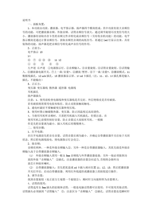
说明书一、面板布置:1、本功放由功放、播放器、电平指示器、扬声器四个模块组成。
其中功放有放大音频信号的功能,可把播放器音频、外接音频、话筒音频信号放大,通过调节旋钮可改变信号的大小。
播放器有读取内存卡里的音频文件并转化成音频信号(另有收音机功能)的功能。
电平指示模块是通过计算音频信号,获取音频里音调的高低信号,再通过led灯显示出来,具有装饰的功能。
扬声器是把音频信号转化成声音信号的作用。
2、正前方:电平指示 1314⑥⑦⑧⑨⑩ 11 12①②③④⑤左声道右声道①电源指示灯、②音频输入、③音量旋钮、④话筒音量旋钮、⑤话筒输入、⑥播放器电源开关、⑦上一曲/音量-、⑧播放/暂停、⑨下一曲/音量+、⑩播放模式、11数据线插孔、12 usb插孔、13播放器显示屏、14 sd卡插孔(注:11、12、14插孔都是输入插孔,不能输出)3、正后方:变压器变压器线散热器遥控器电源线耳机插孔扬声器插头注意:1、使用前检查电源线和变压器线是否完好,外层绝缘皮是否有破损,若有破损则需要用电胶布粘住,防止皮肤接触而触电。
2、通电时最好不要触碰变压器和变压线。
3、使用时禁止触碰散热器、变压器,防止因温度过高而烫伤。
4、当使用耳机听音频时,只需把耳机插入耳机插孔,但要注意,在使用耳机之前要控制好音量,防止音量过大而损坏耳机。
一般操作是先把音量调为最小,插入耳机后再慢慢增大。
二、使用步骤:1、打开电源:在打开电源前先把音乐音量,话筒音量④调为最小,并确定自带播放器开关⑥处于关闭状态。
然后把电源线接电,则电源指示灯会亮①。
2、接音频:音频有两种,一种是外接音频输入②,另外一种是自带播放器输入,其优先级是外接音频输入高于自带播放器音频输入。
(1)外接音频输入需用一根3.5mm音频线与外界播放器连接,另外一端必须接到功放的外接“音频输入”②插孔,注意播放器的音量③应适当,否则将会烧坏功放芯片和损坏喇叭。
(2)自带播放器输入:首先把优盘或sd卡插入相应位置11、12、13,然后把播放器开关打开⑥,启动自带播放器。
FR-PA07 面板操作说明书
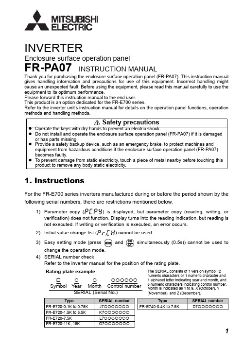
Enclosure surface operation panelFR-PA07INSTRUCTION MANUALINVERTERThank you for purchasing the enclosure surface operation panel (FR-PA07). This instruction manual gives handling information and precautions for use of this equipment. Incorrect handling might cause an unexpected fault. Before using the equipment, please read this manual carefully to use the equipment to its optimum performance.Please forward this instruction manual to the end user.This product is an option dedicated for the FR-E700 series.Refer to the inverter unit's instruction manual for details on the operation panel functions, operation methods and handling methods.1.InstructionsFor the FR-E700 series inverters manufactured during or before the period shown by the following serial numbers, there are restrictions mentioned below.1)verification) does not function. Display turns into the reading indication, but reading is not executed. If writing or verification is executed, an error occurs.2)3)4)SERIAL number checkRefer to the inverter manual for the position of the rating plate.Rating plate example The SERIAL consists of 1 version symbol, 2 numeric characters or 1 numeric character and 1 alphabet letter indicating year and month, and 6 numeric characters indicating control number.Month is indicated as 1 to 9, X (October), Y (November), and Z (December).{{{{{{{{SymbolYear Month Control number SERIAL (Serial No.)TypeSERIAL number TypeSERIAL number FR-E720-0.1K to 0.75K J7{{{{{{{FR-E740-0.4K to 7.5K D7{{{{{{{FR-E720-1.5K to 5.5K K7{{{{{{{FR-E720-7.5K L7{{{{{{{FR-E720-11K, 15KG7{{{{{{{2.Connection2.1Installation using a connection cable (FR-CB20 )Securely insert one end of connection cable into the PU connector of the inverter and the other end into the connection connector of the FR-PU07 along the guides until the stoppers are fixed.2.2Removal when the connection cable (FR-CB20 ) is usedHold down the tab (stopper) at the cable end and gently pull the plug.NOTEy Install the FR-PA07 only when the front cover is installed.For details of the connection cable (FR-CB20 ), refer to the connection cable (FR-CB20 ) instruction manual.s and functions of the operation panel (FR-PA07)*Both PU and EXT are off on the inverters manufactured during or before the period shown by the serial numbers described on page 1.MODE SETSTOP RESET REV FWDPU EXT4.Operation*the serial numbers described on page 1.Refer to page 1)*DE SETP E DE SETP EDE SETP EDE SETP EDE SETP ETPU EXTTPU EXTHz AHz ARUN MON EXTPUHz ARUN MONMODE SMODE SMODE S TPU EXTDE SETP EPU operation mode (output frequency monitor)M o n i t o r /f r e q u e n c y s e t t i n gValue change Output currentmonitor P a r a m e t e r s e t t i n gParameter setting modeF a u l t s h i s t o r y(Example)and frequency flicker.Frequency setting has been written and completed!!Output voltagemonitorFaults history clearInitial value change listParameter write is completed!!Parameter and a setting value [Operation for displaying faults history] (Refer to the inverter manual)Past eight faults can be displayed.(The latest fault is ended by ".".)When no fault history exists, is displayed.4.2Operation lock (Press [MODE] for a while (2s))y Set "10 or 11" in Pr . 161y display appears.)yOperation using the setting dial and key of the FR-PA07 can be made invalid to prevent parameter change, and unexpected start or frequency setting.POINTSet "10 or 11" (key lock mode valid) inPr. 161 Frequency setting/key lock operation selection .Operation Display1.Screen at powering onThe monitor display appears.2.3.mode.appears.)4.(Pr. 161) appears.5.6.7.to set.8.Notey Release the operation lock to release the PU stop by key operation.4.3Use the setting dial like a potentiometer to perform operationPOINTSet "1" (setting dial potentiometer mode) in Pr. 161 Frequency setting/key lock operation selection .Changing exampleChanging the frequency from 0Hz to 60Hz during operationOperation Display1.Screen at powering onThe monitor display appears.2.3.Change the Pr. 161 setting to "1".(Refer to page 5 for change of the setting.)4.5.set frequency.If flickering "60.00" turns to "0.00", the Pr. 161 Frequency setting/key lock operation selection setting may not be "1".Independently of whether the inverter is running or at a stop, the frequency can be set byPr. 295 Magnitude of frequency change setting to change the5.Specifications5.1Standard specificationsItem SpecificationsAmbient temperature-10°C to +50°C (non-freezing)Ambient humidity90%RH or less (non-condensing)Storage temperature-20°C to +60°CAmbience Indoors (free from corrosive gas, flammable gas, oil mist, dust and dirt) Altitude, vibration Maximum 1000m above sea level for standard operation. 5.9m/s2or less Power supply Power is supplied from the inverter.Connection method Connection using the parameter unit connection cable (FR-CB20 ) 5.2Outline drawing and panel cutting drawing<Outline drawing><Panel cutting drawing>。
Pyramid PA105 PA205 PA 放大器说明书

®StudioPRO High Performance Professional AudioMODEL:PA105/PA205PA AMPLIFIERINTRODUCTIONYour New PYRAMID PA105/PA205PA AMPLIFIER gives you the power and versatility you need in a professional sound system.The amplifier's wide frequency response makes it suitable for amplifying music or vocal program material.It can be used for live bands,office paging systems, public announcements,or a variety of other installations.Please read this manual throughly before you attempt to set up and use the amplifier.It contains a range of installation suggestions as well as instructions to ensure safe usage.Installed properly,you can expect years of trouble-free service from this product.FEATURES AND CONTROLSFRONT PANEL-PA105/PA2051.Power On/Off2.Phone JackLets you connect a pair of stereo headphones for private listening or cueing(monitoring)sound prior to"airing"it.3.MIC1&MIC2JackAllows you to connect up to two6.35mm type microphone.4.LED Level Display Meter5.Three Input Sources Mixing ControlsControls the sound level for each of the audio input sources.PHONO/AUXAllows you to select and connect an alternative high level(AUX/CD)or low level(PHONO)audio sound source.6.Tone Control(PA105)Lets you adjust the sound frequency to the acoustics of a particular performance environment.7.100Hz,1kHz,&8kHz Equalizer Controls(PA205)To enhance the sound or tailor the high,midrange,and low frequencies for each audio source input to the acoustics of a particular performance environment,you can adjust these equalizer tone controls.8.Master VolumeLets you adjust the overall sound level.REAR PANEL-PA105/PA2059.Voltage SwitchThe amplifier has selectable input voltage from110V/60Hz which is the standard in USA and CANADA.You can also switch the input voltage to220V/50Hz for EUROPEAN operation.Please make sure the switch is in the proper position before operating,otherwise severe damage will result not cover by the warranty.Please also replace the fuse with proper rating in this situation (see the SPECIFICATIONS for the fuse rating).10.Unswitched AC Accessory Outlet-300W MAX.11.DC4A/12V Input Jack(PA105)Allows you to power the amplifier from12-volt battery source.12.AUX/CD Input JackAllows you to connect any high level sound source,such as a CD player,tape deck,or tuner,to the CD/AUX jack.13.PHONO Input JackYou can connect a low level audio input source,such as a magnetic cartridge turntable to theL PHONO and R PHONO jacks.14.PHONO and AUX/CD Input SelectorLets you select the input source you want to connect to the amplifier.15.MIX BUS JackAllows you to connect another PA105/PA205to this jack to double the size of your PA system.16.Push-Terminal ConnectorsLet you easily connect speaker wires directly to the amplifiers.INSTALLATION GUIDELINESConnecting the GND(GROUND)screw terminalI f you connect a low level audio input source(turntable)to the PHONO,please connectyour turntable's ground wire(usually black or green)to the amplifier's GND terminal,to avoid a low frequency hum.You can also use this screw to ground any other system connection.Input connectionsThe PA105/PA205accept a board range of input sources,including:Microphones(up to two simultaneously)Compact Disc(CD)playerCassette,Reel-to-Reel or other tape playerRadio TunerMagnetic Cartridge TurntableConnecting microphonesThe MIC1and MIC2jacks permit you to connect two microphones with6.35mm plug.Connecting a CD or tape player,or tunerIn this Situation,set the PHONO and AUX/CD SELECTOR switch to the AUX/CDConnecting a turntableIn this Situation,set the PHONO and AUX/CD SELECTOR switch to the PHONO.Speaker connectionsOne or more speakers(4,8,or16-Ohm)speakers can be connected to the amplifier with or without transformers.However,before you connect any speaker to the amplifier,the total speaker impedance must be calculated in order to avoid damage to the amplifier.A total speaker impedance greater than16Ohms or less than4Ohms can be cause this damage to occur.System2:Two(or more)speakers in series 1.Connect the LEFT SPEAKER(-)to the amplifierCOMMON terminal.2.Connect the LEFT SPEAKER(+)to the RIGHTSPEAKER(-).3.Connect the RIGHT SPEAKER(+)to the amplifier's4-Ohm,8-Ohm,or16-Ohm terminal,depending on the TOTAL IMPEDANCE of the two speakers.If each speaker has an impedance of8Ohms,the total speaker impedance in this series configuration is16Ohms.To begin with,in order to ensure equal volume from each speaker,all connected speakers should have the same impedance.A proper total impedance with the4to16Ohms range can be achieved by combining series and paralled speaker connections.Please see the diagrams which follow the same impedance.Finally,always use the shortest length of speaker wire possible of proper ually,18-gauge wire is adequate for lengths under25feet,while16-gauge is used for greater lengths.System1:Single speaker system1.Connect the speaker(-)terminal to the amplifierCOMMON terminal2.Depending on the speaker being used,connect thespeaker(+)terminal to the amplifier's4-Ohm,8-Ohm or16-Ohm amplifier terminal.or Tape Playerthe Phono PositionNOTE:ADDITIONAL SPEAKERS MAY BE INCLUDED IN SERIES,BUT IT IS NECESSARY TO CALCULATE TOTAL IMPEDANCE,AND CONNECT THE SPEAKER CIRCUIT TO A TERMINAL OF APPROPRIATE IMPEDANCE.FOR EXAMPLE,IF THREE SPEAKERS OF 4-OHM ARE USED,TOAL IMPEDANCE IS 12OHMS,YOU SHOULD CONNECT TO THE 16-OHM TERMINAL.System 3:Two (or more)speakers in parallel1.Connect the LEFT SPEAKER (-)to the RIGHT SPEAKER (-).2.Connect BOTH the LEFT SPEAKER (-)and the RIGHT SPEAKER (-)to the amplifier COMMON terminal.3.Connect the LEFT SPEAKER (+)to the RIGHT SPEAKER (+).4.Connect BOTH the LEFT SPEAKER (+)and RIGHT SPEAKER (+)to the amplifier 4-Ohm,8-Ohm or 16-Ohm terminal,depending on the TOTAL IMPEDANCE of the two speakers.If each speaker has an impedance of 8-Ohm,the total speaker impedance in this parellel configuration is 4Ohms.4.Connect the speakers'(-)terminals to the amplifier's COMMON terminal.5.Connect the speakers'(+)terminals to the amplifier's 4-Ohm,8-Ohm,or 16-Ohm terminal,depending on the TOTAL IMPEDANCE of the FOUR SPEAKERS.See the chart below for some samples system suggestions:COMBINATION OF TWO SERIES PAIRS IN PARALLELSERIESPARALLELTOTALUse this TO EACH PAIR TO TWO PAIRS IMPEDANCE amp (net impedance)(net impedance)IN THIS TYPE terminal 4-OHM +4-OHM 8-OHM +8-OHM 4-OHM4-OHM(8OHMS)(4OHMS)8-OHM +8-OHM 16-OHM +16-OHM8-OHM 8-OHM(16OHMS)(8OHMS)16-OHM +16-OHM 32-OHM +32-OHM 16-OHM 16-OHM(32OHMS)(16OHMS)SERIES/PARALLEL VARIATIONSAlthough the description above is for combining TWO SERIES PAIRS in a PARALLEL hook up,you may also select to combine a SERIES PAIR and a PARALLEL PAIR in a PARALLEL hook up.Simply be sure you have properly calculated the total impedance,and connect the (+)speaker circuit wire to the proper amp terminal.For example,if you use a SERIES PAIR of 8-Ohms speakers (the total impedance is 16ohms)and a PARALLEL PAIR of 8-Ohms speakers (the total impedance is 4ohms)in a PARALLEL hook up,the TOTAL IMPEDANCE of this system is 3.2OHMS,so you should connect the (+)speaker circuit wire to the 4-OHM terminal.System 4:Four speakers in series/parallel combination1.Group the four speakers into two pairs.2.Connect each pair of speakers in SERIES (see system 2above).If you connect 8-ohm speakers,the total impedance of each pair is 16ohms.3.Connect the two pairs of speakers in PARALLEL,If you connect 8-ohm speakers,the total impedance of both pairs is 8ohms.Note:If each of the four speakers is 8ohms,the total speaker impedance of the combined series/parallel connection described above is also 8ohms.Likewise,the total speaker impedance is 4or 16ohms,if the speakers are 4or 16ohms respectively.See the chart below for some samples system suggestions:COMBINATION OF ONE SERIES PAIR AND ONE PARALLEL PAIR IN PARALLELSERIES TO ONE PARALLEL TO ONE TOTAL IMPEDANCE Use this SPEAKER PAIR SPEAKER PAIR COMBINING TWO amp(net impedance)(net impedance)PAIRS IN PARALLEL terminal8-OHM+8-OHM8-OHM+8-OHM 3.2OHMS4-OHM(16OHMS)(4OHMS)16-OHM+16-OHM8-OHM+8-OHM 3.6OHMS4-OHM (32OHMS)(4OHMS)4-OHM+4-OHM16-OHM+16-OHM 4.0OHMS4-OHM (8OHMS)(8OHMS)8-OHM+8-OHM16-OHM+16-OHM 5.3OHMS8-OHM(16OHMS)(8OHMS)This example shows for the first three systems in chart. In this case,4-Ohm terminal is used your system impedance may be varied depending on the impedances of the individual speakers,and may reguire hook up to the8or16Ohms terminal.System5:Connecting speakers with transformers 1.Locate the input taps on your transformer.These taps are on side of the transformer,and are rated in watts, 10,5,2.5,ually,each speaker in a system uses the same wattage tap.Connect the selected tap to the amplifier70V RMS terminal.If you wish a particular speaker to have a higher volume level,connect the wire from70V RMS to a higher wattage tap on the transformer.2.Connect the transformer's COMMON tap on the primary side to the amplifier COMMON terminal.3.Connect the speaker's(+)terminals to the transformer's secondary tap that matches the speaker's TOTAL IMPEDANCE.Locate on the opposite side of the transformer,these secondary taps are outputs,and are rated in Ohms4,8or16.4.Connect the speaker's(-)terminals to thetransformer's COMMON tap on the secondary side. NOTE:Before connecting the speakers,please be sure the total wattage of the primary tap you use doesnot exceed the amplifier's maximum power rating,PA10520W and PA20540W.ALSO:Avoid,where possible,multiple connections to the70V RMS and COMMON terminals.Using headphonesTo listen privately,or to monitor sound sources, connect a pair of low impedance stereo headphones (not supplied)with6.35mm plug into the PHONES jack on the amplifier front panel.Please listen safely.Follow these recommendations: Do not listen at extremely high volume levels.Extended, high-volume listening can lead to permanent hearing loss.Always start with the volume control set to a LOW level BEFORE you put the headphones on.Then gradually increase the volume as necessary.Connecting to standard AC powerAfter making all other connections,set the POWER switch to OFF position.Then connect the power cord to a standard AC outlet. Connecting to4A/12V DC power(PA105)You can power the amplifier from your vehicle's12-volt battery.Connect the supplied DC power cable's barrel plug to DC12V IN jack on the amplifier,and then connect the cable's other end to the12-volt accessory socket on the vehicle,such as the cigarette-lighter socket. CAUTIONS:PLEASE UNPLUG THE AC POWER CORD BEFORE CONNECTING THE DC POWER CABLE FOR THIS12V POWER USAGE,AND DISCONNECT THE DC POWER CABLE BEFORE PLUGING IN THE AC POWER CORD FOR AC POWER USAGE.THE VEHICLE USING FOR THIS POWER SOURCE MUST HAVE A NEGATIVE GROUND ELECTRICAL SYSTEM.IF YOU ARE NOT SURE OF IT,PLEASE CHECK WITH YOUR VEHICLE'S DEALER.Turning the amplifier on1.Turn on the audio input source equipment which is connected to the amplifier INPUT jack.2.Set all volume levels(MASTER,MIC1,MIC2,and PHONO/AUX)to their minimum level settings.3.Press the power switch to turn the amplifier on.4.Adjust the controls of MIC1,MIC2,and PHONO/AUX to the achieve desired volume and balance.Using the LED power meterThe meter LED position indicate the amplifier output power.Using the MASTER volume controlThe MASTER volume control increases or decreases output level gain.To obtain best performance with the least distortion, be sure to adjust the output level so that the LED meter does not continuallyexceed the right extreme of the meter's range. CAUTION:Setting output level too high can overdrive the amplifier,causing permanent damage.Using the MIX BUS jackYou can connect another PA105/PA205to this jack to double the size of your PA system.This lets you use up to four microphones and two turntables(or two auxiliaryies)sound souces. Use a shield cable with phono plugs at each end,and connect the cable between the MIX BUS jacks on the back of two amplifiers.For the best results,do not use a cable longer that6 feet.SpecificationsOutput Power at THD10%,1kHz......................................20W(PA105)/40W(PA205) Maximum Power....................................80W(PA105)/120W(PA205) THD at1W,1kHz Low-Pass FilterMIC1...................................................................1% MIC2...................................................................1% AUX/CD..............................................................1% PHONO...............................................................1% Frequency Response(at1W,+/-3dB)MIC1.................................................80Hz-20kHz MIC2.................................................80Hz-20kHz AUX/CD............................................80Hz-20kHz PHONO(RIAA100Hz/10kHz)......+13dB/-13.5dB Input Sensitivity(at10%THD,1kHz)MIC1.............................................................2.5mV MIC2.............................................................2.5mV AUX/CD.........................................................150mV PHONO...........................................................3.5mV Signal-Noise Ratio(Input Shorted)with WTD MIC1................................................................60dB MIC2................................................................60dB AUX/CD...........................................................70dB PHONO............................................................60dB Noise Level(Input Shorted)..............................0.75mV Tone Control(PA105)-15dB(High Cut at10kHz)Equalizer Control Range(PA205)100Hz.......................................................+/-10dB 1kHz.........................................................+/-10dB 8kHz.........................................................+/-10dB Power Requirement120V AC,60Hz/240V AC,50Hz4A12V DC(OPTION OF PA105)Power Fuse120V AC........................1.2A(PA105)/1.5A(PA205) 240V AC......................0.6A(PA105)/0.75A(PA205) Dimensions H x W x D,31/3x123/4x89/10(inches)85x324x226(mm)Weight,(kg)(PA105)3.56kgs/(PA205)3.92kgsPYRAMID AMPLIFIERS CAR AMPLIFIERS。
XL1875A 30W 4A 60V高电压大功率音频功率放大器说明书

30W 4A 60V 高电压大功率音频功率放大器 XL1875ARev 1.1 特点⏹ 输入电压范围:16V~60V ⏹ 输出电流能力可达4A 以上 ⏹ 输出功率可达30W 以上 ⏹ 内置输出过功率保护功能 ⏹ 内置输出短路保护功能 ⏹ 内置输出过压保护功能 ⏹ 内置限流保护功能 ⏹ 内置热关断保护功能 ⏹ 低静态电流:20mA⏹ 低失真:0.015%,1kHz ,20W ⏹ 开环增益可达90dB 以上 ⏹ 94dB 纹波抑制比 ⏹ TO220B-5L 封装应用⏹ 车载音频功放 ⏹ 舞台音响 ⏹ 多媒体音箱 ⏹ 开放式移动音响系统描述XL1875A 是一款AB 类单通道音频功率放大器,专为高电压、大功率、高效率优化设计。
XL1875A 具有极低的静态电流,最大限度的降低系统功耗。
XL1875A 高效的高压设计实现出色音频性能, 在30W 输出功率下最大限度的提高了音频信号的保真度。
XL1875A 内置过功率保护、限流保护、输出过压保护、输出短路保护、热关断保护功能,极大程度地提高了芯片的可靠性、易用性、稳定性。
XL1875A 在输入电压±25V ,负载阻抗为4Ω或8Ω的情况下,输出功率可达到20W@THD=0.015%;在输入电压±30V 的情况下,负载阻抗为4Ω或8Ω的情况下输出功率可达到30W@THD=1%。
高度集成方案能够缩小印制电路板空间,同时将外部元器件减至最少。
图1. XL1875A 封装引脚配置VCC IN-IN+OUTPUTMetal Tab VEEVEE图2. XL1875A 引脚配置表1.引脚说明功能方框图OUTPUTIN-IN+图3. XL1875A 功能方框图典型应用1K 22uF 20K(双电源)C4R2R1(单电源)图4. XL1875A 系统参数测量电路订购信息绝对最大额定值(注1)注1:超过绝对最大额定值可能导致芯片永久性损坏,在上述或者其他未标明的条件下只做功能操作,在绝对最大额定值条件下长时间工作可能会影响芯片的寿命。
op07中文资料
op07中文资料一、引言本文档旨在为读者提供关于OP07运算放大器的中文资料。
OP07是一种高性能精密运算放大器,被广泛应用于工业控制、仪器仪表和传感器信号调理等领域。
本文将介绍OP07的基本特性、电路应用、性能参数等内容,以帮助读者更好地了解和应用OP07。
二、OP07概述OP07是由美国ADI(Analog Devices Inc.)公司推出的一种低噪声、低失调、高增益的运算放大器。
其内部电路采用了差动输入、差动输出的架构,使其具有良好的共模抑制比和噪声性能。
OP07采用超低温漂技术,使其在温度变化较大的环境下依然能提供稳定的性能。
三、OP07特性1. 低噪声OP07的噪声系数非常低,通常在10nV/√Hz以下。
这使得OP07能够处理微弱信号并提供高信噪比的放大功能。
2. 低失调OP07具有低失调和低温漂特性,其失调电压和失调电流均较小。
这使得OP07能够准确放大输入信号,不会引入过多失真。
3. 高增益OP07的开环增益非常高,通常在100dB以上。
高增益使得OP07对输入信号的放大能力更强,可适用于高精度、低噪声的应用场景。
4. 宽电源范围OP07的电源电压范围较宽,通常可以工作在±15V的电源电压下。
这使得OP07适用于不同电源供电的应用场合。
四、OP07应用OP07广泛应用于各种需要高精度、低噪声放大的场合,下面列举了一些常见的应用示例:1. 传感器信号调理OP07可以用于处理传感器输出信号,提供高增益、低噪声的放大功能。
例如,温度传感器、压力传感器、光电传感器等信号的放大和调理。
2. 工业自动化OP07可用于工业控制中的PID控制、测量仪表和反馈控制等场合。
其高精度、低噪声的特性能够提供稳定和精确的控制。
3. 仪器仪表OP07可用于精密仪器仪表中的放大和信号调理,如电压测量仪、电流测量仪、频率计等。
其高性能可以提供准确的测量结果。
4. 数据采集OP07适用于数据采集系统中的信号放大和调理。
几种常用集成运算放大器的性能参数
几种常用集成运算放大器的性能参数1.通用型运算放大器A741(单运放)、LM358(双运放)、LM324(四运放)及以场效应管为输入级的LF356都属于此种。
它们是口前应用最为广泛的集成运算放大器。
卩通用型运算放大器就是以通用为LI的而设计的。
这类器件的主要特点是价格低廉、产品量大面广, 其性能指标能适合于一般性使用。
例2.高阻型运算放大器,IIB为儿皮安到儿十皮安。
实现这些指标的主要措施是利用场效应管高输入阻抗的特点,用场效应管组成运算放大器的差分输入级。
用FET作输入级,不仅输入阻抗高,输入偏置电流低,而且具有高速、宽带和低噪声等优点,但输入失调电压较大。
常见的集成器件有LF356、LF355、LF347 (四运放)及更高输入阻抗的CA3130、CA3140等。
Q这类集成运算放大器的特点是差模输入阻抗非常高,输入偏置电流非常小,一般rid> (109^1012)3.低温漂型运算放大器在精密仪器、弱信号检测等自动控制仪表中,总是希望运算放大器的失调电压要小且不随温度的变化而变化。
低温漂型运算放大器就是为此而设讣的。
訂前常用的高精度、低温漂运算放大器有0P-07、0P-27、AD508及ill M0SFET组成的斩波稳零型低漂移器件ICL7650等。
4.高速型运算放大器s,BWG>20MHzo PA715等,其SR二50〜70V/u在快速A/D和D/A转换器、视频放大器中,要求集成运算放大器的转换速率SR 一定要高,单位增益带宽BWG 一定要足够大,像通用型集成运放是不能适合于高速应用的场合的。
高速型运算放大器主要特点是具有高的转换速率和宽的频率响应。
常见的运放有LM318、5.低功耗型运算放大器W,可采用单节电池供电。
P A O U前有的产品功耗已达微瓦级,例如ICL7600 的供电电源为1. 5V,功耗为10 u山于电子电路集成化的最大优点是能使复杂电路小型轻便,所以随着便携式仪器应用范围的扩大,必须使用低电源电压供电、低功率消耗的运算放大器相适用。
PA1011功率放大器用户手册
VI
PA1000 系列功率放大器用户手册
快速入门
RIGOL
第1章 快速入门
本章介绍 PA1011 功率放大器的前后面板和用户界面,以及首次使用 仪器时的准备工作。
一般性检查
当您得到一套新的 PA1011 功率放大器,请按以下步骤进行检查。
1. 检查是否存在因运输造成的损坏 请保留被损坏的货运包装或防震材料,直到货物经过完全检查且 仪器通过电性和机械测试。 如果因运输造成仪器损坏,请通知运输部门和负责此业务的 RIGOL经销商,RIGOL会安排维修或更换。
状态指示灯
Power:红灯亮,表示电源连接成功。 Output:绿灯亮,表示输出开关已打开。 Link:黄灯亮,表示USB连接成功。
1-2
PA1000 系列功率放大器用户手册
快速入门
后面板
USB Device 电源输入端口
风扇散热孔
RIGOL
图 1-2 PA1011 后面板视图
1. 电源输入端口 请使用附件提供的电源线连接该端口,电源输入为 12V,4A 的 信号。
2. 连接仪器电源 请使用附件提供的电源线连接仪器并给仪器上电。
3. USB 连接及驱动安装 请使用附件提供的 USB 数据线,将仪器与计算机进行通信连接。 首次将仪器成功连接到计算机后,计算机画面会弹出硬件安装向 导对话框,如下图所示:
PA1000 系列功率放大器用户手册
1-5
RIGOL
快速入门
! 注意
请勿使用其它输出类型的适配器给 PA1011 供电,否则会造 成仪器性能下降或永久性损坏。
2. USB Device 通过 USB 数据线将 PA1011 与计算机相连。
! 注意
在操作 PA1011 时,请确认没有遮挡物遮住 PA1011 侧面的 通风孔和后面板的风扇散热孔,以免影响其正常工作。
PA纯后级广播功放说明书

P A纯后级广播功放说明书集团标准化办公室:[VV986T-J682P28-JP266L8-68PNN]OWNER’S MANUALBefore operating, please read this manual completely.PA3002PA4002PA5002Public AddressAmplifiersFEATURESTransformer isolated 100V, 70V and 4 Ohms speaker outputs.5 LED indicator for status display.XLR socket and mm jack for link convenient.Output circuit shorting protection & display.Series amplifiers of high output power available.AMPLIFIER FRONT VIEW1. AC power switch (1 is power on andthe “power LED ” is on )2. POWER LED indicator3. CLIP LED indicator (Please reduce4. the gain to prevent severelyclippedwaveforms reaching the loudspeakers)5. SIGNAL LED indicator(Output level) 6. PROT LED indicator (DC oroutput circuit shorted indicator) 7. TEMP LED indicator (high temperature indicator) 8. Volume (input attenuator) 9. Unit’s fan exhaust windowAMPLIFIER REAR VIEW and CONNECTIONS1. fan intake window2. COM. output3. 4~16 output4. 70V output5. 100V output6.220V AC fuse7. XLR input 8. socket input 9. socket link 10. XLR link11. 220VAC power cordOPERATING PRECAUTIONS1 2 3 4 5 6 7 8Make sure the AC main voltage is correct and is the same as that printed on the rear of the amplifier. Damage caused by connecting the amplifier to improper AC voltage is not covered by the three-year US warranty.Make sure the power switch is off before making any input or output connections. It is always a good idea to have the gain controls turned down during power-up to prevent speaker damage if there is a high signal level at the inputs.CONNECTING INPUTSInput connections are made via either the 3-pin XLR -type connectors (Figure 1) or mm sockets on the rear side of the amplifier.CONNECTING OUTPUTSLoad can be connected using banana plugs or spade lugs. A black binding post is considered “COM”, while the three red binding posts are considered “hot”, and the voltage is 38V (different from the model ), 70V , and 100V .Note:Never connect the “hot ”terminals together.When connecting load (speakers ), it is better to use one pair of output terminals only.If the PROT Led goes on steadily while power has been turned on and signal has been fed, there must be a trouble of output shorted. Please turn the unit off and correct the trouble then turn it on again.Figure 1 3-pin XLR-typeconnectorsSPECIFICATIONSHTTP:/ DSPPA ACOUSTIC TECHNOLOGY CO., LTD.使用说明欢迎惠顾。
运算放大器OP07中文手册

Ric Common Mode Input Resistance 共模输入电阻
-
12 -
GΩ
0
±1
Input Common Mode Voltage Range 输入共模电压范 Vicm 围 0℃ ≤ Tamb ≤ +70℃
±13 ±13
3.5 -
V
12
Common Mode Rejection Ratio (Vi =Vicm min)共模 100
0℃ ≤ Tamb ≤ +70℃ RL =2KΩ ±11
Slew Rate 转换率(RL =2KΩ,CL = 100pF)
-
Gain Bandwidth Product 带宽增益(RL =2KΩ,CL = -
100pF, f = 100kHz)
Supply Current -(no load) 电源电流(无负载) ≤ Tamb ≤ +70℃ VCC = ±3V
VCC Vid Vi Tope r
Supply Voltage 电源电压 Differential Input Voltage 差分输入电压 Input Voltage 输入电压
Operating Temperature 工作温度
Tstg Storage Temperature 贮藏温度
电气特性 虚拟通道连接= ± 15V , Tamb = 25 ℃(除非另有说明)
Value 数值 Unit 单位
±22 ±30 ±22 -40 +105 -65 +150
V V V to ℃
to ℃
Sym Parameter 参数及测试条件
最小 典 最 Unit
bol 符号
Input Offset Voltage 输 入 失 调 电 压 0℃ ≤ Tamb ≤
操作说明书PA放大器A
2
安全须知
使用前请确实详读本须知。 确实注意本手册中出现之安全符号及重要警告。 建议您保留本手册作为日后参考之用。
常用安全符号和警告
本手册所示安全符号和警告是为了防止因操作不当而引起的人员伤害及财产损失。请在使用本产品前详阅本手 册,务必明白各种安全符号及警告示意,以完全知晓潜在危险。
功能开关设置 ....................................................................... 9 钟声功能
话筒 1 钟声音调 ................................................................... 9 电话呼叫钟声音调 ................................................................. 9
ZONE 1(2)开关选择器与 LINE OUT 1(2)开/关联动设置 .......... 13 起动紧急控制则电源关闭,机器不能实现广播 ........................... 13 将电话呼叫输入转换为变压器平衡式 ....................................... 13
连接方法
喇叭连接方法 ....................................................................... 7 遥控电源 ON/OFF 控制的连接方法 ............................................ 7 紧急输入和控制输入端子连接 .................................................. 8 电话呼叫输入端子连接方法 ..................................................... 9
TL07xx JFET输入运算放大器说明书

+−+−IN+IN−OUTIN+IN−OUTTL072 (each amplifier)TL074 (each amplifier)TL071OFFSET N1OFFSET N2Copyright © 2017,Texas Instruments IncorporatedProductFolder Order Now Technical Documents Tools &SoftwareSupport &CommunityTL071,TL071A,TL071BTL072,TL072A,TL072B,TL074,TL074A,TL074B,TL072M,TL074MZHCSHV5N –SEPTEMBER 1978–REVISED JULY 2017TL07xx 低噪声JFET 输入运算放大器1特性•低功耗•宽共模和差分电压范围•低输入偏置和失调电流•输出短路保护•低总谐波失真:0.003%(典型值)•低噪声V n =18nV/√Hz (典型值,f =1kHz )•高输入阻抗:JFET 输入级•内部频率补偿•无锁存运行•高压摆率:13V/μs (典型值)•共模输入电压范围包括V CC+2应用•电机集成系统:UPS•驱动器和控制解决方案:交流逆变器和变频驱动器•可再生能源:光伏逆变器•专业音频混合器•DLP 正投影系统•示波器3说明TL07xx JFET 输入运算放大器在单片集成电路中集成了匹配良好的高压JFET 和双极晶体管。
这些器件具有高压摆率、低输入偏置和失调电流以及低失调电压温度系数。
TL07x 系列的低谐波失真和低噪声等特性使其非常适合用于高保真和音频前置放大器应用。
TL071器件具有失调引脚以支持外部输入失调校正。
器件信息(1)器件型号封装封装尺寸(标称值)TL07xxD SOIC (14)8.65mm x 3.91mm SOIC (8) 4.90mm x 3.90mm TL07xxJG CDIP (8)9.59mm x 6.67mm TL074xJ CDIP (14)19.56mm ×6.92mm TL07xxP PDIP (8)9.59mm x 6.35mm TL07xxPS SO (8) 6.20mm x 5.30mm TL074xN PDIP (14)19.3mm ×6.35mm TL074xNS SO (14)10.30mm ×5.30mm TL07xxPW TSSOP (8) 4.40mm x 3.00mm TL074xPWTSSOP (14)5.00mm ×4.40mm(1)如需了解所有可用封装,请参阅数据表末尾的可订购产品附录。
Extron NetPA Ultra 系列 - 安装指南说明书

NetPA Ultra 系列 • 安装指南NetPA Ultra 是一系列具有 DSP 和 Dante ® 功能的音频功率放大器,适用于低阻抗扬声器系统或高阻抗线路分配音频系统。
NetPA U 1002 具有两个 100 W 通道,并提供以下配置型号:•NetPA U 1002 (8 Ω/4 Ω)• NetPA U 1002-70V (70 V)• NetPA U 1002-100V (100 V)NetPA U 1004 具有四个 100 W 通道,并提供以下配置型号:•NetPA U 1004 (8 Ω/4 Ω)• NetPA U 1004-70V (70 V)• NetPA U 1004-100V (100 V)NetPA Ultra 系列放大器均采用 1U 高、半机架宽外壳。
放大器的安装孔适用于 9" 及更深的机架搁板,并可通过选配的柔性蛇形管适配器套件满足阻燃要求。
这些设备采用对流冷却的设计。
该指南旨在为经验丰富的专业安装人员设置和操作这些功率放大器提供基础指导。
该安装指南主要以 NetPA U 1004 为例,其它放大器的安装方式相同。
欲了解完整的安装、配置和操作详情,请参见 网站上的 NetPA U 1004 系列用户手册。
安装步骤第 1 步 — 安装至机架关闭所有设备并断开电源连接。
按需安装放大器。
可选用 Extron 安装支架和附件 (查看 Extron 网站获取兼容的可选附件信息) 或随附的 3 件式支架系统,将其牢固地安装在不同的位置。
支架作为附件,单独放置在包装内,并未安装在放大器上。
以下内容描述了放大器的两种机架安装方式。
机架托耳安装 (单设备)所有放大器均附带一组机架托耳,可将这些半机架宽放大器安装到全机架宽空间内。
请按以下步骤使用机架托耳安装放大器:1. 如果放大器安装了橡胶垫脚,先将其移除。
2. 使用附带的 4 个 #6 机械螺丝将机架托耳(一边长一边短)安装到放大器两侧(1)。
运算放大器OP07中文手册

Value 数值 Unit 单位
±22 ±30 ±22 -40 +105 -65 +150
V V V to ℃
to ℃
Sym Parameter 参数及测试条件
最小 典 最 Unit
bol 符号
Input Offset Voltage 输 入 失 调 电 压 0℃ ≤ Tamb ≤
Vio +70℃
运算放大器 OP07中文资料
op07的功能介绍:Op07芯片是一种低噪声,非斩波稳零的双极性运算放大器集成电路。由于 OP07具有非常低的输入失调电压(对于 OP07A 最大为25µV),所以 OP07在很多应用场合不需 要额外的调零措施。OP07同时具有输入偏置电流低(OP07A 为±2nA)和开环增益高(对于 OP07A 为300V/mV)的特点,这种低失调、高开环增益的特性使得 OP07特别适用于高增益的测量设备 和放大传感器的微弱信号等方面。 特点: 超低偏移: 150µV 最大 。 低输入偏置电流: 1.8nA 。 低失调电压漂移: 0.5µV/℃ 。 超稳定,时间: 2µV/month 最大 高电源电压范围: ±3V 至±22V
Iio Input Offset Current 输入失调电流 0℃≤Tamb≤ +70℃ -
6
0.8
nA
8
DIio Input Offset Current Drifturrent 输入偏置电流 0℃≤Tamb ≤ +70℃ -
5 pA/
15 0
0℃ ≤ Tamb ≤ +70℃ RL =2KΩ ±11
Slew Rate 转换率(RL =2KΩ,CL = 100pF)
-
Gain Bandwidth Product 带宽增益(RL =2KΩ,CL = -
功率放大器(PA)偏置详细解读(三)

功率放大器(PA)偏置详细解读(三) 在本系列的前面已经描述了如何成功地偏置射频(RF)功率放大器(PA)。
为攻克RF PA依赖温度的非线性难题,需要一种监测与控制解决方案。
通过动态控制PA的栅极电压以维持所需的漏极电流(IDSQ),自动化监测与控制(AMC)解决方案就能克服非线性方面的困难。
本系列第1部分和第2部分所提的电流和温度检测解决方案包括好几种组件:模数转换器(ADC)、数模转换器(DAC)、精密参考、电流检测放大器和温度传感器。
无线基站、微波回程等许多应用均能从采用集成式器件(需要较少的电路板空间)的较简单解决方案那里大获裨益。
下面让我们来看看采用集成式器件、适用于RF基站的AMC解决方案的实施。
AMC7834包含能让并行PA运行的一路多通道ADC输出和几路DAC输出。
其它集成式组件包括高侧电流检测放大器和可选的DAC双极性范围器件。
双极性范围能支持各类PA技术产品的并行运行,例如:用一个DAC对横向扩散金属氧化物半导体(LDMOS)PA进行偏置,同时用另一个DAC对氮化镓(GaN)PA进行偏置。
您可使用这些块来创建电流或温度检测解决方案,如图1所示。
图1:用AMC7834进行电流和温度检测 用AMC7834进行电流检测 当把AMC7834器件放入这种配置结构(见图1)时,整个检测电阻器(RSENSE)上的差分电压会被输入到内部高侧电流检测放大器的检测引脚。
在内部将该差分电压转换为电流值。
如果把该AMC设置为闭环运行,就能不断更新DAC输出,从而将DAC输出调节成预编程的IDSQ值。
图2展示了这一切。
还可以把AMC7834设置为开环运行,那样您就能用接口将微控制器与该器件相连接,以获得通过该检测电阻器看到的IDSQ值。
另一种选择是把该信息用于跟踪或校准目的,或当调节DAC输出时在规定的算法中使用它。
图2:用AMC7834进行电流检测 用AMC7834进行温度检测 如本系列的第2部分所述,温度检测需要该PA的栅极电压与温度表征曲线。
高功率扬声器放大器特性及其他功能说明说明书

AMPLIFIER FEATURES• 140 Watts per Channel at 4 Ohms, 20 Hz–20 kHz, 0.05%, 2 Channels Driven, FTC • New Circuit Board Construction with InternalStruts to Reduce Vibration• Symmetrical Layout of L/R ChannelsOTHER FEATURES• 3 Digital Audio Inputs (1 Optical and 2 Coaxial)• 3 Analog Audio Inputs and 1 OutputPower and Clarity in One Sophisticated DeviceOnkyo has declared war on distortion. The success of its campaign against noise is evident the moment you switch on the A-9070 Integrated Stereo Amplifier. New DIDRC (Dynamic Intermodulation Distortion Reduction Circuitry) dampens super high frequency distortion. Closed ground-loop circuits, HICC (High Instantaneous-Current Capability), and vibration-damping construction combine to produce a startlingly pure sound across a wide dynamic range. The unit’s four 15,000 µF capacitors keep plenty of power at the ready. Efficient parallel push-pull amplification paired with three-stage inverted Darlington circuitry works at reducing distortion to almost nil. Separate Wolfson®192 kHz/24-bit DACs for both left and right channels improve performance. The unit is also equipped with 192 kHz/24-bit HD audio playback to handle modern formats. Four discrete amplifier modes—integrated amp, power amp, pre-amp, and split pre-amp/power amp—offer flexibility when integrating other hi-fi components. Details like an independent headphone amplifier, a phonograph equalizer, three digital audio inputs, four analog inputs, and gold-plated audio terminals/speaker posts speak of the highest build quality. The superb craftsmanship, technological refinement, and attention to detail invested in the A-9070 make it worthy of serious consideration for those in the market for top-shelf hi-fi gear.Due to a policy of continuous product improvement,Onkyo reserves the right to change specifications and appearance without notice.。
- 1、下载文档前请自行甄别文档内容的完整性,平台不提供额外的编辑、内容补充、找答案等附加服务。
- 2、"仅部分预览"的文档,不可在线预览部分如存在完整性等问题,可反馈申请退款(可完整预览的文档不适用该条件!)。
- 3、如文档侵犯您的权益,请联系客服反馈,我们会尽快为您处理(人工客服工作时间:9:00-18:30)。
FET 输入运算放大器
高输入阻抗功率运算放大器中文说明书(PA07)
一、描述
PA07是一个高电压、大输出电流的运算放大器,用于驱动电阻、电感和电容负载。
为了获得最佳的线性度,特别是在低电平时,使用热敏电阻补偿的基极-发射极电压倍增器电路对A/B 类放大器操作的输出级加有偏置。
热关闭电路防止过热,并将异常工况下散热器的要求降到最低。
用户可以通过观察到所有工作条件下的安全工作区(SOA),来选择可编程的限流电阻。
两个放大器内部补偿所有增益设置。
对于连续负载下运行时,建议安装适当额定值的散热器。
这种混合电路采用厚膜电阻(金属陶瓷
)、陶瓷电容器和半导体芯片,以最大限度地提高可靠性、最小尺寸和最高性能。
超声波焊接铝线在所有工作温度下提供可靠的互连。
采用8引脚TO —3密封封装和电隔离。
使用可压缩垫圈和/或安装扭矩不当将使产品保
特性
●低偏至电流—FET 输入 ●保护输出级—热关闭 ●优良的线性度—A/B 级输出 ●宽电源范围—±12V —±50V ●大输出电流—峰值电流±5A
应用
●电机、阀门和执行机构控制 ●磁偏转电路—电流高达4A ●功率转换器频响高达100KHz ●温度控制可达180W ●可编程电源高达
90V ●音频放大器高达有效值60W
PA07和PA07A 8引脚TO-3封装类型
修无效。
请参阅应用1的“一般操作注意事项”。
二、应用连接
图1:典型连接
注解:输入偏置电压可选择调整。
R T =10k Ωmax
图2:外部连接
引脚和描述表
三、规格参数
除非另有说明,否则所有规格的电源电压均为额定电压。
1、绝对最大额定参数
内部底物含有铍(BeO)。
不要打开封装。
如果不慎摔坏,切勿压碎、警告
机械,或置于超过850℃的温度下,以免产生有毒物质烟雾。
1#.每增加10℃的温度,内部基流和偏置电流就增加一倍。
2#.+V S和-V S分别表示正供电电源线和负供电电源线。
总V S是从+V S到-V S测量的。
3、增益
1#.+V S和-V S分别表示正供电电源线和负供电电源线。
总V S是从+V S到-V S测量的。
5、电源
6、热量
1#.如果输出电流在两个输出晶体管之间以大于60Hz的速度交替,则额定电流。
注解: * PA07A规格与左侧适用栏中PA07规格参数相同。
四、典型性能图表
五、安全工作范围(SOA)
大多数功率放大器的输出级有三个明显的限制:
1、电流输出能力的导电线的绑定。
2、当集电极电流和集电极-发射极电压超过规定限制时,就会发生二次
击穿效应。
3、集体管输出级的结温。
SOA图表曲线结合了这些限制的影响。
对于给定的应用,输出电流的方向和大小应该根据SOA图表曲线进行计算或测量并检查。
对于电阻性负载很简单,但是对于电抗性负载和(EMF)电动势产生的负载则更复杂。
但是,以下准则可以节省大量的分析工作。
1.对于DC输出,特别是由故障条件导致的输出,请根据SOA图检查最坏
情况下的电压级别。
确保负载线不超过0.5ms的限值,其他任何第二断层线的行程不得超过时间标注,占空比不超过10%。
有意的典型分析非常有用,因为硬件设置经常需要具有广泛共模抑制范围的仪器或放大器。
有关SOA注意事项的详细信息,请参阅应用部分注释AN01和AN22。
2.放大器可以处理任何无功或电动势产生的负载和电源线短路,或者如果
电流限制设置为T C = 85℃,则放大器可以处理常见的短路:
在使用特定应用操作条件进行进一步分析时,可以超越这些简化的限制。
3.输出级加有保护,不会有瞬态反激。
然而,为了防止持续的、高能量的
反激,应该使用外部快速恢复二极管。
六、一般说明
请阅读应用注释1“一般操作注意事项”,其中包括稳定性、供电电源、散热、安装、电流限制、SOA解释和规范解释。
访问www.apexanalog。
为Apex微技术的完整应用注释库,技术研讨会工作簿,和评估包。
七、典型应用
位置是由差分连接的光电二极管感知的,这种方法可以抵消光学元件的时间和温度变化。
偏离中心位置产生的误差电流被运放电路调整,驱动系统回到中心位置。
当两个二极管都处于黑暗状态时,瞬间开关触点使系统脱离锁定,然后集成电容保持驱动电平。
当下一个指标点到达时,C L和R L的超前网络通过减少超调来优化系统响应。
PA07极低的偏置电流增强了积分器电路的性能。
图16:典型应用
注解: 否定光电不稳定性;引入网络最小化超调;连续的位置控制。
七、过热保护
当衬底温度超过150℃时,热保护电路将关闭放大器。
这使得散热器的选择可以基于正常的工作条件,同时保护放大器在临时故障条件下不超过高的结温。
热保护是一个动作相当慢的电路,因此不能保护放大器免受瞬态SOA 破坏(TC = 25°C边界以外的区域)。
它的设计是为了防止短期故障条件,导致高功率损耗的放大器。
如果不消除引起热关闭的条件,放大器将在关闭时振荡。
这将导致高峰值功率加重,将破坏信号的完整性,降低设备的可靠性。
八、电流限制
正确的操作需要使用两个电流限制电阻,如外部连接图所示。
R CL的最小值是0.12Ω;然而,为了获得最佳的可靠性,它应该设置得尽可能高。
有关当前限额调整的详细信息,请参阅应用程序注释1和注释9。
R CL(Ω)=0.65V/I LIM(A)
11 / 11
八、封装选择
封装类型 CE
注释:
1.
标注尺寸是英寸和(mm
)。
2.
三角形标记指示器件管脚1。
3.
管脚圆内封头平整度为0.0005" TIR ,最大值。
4.
封头安装之间的平整度为0.0015" TIR ,最大值。
5.
标准引脚材料:可焊镀镍合金52。
6.
封头材料:可焊镀镍冷轧钢。
7.
焊接密封封装。
8.
隔离:任何管脚到外壳500VDC 。
9. 封装重量:0.53盎司(15g )。
中国科学院电工研究所微纳加工研究部
方光荣
Email :grfang@。
