管道内窥镜专用WiFi图像传输模块用户手册
(整理)内窥镜影像工作站说明书.

(整理)内窥镜影像⼯作站说明书.精品⽂档精品⽂档内窥镜影像⼯作站基础 (3)1.1 安装配置要求 (3)1.2 内窥镜影像⼯作站操作界⾯介绍 (4)1.2.1 诊断处理 (4)1.2.2 病例查询 (5)1.2.3 图像处理 (6)1.2.4 报告管理器 (7)1.2.5 数据管理器 (7)1.2.6 模板管理 (8)1.3 ⼀般系统参数设置 (8)1.3.1 视频格式 (8)1.3.2 视频源 (9)1.4 使⽤帮助⽂件 (9)第⼆章使⽤指南 (10)2.1 启动系统 (10)2.2 新建病例 (11)2.3 视频操作 (12)2.4 图像采集 (13)2.5 诊断处理 (13)2.5.1 ⼯具栏 (13)2.5.2 模板选择 (14)2.5.3 ⾃动完成 (15)2.6 报告管理器 (15)2.6.1 图⽚选择 (15)2.6.2 标题选择 (16)2.6.3 报告格式 (16)2.6.4 打印预览 (17)2.7 图像处理 (17)2.7.1 测量⼯具区 (17)2.7.2 图像处理区 (18)2.7.3 ⾊彩调整区 (18)2.7.4 显⽰调整区 (18)2.7.5 放⼤镜 (19)精品⽂档2.7.6 保存与取消 (19)2.8病例查询 (19)第三章系统管理 (21)3.1数据管理器 (21)3.1.1 增加数据 (21)3.1.2 修改与删除 (22)3.2模板管理器 (22)3.2.1 增加模板 (23)3.2.2 修改模板 (23)3.2.3 删除与保存模板 (23)3.3系统设置 (23)3.3视频控制 (24)3.4数据维护 (24)精品⽂档精品⽂档■安装配置要求■内窥镜影像⼯作站操作界⾯介绍■⼀般系统参数设置■使⽤帮助⽂件随着计算机技术的飞速发展,影像数字化存储和管理、传输,已经⽇益成为各级医院影像设备发展的⽅向。
因为这项辅助诊断⼯作不仅提⾼了医务效率、增加了经济效益,⽽且能解决档案存储与管理问题,实现信息资源共享。
RDT-GW519 无线4G路由图传模块使用说明书

RDT-GW519无线4G路由图传模块使用说明书Ver1.0网站: QQ:1254960187电话:*************邮箱:*********************地址:深圳市龙华区大浪街道浪口社区华昌路金星工业园4栋602文档RDT-GW519无线4G路由图传模块使用说明书版本号Ver1.0发布日期2020-06-281.产品简介RDT-GW519无线4G路由图传模块采用MTK工业级MT7628NN无线路由器方案,4G 模组采用美格的华为4G方案全网通SLM790工业模组,产品基于4G网络需求研发的高性能优异稳定的无线4G路由通信产品。
产品提供2路100M以太网口、300M WIFI无线接口、UART接口(TTL电平/RS-232/RS-485可选),可以对接多种终端设备,带双网口WAN口/LAN口可选,方案独特,使得产品稳定性得到行业的认可。
支持WEB配置方式,管理方便简单,支持远程云端管理。
它主要应用于行业用户的数据传输业务,支持数据透明传输、VPN、无线桥接、图像传输、设备监控以及无线路由上网等功能。
RDT-GW519无线4G路由图传模块广泛在电力、石油、煤矿、金融、通信、公安、热力、工业控制、气象、水利、交通、市政等环境复杂行业应用。
2.外观和接口接口说明指示灯状态说明名称状态描述WLAN闪烁无线WIFI 已开启熄灭无线WIFI 未开启4G快闪上电后快闪,说明正在执行拨号过程常亮上电后常亮,说明拨号成功熄灭上电后熄灭,说明未识别LTE 模组或SIM 卡或非4G 工作模式系统灯(SYS)熄灭上电熄灭,说明供电不正常或系统没有启动。
慢闪上电后,变为慢闪,说明系统运行正常3.设置准备项目参数WAN 口(ETH0)1个10/100M 自适应WAN 口,内置隔离,支持自动翻转(Auto MDI/MDIX )、4G 模式下为LAN 口LAN 口(ETH4)1个10/100M 自适应LAN 口,支持自动翻转(Auto MDI/MDIX )串口2个串口,UART0为console 、UART1为数据传输口USB 口(PCIE )USB2.0口,接4G 模组.指示灯3个指示灯(SYS 、4G 、WLAN)天线接口2个一代I-PEX 座电源接口5-12V /2A ±0.2V3.1连接设备您可通过以下步骤将你的设备连接到路由器。
1080P wifi 模块中文说明书H264编码讲解
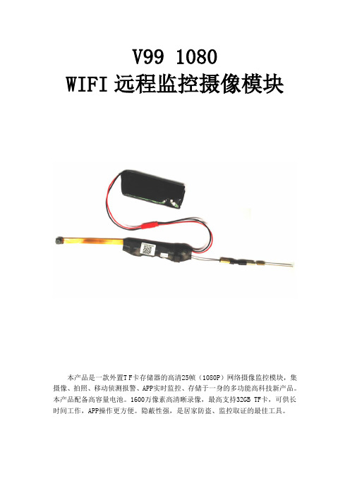
V99 1080WIFI远程监控摄像模块本产品是一款外置T F卡存储器的高清25帧(1080P)网络摄像监控模块,集摄像、拍照、移动侦测报警、APP实时监控、存储于一身的多功能高科技新产品。
本产品配备高容量电池。
1600万像素高清晰录像,最高支持32GB TF卡,可供长时间工作,APP操作更方便。
隐蔽性强,是居家防盗、监控取证的最佳工具。
前言本用户手册将快速说明如何使用本产品,同时提供给您详细的信息,包括使用、操作。
使用前请仔细阅读本手册并完全理解。
请妥善保存本手册,我们希望本产品能满足您的需求并长期服务于您!产品特点1.外观灵活,便于携带。
2.超大电池容量可长时间工作。
3.隐藏式录像功能。
4.边充边录.5.拍照、录像、录音、移动侦测报警。
6.点对点直连,无网络同样使用。
WIFI远程监控摄像模块一、产品结构二、开机(两种方式)1,接上4000mAh电池,把开关打到ON的位置开机2,连接充电线,接上电源,再把开关打到ON的位置开机WIFI远程监控摄像模块快速操作指南一.APP软件下载。
——(图1)(图2)方式1.直接扫描二维码(图1),进入下载页面(图2)。
根据手机的系统选择下载软件。
(注:此安装途径仅为中国大陆使用)方式2.安卓在Google Play 搜索名为RMON的APP软件,下载安装。
苹果在应用商店AppStore搜索名为RMON的APP软件,下载安装。
二. Wifi连接方式一。
(此连接方式适合所有家用路由器)1.手机确保连接wifi.打开设备开关。
(30秒后蓝灯闪烁,设备系统开始工作,红灯正常闪烁)2.打开下载安装好的APP软件。
(具体操作如图)步骤1(打开) 步骤2(点击) 步骤3(打开)步骤4(输入设备UID 号或扫描设备二维码)步骤5(输入已连接wifi 密码,点击)3. 当显示“WIFI 设置成功”后,点击添加“网络摄像机”。
然后等待十秒左右,返回到主菜单,会看到当前设置的设备已经在线,及WIFI 设置成功。
WiFi 内窥镜使用说明说明书
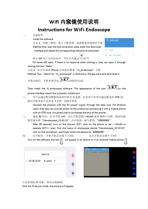
Wifi内窥镜使用说明Instructions for WiFi Endoscope一、安装软件Install the software方法1:扫描二维码,进入下载界面,选择配套系统软件下载Method One: scan the two-dimension code, enter the downloadinterface and select the corresponding software to download部分iOS用户点击没反应,可以点击通过打开For some iOS users, If there is no response when clicking it, they can open it through clicking the icon "Safari"方法2:在安卓或者iPhone应用商店搜索“XJ_endoscope”下载Method Two:Search for "XJ_endoscope" in Android or iOS app store and download it.安装完成后,手机界面多出图标即完成。
Then install the XJ_endoscope software. The appearance of the icon on the phone interface means the successful installment.二、将产品通过配送数据线连接外接5伏电源,安卓用户也可以通过配送的OTG线,通过手机来给产品供电(无图一端接手机)。
Connect the product with the 5V power supply through the data wire. For Androidusers, they also can provide power to the product by connecting it with a mobile phonewith an OTG wire. (no photo side to connected the end of the phone).三、通电30秒后,打开手机wifi,点击手机设置----WLAN或者WiFi---扫描,找到内窥镜设备名称“XJendoscope_XX:XX:XX”,点击连接,输入密码:“88888888”After 30 seconds, turn on the phone’s WiFi, click on the phone to set ----WLAN oroperate WiFi--- scan, find the name of endoscope device "XJendoscope_XX:XX:XX",click on the connection, and finally enter the password: "88888888"四、打开软件,苹果手机会出现(下图),安卓手机会出现(下图)点击里面的IP设备,即可出现画面。
ICP DAS SST-900EXT 无线无线模块用户手册说明书
Wireless Radio ModemUser’s ManualWarrantyAll products manufactured by ICP DAS are warranted against defective materials for a period of one year from the date of delivery to the original purchaser.WarningICP DAS assume no liability for damages consequent to the use of this product. ICP DAS reserves the right to change this manual at any time without notice. The information furnished by ICP DAS is believed to be accurate and reliable. However, no re-sponsibility is assumed by ICP DAS for its use, nor for any in-fringements of patents or other rights of third parties resulting from its use.CopyrightCopyright 1999 by ICP DAS. All rights are reserved. TrademarkThe names used for identification only maybe registered trademarks of their respective companies.Date:2001-11Table of Contents1. Introduction (4)1.1 Block Diagram (4)1.2 Specifications (5)1.2.1 SST-900EXT Wireless Radio Modem (5)1.2.2 SST-2400EXT Wireless Radio Modem (6)1.2.3 SST-900A External 900MHz Antenna (7)1.2.4 SST-2400A-3 External 2.4GHz Antenna (7)1.2.5 SST-2400A-12 External 2.4GHz Antenna (8)1.2.6 SST-2400A-13 External 2.4GHz Antenna (8)1.3 Pin Assignment (9)1.4 Jumper Setting (10)1.5 Wire Connection (11)1.6 Dimension (14)1.6.1 SST-900EXT and SST-2400EXT (14)1.6.2 DIN-RAIL Mounting (15)1.6.4 Pannel Mounting (16)2 Configuration (17)2.1 Full-duplex and Half-duplex (17)2.2 Synchronous and Asynchronous (18)2.3 Configuration Select (19)2.4 Operation Mode 1 (20)2.5 Operation Mode 2 (21)2.6 Operation Mode 3 (22)3 Application (23)3.1 Peer-to-Peer Communication (23)3.2 Asynchronous Connection (24)3.3 Multiple PCs Communication (25)3.4 Connect I-7000 Modules (26)3.5 Communication Bridge (27)3.6 Network Communication (28)1. IntroductionThe SST-900 and SST-2400 are radio modems that can be used in multiple access networking. The transmission method includes peer-to-peer, multi-point structure for wireless data communication. Based on direct sequence spread spectrum and RF technology operating in ISM bands, 902-928Mhz for SST-900 and 2426-2458MHz for SST-2400.1.1 Block Diagram1.2 Specifications1.2.1 SST-900EXT Wireless Radio ModemRF Communication TransceiverFrequency Band :909 to 924 MHz for SST-900Channel Spacing : 2.048 MHz (8 channels jumper select) Output Power : 20±2 dBmModulation : GMSKTime Division DuplexingTransimition Range : Max 300MSST TransceiverDirect Sequency Spread SpectrumNon-Overlapping Channels : 8 channels, jumper select (only for full-duplex operation)Full-duplex or Half-duplex, jumper selectSynchronization or Asynchronization, jumper selectSerial Communication InterfaceRS-232(TxD, RxD, GND) and RS-485(D+, D-), jumper selectBaudrate : 600bps to 57600bps, jumper selectEnvironmentOperating Temperature : 0°C to 50°CStorage Temperature : -30°C to 70°CPower SupplyInput : +10 to +30VDC, unregulatedConsumption : 1.5W1.2.2 SST-2400EXT Wireless Radio Modem RF Communication TransceiverFrequency Band : 2426 to 2458 MHzChannel Spacing : 2.048 MHz (8 channels jumper select) Output Power : 20±2 dBmModulation : GMSKTime Division DuplexingTransimition Range : Max 300M with bundled antennaMax 1000M with SST-2400A-3 antennaMax 5000M with SST-2400A-12 antennaMax 5000M with SST-2400A-13 antenna SST TransceiverDirect Sequency Spread SpectrumNon-Overlapping Channels : 8 channels, jumper select (only for full-duplex operation)Full-duplex or Half-duplex, jumper selectSynchronization or Asynchronization, jumper selectSerial Communication InterfaceRS-232(TxD, RxD, GND) and RS-485(D+, D-), jumper select Baudrate : 600bps to 57600bps, jumper selectEnvironmentOperating Temperature : 0°C to 50°CStorage Temperature : -30°C to 70°CPower SupplyInput : +10 to +30VDC, unregulatedConsumption : 1.5W1.2.3 SST-900A External 900MHz Antenna External antenna for SST-900EXTMaximum Distance : 1000MWeight : 1000gAntenna Gain : 5dBCable : RG58C/U, 4M1.2.4 SST-2400A-3 External 2.4GHz Antenna External antenna for SST-2400Maximum Distance : 1000MWeight : 150gAntenna Gain : 3dBCable : RG58A/U, 1M1.2.5 SST-2400A-12 External 2.4GHz Antenna External antenna for SST-2400Maximum Distance : 5000MWeight : 850gAntenna Gain : 12dBCable : RG58A/U, 1M1.2.6 SST-2400A-13 External 2.4GHz Antenna External antenna for SST-2400Maximum Distance : 5000MWeight : gAntenna Gain : ??dBCable : RG58A/U, 1M1.3 Pin AssignmentDSR Reserved signal of diagnosticRX Receive of RS-232TX Transimit of RS-232GND Ground of RS-232(Y)D+Data+ of RS-485(G)D-Data- of RS-485(R)+Vs+10 to +30V DC power supply input (B)GND Ground of power supply input1.4 Jumper SettingFactory default jumper setting :(1) Channel 3(2) Frequency 915.968/2439.936MHz (3) Baudrate 9600bps(4) Full-duplex(5) Slave(6) Synchronous(7) Interface RS-2321.5 Wire ConnectionWire Connection for PC’s RS-232 and SST-900/2400 : 1.The jumper(7) position inRS-232 side2.Connect SST-900/2400’sGND to CA-0910’s GND,TX to TX and RX to RX.3.Connect CA-0910’s DB-9female connector to PC’sR S-232D B-9m a l econnector.Wire Connection for I-7000 and SST-900/2400 via RS-485 1.The jumper(7) position inRS-485 side.2.D+ of SST-900/2400 to D+of RS-485 bus.3.D- of SST-900/2400 to D-of RS-485 bus.Connect SST-900EXT with SST-900AConnect SST-2400EXT with SST-2400A-3Connect SST-2400EXT with SST-2400A-12Connect SST-2400EXT with SST-2400A-13Rear View Front View Side ViewBottom ViewTop View1.6 Dimension1.6.1 SST-900EXT and SST-2400EXT1.6.2 DIN-RAIL MountingAntenna ofSST-2400EXT Antenna of SST-900EXT1.6.4 Pannel Mounting2 Configuration2.1 Full-duplex and Half-duplexFull-duplex is to transimit and receive data at the same time, and half-duplex is to transimit and receive data at seperate time. While using full-duplex mode, only peer-to-peer operation is available. For work in multi-point operation, half-duplex is the only choice.While working in full-duplex mode, one of the two com-munication modules is set as master and the other is set as slave. And both modules have same baudrate, frequency and channel select.While working in half-duplex mode, the all modules have the same configuration. The baudrate and frequency select need all the same, and all modules select slave mode. The channel se-lect is invalid for half-duplex mode. In half-duplex mode, only one module may transimit at the same time. If more than one mod-ule transimit data at the same time, the received data is not correct.2.2 Synchronous and AsynchronousIn synchronous mode is that the serial data need to specificed format, 1 start bit, 8 data bits, no parity bit and 1 stop bit.The data is readed in fixed data format and transimt. The re-ceiver receive the data and output the data in fixed data format.In asynchronous mode, the data is sampled and then transimit. And the receiver received data and regenerate the data by the sampled data. For the limitation of sampling rate of 32KHz, the data rate is limited to 14.4Kbps in order to prevent the distor-tion of the output data. While using asynchronous mode, only RS-232 interface may work.2.3 Configuration SelectThere are 3 different configuration of SST-900 and SST-2400 modules.Operation Mode 1 : Full-duplex, SynchronousPeer-to-peer communicationOne master configuration and one slave configurationMax baudrate : 19200bpsFixed data format : 1-bit start, 8-bit data, no parity, 1-bit stop Operation Mode 2 : Half-duplex, SynchronousMultiple nodescommunicationAll slave configurationMax baudrate : 57600bpsFixed data format : 1-bit start, 8-bit data, no parity, 1-bit stop Delay between transimit and receiveChannel select is disabledOperation Mode 3 : Full-duplex, AsynchronousPeer-to-peerOne master configuration and one slave configurationMax baudrate : 14400bpsV ariable data formatRS-232 interface only2.4 Operation Mode 1Operation mode 1 is full-duplex, synchronous, fixed data format communication configuration. The mode is the most com-mon mode for peer-to-peer communication. This mode may en-code the input data streams and transimit to the other SST modules. And the other modules may decode the data streams and put into serial communication line. This may decrease the communication error rate and increase the communication stability.Jumper Seeting : Refer Sec.1.4 for detail(1) : Select one channel(2) : Select one frequency(3) : Select one baudrate, max 19200 bps(4) : Full-duplex(5) : Select master or slave(6) : Synchronous(7) : RS-232 or RS-485Benefits :1.Most stable communication2.Full-duplex communicationLimitation :1.Fixed data format2.Peer-to-peer only3.Baudrates up to 19200 bpsOperation mode 2 is half-duplex, synchronous, fixed data format communication configuration. This mode may operate for communication with two or more SST modules. While operation in this mode, all SST modules are virtually connect together with an invisible line. All communication data broadcast to every SST module. The mode is suitable to build a wireless communication network with max baudrate 57600bps. For the fewer error correc-tion mechanism, the mode may have more communication error than operation mode 1.Jumper Seeting : Refer Sec.1.4 for detail(1) : Channel select is useless(2) : Select one frequency(3) : Select one baudrate(4) : Half-duplex(5) : Slave(6) : Synchronous(7) : RS-232 or RS-485Benefits :1.Multiple nodes communication2.Baudrates up to 57600 bpsLimitation :1.Fixed data format2.Half-duplex onlyOperation mode 3 is full-duplex, asynchronous commu-nication configuration. This mode is work by the way of sample and rebuild. The SST module samples the serial input (RX of RS-232) and transimit to the other SST module, and receive from RF to rebuild the serial output (TX of RS-232). For the limitation of sampling rate, the data waveform may be distorition for higher data rate.Jumper Seeting : Refer Sec.1.4 for detail(1) : Channel select is useless(2) : Select one frequency(3) : Baudrate select is useless(4) : Full-duplex(5) : Select master or slave(6) : Asynchronous(7) : RS-232Benefits :1.Full-duplex communication2.Variable data formatsLimitation :1.Peer-to-peer only2.Baudrates up to 14400 bps3.RS-232 interface only3 Application3.1 Peer-to-Peer CommunicationSST-900/2400 Configuration :Interface : RS-232Operation Mode 1 :Full-duplex Synchronous MasterBaudrate : 19200bps maxSST-900/2400 Configuration :Interface : RS-232Operation Mode 1 :Full-duplex SynchronousSlaveBaudrate : 19200bps maxNote : Basic full-duplex com-munication application for data format is 1-8-1 mode. Both SST-900/2400 modules need have same baudrateconfiguration, channel con-figuration and frequencyconfiguration.3.2 Asynchronous ConnectionSST-900/2400 Configuration :Interface : RS-232Operation Mode 3 :Full-duplex Asynchronous Master Baudrate : 9600bps max SST-900/2400 Configuration :Interface : RS-232Operation Mode 3 :Full-duplex Asynchronous Slave Baudrate : 9600bps maxNote : Asynchronous commu-nication application for data format is not 1-8-1 mode. Both SST-900/2400 modules need have same baudrate configuration, channel con-figuration and frequencyconfiguration.3.3 Multiple PCs CommunicationSST-900/2400 Configuration :Interface : RS-232Operation Mode 2 :Half-duplexSynchronousSlaveBaudrate : 57600bps max Note : Multiple PCs communi-cation application. All SST-900/2400 modules need havesame baudrate configurationand frequency configuration.3.4 Connect I-7000 ModulesSST-900/2400 Configuration :Interface : RS-232Operation Mode 1 :Full-duplex Synchronous Master Baudrate : 19200bps max SST-900/2400 Configuration :Interface : RS-485Operation Mode 1 :Full-duplex Synchronous Slave Baudrate : 19200bps maxNote : Connect I-7000 mod-ules with SST-900/2400modules. Both SST-900/2400modules need have same baudrate configuration, chan-nel configuration and fre-quency configuration.3.5 Communication BridgeSST-900/2400 Configuration : Interface : RS-232 Operation Mode 1 :Full-duplexSynchronousMasterBaudrate : 19200bps max SST-900/2400 Configuration : Interface : RS-232 Operation Mode 1 :Full-duplexSynchronousSlaveBaudrate : 19200bps maxNote : The I-7188 is an embed-ded controller with 4 serial communication ports. For dif-ferent communication proto-cols between host PC and device, the I-1788 may work as a communication bridge orprotocol converter.3.6 Network CommunicationSST-900/2400 Configuration :Interface : RS-232 or RS-485Operation Mode 2 :Half-duplexSynchronous Slave Baudrate : 57600bps max Note : Builde wireless network via SST-900/2400 and I-7188.The network is master-slave structure, and only one mastermay exist at the smae time.。
FMR1 WiFi模块加载控制器用户指南和业主手册说明书

FUNCTIONThe FMR1 Fixture Module - Relay is a high quality wire-in home automation load controller that is capable of turning 120VAC appliances and fluorescent lamps ON and OFF based on digital commands received over the power wiring from a remote UPB (Universal Powerline Bus) controller. UPB controllers and modules can be freely located anywhere throughout the home. No additional wiring is required and no radio frequency signals are used for communication. IMPORTANT SAFETY INSTRUCTIONSWhen using electrical products, basic safety precautions should always be followed, including the following:1.READ AND FOLLOW ALL SAFETY INSTRUCTIONS.2.Keep away from water. If the product comes in contactwith water or other liquid, turn off the circuit breaker and unplug the product immediately.3.Never use products that have been dropped ordamaged.4.Do not use this product outdoors.5.Do not use this product for other than its intendedpurpose.6.Do not connect multiple lamps or appliances that, whencombined, exceed the maximum load ratings of theproduct.7.To avoid any risk of fire, burns, personal injury or electricshock, install this product out of the reach of smallchildren.8.Do not cover this product with any material when in use.9.This product uses grounded plugs and sockets to reducethe risk of electric shock. These plugs and sockets fit only one way. If they do not fit, consult an electrician.10.SAVE THESE INSTRUCTIONS. INSTALLATIONThe Fixture Module – Relay is designed for indoor use with devices that are permanently wired into the home electrical system. To install the FMR1 module:1.Locate the device to be controlled. Note that the devicepower rating must not exceed 20 amps.2.Disconnect power at the circuit breaker.3.Remove any existing ceiling or wall fixture hardware for thedevice. Disconnect the black wire that supplies power tothe device.ing a wire nut, connect the black (Line) wire of thefixture module to the black (Line) power wire.ing a wire nut, connect the red (load output) wire of thefixture module to the black wire from the lighting fixture or device being controlled.ing a large wire nut, connect the white (Neutral) wire ofthe fixture module to the white (Neutral) power wire andthe white wire from the lighting fixture.7.Refer to instructions on CONFUGRATION and OPERATIONprior to placing the fixture module in its final location, as it may be necessary to have access to the Program Switch inorder to add the module to the UPB network and test itsoperation. Temporarily restore power in order to performthese functions. Disconnect power again when finished. 8.Once proper operation is established, fit the module intothe outlet box or otherwise secure it using wire ties orfitting the nipple into a ½” knockout. Reinstall fixturehardware as needed.CAUTION: Do not insert metal objects into the module while it is connected to power.FixtureCONFIGURATIONOnce your FMR1 is installed it can be configured either manually or with the UPStart Setup Software.Manual configuration can be used to add your FMR1 device into a UPB network and link it to controller buttons. Refer to the Keypad Controller’s Manual Configuration Guide available on the PulseWorx website () for more details.Although the factory default operation of the FMR1 is useful in many situations, it is highly recommended that your device be configured with UPStart Setup Software so that you can take advantage of its many configurable features.PCS has developed a Powerline Interface Module (PIM) and free UPB Setup Tool software (UPStart) to help you configure all of your PulseWorx Lighting System devices. User’s Guides are available on the PulseWorx web site: to explain how to configure your system.SETUP ModeWhen configuring a UPB system, it will be necessary to place the FMR1 in SETUP mode. To do this, press the Program Button (see illustration) five times rapidly using a non-metallic toothpick. The Status LED will continuously blink Blue when the device is in SETUP mode. To exit SETUP mode, press the Program Button once or wait five minutes for it to time out.OPERATIONThe Fixture Module operates according to commands sent by one or more UPB controllers. The FMR1 can accept powerline commands from any UPB-compatible transmitter such as PulseWorx Keypad Controllers, Timed Event Controllers, Wall Switches, Interface Modules, approved Third-Party Controllers and touch screens. The FMR1 can be a member of up to 16 scenes with the capability to store a pre-set relay state (on, off, or blink) for each scene.AUTO-OFF TimerNew for Generation 2 is the ability to set a maximum on time. If you forget to shut the fixture off yourself the fixture module will do it for you automatically. The FMR1 can be configured to inform the rest of the network when it has automatically turned the appliance off. This allows the FMR1 to remotely control other devices or update feedback indicators such as LEDs. TEST ModeA manual test feature allows the device to be turned ON and OFF locally. To enable the TEST mode press and hold the Program Button on the FMR1 for at least three seconds. The Status LED will blink Magenta to indicate TEST mode. The fixture can now be turned ON and OFF by single-tapping the Program Button. Press and hold the Program Button again for at least three seconds to exit from TEST mode.Factory Default SettingsTo restore the following default settings put the FMR1 into SETUP mode and then press the Program Button ten times rapidly. The Status LED will blink red to indicate that factory defaults have been restored. Press the Program Button twice more to stop the blinking.Network ID:255Unit ID:61Network Password:1234Receive Components:Link #1 = ONLink #2 = OFFLink #8 = Blink @ .5 sec TYPICAL USESThe FMR1 is perfect for controlling 120VAC non-dimming loads such as:•Fans,•Pumps,•Low voltage transformers,•Coffee makers,•Christmas lights.LIMITED WARRANTYSeller warrants this product, if used in accordance with all applicable instructions, to be free from original defects in materials and workmanship for a period of five years from the date of purchase. Refer to the warranty information on the PulseWorx website () for exact details.。
FTR-WT01无线视频图传模块说明书

FTR-WT01 wifi视频模块介绍惠州市方唐人科技有限公司目录1. 产品概述 (3)2. 模块参数 (5)3. 模块主要引脚说明 (6)4. 模块实物图pcba (8)5. 性能测试 (9)6. 使用方法 (10)7. FAQ (13)1.概述FTR-WT01模块是惠州方唐人科技有限公司研发的一款2.4G 150Mbps中端WIFI多媒体模块。
模块同时支持WIFI转视频、WIFI转串口、WIFI转GPIO、WIFI转I2C功能。
一般免驱USB摄像头都可以直接接入模块,进行无线视频数据采集。
视频编码方式为MJPEG,无延时手机观看视频。
特点:体积小、性能强大、数据吞吐量大。
广泛适用于图像分析、管道内窥、智能机器人等领域。
1688批发平台(量越多则价越廉):https:///offer/530160953707.html?spm=0.0.0.0.v4G14K无线wifi摄像头介绍:/v_show/id_XMTUzMTU5NDM5Ng==.html?from=y1.7-1.2Wifi摄像头在医疗内窥镜领域的应用:/v_show/id_XMTUzMTk1Njk0NA==.html2.模块参数电气参数电压 3.3V(±5%)·电流200~300mA随传输数据量变化而变化,400mA(MAX)功率0.825W ~ 1.5 W 随传输数据量变化而变化视频性能支持摄像头类型UVC标准即一般免驱USB摄像头支持视频采集格式MJPEG支持视频分辨率MJPEG 最大支持1280x720支持视频帧率1280x720 25fps640x480 60fps(由摄像头的性能决定)GPIO支持GPIO个数5个(可定制扩展至20个)控制方向输出控制状态高、低电平无线射频参数标准认证FCC/CE无线标准802.11 b/g/n,1T1R频率范围 2.412GHz-2.484GHz发射功率802.11b:+20 dBm (Max.)802.11g:+18 dBm (Max.)802.11n:+15 dBm (Max.)接收灵敏度802.11b:-89 dBm802.11g:-81 dBm802.11n:-71 dBm天线选项外置I-PEX连接器工作及保存环境条件工作温度-25℃- 85℃工作湿度10% ~ 90% RH 无凝结存储温度-40℃ - 135℃ 存储湿度5% ~ 90% RH 不凝结3. 模块主要引脚说明管脚名称 说明 1GPIO5 2GPIO1 3GPIO4 对应app 设置界面的GPIO 4NC 5GPIO3 6GPIO2 对应app 设置界面的GPIO 7I2C_SD 8I2C_SCLK 已上拉4.7k 9+3.3v 10+3.3v 3.3v 输入0.5A (max ) 给核心板供电,最好电源选大一点 11RD- 12RD+ 13TD- 14TD+ 第四组,以太网口,底板需要匹配电阻 15GND 16GND17 USB_D+Usb接口18 USB_D-19 GND20 GND21 REST_KEY 外部需上拉10k电阻,拉底5s则恢复原厂22 NC23 SYS_led24 NC25 SPI_CS126 SNAP_KEY 外部需上拉10k电阻,拉低本地拍照27 NC28 NC29 RUN_led 串口TXD30 NC31 1.8VD 1.8v输出,为外部RJ45供电32 GND33 AIFT(i2s)34 BCLK(i2s)35 AIFR(i2s)36 LRC(i2s)37 GND38 NC4.模块实物图pcba核心板(usb转wifi模块)由核心板和底板组成,底板是av转usb模块,负责将av信号转成usb给核心板,核心板负责将usb视频转成wifi视频给手机。
WiFi图传摄像定制工业WiFi内窥镜PCBA无线图传方案
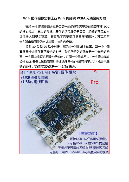
WiFi图传摄像定制工业WiFi内窥镜PCBA无线图传方案
说起wifi视频传输大家是否第一时间想到需要带有视频压缩SOC 的核心模块,庞大的系统,复杂的远程服务器等等,超额的预算成本,让很多人都望尘莫及。
其实除了需要视频需要压缩输外,其实还有wifi路由模图传的方式实现—wifi内窥镜。
很多80后和90后小时候,都玩过一种叫纸上动画。
当一个个图画连贯性快速在眼前略过的时候,我们所看到的就会是一个会动的动画。
wifi路由视频的原理也是如此,在同一个局域网内,wifi路由模块经过USB摄像头读取到图片快速地连贯性的传输到手机APP或者电脑端的时候,我们看到的就是一个视频的形态。
在小编借用BOJINGnet型号BOJINGnet_115聊聊低成本,性价比好的一款wifi内窥镜图传模块。
◆WiFi传输速率150Mbps 支持802.11b/g/n支持AP模式,有效空旷传输距离30米左右;
◆480Mbps的高速USB 2.0 Host接口,可接入USB uvc摄像头或内窥镜视频格式要求是MJPG;
◆电脑或手机可以使用VLC media player查看实时视频,或自行开发解码库app;
◆超小尺寸L53mmxW35mmxH4mm;
◆内置恢复出厂设置按键;
◆内置WiFi天线-陶瓷片式天线;
◆双Micro接口设计,供电与接摄像头设备分离;
◆支持串口数据透传,3v3 ttl接口;
◆多种应用场景:USB转WiFi内窥镜、工业USB摄像头转WiFi、USB转WiFi演讲稿制作仪、高拍仪、汽修、美容等等;。
DS-19M00-MNK 100M网络模块【用户手册】

DS-19M00-MN/K100M网络模块用户手册杭州海康威视数字技术股份有限公司技术热线:400-700-5998杭州海康威视数字技术股份有限公司| 版权所有(C )非常感谢您购买我公司的产品,如果您有什么疑问或需要请随时联系我们。
本手册适用于DS-19M00-MN/K 100M 网络模块本手册可能包含技术上不准确的地方、或与产品功能及操作不相符的地方、或印刷错误。
我公司将根据产品功能的增强而更新本手册的内容,并将定期改进或更新本手册中描述的产品或程序。
更新的内容将会在本手册的新版本中加入,恕不另行通知。
安全使用注意事项此内容的目的是确保用户正确使用本产品,以避免危险或财产损失。
在使用此产品之前,请认真阅读此说明手册并妥善保存以备日后参考。
如下所示,预防措施分为“警告”和“注意”两部分:警告:无视警告事项,可能会导致死亡或严重伤害。
注意:无视注意事项,可能会导致伤害或财产损失。
警告事项提醒用户防范潜在的死亡或严重伤害危险。
注意事项提醒用户防范潜在的伤害或财产损失危险。
警告⏹在本产品安装使用中,必须严格遵守国家和使用地区的各项电气安全规程。
⏹请使用正规厂家提供的电源适配器,供电电源要求为DC12V/1A。
⏹在接线、拆装等操作时请一定要将电源断开,切勿带电操作。
⏹如果设备工作不正常,请联系购买设备的商店或最近的服务中心,不要以任何方式拆卸或修改设备。
(对未经认可的修改或维修所导致的问题,本公司不承担责任)。
杭州海康威视数字技术股份有限公司| 版权所有(C)注意⏹请不要使物体摔落到设备上或大力震动设备,并使设备远离存在磁场干扰的地点。
避免将设备安装到表面震动或容易受到冲击的地方。
(忽视此项可能会损坏设备)⏹请不要在高温(超过75℃)或低温(低于-40℃)或高湿度地点安装设备。
⏹提供良好的通风环境。
⏹请勿在潮湿环境下操作。
⏹请勿在易爆环境中操作。
⏹保持产品表面清洁和干燥。
⏹避免接触裸露电路。
产品加电时,请勿接触裸露的接点和部件。
hac-uh480g 微功率无线数传模块用户手册说明书

HAC-uH480G微功率无线数传模块用户手册V 1.02.1 2014/05/27深圳市华奥通通信技术有限公司SHENZHEN HAC TELECOM TECHNOLOGY CO.,LTD地址 : 深圳市南山区西丽路4227号大学城创意园2栋6楼电话 : +86-755-23981078传真 : +86-755-23981007邮件:*****************************网址 : 目录1 HAC-uH480G系列微功率无线数传模块特点 (3)2 HAC-uH480G系列微功率无线数传模块的应用 (4)3 连接端子定义 (4)4 HAC-uH480G出厂默认参数 (5)5 HAC-uH480G系列微功率无线数传模块的使用方法 (5)5.1 电源 (5)5.2 功能指示灯 (6)5.3 功能设定 (6)5.3.1 接口和数据格式 (6)5.3.2 命令格式 (7)5.3.3 命令释义 (7)5.4 信道频率 (9)5.5 数据传输的注意要素 (10)5.6 支持的协议和传输容量 (11)5.7 低功耗(休眠)功能说明 (11)5.7.1 休眠功能的使用 (11)5.7.2 使用休眠功能时的注意事项 (12)5.8 外型尺寸结构示意图 (13)5.9 天线配置 (13)5.10 RESET信号使用 (15)6 HAC-uH480G系列的组网应用 (15)7 HAC-uH480G的技术指标 (16)8 型号说明 (16)1HAC-uH480G系列微功率无线数传模块特点●微功率发射,最大发射功率16dBm●ISM频段,无需申请频点。
工作频率范围470~490MHz●高抗干扰能力和低误码率基于2-GFSK的调制方式,采用高效前向纠错信道编码技术,提高了数据抗突发干扰和随机干扰的能力,在信道误码率为10-2时,可得到实际误码率10-5~10-6。
●传输距离远在开阔视距情况下,天线放置高度位置>2米,可靠传输距离可达1000m。
TYWES模块使用说明V

TYWES模块使用说明VTYWE2S模块使用说明一术语定义配网操作:加入了WiFi模块的智能化产品,使用手机App(涂鸦智能)进行的几步操作。
最终手机、路由器、WiFi模块通过2.4G WiFi无线信号彼此建立通信后,用户可以在手机App上实现对智能化产品的现场及远程的操作和控制。
详细配网操作可参见《涂鸦智能APP使用说明》WiFi模块重置:带WiFi模块的智能化产品,当路由器名称变化或者产品转赠他人时,需要清除智能化产品里WiFi模块保存的当前路由器信息,因此需要将WiFi模块重置回出厂默认状态。
可以通过手机App、物理按键等方式实现WiFi模块的重置。
此操作也称“清除WiFi 模块配网信息”。
WiFi模块状态指示灯:配网和WiFi模块重置等操作的过程中指示WiFi模块当前工作状态的指示灯。
一般会有快速闪烁、慢速闪烁、常亮、常灭等状态来清晰的告知使用者WiFi模块或者智能化产品当前的工作状态。
WiFi模块重置按键:物理的实体按键,通过特定的触发方式将WiFi模块重置。
例如长按按键5秒的方式来完成WiFi模块的重置操作。
WiFi模块自处理:WiFi模块状态指示灯和WiFi重置按键都接在智能产品里的WiFi模块上,指示灯的状态、按键的检测等操作是由WiFi模块来完成。
然后WiFi模块通过串口告知用户MCU智能产品当前的工作状态。
功能简单的产品例如插座等就不需要用户MCU,直接由WiFi模块完成全部功能。
MCU与模块混合处理:WiFi模块状态指示灯和WiFi重置按键都接在智能产品里的用户MCU上。
指示灯的状态由WiFi模块告知MCU,按键的检测是由MCU来完成,智能产品当前的工作状态由MCU通过串口与WiFi模块通信后决定。
友情提示:本应用指导说明包含多种基于TYWE2S Wifi模块设计的智能产品Demo,例如智能独立插座、智能多路开关,智能排插等。
用户可根据自身需求及产品类型选择相应章节查看。
如产品是基于TYWE2S模块与用户MCU对接来完成,那么硬件设计时需要重点关注第二章《与MCU 通信连接说明》。
MOD103-PT 图传模块手册说明书
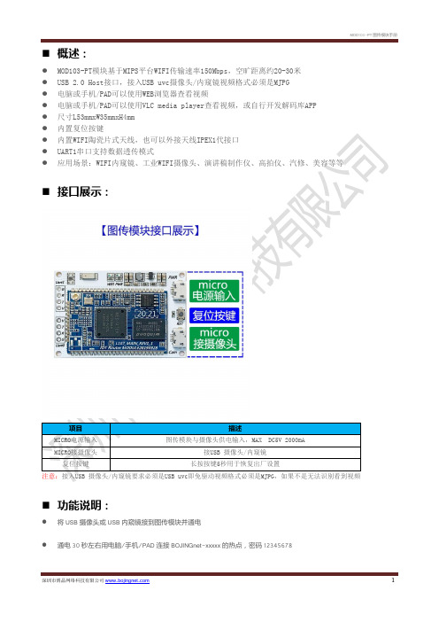
⏹概述:
●MOD103-PT模块基于MIPS平台WIFI传输速率150Mbps,空旷距离约20-30米
●USB 2.0 Host接口,接入USB uvc摄像头/内窥镜视频格式必须是MJPG
●电脑或手机/PAD可以使用WEB浏览器查看视频
●电脑或手机/PAD可以使用VLC media player查看视频,或自行开发解码库APP ●尺寸L53mmxW35mmxH4mm
项目描述
⏹功能说明:
●将USB摄像头或USB内窥镜接到图传模块并通电
●通电30秒左右用电脑/手机/PAD连接BOJINGnet-xxxxx的热点,密码12345678
●电脑/手机/PAD连接成功后打开谷歌浏览器在地址栏输入10.10.10.1:8080如下图
●Enter键确定即可看到图像如下图(注意:如果浏览器无内置解码库可能无法查看视频具体以实际测试为准,如果是电
脑推荐使用谷歌原生浏览器,IOS设备推荐使用Safari浏览器,安卓设备推荐使用谷歌原生浏览器,如浏览器都无法查看视频可以使用VLC media player播放器查看具体参考后页有介绍)
●用VLC media player查看视频方法
●电脑/手机/PAD上安装VLC media player播放器并打开
●点击媒体选项卡
●点击打开网络串流并输入http://10.10.10.1:8080
●点击播放即可看到视频(注意:VLC播放器解码视频是使用缓存方式解码所以图像会有延时属于正常现象)。
新内窥镜说明书

一. 【内窥镜影像工作站】结构及参数视频参数:设臵密码hlsoft1.结构:2.基本参数:二. 【内窥镜影像工作站】软件特点与国内同类产品相比具有以下特点1、图像实时显示清晰的图像实时显示,方便教学及多人观察、会诊。
2、动态图片库提供一个病员的动态图片库,操作该图片库的方法只需设定图像范围,点击抓取图像按钮即可。
同时该图片库随新建病员资料而清空。
3、按钮化操作工作站采用按钮操作,医生在使用时无需一级一级选取菜单上的命令,只要点击工具框上的按钮就可完成所需操作。
4、动态跟踪提示工作站操作具有动态跟踪提示功能,如果是首次操作或是忘掉图标按钮的功能,只需将鼠标指针在按钮上停留半秒,便可在鼠标下方得到动态跟踪提示。
5、直观的伪彩编码显示,方便的加彩按钮工作站提供的八套伪彩编码直接显示在图像处理框中,无需记住各种伪彩结果,各种编码形成明显的对比。
当需要对病灶区进行伪彩处理时,只需用鼠标按下图像处理框中的加彩处理按钮便可实现图像加彩。
6、可视化图像处理具有真正所见即所得的可视化图像处理功能,并可及时观察处理结果,确定后,系统程序自动将选定区域处理结果保存。
7、取消处理如对处理后的图像不满意,可以按取消按钮,取消图像处理。
8、图像标注工作站设有图像标注功能,可以在图像上标注文字信息。
9、打印预览工作站提供打印预览功能,在打印之前先进行预览,检查其中的错误,提高打印的正确率节省不必要的浪费。
10、多种打印模式可选工作站提供多种打印模式供选择,并根据用户要求,单独开发用户要求模式。
11、系统直接启动工作站可在进入Windows操作系统后直接运行其程序,结束操作时,根据需要直接关闭计算机或退出本系统。
操作者无需学习Windows的使用方法,真正将计算机作为仪器,使计算机运行“傻瓜化”。
12、历史病历查询及统计通过简单的操作方法即可对以前做过的病员信息进行查询及统计,方便医院进行考核及评估。
13、院部设臵为了医师的操作更加方便、快捷,医院的基础信息可预先设臵并自动加载。
2012-7-赛远工业无线传输模块SY-WT6用户手册-V1.9

工业无线通讯模块 SY-WT6 用户手册
深圳市赛远自动化系统有限公司
Shenzhen Futurelooks Automation System Co.,Ltd
深圳市赛远自动化系统有限公司
Shenzhen Futurelooks Automation System Co.,Ltd. 服务热线 Hotline:400-066-5616 企业 QQ:400-066-5616 E-mail: tech@
欢迎使用获得国家专利(专利号为:ZL 200920261853.5)的赛远SY-WT6系列工业无
线通讯模块,使用前请仔细阅读该说明。
赛远,创新的技术,出众的品质,为广大客户提供优质的服务。
客户服务热线:
400-066-5616
企业QQ:
400-066-5616
专利:ZL 200920261853.5
微控制器
射频开关
射频功率放大器
双VCO
双频率合成器
射频接收放大器
混频/检波
MODEM
Hale Waihona Puke 要传输的数据SY-WT6 系列无线通讯模块方框图 SY-WT6 系列无线通讯模块在使用中,频率设置工作由模块内的微控制器来处理,加电 后模块先处于接收状态,天线接收的射频信号经放大,混频,检波后,送入调制解调器 MODEM,由 MODEM 还原出发射端发出的数字信号。当需要进行发射时,数字信号先进入 MODEM,由 MODEM 产生相应的移频键控 FSK 或最小频移键控 MSK 信号,去调制发射 压控振荡器(VCO)并产生所需的射频信号,经射频功放由天线发射出去。 SY-WT6 系列无线通讯模块采用双 VCO 来分别产生用于接收和发射的射频信号,可实 现接收和发射之间的快速转换。
IC-5150W全景式鱼眼无线网络摄像头用户指南说明书

IC-5150W全景式魚眼無線網路攝影機包裝內容IC-5050W 安裝指南CD 電源變壓器網路線壁掛架螺絲與壁虎LED指示燈硬體安裝請您按照本章節的說明,使用Wi-Fi無線網路連線,安裝並啟動EdiLife手機APP 來設定您的IC-5150W,您也可以使用電腦,以有線網路連接的方式來設定(詳情請參閱CD內附使用手冊)。
您可以在本產品底座標籤貼紙上找到產品獨有的SSID,它會是如此標示"EdiView.Setup** " ,而最後兩碼** 即為您的網路攝影機獨有的MAC 位址的最後兩碼。
1.請將包裝內附的電源變壓器連接至產品本體底部的電源連接埠,並將插頭端插入電源插座。
2.請稍待本產品開機完成。
當產品本體的電源LED燈號呈現綠燈慢速閃爍的狀態,代表已開機完成。
3.請使用您的手機或平板,依您其作業系統至Google Play或Apple AppStore搜尋〝EdiLife〞APP,然後下載並安裝。
4.iOS用戶請在啟動EdiLife之前,先前往您iPhone的Wi-Fi設定,並連接到您網路攝影機的SSID (EdiView.Setup **),接著請前往步驟7。
5.Android用戶請啟動EdiLife後,點擊視窗畫面右上方的+圖示(如下右圖示)。
6.Android用戶請自可用的無線裝置清單中選擇您的無線網路攝影機後,耐心稍待APP建立連線。
若您未看到您想要連線的無線網路攝影機,請點擊右上角的”重新整理” 圖示。
7.當您看到如下提示對話框,為了安全考量,請輸入新的裝置名稱和密碼。
接著,請點選Done(確認)以繼續。
(密碼至少8碼)8.請從清單中選擇您的Wi-Fi無線網路,然後輸入您的Wi-Fi無線網路密碼後,再按OK "確定"。
若您未看到您想要連線的Wi-Fi無線網路,請點擊右上角的”重新整理” 圖示。
9.請稍候您的IC-5150W連接到您的無線網路。
當你看到"Setupcomplete(完成安裝)"畫面時,請按下"Live"圖示以繼續,或等待數秒自動繼續。
内窥镜使用说明书(v4.6)

目录第一部分:内窥镜工作站的运行环境,特点及安装方法一、内窥镜工作站软件的运行境 (3)二、软件的特点 (3)三、软件安装方法 (5)四、软件运行 (5)第二部分:软件功能按钮介绍与教程一.软件主窗口 (6)二、程序操作区各按钮功能1、建新病历 (6)2、保存病历 (6)3、采集图片 (6)4、图像处理窗口 (7)5、冻结 (9)6、生成报告 (9)7、系统设置 (12)7-1、报告格式设置 (12)7-2、报告格式编辑窗口 (13)7-3、伪彩设置 (17)7-4、系统设置 (18)7-5、术语设置 (19)8、病历管理窗口 (20)8-1、备份功能 (21)8-2、查询功能区 (22)8-3、排序功能区 (23)8-4、设置功能区 (24)8-5、病历操作控制区 (25)2-8-1、打开病历 (25)2-8-2、删除病历 (25)2-8-3、工作量统计 (25)9、退出系统 (26)10、诊断图库 (26)11、视频动态回放功能区 (27)12、亮度、对比度和饱和度调整 (28)13、全屏显示 (28)三、病人主要信息输入区功能窗口 (28)1、选择内容设置窗口 (28)第一部分内窥镜工作站的运行环境、特点及安装方法一.软件的运行环境.Microsoft Windows98/2000/XP操作系统.MMX奔腾II级PC;32MB以上内存.3000MB可用硬盘空间.支持24-bit(真彩色),显示器分辨率为1024*768.支持直接写屏显卡.CD-ROM驱动器.医疗专用视频采集卡.720dpi分辨率以上的彩色喷墨打印机二.软件的特点我们在开发过程中从用户使用的角度出发,设计了方便简精的界面风格,多功能全方位的实时编辑,安全可靠的运行环境,使您的操作倍感流畅、轻松、快捷!以下是本软件的部分特点:■方便快捷的病历内容输入在填写病历资料时,很多内容相对固定,变化不大。
对于检查所见和诊断结果,我们为您内置了比较常用的模板,您只需根据提示选择即可。
3R-PPMC-S 内窥镜使用说明书

使用说明书Counseling▪Microscope型号:3R-PPMC-S为了确保安全,使用前请务必阅读本说明书!声明因编辑时间有限,不保证本说明书中没有错误。
本说明书作为产品系列说明书,因为配置的不同,产品功能也不同,具体功能配置请以购买时的技术要求为准。
技术规格会随时更改,恕不通知。
目录用前须知 (2)主要配置 (2)按键及接口 (3)用途和适用范围 (4)售后维护 (5)使用安全 (5)1产品简介 (6)1.1产品技术参数 (6)2使用步骤 (7)2.1产品取出 (7)2.2使用前检查 (8)2.3开始检测工作 (9)2.4探头弯曲操控 (9)2.5完成使用 (10)3捕捉图像及操作 (11)3.1拍照/录像 (11)3.2查看图像 (11)3.3LED亮度调节 (11)3.4图像缩放 (11)3.5连接电脑 (12)3.6功能设置 (13)4故障排除 (14)用前须知主要配置防水、防摔仪器箱Micro USB/HDMI数据线主机TF卡读卡器本配置主要是为了展示给用户查阅,具体配置请以装箱清单为准!按键及接口⑵确认按键⑸回看按键⑷亮度调节按键⑶标尺开关键⑴菜单按键(7)放大按键⑿复位孔⒃Micro USB 口(8)上翻按键⒁HDMI 视频输出⒂TF 卡槽⑼下翻按键(6)返回按键⑾拍照/录像按键⑽WIFI 开关按键⒀开关机按键⒄Micro USB 充电口电量指示灯工作指示灯(1)菜单按键:功能设置,主要有图像设置、戳记、语言设置、时间设置、版本号等;(2)确认按键:在菜单设置中,这个按键作为确认功能;(3)标尺开关键:在预览状态中,长按此键,可以开关虚拟标尺功能(4)亮度调节按键:用于调节内窥镜的光源的亮度等级,从0~9循环使用;(5)回看按键:在预览状态中,按下回看按键,直接跳转到照片/视频查看页面;(6)返回按键:用于各种状态下,返回上一级的功能;(7)放大按键:在预览状态中,按2秒“回看按键”,进入缩放模式。
施罗德管道潜望镜中文界面说明书

目录一、安全事项 (2)二、产品、环境及安全标示符号 (3)三、产品介绍 (7)1、主要应用领域 (7)2、功能特点 (7)3、系统组成 (11)四、操作流程说明 (41)1、产品连接步骤 (41)2、现场检测 (47)五、日常维护保养及注意事项 (48)六、配置清单(标配型) (49)七、故障诊断 (50)八、保证 (51)九、产品保修 (52)使用说明书一、安全事项中提供了有关安全事项的更详细信息。
1、严禁将设备置于超过10米水深的环境场所检测。
2、严禁带电状态下进行设备连接,连接时应确认掌握正确的连接方法。
3、严禁在有高浓度危险气体的环境下工作,必须排险后方可投放设备。
4、严禁在设备工作状态下进行充气。
5、严禁设备带故障操作,设备作业时,气压值异常,必须立即将设备回收,检查故障。
6、严禁粗暴作业,设备安装调试时,必须严格按照操作规范和正确步骤进行。
7、必须使用经认可的配件和电池。
请勿连接不兼容的产品。
8、严禁私自拆卸设备,发现故障应立即通知厂家客服部,由专门技术人员进行检修。
未经许可的任何拆卸和私自改动,都将导致设备保修条款失效二、 产品、环境及安全标示符号充电器防止下雨淋湿,适合室内使用;使用前,尽量远离孩子们玩耍的地方,同时确保充电器与产品电池是否配套,当电池充满电时,请及时拔除插头,以免烧坏充电器。
潜望镜机头充气气压范围4.5~12.5PSI ;严禁在危险场所使用,以免发生爆炸;非专业人士禁止拆开后盖。
插拔8芯航空公头时,切勿左右旋转,避免8芯航空公头或母头损坏,接触不良等。
5.7寸控制器内置聚合物电池,电量不足充电时注意不要过充或者过放,过充或者过放都会使电池内部化学物质的可逆性遭到破坏,甚至引起短路,从而严重影响电池的寿命。
为避免机器漏电、短路现象,充电或者闲置时,请放置干燥通风处。
警示: 警示: 警示: 警示:表示运输包装件怕压,正确位置是竖直向上,里面有不可放倒的物品或者设备。
NIDAGE Wifi 内窥镜摄像头 用户手册

1. Search the free “HDWifi” APP in Apple Store or Google Play Store.2. Turn on the endoscope WiFi box power switch fistly.the blue power LED and the blue signal LED will light up.3. Connect endoscope to smart phone(1) Turn on your smart phone,then click the “Setting” icon on the main menu of smart phone. (2) Choose Wlan/Wi-Fi to select and connect the default WiFi from the endoscope “NIDAGE_*****” by entering default password “12345678”and then click “join” to connect. (3) When connection is done ,the blue WiFi singal light will flick,if not,that means it fails in connection. if failure,please reconnect or check the power of WiFi box is enough or not. (if the battery is not enough in power , please charge WiFi box through DC5V 1A adapter (4) After joining the endoscope WiFi,please click the free “HD WiFi” App on your smart devices and then you are ready to operate the camera. Download And Install Detailed Operation Steps:HDWiFi Modify SSID name and password 1. Click “Setting” icon in “HD WiFi” App,and input t password you want to set.2 Then click “Set WiFi SSID” or “ Set Password” to finish to modification.Setting: to set SSID name ,WiFi password, resolutionPicture Capture: snapshot in-time picture Video Record: to record video by press this button Album: to browse the captured pictures and recorded videoPicture Rotate: to rotate in-time picture Capture Photo,Record Video,Browse Photo And Video 1.Click icon for photo capturing 2.Click icon to start video recording till the time that you want to stoprecording by clicking icon again.3. Click icon to browser captured photos or recorded videos.(Note: the photos and videos will be saved in your photo app when you enable the app accesible to the “photo” in your photo setting.Photo Video How To Install Accessories Anticlockwise Rotate Clockwise Rotate The thre(3) included accessaries(mirror,hook and magnet) are all atached to the camera in the same way as illustrated below LED Brightness Adjust Product Struction Production125MM。
