现浇连续梁MSS滑移模架的施工工法(工法)
桥梁施工工法之Mss移动模架
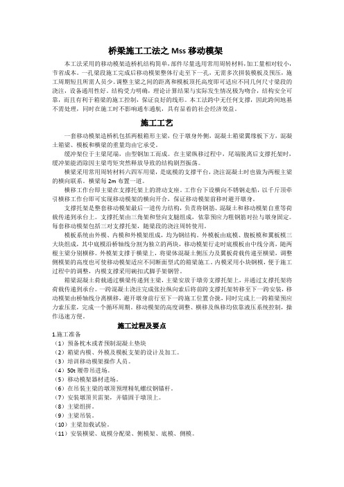
桥梁施工工法之Mss移动模架本工法采用的移动模架造桥机结构简单,部件尽量选用常用周转材料,加工量相对较小,节省成本。
一孔梁段施工完成后移动模架整体行走至下一孔,无需多次拼装模板及预压,施工周期短且所需人员少。
调整主梁之间的距离和模板顶托高度即可适应不同几何尺寸梁段的浇注,设备通用性好。
结构受力明确,理论计算结果与实际发生情况极为吻合,结构安全可靠,而且有利于箱梁的施工控制,保证良好的线形。
本工法跨中无任何支撑,因此跨间地基不需处理,同时在施工时不影响通车通航,具有显着的社会经济效益。
施工工艺一套移动模架造桥机包括两根箱形主梁,位于墩身外侧,混凝土箱梁翼缘板下方,混凝土箱梁、模板和横梁的重量均由它承受。
缓冲架位于主梁尾端,由型钢加工而成。
在主梁纵移过程中,尾端脱离后支撑托架时,缓冲架能消除因主梁弯矩突然释放导致的结构剧烈振荡。
横梁采用常用周转材料六四军用梁,是底模的支撑平台,浇注混凝土时也做为两根主梁的横向联系。
横梁每2m布置一道。
横移工作台即主梁在支撑托架上的滑动支座。
工作台下设横向不锈钢走船,以千斤顶牵引横移工作台即可实现移动模架的横向开合,保证移动模架前移时避开墩身。
支撑托架是整套移动模架最后一道传力结构,负责将钢筋、混凝土和移动模架自重等荷载传递到承台上。
支撑托架由三角架和竖向支腿组成,依靠预应力粗钢筋对拉与墩身固定。
每套移动模架包括三对支撑托架,随梁段的浇注周转使用。
模板系统由外模、内模和外模架组成,均为钢结构。
外模板由底模、腹板模和翼板模三大块组成,其中底模沿桥轴线分割为独立的两块,移动模架行走时底模板由中线分离,随两根主梁分别横移。
外模架支撑于横梁上,将梁体混凝土侧压力及翼板荷载传递至横梁,调整侧模架的高度也可使移动模架适应不同断面型式的箱梁施工。
内模采用小块钢模,便于施工过程中的调整,内模支撑采用碗扣式脚手架钢管。
箱梁混凝土荷载通过横梁传递到主梁,主梁安放于墩旁支撑托架上,并通过支撑托架将荷载传递到承台。
MSS滑移模架施工工艺及技术控制-10页精选文档
MSS滑移模架施工工艺及技术控制Proceedings of the fourteenth annual meeting of the society of bridge and structural engineering, Chinese society of Civil EngineeringChinese Institute of civil engineering of bridge and structural engineering institute proceedings of the fourteenth annual conference of the Nanjing Yangtze River Bridge project. Construction technology and technical control of MSS sliding die setNanjing Yangtze River Bridge 50m bridge constructionLiu Jizheng, Qi Lujie, Wang Xiaoshan(Shandong Province Traffic Engineering Corporation, Nanjing Yangtze River Bridge Project Department)[Abstract] this paper briefly introduces the structure and composition of MSS slip and its application in construction. Sliding formwork; construction technology; deflection control I. General Situation of the projectNanjing Yangtze River Bridge North Bridge bridge upper structure for 16m*30m and 5m*50m PC with variable cross section continuous beam bridge. The whole bridge section is composed of two single box and single chamber beam sections separated from top to bottom, and a central partition cover plate is arranged in the middle. among5 * 50m approach bridge in30m approach bridge and the main bridge transition section, the bridge is located in land and water, land a hole, four holes on the water, the peak water level 7m. Therefore, it is very important to choose an optimum construction scheme.Two, scheme comparisonBased on the bridge position of 50m bridge, two schemes should be adopted for the construction of superstructure: 1. Supportconstruction, set up a full support with one hole on the river bank, insert four hole copper pipe pile in water, and build a steel pipe pile support. Adopt the construction without scaffold. That is, the introduction of foreign advanced equipment - sliding die frame for construction.The first construction plan is the traditional construction method of our company. There are abundant construction experience, the technology is easy to control, but this scheme for water construction, heavy workload, Jixietaiban, the economy is not reasonable, the construction schedule is not ideal. Second kinds of construction schemes, advanced construction equipment, with the leading domestic level, but this kind of equipment is used for the first time our company, the technology is difficult to control, for the construction of water in the middle span cast-in-place continuous beam bridge is particularly suitable for. Synthetic manifold reasonsIn consideration of Nanjing bridge project of the company ultimately decided to use no scaffolding construction that the introduction of MSS sliding formwork system.Three, sliding mode profilesThe MSS slide beam introduced by our company is mainly composed of six parts, the bracket (Niu Tui), the main beam (Gang Xiangliang), the crossbeam, the back beam, the external die and the internal die. Each part is equipped with an internal hydraulic or mechanical system. The structure and function of each component are as follows:1. bracketBrackets are commonly called brackets and triangular structures. Through the reserved hole (diameter: 80cm*100cm) insert attached to the pier on the pier. Its role is to supportthe main girder, the main girder load transfer to the pier on the bracket. A sliding block is arranged on the top face of each bracket. It is equipped with two pairs of 20t horizontal automatic moving hydraulic jacks.A 450t vertical automatic hydraulic jack, a longitudinal moving hydraulic jack. The main beam is embedded in the overhead travelling crane. In order to reduce the friction between the main beam and the crown when moving in longitudinal direction, the crane is equipped with a poly four vinyl slide board, and the main beam is positioned in the direction of the slab, the direction of the bridge and the vertical height through the three hydraulic system.2. main beamThe sliding girder is a pair of steel box girders. The section size of the steel box girder is wide: 2.0m, height: 3.0m, length 64.8m, divided into six sections - 10.7m + 4*0.8m+10.9m). The joints are connected by friction type high strength bolts. In order to make the main beam slide along the bridge from the upper hole to the next hole, the front and back of the main beam is equipped with a bridge type nose bridge, long 21m. The main girder is a load bearing component of the sliding mode, weighing about 350t. The main beam is provided with a window, and the crossbeam is provided with a main beam; a vertical hydraulic jack, a mechanical jack and a horizontal jack are arranged in the window. The steel beam is hinged with the main beam through the pressure system, and the main beam is subjected to the construction load of the external, internal and upper structure transferred by the crossbeam.3. beamThe whole sliding mode has 18 pairs of cross beams, the beam is "H" type, the steel structure size is 35cm*90cm*900cm, eachpair of beams for pin connection, the beam spacing 3.6m, the beam has no pin hole, in order to install the external mold support. The cross beam can be adjusted vertically and transversely through the pressure system in the main beam. 4. external dieThe outer mold comprises a bottom plate, web plate, rib and flange component. The floor plate is directly laid between the two adjacent transverse beams and corresponds with the crossbeam. The connecting direction of each pair of bottom plates along the direction of the cross beam is connected by common bolts. The outer template joint is in the outer mould central axis. Total floor width 6.5m. The web, rib and flange also corresponds with the beam, and through the template bracket and the supporting beams are provided to install. 5. internal modelSet along the internal mold mold shifting system including the template, electric car, rail and beam model. The transverse transportation and installation of electric car to complete the. The electric car is equipped with a hydraulic system, through which the hydraulic system to complete the installation of internal die.Four 、 construction principle and process flow of Slipform The installation and adjustment of slip and slip mold MSS template is "hydraulic" as the driving force to the hydraulic jack to work in control equipment, hydraulic control device, the hydraulic jack push, thus completing the adjustment in place, the cross beam and the inner and outer mould installation and adjustment. Before construction, first of all, the preparation of the construction along the technical program. The purchase of special equipment, machinery and equipment, leasing large lifting equipment. Sliding mode constructionaccording to the following procedures: (Niu Tui) bracket assembly, girder assembling and related construction design tools in place, lifting bracket girder hoisting and installation, beam main beam in place, laying floor, installation of formwork support, installation and construction of the outer web and flange plate, plate, die. Five, slip form site specific assemblyThe quality of field assembly of slip form directly affects the quality, schedule and construction safety of box girder construction. Therefore, when assembling,According to the design drawings along the die, in strict accordance with the "steel construction technical specifications" for operation, for high-strength bolt joint surface, careful inspection, one by one surface treatment, so as to achieve the proper coefficient of friction. High strength bolt connection, take the initial and final material express, repeated operation, make every bolt meet the design of torque wrench torque value, and periodic calibration, ensure the connecting force strength, preventing engineering accidents, affecting the quality of construction safety and construction (with) parts must be removed or treated qualified rear can use. Bracket assembly on site: because the bracket is triangular and has a certain height, the site assembly is unstable and should be supported by a triangular support. The lifting bracket placement, pier reserved hole, with the top bracket by leveling leveling, so that the crane on the surface smooth slip. In order to prevent the carriage capsized in the force, each of the bracket is composed of thread to pull, embedded pier, so the installation bracket should be on the other side of unilateral temporary placement of a carrying pole, wear thread tension, to prevent instability.The main beam is installed; because the main girder is self important, the whole hoisting is difficult. During construction, the crane is hoisted at two times, and temporary support is arranged in the span to carry out the closure assembly. This requires the temporary support of the elevation of accurate measurement and slope, so that the steel beam in the middle of the smooth docking, assembly.After the main girder is assembled, the crossbeam is placed at the main beam window, and the main beam is placed under the influence of the hydraulic system, and the bridge is positioned accurately in the direction of the hydraulic system when all the beams are installed. A total station or theodolite is installed at the center of the pier, the bridge axis is released, the crossbeam is adjusted according to the axis of the bridge, and the bottom plate is laid with a pin, and the axis deviation is controlled within 5mm. Then, the installation of the web and flange plates.When assembling the slip form, the parts are required to be connected reliably. After assembly, the utility model can be safely and reliably checked, and can be used for the construction of the upper structure.Six 、 adjustment of template and elevation controlIn order to better set camber, this set of sliding formwork is designed with LCM formwork, and the design is supported by sheet iron. According to the actual construction practice, taking into account the quality of the cast beam body, we adopted the putty to add the curing agent to adjust the caulking and smoothing. As a kind of better mending joint material, it has good curing speed and high strength. It meets the requirement of construction specification. The quality of the cast beam is better.Elevation control: it is difficult for the construction of the sliding mode to reserve a certain degree of arch so that the beam can reach its design elevation as much as possible. Therefore, the source of the deflection value of the construction frame should be considered comprehensively; the theoretical calculation of deflection value should be accurate. The source of this set of sliding mode deflections has the following four aspects:(L) deflection value of concrete self weight (value supplied by manufacturer VCE company);(2) the deflection caused by the cantilever boom (without considering the weight of the sliding form) is calculated according to the 13mm (according to the triangle distribution) and adjusted accordingly when measured;(3) prestressed tensioning the camber, between the front and rear pivot part according to parabola distribution, parabolic center maximum deflection according to 20mm, the maximum cantilever deflection according to 13mm (according to triangle);(4) the deflection caused by the settlement of the bracket is calculated according to 10mm.Through observation, deflection deflection calculation and the actual construction process of the accord, but slightly different, so in the construction of a hole, careful observation of each construction stage, measuring the deflection value changes, but compared with the theoretical calculation, so as to guide the construction of the next hole; reduces the construction error, guarantee the construction of the girder elevation and the design elevation deviation is reduced to less than 1cm.Seven, the construction process of box girderThe 50m approach box girder adopts equal section beam, the beam height is 2.6m, the box girder roof thickness is constant, the web and floor thickness change, the bridge width is 32m, and the upper and lower separate single box single chamber section, the straight bridge. Box girder construction from the beginning of the shore, each construction at the next gap in the gap 8m (L / 6 near) continuous construction, construction process flow chart shown in figure 1.Because the construction operation is cyclical, in order to improve work efficiency and speed up the construction process, each process should be compact and connected. At the same time, the preparation of the next process is effectively shortened, and the construction period is shortened.During the construction, the first pouring hole, the template before and after the pivot in before and after the piers, and other casting hole. In order to ensure the smooth construction joint, located in front of the pier top pivot, after the pivot on the cantilever end has been pouring completed, the rear suspension rod lifting beam main beam, as a support.The pouring of concrete adopts one casting construction method, and the two step is carried out. Pour the bottom and the web first and then pour the roof. And start from the end of the cantilever to prevent excessive deflection deformation of the main beam span.In the end of construction need to move across, first sliding off the rack, demoulding, lift the connection beam according to pin horizontal slip, outside, avoid the pier, then the longitudinal slip to the next hole. The main beam with a connecting rod, a crossbeam and a template is unstable when moving; in order to achieve balance, the concrete counterweight is arranged outside the main beam.Eight, concluding remarksThe construction of the project adopts the sliding formwork method, with a high degree of mechanization. The complete process such as formwork, steel bar, concrete and tensioning technology can be completed in the mold base. At the same time as the construction work period, and not subject to the interference of external factors, not only for the project management, but also can improve the quality of the project, to speed up the construction schedule, shorten the construction period, the construction period is the fastest single hole with only 12 days to complete. And it is crucial to complete the construction of 50m approach bridge before the closure of the main bridge.The movable scaffolding system requires a set of equipment and accessories, in addition to a considerable amount of steel, it needs a set of mechanical power equipment and automatic device, a large investment, in order to improve the efficiency, must solve the assembly and scientific management problems.The construction of 50m approach bridge adopts this set of moving formwork, which solves these two problems. The main components along the die are assembled, which can be used in bridges of different spans, different bridge widths and different shapes, so as to enlarge the service surface and reduce the construction cost. In the construction of the professional construction team, organization of scientific management, the fixed operation, do use equipments, and pay attention to maintenance and maintenance equipment, give full play to the ability to use the equipment, and achieved good economic benefits.Reference[l] Ministry of communications, First Highway EngineeringBureau. Highway Construction Manual (bridge and culvert). Beijing: people Communications Press, 1985[2] fan Lichu. Prestressed concrete continuous girder bridge. Beijing: China Communications Press, 1985.1。
移动模架施工工艺工法
移动模架施工工艺工法(QB/ZTYJGYGF-QL-0503-2011)桥梁工程有限公司赵红来刘涛1 前言1.1 工艺工法概况移动模架系统(move support system)简称MSS,是桥梁施工的先进方法。
移动模架系统是一种自带模板,利用承重梁支承模板,对混凝土梁进行逐孔现场浇注的施工机械。
国外,最早在1969年由德国PZ公司研制在德国阿母辛克(Amsinck)桥正式使用。
国内最早于1990年引进该类造桥设备施工了厦门高集海峡公路大桥。
移动模架承重部分类型常见的多为两组定型的钢箱主梁(图1),也有使用拆装式常备杆件改造后的桁梁(图2);定型钢箱主梁形式的移动模架系统一般为专门设计,对匹配梁型使用,梁跨20~60m范围均有应用;拆装式常备杆件形式的移动模架系统的优势在于平曲线半径较小、梁跨多种组合等定型移动模架无法适应的环境下,钢箱主梁式移动模架与桁架主梁式移动模架原理基本相同,本工法主要内容为桁架主梁式移动模架。
图1 钢箱主梁式移动模架构造图钢箱主梁式移动模架结构系统主要有:钢箱主梁、桁式鼻梁、横梁、模板系统、平台支架系统、支承移动模架主梁的支承系统、移动模架前移及横梁模板开合调整的液压控制系统。
图2 桁架主梁式移动模架构造图该类移动模架体系由四部分组成:①固定于桥墩上部用来支承桁梁平台的支承体系;②收折式桁梁平台;③平台转跨推进行走系统;④支架平台上的满堂支架体系。
1.2 工艺原理1.2.1 整个支撑体系附着于支撑墩柱或支承于桥梁承台上,通过支撑键及预埋键盒,将施工荷载全部转移至墩柱或承台之上,不再设置临时支墩。
1.2.2 每组桁梁通过可收折横联形成整体,作为现浇梁施工的支架平台。
1.2.3 支撑体系上设置横、纵及竖向移动装置,完成横移、纵移及高度调整。
2 工艺工法特点2.1 无需地基处理,能对高度较大、无法或较难设置落地支架的现浇梁进行施工,减少了对环境的依赖和破坏,适用范围广。
2.2 使用常备杆件,可依具体施工条件进行组合,适应性强。
移动模架施工工艺工法

移动模架施工工艺工法1 前言1.1 概况移动模架系统(move support system)简称MSS,是桥梁施工的先进方法。
移动模架系统是一种自带模板,利用承重梁支承模板,对混凝土梁进行逐孔现场浇注的施工机械。
国外,最早在1969年由德国PZ公司研制在德国阿母辛克(Amsinck)桥正式使用。
国内最早于1990年引进该类造桥设备施工了厦门高集海峡公路大桥。
移动模架承重部分类型常见的多为两组定型的钢箱主梁(图1),也有使用拆装式常备杆件改造后的桁梁(图2);定型钢箱主梁形式的移动模架系统一般为专门设计,对匹配梁型使用,梁跨20~40m范围均有应用;拆装式常备杆件形式的移动模架系统的优势在于平曲线半径较小、梁跨多种组合等定型移动模架无法适应的环境下,本工法主要内容为后者。
图1 钢箱主梁式移动模架构造图图2 桁架主梁式移动模架构造图该类移动模架体系由四部分组成:①固定于桥墩上部用来支承桁梁平台的支承体系;②收折式桁梁平台;③平台转跨推进行走系统;④支架平台上的满堂支架体系。
1.2 工艺原理1.2.1 整个支撑体系附着于支撑墩柱上,通过支撑键及预埋键盒,将施工荷载全部转移至墩柱之上,不再设置临时支墩。
1.2.2 每组桁梁通过可收折横联行成整体,作为现浇梁施工的支架平台。
1.2.3 支撑体系上设置横、纵移装置,完成横移及纵移。
2 工艺工法特点2.1 无需地基处理,能对高度较大、无法或较难设置落地支架的现浇梁进行施工,减少了对环境的依赖和破坏,适用范围广。
2.2 使用常备杆件,可依具体施工条件进行组合,适应性强。
牵引设备移动,操作简单,安全可靠。
2.3 采用倒三角及倒梯形加强承重杆系,为桁梁提供足够的抗弯能力及刚度;承重杆系为收折设计,满足平台向前行走。
2.4 标准化作业、施工周期快、质量好。
3 适用范围3.1 高墩现浇箱梁施工。
3.2 复杂地形现浇梁施工。
3.3 水上多跨现浇梁施工。
4 主要技术标准《铁路架桥机架梁规程》TB10213《钢结构设计规范》GB50017《钢结构工程施工质量验收规范》GB50205《铁路混凝土工程施工技术指南》TZ210《客运专线铁路桥涵工程施工技术指南》TZ2135 移动模架施工方法移动模架作为主要承重结构,利用桥墩为支点临时支承梁体自重,在移动模架上完成模板调整、预拱度设置、绑扎钢筋、浇筑混凝土、张拉预应力索筋等,当完成一孔梁的施工,之后移动模架落模,移动至下一跨就位,以此进行逐孔浇筑施工。
简述移动模架法施工现浇梁的主要工艺流程

简述移动模架法施工现浇梁的主要工艺流程哎呀,您这不就是让我们说说移动模架法施工现浇梁的主要工艺流程嘛!那咱们就来聊聊这个话题,不过话说回来,这个话题可不能用简单的语言表达哦,得有点儿文采才行。
那就让我来给您讲讲吧!咱们得了解一下移动模架法是什么。
简单来说,移动模架法就是在建造桥梁、大型建筑物等结构时,使用一种可以移动的模板,让混凝土在模板上浇筑成型。
这种方法的好处是可以在不占用太多地面空间的情况下,完成大面积的混凝土浇筑,提高工作效率。
移动模架法施工现浇梁的主要工艺流程是怎样的呢?咱们一步一步来说吧!1. 准备工作在开始施工之前,首先要做好准备工作。
这包括选址、选材、设计等等。
选址要考虑到地形、交通等因素,选材要保证质量,设计要合理。
这些都是施工的基础,不容忽视。
2. 搭建移动模架接下来就是搭建移动模架了。
这个过程需要技术人员根据设计图纸进行操作,确保模架的稳定性和安全性。
搭建好之后,还要进行检查和调试,确保模架能够正常使用。
3. 填充混凝土准备工作做移动模架也搭建接下来就是填充混凝土了。
这个过程需要严格按照设计要求进行,确保混凝土的质量和厚度。
在填充过程中,还要不断调整模板的位置和角度,以便让混凝土均匀分布。
4. 养护和拆模混凝土填充完成后,需要进行养护。
这个过程通常需要一段时间,具体时间要根据混凝土的强度来确定。
养护结束后,就可以拆模了。
拆模的过程要小心谨慎,避免损坏混凝土结构。
5. 后续处理拆模之后,还需要进行一些后续处理工作,比如清理现场、修复损坏的部分等等。
这些工作都要做好,才能确保整个工程的质量。
移动模架法施工现浇梁的主要工艺流程包括:准备工作、搭建移动模架、填充混凝土、养护和拆模、后续处理。
这个过程虽然看起来简单,但实际上需要很多专业知识和技术经验。
在施工过程中,一定要注意安全,严格遵守操作规程。
只有这样,才能确保工程的质量和安全。
MSS下行式移动模架施工现浇梁施工工法(2)

MSS下行式移动模架施工现浇梁施工工法MSS下行式移动模架施工现浇梁施工工法一、前言MSS下行式移动模架施工现浇梁施工工法是一种常用的梁体施工方法,其特点是高效、灵活和安全。
本篇文章将介绍该工法的特点、适应范围、工艺原理、施工工艺以及劳动组织、机具设备、质量控制、安全措施、经济技术分析和工程实例等内容。
二、工法特点MSS下行式移动模架施工现浇梁施工工法具有以下特点:1. 施工速度快:通过实现梁体下行式浮动施工,可以大幅度提高施工效率,节省了时间和人力成本。
2. 施工过程灵活:根据不同的设计要求,可以调整施工顺序和浇筑节奏,适应不同结构形式和进度要求。
3. 施工质量高:采用模板模具保证梁体的准确性和规整性,可控制混凝土浇筑过程,确保梁体质量达到设计要求。
4. 安全性能好:通过合理的施工工艺和安全措施,确保作业人员和设备的安全,减少施工事故发生的概率。
5. 可重复使用:模板模具和机具设备可以反复使用,提高了施工工艺的经济性和可持续性。
三、适应范围MSS下行式移动模架施工现浇梁施工工法适用于各种跨度和形式的梁体施工,包括桥梁、隧道、地铁等工程。
无论是混凝土梁、钢筋混凝土梁还是预应力混凝土梁,都可以采用该工法进行施工。
四、工艺原理MSS下行式移动模架施工现浇梁施工工法的核心原理是将梁体的模板模具和施工机械通过特殊的支撑结构进行支撑和移动,实现连续施工和下行施工。
具体来说,施工过程中先进行模板安装和钢筋绑扎,然后在支撑架上浇筑混凝土,整个浇筑段完成后,支撑架移动到下一段进行下一段梁体的施工,直至全部梁体施工完成。
五、施工工艺MSS下行式移动模架施工现浇梁施工工法的施工工艺包括以下几个主要阶段:1. 模板安装:根据设计要求,将模板模具安装在梁体位置,并确保其水平和垂直度。
2. 钢筋绑扎:根据结构设计要求和施工图纸,进行钢筋的加工和绑扎。
确保钢筋的位置和间距符合规范要求。
3. 混凝土浇筑:通过搅拌站将混凝土输送至施工点,根据设计要求控制混凝土的流动性和浇筑量。
现浇连续梁MSS滑移模架施工工法工法doc

现浇连续梁滑移模架(MSS)施工工法杨利全张运书一、前言由中铁十八局集团公司承建的济南顺河高架桥北延工程第三合同段,全线采用高架桥形式,主线桥全长1483m,上部结构设计为五孔一联的大悬臂单箱单室断面纵、横向预应力砼现浇连续箱梁,共11联51孔,实行逐孔浇筑逐孔张拉,跨径30m,箱高1.5m,单幅顶板宽12.24m,底板宽5.5m,箱梁顶板悬臂2.62m,单孔箱梁砼220m3,重量约5800KN。
该桥顺西泺河而建,河宽22m,有36孔连续梁位于河道上,采用传统的碗扣式满堂支架施工方法难度较大。
根据该桥的地理环境和等截面连续梁的结构特点,对各种跨河方案进行比选,引进了两套滑移模板支架系统(Move Support System,简称MSS)逐孔现浇造桥设备,采用奥地利VCE技术制造,该系统在施工中取得了优异效果。
经不断总结形成本工法。
二、工法特点1.该系统机械化程度高,功能完善,整体移动,施工效率高。
2.滑移模架主梁采用箱形钢结构,载荷能力强,抗弯刚度大,主梁工作时弹性变形为L/750(L为桥跨),可事先根据梁体自重计算出预留的拱度,便于梁体线型和标高控制。
3.滑移模架操作系统为工厂化生产,标准化作业,重复熟练的工序,无需传统的碗扣支架,使用辅助设备少,施工周期快,质量易于控制。
4.该系统主梁为受力明确的简支梁体系,其弹性变形为已知量,施工预拱度可控可调。
5.可利用滑移模架两侧的护栏设置防雨、防寒、防晒的顶棚围护措施,保证施工期间不受天气的影响。
三、适用范围1.适用于河道或高墩身使用支架或其它施工方法不经济的情况下建造桥梁上部连续梁,无需传统的碗扣支架,不限制桥下的净空,特别适合城市立交桥或高架桥施工。
2.适用于多跨等截面连续梁。
3.适合地面为软弱土层,支架地基处理困难且投资费用高,如海滩、河滩等地区修建的现浇砼连续梁桥。
四、工艺原理滑移模架系统施工技术是世界桥梁施工的先进工法,架空施工和移动除牛腿外在桥下无需设置任何支撑,该设备以箱形钢结构的主梁支承横梁和外模板,两主梁通过两对牛腿支架支撑在桥墩承台上(深水高墩亦可支承在墩身预埋件上),主梁两端加上鼻梁,其总长大于两倍桥梁跨径,便于模架在各墩之间移动。
移动模架法

1、施工工艺介绍
滑移支撑系统是英文Move Support System的译
名,简称ቤተ መጻሕፍቲ ባይዱSS,又称造桥机、滑移支架、无支架 模板系统等。
适用于滩涂、峡谷高墩身、城市 高架桥等场地的连续梁或简支梁 的现浇砼桥梁的施工
MSS
周转次数多 施工周期短 施工安全可靠
优点
现场文明简洁
不需要中断桥下交通
2、下导梁式移动模架造 桥机 郑州大方桥械公司的 DZ42/1000
1、上导梁式移动模架造桥机
后鼻 梁 承重 主梁 前鼻 梁
肋骨状 横梁
模板系 统
移动模架法
施工设备介绍
支承立 柱
2、下导梁式移动模架造桥机
模 板 系 统
模板台车
移动系统
内模系统
施工特点
1、适于高墩、多跨、中等跨径(30-50m) 现浇梁桥 2、施工速度快,节省劳动力,劳动强度低, 占用场地少; 3、施工中不影响通行、通航; 4、机械化程度高,模板可多次循环使用。 5、适用于单梁箱、双梁箱、双T梁、槽型 梁等各种断面的桥梁施工
2
施工设备介绍
1、上导梁式移动模架造 桥机 MZ32型造桥机、 挪威NRS公司的MM S造桥机等均属于该类 型造桥机。
MSS1400t级移动模架施工工法1.
MSS1400t级移动模架施工工法中铁十五局集团第四工程有限公司曹勇1.前言移动模架是一个可沿桥纵向移动的机械化程度很高的“桥梁工厂”,一般适用于跨径为30~60m的预应力等跨、等截面混凝土连续梁桥。
施工时逐孔推进、逐孔浇筑、逐孔张拉、逐孔联接成连续结构。
梁段施工缝设在成桥恒载状态的零弯矩附近,即跨径的1/4~1/6倍,施工状态与成桥状态受力模式比较接近。
应用移动模架技术进行连续梁桥施工起源于20世纪50年代的西欧,由于移动模架施工具有施工速度快、经济效益高等特点,随着桥梁建筑的高速发展在国外得到了广泛应用。
在我国则起步较晚,一直到1991年的厦门高集海峡大桥才开始采用,近年来在南京二桥、南京三桥、苏通大桥等特大桥的多跨连续箱梁引桥中,2005年MSS900t级移动模架开始应用于铁路客用专线,同年MSS1400t级移动模架在广州地区跨海大桥中首次使用。
移动模架相对架桥机而言在国内俗称“造桥机”,但是大跨度移动模架的组成比架桥机复杂,故英文名MSS-Mobile Scaffolding System,直译为移动支撑系统,其核心技术是MSS系统集成技术。
2005年被确定为集团公司科研开发项目,经过全体参建员工的共努力,在广州凫洲跨海大桥的建设中成功的应用了MSS1400t级移动模架施工技术,取得了良好的社会效益和经济效益,2006年12月份通过了局集团公司组织的专家评审,目前正在申报集团公司科技成果进步奖。
2.工法特点移动模架是一种自带模板,利用两组钢箱梁支承模板,通过自力前后走行、模板开合,对混凝土梁进行逐孔原位现场浇筑的施工设备。
与普通的桥梁施工方法不同,它是在一孔桥下设置支撑,经体系转换成桥,体系转换次数很少。
具有需要的支架数量少,周转次数多,利用效益高,施工速度快,设备简单、造价相对低廉、操作方便、占用施工场地少等特点。
移动模架一般分为移动悬吊模架和支撑式活动模架,前者是将承重梁和导梁位于桥面以上,模板通过吊杆、横梁悬挂在承重梁上,其工作方式类似架桥机的典型作业工况;后者的承重梁和导梁支撑在桥面下的墩身上,应用较为广泛。
MSS1400t级移动模架施工工法1

MSS1400t级移动模架施工工法中铁十五局集团第四工程有限公司曹勇1.前言移动模架是一个可沿桥纵向移动的机械化程度很高的“桥梁工厂”,一般适用于跨径为30~60m的预应力等跨、等截面混凝土连续梁桥。
施工时逐孔推进、逐孔浇筑、逐孔张拉、逐孔联接成连续结构。
梁段施工缝设在成桥恒载状态的零弯矩附近,即跨径的1/4~1/6倍,施工状态与成桥状态受力模式比较接近。
应用移动模架技术进行连续梁桥施工起源于20世纪50年代的西欧,由于移动模架施工具有施工速度快、经济效益高等特点,随着桥梁建筑的高速发展在国外得到了广泛应用。
在我国则起步较晚,一直到1991年的厦门高集海峡大桥才开始采用,近年来在南京二桥、南京三桥、苏通大桥等特大桥的多跨连续箱梁引桥中,2005年MSS900t级移动模架开始应用于铁路客用专线,同年MSS1400t级移动模架在广州地区跨海大桥中首次使用。
移动模架相对架桥机而言在国内俗称“造桥机”,但是大跨度移动模架的组成比架桥机复杂,故英文名MSS-Mobile Scaffolding System,直译为移动支撑系统,其核心技术是MSS系统集成技术。
2005年被确定为集团公司科研开发项目,经过全体参建员工的共努力,在广州凫洲跨海大桥的建设中成功的应用了MSS1400t级移动模架施工技术,取得了良好的社会效益和经济效益,2006年12月份通过了局集团公司组织的专家评审,目前正在申报集团公司科技成果进步奖。
2.工法特点移动模架是一种自带模板,利用两组钢箱梁支承模板,通过自力前后走行、模板开合,对混凝土梁进行逐孔原位现场浇筑的施工设备。
与普通的桥梁施工方法不同,它是在一孔桥下设置支撑,经体系转换成桥,体系转换次数很少。
具有需要的支架数量少,周转次数多,利用效益高,施工速度快,设备简单、造价相对低廉、操作方便、占用施工场地少等特点。
移动模架一般分为移动悬吊模架和支撑式活动模架,前者是将承重梁和导梁位于桥面以上,模板通过吊杆、横梁悬挂在承重梁上,其工作方式类似架桥机的典型作业工况;后者的承重梁和导梁支撑在桥面下的墩身上,应用较为广泛。
移动模架法现浇砼连续箱梁施工技术

移动模架法现浇砼连续箱梁施工技术xxxxxxxxxxxxxxxxxxxxxxxxxxxxxx摘要介绍以六四式军用梁和八三军用墩等军用器材拼成的移动模架施工现浇混凝土连续箱梁的施工技术在xx 快速轨道交通工程中的应用以及在施工中应该注意的事项。
关键词移动模架法连续箱梁施工技术1 工程概况xx 市区至滨海新区快速轨道交通工程是xx 城市交通的重要组成部分,也是目前全国最长的轻轨工程。
该轻轨工程全长45.409 公里,其中高架桥部分长40.0 公里,占全长的88.1%。
上部结构以现浇砼连续箱梁为主,且梁型以3-25 米梁为多。
满堂支架法浇筑砼梁在全线得到了广泛的应用。
但xx开发区北海路至第五大街桥址地表全部是淤泥,承载力极低,利用常规的满堂支架法浇注混凝土梁根本无法施工。
考虑到该工程工期紧、任务重的实际情况,选择安全合理的施工方法至关重要。
2 施工方案选择xx 开发区北海路至第五大街地层岩性为淤泥质粘土,处于软塑~流塑状态,厚度为11.4~17.9 米,承载力极低。
且沿线跨越开发区第五大街及泰达大街等重要交通要道,车流密度很大,施工时不能中断交通。
为确保工期,结合现浇梁体重量、梁跨以及资源配置等现场实际情况,采用移动模架法施工现浇砼连续箱梁。
移动模架适用于地址较差、有水或跨越路口但不能中断交通的条件下进行现浇梁施工,其主要技术性能参数如下:①跨度Lp≤35 米②梁体重量G≤500 吨/孔③线路坡度i≤15%,曲线半径R≥400m④进度15 天/联3 移动模架法施工技术3.1 移动模架法施工的特点移动模架是以移动式桁架为主要支承结构的整体模板支架,可一次完成一联梁体混凝土的浇筑,适用于跨度小于50m 的多跨简支梁和连续梁的施工。
这种模架的结构比较简单,用料少,质量轻,便于模板高度的调整和控制,而且该模架对梁体尺寸不加限制,施工时模架的移动既方便又安全。
3.2 移动模架施工方案用移动模架法施工现浇混凝土连续箱形梁时,施工前在桥墩两侧布置可纵向移动的拆装式钢桁梁作为主桁梁,桁梁下部则用“八三”军用墩作支架,以“六四”军用梁作为支撑体系。
桥梁移动模架施工工艺工法

桥梁移动模架施工工艺工法1 前言1.1 概况移动模架逐孔现浇法工艺的作业设备,BllMovable Scaffolding System,所以移动模架工法也简称MSS工法,在我国大陆地区一般称MSS为造桥机。
MSS 造桥机是一种安装简易、操作高效、重量轻的整孔现浇桥梁施工设备,它适用于各种断面、各种跨度的桥梁和不同的桥型。
当桥墩较高、桥跨较长或桥下净空受到限制时,已更为广泛地采用移动模架逐孔现浇施工技术。
国外,最早在1969年由德国PZ公司研制在德国阿母辛克(Amsinck)桥正式使用。
国内最早于1990年引进该类造桥设备施工了厦门高集海峡公路大桥。
我国第一条客运专线秦沈线,由于受架设设备限制,采用的大都是32 m及以下跨度的PC箱梁,使桥梁孔跨布置受到了局限。
京沪高速铁路大量采用中等跨度PC箱梁,随着移动模架造桥机的不断改进完善及造桥技术的日臻成熟,该技术必将拥有广阔的发展空间。
移动模架造桥机有两种结构形式,即上行式(图1)和下行式(图2)。
图1 上行式移动模架构造图图2 下行式移动模架构造图1.2工艺原理移动模架造桥机技术现已成为最主要的建桥方法之一。
移动模架为架模一体式施工方式,其工艺原理是在设计混凝土箱梁的上方(或下方)设置承重钢主梁来支承模板、梁重和各种施工荷载,钢主梁可在滑道滑行。
钢主梁前端支承于墩上.后端支承于已浇混凝土梁端上。
当一跨梁段张拉完毕后,脱模卸架,由模架上配套的液压系统和传动装置,牵引钢主梁和模板纵移至下一跨。
此方法为大型桥梁施工向机械化、自动化和标准化的方向迈进了成功的一步。
实践证明此法适用于跨径20-70m的等跨和等高度连续梁桥施工,平均推进速度约每昼夜3m。
2.工艺工法特点2.1 工序简单,施工周期短。
上、下部构造可平行施工,在下部构造超前完成2~3孔后,上部箱梁施工即可按顺序进行,有利于加快全桥的整体施工进度。
机械化程度高,采用全液压设备进行操作,极大程度地降低了劳动强度,缩短施工周期:经过与国内传统的施工方法对比发现,采用MSS技术施工可缩短桥梁上部结构施工工期达50一200%。
简述移动模架法施工现浇梁的主要工艺流程
简述移动模架法施工现浇梁的主要工艺流程下载提示:该文档是本店铺精心编制而成的,希望大家下载后,能够帮助大家解决实际问题。
文档下载后可定制修改,请根据实际需要进行调整和使用,谢谢!本店铺为大家提供各种类型的实用资料,如教育随笔、日记赏析、句子摘抄、古诗大全、经典美文、话题作文、工作总结、词语解析、文案摘录、其他资料等等,想了解不同资料格式和写法,敬请关注!Download tips: This document is carefully compiled by this editor. I hope that after you download it, it can help you solve practical problems. The document can be customized and modified after downloading, please adjust and use it according to actual needs, thank you! In addition, this shop provides you with various types of practical materials, such as educational essays, diary appreciation, sentence excerpts, ancient poems, classic articles, topic composition, work summary, word parsing, copy excerpts, other materials and so on, want to know different data formats and writing methods, please pay attention!简述移动模架法施工现浇梁的主要工艺流程在建筑施工中,移动模架法是一种常用的现浇梁施工方法。
[精品施工方案]详细版引桥MSS移动支架施工汇总
![[精品施工方案]详细版引桥MSS移动支架施工汇总](https://img.taocdn.com/s3/m/d97deaff2cc58bd63186bd4a.png)
MSS移动模架现浇箱梁施工方案与方法1、工程程概况(略)武汉至广州客运专线乌龙泉至花都段新建工程下邓家湾大桥,跨径布置为29*32. 6m 无碴轨道后张法预应力混凝土简支箱梁。
墩柱为矩形墩,高3-13.56m,平面尺寸为长6.8m,宽3.3m,桥下为陆地。
箱梁为等跨等截面单箱单室断面,箱梁底宽5.5m,顶宽13.4m,高3.05m,跨中腹板厚45cm,底板厚28cm,顶板厚30cm。
每跨箱梁C50砼360m3(包括桥面系砼),钢材67.8T(包括桥面系钢筋),钢绞线11.084T。
施工工期:2007年3月至2008年6月,共计15个月。
设计可采用满堂脚手架或移动模架原位现浇施工。
图6-50m移动模架方案示意图2、MSS移动模架构造及工作原理MSS移动模架的优点:在任何地质条件下均能施工,主梁刚度大,箱梁施工的挠度很小。
在施工过程中只需少量人工,且工序较少,便于标准化施工,特别适用于等跨径、等截面的多跨连续预应力现浇箱梁施工,且跨数越多越经济、施工周期越短,同时箱梁混凝土质量能得到保证。
该系统内模利用率极高,每套移动模架基本仅用一套内模即可完成全部29跨箱梁的浇筑施工。
2.1 MSS移动支撑模架的组成:移动支撑系统由主梁、鼻梁、横梁、推进台车、支撑托架、外模、内模、挂梁、平台爬梯等主要构件组成。
如图6-所示①主梁一套移动式支架系统由两组主梁组成,分设在混凝土箱梁两翼板的下方,是支架系统的主要承载结构。
单组主梁各由6节钢箱梁组成,节与节之间以高强螺栓及钢板相连,梁高3.5m,宽1.8m,总长为60m。
图6-MSS移动模架构件照片②鼻梁鼻梁位于主梁的前后两端,共有四组。
单组长30.5m,由2节钢桁架构成。
其节块之间以及其与主梁之间均为铰接,可以保证它竖向和水平转动。
鼻梁和主梁拼接好后整个支架系统总长为121m。
③横梁在主梁内侧,每隔一定距离就设有一道横梁,一套移动支撑共有横梁20片,分左右两侧对称布置。
- 1、下载文档前请自行甄别文档内容的完整性,平台不提供额外的编辑、内容补充、找答案等附加服务。
- 2、"仅部分预览"的文档,不可在线预览部分如存在完整性等问题,可反馈申请退款(可完整预览的文档不适用该条件!)。
- 3、如文档侵犯您的权益,请联系客服反馈,我们会尽快为您处理(人工客服工作时间:9:00-18:30)。
现浇连续梁滑移模架(MSS)施工工法杨利全张运书一、前言由中铁十八局集团公司承建的济南顺河高架桥北延工程第三合同段,全线采用高架桥形式,主线桥全长1483m,上部结构设计为五孔一联的大悬臂单箱单室断面纵、横向预应力砼现浇连续箱梁,共11联51孔,实行逐孔浇筑逐孔张拉,跨径30m,箱高1.5m,单幅顶板宽12.24m,底板宽5.5m,箱梁顶板悬臂2.62m,单孔箱梁砼220m3,重量约5800KN。
该桥顺西泺河而建,河宽22m,有36孔连续梁位于河道上,采用传统的碗扣式满堂支架施工方法难度较大。
根据该桥的地理环境和等截面连续梁的结构特点,对各种跨河方案进行比选,引进了两套滑移模板支架系统(Move Support System,简称MSS)逐孔现浇造桥设备,采用奥地利VCE技术制造,该系统在施工中取得了优异效果。
经不断总结形成本工法。
二、工法特点1.该系统机械化程度高,功能完善,整体移动,施工效率高。
2.滑移模架主梁采用箱形钢结构,载荷能力强,抗弯刚度大,主梁工作时弹性变形为L/750(L为桥跨),可事先根据梁体自重计算出预留的拱度,便于梁体线型和标高控制。
3.滑移模架操作系统为工厂化生产,标准化作业,重复熟练的工序,无需传统的碗扣支架,使用辅助设备少,施工周期快,质量易于控制。
4.该系统主梁为受力明确的简支梁体系,其弹性变形为已知量,施工预拱度可控可调。
5.可利用滑移模架两侧的护栏设置防雨、防寒、防晒的顶棚围护措施,保证施工期间不受天气的影响。
三、适用范围1.适用于河道或高墩身使用支架或其它施工方法不经济的情况下建造桥梁上部连续梁,无需传统的碗扣支架,不限制桥下的净空,特别适合城市立交桥或高架桥施工。
2.适用于多跨等截面连续梁。
3.适合地面为软弱土层,支架地基处理困难且投资费用高,如海滩、河滩等地区修建的现浇砼连续梁桥。
四、工艺原理滑移模架系统施工技术是世界桥梁施工的先进工法,架空施工和移动除牛腿外在桥下无需设置任何支撑,该设备以箱形钢结构的主梁支承横梁和外模板,两主梁通过两对牛腿支架支撑在桥墩承台上(深水高墩亦可支承在墩身预埋件上),主梁两端加上鼻梁,其总长大于两倍桥梁跨径,便于模架在各墩之间移动。
两对牛腿顶部滑面上共安装有四个推进平车,主梁支承在推进平车上,模板系统与主梁联为一体,并于单幅桥轴线处可分合。
主梁通过各推进平车上安装的横、纵、竖向三套液压千斤顶实现模架在横桥向的分合、顺桥向的移动及标高上的调整。
五、基本构造本系统从下至上由牛腿、推进平车、主梁、横梁、外模、内模及后横梁组成。
各组成部分结构和功能简介如下:1.牛腿:牛腿为三角形结构,附着在墩身上并支撑在承台顶面上。
牛腿共配有三对,每对重约15吨,它的主要作用是支撑主梁,将施加在主梁上的垂直荷载通过牛腿传递到承台上,移动时墩身也承受部分水平推力。
每对牛腿在箱梁纵轴线处用高强螺栓连接,以抵抗系统在工作中产生的翻转力矩。
三角形结构的下部设四根型钢支柱,型钢支柱分2m、1m、0.5m、0.2m不同高度以调整牛腿高程。
2.推进平车:推进平车是移动支撑系统滑移、调整的关键部分,设于牛腿顶部滑面上,各平车配有一台25吨行程500mm横向移动液压千斤顶、一台280吨行程350mm竖向位自锁式液压千斤顶和一台25吨行程1200mm纵向移动液压千斤顶。
主梁在施工时支撑在竖向千斤顶上,移动时支撑的滑移支柱上,滑移支柱的上表面安有聚四氟乙烯滑板,以减小纵向移动的摩擦系数。
每对牛腿上设两套推进平车。
系统的纵移、横移均为滑动式,通过液压千斤顶交替动作来实现。
3.主梁:滑移模架支撑系统主梁为一对钢箱梁。
钢箱梁断面的宽和高尺寸为1.4m 2.2m,长度为38.01m,分为三节组成,每节长12.67m。
节间用高强螺栓连接。
主梁两端设有鼻梁,每个长为14m,起到支架向下一孔移动时的引导和承重作用。
4.横梁:横梁为桁架结构,设在两主梁之间,间距3.75m,两端与主梁联接,中间设计为分合形式,上弦杆采用2个高强螺栓连接,下弦杆采用4个高强螺栓连接。
横梁上设外模板支撑梁,同一断面上每对横梁间为销连接,外模板支撑梁上设有销孔,以安置外模支架。
横梁通过液压系统进行竖向和横向调整。
5.外模:外模由底板、腹板、肋板及翼缘板组成。
底板分块直接铺设在横梁上,并与横梁相对应,沿桥轴线一分为二,该系统纵移时可分开,以避开墩身。
底板沿横梁销接方向由普通螺栓连接。
腹板、肋板及翼缘板由这部分带丝杠的外模板支撑梁支撑,并通过丝杠调整定位。
6.内模:采用型钢骨架上铺组合钢模板系统,钢骨架全部采用丝杆连接,操作方便,易于安装拆卸。
7.后横梁及后吊杆:用于每联第二孔及以后各孔,后横梁置于已完箱梁尾端,用千斤顶顶起后横梁带动吊杆,将主梁悬挂在上一施工段箱梁的悬臂端,防止前后施工段箱梁混凝土出现错台,梁体事先按设计位置预留吊杆孔。
吊杆采用8根32精轧螺纹钢筋,通过两个280吨液压自锁千斤顶施加顶力。
六、组装与预压滑移模架系统现场组装精度的高低,直接影响到施工的质量、进度及安全生产。
在组装时,根据移动支撑系统设计图纸,严格按照《钢结构施工技术规范》进行操作,对于高强螺栓连接面,逐一进行表面处理,使其达到应有的摩阻系数。
高强螺栓连接,采取初拧、终拧,循环重复操作,使每一高强螺栓都达到设计扭矩值,并对扭矩扳手定期进行标定,保证连接面的受力强度,对质量和施工安全有影响的构(配)件必须剔除或经过处理,合格后方可使用。
1.牛腿的组装:牛腿呈三角形且有一定高度,拼装时应先做一支架支撑在牛腿外缘,防止倾覆。
安装牛腿时在牛腿顶面用水准仪抄平,保证牛腿的水平精度不超过5mm,以便使推进平车在牛腿顶面上顺利滑移。
2.主梁安装:主梁在陆地桥跨内组装,根据现场起吊能力采用搭设临时满布碗扣支架将主梁分段吊装在牛腿和支架上。
组成整体后拆除临时支架。
也可将全部主梁组装完成后用大吨位吊车整体吊装就位。
主梁安装时节段间连接用的高强螺栓要达到设计扭矩值,φ22高强螺栓设计扭矩为700N·m,φ16高强螺栓为264N·m。
3.横梁及外模板的拼装:主梁拼装完毕后,进行横梁拼装。
横梁桁架与主梁间、两片横梁间均用高强螺栓连接。
顺桥向用支撑螺旋丝杠和剪刀撑连接。
待横梁全部安装完成后,主梁在液压系统作用下,横桥向、顺桥向依次准确就位。
在墩中心放出桥轴线,按桥轴线方向调整上横梁,并用高强螺栓连接好。
为保证两片横梁能正确对接,与主梁连接处的螺栓不能拧的过紧,待横梁间对接螺栓拧紧后方可拧紧主梁根部的连接螺栓。
曲线施工时,上横梁需延沿径向作微小调整,以满足平曲线的要求。
4.外模板拼装横梁拼装完成后进行模板拼装。
首先拼装底板,然后是模板横肋和支撑螺旋,最后拼装腹板和翼缘板。
滑移模架系统拼装时要求各部件之间连接可靠,拼装完后要通过认真地全面检查,确认安全可靠后方可使用。
5.预压模板安装好后进行预压,预压采用砂袋加载,重量为梁体自重的1.2倍。
预压的目的:(1)检验各构件受力后的安全性,检查各个系统在各种工况时,构件应力与应变实测值与理论值的差异;(2)消除系统结构的非弹性变形;(3)确定施工预拱度。
整个荷载试验按模拟施工荷载的方法进行。
根据36m、30m、24m三种施工工况下的施工荷载进行预压,对主梁及外模板的变形及关键部位应变进行观测,主梁测点布置在横梁位置。
主梁变形观测结果如表1所示。
主梁变形观测结果表(mm)表1表注:工况一为第一施工段,工况二为第二、三、四施工段,工况三为第五施工段。
从表中数据可看出,主梁实际应变值同理论值基本相同,最大应变值为4.2mm,满足使用要求。
七、施工工艺1.施工工艺流程图(见图一)图一2.系统操作系统的操作主要包括落架、横移、纵移、主千斤顶顶升就位、调整等。
简易操作规程如下:(1)卸落模架:梁体砼浇筑、养护、张拉完成后,主千斤顶稍微顶升,以松自锁螺旋装置,千斤顶回油,模架随着整体下落,主梁下落到推进平车的滑移支柱上。
(2)解开横移:解除横梁中间联接,用25t横移液压千斤顶拉动平车使模架分离并对称外移,直至底模能顺利通过墩身为止。
(3)纵移:通过推进平车上的纵移千斤顶卡住主梁下部销孔推动主梁前移,逐销孔交替工作,将支架滑移至下一施工段。
(4)合并横移:通过横移液压千斤顶横移主梁使横梁合拢,上高强螺栓。
(5)顶升就位:安装后横梁及千斤顶,穿紧轧螺纹,顶后横梁,主千斤顶顶升使主梁就位达到控制标高,用翼板支撑丝杠调整翼板模板高程。
3.关键技术(1)标高控制滑移模架系统施工标高控制是较复杂的工作,其预拱度设置是施工中重点,该系统的挠度值主要有四部分组成:a梁体混凝土自重产生的挠度值;b系统主梁在砼浇注后产生的变形;c由后悬臂吊杆产生的挠度值(浇注第二孔以后各孔时方考虑此值);d预应力钢束张拉产生的反拱值,支点间按抛物线计算;另外还有牛腿沉降产生的沉降值。
根据以上五种因素计算出每根横梁位置的变形值,通过调整横梁来设置预拱度来调整模板标高。
在施工中及时测出实际变形值,及时调整下一施工段的标高。
(2)曲线段外模板的调整针对本合同段的两处大半径平曲线(分别为R=2000m和R=5000m)施工,为保证施工质量和外观美观,外模及上横梁沿径向水平向外做微小移动,以保证箱梁内外翼缘的平滑性。
为此,将外模板沿施工方向分为三大组,与上横梁一起作径向移动(在2000m半径上移动最大80mm,在5000m半径上最大约移动16mm),组间设楔形钢板,并用平头螺丝固定在横肋间的方木上。
待曲线段施工完毕进入直线段施工后,将楔形钢板取出,用螺栓将两片模板拧紧复位即可。
(3)每个伸缩缝两侧翼板加肋的制作梁体翼板在伸缩缝处设计加肋,在施工到此处时需将侧翼缘板钢模拆除,在外模骨架上预设挂篮,架设H25型钢纵梁,在型钢纵梁上铺小方木,用竹胶板现场制作此处加肋模板。
(4)模架的前移模架的横向分合状态及纵向位置状况见图二及图三。
事先安好已定高度的第三对牛腿,按前述操作规程进行卸落模架→解开横移→纵移→合并横移→顶升就位→调整标高,然后按前述施工工艺流程做好各工序工作。
全部工序经验收合格后浇筑箱梁混凝土。
(5)砼浇筑箱梁混凝土整孔一次浇筑完成,由悬臂端向已浇梁段推进。
每一孔箱梁悬臂端翼缘板位置设置八个吊杆预留孔。
针对25m、27m及29.5m的非标准段的施工,移动模架主梁上设若干个支点位置,以满足不同工况下的施工要求。
图二图三八、施工周期表从表二可以看出,影响滑移模架施工进度的关键工序是钢筋绑扎、内模安装和砼养生增强。
加快施工进度主要从这两道工序上争取时间,一是组成技术熟练的钢筋班,钢筋绑扎及内模安装从最初的3天缩短到1.5天;二是使用高效缓凝减水剂,梁体砼强度达85%设计强度所需时间缩短到2.5天(气温20℃以上)。