Woodword同步器 中文说明书
最新505中文操作说明

最新505中文操作说明转速控制系统1、概述本机组采用WOODWARD公司生产的505调速器作为转速控制系统。
WOODWARD 505是以微处理器为基础的汽轮机用数字式调节器,控制精度NEMA D级,响应时间:40ms。
WOODWARD 505是一种现场可组态且与操作人员控制屏为一体式的汽轮机调速器。
综合性的操作人员控制屏包8.4英寸液晶显示屏和键盘。
在操作时每个程序步都会在显示屏中显现,机组运行时,显示屏上可同时看到设定参数的实际值和给定值。
505采用选项屏(菜单)驱动程序软件,使用户能便捷地按机组特性自主在现场进行组态。
505调节器的操作主要有三种模式:配置模式、校准模式和运行方式.✧配置模式是指在汽轮机停机状态下,针对具体应用对505进行配置,通常一旦调节器完成组态就不再使用配置模式。
✧校准模式用于强制信号输出,以校准信号和现场设备,此模式下执行机构、模拟输出和继电器输出可以手动控制,为进入此模式调速器必须停机且汽轮机转速为零。
✧运行模式是指调节器组态后从机组起动到停机整个过程的操作。
此外,还有一种模式是服务方式,它可在505接通电源后的任何时间内联机对程序或设置参数进行调谐,进入服务模式需要相应的用户级别,只有服务用户级别和配置用户级别才能进入服务模式,服务模式内调整的参数可以影响系统的性能,建议在专业人员指导下修改参数,如因私自更改服务模式下参数导致汽轮机性能不稳定,汽轮机厂家概不负责。
505设置不同的用户级别来使用户获得对应的操作权限,这些密码旨在防止未经授权或未经培训的人员访问并作出对汽轮机或相关过程造成损坏的更改,具体如下:✧监视用户级别仅有查看的访问权限,不要求密码。
✧操作员用户级别允许对汽轮机进行控制,前面板指令可用,更改设定值及停机操作,用户密码为wg1111✧服务用户级别,除操作员用户级别权限外,可以调整菜单参数,用户密码为wg1112;✧配置用户级别,除服务用户级别权限外,还可以更改程序参数,用户密码为wg1113;必要时用户可自行更改原有口令,口令修改方法见WOODWARD505说明书第2册“Change Password”一节说明。
WOODWARD_505_操作说明

WOODWARD 505 操作说明一、概述WOODWARD 505 是美国WOODWARD 公司专门为控制汽轮机研制生产的以微处理器为基础的数字式转速调节器。
其特点是控制精度高、稳定性好、操作简便。
可根据每一台汽轮机的特性、参数,以及应用场合,对505进行组态。
其组态直接在WOODWARD 505面板上进行。
二.控制原理WOODWARD505接受二个转速探头(SE)监测的汽轮机转速信号(频率信号), 与内部转速设定值比较,经转速PID放大器作用后, 输出4-20mA操纵信号。
该信号送经电液转换器I/H (1742)转换成二次油压信号(1.5-4.5bar),二次油通过油动机(1910)控制调阀(0801)开度,调节进汽量,调整汽机出力,使汽轮机转速稳定在设定值。
如下图1。
WOODWARD505也接受来自中控室或DCS的转速遥控信号(4-20mA),以使汽轮机转速满足工艺流程的需要(4mA对应xxxrpm,20mA对应xxxrpm)。
WOODWARD505输出一个实际转速信号(4-20mA)用作中控室指示。
汽轮机的启动、暖机、升/降速可以在WOODWARD505面板上完成。
此外汽机旁的电气操作间上,也设置了升速和降速按钮,也可以完成上述功能。
利用WOODWAR505可以进行汽轮机的超速试验。
505面板上会显现报警信号。
WOODWAR505监测到超速时发出一跳闸信号至ESD,ESD控制停机电磁阀, 泄掉速关油,快速关闭速关阀,切断汽源,以保证汽机安全。
三、操作规程。
馈板上调节螺钉,使油动机上指针指示hvmax。
2)使505输出4mA时。
调整电液转换器上电位器×O,使二次油压为1.5bar,再调错油门上调整螺钉,使油动机上指针指示O。
静态整定时,WOODWARD505面板上的操作见图9;电液转换器是德国VOITH公司的产品,能把4-20mA模拟信号转换成符合要求的控制油压。
其调整进程见图10.2.汽机冲转1) 当开机条件具备时进行暖管,2) 用启动装置开启速关阀。
WOODWARD 2301A负载共享和速度控制装置安装操作手册说明书
Read this entire manual and all other publications pertaining to the work to be performed before Array installing, operating, or servicing this equipment. Practice all plant and safety instructions andprecautions. Failure to follow instructions can cause personal injury and/or property damage.Revisions—Text changes are indicated by a black line alongside the text.Woodward reserves the right to update any portion of this publication at any time. Information provided by Woodward is believed to be correct and reliable. However, no responsibility is assumed by Woodward unless otherwise expressly undertaken.Copyright © Woodward, Inc. 1992 - 2015All Rights ReservedManual 02303 2301A Load Sharing & Speed ControlContentsE LECTROSTATIC D ISCHARGE A WARENESS (II)C HAPTER 1.G ENERAL I NFORMATION (1)Description (1)Applications (2)C HAPTER 2.I NSTALLATION (8)Unpacking (8)Power Requirements (8)Location Considerations (8)Electrical Connections (8)Setting Speed Range (9)Potential Transformer Connections (9)Current Transformer Connections (10)Droop Contact (Isoch/Droop) and Load Sharing Lines (10)Power Supply (10)Minimum Fuel Contact (11)Failed Speed Signal Override (11)Idle/Rated Ramp Contact (11)Actuator Output (11)External Speed Trim (12)Speed and Phase Matching (SPM) Synchronizer (12)Speed Sensor (12)Installation Checkout Procedure (12)C HAPTER 3.O PERATION AND A DJUSTMENT (14)Initial Pre-Start Settings (14)Start-up Adjustments (14)Adjust for Stable Operation (15)Speed Sensor Check (19)Current Transformer (CT) Phasing Check (19)Load Gain Adjustment (23)Droop Adjustment (23)C HAPTER 4.D ESCRIPTION OF O PERATION (26)General (26)Terminals for External Devices (27)Paralleling (28)C HAPTER 5.T ROUBLESHOOTING (30)Troubleshooting Procedure (30)C HAPTER 6.P RODUCT S UPPORT AND S ERVICE O PTIONS (36)Product Support Options (36)Product Service Options (36)Returning Equipment for Repair (37)Replacement Parts (37)Engineering Services (38)Contacting Woodward’s Support Organization (38)Technical Assistance (39)2301A C ONTROL S PECIFICATIONS (41)Woodward i2301A Load Sharing & Speed Control Manual 02303 Illustrations and TablesFigure 1-1. 2301A Load Sharing and Speed Control (3)Figure 1-2. Plant Wiring Diagram (9900-430) (4)Figure 1-3. Plant Wiring Diagram (9900-431) (5)Figure 1-4. Plant Wiring Diagram (9900-432) (6)Figure 1-5. Plant Wiring Diagram (9900-433) (7)Figure 3-1. Diesel Engine Performance Curves (17)Figure 3-2. Temporary Wiring for Transformer Phase Correction (21)Figure 3-3. Droop Adjustment (24)Figure 4-1. Speed Control System (26)Figure 4-2. Terminal Connections (28)Figure 4-3. Paralleling System (29)Table 5-1. Troubleshooting (31)Electrostatic Discharge AwarenessAll electronic equipment is static-sensitive, some components more than others.To protect these components from static damage, you must take specialprecautions to minimize or eliminate electrostatic discharges.Follow these precautions when working with or near the control.1. Before doing maintenance on the electronic control, discharge the staticelectricity on your body to ground by touching and holding a grounded metalobject (pipes, cabinets, equipment, etc.).2. Avoid the build-up of static electricity on your body by not wearing clothingmade of synthetic materials. Wear cotton or cotton-blend materials as muchas possible because these do not store static electric charges as much assynthetics.3. Keep plastic, vinyl, and Styrofoam materials (such as plastic or Styrofoamcups, cup holders, cigarette packages, cellophane wrappers, vinyl books orfolders, plastic bottles, and plastic ash trays) away from the control, themodules, and the work area as much as possible.4. Do not remove the printed circuit board (PCB) from the control cabinetunless absolutely necessary. If you must remove the PCB from the controlcabinet, follow these precautions:•Do not touch any part of the PCB except the edges.•Do not touch the electrical conductors, the connectors, or thecomponents with conductive devices or with your hands.•When replacing a PCB, keep the new PCB in the plastic antistaticprotective bag it comes in until you are ready to install it. Immediatelyafter removing the old PCB from the control cabinet, place it in theantistatic protective bag.ii WoodwardManual 02303 2301A Load Sharing & Speed ControlChapter 1.General InformationDescriptionThe Woodward 2301A load sharing and speed control operates the load sharingand speed of generators driven by diesel or gasoline engines (it can also controlgenerators driven by steam or gas turbines).This manual covers 2301A controls, part numbers:•9900-430 24 V power, forward-acting•9900-431 24 V power, reverse-acting•9900-432 110 V power, forward-acting•9900-433 110 V power, reverse-actingThe 2301A control is housed in a sheet-metal chassis and consists of a singleprinted circuit board. All potentiometers are accessible from the front of thechassis.The 2301A provides control in either isochronous or droop mode.The isochronous mode is used for constant engine speed with:•Single-engine operation•Two or more engines controlled by Woodward load sharing control systems on an isolated bus•Base loading against an infinite bus with the load controlled by an Automatic Power Transfer and Load (APTL) Control, an Import/Export Control, aGenerator Loading Control, a Process Control, or another load-controllingaccessoryThe droop mode is used for speed control as a function of load with:•Single-engine operation on an infinite bus•Parallel operation of two or more enginesThe 2301A system for a single-engine generator includes:• A 2301A electronic control•An external 90 to 150 VDC or 88 to 132 VAC 50/60 Hz high voltage power source• A speed-sensing device• A proportional actuator to position the fuel- or steam-metering device•Current and potential transformers for measuring the load carried by the generatorWoodward 12301A Load Sharing & Speed Control Manual 023032 WoodwardApplicationsThe 2301A electronic control has a switch-selectable speed range. The control can be set to operate within one of the following rated speed ranges:• 500 to 1 500 Hz• 1000 to 3000 Hz• 2000 to 6000 Hz• 4000 to 12 000 HzIn forward-acting controls, the actuator calls for more fuel as the actuator voltage increases. Loss of voltage to the actuator will drive the actuator to minimum fuel. In reverse-acting controls, the actuator calls for more fuel as the actuator voltage decreases. Loss of voltage to the actuator will drive the actuator to full fuel. This allows a backup mechanical ballhead governor to take control rather than shut down the engine as would a forward-acting system (reverse-acting controls with mechanical ballhead backup governors are common on shipboard applications).An optional deceleration ramp is also offered. When this option is present, thetime to ramp from rated speed to idle speed is approximately 20 seconds. If this option is not present, this happens instantly.The relationship between engine speed and sensor output frequency isexpressed in this formula: sensor frequency in Hz equals the number of teeth on the speed sensing gear times the rated engine speed in revolutions per minute divided by 60.Frequency (Hz) = (No. of teeth) x (engine speed [rpm]) 60Manual 02303 2301A Load Sharing & Speed ControlFigure 1-1. 2301A Load Sharing and Speed ControlWoodward 32301A Load Sharing & Speed Control Manual 02303Figure 1-2. Plant Wiring Diagram (9900-430)4 WoodwardManual 02303 2301A Load Sharing & Speed ControlFigure 1-3. Plant Wiring Diagram (9900-431)Woodward 52301A Load Sharing & Speed Control Manual 02303Figure 1-4. Plant Wiring Diagram (9900-432)6 WoodwardFigure 1-5. Plant Wiring Diagram (9900-433)Chapter 2.InstallationUnpackingBefore handling the control, read the "Electrostatic Discharge Awareness" section on page ii. Be careful when unpacking the electronic control. Check the control for signs of damage such as bent or dented panels, scratches, and loose or broken parts. If any damage is found, immediately notify the shipper.Power RequirementsThe high-voltage versions of the 2301A control requires a voltage source of 90 to 150 VDC or 88 to 132 VAC 50/60 Hz for operating power. The low-voltage versions require a voltage source of 20-40 VDC. If a battery is used for operating power, an alternator or other battery charging device is necessary to maintain a stable supply voltage.Location ConsiderationsConsider these requirements when selecting the mounting location: •Adequate ventilation for cooling•Space for servicing and repair•Protection from direct exposure to water or to a condensation-prone environment•Protection from high-voltage or high-current devices, or devices which produce electromagnetic interference•Avoidance of vibration•Selection of a location that will provide an operating temperature range of -40 to +85 °C (–40 to +185 °F)The control must NOT be mounted on the engine.Electrical ConnectionsExternal wiring connections and shielding requirements for a typical control installation are shown in the plant wiring diagram, Figure 1-2. These wiring connections and shielding requirements are explained in the rest of this section.Shielded WiringAll shielded cable must be twisted conductor pairs. Do not attempt to tin the braided shield. All signal lines should be shielded to prevent picking up stray signals from adjacent equipment. Connect the shields to the control terminals as shown in the plant wiring diagram, Figure 1-2. Wire exposed beyond the shield should be as short as possible, not exceeding two inches. The other end of the shields must be left open and insulated from any other conductor. Do not run shielded signal wires with other wires carrying large currents. See Woodward application note 50532, EMI Control for Electronic Governing Systems, for more information.Where shielded cable is required, cut the cable to the desired length and prepare the cable as instructed below.1. Strip outer insulation from BOTH ENDS exposing the braided or spiralwrapped shield. DO NOT CUT THE SHIELD.2. Using a sharp, pointed tool, carefully spread the strands of the shield.3. Pull inner conductor(s) out of the shield. If shield is the braided type, twist toprevent fraying.4. Remove 6 mm (1/4 inch) of insulation from the inner conductor(s), andconnect the wiring and shield.In installations with severe electromagnetic interference (EMI), shielded wire run in conduit, double shielded wire, or other precautions may be required. Contact Woodward for more information.Setting Speed RangeThe speed range to be selected is determined by the maximum desired engine speed. Calculate the frequency of the speed sensor signal at the maximum engine speed by multiplying the speed in revolutions per minute times the number of teeth on the speed sensing gear and dividing by 60. Select the lowest speed range which contains this maximum speed sensor frequency.If the speed range must be changed, remove the cover. Carefully follow the electrostatic procedures at the beginning of this chapter. Set the four rocker switches on switch S1 (found on top of the printed circuit board on the far right side near the top) as follows:•500–1500 Hz rocker switch 1 on, the other three switches off•1000–3000 Hz rocker switch 2 on, the other three switches off•2000–6000 Hz rocker switch 3 on, the other three switches off•4000–12 000 Hz rocker switch 4 on, the other three switches offPotential Transformer ConnectionsConnect the potential transformer secondary leads to the following terminals: •Phase A to terminal 1•Phase B to terminal 2•Phase C to terminal 3The potential transformer secondary line-to-line voltage must be in the 90 to 240 Vrms range. Refer to the plant wiring diagram, Figure 1-2.Current Transformer ConnectionsThe standard method of connecting the current transformers is shown in the plant wiring diagram, Figure 1-2.Droop Contact (Isoch/Droop) and Load Sharing Lines Because the load-sharing-line relay is contained in the control, no relay is required between the control and the load-sharing-line bus. Use shielded cable and connect the load-sharing lines directly to terminals 10(+) and 11(–). Connect the shield to terminal 12. When all controls in the system are of the 2301A type, the shields may be connected continuously between controls. When load sharing with different controls, do not connect the shields at the point where connections are made to the load-sharing-line bus.The droop contact for selecting droop or isochronous operation is wired in series with the circuit-breaker auxiliary contact between terminals 14 and 16. When both the droop contact and circuit-breaker auxiliary contact are closed, the control is in the isochronous load-sharing mode. In this mode the internal load-sharing-line relay is energized, the droop signal is disabled permitting isochronous load sharing, and the load-matching circuit is connected to the load-sharing lines.The control is in the droop mode when EITHER the droop contact or the circuit-breaker auxiliary contact is open. If the droop contact is open, the control remains in the droop mode even when the circuit-breaker auxiliary contact is closed.Droop operation is required when the generator is paralleled with an infinite bus without a Generator Loading Control, Process Control, Automatic Power Transfer and Load Control, Import/Export Control, or other load controlling accessory, or when paralleled with incompatible governors. (All Woodward electric load-sharing systems are compatible.) When running a single unit on an infinite bus with a Generator Loading Control or Import/Export Control, terminal 14 must be connected to terminal 16 to connect the Load Matching Circuit to the load-sharing lines. The load-sharing lines must be wired to the Generator Loading Control or Import/Export Control. The circuit-breaker auxiliary contact will then be connected to the Generator Loading Control or Import/Export Control and not to the 2301A.Power SupplyRun the power leads directly from the power source to the control, connecting the negative lead to terminal 15, and the positive lead to terminal 16. If the power source is a battery, be sure the system includes an alternator or other battery-charging device.Minimum Fuel ContactThe minimum-fuel contact (terminal 17) is intended as an optional means for a normal shutdown of the engine. It is connected in series with terminal 16 on low-voltage models OR with terminal 0 on high-voltage models (see the plant wiring diagram, Figure 1-2). If the minimum-fuel contact is not used, be sure there is a jumper from terminal 17 to terminal 16 (low-voltage models) OR from terminal 17 to terminal 0 (high-voltage models). The control will not operate without 24 VDC applied to terminal 17.When the contact is closed, the voltage applied to terminal 17 allows the control to move the actuator to any position required for operating conditions.Failed Speed Signal OverrideA contact to override the failed-speed-signal circuit can be installed in series with terminal 18 and the dc power to the control (terminal 16 in low-voltage models OR terminal 0 in high-voltage models). When the contact is open, the control operates normally, turning the control output off in the event of a loss of speed signal. Closing the contact overrides the failed-speed-signal circuit as may be required for start-up.Prior to start-up of the engine, the speed signal is non-existent. On engines with cranking motors, the cranking speed is usually sufficient to provide a speed signal, so an override contact on terminal 18 is not needed for starting. On some steam turbine systems, the Close to Override Failed Speed Signal contact must be closed in order to allow the actuator to open and provide steam for starting.If a failed-speed-signal-override contact is used, it should be of the momentary type to ensure that the failed-speed-sensor shutdown circuit is enabled after start-up.Idle/Rated Ramp ContactThe Close for Rated/Open for Idle terminal is terminal 19. Connect a single-pole, single-throw contact from terminal 19 to terminal 16 in low-voltage models OR from terminal 19 to terminal 0 in high-voltage models. Oil pressure is often used to close this contact. When closed, 24 VDC is applied to terminal 19, and the engine can be operated at a speed higher than idle. When the contact is open, the voltage is removed from terminal 19, and the engine's speed immediately decelerates to idle.Actuator OutputThe actuator wires connect to terminals 20(+) and 21(–). Use shielded wires with the shield connected to terminal 22. Do not connect the shield to the actuator or any other point. The shield must have continuity the entire distance to the actuator, and it must be insulated from all other conducting surfaces.External Speed TrimA jumper must be connected to terminals 23 and 24 unless an optional remote Speed Trim potentiometer is used. If a Speed Trim pot is used, connect it as shown in the plant wiring diagram, Figure 1-2, using shielded wire. Connect the shield to terminal 22. Make sure the shield has continuity the entire distance to the pot, and that the shield is insulated from all other conducting surfaces. A 100 Ω pot will provide ±5% speed adjustment. If less adjustment is desired, pots of smaller values may be used. Pots of the multiturn type are recommended.Speed and Phase Matching (SPM) Synchronizer Connect the SPM Synchronizer (optional equipment) wires to terminals 25(+) and 26(–). Use shielded wire, and connect the shield to terminal 27. Make sure the shield has continuity the entire distance to the SPM Synchronizer, but do not connect the shield to the synchronizer. The shield must be insulated from all other conducting surfaces.Speed SensorConnect a speed-sensing device, such as a magnetic pickup, to terminals 28 and 29 using shielded wire. Connect the shield to terminal 27, making sure the shield has continuity the entire distance to the speed sensor, and that the shield is insulated from all other conducting surfaces.Installation Checkout ProcedureWith the installation completed as described in this chapter, perform the following checkout procedures before beginning the start-up adjustments in Chapter 3.1. Visual InspectionA. Check the linkage between the actuator and the engine for loosenessor binding. Refer to the appropriate actuator manual and to manual25070, Electronic Control Installation Guide, for additional informationon linkage.B. Check for correct wiring, using the plant wiring diagram, Figure 1-2.C. Check for broken terminals and loose terminal screws.D. Check the speed sensor for visible damage. If the sensor is a magneticpickup, check the clearance between the gear and the sensor, andadjust if necessary. Clearance should be between 0.010 and 0.040inch (0.25 and 1.0 millimeter) at the closest point. Make sure the gearhas less than 0.020 inch (0.5 mm) diametric runout. See manual82510, Magnetic Pickups and Proximity Switches for ElectronicControls.2. Check for GroundsMake sure power is off. Check for grounds by measuring the resistancefrom terminal 11 to chassis, and from terminals 15 to 11. The resistance should be infinite. If a resistance other than infinite is obtained, remove the connections from each terminal one at a time until the resistance is infinite.Check the line that was removed last to locate the fault.Chapter 3.Operation and AdjustmentInitial Pre-Start Settings1. RATED SPEEDA. Set the RATED SPEED potentiometer to minimum (fullycounterclockwise).B. Set the external Speed Trim, if used, to mid-position.2. RESET — Set at mid-position.3. GAIN — Set at mid-position.4. RAMP TIME — Set at maximum (fully clockwise).5. LOW IDLE SPEED — Set at maximum (fully clockwise).6. LOAD GAIN — Set at mid-position.7. DROOP — Set at minimum (fully counterclockwise).8. ACTUATOR COMPENSATIONA. Set the ACTUATOR COMPENSATION potentiometer at 2 on the 0 to10 potentiometer scale for diesel, gas turbine, or fuel-injected gasolineengines.B. Set the ACTUATOR COMPENSATION potentiometer at 6 on the 0 to10 potentiometer scale for carbureted-gas or gasoline engines, andsteam turbines.9. START FUEL LIMIT — Set at maximum (fully clockwise).10. Be sure the actuator is connected to terminals 20 and 21.Start-up Adjustments1. Complete the installation checkout procedure in Chapter 2, and the initialpre-start settings above.2. Close the Close For Rated contact. Set the control for isochronousoperation by closing the droop contact.3. Apply input power to the control.4. Preset rated speed.If a signal generator is not used, set the RATED SPEED potentiometer at minimum (fully counterclockwise).When using a signal generator to set rated speed, set the signal generator for the frequency of the speed sensor at rated speed, and connect it toterminals 28 and 29. (The rated speed frequency in Hz equals the ratedengine speed in rpm times the number of teeth on the speed sensing gear divided by 60.) Put the Close For Rated contact in the rated (closed)position. Set the speed trim potentiometer, if used, to mid-position. Connecta dc analog voltmeter to terminals 20(+) and 21(–) to read actuator voltage.If the actuator voltage is at minimum (minimum will be approximately 0 V), slowly turn the RATED SPEED potentiometer counterclockwise until thevoltage just begins to move to maximum.If the actuator voltage is at maximum, slowly turn the RATED SPEEDpotentiometer clockwise until the voltage just begins to move to minimum.Continue to adjust the RATED SPEED potentiometer very slowly in theappropriate direction, trying to stop the actuator voltage between theminimum and maximum voltages. Because it is not possible to stop themotion, cease adjusting when the voltage changes slowly. The RATEDSPEED potentiometer is now set very close to desired speed. A slightadjustment when the engine is running will achieve the exact speed.5. Check the speed sensor.Minimum voltage required from the speed sensor to operate the electronic control is 1.0 Vrms, measured at cranking speed or the lowest controlling speed. For this test, measure the voltage while cranking, with the speedsensor connected to the control. Before cranking, be sure to prevent theengine from starting. At 5% of the lower value of the control's speed range, the failed speed sensing circuit is cleared. For example, 100 Hz is required on the 2 000 to 6 000 Hz speed range (2 000 Hz x 0.05 = 100 Hz).6. Start the engine.Adjust for Stable OperationIf engine operation is stable, go to the Speed Setting Adjustment procedure.If the engine is hunting at a rapid rate, slowly decrease the GAIN (turn the potentiometer counterclockwise) until performance is stable. Adjusting the GAIN may cause a momentary speed change which can be minimized by turning the GAIN potentiometer slowly.If the engine is hunting at a slow rate, increase the RESET (turn the potentiometer clockwise) until the engine stabilizes. If increasing the RESET potentiometer does not stabilize the engine, it also may be necessary to either: •Slowly decrease the GAIN (turn the potentiometer counterclockwise) or •Slowly decrease the GAIN and increase the ACTUATOR COMPENSATION. Speed Setting AdjustmentWith the engine operating stably, and the external speed trim potentiometer (if used) set at mid-position, adjust the RATED SPEED potentiometer to bring the engine to the desired operating speed.Dynamic AdjustmentThe object of the GAIN and RESET potentiometer adjustment is to obtain the optimum stable engine-speed response.Connect a dc analog voltmeter to terminals 20(+) and 21(–) to monitor the actuator voltage.Increasing the setting of the GAIN potentiometer provides faster transient response (decreases the magnitude of the speed change from a sudden change in load). To achieve optimum response, slowly increase the GAIN (turn the potentiometer clockwise) until the voltage on the voltmeter becomes slightly unstable, then slowly turn the GAIN back counterclockwise as necessary to stabilize the meter reading. Step load the generator, or bump the actuator terminal shaft, to make sure that the engine returns to the proper speed with little overshoot or undershoot of the speed setting. To reduce overshoot, increase the RESET (turn the potentiometer clockwise).When the RESET potentiometer is in the lower part of its adjustment (0 to 3 on the potentiometer scale), increasing the RESET clockwise may require decreasing the GAIN (turning the GAIN potentiometer counterclockwise) to maintain stable operation.If the engine is slow in returning to the proper speed, decrease the RESET by turning the potentiometer counterclockwise.Figure 3-1 illustrates engine starts with the RAMP TIME potentiometer fully counterclockwise (no ramp), step loadings at four different RESET potentiometer settings, and stable, steady-state running conditions. These are typical performance curves on a naturally aspirated (non-turbocharged) diesel engine.Figure 3-1. Diesel Engine Performance CurvesActuator Compensation AdjustmentIf the ACTUATOR COMPENSATION is set as described under INITIALPRE-START SETTINGS, no further adjustment is normally required. If a slow periodic instability remains, slightly increase the ACTUATOR COMPENSATION (turn the potentiometer clockwise), and repeat the GAIN and RESET adjustments. Continue to increase the ACTUATOR COMPENSATION and readjust the GAIN and RESET until stability is achieved.If a fast instability or extremely active actuator is evident, slightly decrease the ACTUATOR COMPENSATION (turn the potentiometer counterclockwise). If necessary, the ACTUATOR COMPENSATION may be set fully counterclockwise. This may be required when engine torsionals cause excessive fuel-linkage movement.Low Idle Speed Adjustment1. The engine should be approximately at rated speed with the LOW IDLESPEED potentiometer set at maximum (fully clockwise). Open the external CLOSE FOR RATED contact.2. Decrease the LOW IDLE SPEED (turn the potentiometer counterclockwise)until the recommended idle speed is reached.Ramp Time AdjustmentAdjust the RAMP TIME potentiometer to achieve satisfactory engine acceleration to rated speed with minimum overshoot. First start at the fully clockwise (maximum ramp time) position and work back in the counterclockwise direction until the unit ramps as rapidly as desired.Start Fuel Limit AdjustmentWith the engine operating at rated speed and no load, record the voltage across actuator terminals 20(+) and 21(–). Shut down the engine and activate the Failed Speed Signal Override by closing the override contact. The voltage to the actuator should now be adjustable by the START FUEL LIMIT potentiometer. Set the actuator voltage approximately 10% higher than the voltage obtained at rated speed for forward-acting controls and 10% lower than rated speed voltage for reverse-acting controls. Remove the Failed Speed Signal Override contact if not required to start the engine.Start the engine and observe the start time, overshoot of speed setting, and smoke emissions obtained. The START FUEL LIMIT may be adjusted as required to optimize the engine starting characteristics. The fuel-limiting function is turned off automatically when the speed control takes over.Speed Sensor CheckIf the sensor is a magnetic pickup, measure the voltage across terminals 28 and 29 to be sure there is a minimum of 1.0 V at cranking speed, and a maximum of 30 Vrms at rated speed. If the voltage exceeds 30 V, increase the gap of the speed sensor, and be sure that there is still a minimum of 1.0 V at cranking speed.Current Transformer (CT) Phasing Check1. Connect a dc voltmeter to control terminals 12(–) and 13(+) to measure theload signal.2. Start the engine. With the generator operating in the isochronous mode andnot paralleled, load the generator to as near to full load as possible.Measure the load-signal voltage.3. Unload and shut down the engine. Disconnect the wire from terminal 5 andconnect both wires from the phase A CT to terminal 4.4. Start the engine, apply full load (or the same load as obtained in step 2) andagain measure the load signal at terminals 12 and 13. If the load signalvoltage is not 1/3 lower than the reading obtained in step 2, the phasing is incorrect. Unload and shut down the engine. Reconnect phase A CT wire from terminal 4 to terminal 5, maintaining the original polarity.。
WOODWARD调速器说明书02035a

02035ALoadSharingModule0.5–4.5 Vdc Output9907-252Installation, Operation, and Calibration ManualManual 02035A!WARNINGRead this entire manual and all other publications pertaining to the work to be performed before installing, operating, or servicing this equipment. Practice all plant and safety instructions and precautions. Failure to follow instructions can cause personal injury and/or property damage.The engine, turbine, or other type of prime mover should be equipped with an overspeed (overtemperature, or overpressure, where applicable) shutdowndevice(s), that operates totally independently of the prime mover control device(s) to protect against runaway or damage to the engine, turbine, or other type of prime mover with possible personal injury or loss of life should the mechanical-hydraulic governor(s) or electric control(s), the actuator(s), fuel control(s), the driving mechanism(s), the linkage(s), or the controlled device(s) fail.!CAUTIONDo not attempt to service the unit beyond that described in the operating instructions. All other servicing should be referred to qualified service personnel.!CAUTIONTo prevent damage to a control system that uses an alternator or battery-charging device, make sure the charging device is turned off before disconnecting the battery from the system.!CAUTIONElectronic controls contain static-sensitive parts. Observe the following precautions to prevent damage to these parts.•Discharge body static before handling the control (with power to the control turned off, contact a grounded surface and maintain contact while handling the control).•Avoid all plastic, vinyl, and styrofoam (except antistatic versions) around printed circuit boards.•Do not touch the components or conductors on a printed circuit board with your hands or with conductive devices.!CAUTIONTo maintain compliance with CE marking requirements, the European Union Low Voltage Directive requires that the Load Sharing Module (LSM) be mounted in an IP43 enclosure as defined in EN60529. Access to the Load Sharing Module must be restricted to qualified personnel.!IMPORTANT DEFINITIONSWARNING—indicates a potentially hazardous situation which, if not avoided, could result in death or serious injury.CAUTION—indicates a potentially hazardous situation which, if not avoided, could result in damage to equipment.NOTE—provides other helpful information that does not fall under the warning or caution categories.Woodward Governor Company reserves the right to update any portion of this publication at any time. Information provided by Woodward Governor Company is believed to be correct and reliable. However, no responsibility is assumed by Woodward Governor Company unless otherwise expressly undertaken.© 1999 by Woodward Governor CompanyAll Rights ReservedManual 02035 Load Sharing ModuleContentsCHAPTER 1. GENERAL INFORMATION (1)Introduction (1)Description (1)CHAPTER 2. ELECTROSTATIC DISCHARGE AWARENESS (7)CHAPTER 3. INSTALLATION (9)Introduction (9)Unpacking (9)Location Considerations (9)General Wiring Requirements (10)Power Requirements (10)Shielded Wiring (11)Generator Connections (12)Current Transformers (12)Load Sharing Lines, Droop, and Auxiliary Contacts (12)Output to the Engine Speed Control (13)Synchronization Connections (13)Speed Trim Potentiometer (13)External 5 Vdc Reference (Optional) (13)CHAPTER 4. SETUP AND CALIBRATION (15)Introduction (15)Phasing Check (16)Phase Correction Procedure (17)Load Gain Adjustment (21)Droop Adjustment (22)Setting Droop for an Isolated Load (22)Setting Droop for an Infinite Bus (23)CHAPTER 5. THEORY OF OPERATION (25)Introduction (25)Power Supply (25)Power Sensor (25)Load Comparator Circuit (26)Speed Trim Circuit (26)Isochronous Load Sharing (26)Droop Operation (26)Auxiliary Equipment (27)0.5–4.5 Vdc Output (27)CHAPTER 6. TROUBLESHOOTING (29)Woodward iLoad Sharing Module Manual 02035ii WoodwardContentsCHAPTER 7. SERVICE OPTIONS (31)Product Service Options (31)Replacement/Exchange (31)Flat Rate Repair (32)Flat Rate Remanufacture (32)Returning Equipment for Repair (32)Packing a Control (33)Return Authorization Number (33)Replacement Parts (33)How to Contact Woodward (33)Additional Aftermarket Product Support Services (34)Technical Assistance (36)APPENDIX. LSM CONTROL SPECIFICATIONS................................................37 Declaration of Conformity.............................................................inside back coverIllustrations and Tables1-1. Typical System Using a Load Sharing Module (1)1-2. Outline Drawing of Load Sharing Module (2)1-4. Block Diagram of Load Sharing Module.................................................3 1-3. Plant Wiring Diagram of Load Sharing Module ...................................4/53-1. Preparation of Shielded Cables (11)4-1. Temporary CT Connections (18)4-2. Droop Adjustment (23)Manual 02035 Load Sharing ModuleChapter 1General InformationIntroductionThe Woodward Load Sharing Module is made for use with engines equippedwith speed controls that accept a 0–5 Vdc speed setting. The Load SharingModule allows use of Woodward power generation accessories and allows loadsharing between engines equipped with speed controls that are not manufacturedby Woodward and engines controlled with Woodward electronic controls, orcontrols using other Woodward load sharing modules.DescriptionThe Load Sharing Module provides isochronous and droop load-sharingcapability for engines in generator set applications. Additional equipment in thecontrol system can include the Woodward SPM-A Synchronizer, Import/ExportControl, Automatic Generator Loading Control, and Automatic Power Transferand Loading Control.Figure 1-1 shows a typical system using a Load Sharing Module.Figure 1-1. Typical System Using a Load Sharing ModuleWoodward 1Load Sharing Module Manual 02035Figure 1-2. Outline Drawing of Load Sharing Module2 WoodwardManual 02035 Load Sharing ModuleFigure 1-3. Block Diagram of Load Sharing ModuleWoodward 3Load Sharing Module Manual 020354 WoodwardManual 02035 Load Sharing ModuleFigure 1-4. Plant Wiring Diagram of Load Sharing ModuleWoodward 5Load Sharing Module Manual 020356 WoodwardChapter 2Electrostatic Discharge AwarenessAll electronic equipment is static-sensitive, some components more than others. To protect these components from static damage, you must take special precautions to minimize or eliminate electrostatic discharges.!CAUTIONTo prevent possible serious damage to the Load Sharing Module, do not attempt to service the unit beyond that described in the operating instructions. All other servicing should be referred to qualified service personnel.Follow these precautions when working with or near the Load Sharing Module.1. Before doing maintenance on the Load Sharing Module, discharge the staticelectricity on your body to ground by touching and holding a groundedmetal object (pipes, cabinets, equipment, etc.).2. Avoid the build-up of static electricity on your body by not wearingclothing made of synthetic materials. Wear cotton or cotton-blend materials as much as possible because these do not store static electric charges asmuch as synthetics.3. Keep plastic, vinyl, and styrofoam materials (such as plastic or styrofoamcups, cup holders, cigarette packages, cellophane wrappers, vinyl books or folders, plastic bottles, and plastic ash trays) away from the Load SharingModule, the modules, and the work area as much as possible.4. Do not remove the printed circuit board (PCB) from the electronic cabinetunless absolutely necessary, and then only after all input power has beenremoved from the unit. If you must remove the PCB from the electroniccabinet, follow these precautions:•Do not touch any part of the PCB except the edges.•Do not touch the electrical conductors, the connectors, or thecomponents with conductive devices or with your hands.•When replacing a PCB, keep the new PCB in the plastic antistatic protective bag it comes in until you are ready to install it. Immediatelyafter removing the old PCB from the electronic cabinet, place it in theantistatic protective bag.Chapter 3InstallationIntroductionThis section contains general installation instructions for the Load Sharing Module. Environmental precautions and location considerations are included to determine the best location for the Load Sharing Module. Additional information includes unpacking instructions, electrical connections, and an installation check-out procedure.UnpackingBefore handling the Load Sharing Module, read Chapter 2, Electrostatic Discharge Awareness. Be careful when unpacking the Load Sharing Module. Check the unit for signs of damage such as bent or dented panels, scratches, and loose or broken parts. Notify the shipper of any damage.Location ConsiderationsConsider these requirements when selecting the mounting location:• Adequate ventilation for cooling• Space for servicing and repair• Protection from direct exposure to water or to a condensation-prone environment• Protection from high-voltage or high-current devices, or devices which produce electromagnetic interference• Protection from excessive vibration• An ambient operating temperature range of –40 to +70 °C (–40 to +158 °F) Do not mount the Load Sharing Module on the engine.Figure 1-2 is an outline drawing of the Load Sharing Module. Install the unit as close as practical to the electronic engine control, but not on the engine itself. It may be installed in any position.To maintain compliance with CE marking requirements, the European Union Low Voltage Directive requires that the Load Sharing Module (LSM) be mounted in an IP43 enclosure as defined in EN60529. Access to the Load Sharing Module must be restricted to qualified personnel.General Wiring RequirementsThe circled ground symbol identifies the Protective Earth Terminal.This terminal must be connected directly to protective earth using agrounding conductor at least as large as those used on terminals 1through 9. The insulation of the grounding conductor must be ofgreen and yellow color.This symbol identifies functional or EMC earth. This terminal is tobe used for cable shield connections only. It is not to be used as aprotective earth terminal.External wiring connections and shielding requirements for a typical installation are shown in the plant wiring diagram, Figure 1-4. These wiring connections and shielding requirements are explained in more detail in this chapter.To maintain compliance with CE marking requirements, the Low Voltage Directive requires that the Load Sharing Module must only be connected to Class III equipment.Wiring for the Load Sharing Module must be suitable for at least 90 °C (194 °F) and also be suitable for the maximum installed operating temperature.The Load Sharing Module must be permanently connected and employ fuses or circuit breakers in each of the PT lines to limit current to the LSM PT inputs to no more than 5 A. In addition, a 2 A fast-acting fuse or circuit breaker must be provided in the 24 Vdc power supply line.All terminal block screws must be tightened to 0.56 to 0.79 N·m (5.0 to 7.0 lb-in).To maintain compliance with CE marking requirements, the EMC Directive requires that all shields be connected to the terminals provided per the plant wiring diagram, Figure 1-4.Power RequirementsThe Load Sharing Module is powered from a 24 Vdc source. The 24 Vdc source must be a minimum of 18 Vdc and a maximum of 32 Vdc continuous. If a battery is used for operating power, an alternator or other battery charging device is necessary to maintain a stable supply voltage.!CAUTIONTo prevent possible serious damage to the Load Sharing Module, make sure the alternator or other battery charging device is turned off or disconnected before disconnecting the battery from the unit.Shielded WiringAll shielded cable must be twisted conductors with either a foil or braided shield. Do not attempt to tin (put solder on) the braided shield. All signal lines should be shielded to prevent picking up stray signals from adjacent equipment. Connect the shields to the terminals indicated in the plant wiring diagram. Wire exposed beyond the shield must be as short as possible.The other end of the shields must be left open and insulated from any other conductor. Do not run shielded signal wires with other wires carrying large currents. See Application Note 50532, EMI Control for Electronic Governing Systems, for more information.Where shielded cable is required, cut the cable to the desired length and prepare the cable as instructed below and shown in Figure 3-1.Figure 3-1. Preparation of Shielded Cables1. Strip outer insulation from both ends, exposing the braided or spiral wrappedshield. Do not cut the shield on the end nearest to the Load Sharing Module.Cut off the shield on the end away from the unit.2. Use a sharp, pointed tool to carefully spread the strands of the shield.3. Pull the inner conductors out of the shield. Twist braided shields to preventfraying.4. Connect lugs to the shield and to the control wires. Number 6 slotted orround crimp-on terminals are used for most installations. Connect the wires to the appropriate terminals on the module.Installations with severe electromagnetic interference (EMI) may require shielded wire run in conduit, double shielded wire, or other precautions.Generator ConnectionsNOTEUse 1 mm² (18 AWG) or larger wire for all PT and CT connections.The spacing between the lugs on terminals 3 and 4 must be 6.5 mm(0.256 inch) or greater to comply with the European Union LowVoltage Directive (see Figure 1-4). The lugs must have insulatedsleeves.IMPORTANTConnections from the potential transformers and currenttransformers must be made correctly in regard to the three phasesfor the Load Sharing Module to operate correctly. Sorting out thethree phases at the module is tedious and requires numerousgenerator starts and stops. If at all possible, make sure that thewiring is correctly done at the time of installation and the phasescorrectly and permanently identified at the generator and at themodule.Connect the PT output from the A leg to terminal 1. Connect the PT output fromthe B leg to terminal 2. Connect the PT output from the C leg to terminal 3. Sizethe potential transformers to produce 100–240 Vac.Current TransformersPower source current transformers should be sized to produce 5 A secondarycurrent with maximum generator current (3–7 A secondary current at full load isacceptable). CT burden is 0.1 VA. To prevent lethal high voltage fromdeveloping on leads to the terminals, the Load Sharing Module contains internalburden which must be connected across the power source current transformerswhenever the unit is running. Ammeters may be installed on the leads from thecurrent transformers.Connect phase “A” CT to terminals 4 and 5. Connect phase “B” CT to terminals6 and 7. Connect Phase “C” CT to terminals 8 and 9. Observe correct phasing asshown in the plant wiring diagram, Figure 1-4.Load Sharing Lines, Droop, and Auxiliary ContactsThe droop contact for selecting droop or isochronous operation is wired in serieswith the circuit breaker auxiliary contact between terminals 13 and 14. Whenboth the droop contact and circuit breaker auxiliary contact are closed, the LoadSharing Module is in the isochronous load sharing mode. In this mode theinternal load-sharing-line relay is energized, the droop signal is disabled, and theload matching circuit is connected to the load-sharing lines, permittingisochronous load sharing.The Load Sharing Module is in the droop mode when EITHER the droop contact or the circuit breaker auxiliary contact is open. If the droop contact is open, the Load Sharing Module remains in the droop mode even when the circuit breaker auxiliary contact is closed. If droop is not desired when the auxiliary contact is open, turn the droop potentiometer fully counterclockwise.Use a single pole, single-throw switch with a 0.1 A minimum rating for the “open for droop” switch.Output to the Engine Speed ControlUse twisted 0.5 mm² (20 AWG) or larger shielded wire to connect the 0.5–4.5 Vdc output signal from terminals 19 (+/signal output), 20 (common), and 21 (optional, external 5 Vdc reference) to the control. Connect the shield to the closest chassis screw only. Do not connect the shield at the speed control end of the wiring.Synchronization ConnectionsIf an SPM-A synchronizer is used, connect twisted-pair 0.5 mm² (20 AWG) or larger shielded wire from the synchronizer to terminals 24(+) and 25(–). Tie the shield to the closest chassis screw. Do not connect the shield at the synchronizer end of the wiring.Speed Trim PotentiometerIf a speed-trim potentiometer is used, connect a 10 k 10-turn potentiometer to terminals 26 (CW), 27 (wiper), and 28 (CCW). Use 0.5 mm² (20 AWG) or larger shielded wire, and connect the shield to the closest chassis screw. Do not connect the potentiometer end of the shield.The potentiometer is used to move the speed setting when manually synchronizing the generator or to change load demand in droop mode.External 5 Vdc Reference (Optional)An external +5 Vdc reference voltage may be connected between terminal 21(+) and chassis ground (–). The reference voltage determines the zero bias output level, 0.50 x Vref, and the minimum and maximum output range, 0.1 x Vref and 0.9 x Vref. Connection to an external reference will automatically override the LSM internal 5 volt reference.When using a DDEC III or IV control, terminal 916 could be connected to terminal 21. Terminal 916 is a 5 Vdc reference from the DDEC control that is referenced to terminal 952 that is connected to terminal 20 of the LSM.Chapter 4Setup and CalibrationIntroductionUse this calibration procedure after a Load Sharing Module is installed on a generator set, to obtain the needed operating characteristics during load sharing.1. Check the input power on terminals 15(+) to 16(–) for 24 Vdc. Properpolarity must be maintained.2. Remove wires from load sharing line terminals 10 and 11, and from theSPM-A Synchronizer (if used) at terminals 24 and 25.3. Select isochronous operation by shorting terminals 13 and 14.4. If a speed setting potentiometer is used, set it to mid position (50%).!WARNINGTO PROTECT AGAINST POSSIBLE PERSONAL INJURY, LOSS OF LIFE, and/or PROPERTY DAMAGE EACH TIME you START the engine, turbine, or other type of prime mover, BE PREPARED TO MAKE AN EMERGENCY SHUTDOWN to protect against runaway or overspeed should the mechanical-hydraulic governor(s), or electric control(s), the actuator(s), fuel control(s), the driving mechanism(s), thelinkage(s), or the control devices fail.5. Start the engine according to the engine manufacturer’s instructions. Adjustthe engine for rated speed. Apply full load to the generator set.NOTEThe most accurate calibration is made at full load. However, if it isnot possible to run the generator set at full load, run it at less thanfull load, and reduce the voltage readings given in this calibrationprocedure proportionally. For example: run a 200 kW generator set at100 kW and divide all voltages given in this calibration procedure by2. If you reduce the load in this manner, be sure to reduce it by thesame amount throughout the calibration procedure.6. Set the LOAD GAIN potentiometer fully clockwise.7. Check the load signal voltage between terminals 22 and 23. Adjust theLOAD GAIN potentiometer for 6.0 Vdc signal. If this voltage is notobtainable, set the load signal as close as possible to 6 Vdc.8. Remove the load from the generator set.9. Check the voltage between terminals 22 and 23. This voltage should be 0.0± 0.25 Vdc. If this voltage is not correct, the Load Sharing Module is faulty or there may still be load on the generator.Phasing Check!WARNINGA high voltage across open CTs (current transformers) can cause death or serious injury. Do not disconnect a CT from the Load Sharing Module while the engine is running. The CTs can develop dangerously high voltages and may explode if open circuited while the engine is running.For this check, the generator set must be running isochronously, not paralleled, and with a power factor greater than 0.8.10. Check that the potential connections are made as follows and correct themif they are not.• Phase A to terminal 1• Phase B to Terminal 2• Phase C to Terminal 3NOTEThe most accurate calibration is made at full load. However, if it isnot possible to run the generator set at full load, run it at less thanfull load, and reduce the voltage readings given in this calibrationprocedure proportionally. For example: run a 200 kW generator set at100 kW and divide all voltages given in this calibration procedure by2. If you reduce the load in this manner, be sure to reduce it the sameamount throughout this calibration procedure.11. Start the engine and apply full load to the generator set.12. Using a dc voltmeter, measure the load signal at terminals 22 and 23. Adjustthe load gain potentiometer to give a 6 Vdc load signal. If 6 Vdc is notobtainable, set the load signal as close as possible to 6 Vdc. Record thisvoltage.13. Shut down the generator set.!WARNINGA high voltage across open CTs (current transformers) can cause death or serious injury. Do not disconnect a CT from the Load Sharing Module while the engine is running. The CTs can develop dangerously high voltages and may explode if open circuited while the engine is running.14. Disconnect the wire from terminal 5 that comes from the phase “A” CT andconnect both wires from this CT to terminal 4.15. Start the generator set and apply full load.16. Measure the load signal at terminals 22 and 23. If the phase “B” and “C”current transformers are connected correctly, this voltage will be 1/3 lower than the voltage recorded in step 13. For example: if the reading was 6 volts in step 13, the reading in this step should be approximately 4 volts.17. Shut down the generator set.18. Reconnect the phase “A” CT wire to terminal 5.19. If the reading in step 16 was correct, proceed to Load Gain Adjustment laterin this chapter. Otherwise, perform the following Phase CorrectionProcedure.Phase Correction ProcedureIf this procedure is followed, the correct connection of the current transformers is assured; the correct CT will be connected to the correct input on the Load Sharing Module with the correct polarity. Use this procedure only if the Phasing Check indicates that the phasing is incorrect.A CT for any phase (A, B, or C), will produce the most positive load signal voltage when it is connected, in the proper polarity, to the terminals on the Load Sharing Module which correspond to the same phase. Any other connections of this CT will produce a less positive load signal voltage. This procedure makes trial connections of the first CT to all three CT inputs on the Load Sharing Module, polarized both ways on each CT input. The load signal voltage is recorded for each connection, and the CT is then connected to the CT input terminals that produced the most positive load signal voltage and with the polarity that produced the most positive load signal voltage.In a like manner, the second CT is tried on each of the two remaining CT input terminals in each polarity, then connected, in the correct polarity, to the terminals which produced the most positive load signal voltage.The remaining CT is then connected to the remaining CT input and the load signal checked for each polarity. This CT is then connected to the CT input, polarized so that it produces the most positive load signal voltage.When the procedure is completed, all three CTs are connected to the proper CT inputs on the Load Sharing Module, with the correct polarity, and are now labeled with their correct designations.The procedure for correcting phase wiring requires that the generator set be shut down and the current transformers disconnected many times. For convenience during the phasing check, the temporary method of connecting the current transformers shown in Figure 4-1 is recommended. By connecting a burden resistor (a 0.5 , 20 W resistor), across each current transformer, that current transformer can be disconnected from the Load Sharing Module after removing all load. The connections between the terminal strip and the Load Sharing Module can be changed with the generator set running; however, remove all load before any changes in connections are made. Do not disconnect a wire from a current transformer with load on the system. After completion of the procedure remove the terminal strip and the resistors.Figure 4-1. Temporary CT Connections!WARNINGA high voltage across open CTs (current transformers) can cause death or serious injury. Do not disconnect a CT from the Load Sharing Module while the engine is running. The CTs can develop dangerously high voltages and may explode if open circuited while the engine is running.For this procedure, the generator set must be running isochronously, not paralleled, and with a power factor greater than 0.8.1. Start with the generator shut down.2. Label each CT wire with the phase and polarity that you think it should be.Even though this identification may prove to be wrong during thisprocedure, this step is necessary so that the individual wires may beidentified during the description of the procedure.3. Disconnect the phase “B” CT wires from terminals 6 and 7 and connectthese two wires together. Use a small screw and nut and tape theconnection.4. Disconnect the phase “C” CT wires from terminals 8 and 9 and connectthese two wires together. Use a small screw and nut and tape theconnection.5. Connect the two wires from the phase “A” CT to phase “A” input terminals4 and 5.!WARNINGTO PROTECT AGAINST POSSIBLE PERSONAL INJURY, LOSS OF LIFE, and/or PROPERTY DAMAGE EACH TIME you START the engine, turbine, or other type of prime mover, BE PREPARED TO MAKE AN EMERGENCY SHUTDOWN to protect against runaway or overspeed should the mechanical-hydraulic governor(s), or electric control(s), the actuator(s), fuel control(s), the driving mechanism(s), thelinkage(s), or the control devices fail.6. Start the engine and apply full load.7. Measure the load signal voltage between terminals 22 and 23 and recordthis voltage.8. Shut the generator set down and reverse the phase “A” wires on terminals 4and 5.9. Start the engine and apply full load.10. Measure the load signal voltage between terminals 22 and 23 and recordthis voltage.11. Shut the generator set down.12. Remove the phase “A” CT wires from terminal 4 and 5 and connect thephase “A” CT wires to the phase “B” input terminals 6 and 7.13. Start the engine and apply full load.14. Measure the load signal voltage between terminals 22 and 23 and recordthis voltage.15. Shut the generator set down and reverse the phase “A” CT wires onterminals 6 and 7.16. Start the engine and apply full load.17. Measure the load signal voltage between terminals 22 and 23 and recordthis voltage.18. Shut down the generator set.19. Remove the phase “A” CT wires from terminal 6 and 7 and connect thephase “A” CT wires to the phase “C” input terminals 8 and 9.。
wood ward_中文说明书
Slide 1
This document is the property of WOODWARD GOVERNOR COMPANY. It is considered PROPRIETARY and it is not the be reproduced by others in any form.
Slide 11
This document is the property of WOODWARD GOVERNOR COMPANY. It is considered PROPRIETARY and it is not the be reproduced by others in any form.
L系列产品应用
Honda Engine - 2 Cylinder
Slide 9
This document is the property of WOODWARD GOVERNOR COMPANY. It is considered PROPRIETARY and it is not the be reproduced by others in any form.
Remote speed setting
MAP Fuel Limiting
过程控制 (可编程):
Process Input Trim Input Bias Input Position Command Input
Slide 16
This document is the property of WOODWARD GOVERNOR COMPANY. It is considered PROPRIETARY and it is not the be reproduced by others in any form.
WOODWARD调速器说明书02021d

• Digital signal processing makes the MSLC resistant to power line distortions and harmonics• Digital communications across the LON reduce susceptibility to noise on the load sharing lines• Three-phase true RMS power sensing makes the MSLC accurate even with unbalanced phase loading and voltage fluctuations• Local Area Network carries plant parameters for use in a distributed control systemOPERATING MODESSynchronizing—The MSLC controls all DSLC-equipped generators to match both frequency and voltage between the local bus and the main, and then closes the utility tie breaker when they are synchronized.Base Load—The MSLC talks over its LON to set all DSLC-equipped generators in isochronous load sharing to a chosen percentage of their individual rated loads and power factor.Import/Export Control—TheMSLC controls real load andreactive power across theutility tie. Real load (kW) iscontrolled by changing theload levels; reactive load(kVAR) is controlled bychanging the power factorreference on all DSLC-equipped system generatorswhich are in isochronous loadsharing.Process Control—TheMSLC control adjusts thereal load on the plantgenerators to maintain aprocess at a chosen level.ADJUSTMENTSThe Woodward Hand Held Programmer makes all adjustments quickly and easily through the control’s ten convenient menus. The control saves all set points in permanent memory, which does not require batteries or other power sources to retain data. The Hand Held Programmer prevents tampering with set points, yet allows entries to be changed at any time. The Hand Held Programmer displays in plain English, so there are no codes to look up or memorize.•Menu 1–Synchronizer•Menu 2–Load Control•Menu 3–Load Limits and Switches•Menu 4–Process Control•Menu 5–Configuration•Menu 6–Calibration•Menu 7–Electric Parameters•Menu 8–Control Status Monitor•Menu 9–Discrete Inputs/Outputs•Menu 0–DiagnosticsTypical Wiring ConnectionsSPECIFICATIONSEnvironmental SpecificationsOperating Temperature.....................................................–40 to +70 °C (–40 to +158 °F)Storage Temperature........................................................–55 to +105 °C (–67 to +221 °F) Humidity...............................................................................95% at 38 °CElectromagnetic Susceptibility.........................................ANSI/IEEE C37.90.2; ANSI C37.90.1-1989Mechanical MIL-STD 810C, Method 516.2, Procedures I, II, V MIL-STD 167, Type IElectrical SpecificationsControl Power Supply Input Operating.............................................................................8–32 Vdc continuous (as low as 10 Vdc, 1.8 A max, or as high as 77 Vdc for upto 5 min) Reverse................................................................................–56 Vdc continuous Burden..................................................................................18 W, 1 A maximumVoltage Sensing Inputs120 Vac Input (L-N) Wye PT Configuration....................65–150 Vac, terminals 4–5, 7–12, 9–12, and 11–12240 Vac Input (L-N) Wye PT Configuration....................150–300 Vac, terminals 3–5, 6–12, 8–12, and 10–12120 Vac Open Delta PT Configuration...........................65–150 Vac, terminals 3–5, 6–8, 8–10, and 10–6240 Vac Open Delta PT Configuration...........................150–300 Vac, terminals 3–5, 6–8, 8–10, and 10–6 Phases.................................................................................Three phase utility bus, single phase generator bus Frequency............................................................................45–66 Hz Burden..................................................................................Less than 0.1 VA per phase Accuracy...............................................................................0.1% of full scaleCurrent Transformer Inputs (CTs) Current..................................................................................0–5 Arms, 7 Arms max. Frequency............................................................................56 to 66 Hz Burden..................................................................................Less than 0.1 VA per phase Accuracy...............................................................................0.1% of full scale Phases.................................................................................Three phase utility busDiscrete Inputs ...................................................................18–40 Vdc @ 10 mAAnalog Inputs......................................................................4–20 mA @ 243 A or 1-5 Vdc @ 10 k AAnalog Outputs...................................................................Speed Bias: ±2.5 Vdc, 0.5–4.5 Vdc, 1–5 Vdc across 243 A, or 500 Hz PWMVoltage Bias: high in ±9 Vdc, low in ±3 Vdc, current 50 mARelay Driver Outputs..........................................................18–40 Vdc @ 200 mA sinkLocal Area Network ...........................................................Echelon® LonWorks™ Technology, Standard Protocol, 1.25 MBPS Calibration and Diagnostics Port ...................................RS-422ComplianceUL/cUL..................................................................................ListedMSLC PartVersion N umberWye, 120 or 240 Vac9907-004Open delta, 120 Vac9907-005Open delta, 240 Vac9907-006MSLC/DSLC Hand Held Programmer9907-205PO Box 15191000 East Drake Road Fort Collins CO, USA 80522-1519Ph: (1)(970) 482-5811 Fax: (1)(970) 498-3058 Plants & Subsidiaries Australia (New South Wales) Brazil (Campinas)China (Tianjin)Germany (Aken/Elbe)India (Haryana)Japan (Tomisato & Kobe) Netherlands (Hoofddorp & Rotterdam)SingaporeUK (Reading, England, & Prestwick, Scotland)US (Colorado, Illinois, Michigan, New York, South Carolina, Tennessee) Branch/Regional Offices China (Beijing)Czech Republic (Plzen) Germany (Tettnang)Korea (Pusan)Mexico (Mexico City)New Zealand (Christchurch) Poland (Warsaw)UAE (Abu Dhabi)UK (Dundee, Scotland)US (Alabama, California, Illinois, Pennsylvania, Texas, Washington) Distributors & Service Woodward has an international network of distributors and service facilities. For your nearest representative call(1)(800) 835-5182 or see the Worldwide Directory on our web site (). CORPORATE HEADQUARTERS Rockford IL, USAPh: (1)(815) 877-7441T his document is distributed for informational purposes only. It is not to be construed as creating or becoming part of any Woodward Governor Company contractual or warranty obligation unless expressly stated in a written sales contract.© Woodward Governor Company, 1993All Rights ReservedMSLC Outline DrawingDSLC™ Control in a Parallel Bus/Utility Parallel Application with an MSLC (Master Synchronizer and Load Control)For more information contact:99/7/F。
WOODWARD调速器说明书02301a

4–20 mA/1–5 Vdc Speed SetSpecial circuits provide high- and low-limit adjustments. These limits set the maximum and minimum speed that can be set by varying the speed-setting milliamp or voltage reference. The low limit can be set as high as rated speed, if desired, limiting the ability of the process or computer speed setting to reduce speed. If needed, the low-limit setting can be used to control engine operation on loss of the speed-reference signal.The start-fuel limit sets a maximum actuator position during the start sequence. It is biased out of the way when speed reaches the control set point. This feature can be used to limit excessive startup smoke, reduce cylinder wear caused by the washing action of excessive fuel, and help reduce startup time. An external switch connection is provided to disable the start-fuel limit, if desired, to prevent reverse-acting systems from reverting to the start-fuel position on loss of magnetic pickup.All 2301A controls feature an internal, isolated power supply for improved noise immunity and ground-loop protection. The control provides maximum protection from electromagnetic and radio-frequency interference.Outline Drawing of Remote Speed Reference 2301ASPECIFICATIONSSpeed Range An internal switch selects one of the following speed ranges:500 to 1500 Hz1000 to 3000 Hz2000 to 6000 Hz4000 to 12000 HzSpeed Sensing 1 to 30 Vac. Input Impedance is 1 k( at 1 kHz Externally Applied Speed Reference Proportional to 4–20 mA or 1–5 Vdc input. Speed reference isproportional to applicable input signal.SPM-A Synchronizer Input–5 t +5 Vdc for –3.3% to +3.3% or –1.5 to +1.5 Vdc for –1% to 1%speed change. Impedance is 100 k(.Minimum Fuel Opening the external minimum fuel switch will send a minimum-fuelsignal to the actuator. The minimum-fuel switch is an optionalmeans for a normal shutdown. Not to be used for emergencyshutdown.Droop Where droop is required, an external potentiometer is used to setthe desired percentage of droop. Use a 2 k( potentiometer for up to7.5% droop when 2/3 actuator travel is used for 0–100% load. Leavedroop potentiometer terminals open if only isochronous operation isdesired.Failed Speed Signal Override Close the external contact to override the failed speed protectivecircuit when required for start-up.Weight About 1.1 kg (2.5 pounds). May vary slightly depending on model. POWER SUPPLYHigh Voltage Model90 to 150 Vdc or 88 to 132 VacLow Voltage Model20 to 40 VdcADJUSTMENTSStart Fuel Limit Sets actuator current between 25% and 100% of specifiedmaximum actuator current during start-up. Actuate the Start FuelLimit Override when placing a reverse acting system on line.Level Sets speed set point demanded by minimum control signal input.Range Sets speed reference demanded by maximum control signal input.Low Limit Sets minimum speed reference that can be demanded by controlsignal. May be used to set rated speed in the absence of a controlsignal.High Limit Sets maximum speed reference that can be demanded by controlsignal. Prevents control signals in excess of normal from causingoverspeed.Droop Provides 0 to 10% reduction in speed set point reference betweenno load and full load. External potentiometer required.Gain, Reset, and Actuator Compensation Sets dynamic response. Adjustable to accommodate diesel, gas, orturbine engines.CONTROL CHARACTERISTICSSteady State Speed Band±1/4 of 1% of rated speedLoad Sharing Within ±5% of rated load with speed settings matched and theaddition of a Generator Load SensorOperating Temperature–40 to +85 °C (–40 to +185 °F)Storage Temperature–55 to +105 °C (–67 to +221 °F)Maximum Ambient Humidity95% at 38 °C (100 °F)Vibration and Shock Tests Vibration tested at 4 Gs between 5 and 500 Hz. Shock tested at 60Gs.Woodward/Controls IndustrialPO Box 1519Fort Collins CO, USA80522-1519 1000 East Drake Road。
Woodward MicroNet Plus控制系统产品说明说明书

MicroNet™ Plus应用MicroNet™ Plus是应用灵活的先进的数字控制系统,设计专用于原动机控制,如:•燃气轮机控制算法、I/O信号修整和滤波等许多特性,以及Woodward公司的长期支持和服务,这些都保证了产品的顺利投用和长期运行。
该控制系统特别适合如下应用要求:•严格的甩负荷性能MicroNet Plus 控制器机箱MicroNet Plus 控制器有两种尺寸规格的机箱,以满足不同的容量需求。
这两种机箱均为冗余电源预留四个插槽,其余插槽用于VME 模块(CPU 和I/O 模块)。
CPU 可以占用一个插槽(单)或两个插槽(冗余)。
•标准尺寸机箱14 VME •窄体机箱8VMEMicroNet Plus 控制器机箱(14 VME插槽)MicroNet Plus 控制器机箱(8VME 插槽)电源模块可用为单个或冗余配置,并且输入电压可以任意组合。
MicroNet Plus 控制器CPU 、操作系统及软件MicroNet Plus 采用了稳健有力的400MHz Motorola*MPC5200微处理器。
该处理器的特点是运行温度范围宽、适合实时运行以及寿命长。
*——CPU 为Freescale 生产,该公司于2004年7月从Motorola 分拆出来。
为满足不同应用需求,MicroNet Plus 有两种CPU 可选,每种CPU 均可单独或冗余使用。
•CPU5200支持多达8个机箱,适用于I/O 密集型应用 支持冗余以太网和CAN 通讯强大的处理能力,适用于计算密集型应用•CPU5200L仅支持单个机箱,适于点数不多的重要I/O 单以太网和CAN 通讯 处理能力较低,适于不很复杂的应用MicroNet Plus 控制系统包括一个与SNTP 版本4兼容的时间服务器,使控制器能被任何其它的外部时钟源同步,精度小于1ms 。
事件顺序记录(SOE )分辨率:开关量I/O 为1ms ,对于模拟量I/O 和软件中间变量为5ms。
Woodward SPM-D2-10系列产品规范37622B 2 3相AC生成机同步器说明书

SPM-D2-10 SeriesProduct Specification37622BSynchronizersfor 2/3-phase AC Gen-Sets∙Synchronization for one or two circuit breakers ∙Frequency, Phase and Voltage Matching ∙Selectable control out-puts for speed and volt-age biasing∙Compatible with a wide range of GOVs and AVRs∙Circuit breaker time compensation ∙Two lines bright LCD display for generator and bus values ∙Front face synchrono-scope for easy commis-sioning∙True RMS measurement for reliable operation∙Configurable through HMI or PC∙Wide range power sup-ply available ∙Switchable parameter sets available ∙CE Marked (RoHS 2compliant)∙UL/cUL ListedDESCRIPTIONWoodward understands the time-intensive nature of Power Generation projects. Ensuring the lon-gevity of components is one way we can make our customers successful. Woodward has supplied and supported the well-established SPM-D line of synchronizers for 20+ years. With the state of the art Drop-In replacement successor, SPM-D2 the life of this synchronizer line is now extended. All of the SPM-D2 synchronizers are password protected and are configurable either through HMI as before or through ToolKit configuration tool with USB connectivity.The SPM-D2-10 series are microprocessor-based synchronizers designed for use on two or three phase AC generators equipped with Woodward or other compatible speed controls and automatic voltage regulators. The SPM-D2-10 synchronizers provide automatic frequency, phase and voltage matching using either analog- or discrete output bias signals. These synchronizers are applied to a wide range of prime movers and generators, as its control signals may be set to fit several types of gensets - from fast reacting diesel engines to soft reacting gas turbines.The SPM-D2-10 synchronizers are available in 3 base models:∙SPM-D2-10 … : provides 1-phase / 2-wire voltage measurement with options for analog and/or discrete biasing signals and wide range power supply ∙SPM-D2-10 …/YB : provides 3-phase / 4-wire voltage measurement with discrete biasing signals and option for wide range power supply ∙SPM-D2-10 …/PSY5: provides 1-phase / 2-wire voltage measurement with discrete biasing sig-nals, option for wide range power supply and 2 sets of switchable parameter set.FEATURES∙Phase match or slip frequency synchronization with voltage matching∙Two-Phase or three-phase true RMS voltage sensing of generator and bus with Class I accuracy ∙Selectable operating modes like SPM-A (Run, Check, Permissive and Off)∙Synch-Check and synchronization time monitoring ∙Dead bus closing of CB on demand∙ 2 setting blocks, each containing 7 configurable parameters (in PSY5 variants) selectable through DI: Frequency/Voltage control dead-band, Frequency/Voltage control time pulse, Fre-quency/Voltage control gain, Circuit breaker time compensation∙Control outputs: Discrete raise/lower for speed and voltage in all variants, | X and XN variants:also configurable analog signals (Voltage, Current and PWM)∙Voltage and frequency control in isolated operation∙Two line bright liquid crystal display for operation, alarm, measuring values visualization and parametrization∙Front face with synchronoscope and indication of breaker state/control activity ∙Multi-level password protection of parameters∙Woodward ToolKit™ software for configuration via USB ∙Two built-in languages: English, GermanNew Features✓USB connectivity to PC✓ToolKit configuration support✓Password protection to all variants ✓Same look & feel as SPM-D ✓Drop-In replacementSPECIFICATIONSPower supply[Standard] ..........................................................12/24 V DC (9.5 to 32 V DC) [N, XN and NYB Packages] .................... 90 to 250Vac / 120 to 375 Vdc; ............................................ 100 to 240 Vac -15%/+10% (UL rating only) Intrinsic consumption ................................................................. max. 10 W Ambient temperature (operation) ............................................. -20 to 70 °C[N, XN and NYB Packages] -20 to 60 °C Ambient temperature (storage) ................................................ -30 to 80 °C Ambient humidity....................................................... 95%, non-condensing Voltage .............................................................................................. ( / )[1] 100 Vac Rated (V rated) ............................................ 66/115 V ACMax. value (V max) ................................................. 150 V AC or [4] 400 Vac Rated (V rated) .......................................... 230/400 V AC Max. value (V max) ................................................. 300 V AC Rated surge volt. (V surge) .............................. [1] 2.5kV, [4] 4.0 kV Accuracy .......................................................................................... C lass 1 Measuring frequency............................................... 50/60 Hz (40 to 70 Hz) Linear measuring range ........................................................... 1.3 x Vrated Input resistance ...................................... [1]0.21 MOhms, [4]0.696 MOhms Current Rated (I rated) .................................................. [1].../1A,[5] (5)Linear measuring range ................................................................. 3.0×I rated Burden .......................................................................................... < 0.15 VA Rated short-time overcurrent (1 s) ..........................[1] 50×I rated, [5] 10×I rated Discrete inputs .............................................................................. i solated Input range ...................................................12/24 V DC or 18 to 250 Vac/dc Input resistance ........................................ a pprox. 6.8 kOhms or 68 kOhms Relay outputs .................................................................................... isolated Contact material ................................................................................... A gCdO Load (GP) (V cont, relay output) AC:.......................................... 2.00 A AC@250 V AC DC: 2.00 A DC@24 V DC / 0.36 A DC@125 V DC / 0.18 A DC@250 V DC Pilot Duty (PD) AC: ................................................................................. B300 DC: 1.00 A DC@24 V DC / 0.22 A DC@125 V DC / 0.10 A DC@250 V DC Analog Outputs (isolated)......................................................freely scalable Type ......................................................................... ± 10 V / ± 20 mA / PWM Insulation voltage (continuously, AVR out) ......................................... 300 V AC Insulation voltage (continuously, Gov out) .......................................... 100 V AC Resolution .............................................................................................. 12 Bit ± 10 V (scalable) .............................................. i nternal resistance 500 Ohms ± 20 mA (scalable) ................................................ maximum load 500 Ohms Housing Front panel flush mounting ............. Type APRANORM DIN 43 700 Dimensions WxHxD .......................................... 144 × 72 × 122 mm Front cutout WxH .................................... 138 [+1.0] × 68 [+0.7] mm Connection (screw/plug terminals depending on connector) .. 1.5 mm² or 2.5 mm² Front .................................................................................... insulating surface Protection System / Sealing .............................................................................Front ................................. I P42 with correct installationFront ....................... IP54 (with gasket P/N 8923-1037)Back ...................................................................... IP20 Weight ........................................................................................approx. 800 g Listings tested according to applicable IEC standards .................................. ......................................................... C E, UL/cUL listing for ordinary locationsMarine (Pending)........................ LR (Type Approval), ABS (Type Approval) DIMENSIONSTERMINAL DIAGRAMNOTE The terminals used for connection depend on the implemented functionality of each package.The drawing below gives an overview with sample package XN– for details please see the dedicated Technical Manual listed in the features table at the rear page.RELATED PRODUCTS∙Load Share Synchronizer SPM-D2-11 (Product Specification # 37623)∙Digital Synchronizer and Load Control DSLC-2 (Product Specification # 37493)∙Master Synchronizer and Load Control MSLC-2 (Product Specification # 37494)∙Load Share speed control 2301E (Product Specification # 03404)∙Load Sharing Module LSM (Product Specification # 82686)∙SPM-A Synchronizer (Product Specification # 82383)∙Power Generation Learning Module (Product Specification # 03412): P/N 8447-1012CONTACTSubject to technical modifications. This document is distributed for informa-tional purposes only. It is not to be con-strued as creating or becoming part of any Woodward Company contractual or warranty obligation unless expressly stated in a written sales contract.We appreciate your comments about the content of our publications. Please send comments including the document num-ber below to*********************© WoodwardAll Rights Reserved 37622B - 2017/01/Stuttgart FEATURES OVERVIEW#1 Dead bus start functionalityOn-Demand: Closing of CB on demandEnhanced: Black start (closing to de-energized second side of a breaker for followingconditions):- dead system 1 - live system 2- live system 1 - dead system 2- dead system 1 - dead system 2#2 Switch from Parameter set #A to #B by activating DI #6#3 Configurable to either speed or voltage#4 Analog bias outputs for voltage and speed freely configurable for all levels (+/-1 V, +/-3 V,0 to 5 V, 0.5 to 4.5 V, +/-10 V +/-5 V, 0 to 20 mA, +/-20 mA, and much more)#5 Speed bias output configurable as 500 Hz PWM output with adjustable voltage level#6 All units with 400 V measuring inputs can also be used for 100 V system voltage AvKgenerátoryul.4.kvetna75501 Vsetintel:+420 571 413322fax+420 571 413322email:info@woodward-seg.czwww.woodward-seg.cz。
WOODWARD_2301D中文版
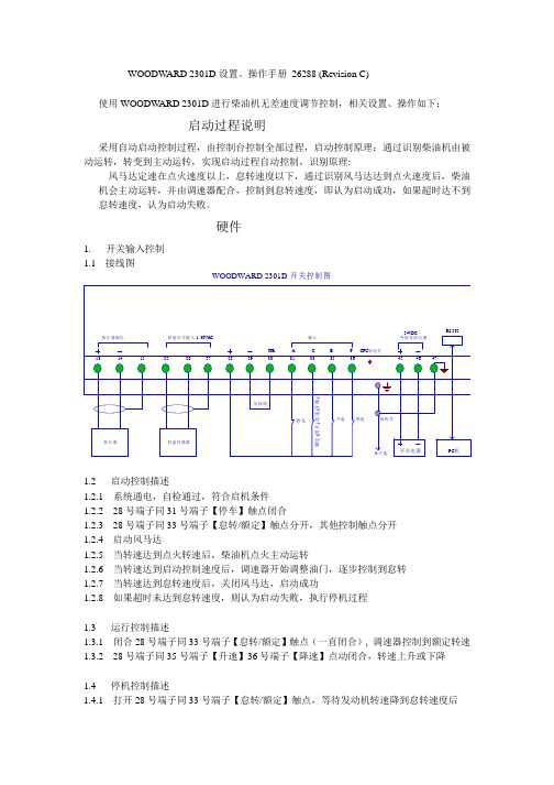
WOODW ARD 2301D设置、操作手册26288 (Revision C)使用WOODW ARD 2301D进行柴油机无差速度调节控制,相关设置、操作如下:启动过程说明采用自动启动控制过程,由控制台控制全部过程,启动控制原理:通过识别柴油机由被动运转,转变到主动运转,实现启动过程自动控制,识别原理:风马达定速在点火速度以上,怠转速度以下,通过识别风马达达到点火速度后,柴油机会主动运转,并由调速器配合,控制到怠转速度,即认为启动成功,如果超时达不到怠转速度,认为启动失败。
硬件1. 开关输入控制1.1接线图WOODWARD 2301D 开关控制图1.2 启动控制描述1.2.1 系统通电,自检通过,符合启机条件1.2.2 28号端子同31号端子【停车】触点闭合1.2.3 28号端子同33号端子【怠转/额定】触点分开,其他控制触点分开1.2.4 启动风马达1.2.5 当转速达到点火转速后,柴油机点火主动运转1.2.6 当转速达到启动控制速度后,调速器开始调整油门,逐步控制到怠转1.2.7 当转速达到怠转速度后,关闭风马达,启动成功1.2.8 如果超时未达到怠转速度,则认为启动失败,执行停机过程1.3 运行控制描述1.3.1 闭合28号端子同33号端子【怠转/额定】触点(一直闭合), 调速器控制到额定转速1.3.2 28号端子同35号端子【升速】36号端子【降速】点动闭合,转速上升或下降1.4 停机控制描述1.4.1 打开28号端子同33号端子【怠转/额定】触点,等待发动机转速降到怠转速度后1.4.2 打开28号端子同31号端子【停车】触点,调速器控制到停车状态注意:不可将【停车】触点直接用于停车,因为可能在额定高转速下,直接切断油路,对发动机不利,所以必须在怠转低转速下,切断油路,使发动机熄火,达到停机目的。
不可将【停车】触点用于紧急停车,以防执行器被卡,达不到紧急停车目的。
注意:在不使用模拟线路控制时,应将模拟线路设置为不使用。
Woodward SPM-D2-11 系列 产品规格 CN37623 负载共享 同步器说明书

SPM-D2-11 系列产品规格CN37623负载共享 同步器适用于三相交流发电机组∙ 针对一个断路器的 同步 ∙ 有功功率(kW) / 无功功率(VAR)共享 (模拟) ∙ 发电机保护 ∙ 有功功率及功率因数控制 ∙ 频率、相位及电压 匹配 ∙ 兼容广泛的GOV 和AVR ∙ 模拟输入以外部控制有功功率设置点 ∙ 断路器时间补偿 ∙ 用于显示发电机和总线值的两线清晰LCD 显示屏 ∙ 前部同步指示器以方便调试 ∙ 可通过HMI 或PC 配置 ∙ 带有 CE 标记 (符合 RoHS2) ∙ UL/cUL 列表说明Woodward 了解发电项目的时间紧迫性。
努力延长部件的使用寿命,这是我们确保客户业务成功的方式之一。
Woodward 已稳定供应和支持 SPM-D 系列同步器长达 20 余年之久。
通过采用先进的简易更换部件,目前 SPM-D2 系列同步器的使用寿命得以延长。
所有 SPM-D2 同步器均设密码保护,可如 之前一样通过 HMI 配置或使用 USB 接口通过工具包配置工具配置。
SPM-D2-11 是一款基于微处理器的同步器,专用于配备 Woodward 或者其它可兼容的速度控制器和自动化电压调节器的两相或三相交流发电机。
SPM-D2-11 同步器可使用模拟或离散输出偏置信号提供自动频率、相位和电压匹配。
它整合了一个断路器同步、负载和功率因数控制或同步负载共享及发电机保护功能。
这款同步器适用于广泛的原动机和发电机,因为可设置其控制信号以适应几种发电机组类型,包括从发动快速的柴油发动机到发动缓慢的燃气轮机。
SPM-D2-11 同步器现提供 1 种基本型号:∙ SPM-D2-11 …/LSXR :提供一相/两线电压测量,具有模拟或离散偏置信号、模拟有功和无功负载共享线路和发电机保护。
特性∙ 电压匹配的相位匹配或转差频率同步∙ 具有 I 级精确度的两相发电机和总线真实 RMS 电压感应 ∙ 可选择操作模式,如 SPM-A (运行、检查、允许和关闭) ∙ 同步检查和同步时间监控 ∙ 按需 CB 失效母线关闭∙ 两个模拟负载共享线路,用于负载/无功功率共享 ∙ 电源并行运行中的有功功率和功率因数控制 ∙ 孤网运行中的电压和频率控制∙ 根据参数(2 个值)或通过 0/4 到 20 mA 模拟输入的发电机真实功率设置点 ∙ 柔性卸载和继电器输出的功率限制值∙ 控制输出:离散提高/降低所有变型中的速度和电压或模拟信号(电压、电流和 PWM ) ∙ 发电机一相 CT 感应,具有功率、过载、电压和频率保护 ∙ 用于操作、警报和测量值显示和参数化的两线清晰液晶显示屏 ∙ 前部配有同步指示器,可指示断路器状态/控制活动 ∙ 参数的多级密码保护∙可通过 USB 配置的 Woodward ToolKit™ 软件 ∙ 两种内置语言:英文、德文新特性 ✓可通过 USB 连接至 PC ✓支持工具包配置✓针对所有变型的密码保护✓与 SPM-D 具有相同的外观和界面 ✓轻松更换option (please order brackets P/N 8923-1023)Front view2008-04-28 | SPM-D Dimensions spmdww-0818-ab.SKFBottom view722735Back view with connecting terminalsConfiguration portConfiguration portSPM-D11The presence of the terminal strips depends on the Package configuration规格(更多详细信息请参阅特定手册)电源 ........................ 12/24 V DC (9.5 到 32 V DC ) 固有消耗 .................................... 最大 8 W 环境温度(运行) ....................... -20 到 70 °C 环境湿度 ................................. 95%,不凝结 电压 ................. (both ranges within one unit ondifferent terminals, /)[1] 100 Vac 额定 (V 额定) .................. 63/110 V AC 最大值 (V 最大值) .................... 150 V AC 及 [4] 400 Vac 额定 (V 额定) ............... 230/400 V AC 最大值 (V 最大值) .................... 300 V AC 额定冲击电压(V 冲击) .... [1] 2.5 kV 、[4] 4.0 kV 精确度 ........................................ 等级 1 测量频率 ..................... 50/60 Hz (40 到 70 Hz ) 线性测量范围 .............................. 1.25 x V 额定 输入电阻 ............. [1]0.21 兆欧姆、[4]0.696 兆欧姆 电流 额定 (I 额定) [1]…/1 A、[5] … /5 A 线性测量范围 ................................ 3.0×I 额定 负荷 ....................................... < 0.15 VA 额定短时过载电流 (1 s) ...... [1] 50×I 额定、[5] 10×I 额定 离散输入 ........................................ 孤网 输入范围 .................................... 12/24 V DC 输入电阻 ............................... 约 6.8 千欧姆 模拟输入 .................................. 可自由扩展 分辨率 ......................................... 10 位 0/4 mA 到 20 mA 输入 ........................ 250 Ohms继电器输出 ........................................ 孤网 触点材料 ......................................... AgCdO 负载 (GP) (V 连续、继电输出) AC : ............... 2.00 A AC @250 V AC DC :2.00 A DC @24 V DC /0.36 A DC @125 V DC /0.18 A DC @250 V DC 控制器负荷 (PD) AC : .............................. B300 DC :1.00 A DC @24 V DC /0.22 A DC @125 V DC /0.10 A DC @250 V DC 模拟输出(孤网) ............................ 可自由扩展 类型 ............................. ± 10 V/± 20 mA/PWM 绝缘电压(连续,AVR 输出) ...................... 300 V AC 绝缘电压(连续,Gov 输出) ...................... 100 V AC Versions ........................ ±10 Vdc, ±20 mA, PWM 分辨率 ........................................... 12 位 ± 10 V(可扩展) ............................... 内电阻 ± 20 mA(可扩展) ................... 最大载荷 500 Ohms 外壳 前面板嵌入式安装 ......... 类型 APRANORM DIN 43 700 尺寸 WxHxD .............. 142 × 72 × 122 mm 前部剪切 WxH ......... 138 [+1.0] × 68 [+0.7] mm 连接 ............................... 螺丝/插头端子取决于 连接器 1.5 mm² 或 2.5 mm² 前部 .......................................... 绝缘表面 保护系统/密封 ............................... 正确安装时 前部 .............................. IP42 前部 ...... IP54(带垫圈 P/N 8923-1037) 后部 .............................. IP20 重量 .......................................... 约 800 g 扰动试验 (CE) ................. 根据适用 EN 指南进行试验 列表 ........................... CE 、UL/cUL 一般地区列表 船舶(待定) ........... LR (型号审批)、ABS (型号审批)尺寸端子图相关产品∙负载共享同步器SPM-D2-10(产品规格 # 37622)∙数字同步器和负载控制器 DSLC-2(产品规格 # 37493)∙主站同步器和负载控制器 MSLC-2(产品规格 # 37494)∙负载共享速度控制器2301E(产品规格 # 03404)∙负载共享模块LSM(产品规格 # 82686)∙SPM-A同步器(产品规格 # 82383)∙发电机组学习模块(产品规格 # 03412):P/N 8447-1012联系方式北美洲和中美洲电话:+1 970 962 7331 ✉*****************************南美洲电话:+55 19 3708 4800 ✉************************欧洲电话(斯图加特):+49 711 78954 510电话(肯彭):+49 2152 145 331✉****************************中东和非洲电话:+971 2 6275185 ✉*************************俄罗斯电话:+7 812 319 3007 ✉****************************中国电话:+86 512 8818 5515 ✉***************************印度电话:+91 124 4399 500 ✉***************************东盟和大洋洲电话:+49 711 78954 510 ✉***************************以变更为准,错误除外。
woodward TG13 TG17调速器使用手册范本

警告在安装、操作或维护本设备前,应通读本手册以及与所进行工作有关的所有其它出版物。
应遵循安全指导和注意事项,不按照说明书会引起人身伤害和/或财产的损失。
发动机、透平或其它类型的原动机应配置超速(超温或超压,在合适的场合)停机装置,这些停机装置应完全独立于原动机的控制设备以防止若机械-液压调速器或电子调节器,执行机构、燃料控制器、传动机构、杠杆机构或被控设备故障时的失控飞车引起的发动机、透平或者其它类型原动机的损坏及人身伤亡事故。
当本手册有重大修改时,手册编号所赋字母按字母表的顺序变为下一个字母。
修改的容由其边上的竖线表明。
WOODW ARD调速器公司保留随时修改本出版物的任何部分的权利。
WOODWARD公司所提供的资料被确认是正确和可靠的。
除非另有明确承诺,对于本手册的使用,WOODW ARD调速器公司不负任何责任。
WOODW ARD调速器公司1984年保留所有权利目录第一章概述序言说明参考文献第二章安装序言接收贮存驱动轴转向连杆的连接输出油转速调整连杆热交换器的安装(任选)供油何时需要热交换器?第三章调速器的动行和调整序言首次运行转速不等率不等率的调整第四章作用原理序言运行说明油压和分配飞锤的作用导向阀的功能不等率调整杠杆的功能第五章故障排除外表检查定义摆动波动振荡第六章更换零件更换零件资料图示清单1-1 调速器的输出1-2 TG-13调速器2-1 泵壳组件2-2 泵壳组件2-3 油泵传动销的位置2-4 泵壳组件2-5 调速器驱动轴顺时针旋转的装配2-6 调速器驱动轴逆时针旋转的装配2-7a 螺钉转速调整,铸铁壳体TG-13和TG-17调速器的外形尺寸图2-7b 杠杆转速调整,铸铁壳体TG-13和TG-17调速器的外形尺寸图2-7c 杠杆转速调整,压模铸铝壳体TG-13和TG-17调速器的外形尺寸图2-7d 螺钉转速调整,压模铸铝壳体TG-13和TG-17调速器的外形尺寸图2-8 热交换器接口的位置2-9 热交换器的管路示意图3-1 不等率调整杠杆的移动4-1 TG-13和TG-17示意图(小)4-1 TG-13和TG-17示意图(大)6-1 铸铁壳体,螺钉转速调整TG-13和TG-17调速器的零件6-2 TG-13和TG-17顶盖组件的零件(杠杆转速调整)用于铸铁壳体的TG-13和TG-176-3 压模铸铝壳体、螺钉转速调整TG-13和TG-17调速器的零件6-4 压模铸铝壳体、螺钉转速调整,带加长驱动轴TG-13和TG-17调速器的零件6-5 TG-13和TG-17顶盖组件的零件(杠杆转速调整)用于铸铝壳体的TG-13和TG-17第一章概述序言本手册04042提供了有关WOODW ARD TG-13和TG-17调速器安装、运行和调整、作用原理、故障排除和更换零件的一般说明。
WOODWARD 2301D设置、操作手册

WOODWARD 2301D设置、操作手册26288 (Revision C)使用WOODW ARD 2301D进行柴油机无差速度调节控制,相关设置、操作如下:启动过程说明采用自动启动控制过程,由控制台控制全部过程,启动控制原理:通过识别柴油机由被动运转,转变到主动运转,实现启动过程自动控制,识别原理:风马达定速在点火速度以上,怠转速度以下,通过识别风马达达到点火速度后,柴油机会主动运转,并由调速器配合,控制到怠转速度,即认为启动成功,如果超时达不到怠转速度,认为启动失败。
硬件1. 开关输入控制1.1接线图WOODWARD 2301D 开关控制图1.2 启动控制描述1.2.1 系统通电,自检通过,符合启机条件1.2.2 28号端子同31号端子【停车】触点闭合1.2.3 28号端子同33号端子【怠转/额定】触点分开,其他控制触点分开1.2.4 启动风马达1.2.5 当转速达到点火转速后,柴油机点火主动运转1.2.6 当转速达到启动控制速度后,调速器开始调整油门,逐步控制到怠转1.2.7 当转速达到怠转速度后,关闭风马达,启动成功1.2.8 如果超时未达到怠转速度,则认为启动失败,执行停机过程1.3 运行控制描述1.3.1 闭合28号端子同33号端子【怠转/额定】触点(一直闭合), 调速器控制到额定转速1.3.2 28号端子同35号端子【升速】36号端子【降速】点动闭合,转速上升或下降1.4 停机控制描述1.4.1 打开28号端子同33号端子【怠转/额定】触点,等待发动机转速降到怠转速度后1.4.2 打开28号端子同31号端子【停车】触点,调速器控制到停车状态注意:不可将【停车】触点直接用于停车,因为可能在额定高转速下,直接切断油路,对发动机不利,所以必须在怠转低转速下,切断油路,使发动机熄火,达到停机目的。
不可将【停车】触点用于紧急停车,以防执行器被卡,达不到紧急停车目的。
注意:在不使用模拟线路控制时,应将模拟线路设置为不使用。
woodward lq25 使用手册

woodward lq25 使用手册
在安装、操作或维修本设备之前,请阅读本手册和与工作相关的所有其他警告,实践所有设备和安全指示及预防措施。
请遵照指示,取消人身伤害或财产损失。
发动机、涡轮机或其他类型的原动机应配备超速关闭装置,以防止失控或可能造成人身伤害、生命损失或财产损坏。
超高速停车装置必须完全独立于原动机控制系统,超温或超压关闭装置也可在适当的情况下有利于安全。
对使用交流发电机或充电装置的控制系统造成的倾覆损坏,请确保充电装置已关闭,请断开电子控制包括状态敏感部件。
观察火光。
馆放电体小手柄控制装置电源关闭控制,接触接地系统,并在处理塑料、乙烯基和施托坦,抗静电版除外时保持接触。
不要用手或用导电装置触摸印刷电路板上的元件或导体。
警告表示一种潜在的危险情况,如果不能避免,可能导致死亡或重伤。
汽轮机WOODWARD505操作指南

操作指南简介键盘和显示器505E的服务面板由调速器前面板上的键盘和LED(发光二极管)显示器组成。
LED显示器可以显示2行(每行24个字符),用来显示运行参数和故障检测参数,使用的语言是简单英文。
通过505E前面板上的30个按键可以实现全部的控制操作。
操作控制透平时无需另外的控制面板,所有的透平控制功能都能通过505E的前面板执行。
下面将对每个键的功能作一说明。
具体有些说明请参见505E说明书操作流程图(第5章),里面详细的介绍了每个功能键下的菜单,如何操作,请仔细阅读。
SCROLL (翻页键): 键盘中央的大菱形键,菱形的四个角上各标有一个箭头。
◄,►(左、右翻动):在编程或运行模式下使功能块显示左、右移动。
▲,▼(上、下翻动):在编程或运行模式下使功能块显示上、下移动。
SELECT(选择键): 用于505E显示器上行或下行变量的控制选择。
符号@用于指示哪一行(变量)能通过ADJ键来进行调整。
只有当上、下均有可调整变量(动态、阀门标定模式)时,才会使用SELECT键和@符号来决定哪一行的变量可被调整。
当显示器上只有一个可调整参数时,SELECT键不能改变@符号的位置。
ADJ (调整键): 在运行模式下,▲增大可调参数,▼减小可调参数。
PRGM (编程键): 当调速器处于停机状态时,用该键可进入编程模式。
当调速器处于运行模式时,用该键可进入程序查看模式。
在程序查看模式下,程序只能查看,不能修改。
RUN(运行键): 当机组准备就绪后,按RUN键发出一个透平运行或启动的命令给505E。
STOP(停止键): 一旦给予确认,触发透平控制停机(运行模式下)。
通过服务模式设定(在‘键选项’下)可以禁用STOP命令。
RESET(复位键):用于复位/清除运行模式下报警和停机。
在停机后按该键,还能使调速器返回到((Controlling Parameter / Push Run or Prgm)状态。
0/NO: 输入0/NO或退出。
WOODWARD调速器说明书02013
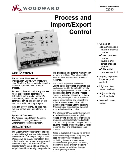
Operation of the Low Signal Select (Inverse/Direct) Process Import/Export ControlThe Process Import/Export control compares the input signals to operator-set references. The difference between each input and the reference setting is sent to a circuit which selects the lower speed or power from the prime mover. The output of this circuit is sent, as an operating voltage, to a load or speed control. The load or speed control then changes or maintains the prime mover load or speed and, in turn, the input to the Process Import/Export Control.The Low Signal Select control offers a choice of three different modes of action:• Inverse Process Control:Controls a process where the sensed input signal decreases as the load or speed increases. (Example: where the sensed input is inlet pressure. Also used for import power control.)• Direct Process Control:Controls a process where the sensed input signal increases as the load or speed increases. (Example: where the sensed input is exhaust pressure. Also used for export power control. May be used forImport/Export control with a 4–20 mA transducer.) • Inverse and Direct Process Control:Uses both inverse and direct process inputs to control a process. The controlling action of the Process Control is determined by the sensed-input signal which requires the lowest prime-mover load or speed. (Examples: The Process Control acts as an Inverse Process Control when the controlling input is inlet pressure. The Process Control acts as a Direct Process Control when the controlling input is outlet pressure.)Differential Process ControlThe Differential Process Control subtracts the inverse process input from the direct process input and compares the difference to an operator-set reference. The Process Control output voltage is then sent to a load or speed control which changes or maintains the load or speed of the prime mover to maintain the required differential input to the Process Control.The Differential Process Control is capable of differential process control only. A differential control is required for Import/Export control of electrical generation when a –5 to + 5 Volt or –20 to +20 mA transducer is used.Process Import/Export Control Outline DrawingSPECIFICATIONSInputs from Controlled Parameter1–5 Vdc or 4–20 mAdc signal (0–10 Vdc may be used when using an external control point potentiometer.)±5 Vdc or ±20 mAdc transducer is used with differential unit for import/export control.Outputs:Compatible with most Woodward electronic speed controls and load-sharing controls.Output impedance determined by setting an internal switch.Selections include: High impedanceimpedanceLowLow signal selectHigh signal selectAmbient Temperature Range–40 to +71 °C (–40 to +160 °F)Power SupplyLow Voltage Model Compatible with 12, 24, or 32 Vdc power systems (10 Vdc minimum, 40 Vdcmaximum)High Voltage Model Compatible with 100 to 120 Vac, 45 to 440 Hz, or 125 Vdc (88 to 132 Vac or90 to 150 Vdc)AdjustmentsHigh Limit 0 to 8 Vdc (range)Low Limit –0.6 to high limit settingOptional External High Limit 0 to internal high limit settingInverse Control Point 0 to 5.5 Vdc or 0 to 22 mAdcDirect Control Point 0 to 5.5 Vdc or 0 to 22 mAdcDifferential Units Direct Control Point –5.5 Vdc to 5.5 Vdc (with inverse control point fully clockwise and 0 to 11Vdc external direct control point)Droop 0 to 7.5% with 1 to 5 Vdc or 4 to 20 mAdc input and 0 to 3 Vdc outputGain For setting process control system stability and response time ConstructionWeight: 1.0 kg (2.2 lb)—steel case with durable epoxy-based paint finishTO SPECIFY AN IMPORT/EXPORT CONTROLThe following text is suggested to describe a Process Import/Export control in a system specification:The Process Import/Export control will provide inverse and/or direct process control functions based on watt transducer or process transducer inputs. The Process Import/Export control will be available with either high voltage (88–132 Vac or 90–150 Vdc) or low voltage (10–45 Vdc) power supply inputs. The Process Import/Export control will be available with either Low Signal Select or Differential Process functions. The Process Import/Export control will have on board high limit, low limit, gain, and process set point adjustments. An external high limit potentiometer input will be standard on the Process Import/Export control. The Process Import/Export control will provide 12 or 24 Vdc isolated power supplies for use in providing power for the watt or process transducers. This power supply shall have a current output capacity of 50 mA dc for both 12 and 24 volt power supply outputs. The Process Import/Export control must be UL Listed and CSA Certified (Woodward Governor Company Process Import/Export control or equivalent).WoodwardIndustrialControls PO Box 1519Fort Collins CO, USA80522-1519 1000 East Drake Road Fort Collins CO 80525 Ph: +1 (970) 482-5811 Fax: +1 (970) 498-3058Distributors & Service Woodward has an international network of distributors and service facilities. For your nearest representative, call theFort Collins plant or see the Worldwide Directoryon our website.Corporate Headquarters Rockford IL, USAPh: +1 (815) 877-7441 T his document is distributed for informational purposes only. It is not to be construed as creating or becoming partof any Woodward Governor Company contractual or warranty obligation unless expressly stated in a written sales contract.© Woodward Governor Company, 1988All Rights ReservedTypical System Block DiagramsFor more information contact: 01/12/F。
Woodward 505 使 用 说 明 书

Woodward 505 使用说明书1、概述WOODWARD 505是美国WOODWARD(伍德瓦特)公司日本分公司生产的,以微处理机为基础的数字式调节器。
采用16位CPU,每14ms 完成一次计算循环。
面板上带有一个26键的键盘和液晶显示窗口(LCD),可以通过键盘和LCD对调节器进行操作。
LCD显示分二行,上面一行为实际运行参数值,下面一行为设定值。
505具有二种工作方式,编程方式(或称组态)和运行方式。
所谓组态,即按汽轮机的用意,在选择项目中挑选出需要的内容。
组态完后便可进入运行方式来操作汽轮机从起动到停机的整个过程。
为了减少将阶跃干扰传入系统的可能性,在505组态完后可移动调节器机壳内的程序跨接器闭锁程序方式的入口通路,这样在汽轮机运行时将不能再使用程序方式。
2、键盘说明2.1、505键盘上26个薄膜开关的位置排列见下图。
2.2、各键的功能说明如下:FUNC(↑)/FUNC(↓)(function):向左或向右移动整个功能模块。
STEP(↑)/STEP(↓):在某一功能模块中向上或向下移动模块。
ADJ(↑)/ADJ(↓)(adjust):在运行方式中增大或减小任一可调参数。
DYN(dynamics):在运行方式中,调出控制执行机构位置参量的动态设定。
GAIN:在运行方式中,激活被显示动态比例增益设定(必须先按DYN 键,随后再依次作适当的动态校正)。
RST(reset):在运行方式中,激活被显示动态比例增益设定(必须先按RST 键,随后再依次作适当的动态校正)。
PRG(program):按此健,调节器由CONTROLLING PARAM/PUSH RUN OR PRG)状态转入程序方式。
RUN:按此健,调节器由CONTROLLING PARAM/PUSH RUN OR PRG)状态转入运行方式。
STOP:在程序方式中按此键调节器返回到准备就绪状态;在运行方式中,按此键经核实后则引发汽轮机可控停机。
WOODWARD调速器说明书02010b

© Woodward Governor Company, 1993 All Rights Reserved
98/7/L
MAGNETIC PICKUP
OUTLINE DRAWING
For more information contact:
INSTALLATION
The MPU is usually mounted radially to the gear, either through the housing or on a rigid bracket. If the MPU must be mounted off the face of the gear, be sure to check for gear end play in addition to gear runout.
Regional Sales Offices
Canada, Québec China, Beijing Czech Republic, Plzen Germany, Tettnang Korea, Pusan Mexico, Mexico City New Zealand, Christchurch Poland, Warsaw United Arab Emirates, Abu Dhabi United States, Alabama, California, Illinois, Pennsylvania, Texas, Washington
- 1、下载文档前请自行甄别文档内容的完整性,平台不提供额外的编辑、内容补充、找答案等附加服务。
- 2、"仅部分预览"的文档,不可在线预览部分如存在完整性等问题,可反馈申请退款(可完整预览的文档不适用该条件!)。
- 3、如文档侵犯您的权益,请联系客服反馈,我们会尽快为您处理(人工客服工作时间:9:00-18:30)。
WoodwordSPM-A同步器安装操作和标准手册内容第一章概述……………………………………………………………..….警告注意事项…………………………………………………………....符合EMC标准………………………………………………...………介绍…………………………………………………………………….描述……………………………………………………………………..操作原理……………………………………………………………...….同步器输入端………………………………………………………….操作模式……………………………………………………………...发电机同步……………………………………………………………电压匹配……………………………………………………………... 第二章放电须知……………………………………………………………第三章安装验货………………………………………………………………………..位置……………………………………………………………………….安装……………………………………………………………………….电气接线…………………………………………………………………..至发电机的接线…………………………………………………………..至负荷分配器和速度控制器的连线……………………………………..最优速度输出…………………………………………………………母线-母线并机………………………………………………………...使发电机投入母线……………………………………………………电压调节继电器输出接线……………………………………………并机断路器和闸接线…………………………………………………第四章标准与核查概述…………………………………………………………………..预检查…………………………………………………………………滞后时间调节…………………………………………………………测试和调整……………………………………………………………试验台调节………………………………………………………动态检查………………………………………………………………稳定性和增益调节…………………………………………….频率调节……………………………………………………….偏移调节………………………………………………………..相位偏移调节………………………………………………….电压偏移调节…………………………………………………. 第五章服务产品服务选项………. …………………………..…………………返回设备修理…….. ……………….………………………………控制器包装…….. …………………….……………………………授权系列号…………………………………………………………替代部分…………………………………………………………..联系Woodward……………………………………………….….产品售后服务…………………………………………………….Woodward规范…………………………………………………..安装接线图……………………………………. 1-1 控制接线概述……………………………………………………. 1-2 系统方框图………………………………………………………1-3 功能方框图………………………………………………………1-4 出厂接线图………………………………………………………3-1 典型SPM-A同步接线…………………………………………. 3-2母线-母线并接………………………………………………. 3-3滞后时间设置………………………………………………..第一章概述常规注意事项●根据加拿大CSA和美国的UL标准,SPM-A一般安装在无危险的位置。
可参考下列表格。
●接线权限。
EMC标准根据EMC标准89/336/EEC和修正准则,Woodward公司研制开发了本产品。
它作为独立的元件与发动机配套使用。
Woodward公司宣布本产品应按照EN50081-2和EN50082-2标准安装、操作。
并按本手册所介绍的内容正确接线。
介绍本手册介绍SPM-A的安装、操作原理。
用于调节发电机的转速、相位,使之与其它发电机/母线匹配。
小中型柴油机需要快速的动态特性,而涡轮机组、大型柴油机、气体/汽油发动机、蒸汽和气体涡轮机需要较慢的动态特性。
有两个版本的SPM-A同步器可供选择—带/不带电压匹配器。
两版本都针对大部分发动机设计。
对于倾斜式火花点火式气体发动机,SPM-A的附加功能调整详见应用手册01301。
描述同步器通过偏置未联机的发电机组的速度,以使其频率与另一台发电机或母线匹配.当两者一致时,自动发出一个闭合信号,控制并机断路器经过一个特定的匹配时间后合闸。
SPM-A是一个相位互锁回路的同步器,可以达到一个完善的频率和相位,SPM-A具有电压匹配功能的同步器根据电压可以提供一个附加的上升/下降信号(继电器的触电闭合)到发电机的电压调整器。
在闭合断路器之前,应考虑SPM-A的触点的耐压值。
单单元同步器可以使单台发电机与母线合闸;对于多单元同步器,最多一台同步器可以使7台电机与母线合闸。
两种型号的同步器都有3种输出选项:高阻抗,低阻抗和EPG。
高阻抗输出供给单单元同步器适用,与Woodward 2301控制器配套;选择低阻抗也是单单元同步器使用,用Woodward 2301A,2500或通过发电机负载传感器用电子功率(EPG)控制,;不用负载传感线的EPG控制,使用(EPG)输出口。
两个单元的同步器都有以下特征:●120或208/240V交流输入●10°的相位偏差●1/8,1/4,1/2或1s滞后时间,(使用内部开关可选择,默认值为1/2s) 按照标准SPM-A同步器,根据电压匹配为1%的电压匹配,其它选项见下表:选择表型号频率相位角电压匹配9905-00150/60Hz ±10°No9905-02850/60Hz ±10°1%9905-0029907-0299905-003 50/60Hz ±10°5%9905-004 50/60Hz ±5°No9905-005 50/60Hz ±5°1%9905-006 50/60Hz ±10°0.5%9905-008 400Hz ±10°1%9905-009 50/60Hz ±10°10%9905-107 ±10°5%理论操作本部分描述了两种同步器的SPM-A的理论操作。
图1-1介绍SPM-A的匹配电压,图1-2显示了同步器系统的方框图,图1-3显示了功能块图。
同步器输入SPM-A同步器检查母线相位与待并电机的频率和相位。
来自母线与待并发电机的信号被单独输入到信号调整装置回路,每一个信号调整装置都是一个滤波器,它随输入信号的变化而改变,因而可以准确测量输入信号。
信号调节装置中相位偏差电位计可以弥补相位误差。
(该调节工厂已设定。
当安装了变压器,相位偏差应重新调节)。
信号调节装置也可以放大母线和发电机的信号使之适应相位检波器。
操作模式一个需要用户安装的模式开关(单极,四极)控制继电器驱动。
此开关必须连结到同步器触电(10-13),清参考接线图。
四个位置为:OFF(关),RUN(运行),CHECK(核查),PERMISSIVE(允许)。
当开关在OFF位置时,同步器不允许操作。
运行模式RUN位置允许正常的同步器操作和断路器操作,断路器闭合信号。
速度偏差信号发出断路器闭合信号,大约需要1s完成。
当经过1s后回路被锁定,使同步器不工作。
当发电机连线与母线断开后,相对相位角超过相位窗口的限制,,此回路自动复位。
CHECK(检查)模式允许同步器进行正常的操作和电压匹配,但不向断路器发出闭合信号。
允许模式允许同步器检查合适的同步点,但同步器的操作并不影响发动机的速度(在电压匹配模式中也不影响匹配电压)。
如果相位和频率在合适的限制范围内,同步器可以发出同步信号(此模式不检查电压)。
更多的关于相位角和闭合断路器的信息,参考Woodward 应用手册50511。
发电机同步相位检波器比较两个信号,并确定发电机和母线回路的区别。
当有所不同时,速度偏差回路发出一个合适的信号给负荷分配器和速度控制器。
这个信号根据发电机是滞后还是超前,可以增加/减少电机的速度。
信号放大与滞后/超前信号成正比(相位不同)。
相位窗口回路,延迟时间回路和断路器闭合回路接受从相位检波器过来的输入信号,根据这些从发电机和母线过来的信号,相位窗口回路检查其相位角。
当相位角小于选择的角度值时(在窗口范围内),延时时间回路开始计时,确保在合闸时两相位同步。
当相位角和滞后时间核查无误后,断路器闭合回路发出信号给驱动继电器,使之禁止/动作。
使能回路进行二级的相对相位角核查,并转动一个指示器。
当断路器闭合回路和使能回路的条件都满足时, 发出闭合信号,断路器大约在1s内动作。
端子处提供常开。
当母线无电压时,具有/不具有电压匹配的同步器,都不会使同步器发出合闸信号。
也不会向负荷分配器和速度控制器发出信号,更不会使断路器合闸。
如果母线无电压,模式开关必须打在OFF位置。
电压匹配电压补偿回路比较发电机和母线的电压,如果两者不同,则回路发出适当的上升/下降命令给电压调节器(这是通过继电器触点来完成的,参考图1-3和图1-4)。
此回路中由一个电压补偿电位器,用来弥补内部回路的不同。
当母线和发电机并上后,应再次适当调整此补偿值。
电压补偿回路也提供输入信号给驱动/禁止并机继电器。
发出断路器闭合命令之前,发电机和母线的电压差值应在允许的电压范围之内。
当闭合断路器信号发出后,电压匹配回路不工作。
图1-1 控制轮廓图图1-2 系统功能图图1-3 系统功能块第2章静电充放电须知所有的电子设备都是静态敏感元件,有一些特别敏感。
为保护这些元器件免受静电干扰,必须采取特殊的措施来消除充/放电时的干扰。
按如下警告正确操作:1.在手接触同步器前,手握金属体使身体完全放电;2.最好穿棉织品材料的衣服,不要穿合成材料制成的衣服,以免衣服产生静电;3.塑料制品,乙烯材料(例如塑料,相交,泡沫杯子,泡沫托盘,香烟袋,玻璃纸,乙烯树脂制成的书本或文件夹,塑料杯子,和塑料烟灰缸)远离控制装置,尽可能不在模块附近的工作区域存放。
4.禁止将印刷板电路从柜盒内取出,如要取出应遵守如下警告●手只能接触板子边缘;●禁止触摸覆铜板,元器件;●当更换PCB板时,应存放在防静电的袋中。
第3章安装本章主要提供的信息是SPM-A同步器的安装地点、安装和接线。
拆装在拆装同步器之前,参考内部手册外表封皮的警告与注意事项。
拆装时应检查是否有破坏的痕迹,如变形、面板凹痕、刮伤、松懈或毁坏的痕迹。