2021年功率计E4418B中文使用说明介绍模板
信号源使用说明

Zero/Cal键,选择Zero进行清零; 将功率探头接到50MHz功率参考输出端口,Cal键进行
仪器、探头和连接电缆的校准; 校准完成后将Power Ref打到On的状态,此时显示的
功率值应为0dBm,再将Power Ref打到Off状态; Frequency/cal/Fac键输入测试信号的频率值该频率对
描范围为10dB,则信号源将从-15dBm 扫到-5dBm); 4. 设置扫描步进值STEP,最小为0.1dB; 5. 使用RF ON键将信号打到开的状态。
21
脉冲信号源的使用
22
脉冲信号源81101A
81101A
23
81101A参数设置菜单界面
24
功率计的使用
25
峰值功率计E4416A
26
连接被测信号进行测试。
30
峰值功率计E4416A
用E9320系列功率探头可以直接进行峰值功率 测试,不需要输入占空比和校准因子;
可以看到信号的波形; Channel键进入菜单后可进行各项参数的设置。
31
谢谢
32
STOP 1000 MHz
6
功率扫描的应用
放大器压缩点测试
Power Out
1 dB compression point
Input 1 dB compression point Power In
7
几种常用信号源及其技术指标
2023B
8
几种常用信号源及其技术指标
2023B(标配)
频率范围:9KHz -- 2.05GHz 功率范围:-140dBm -- +13dBm 频率分辨率:1Hz 幅度分辨率:0.1dB 相位噪声:载波为1GHz时在 20KHz频偏处相位
功率计E4418B中文使用说明书
E4418B功率计和E4412A型功率传感器使用手册安捷仑技术公司E4418B功率计使用手册目录第一章:准备工作第二章:功率计操作第三章:参考菜单第四章:错误信息第五章:规格第一章:准备工作第一节:打开功率计1.接上电源线,打开功率计开关,此时功率指示灯亮(绿色),功率计将自检,如果自检不成功,错误指示灯将亮,请与安捷仑技术公司售后服务部联系。
注意:输入电压的范围应在交流85伏到264伏之间。
在极低的环境温度下,本仪器需要预热几分钟。
2.按照面板屏幕的显示按软键调整对比度,如果软键未出现,重复按预置键(Prev)直到出现。
3.接上功率传感器。
4.在精确测量前应保证至少预热30分钟。
测量前信号要调零、校正传感器。
第二节:前面板各键的功能1.预置键。
Preset/local2.显示键。
在前面板的左边从上数第二和第三个键。
▲▼表示在上下窗口之间选择,另一个表示是否分两个窗口显示。
3.电源开/关键。
在前面板的左下角。
4.系统/输入键和软键菜单。
System/inputs5.保存/重置键。
Save/Recall6.专用“窗口”键和软键菜单Meas/Setup,Rel/Offset,dBm/W 7.专用“频道”键和软键菜单Frequency/Cal Fac,Zero/Cal。
8.频道输入插座CHANNEL9.功率参考输出插座POWER REF10.上下左右箭头键11.与菜单相关的键Prev和More键12.软键指显示屏右边4个未标字的键,它们是选择键。
第三节:显示形式分两个窗口显示时,上面是数字式显示,下面是逻辑式显示。
1.窗口顶端菜单条。
显示“LCL”自身状态。
“ERR”错误信息。
2.单或双窗口显示区。
3.测量结果区。
4.测量单位显示区。
5.逻辑式显示区。
6.当前显示菜单的页数选择区。
7.任何软键显示区。
8.菜单目录显示区。
9.测量结果超出限制显示区。
10.相关模式打开后的显示区。
11.偏置设定后的显示区。
EH-4使用说明书范文-中文版-图文
EH-4使用说明书范文-中文版-图文简介0.0简介Stratagem这套仪器是一种用来测量地下几米到一公里多深的地球电阻率的特殊大地电磁测深(MT)仪器。
这套仪器既可以使用天然场源的大地电磁信号,又可以使用人工场源的电磁信号,以此来获得测量点下的电性结构。
大地电磁测深(MT)仪器是通过同时对一系列当地电场和磁场波动的测量来获得地表的电阻抗。
这些野外测量要经过几分钟;傅立叶变换以后以能谱存储起来。
这些通过能谱值计算出来的表面阻抗是一个复杂的频率函数,在这个频率函数中,高频数据受到浅部或附近的地质体的影响,而低频数据受到深部或远处地质体的影响。
一个大地电磁(MT)测量给出了测量点以下垂直电阻率的估计值,同时也表明了在测量点的地电复杂性。
在那些点到点电阻率分布变化不快的地方,电阻率的探测是一个对测量点下地电分层的一个合理估计。
Stratagem这套系统是由两个基本组件构成:一个接受机,一个发射机。
在高频段,天然信号通常比较微弱,使用发射机能够提高数据的质量;对于某些应用或某些情况下,由发射机提供的额外的高频信号我们可以不必使用。
Stratagem这套仪器可以有效的用于地下水调查、环境的地下特征调查、矿产与地热勘探及工程研究。
因为该仪器的供电电池既灵巧致密又便携,所以即使在崎岖的山区和恶劣的地区也能顺利的操作和工作,Stratagem系统的快速采集速度和便携性为我们的勘察设计提供了灵活性。
表面阻抗可以很快的以电阻率的形式显示出来,也可以一组组处理,并实时在剖面中呈现出来,这种实时显现的灵活多样性能够让调查者根据对初步处理和测量结果的分析而改变测量设计。
EH-4操作说明书系统配件1.0系统配件以下说明的是Stratagem的各个组件。
该系统配置的标准接收机设计的采集频宽为100KHz到11.7Hz。
可选的接收机组件和标准的接收机一块使用它的采集频率可以从1000Hz扩展到0.1Hz。
标准配件及它们的连接见图一和图二。
ACPR测试指导书
ACPR测试指导书1 目的指导整机的ACPR测试2 适用范围整机的ACPR测试作业3 作业过程1. 调试仪器与设备所用调试仪器与设备见表1。
2.作业步骤2.1基本规范2.1.1操作人员必须佩带防静电手腕带,穿防静电服、鞋,做好防静电措施。
2.1.2 仪表必须使用三芯电源线,并保证接地良好。
2.1.3仪器在投入使用前须预热约半小时。
2.1.4 不可带电插拔探头或HP-IB电缆,必须关机后操作。
2.1.5 在校表及测试过程中出现异常,应立即断电停止使用仪器。
2.2外观检查和仪器校准用显微镜检查各个元件是否存在有虚焊、漏焊、错焊等现象,防护漆层无脱落,印字清晰。
仪器校准见《信号源使用说明书》、《功率计使用说明书》、《频谱仪使用说明书》。
功率计N1911A校准示例如下:2.2.1 功率计校准(E4418B)开机→Preset→连接探头到POWER REF→Cal→Zero +Cal→Power Ref/ON→看校准是否为0→ Power Ref/Off3.仪器设置1.信号源设置开机→Preset→FREQ→设定频率→AMPTD→设定功率→Mode→Dual ARB→Select Wavefrom→Wavefrom Segments→选中LTE_ACP→Load Segment From Int Media→Mode→Dual ARB→Select Wavefrom→Select Wavefrom(WFM1: LTE_ACP)→Arb Setup→Arb Sample Clock→设置30.72M→ Mode→Dual ARB→ARB off→ARB on2.频谱仪设置开机→Trace/Detector→Trace Average→Sweep/Controt→Sweep Time→设置100ms→Meas→ACP→Center Freq→设定中心频率→Meas Setup→Carrier setup→Configure Carriers→设置Carrier Spacing 20M→设置Measurement Noise Bandwidth 为19.02M→Span→设置为100MHz→Meas Setup→offset/Limits→设置offset Freq为20MHz→Integ BW为19.02MHz→AMPTD→设置Ref Value为10dBm打开信号源Mod on/off,RF on/off开始测试测试功率为Psat倒退3dBm。
Agilent E4418B功率计操作指导书 11
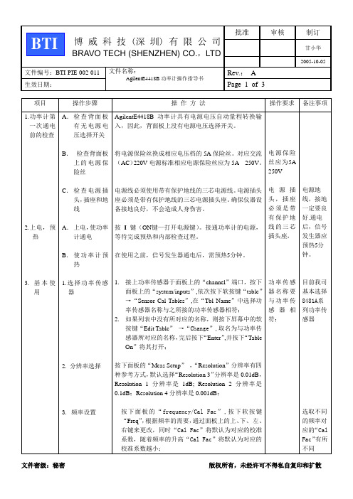
2005-10-05文件编号:BTI-PIE-002-011 文件名称:AgilentE4418B功率计操作指导书Rev.:A生效日期:Page 2 of 3 项目操作步骤操作方法操作要求备注事项4. 功率计归零、校准5. 保存4.Display键5.PRESETLoad键1. 频率设定“Ref CF”默认值是100%或最后一个值;使用面板上的上、下、左、右键修改“Ref CF”;按“%”确认;2. 将功率传感器接至面板上的“POWER REF”端口;3. 按下面板上的“Rel/Offset”键,按下屏幕上的软按键“Offset Off”,即把衰件偏置关闭;4. 按下面板上的“Zero/Cal”键,按下屏幕上的软按键“Power Ref On”,即把功率修正打开,按下“Zero”,等待功率归零后,再按“cal”校准仪器,校准完成;5. 按下屏幕上的软按键“Power Ref Off”,即把功率修正关闭;6. 按下面板上的“Rel/Offset”键,按下屏幕上的软按键“Rel off”;按“offset”输入offset值,该值由网络分析仪测出,按“offset on ”,即把衰减偏置打开;1.功率计归零、校准完成之后,按下面板上的“SAVE/RECALL”键, 按下屏幕上的软按键“SAVE”,遵照屏幕的提示,按下“CONFIRM”即可;2.如果需要更改所要保存的文件名,则按下屏幕上的软按键“EDIT NAME”,使用面板上的上、下、左、右键编写所需的文件名,编写完后,依次按下屏幕上的软按键“ENTER”、“SAVE”、“CONFIRM”即可完成保存。
3.如果需要直接调出文件,则按下面板上的“SAVE/RECALL”键, 使用面板上的上、下、左、右键选择所需的文件名,按下屏幕上的软按键“RECALL”即可。
按下“”键,屏幕中的“上窗口”或“下窗口”将被选中;按下“”键,屏幕中将显示一个窗口或两个窗口;按PRESET键,当分析仪用PRESET键预置时,它将返回到一已知的工作状态。
安捷伦E4418B功率计

安捷伦E4418B功率计介绍安捷伦E4418B是一款高精度的射频功率计,可用于测量射频信号的功率和功率密度,广泛应用于无线通信、雷达测量、微波炉等领域。
技术参数•测量范围:-70 dBm ~ +44 dBm•频率范围:100 kHz ~ 110 GHz•功率分辨率:0.001 dB•不确定度:0.21 dB•输入阻抗:50 Ω特点安捷伦E4418B功率计具有以下特点:高精度该功率计的不确定度仅为0.21 dB,可以提供高精度测量结果。
宽频率范围安捷伦E4418B功率计的频率范围覆盖100 kHz至110 GHz,适用于广泛的射频信号测量需求。
多种测量模式该功率计具有多种测量模式,包括平均功率模式、峰值功率模式和时间域功率模式,可以应对不同的测量需求。
易于操作安捷伦E4418B功率计具有直观的操作界面,可以进行快速方便的测量,并可通过USB接口与计算机进行数据传输和分析。
应用场景安捷伦E4418B功率计广泛应用于以下领域:无线通信该功率计可以用于测量各种无线信号的功率和功率密度,包括移动通信、卫星通信、无线电广播等领域。
雷达测量安捷伦E4418B功率计可以用于雷达系统中的功率测量、校准和故障诊断,提供高精度的测量结果。
微波炉该功率计可以用于微波炉的功率测量和功率调节,保证微波加热的效果和安全性。
使用说明使用安捷伦E4418B功率计需要注意以下事项:1.在使用前应仔细阅读使用手册,并按照说明进行操作。
2.在测量时应尽量避免将功率计暴露在射频信号下,以免对测量结果造成干扰。
3.使用时应保持功率计干净整洁,避免污染和损坏。
4.使用结束后应及时关闭功率计,并将其妥善保管。
结论安捷伦E4418B功率计是一款功能强大、精度高的射频功率计,广泛应用于无线通信、雷达测量等领域,并具有易于操作、多种测量模式等特点,使用时需要注意事项以保证测量结果的准确性。
ICP DAS Inc., LTD. 功率计工具用户手册 [版本1.4]说明书
![ICP DAS Inc., LTD. 功率计工具用户手册 [版本1.4]说明书](https://img.taocdn.com/s3/m/bcf2641476232f60ddccda38376baf1ffc4fe3b0.png)
Power Meter Utility User’s Manual[Version 1.4]WarningICP DAS Inc., LTD. assumes no liability for damages consequent to the use of this product. ICP DAS Inc., LTD. reserves the right to change this manual at any time without notice. The information furnished by ICP DAS Inc. is believed to be accurate and reliable. However, no responsibility is assumed by ICP DAS Inc., LTD. for its use, or for any infringements of patents or other rights of third parties resulting from its use.Copyright and Trademark Information© Copyright 2012 by ICP DAS Inc., LTD. All rights reserved worldwide.Trademark of Other CompaniesThe names used for identification only maybe registered trademarks of their respective companies.LicenseThe user can use, modify and backup this software on a single machine. The user may not reproduce, transfer or distribute this software, or any copy, in whole or in part.Table of Contents1System Description (1)2Before Installation (2)3Software Installation (3)4User Interface Introduction (5)5Utility Operation Procedure (6)5.1Change language (6)5.2Establish connection or perform disconnection with the meter (6)5.2.1Establish COM Port connection with PM-213x / PM-311x (6)5.2.2Establish TCP/IP Connection with PM-213x-MTCP /PM-311x-MTCP (8)5.2.3Perform Disconnection (12)5.3Modify parameters of the power meter (13)5.4Restore the parameters of the meter to default factory settings (14)1 System DescriptionThis document is intended to provide guidelines for ICP DAS Power Meter Utility software tool that applies to ICP DAS Power Meter (e.g., PM-213x / PM-311x / PM-213x-MTCP / PM-311x-MTCP). This software tool has to be installed on PC and it enables to retrieve and display the power measurement values that measured by power meter via COM Port or Ethernet. The users will be able to read the power measurement values and to perform parameter settings of the meter. When connecting with PM-213x / PM-311x by RS-485 communication protocol interface, it requires to convert RS-232 or USB on PC to RS-485 communication interface, converter modules (such as ICP DAS I-7561, I-7520) might be required;When connecting with PM-213x-MTCP / PM-311x-MTCP by Ethernet interface, it must setup the correct IP address to retrieve the power measurement values easily!Features:●By Modbus RTU or Modbus TCP protocol, it enables to connect withICP DAS Power Meter and data retrieving.●Real time monitor power measurement values of the meter.●Real time setting up parameters of the meter.●Restore the parameters of the meter to default factory settings.Before installing ICP DAS Power Meter Utility, please finishing installation of the ICP DAS Power Meter hardware, and make sure all wiring connections are accurate. (Please refer to the user manual for Power Meter). The Power Meter Utility requires the .NET framework version 2.0 to be installed on the target computer. Please follow the link below to get the framework package directly from Microsoft, if required.◆Download Microsoft .Net Framework Version 2.0:Link 1:/en-us/download/details.aspx?id=1639 Link 2:/en-us/download/details.aspx?id=16614◆Download Microsoft .Net Framework Version 3.5:Link 1:/en-us/download/details.aspx?id=21 Link 2:/en-us/vstudio/aa496123Please contact ICP DAS service or visit ICP DAS Intelligence Power Meter product Web site to obtain the latest version of the ICP DAS Power Meter Utility installer. Double click the ICP DAS Power Meter Utility installer to run the installation. Click [Next] to continue.On [Select Installation Folder] page, input path or browse through file dialog box to select the destination folder and select the software user option, click [Next] to continue.Make sure the settings are accurate. Click [Next] to start installation.When the installation process is completed, click [Close] to finish installing program.After the installation is completed, you will find the Power Meter Utility Shortcut on the desktop and in the program menu: [Start]→[AllPrograms]→[ICPDAS] →[ Power Meter] (icon ).4 User Interface IntroductionPower Meter Utility software tool Interface is shown as follow:●Languages: Select your preferred language for the software interface.(English, Traditional Chinese, Simplified Chinese).●Connection Setting: Set up related connection parameter settings forconnecting with the power meter.●Real Time Power Measurements: Display power meter measurementvalues in real time.●Status information: Display power meter status information.5 Utility Operation ProcedurePower Meter Utility makes it easy to retrieve power measurements and modify parameters for systems in real time when connecting with meters.Power Meter Utility enables:●Change Language interface for utility user interface.●Establish connection or perform disconnection of the power meter.●Modify parameters of the power meter.●Restore the parameters of the meter to default factory settings.5.1 Change languageThe preferred language can be set by the following steps:i. Execute Power Meter Utility, and the language change option willappear on the right upper area of the window.ii. Click on the preferred language, currently there are 3 language options: English, Traditional Chinese, and Simplified Chinese.5.2 Establish connection or perform disconnection with the meter5.2.1 Establish COM Port connection with PM-213x / PM-311xi. Because PM-213x / PM-311x support Modbus RTU protocol,select “Modbus RTU” in the Communication Interface.ii. Under the Connection Setting section, select the COM Port that is going to connect with the power meter, input the Timeout interval(unit : ms) and input the Meter ID number. The default Timeoutinterval will be 1000 ms; this value can be modified according tothe quality of the signal in the field.Note: User can click on “Refresh” button to renew the available COM Port of the PC system, and then select the COM Port fromthe dropdown list.iii. Make sure the parameters you input are all accurate, and click on “Connect” button.iv. When the system is trying to connect with the power meter, the status information will show message: “Try connecting”. It will try to connect with the power meter by default factory parameter settings such as: Baud Rate:19200 and Stop Bits: 1.v. If the system fails to establish the connection with the power meter by default factory parameter settings. The system will try other combination of the Baud Rate and Stop Bits. The status information will show the Baud Rate and Stop Bits information.vi. After the utility connecting with the meter, the Meter Parameter Information section will be renewed (as shown below). And the real time power measurements will be displayed under the section of Power Measurements (as shown below).vii. After the connection has been established and the power measurements have been read into the system, the status information will show the time interval the system requires to read all power measurements. This value can be used as a reference for connection quality evaluation.viii. For the PM-311x DO channel attribute setting, it allows user to modify the DO Relay value and Power On value individually by clicking on the “ON/OFF”button of specific channel (as shown below).5.2.2 Establish TCP/IP Connection with PM-213x-MTCP /PM-311x-MTCPi.Because PM-213x-MTCP / PM-311x-MTCP support Modbus TCPprotocol, select “Modbus TCP” in the Communication Interface.ii. Under the Connection Setting section, input the Timeout interval (unit: ms) and input the Meter ID number. The default Timeout interval will be 1500 ms; this value can be modified according to the quality of the signal in the field.iii. Click “Search”to enter the “Communication Interface Setting”window, click ”Search” button to search the available power meter.iv. Select the power meter which you want to modify parameters from the meter list, then click ”Configuration” button to setup the meter parameters. After complete all setting, click “OK”, and return to the meter list windows.v. Select the power meter which utility will connect with, then click “OK” button.vi. Make sure the power meter parameters are all accurate, click “Connect” button.vii. When the system is trying to connect with the power meter, the status information will show “Try connecting” message.viii. After the utility connect with the meter, the Meter ParameterInformation section will be renewed (as shown below). And the real time power measurements will be displayed under the section of Power Measurements (as shown below).ix. For the PM-311x-MTCP DO channel attribute setting, it allows user to modify the DO Relay value and Power On value individually by clicking on the “ON/OFF” button of specific channel (as shown below).x. After the connection has been established and the power measurements have been read into the system, the status information will show the time interval the system requires to read all power measurements. This value can be used as a reference for connection quality evaluation.5.2.3 Perform DisconnectionTo disconnect with the power meter, click on the “Disconnect” button to stop reading power measurements and interrupt the connection.5.3 Modify parameters of the power meterAfter successfully connecting with the meter via Power Meter Utility, the user can modify the parameters of the meter. The new settings will take effect next time when the system trying to establish a connection with the meter.To modify the connection parameters, please follow the steps below:(Using COM Port connection with PM-213x as an example):i. After successfully connecting with the meter, some parameters inputpanel such as Baud Rate, Stop Bits, PT Ratio and CT Ratio willappear to be available to input.●Select appropriate values from the dropdown list of the BaudRate and Stop Bits.●For PT Ratio and CT Ratio, the user can select appropriatevalues from the dropdown list or input the value into the paneldirectly.ii. After finishing setting up the parameters of the meter, click on the “Modify” button to modify the values. The new parameter settings willtake effect in real time. The status information will show “ModifyingPower Meter Parameters…” when performing parametermodification.Please Note :1. There are only PT Ratio and CT Ratio settings for the COM Portconnection with PM-311x.2. There are only PT Ratio and CT Ratio settings for the TCP/IPconnection with PM-213x-MTCP / PM-311-MTCP.3. After finishing the modification of the power meter connectionparameters, the system will temporarily interrupt the connectionwith the meter and will reconnect with the meter again by thenew parameter settings. If the connection is established, thesystem will real time retrieve and display all power measurementvalues. If the system fails to connect with the meter, it willcontinue to try to establish the connection by other Baud Rateand Stop Bits combination.5.4 Restore the parameters of the meter to default factory settingsAfter successfully connecting with the meter via Power Meter Utility, the user can restore the parameters of the meter to default factory settings.●The default factory settings of the PM-213x parameters will be: BaudRate: 19200, Stop Bits: 1, PT Ratio: 1 and CT Ratio: 1●The default factory settings of the PM-311x parameters will be: PTRatio: 1 and CT Ratio: 1●The default factory settings of the PM-213x-MTCP parameters will be:PT Ratio: 1 and CT Ratio: 1●The default factory settings of the PM-311x-MTCP parameters will be:PT Ration: 1 and CT Ratio:1Follow steps below to restore the parameters to default factory settings:i. After successfully connecting with the meter, click on the “Default”button to restore the parameters of the meter to default factorysettings. After the reset take effect, the PM-213x parameters such asBaud Rate, Stop Bits, PT Ratio and CT Ratio will appear to be defaultfactory settings;The PM-311x / PM-213x-MTCP / PM-311x-MTCPparameters such as PT Ratio and CT Ratio will appear to be defaultfactory settings.ii. The status information will show “Return to Default V alues” when the system is trying to restore the parameters of the meter to defaultfactory settings.Please Note :1.After finishing the modification of the power meter connectionparameters, the system will temporarily interrupt the connection with the meter and will reconnect with the meter again by the new parameter settings. If the connection is established, the system will real time retrieve and display all power measurement values. If the system fails to connect with the meter, it will continue to try to establish the connection by other Baud Rate and Stop Bits combination.。
胜利仪器 VICTOR 480B高精度功率计说明书
Power meter的操作方法
By jimson 2019.8
Power meter基本概念 Power meter產品簡介 Agenda Power meter簡要說明 Power meter簡易操作方法
Power meter基本概念
• 何為Power meter? Power meter中文意義為﹕电功率表,功率 表,功率计 。
12.按Cont Trig鍵﹔
13.整個校正完成﹐顯示屏顯示可以 正常運行
13.Power Meter頻率調整 Power Meter頻率調整根據各機種要求來設
定﹐拿BCM 2.5GHz的要求為例﹔
14.調整頻率前按Frequency/Cal Fac鍵,進入 下一及調整菜單﹔
15.按Frequency/Cal Fac鍵后﹐再按Freq鍵 進入調整頻率狀態
9.校正完成后﹐將Power Ref打到off檔,Power Ref燈會熄滅
Power Ref燈會熄滅
10.校正完成后Power Meter顯示屏幕上一個 小人狀態;即提示你要將Power Meter調到工
作狀態﹔這時應該按Trigger鍵
11. 按Trigger鍵后﹐將出現如下畫 面﹔再按Free Run后進入12畫面.
Agilent’s EPM & EPM-P Power Meters WLAN Manufacturing Test
EPM-P Series Power Meters
Peak and Average Power Measurements and Time Gated Measurements (E4416A/17A)
EPM-P系列功率计E4416A与Agilent E9320传感器族构成单机解决方案,它能测量峰值功率、 平均值功率和峰均比,以及时间选通测量。多种多样的触发特性使它能容易地捕获所关注的信号。 EPM系列:可置信的平均功率测量
E4418B功率计校准操作方法概述

直通校准操作方法概述目录1.首先,将功率计复位,即按fpresen键: (2)2.功率计归零 (4)3.频率设置: (6)4.校准 (10)5.参考偏置(Offset)的设置 (14)1.首先,将功率计复位,即按Preset键:图1面板按键图功率计显示如下:图2复位界面图1选择“Confirm”复位结束后显示如下:2.功率计归零按下图选择Zero/Cal 按钮。
图4功率计按键图屏幕显示界面如下:图5功率计归零菜单1选择“Zero”,将显示如下界面:等几秒后,归零结束,将显示下面界面:图7功率计归零菜单3 3.频率设置:选择Frequency/Cal Fac 按钮。
图8功率计面板按键图将显示下列界面图:选择“Freq/50.000MHz”将出现下面界面:图10频率设置界面图2通过上、下、左、右箭头设置频率大小。
图11功率计面板按键图图12频率设置界面图3选择正确的单位(GHz或MHz),频率就设好了,界面如下:4.校准按下图选择Zero/Cal 按钮。
图14功率计按键图屏幕显示界面如下:图15功率计校准界面1将“Power Ref” 设为“On”:图17功率计校准界面2选择“C a l”,将出现如下界面:等几秒后,校准完成,界面如下:图19功率计校准界面4选择“Power Ref”,将此设为“Off”,这样功率计校准就完成了。
图20功率计校准完成界面5.参考偏置(0f60,)的设置当功率计是通过耦合器或一段射频线与被测件连接时,首先要将被测件到功率计探头的损耗测出(可用矢网或信号源带功率计测试),再将此值设到功率计参考偏置中,这样功率计上读数就为被测件输出的功率值。
功率计参考偏置设置方法如下:首先,按Ref/Offset 键。
图21功率计面板按键图将出现如下界面:图22参考偏置设置界面图1选择“O f f s e t/0.000d B”,将出现下面介面:通过上、下、左、右箭头设置偏置大小。
图24参考偏置设置界面图3选择“dB”,这样参考偏置就设好了。
Agilent E4418B功率计操作指导书 11

2005-10-05文件编号:BTI-PIE-002-011 文件名称:AgilentE4418B功率计操作指导书Rev.:A生效日期:Page 2 of 3 项目操作步骤操作方法操作要求备注事项4. 功率计归零、校准5. 保存4.Display键5.PRESETLoad键1. 频率设定“Ref CF”默认值是100%或最后一个值;使用面板上的上、下、左、右键修改“Ref CF”;按“%”确认;2. 将功率传感器接至面板上的“POWER REF”端口;3. 按下面板上的“Rel/Offset”键,按下屏幕上的软按键“Offset Off”,即把衰件偏置关闭;4. 按下面板上的“Zero/Cal”键,按下屏幕上的软按键“Power Ref On”,即把功率修正打开,按下“Zero”,等待功率归零后,再按“cal”校准仪器,校准完成;5. 按下屏幕上的软按键“Power Ref Off”,即把功率修正关闭;6. 按下面板上的“Rel/Offset”键,按下屏幕上的软按键“Rel off”;按“offset”输入offset值,该值由网络分析仪测出,按“offset on ”,即把衰减偏置打开;1.功率计归零、校准完成之后,按下面板上的“SAVE/RECALL”键, 按下屏幕上的软按键“SAVE”,遵照屏幕的提示,按下“CONFIRM”即可;2.如果需要更改所要保存的文件名,则按下屏幕上的软按键“EDIT NAME”,使用面板上的上、下、左、右键编写所需的文件名,编写完后,依次按下屏幕上的软按键“ENTER”、“SAVE”、“CONFIRM”即可完成保存。
3.如果需要直接调出文件,则按下面板上的“SAVE/RECALL”键, 使用面板上的上、下、左、右键选择所需的文件名,按下屏幕上的软按键“RECALL”即可。
按下“”键,屏幕中的“上窗口”或“下窗口”将被选中;按下“”键,屏幕中将显示一个窗口或两个窗口;按PRESET键,当分析仪用PRESET键预置时,它将返回到一已知的工作状态。
Agilent EPM系列功率计高级测试设备租赁 - 阿吉兰技术有限公司说明书

1981Agilent EPM SeriesPower MetersThe standard just got better!• Fast measurement speeds (up to 200 readings per second)• Wide dynamic range sensors (-70 dBm to +44 dBm), sensor • Calibration factors stored in EEPROM • Rechargeable battery optionAgilent Technologies power meters have long been recog-nized as the industry standard for RF and microwave power measurements. Now, with our latest generation of power meters and sensors, Agilent provides totally updat-ed and exciting choices.The EPM series of power meters is comprised of:• E4418B single-channel power meter • E4419B dual-channel power meterand the E-series of power sensors (see table at left).The E-series power sensors are characterized by having their calibration factors, linearity, and temperature compensation data all stored in EEPROM and have a wide dynamic range. This series of power sensors only operate with the EPM power meters. For more informa-tion on the E9300 power sensors, refer to the Product Overview, 5968-4960E.Compatibility–Agilent protects your investmentOperates with 8480 series power sensors!Because Agilent understands the need to protect your investment in power sensors, the EPM series power meters have been designed to be fully compatible with the 8480 series power sensors.Works with 436A, 437B, and 438A code 1!The development of automatic test procedures, software generation, and verification are expensive tasks. To help protect your investment, we’ve designed the new E4418B power meter to be code-compatible with the 436A and 437B,and the E4419B to be code-compatible with the 438A. It’s therefore a quick and simple task to make many power meas-urements in an automatic test equipment (ATE) system using existing 436A, 437B and 438A code. This is achieved by softkey The Agilent EPM series provides a high degree of compatibility with 436A/437B/438A code. However, backwards compatibility can never be 100% guaranteed. For an application note on EPM series compatibility, visit our Web site at or ask your sales representative for litera-E4412A power sensor and E4413A power sensor.E4419B dual-channel power meter3... yet more useful functions ...SCPI compatible - EPM power meters conform to the Standard Commands for Programmable Instruments (SCPI).RS232/422 interface - both RS232 and RS422 serial interfaces can be used to remotely control the EPM series power meters.Limit testing - EPM series power meters can be configured to verify the power being measured against an upper and / or lower limit. Limit fail-ures are indicated on the power meter’s display and over the GPIB.Zero/cal lockout - can be enabled to prevent the EPM series power meter from making measure-ments until the connected sensor is zeroed and calibrated.Channel offset - EPM series power meters can be configured to compensate for signal loss or gain in your test setup.Designed for manufacturingFast speed means increased productivityFast measurement speed is essential in the high volume manufacturing of RF and microwave com-ponents and systems. Faster test time improves your productivity—letting you test more devices in less time. E-series sensors along with the E4418B power meter provide a FAST measurement mode that lets you make up to 200 readings per sec-ond. There’s also a x2 mode with the EPM series power meters and 8480 series sensor combination—doubling your speed compared to the 437B and 8480 series combination.No more slow range switch delays!A common problem with most power meters is the time delay that occurs when the power being measured crosses a range switch point. Range switching delays are either significantly reduced or eliminated when an EPM series power meter is used with an E-series sensor. This power meas-urement combination has only one fast range switch point across the entire dynamic range of the sensor.Height and width compatibility allows easy replacement in rackmount systems The EPM series power meters are the same height and width as the 437B and 438A—making them easy to substitute in rack-mount systems. The following options are available 2:E441xB-002- rear panel sensor input(s) withthe Power Reference Calibrator on the front panel.E441xB-003- rear panel sensor input(s) withthe Power Reference Calibrator on the rear panel.E441xB-908- rackmount kit for one instrument.E441xB-909- rackmount kit for two instruments.2These options are available for an extra cost.Rigorous environmental testing and high-reliability qualifies the EPM power meters for your most demanding measurement applica-tions.4Preset/localReturns the power meter to local control. If already in local, returns the power meter to the defaultcondition.Large LCD display High resolution display with back lighting pro-vides a wide viewing angle for all the dis-played data.SoftkeysProvide user menuselection.Rel:Relative mode uses displayed value as reference (when active).Offset:Display offset values from -99.99 dB to +99.99 dB can be set up.Meas setupAccesses the menus associated with the Measurement Setup (for example, selection of the digital or analog meter). Also accesses ratio measurements on the dual-channel power meter.Save/recall:Save and recall up to 10 instrument states.System/inputsAccesses the menus associated with the general power meter setup (for example, the GPIB address, sensor cal tables). Also accesses input offsets, averages,and other input data.Display keys Select the active dis-play window.Selectable single andsplit screen formats.dBm/WSelectable units of either Watts or dBm in absolute power, or percent, or dB for rel-ative measurements.5Easy to learn ... easy to useIncrease your productivity with an easy-to-learn, easy-to-use power meter.The EPM series has been designed with the user in mind. Hardkeys such as ZERO/CAL allow access to the most frequently used power meter functions.Softkeys provide measurement control through user selection. The high reso-lution LCD display (with backlighting), large characters, and split screens provide easy viewing of information.Rear panel features• DC recorder output, 0 to 1 Volt. The Agilent E4419B has two DC recorder outputs.•E441xB-002 provides rear panel sensor inputs with the power refer-ence oscillator on the front panel.•E441xB-003 provides parallel rear panel sensor inputs and moves the power reference oscillator to the rear panel.•GPIB connector for remote control of all functions.•RS232/422 connector for remote control.•Line power - universal input voltage range with NO range selection switches.•Ground connector - for those applications where you need a hard-wired connection between the power meter’s ground and a common ground.•Power meter conforms to CE and CSA standards.•Remote input / output - TTL logic level is output when a measurement exceeds a predetermined limit. TTL inputs are provided to initiate zero and calibration cycles.6Rugged and portable makes it ideal for field use The optional rechargeable battery (option 001),which provides up to 5.5 hours of continuous opera-tion, means you can use the EPM series power meters in a mains-free environment. The battery charges in less than three hours, during which time the meter can be used, and the charge level indicators keep you informed of the battery sta-tus at all times. The soft carry / operating case (34141A) makes it easy to use the EPM series power meter in installation and maintenance environments. Front and rear-panel bumpers protect the power meter from everyday knocks.A bail handle makes it easy to carry. The EPM series power meters are lightweight—weighing approximately 4kg (9 lb).The accessories available for the EPM series power meters are ideal for installation and maintenance situations.Designed for installation and maintenanceWide dynamic range allows high and low power measurements with a single sensorOne E-series CW sensor covers the range -70 to +20dBm, while the E9300 sensors operate from -60 to +44 dBm (25W), depending on the sensor. This wide dynamic range capability saves you time and money as you can measure both high (transmitter monitor points) and low (receiver) power levels using a single sensor. Often using just one sensor reduces the requirement for multiple sensor reconnections and the associated mandatory zero and calibration procedures.Stored sensor calibration factors for best accuracy and ease of useNow you no longer have to key in the sensor calibration factors to achieve optimum meas-urement accuracy. The E-series sensor calibra-tion factors (computed at our factory orAgilent Technologies Service Center) are pro-grammed into measurement points across the frequency range of the sensor and stored in EEPROM.At power-on, or when the sensor is connected,the calibration factors are automaticallydownloaded into the EPM series power meter.This eliminates measurement errors caused by wrongly keyed-in calibration factor data.Not all installation and maintenance environ-ments are temperature controlled. Therefore, it is important to have confidence in your power measurements over a wide temperature range.E-series sensors provide temperature correction information. This ensures that the best power measurement accuracy is maintained over the full 0 to 55˚C temperature range.Versatile display is suitable for your measurement needsIn the installation and maintenance environment, itis important to be able to see the power meter’sdisplay from a distance and in a variety of lightingconditions. The EPM series power meter has beendesigned to meet this need. Contrast adjustmentlets you set the brightness of the display.With the internal battery Option E441xB-0013installed, the LED backlight can be switchedoff to conserve battery charge levels. The back-light “timed” mode switches the backlight offafter 10 minutes of inactivity, again, to maxi-mize battery operation.The display’s wide viewing angle lets you readthe large characters and digits, or the analogpeaking meter, from a distance. You can dis-play both the digital and analog types of read-out using the meter’s split screen facility.The analog peaking meter helps you makeaccurate adjustments. User-defined upperand lower scale limits, either in dBm or Watts,allow you to control the sensitivity of thedisplayed adjustment.The E-series and 8480 series sensors can oper-ate with long sensor cables. Cable lengths upto 61 meters (200 feet) can be used in conjunc-tion with the 8480 series sensors. So, when youare inside a radio station or up a radio mast,those awkward transmitter and receiver adjust-ments are made easy using long sensor cables.3Available for an extra cost.The battery option and operatingcase bring Agilent’s power accuracyand ease-of-use to field applications.In subdued lighting conditions, youcan easily read the high resolutiondisplay.In this setup, the top half of the split displayshows the analog peaking meter while the bot-tom display shows the same measurement witha larger character size.7Designed for R&DOptimum measurement accuracy and repeatability means confidence in your power measurementsThe EPM series power meters maintain the high accu-racy standard set by the Agilent 437B and 438A—being designed to have excellent linearity.Instrumentation absolute accuracy, due to themeter electronics, is specified to be +0.02 dB inlogarithmic mode and +0.5% in linear mode—mak-ing this source of error a negligible part of theoverall measurement uncertainty.In RF and microwave power measurements, thelargest errors are caused by:• Sensor and source mismatch, and• Sensor frequency response, non-linearity,and temperature characteristics.To minimize the mismatch error, the E-seriessensors have a low VSWR specification. Toprovide comprehensive error correction, thecalibration factors, linearity and temperatureerror correction information are stored inEEPROM. Error correction is performed with-in the power meter. Frequency data is enteredby the user. Taking account of the signal level,the frequency being measured, and the tem-perature, appropriate correction values areapplied to the measurement. This error correc-tion process ensures optimum measurementaccuracy and repeatability over the full 0 to55˚C temperature range.User friendly interface for quick setup timesThe power meter has an intuitive user interface.Hardkeys for the most frequently used functionsand softkey menus simplify configuring the powermeter for your particular measurement needs. Toreduce repeated setup sequences, the SAVE/RECALLmenu allows you to save up to 10 instrumentconfigurations.With the E4419B, ratio and difference measurements can bemade. Here the upper half of the display shows the gain of aGSM amplifier while the lower half of the display shows the BChannel absolute power measurement in dBm.89Cables E441xB-004Delete power sensor cableAdditional cables 11730A Power sensor and SNS noise source cable,length 5 ft (1.5 m)11730B Power sensor and SNS noise source cable,length 10 ft (3 m)11730C Power sensor and SNS noise source cable,length 20 ft (6.1 m)11730D Power sensor cable, length 50 ft (15.2 m)11730E Power sensor cable, length 100 ft (30.5 m)11730F Power sensor cable, length 200 ft (61.0 m)AccessoriesE441xB-908Rackmount kit (one instrument)E441xB-909Rackmount kit (two instruments)34131A Transit case for half-rack 2U highinstruments34141A Yellow soft carry / operating case 34161A Accessory pouchE9287A 5Spare battery pack for the EPM power meterDesigned for R&DMore choice means the correct sensor for your applicationThe EPM series power meter’s compatibility with both the8480 series and E-series sensors provides R&D engineers with more choice:• The EPM series power meter and 8480 series sensor com-bination form a high precision, average power measure-ment system operating in the frequency range 100 kHz to 110 GHz (depending on the selected sensor) over a 50 dB maximum dynamic range.• The EPM series power meter and E-series sensor com-bination is ideal for measuring signals in the frequency range 9 kHz to 26.5 GHz, over a wide dynamic range,from -70 dBm to +44 dBm, (depending on the selected sensor).EPM power meter options 4PowerE441xB-001 Mains power and internal rechargeable batteryConnectorsE441xB-002 Parallel rear panel sensor input connector(s) and front panelreference calibrator connectorE441xB-003 Parallel rear panel sensor input connector(s) and rear panelreference calibrator connector Calibration documentationE441xB-A6J ANSI Z540 compliant calibration test data includingmeasurement uncertainties DocumentationA hard copy and CD version of the English language User’s Guide and Programming Guide is provided with the EPM power meter as standard. A selection can be made to delete the hard copy.E441xB-0B0 Delete manual setAdditional documentationSelections can be made for the localization of the User’s Guide and an English language Service Manual .E441xB-915 English language Service ManualE441xB-916 English language manual set (hard copy User’s Guide andProgramming Guide )E441xB-ABD German localization (hard copy User’s Guide and EnglishProgramming Guide )E441xB-ABE Spanish localization (hard copy User’s Guide and EnglishProgramming Guide )E441xB-ABF French localization (hard copy User’s Guide and EnglishProgramming Guide )E441xB-ABJ Japanese localization (hard copy User’s Guide and EnglishProgramming Guide )4With the exception of “delete” options, these are available for an extra charge.5Only for EPM series power meter with Option E441xB-001 installed.1011Service and supportTraceability to NISTAgilent’s power measurements are traceable to the US National Institute of Standards and Technology(NIST).Quality and reliabilityAgilent’s power meters and sensors are manufac-tured in ISO9002 registered facilities in accor-dance with Agilent’s commitment to quality.The reliability of these instruments is proventhrough extensive environmental testing.Warranty and extended warrantyIncluded with each EPM Series power meterand E-Series sensors is a standard one-yearreturn-to-Agilent service warranty. Supportoptions to extend warranty or cover periodiccalibrations are available. For more informa-tion, contact your local Agilent sales office.Literature referenceEPM Series Power Meters and E-seriesPower SensorsData Sheet5965-6382EEPM Series Power Meters and E-seriesPower SensorsConfiguration Guide5965-6381EFundamentals of RF and Microwave PowerMeasurementsApplication Note 64-1C5965-6630E4 Steps for Better Power MeasurementsApplication Note 64-4C5965-8167EE-Series E9300A Power SensorsProduct Overview5968-4960E Agilent Technologies’ Test and Measurement Support, Services, and Assistance Agilent Technologies aims to maximize the value you receive, while minimizing your risk and problems. We strive to ensure that you get the test and measurement capabilities you paid for and obtain the support you need. Our extensive support resources and services can help you choose the right Agilent products for your applications and apply them successfully. Every instrument and system we sell has a global warranty. Support is available for at least five years beyond the production life of the product. Two concepts underlie Agilent’s overall support policy: “Our promise” and “Your Advantage.”Our PromiseOur Promise means your Agilent test and measurement equipment will meet its advertised performance and functionality. When you are choosing new equipment, we will help you with product information, including realistic performance specifica-tions and practical recommendations from experienced test engineers. When you use Agilent equipment, we can verify that it works properly, help with product oper-ation, and provide basic measurement assistance for the use of specified capabili-ties, at no extra cost upon request. Many self-help tools are available.Your AdvantageYour Advantage means that Agilent offers a wide range of additional expert test and measurement services, which you can purchase according to your unique technical and business needs. Solve problems efficiently and gain a competitive edge by con-tracting with us for calibration, extra-cost upgrades, out-of-warranty repairs, and on-site education and training, as well as design, system integration, project manage-ment, and other professional engineering services. Experienced Agilent engineers and technicians worldwide can help you maximize your productivity, optimize the return on investment of your Agilent instruments and systems, and obtain depend-able measurement accuracy for the life of those products.Get the latest information on the products and applications you select.By internet, phone, or fax, get assistance with all your test &measurement needs. Online assistance: /find/assistPhone or FaxProduct specifications and descriptions in this document subject to change without notice.© Agilent Technologies, Inc. 2002, 2004Printed in USA, February 27, 20045965-6380EUnited States:(tel) 800 452 4844Canada:(tel) 877 894 4414(fax) 905 282 6495China:(tel) 800 810 0189(fax) 800 820 2816Europe:(tel) (31 20) 547 2323(fax) (31 20) 547 2390Japan:(tel) (81) 426 56 7832(fax) (81) 426 56 7840Korea:(tel) (82 2) 2004 5004(fax) (82 2) 2004 5115Latin America:(tel) (305) 269 7500(fax) (305) 269 7599Taiwan:(tel) 0800 047 866(fax) 0800 286 331Other Asia Pacific Countries:(tel) (65) 6375 8100(fax) (65) 6836 0252Email:*******************/find/emailupdatesGet the latest information on theproducts and applications you select.Agilent Email Updates。
新一代天气雷达主要测试仪表使用方法
新一代天气雷达主要测试仪表使用方法
陈汇;游文华;任雍;吴昌叨
【期刊名称】《福建气象》
【年(卷),期】2011(000)003
【摘要】以长乐雷达站的实际情况,对雷达故障维修过程中经常使用的三种测试仪表:Tektronix TDS3032B型示波器、AgilentE4418B型功率计和AgilentE4405型频谱分析仪介绍使用方法及要点并归纳出一些使用技巧,供台站技术人员参考。
【总页数】4页(P38-41)
【作者】陈汇;游文华;任雍;吴昌叨
【作者单位】
【正文语种】中文
【中图分类】TM93
【相关文献】
1.CINRAD雷达主要测试仪表的释用
2.新一代天气雷达测试仪表使用解析
3.防城港新一代天气雷达现场调试的主要故障及处理方法
4.废杂铜电解主要作业参数和添加剂使用方法研究及生产实践
5.通信电源设备的正确使用方法及主要维护技术探讨
因版权原因,仅展示原文概要,查看原文内容请购买。
功率计操作说明
功率计操作说明功率计是一种用于测量电路或电器消耗的功率的仪器。
它可以帮助用户准确地了解电路或电器在使用过程中的功耗情况,为节能提供重要依据。
下面将为您详细介绍功率计的操作步骤和注意事项。
1. 连接电源和信号源首先确保功率计已连接到适当的电源,并连接到待测的电路或电器上。
接通电源后,确认仪器已准备就绪。
2. 设置参数在进行功率测量之前,用户需要设定功率计的参数,包括电压范围、电流范围、功率范围等。
根据具体的测量需求灵活调整参数,确保测量结果准确可靠。
3. 进行功率测量根据已设定的参数,开始进行功率测量。
此时可以实时监测功率值的变化,同时注意仪器显示屏上的数据信息,确保测量过程中没有异常情况发生。
4. 记录数据在完成功率测量后,及时记录测量结果。
用户可以选择将数据保存在功率计内部存储器中,或通过数据接口传输到外部设备进行存档和分析。
5. 断开连接在使用完功率计后,记得断开与电路或电器的连接,关机并拔掉电源线。
定期对功率计进行清洁和维护,确保其正常运行。
注意事项:1. 在操作功率计时,务必按照操作手册的要求进行,避免操作失误导致仪器损坏或数据不准确。
2. 避免过载操作,根据电路或电器的功率范围合理设定功率计的参数,以免损坏设备。
3. 在测量高压电路时,要格外小心谨慎,避免发生安全事故。
4. 注意保护仪器免受潮湿、高温和振动等外部环境的影响,确保其长时间稳定运行。
通过以上操作说明,您可以更好地掌握功率计的正确使用方法,确保准确测量电路或电器的功率情况,为节能提供科学数据支持。
希望您能遵循以上操作步骤,正确操作功率计,确保测试结果的准确性和可靠性。
谢谢!。
功率计操作说明范文
功率计操作说明范文功率计是一种用于测量电力系统中电流、电压和功率的仪器。
它广泛应用于电力系统的运行和维护中,包括发电厂、变电站、工业生产线等。
以下是功率计的操作说明,帮助用户正确使用并获取准确的测量结果。
第一部分:功率计的准备工作1.确认功率计的型号和规格,根据实际需要选择合适的量程和精度。
2.查阅功率计的使用说明书,熟悉仪器的功能和操作方式。
3.准备所需的电源,确保供电稳定可靠。
4.检查测量回路连接是否正确,确保输入和输出端子正确连接。
5.开启功率计,等待仪器的初始化完成。
第二部分:功率计的基本操作1.设置功率计的测量模式。
功率计通常可以选择测量交流电、直流电,以及功率因数、谐波等参数。
2.设置功率计的量程和精度。
根据测量对象的电流、电压范围,选择合适的量程和精度。
通常情况下,量程应略大于实际测量值。
3.进行零点校准。
在测量之前,通常需要进行一次零点校准。
可以通过按下“ZERO”按钮或者通过菜单设置实现。
确保没有任何测量信号时,显示值为零。
4.进行满刻度校准。
对于需要较高精度的测量,可以进行满刻度校准。
根据仪器要求,接入已知电流或电压源,按下“FULL”按钮或进行菜单设置,确保显示值等于已知电流或电压。
5.进行实际测量。
根据需要,选择测量电流、电压、功率等参数。
确保测量回路正常连接,才能获得准确的测量结果。
第三部分:功率计的高级操作1.峰值测量功能。
功率计通常具有峰值测量功能,可以显示和记录电流、电压的峰值。
通过按下峰值测量按钮或者菜单设置,可以实现对峰值的测量和记录。
2.谐波分析功能。
部分功率计具有谐波分析功能,可以分析电流和电压中的各阶谐波成分。
通过菜单设置,选择对应的谐波分析参数,即可获得谐波分析结果。
3.数据记录和导出。
功率计通常具备数据记录和导出功能,可以将测量结果存储在内部存储器或外部存储介质中。
通过按下记录按钮或者菜单设置,可以实现数据的记录和导出。
第四部分:功率计的校验和维护1.定期校验仪器的准确性和精度。
功率计用法

功率计用法《功率计用法指南》功率计这玩意儿,就像是一个能看透电器“力气”大小的神奇小物件。
咱先说说功率计长啥样吧。
它一般有个小屏幕,就像手机屏幕似的,不过没那么花哨,就单纯显示些数字之类的。
还有些接口和按键。
那些接口呢,就是用来把功率计和要测的电器连起来的,就好比是给它们牵了根线,让功率计能感知到电器的情况。
按键嘛,就像是功率计的小机关,按一按就能让它开始工作或者切换个模式啥的。
那拿到功率计怎么开始测功率呢?这就像给电器做个体检一样。
首先得把功率计插到插座上,这就相当于给它找了个工作的地方,有了立足之地。
然后呢,再把要测功率的电器插到功率计上。
就拿个电热水壶来说吧。
把电热水壶插到功率计上之后,功率计就开始发挥它的作用了。
它会在那个小屏幕上显示出一些数字,这些数字就是电热水壶的功率相关的信息啦。
比如说,可能会显示出这个电热水壶现在工作的时候功率是多少瓦。
要是你看到显示的数字特别大,那就说明这个电热水壶干活的时候可卖力了,就像一个大力士在用力干活一样。
有些功率计还能测一段时间内的用电量呢。
这就更有趣了。
就像是给电器记个小账本,看看它这段时间用了多少电。
你想啊,要是家里有个大电器,像空调。
夏天的时候,空调整天呼呼地吹着冷风。
要是用功率计测一下它一天的用电量,就知道它这个“电老虎”到底吃了多少电。
操作起来也不难,只要让功率计开始记录,然后等过了一段时间,再看看功率计上显示的用电量数字就行。
还有啊,功率计有时候显示的数字会跳动。
这可别慌,这就跟人的心跳似的,电器在工作的时候,功率也不是一成不变的。
比如说,冰箱制冷的时候功率可能高一点,等制冷完成了,功率就会降下来。
这就像人跑步的时候心跳快,休息的时候心跳就慢下来一样。
那要是遇到功率计显示一些奇怪的符号或者不显示了怎么办呢?这时候就像是它闹小脾气了。
先检查一下连接的地方是不是松了,就像检查鞋带是不是松了一样。
要是松了,紧紧就好。
再看看是不是功率计本身没电了,要是没电了就给它充充电或者换个电池。
功率计操作规程是什么(3篇)
第1篇一、前言功率计是一种用于测量电力系统中电能消耗、电力设备功率、电能质量等参数的仪器。
正确使用功率计对于保证电力系统的安全、稳定运行具有重要意义。
本规程旨在指导用户正确、安全地操作功率计,确保测量结果的准确性和可靠性。
二、准备工作1. 熟悉功率计的使用说明书,了解功率计的结构、功能、性能参数等。
2. 检查功率计的外观,确保无损坏、变形、裂纹等。
3. 检查电源线、测试线、连接线等配件是否完好,并确认电源电压符合功率计的额定电压。
4. 准备测试用表、万用表等辅助工具。
三、操作步骤1. 开机(1)将功率计的电源线插入电源插座,确保电源电压符合功率计的额定电压。
(2)打开功率计的电源开关,观察功率计显示屏,确认功率计已正常启动。
2. 参数设置(1)根据测试需求,设置功率计的测量参数,如测量范围、采样频率、测试持续时间等。
(2)根据电力系统的实际情况,选择合适的测试方法,如实时测量、历史数据查询等。
3. 连接测试线路(1)将测试用表与功率计的测试接口相连,确保连接牢固可靠。
(2)将电源线、测试线、连接线等配件连接到相应的接口。
4. 测试(1)启动测试,观察功率计显示屏,确认测试数据正常。
(2)根据测试需求,调整测试参数,如测量范围、采样频率等。
(3)在测试过程中,注意观察功率计显示屏,如发现异常情况,及时采取措施。
5. 数据处理(1)测试结束后,将测试数据导入电脑,进行数据分析和处理。
(2)根据测试需求,生成测试报告,包括测试数据、分析结果、结论等。
四、注意事项1. 在操作功率计过程中,确保电源电压符合功率计的额定电压,避免因电压过高或过低导致功率计损坏。
2. 在连接测试线路时,注意线序正确,避免因接线错误导致测量结果偏差。
3. 在进行测试过程中,注意观察功率计显示屏,如发现异常情况,立即停止测试,检查功率计和测试线路。
4. 功率计在使用过程中,避免强烈振动、撞击、高温等恶劣环境。
5. 定期对功率计进行清洁、保养,确保功率计的正常运行。
发射机功率过低故障的诊断分析与处置

【l】北京敏视达雷达有限公司.中国新一代多普勒天气雷达用户手册(上) 【2】敖振浪等。CINRAD/SA雷达实用维修手册,中13if量出版社,2008.1 1
土故障现象
检查RDA报警文件后,发现有:“LIN CHAN CLUTTER REJECTION DEGRADED”和“TRANSMITTER PEAK POWER LOW”等报警内容出现。检查RDA程序中发射机功率参数为629KW相较于650KW的标准 偏差似乎并不大,也在合理范围。但重新启动计算机及RDA程序后报警依然出现。
(3)、校零:按Zero、Cal键,结果功率计读数显示0dbm或lmW为正常。(校零前若衰减系数、占空
27
2011年福建省气象学会学术年会论文集 大气探测与技术保障
比早已设好,则要先按Preset/Local键,还原原始设置。) (4)、其他设置:还要设置雷达站相应的频率、衰减系数、占空比,才能准确测量功率。具体设置步
4结语 通过本次对发射机功率过低故障的排查与调整,熟练了雷达站常用仪器如功率计、示波器的测试操作,
强化了使用仪表要做到安全和有效的意识。本次功率过低故障为人工线电压过低导致,然而,导致功率过 低故障出现的故障点还可能是高频激励放大器、脉冲形成器以及信号处理器、发射机主控板的充放电控制 信号等,因此在以后若出现相似的故障.诊断时得注意区分。
⑨.占空比设置: 计算占空比D=VT*100%--x*f*100%=1.57邺*322Hz*100%r4).050%, System---’more---+Duty Cycle_输入占空比0.050_÷按%键
(5)、所有参数设定完成后,连接好发射机功率输出电缆端,开始测试功率,当雷达在0.5度仰角体 扫过程中,功率计显示实测发射机功率仅为395KW,此时RDA软件显示为605KW。 3.2应用Tektron X TDS2021示波器测量雷达波形及调整人工限电压
- 1、下载文档前请自行甄别文档内容的完整性,平台不提供额外的编辑、内容补充、找答案等附加服务。
- 2、"仅部分预览"的文档,不可在线预览部分如存在完整性等问题,可反馈申请退款(可完整预览的文档不适用该条件!)。
- 3、如文档侵犯您的权益,请联系客服反馈,我们会尽快为您处理(人工客服工作时间:9:00-18:30)。
E4418B功率计欧阳光明(2021.03.07)和E4412A型功率传感器使用手册安捷仑技术公司E4418B功率计使用手册目录第一章:准备工作第二章:功率计操作第三章:参考菜单第四章:错误信息第五章:规格第一章:准备工作第一节:打开功率计1.接上电源线,打开功率计开关,此时功率指示灯亮(绿色),功率计将自检,如果自检不成功,错误指示灯将亮,请与安捷仑技术公司售后服务部联系。
注意:输入电压的范围应在交流85伏到264伏之间。
在极低的环境温度下,本仪器需要预热几分钟。
2.按照面板屏幕的显示按软键调整对比度,如果软键未出现,重复按预置键(Prev)直到出现。
3.接上功率传感器。
4.在精确测量前应保证至少预热30分钟。
测量前信号要调零、校正传感器。
第二节:前面板各键的功能1.预置键。
Preset/local2.显示键。
在前面板的左边从上数第二和第三个键。
▲▼表示在上下窗口之间选择,另一个表示是否分两个窗口显示。
3.电源开/关键。
在前面板的左下角。
4.系统/输入键和软键菜单。
System/inputs5.保存/重置键。
Save/Recall6.专用“窗口”键和软键菜单Meas/Setup,Rel/Offset,dBm/W 7.专用“频道”键和软键菜单Frequency/Cal Fac,Zero/Cal。
8.频道输入插座CHANNEL9.功率参考输出插座POWER REF10.上下左右箭头键11.与菜单相关的键Prev和More键12.软键指显示屏右边4个未标字的键,它们是选择键。
第三节:显示形式分两个窗口显示时,上面是数字式显示,下面是逻辑式显示。
1.窗口顶端菜单条。
显示“LCL”自身状态。
“ERR”错误信息。
2.单或双窗口显示区。
3.测量结果区。
4.测量单位显示区。
5.逻辑式显示区。
6.当前显示菜单的页数选择区。
7.任何软键显示区。
8.菜单目录显示区。
9.测量结果超出限制显示区。
10.相关模式打开后的显示区。
11.偏置设定后的显示区。
12.范围选择后的显示区。
13.工作循环设定后的显示区。
14.此区域根据当前传感器类型,传感器校正表和频率偏置表的选择来决定。
选择显示形式按面板上的DISPLAY键,选择单窗口还是双窗口显示,如果选择单窗口,再按Meas/Setup键,用Display Format软键选择显示形式。
如果选择双窗口,用▲▼键选择上或下窗口,再按Meas/Setup键,用Display Format软键选择显示形式。
窗口显示符号报警符号:当错误或警报出现时。
确认窗口:当需要使用者按Confirm软键时弹出此窗口。
等待符号:当调零和较正时,使用者需要等待。
数字选择窗口:需要使用者按上下箭头从弹出的列表中选择。
数字或字母数据输入窗口:使用上下左右键改变数字或字母数据。
第四节:后面板显示1.频道A(只有当选择002或003时)2.参考功率(只有当选择003时)。
参考功率输出端是N型50欧姆连接头。
输出信号用来校正传感器与功率计的连接。
3.记录器输出端,反映本频道输入功率水平的直流电压。
4.电源插座。
自动设置供给功率。
5.保险丝是F3.15AH。
6.GP-IB,此端允许使用通用界面总线遥控功率计。
7.RS232/422,此端允许使用RS232/422系列界面标准遥控功率计。
8.系列标签。
每一个功率计有独一无二的识别号。
9.Rmt I/O。
与使用RJ-45系列屏蔽标准插头相连接。
当信号测量超出预定限制时提供TTL逻辑电平输出,当初始调零和校正时提供TTL 输入。
10.接地端。
第二章功率计操作介绍本章有以下内容:电池操作(选择001时)调零和功率计校正校正功率计使用安捷仑E系列功率传感器测量使用安捷仑8480系列功率传感器测量使用传感器校正表测量使用频率偏置表测量设置测量单位从软键中选择测量单位作相关测量设置分辨率设置偏置设置平均值测量脉冲信号设置测量限制选择数字或逻辑显示设置范围遥控界面的构造记录器输出保留和重新设置功率计如何计算测量结果预先设置功率计自身测试操作维护联系安捷仑技术公司第一节:电池操作(当选择001时)当没有交流电源的条件下可以使用电池操作(当选择001时)。
电池持续时间在无背景光条件下电池工作时间是3小时,在有背景光条件下是2小时。
电池状况按System/Inputs和More,从屏幕上选择Service,再按More,选择Battery可以看到剩余的电量以及充电的时间。
充电时间电池电量用完后充满时间少于2小时,当充满50分钟时,在有背景光的条件下可使用1小时,当充满35分钟时,在无背景光的条件下,可使用1小时。
背景光可开关背景光或设置定时开关。
在定时开关模式下,10分钟后背景光关闭,按任意键后重新打开背景光。
按System/Outputs进入背景光菜单,从屏幕上选择More,Service,Battery,再选On,Off或Timed。
第二节:功率计调零在校正之前应调零功率计调零先确定没有信号送到传感器,按下Zero/Cal,大约10秒等待信号显示。
当出现以下情况时需要调零:环境温度改变5度以上。
更换功率传感器时。
每隔24小时。
测量低信号。
例如比功率传感器可以识别的最小信号高10DB的信号。
关闭调零/校正(Zero/Cal)此键使功率计在传感器未调零和校正之前不能进行测量。
按System/Inputs,More,根据屏幕选择Must CalOff或On。
或者按Zero/Cal,More,根据屏幕选择Must CalOff或On。
第三节:功率计校正使用50MHz 1mW校正器作为初始功率参考。
功率计上的POWER REF(功率参考)输出或合适的外接参考信号被用来作为校正信号源。
应正确设置参考校正因子。
E系列功率传感器自动设置参考校正因子。
校正时,偏置,工作循环等忽略不计。
使用E系列功率传感器的功率计校正过程对于E系列功率传感器来说,功率计能自动下载并且使用功率校正因子。
1.按Zero/Cal键2.将传感器连接到功率计的POWER REF连接口。
3.根据屏幕选择Cal键校正功率计。
(功率计自动打开POWER REF输出)。
使用安捷伦8480系列传感器的校正过程注解:因使用E系列传感器,此小结不适用。
使用TTL(晶体管逻辑电路)输入时调零/校正当用RJ-45系列水晶头与功率计后面板RmtI/O端口相接。
使用TTL输入调零/校正依赖于输入信号的正确时段表2-3:TTL输入时段图1第四节:使用E系列功率传感器的测量本小结描述如何使用安捷伦E系列功率传感器测量连续波信号。
安捷伦E系列功率传感器有存在EPROM中的传感器校正表。
自动将频率和数据下载到功率计。
步骤1.调零和校正功率计。
2.设置想要测量的信号频率。
3.读数据。
例如,被测量的信号频率是100MHz。
步骤如下:按Zero/Cal看屏幕选择Zero将功率传感器连接到功率计POWER REF端口。
看屏幕选择Cal。
按Frequency/Cal Fac键,看屏幕选择Freq键。
按上下左右箭头键直到显示100,看屏幕选择MHz。
将功率传感器连接要测量的信号端显示测量结果。
第五节:用安捷伦8480系列功率传感器测量本小结只适用于安捷伦8480系列功率传感器测量而不适用于E 系列功率传感器的测量。
有两种方法可以用来向功率计提供正确的数据:一是预先输入单独的校正因子;另一种是使用传感器校正表。
如果仅测量某一频率则使用预先输入单独的校正因子方法比较好。
步骤如下:1.置零和校正功率计,首先要设置功率传感器的参考校正因子。
2.为想要测量的信号频率设置校正因子值。
3.读数。
下面描述在A频道如何进行测量:1.确认没有信号输入到功率传感器。
2.按Zero/Cal键。
3.按软键Zero,约等待10秒。
4.将传感器连接到功率计的POWER REF端口。
5.按Ref CF软键显示当前参考校正因子的设置。
按此键可以改变设置,使用上下箭头键改变数字,使用左右箭头键转移到其它数字。
6.按%软键确认所作的选择。
7.按Cal软键校正功率计。
8.按Frequency/Cal Fac键。
再按Cal Fac软键显示当前的校正因子的设置,按此键还可以改变设置,使用上下箭头键改变数字,使用左右箭头键转移到其它数字。
9.按%软键确认。
10.将传感器与要测量的信号相连接。
11.读结果。
举例:功率传感器的参考校正因子是99.8%,而要测量频率的校正因子是97.8%。
步骤如下:1.确认传感器不与任何信号连接。
2.按Zero/Cal键。
3.按软键Zero。
4.按Ref CF软键,使用上下箭头键改变数字,使用左右箭头键转移到其它数字,显示99.8后按%5.将传感器连接到功率计的POWER REF端口。
6.按Cal软键。
7.按Frequency/Cal Fac键和Cal Fac软键,使用上下箭头键改变数字,使用左右箭头键转移到其它数字,显示97.8后按%软键。
8.将传感器与要测量的信号相连接。
9.读结果。
第六节:使用传感器校正表测量(只适用于安捷伦8480系列功率传感器测量)使用传感器校正表的步骤是:1.选择工作在某一频道上的表。
2.置零和校正功率计。
3.选择想要测量的特定信号频率。
4.读结果。
选择传感器校正表的步骤是:按System/Inputs键,再按Tables, Sensor Cal Tables和Table Off On软键。
从屏幕上选择需要的传感器校正表。
测量步骤:1.按Zero/Cal键。
2.按Zero软键置零。
3.按Ref Cf软键从传感器校正表中获得参考校正因子的设置。
4.将传感器连接到功率计POWER REF端口。
5.按Cal软键校正功率计。
6.按Frequency/Cal Fac键。
Freq软键显示当前的频率设置。
7.按Freq软键可以改变设置,使用上下箭头键改变数字,使用左右箭头键转移到其它数字直到出现需要的频率。
8.按合适的频率单位确认。
9.将传感器与合适的信号相接。
10.读结果。
注意:如果不能直接在校正表中找到合适的测量频率,用功率计线性插值方法计算校正因子。
如果频率超出了传感器校正表定义的范围,则使用功率计传感器校正表中频率的最高和最低点设置校正因子。
Cal Fac软键显示校正因子的值。
编辑传感器校正表查看放在功率计中的传感器校正表的步骤是:按System/Inputs 键,再按Tables, Sensor Cal Tables软键。
有校正表的功率传感器有:默认传感器、安捷仑8481A、8482A、8483A、8481D、8485A、R8486A、Q8486A、R8486D、8487A传感器。
此外,还有以CUSTOM-0到CUSTOM-9命名的十张传感器校正表,它们在功率计出厂时没有添加任何数据。
用户既不能删除也不能增加,只能编辑以上共20张校正表。
