双ISP接入route-map实现奇偶分流
互联网交换中心IX的实施策略
互联网交换中心IX的实施策略胡捷中国电信集团北京研究院技术部数据通信研究室西城区西直门内大街118号 100035互联网运营商之间组建流量交换中心IX,可以加强自身在整个Internet中所起的作用,获得更大的利益,同时也解决自身网络与其他ISP网络的互通问题,降低自己的运营成本。
另外,Tier 1级ISP还可以通过交换中心向其他小的、国家级(或地区级)ISP提供Transit业务。
互联网交换中心的建设和运营已成为真正的商业活动。
一.IX商业实施策略所有成员根据自己的网络规模和用户数量,可以划分两个等级,高等级用户之间可以签署“多边对等协议(MLPA,Multi-Lateral Peering Agreement)”,相互之间不进行结算。
国际上也称“SKA模式”(Sender keep all),SKA模式应用在互联双方从对等中获得的利益相当的情况下最合适,而这种情况通常发生在相同等级的ISP之间,例如地区级ISP与地区级ISP之间、国家级ISP与国家级ISP之间。
低等级用户与高等级用户之间可以各自签署“双边对等协议(BLPA,Bi-Lateral Peering Agreement)”,由于双方拥有的网络资源和用户数量不对称导致的流量不均等,可以通过双方协商采取相应的费用结算方式,即国际上统称的“双边协商结算模式”。
通常采用流量作为计费依据,这也是目前在交换中心最客观公正、最易于实现的计费方式。
ISP从对等中获得的利益一般与它接收到的流量成正比关系。
因此,在双边结算中,通常是由流量接收方向发送方付费。
二.IX技术实施策略1.网络结构建议采用传统的以太网交换机为核心,各个加入方设置路由器进行互连的方式。
路由器与交换机的互连带宽采用GE。
交换机只启用L2 MAC交换功能。
通过L2交换机构成所有成员ASBR在Multi Access环境下的连接,每个成员ASBR通过ARP得知对方ASBR的IP与MAC地址的映射,实现L3 IP的连通性,进而构成eBGP的Full Mesh连接。
双线NAT下 如何利用路由器实现基于端口的流控

双线NAT下如何利用路由器实现基于端口的流控【 独家特稿】在51CTO论坛中看到一篇悬赏帖,帖子是讲路由器双线接入NAT后的数据分流问题的。
之所以编辑成本文,主要是由于目前大家都比较关注如何利用路由器进行合理的数据分流。
记者也查阅了一些资料,整理一些解决此类问题的知识点,希望对广大的网络工程师有所贡献。
闲话少说,请看原帖悬赏内容:拓扑和设备简单描述:思科2811路由器一台,三个FE口,f0/0接ISP1,f0/1接ISP2(ADSL),f1/0接内网交换机问题呈现:ISP1专线有公网IP,下载可以,但开网页不行,第一次联站点要5秒,后面就对了;ISP2是ADSL,开网页比ISP1快多了,下载速度不行。
帖主分析:估计ISP1开网页慢是因为DNS解析慢的原因。
帖主为了优化,想实现如下需求:让DNS解析只通过ISP2来走,PC在从ISP2得到正确外网域名IP地址后,再通过ISP1跑所有数据,在ISP2不能解析地址时,再自己解析。
ISP2在ISP1失效时,所有数据走自己。
帖主分析难点:这里的难点在于内网通过ISP1或2访问外网时作了NAT复用,端口就有变化了,怎么去控制内网的访问呢?在解决这个问题之前,我们先来了解一些知识点:NAT(Network Address Translation)的功能,就是指在一个网络内部,根据需要可以随意自定义的IP地址,而不需要经过申请。
在网络内部,各计算机间通过内部的IP 地址进行通讯。
而当内部的计算机要与外部internet网络进行通讯时,具有NAT功能的设备(比如:路由器)负责将其内部的IP地址转换为合法的IP地址(即经过申请的IP地址)进行通信。
通常NAT用于两种情况:一个企业不想让外部网络用户知道自己的网络内部结构,可以通过NAT将内部网络与外部Internet 隔离开,则外部用户根本不知道通过NAT设置的内部IP地址,其次是一个企业申请的合法Internet IP地址很少,而内部网络用户很多。
双ISP接入router

项目实践2811路由器有两根外线接入,一根光纤和一条ADSL 。
要实现这两条线路能同时使用,达到分流的效果。
具体配置如下:cisco2811#sh runBuilding configuration...Current configuration : 4386 bytes!version 12.4service timestamps debug datetime msecservice timestamps log datetime msecno service password-encryption!hostname cisco2811!boot-start-markerboot-end-marker!logging buffered 51200 warningsenable password changhang!no aaa new-model!!ip cefno ip dhcp use vrf connectedip dhcp excluded-address 192.168.1.1 192.168.1.30!ip dhcp pool pool1network 192.168.1.0 255.255.255.0default-router 192.168.1.1dns-server 202.96.128.86!!interface FastEthernet0/0 ---光纤接入ip address 121.22.11.209 255.255.255.248ip nat outsideip virtual-reassemblyduplex autospeed auto!interface FastEthernet0/1 ---ADSL接入no ip addressip tcp adjust-mss 1442duplex autospeed autopppoe-client dial-pool-number 1!interface FastEthernet0/0/0 ---局域网接口ip address 192.168.1.1 255.255.255.0ip nat insideip virtual-reassemblyduplex autospeed auto!interface Dialer1mtu 1492ip address negotiatedip nat outsideip virtual-reassemblyencapsulation pppdialer pool 1dialer-group 1ppp authentication pap callinppp pap sent-username sz445637@163.gd password 0 ******!ip route 0.0.0.0 0.0.0.0 Dialer1ip route 0.0.0.0 0.0.0.0 121.22.11.214!!ip http serverip http authentication localip http timeout-policy idle 60 life 86400 requests 10000!ip nat inside source route-map isp1 interface FastEthernet0/0 overload ip nat inside source route-map isp2 interface Dialer1 overload!access-list 101 permit ip 192.168.1.0 0.0.0.254 anyaccess-list 102 permit ip 192.168.1.1 0.0.0.254 anydialer-list 1 protocol ip permit!route-map isp2 permit 10match ip address 102set interface Dialer1!route-map isp1 permit 10match ip address 101set interface FastEthernet0/0!!line con 0exec-timeout 60 0logging synchronousloginline aux 0line vty 0 4privilege level 15password ******login localtransport input allline vty 5 15privilege level 15login localtransport input telnet!scheduler allocate 20000 1000!end缺点是不能实现链路冗余。
校园网多ISP接入的设计与实现_以苏州科技学院为例

第 18 卷 第 3 期 2007 年 8 月苏州市职业大学学报Journal of Suzhou Vocational UniversityVol.18 No.3 Aug . 2007校园网多 ISP 接入的设计与实现———以苏州科技学院为例袁海峰( 苏州科技学院 网络管理中心, 江苏 苏州 215011)摘 要: 使用华为 S3528P 交换机、港湾 G503 防火墙和 SSR2000 交换机的策略路由和地址转换技术, 以苏州科技学 院为例成功地完成了校园网的多出口解决方案, 优化了网络的配置。
关键词: 策略路由; 地址转换( NAT ) ; 校园网 中图分类号: TP393 文献标识码: A文章编号: 1008- 5475( 2007) 03- 0064- 030 引言中国教育和科研计算机网(CERNET)是 主要面向教育和科研单位服务的全国性学术计算机互联网 络, 由于它流量资费政策的严重不合理, 与中国互联 网络发展的不和谐, 使得许多学校不得不对国际出 口进行限制, 这势必影响教学科研工作的进行。
现在 许多学校都采用了教育网和电信(或者联通、铁通等) 的 多 出 口 方 案 , 由 于 电 信 ISP (Internet Service Provider 网络服务商)具有较高的接入带宽且接入费 用较低, 可以有效提高校园网网络出口带宽, 于是我 院选择电信作为第二出口, 可以起到合理分配网络 资源, 达到增加网络速度, 减少 CERNET 国际流量 费用的目的。
1 校园网络出口现状分析 1.1 校园网络出口现状校园网络出口主要有华为 S3528P 三层交换机、 港 湾 G503 防 火 墙 和 一 台 较 老 的 SSR2000, 华 为 S3528P 主要做策略路由功能, 港湾 G503 防火墙和 SSR2000 交 换 机 做 NAT ( Network Address Translator ) 。
Router-Map
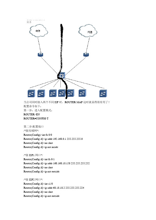
当公司同时接入两个不同ISP时,ROUTER-MAP这时就显得很有用了!配置命令如下:第一步:进入配置模式:ROUTER>ENROUTER#CONFIG T第二步:配置端口/*接局域网*/Router(Config)>int fa 0/0Router(Config-if)>ip addr 192.168.0.1 255.255.255.0Router(Config-if)>no shutRouter(Config-if)>ip nat inside/*接ISP1网口*/Router(Config-if)>int fa 0/1Router(Config-if)>ip addr 168.168.18.158 255.255.255.252Router(Config-if)>no shutRouter(Config-if)>ip nat outside/*接ISP2网口*/Router(Config-if)>int s1/0Router(Config-if)>ip addr 68.18.18.2 255.255.255.224Router(Config-if)>no shutRouter(Config-if)>ip nat outside第三步:设置NAT地址池Router(Config)>Ip Nat Pool Isp1_pool 218.18.18.2 218.18.18.6 Netmask 255.255.255.224 Router(Config)>Ip Nat Pool Isp2_pool 68.18.18.4 68.18.18.10 Netmask 255.255.255.224第四步:设置访问控制列表和NAT转换规则Router(Config)>Access-list 100 permit Ip 192.168.0.0 0.0.0.255 anyRouter(Config)>Ip Nat Inside Source Route-map Isp1 Pool Isp1_poolRouter(Config)>Ip Nat Inside Source Route-map Isp2 Pool Isp2_pool第五步:设置ROUTE MAP规则Router(Config)>Route-map Isp1 Permit 10Router(Config-route-map)>Match Ip address 100Router(Config-route-map)>Match Int Fa 0/1Router(Config)>Route-map Isp2 Permit 10Router(Config-route-map)>Match Ip address 100Router(Config-route-map)>Match Int S1/0第六步:设置浮动静态路由Router(Config)>Ip Route 0.0.0.0 0.0.0.0 168.168.18.157Router(Config)>Ip Route 0.0.0.0 0.0.0.0 68.18.18.1 20第七步:结束并保存配置:Router(Config)>endRouter#Copy Ru St。
route-map

route-map 从浅显到深⼊的理解理解策略路由PBR与路由策略的区别(拒绝知识的复制)今天,这个专题应⽤下route-map,在这个之前,有很多内容需要掌握,不是简单的制定⼀个路由图就可以了。
--------本次专题理论的东西居多,但是不是复制黏贴,是加上⾃⼰的理解思想。
第⼀个要解决的问题:路由策略和策略路由有什么区别?到底为何物?先说策略路由,影响的不是路由表的⽣产,策略路由⼜叫PBR,是Policy-based routing策略基于路由,那么这个路由表存在是已经存在⽽且稳定的。
⽤TCP/IP路由技术⼀书的表述就是:策略路由就是⼀个复杂的静态路由。
总结:策略路由是⼀个基于路由表的影响特定数据包的转发的⼀个⽅式,这个⽅式是应⽤于接⼝下的。
例如:让192.168.1.1的数据包都从s0/1⾛,让192.168.1.2的数据包都从s0/1⾛access-list 1 permit host 192.168.1.1access-list 2 permit host 192.168.1.2route-map ccie permit 10match ip address 1set interface s0/1router0map ccie permit 20match ip address 2set interface s0/2int fa1/0ip policy route-map ccie注意:set interface s0/1 与 set default interface s0/1set ip next-hip 与 set default ip next-hop 是有区别的,前者不查找路由直接进⾏了转发,⽽后者是先查找路由表,查找不到精确的路由表时才会转发到下⼀跳接⼝或IP。
注意:PBR只有进⽅向⽅向,⼀定要注意!PBR优先于路由表查找注意:策略路由PBR默认只对穿越流量⽣效,(config)#(ip local policy route-map ccie) //这样写是策略理由也影响本地产⽣的流量思科利⽤策略路由最常⽤的⽅式是丢弃报⽂:set interface null 0 (这样⽐acl deny 减少很多开销)int null 0no ip unreachable //为了防⽌丢弃报⽂返回⼤量的不可达信息路由策略开始了,路由策略说⽩了就是影响路由表最终⽣成的结果的,⽐如我可以匹配ACL之后修改OSPF⽹络中的COST,达到改变路由表的效果。
双isp网络配置方法

ip http server
no ip http secure-server
!
ip route 0.0.0.0 0.0.0.0 30.1.1.1
control-plane
!
line con 0
logging synchronous
no exec
line aux 0
line vty 0 4
!
!
End
ip virtual-reassembly
ip policy route-map isp2
duplex auto
speed auto
!
interface FastEthernet3/0
ip address 20.1.1.1 255.255.255.0
ip nat outside
ip virtual-reassembly
no service password-encryption
!
hostname Router
!
boot-start-marker
boot-end-marker
!
!
no aaa new-model
!
resource policy
!
memory-size iomem 5
!
!
ip cef
no ip domain lookup
speed auto
!
ip default-gateway 172.16.2.1
ip http server
no ip http secure-server
!
control-plane
line con 0
logging synchronous
双ISP线路出口路由器案例

主要思想是IP-SLA结合EEM来做到无人值守的管控给出R4的关键配置这个题目没什么意义现实中也不会出现·· ISP一般2家不会选同一家,所以流量不会负载均衡···如果是2家可以结合route-map或者静态路由来做才符合环境1 ISP1中出现故障就删除去往ISP1的默认路由同时挂载ACL 过滤192.168.2.0的流量ISP1中故障恢复后放行192.168.2.0的流量恢复默认路由2 ISP2中出现故障就删除去往ISP2的默认路由同时挂载ACL 过滤192.168.2.0的流量ISP2中故障恢复后放行192.168.2.0的流量恢复默认路由全过程无人值守,切换不需要人为干预R4:track 1 ip sla 1 reachability!track 2 ip sla 2 reachability!!!!!!!!!interface FastEthernet0/0ip address 14.1.1.4 255.255.255.0ip nat insidespeed autoduplex auto!interface FastEthernet0/1ip address 34.1.1.4 255.255.255.0ip nat outsidespeed autoduplex auto!interface FastEthernet1/0ip address 24.1.1.4 255.255.255.0ip nat outsidespeed autoduplex auto!interface FastEthernet1/1no ip addressshutdownspeed autoduplex auto!ip nat inside source route-map NAT1 interface FastEthernet0/1 overload ip nat inside source route-map NAT2 interface FastEthernet1/0 overload ip forward-protocol nd!!no ip http serverno ip http secure-serverip route 0.0.0.0 0.0.0.0 34.1.1.3 track 1ip route 0.0.0.0 0.0.0.0 24.1.1.2 track 2ip route 2.2.2.0 255.255.255.0 24.1.1.2ip route 3.3.3.0 255.255.255.0 34.1.1.3ip route 192.168.1.0 255.255.255.0 14.1.1.1ip route 192.168.2.0 255.255.255.0 14.1.1.1!ip sla 1icmp-echo 3.3.3.3 source-interface FastEthernet0/1 threshold 500timeout 999frequency 1ip sla schedule 1 life forever start-time nowip sla 2icmp-echo 2.2.2.2 source-interface FastEthernet1/0 threshold 500timeout 999frequency 1ip sla schedule 2 life forever start-time now access-list 1 permit 192.168.1.0 0.0.0.255access-list 1 permit 192.168.2.0 0.0.0.255!route-map NAT2 permit 10match ip address 1match interface FastEthernet1/0!route-map NAT1 permit 10match ip address 1match interface FastEthernet0/1!!!control-plane!!line con 0exec-timeout 0 0privilege level 15logging synchronousstopbits 1line aux 0exec-timeout 0 0privilege level 15logging synchronousstopbits 1line vty 0 4login!event manager applet TRACK_2_UPevent track 2 state upaction 1.0 cli command "enable"action 2.0 cli command "conf te"action 3.0 cli command "no access-list 100"action 4.0 cli command "interface fa 0/0"action 5.0 cli command "no ip access-group 100 in "action 6.0 cli command "end"event manager applet TRACK_2_DOWNevent track 2 state downaction 1.0 cli command "enable"action 2.0 cli command "conf te"action 3.0 cli command "access-list 100 deny ip 192.168.2.0 0.0.0.255 any " action 3.1 cli command " access-list 100 permit ip any any "action 4.0 cli command " interface fa 0/0 "action 5.0 cli command " ip access-group 100 in "action 6.0 cli command "end"event manager applet TRACK1_1_DOWNevent track 1 state downaction 1.0 cli command "enable"action 2.0 cli command "conf te"action 3.0 cli command "access-list 100 deny ip 192.168.2.0 0.0.0.255 any " action 3.1 cli command " access-list 100 permit ip any any "action 4.0 cli command " interface fa 0/0 "action 5.0 cli command " ip access-group 100 in "action 6.0 cli command "end"event manager applet TRACK_1_UPevent track 1 state upaction 1.0 cli command "enable"action 2.0 cli command "conf te"action 3.0 cli command "no access-list 100"action 4.0 cli command "interface fa 0/0"action 5.0 cli command "no ip access-group 100 in "action 6.0 cli command "end"1111.png(17.24 KB)2015-1-21 00:35在R1左侧的内网接口配置策略路由,当数据包源地址属于192.168.1.0/24时,优先走ISP1,如果ISP1失效走ISP2;当数据包源地址属于192.168.2.0/24时,根据ISP1和ISP2的连通性结果选择路由:当两条ISP线路都正常时走ISP2,这样就躲开了192.168.1.0/24所走的路径(因为它优先走ISP1),实现了流量的负载平衡。
策略路由双出口配置实例

策略路由:双出口配置实例(一)实验拓朴:(二)实验要求:1、R1连接本地子网,R2为边缘策略路由器,R3模拟双ISP接入的Internet环境。
2、要求R1所连接的局域网部分流量走R2-R3间上条链路(ISP1链路),部分流量走R2-R3间下条链路(ISP2链路)从而实现基于源的供应商链路选择和网络负载均衡。
(三)各路由器配置如下:R1#sh run //路由器R1的配置interface Loopback0 //模拟子网一:192.168.1.0/24ip address 192.168.1.1 255.255.255.0 //模拟子网中第一台主机ip address 192.168.1.2 255.255.255.0 secondary //模拟子网中第二台主机!interface Loopback2 //模拟子网二:192.168.2.0/24ip address 192.168.2.1 255.255.255.0ip address 192.168.2.2 255.255.255.0 secondary!interface FastEthernet0/0ip address 12.0.0.1 255.255.255.0!!router rip //通过RIP协议配置网络的连通性version 2network 192.168.1.0network 192.168.1.0network 12.0.0.0R3#sh run //路由器R3的配置Building configurationinterface Loopback0 //模拟一个连接目标description to internetip address 100.100.100.100 255.255.255.0!interface Serial1/1 //模拟ISP1的接入端口ip address 123.0.0.3 255.255.255.0serial restart-delay 0!interface Serial1/3 //模拟ISP2的接入端口ip address 223.0.0.3 255.255.255.0serial restart-delay 0!router ripversion 2network 100.0.0.0network 123.0.0.0network 223.0.0.0no auto-summary!endR2#sh run //策略路由器R2的配置Building configuration...interface FastEthernet0/0ip address 12.0.0.2 255.255.255.0ip policy route-map isp-test //在接口上启用策略路由isp-test进行流量控制duplex half!interface Serial1/1ip address 123.0.0.1 255.255.255.0serial restart-delay 0! bitscn_cominterface Serial1/3ip address 223.0.0.1 255.255.255.0 serial restart-delay 0router ripversion 2network 12.0.0.0network 123.0.0.0network 223.0.0.0no auto-summarylogging alarm informationalaccess-list 101 permit ip 192.168.1.0 0.0.0.255 host 100.100.100.100 //访问控制列表101,用于过滤原地址,允许子网192.168.1.0流量通过*/access-list 102 permit ip 192.168.2.0 0.0.0.255 host 100.100.100.100 //访问控制列表102,用于过滤原地址,允许子网192.168.2.0流量通过*/!route-map isp-test permit 10 //定义route-map,取名为isp-test,序列为10match ip address 101 //检查源地址,匹配acl 101set ip default next-hop 123.0.0.3 //指定下一跳地址!route-map isp-test permit 20 //定义isp-test的第二条语句,序列号为20 match ip address 102 //检查源地下,匹配acl102set ip default next-hop 223.0.0.3!route-map isp-test permit 30 //定义isp-test的第三条语句,序列号为30 set default interface Null0 //丢弃不匹配规定标准的包end(四)调试R2#sh ip policy //显示应用的策略Interface Route mapFa0/0 isp-accR2#sh route-map isp-test //显示配置的路由映射图route-map isp-test, permit, sequence 10Match clauses:ip address (access-lists): 101Set clauses:ip default next-hop 123.0.0.3Policy routing matches: 0 packets, 0 bytesroute-map isp-test, permit, sequence 20Match clauses:ip address (access-lists): 102Set clauses:ip default next-hop 223.0.0.3Policy routing matches: 0 packets, 0 bytesroute-map isp-test, permit, sequence 30 Match clauses:Set clauses:default interface Null0Policy routing matches: 0 packets, 0 bytesR1#traceroute //路由跟踪Protocol [ip]: //ip流量Target IP address: 100.100.100.100 //目标地Source address: 192.168.1.1 //源地址为子网一的第一台主机Numeric display [n]:Timeout in seconds [3]:Probe count [3]:Minimum Time to Live [1]:Maximum Time to Live [30]:Port Number [33434]:Loose, Strict, Record, Timestamp, Verbose[none]:Type escape sequence to abort.Tracing the route to 100.100.100.1001 12.0.0.2 72 msec 216 msec 276 msec2 123.0.0.3 288 msec 360 msec * //ISP1入口R1# tracerouteProtocol [ip]:Target IP address: 100.100.100.100Source address: 192.168.1.2 //源地址为子网一的第二台主机Numeric display [n]:Timeout in seconds [3]:Probe count [3]:Minimum Time to Live [1]:Maximum Time to Live [30]:Port Number [33434]:Loose, Strict, Record, Timestamp, Verbose[none]:Type escape sequence to abort.Tracing the route to 100.100.100.1001 12.0.0.2 92 msec 188 msec 52 msec2 123.0.0.3 416 msec 436 msec * //ISP1入口----------------------------------------------------------------------------------R1#tracerouteProtocol [ip]:Target IP address: 100.100.100.100Source address: 192.168.2.1 //源地址为子网二的第一台主机Numeric display [n]:Timeout in seconds [3]:Probe count [3]:Minimum Time to Live [1]:Maximum Time to Live [30]:Port Number [33434]:Loose, Strict, Record, Timestamp, Verbose[none]:Type escape sequence to abort.Tracing the route to 100.100.100.1001 12.0.0.2 136 msec 40 msec 144 msec2 223.0.0.3 356 msec * 132 msec //ISP2入口---------------------------------------------------------R1#tracerouteProtocol [ip]:Target IP address: 100.100.100.100 Source address: 192.168.2.2 //源地址为子网二中第二台主机Numeric display [n]:Timeout in seconds [3]:Probe count [3]:Minimum Time to Live [1]:Maximum Time to Live [30]:Port Number [33434]:Loose, Strict, Record, Timestamp, Verbose[none]:Type escape sequence to abort.Tracing the route to 100.100.100.1001 12.0.0.2 28 msec 104 msec 200 msec2 223.0.0.3 300 msec * 196 msec //ISP2入口-----------------------------------------------------(五)小结:通过以上实验,可以看到子网一(192.168.1.0/24)的流量都经过R2-R3的上一条链路选择了ISP1链路,子网二(192.168.2.0/24)的流量都经过R2-R3的下一条链路选择了ISP2链路。
双ISP配置实验:包括负载均衡+冗余备份

ip address 200.200.2.253 255.255.255.0 ip nat outside int s1 ip address 200.200.1 .253 255.255.255.0 ip nat outside ip nat pool isp1_pool 200.200.10.1 200.200.10.250 netmask 255.255.255.0 ip nat pool isp2_pool 200.200.20.1 200.200.20.250 netmask 255.255.255.0 ip nat inside source route- map isp1 poo l isp1_pool ip nat inside source route- map isp2 pool isp2_pool ip route 200.168.1.0 255.255.255.0 200.200.2.254 ip route 200.168.2.0 255.255.255.0 200.200.2.254 ip route 200.168.3.0 255.255.255.0 200.200.2.254 ip route 201.168.1.0 255.255.255.0 200.200.1 .254 ip route 201.168.2.0 255.255.255.0 200.200.1.254 ip route 201.168.3.0 255.255.255.0 200.200.1.254 ip route 0.0.0.0 0.0.0.0 200.200.2.254 ip route 0.0.0.0 0.0.0.0 200.200.1.254 access -list 1 permit 192.168.0.0 0.0.0.255 access -list 2 permit 200.200.1 .254 access -list 3 permit 200.200.2.254 route- map isp2 permit 10 match ip address 1 match ip next- hop 3 ! route- map isp1 permit 10 match ip address 1 match ip next- hop 2 ! 以上是关键的配置。另 外 , 即使添加了 set interface语句仍然可以成功, 但是确是多余的配置 , 无用功。 route- map isp2 permit 10 match ip address 1 match ip next- hop 3 set interface Serial0 ! route- map isp1 permit 10 match ip address 1 match ip next- hop 2 set interface Serial1 配置中的映射表还可以配置为 , 需要注意m a t ch interface 表 示 的 使 出 站 接 口, 而非入站接口。 route- map isp2 permit 10 match ip address 1 match interface Serial0 !
RCNP考试(习题卷7)

RCNP考试(习题卷7)第1部分:单项选择题,共76题,每题只有一个正确答案,多选或少选均不得分。
1.[单选题]配置策略路由时,会用到route-map语句,在route-map语句中缺省最后隐含有一条deny any的语句,该语句能达到的目的()。
根本不存在这条隐含语句A)没有匹配前面的permit语句的数据会匹配该语句,查找常规路由B)没有匹配前面的permit语句的数据会匹配该语句,被丢弃C)没有匹配前面的permit语句的数据不会匹配该语句答案:A解析:2.[单选题]锐捷交换机,使用 spanning-tree 命令,这时候启动的是( )A)STPB)RSTPC)MSTP答案:C解析:3.[单选题]在以下OSPF特殊区域中,ABR不会自动生成默认路由,必须手工向该区域内部通告默认路由的是()A)NSSAB)完全stub区域C)stub区域答案:A解析:4.[单选题]常见的ARP欺骗工作在()。
A)传输层B)数据链路层C)网络层D)应用层答案:C解析:5.[单选题]OSPF 的路由器,有一个接口属于区域 0,一个接口属于区域 1,并且重分布了 1条静态路由,则该路由器一定会产生的 LSA 类型是( )A)type1 type3 type5B)type1 type2 type3C)type2 type3 type5D)type1 type3 type5 type7答案:A解析:6.[单选题]()当客户网指是单出口设备多线路时(有电信、教育网,联通三条出口线路),以下哪个方法无法实观分流设计()A)在出口设备上通过设置策略精由,将某些源IP的数据包强制转发到出口设备连接联通线路的接口上,配器默认路由到电信,配置明细路由到教育网B)配置三条默认路由分别指向三个不同出口C)在出口设备上通过设置不同的明细静态路由以实现的据分流。
例如将教育网和联通的明细路由都配置出来,再配置一条默认路由指向电信出口D)在为某些源IP地址做基于策略数据分流时,将访问教育网的数据转发到出口设备的教育网线路上,将访问公网的数据转发到出口设备的联通线线路上,配置默认踏由指向电信答案:B解析:7.[单选题]管理员在一台锐捷交换机上启用 802.1D 生成树后, 过 show spanning-tree 命令进行查看 通时发现端口状态为 listening。
第十五章 route-map的配置

4
ROUTE-MAP语句设计 语句设计
routemyroute-map my-map permit 10 {match statements} {set statements} RoutemyRoute-map my-map deny 20 {match statements} {set statements}
注意如果没有30这条允许语句将怎么样? 注意如果没有30这条允许语句将怎么样? 30这条允许语句将怎么样
9
PBR:policy based route( : ( 基于策略的路由与route-map的结合应用 的结合应用-------4 基于策略的路由与 的结合应用
PBR与一般路由协议比如静态路由,RIP路由的区别 PBR与一般路由协议比如静态路由,RIP路由的区别 与一般路由协议比如静态路由,RIP PBR可以使得路由基于源地址来转发 可以使得路由基于源地址来转发; PBR实现路由策 PBR可以使得路由基于源地址来转发; 但PBR实现路由策 需要通过调用Route map来实现 Route来实现。 略,需要通过调用Route-map来实现。 一般IP IP路由是基于目标网络或地址来进行路由转发 一般IP路由是基于目标网络或地址来进行路由转发
将匹配访问控 制列表23 23、 制列表23、29 的地址的路由 更新设置成类 型1且度量值为 500
8
路由器上的关于Route-map的配置 的配置 路由器上的关于
-2和访问控制列表37匹来自的路由更新包不能重分发到OSPF区域 和访问控制列表37匹配的路由更新包不能重分发到OSPF区域 37匹配的路由更新包不能重分发到OSPF
第十六章 ROUTE-MAP的使用 的使用
ROUTE-MAP使用的场合 使用的场合
关于NAT+双出口的两种配置

关于NAT+双出⼝的两种配置⽬的:模拟拥有双出⼝链路情况下基于原地址策略路由功能,实现不同原内部地址从不同出⼝对外部⽹络的访问,由于多数实际情况下路由器在外部端⼝使⽤NAT对内⽹地址进⾏翻译,所以本试验也使⽤双NAT对内部地址进⾏翻译,实现通过多ISP访问Internet功能。
环境描述:使⽤设备为Cisco2621XM + NE-1E模块,该配置拥有两个FastEthernet以及⼀个Ethernet端⼝。
现使⽤Ethernet 1/0 端⼝连接内部局域⽹,模拟内部拥有100.100.23.0 255.255.0.0 与100.100.24.0 255.255.0.0 两组客户机情况下基于原地址的策略路由。
Fastethernet 0/0 模拟第⼀个ISP接⼊端⼝,Fastethernet 0/1模拟第⼆个ISP接⼊端⼝,地址分别为 Fastethernet 0/0 的ip地址192.168.1.2 255.255.255.0 对端ISP地址192.168.1.1 255.255.255.0 Fastethernet 0/1 的ip地址192.168.2.2 255.255.255.0 对端ISP地址192.168.2.1 255.255.255.0通过策略路由后对不同原地址数据流量进⾏分流,使得不同原地址主机通过不同ISP接⼝访问Internet,并为不同原地址主机同不同NAT地址进⾏转换。
具体配置:hostname Routerinterface FastEthernet0/0 --------------------假设该端⼝为ISP 1接⼊端⼝ip address 192.168.1.2 255.255.255.0 --------分配地址ip nat outside --------指定为NAT Outside端⼝no shutinterface FastEthernet0/1 --------------------假设该端⼝为ISP 2接⼊端⼝ip address 192.168.2.2 255.255.255.0 --------分配地址ip nat outside --------指定为NAT Outside端⼝no shutinterface Ethernet1/0 --------------------假设该端⼝为内部⽹络端⼝ip address 100.100.255.254 255.255.0.0 --------分配地址ip nat inside --------指定为NAT Inside端⼝ip policy route-map t0 --------在该端⼝上使⽤route-map t0进⾏策略控制ip nat inside source list 1 interface FastEthernet0/0 overload ------Nat转换,指定原地址为100.100.23.0的主机使⽤Fastethernet 0/0的地址进⾏转换ip nat inside source list 2 interface FastEthernet0/1 overload ------Nat转换,指定原地址为100.100.24.0的主机使⽤Fastethernet 0/1的地址进⾏转换ip route 0.0.0.0 0.0.0.0 192.168.2.1 ------静态路由,对Internet的访问通过192.168.2.1(ISP2)链路ip route 0.0.0.0 0.0.0.0 192.168.1.1 ------静态路由,对Internet的访问通过192.168.1.1(ISP1)链路access-list 1 permit 100.100.23.0 0.0.0.255 ----访问控制列表1,⽤于过滤原地址,允许100.100.23.0⽹段主机流量通过access-list 2 permit 100.100.24.0 0.0.0.255 ----访问控制列表2,⽤于过滤原地址,允许100.100.23.0⽹段主机流量通过route-map t0 permit 10 ----定义route-map t0,permit序列为10match ip address 1 ----检查原地址,允许100.100.23.0 ⽹段地址set interface FastEthernet0/0 ----指定出⼝为Fastethetnet 0/0route-map t0 permit 20 ----定义route-map t0,permit序列为20match ip address 2 ----检查原地址,允许100.100.24.0 ⽹段地址set interface FastEthernet0/1 ----指定出⼝为Fastethetnet 0/1察看路由表Router#show ip routeCodes: C - connected, S - static, I - IGRP, R - RIP, M - mobile, B - BGPD - EIGRP, EX - EIGRP external, O - OSPF, IA - OSPF inter areaN1 - OSPF NSSA external type 1, N2 - OSPF NSSA external type 2E1 - OSPF external type 1, E2 - OSPF external type 2, E - EGPi - IS-IS, su - IS-IS summary, L1 - IS-IS level-1, L2 - IS-IS level-2ia - IS-IS inter area, * - candidate default, U - per-user static routeo - ODR, P - periodic downloaded static route100.0.0.0/16 is subnetted, 1 subnetsC 100.100.0.0 is directly connected, Ethernet1/0C 192.168.1.0/24 is directly connected, FastEthernet0/0C 192.168.2.0/24 is directly connected, FastEthernet0/1S* 0.0.0.0/0 [1/0] via 192.168.1.1[1/0] via 192.168.2.1发现静态路由存在两条路径!察看ip Nat translationsRouter#sho ip nat translationsPro Inside global Inside local Outside local Outside globalicmp 192.168.1.2:1024 100.100.23.23:1024 1.1.1.1:1024 1.1.1.1:1024icmp 192.168.2.2:1280 100.100.24.23:1280 1.1.1.1:1280 1.1.1.1:1280由于路由器外部存在1.1.1.1的地址,⽤于模拟Internet公⽹地址,发现不同⽹段内部主机流量确实已经从不同出⼝访问外部资源,并且使⽤了不同Nat进⾏地址转换!注:⼤部分多ISP情况下都要使⽤NAT地址转换功能,但有些特殊情况下不需使⽤NAT功能,如果不是⽤NAT,就将配置中的有关NAT的配置去掉,如此配置中去掉 ip nat inside source list 1 interface FastEthernet0/0 overload 和ip nat inside source list 2 interface FastEthernet0/1 overload以及在端⼝上去掉ip Nat outside和ip nat inside的配置,就可以实现不⽤NAT的策略路由。
双链路冗余

版权声明:原创作品,允许转载,转载时请务必以超链接形式标明文章原始出处、作者信息和本声明。
否则将追究法律责任。
/247606/94114Cisco双ISP线路路径优化备份冗余之单路由器解决方案通过双ISP(如:一条电信、一条网通)链路可实现网络路径优化、负载均衡及备份冗余,以前本人一直认为Cisco不能实现单路由器双ISP链路的冗余备份,后经过多次测试,发现通过SLA(服务水平)+route-map完全可以实现,在这里愿意和大家一起分享。
网络拓朴:实验任务:●∙∙ PC1/PC2到1.1.1.1流经ISP1,PC1/PC2到2..2.2.2流经ISP2●∙∙ 通过SLA+Route-map实现网络路径优化、负载分担、备份冗余环境描述:●∙∙ 3台Cisco3640 + NE-4E模块,该配置拥有4个Ethernet、2台PC ●∙∙ ISP1、ISP2分别模拟两个不同ISP(internet服务提供商)●∙∙ ISP1 loopback1:1.1.1.1/24、ISP2 loopback1:2.2.2.2/24用来测试●∙∙ R1作为企业边界路由器e0/0、e0/1、分别连接ISP1、ISP2地址分配:详细配置:1、IP地址设置ISP1 (config) #int e0/2ISP1 (config-if) #ip add 192.168.2.1 255.255.255.0ISP1config-if) #no shutdownISP1(config)# int e0/0ISP1 (config-if) #ip add 192.168.0.2 255.255.255.0ISP1config-if) #no shutdownISP1(config)# int lo1ISP1 (config-if) #ip add 1.1.1.1 255.255.255.0ISP1(onfig-if) #no shutdown………………………………………………………………………….ISP2 (config) #int e0/2ISP2 (config-if) #ip add 192.168.2.2 255.255.255.0ISP2 (onfig-if) #no shutdownISP2(config)# int e0/1ISP2 (config-if) #ip add 192.168.1.2 255.255.255.0ISP2config-if) #no shutdownISP2(config)# int lo1ISP2 (config-if) #ip add 2.2.2.2 255.255.255.0ISP2 (config-if) #no shutdown……………………………………………………………………………R1 (config) #int e0/0R1 (config-if) #ip add 192.168.0.1 255.255.255.0R1 (config-if) #no shutdownR1 (config)# int e0/1R1 (config-if) #ip add 192.168.1.1 255.255.255.0R1 (config-if) #no shutdownR1 (config)# int e0/2R1 (config-if) #ip add 192.168.20.1 255.255.255.0R1 (config-if) #no shutdown2、定义相关ACLR1(config)#ip access-list extended all-net ……………………匹配所有R1(config-ext-nacl)#permit ip any anyR1(config)#access-list permit 1 192.168.0.2…………匹配ISP1 next-hopR1(config)#access-list permit 2 192.168.1.2…………匹配ISP2 next-hop3、Route-map、NatR1(config)#route-map isp1-line permit 10R1(config-route-map)#match ip address all-netR1(config-route-map)#match ip next-hop 1……………….匹配ACL 1(关键)R1(config)#route-map isp2-line permit 10R1(config-route-map)#match ip address all-netR1(config-route-map)#match ip next-hop 2……………….匹配ACL 2(关键)R1(config)# ip nat inside source route-map isp1-line int e0/0overloadR1(config)# ip nat inside source route-map isp2-line int e0/1overload4、IP SlA、rtr/track本地路由设备到ISP中间往往连接一个光电转换器(Layer2),当对端shutdown状态,本地设备仍处于UP,这时将导致所谓的“黑洞”现象,我们可以通过SLA来做网络端到端的可用性监测,从而解决这个问题。
双ISP

企业双ISP接入,实现负载分担,冗余,故障检测和自动切换需求:不同vlan的可以按要求走不同的isp从而分担流量,当一个isp故障,可以迅速检测并且自动切换到另外一个isp。
基本思路:策略路由结合track,sla实现;路由配置如下,其他略(*由于和isp之间通常会有光电转换,所以无法直接发现对方接口故障,使用SLA ping来测试对方isp是否故障)ip sla monitor 10type echo protocol ipIcmpEcho 100.1.1.1 source-ipaddr 100.1.1.2timeout 800frequency 1ip sla monitor schedule 10 life forever start-time now (*SLA探测)ip sla monitor 20type echo protocol ipIcmpEcho 200.1.1.1 source-ipaddr 200.1.1.2timeout 800frequency 1ip sla monitor schedule 20 life forever start-time now (*SLA探测)!track 1 rtr 10 reachability(*调用SLA)!track 2 rtr 20 reachability(*调用SLA)!interface FastEthernet0/0ip address 100.1.1.2 255.255.255.252ip nat outsideip virtual-reassemblyduplex autospeed auto!interface FastEthernet1/0ip address 200.1.1.2 255.255.255.252ip nat outsideip virtual-reassemblyduplex autospeed auto!interface FastEthernet2/0ip address 192.168.200.2 255.255.255.252ip nat insideip virtual-reassemblyip policy route-map pbrduplex autospeed auto!router ospf 100log-adjacency-changesnetwork 192.168.200.0 0.0.0.3 area 0default-information originate metric 100!ip http serverno ip http secure-serverip route 0.0.0.0 0.0.0.0 100.1.1.1 track 1(*利用rtr 跟踪,及时调整默认路由)ip route 0.0.0.0 0.0.0.0 200.1.1.1 track 2(*利用rtr 跟踪,及时调整默认路由)!!ip nat inside source route-map isp1 interface FastEthernet0/0 overloadip nat inside source route-map isp2 interface FastEthernet1/0 overload!!ip access-list extended vlan10permit ip 192.168.1.0 0.0.0.255 anyip access-list extended vlan20permit ip 192.168.2.0 0.0.0.255 anyaccess-list 10 deny 100.1.1.2 (*防止自己用来探测的数据被nat)access-list 20 deny 200.1.1.2 (*防止自己用来探测的数据被nat)!route-map isp2 deny 5match ip address 20 (*防止自己用来探测的数据被nat)!route-map isp2 permit 10match interface FastEthernet1/0!route-map isp1 deny 5match ip address 10 (*防止自己用来探测的数据被nat)!route-map isp1 permit 10match interface FastEthernet0/0!route-map pbr permit 10match ip address vlan10set ip next-hop verify-availability 100.1.1.1 1 track 1(*根据下一跳的可达性,转发数据)!route-map pbr permit 20match ip address vlan20set ip next-hop verify-availability 200.1.1.1 2 track 2(*根据下一跳的可达性,转发数据)!route-map pbr permit 30set interface Null0(*除了vlan 10,20的流量其他的直接丢弃,因为如果不做,那么策略路由不处理,按路由表将转发,虽然没有nat,isp会丢弃,但是浪费路由器资源;不过这些策略路由如果没特殊需求可以不做,路由器本身默认路由就已经实现负载均衡了)。
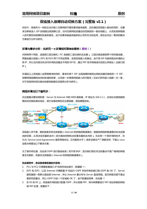
双线接入故障自动切换方案--完整版_v2.1 _new
常用网络项目案例
R1: interfaceFastEthernet0/0 ipaddress202.1.1.1255.255.255.0 ipnatoutside ! interfaceFastEthernet1/0 ipaddress192.168.1.2255.255.255.0 ipnatinside ! routerospf110 router-id1.1.1.1 network202.1.1.00.0.0.255area1 iproute10.1.1.0255.255.255.0192.168.1.1 iproute10.1.2.0255.255.255.0192.168.1.1 !
常用网络项目案例
测试:
在 SW 上的路由表中的默认路由见下面:
棕鹰
原创
在 SW 上做 ping 100.1.1.1 测试,然后查看线路切换效果:
当手动地将首选的那条路给断开后(在由经的 R4 的接口 0/0 上做) ,可以看出,由于线路断开,SW 上配 置的主线路的 sla 马上就探测到网络不通,sla 将监控的状态变为 down,此时网络会暂时的中断,但很快 的路由就切换了,走另一条路,网络恢复畅通;接着将 R4 的接口变为 up,SW 上配置的 sla 马上就探测 到主线路网络畅通, 此时浮动路由状态切换, 路由恢复成原状, 在切换的过程中网络同样会有短暂的中断, 很快地就恢复了! OK! sla 技术探测网络的简单按例就此完成! 下面用另一种基于 route-map 的方式来完成对双线的探测与 策略路由(按规定的路径进行路由,优先于路由表的查找处理) :
常用网络项目案例
棕鹰
原创
双线接入故障自动切换方案(完整版 v2.1)
双isp接入,防火墙activeactivefailover加非对称路由问题的解决(精)

双isp接入,防火墙active/active failover加非对称路由问题的解决有一家企业,对外提供服务,客户遍布全国,客户可能使用电信链路,可能使用网通链路,所以这家企业申请了两条链路,一条电信,一条网络,希望客户选择合适的链路来访问服务。
使用了两台cisco防火墙分别连接电信和网通。
后面连接整个内部网络,对外提供服务的服务器也在其中。
原则:1.两条链路能够使用同时使用2.外部用户(不管使用哪条链路),都能正确访问注:大体上是需要从哪条链路进来的数据包,返回的数据包也要从这条链路回去。
在防火墙上,非对称路由很可能会有问题的。
3.如果能做到负载均衡那更加好。
方法考虑:1.active/standby failover两条链路配置在不同的防火墙上面(接口ip地址不一样),而a/s failover要求两台防火墙配置一样,所以这个方案行不通。
其中一台配置配置成active,两条链路同时接在上面,另外一台standby。
这样的配置问题有很多:一台防火墙上面不能同时配置两条默认路由;即使其中一条链路写了明晰路由(如把网通主要的的路由写出来),在一台防火墙上面,也涉及到非对称路由的问题;方案1完全否决2.active/active failover两条链路可以同时使用,而且可以接在不同的防火墙上面。
因为两台防火墙各有两个context(虚拟防火墙),这四台防火墙两两互备,可以实现负载均衡。
而且使用了2对虚拟防火墙,两对虚拟防火墙配置独立,这样就有两套路由表,所以在上面分别写默认路由一点问题都没有,默认路由问题解决。
似乎这个方式很好,但是还有一个问题没有解决,那就是非对称路由的问题。
从虚拟防火墙1进来的数据包,进入到内网,返回的时候,如果经过了虚拟防火墙2,这个时候如果是tcp 数据包,那因为这不是一个syn数据包,那2就可能丢弃掉这个数据包。
在负载均衡上面做的不错,但是非对称路由没有解决,需要再改进,不然还是不能解决问题3.防火墙独立使用加链路负载均衡设备两台防火墙各接一条链路,然后都接到一台链路负载均衡设备上面去。
- 1、下载文档前请自行甄别文档内容的完整性,平台不提供额外的编辑、内容补充、找答案等附加服务。
- 2、"仅部分预览"的文档,不可在线预览部分如存在完整性等问题,可反馈申请退款(可完整预览的文档不适用该条件!)。
- 3、如文档侵犯您的权益,请联系客服反馈,我们会尽快为您处理(人工客服工作时间:9:00-18:30)。
双ISP接入route-map实现奇偶分流
双ISP接入route-map实现奇偶分流
项目实践
2811路由器有两根外线接入,一根光纤和一条ADSL 。
要实现这两条线路能同时使用,达到分流的效果。
具体配置如下:
cisco2811#sh run
Building configuration...
Current configuration : 4386 bytes
!
version 12.4
service timestamps debug datetimemsec
service timestamps log datetimemsec
no service password-encryption
!
hostname cisco2811
!
boot-start-marker
boot-end-marker
!
logging buffered 51200 warnings
enable password changhang
!
noaaa new-model
!
!
ipcef
no ipdhcp use vrf connected
ipdhcp excluded-address 192.168.1.1 192.168.1.30
!
ipdhcp pool pool1
network 192.168.1.0 255.255.255.0
default-router 192.168.1.1
dns-server 202.96.128.86
!
!
interface FastEthernet0/0 ---光纤接入
ip address 121.22.11.209 255.255.255.248
ipnat outside
ip virtual-reassembly
duplex auto
speed auto
!
interface FastEthernet0/1 ---ADSL接入
no ip address
iptcp adjust-mss 1442
duplex auto
speed auto
pppoe-client dial-pool-number 1
!
interface FastEthernet0/0/0 ---局域网接口
ip address 192.168.1.1 255.255.255.0
ipnat inside
ip virtual-reassembly
duplex auto
speed auto
!
interface Dialer1
mtu 1492
ip address negotiated
ipnat outside
ip virtual-reassembly
encapsulation ppp
dialer pool 1
dialer-group 1
ppp authentication pap callin
ppp pap sent-username password 0 ******
!
ip route 0.0.0.0 0.0.0.0 Dialer1
ip route 0.0.0.0 0.0.0.0 121.22.11.214
!
!
ip http server
ip http authentication local
ip http timeout-policy idle 60 life 86400 requests 10000
!
ipnat inside source route-map isp1 interface FastEthernet0/0 overload ipnat inside source route-map isp2 interface Dialer1 overload
!
access-list 101 permit ip 192.168.1.0 0.0.0.254 any
access-list 102 permit ip 192.168.1.1 0.0.0.254 any
dialer-list 1 protocol ip permit !
route-map isp2 permit 10
match ip address 102
set interface Dialer1
!
route-map isp1 permit 10
match ip address 101
set interface FastEthernet0/0
!
!
line con 0
exec-timeout 60 0
logging synchronous
login
line aux 0
line vty 0 4
privilege level 15
password ******
login local
transport input all
line vty 5 15
privilege level 15
login local
transport input telnet
!
scheduler allocate 20000 1000
!
end。
