是德科技keysight n9322c基础频谱分析仪说明书使用手册技术指标,原安捷伦agilent
频谱分析仪和信号源使用说明

一、注意事项:1、测试信号时一般需要在频谱仪上接一个转换头,注意将转换头的螺纹和频谱仪的螺纹对齐再用力拧,否则容易将螺纹损坏。
(安装和拆卸转换头时需要注意)2、测试大于30dBm的大功率信号时,最好先加上衰减器在进行测试,以免功率过大将频谱仪烧坏。
二、常用功能介绍:频谱仪左边是显示屏,右边是操作按键。
左下角是开关。
右边的操作按键分为5个部分:FUNCTION、MARKER、SYSTEM、CONTROL、DATA ENTRY。
当选择某个按键时,在显示屏的右侧会出现相应的菜单选项,通过按旁边的键可以选择对应的操作。
下面分别介绍各部分常用的操作选项。
1、FUNCTIONFrequency->Center:设置中心频率;Frequency->Start:设置起始频率;Frequency->Stop:设置终止频率;Frequency->CF Step:设置频率步进值;Span->WidthSpan:Span->FullSpan:设置全屏显示的频率跨度;AmpL->Ref.Lever:设置参考频率;Measure->Adjacent CH Power:相邻信道功率(可通过旋钮测试主瓣和旁瓣信号的带宽和带内功率);Measure->Channel Power:信道功率;Measure->Occupied BandWith:占用带宽;Measure->Harmonic Distortion:谐波失真;2、MARKERPEAK:该键最常用,用来标记输入信号峰值功率;3、SYSTEM该部分用来进行系统设置,如将测试图像保存为图片格式,从软盘读取文件等。
由于软盘不常用,所以一般用相机直接拍摄当前的图像。
Preset:将系统恢复到默认状态;4、CONTROLTrace->Clr&Wrt:清除当前显示;Trace->Max Hold:保留最大值;Trace->Min Hold:保留最小值;CPL->All Auto:所有的设为自动;CPL->RBW:设置分辨率带宽(该值越小,分辨率越高,相应扫描速率越慢);CPL->VBW:设置显示带宽;CPL->Swp Time:扫频时间;(一般RBW和VBW设置为自动;Swp Time保持默认值)5、DA TA ENTRY该部分用来输入数值。
Keysight Technologies FieldFox 电缆和天线分析仪技术概述说明书

N9912A N9913A N9914A N9915A N9916A N9917A N9918AKeysight TechnologiesFieldFox Cable and Antenna Analyzers4/6/6.5/9/14/18/26.5 GHzTechnical OverviewEvery piece of gear in your kit had to prove its worth. Measuring up and earning a spot is the driving idea behind Keysight Technologies, Inc.’s FieldFox analyzers. It starts with adaptability: every operating mode is flexible enough to meet the needs of novices and experts alike. To accelerate your work, each mode has a task-driven interface that saves time in the field. Best of all, FieldFox is designed to withstand your toughest working conditions.FieldFox is ideal for performing cable and antenna (CAT) measurements. Key CAT measurements include:–Distance-to-fault, return loss, VSWR, and cable loss (1-port and 2-port) –Integrated QuickCal - no calibration kit required–4/6/6.5/9/14/18/26.5 GHz Step up to FieldFox -- and achieve more in the field.Boost your readiness FieldFox–Ready to sweep the line at power on (CalReady)–Working in the dusk or rain–Screen is clearly viewable under direct sunlight–Easy file transfer between FieldFox and PC–Datalink Software provides simple and easy reporting–Future proof with software licensing upgradeConvenient side strap makes it easyTask-driven keys are grouped to easily perform fieldmeasurementsPortrait design and large buttons for easy operation – even with gloves onDedicated marker function access11.5”(292 mm)7.4”(188 mm)(N9912A 4/6 GHz)Convenient side strap makes it easyTask-driven keys are grouped to easily perform fieldmeasurementsPortrait design and large buttons for easy operation – even with gloves onDedicated marker function access11.5”(292 mm)7.4”(188 mm)N9913A/14A/15A/16A/17A/18A…and depend on its durability and convenienceLEFT SIDERIGHT SIDESimplify interference analysis with AM/FM tune and listenBuilt-in DC supply for powering external bias-tees, probes, and active devicesKeep going with field-swappablebatteries that last up to 3 1/2hoursports from moistureSpectrum analyzer 25 MHz IF out usable SD flash card for data storageUSB ports for easy data storageexternal trigger outputand SCPI porgrammingTOPPort 1/RF outputConnector bay protects RF connectorsGet precise location using the built-in GPS receiverExternal reference and Port 2/SA RF inputQuick connect shoulder strap clipsCable and antenna analyzerFifty to sixty percent of microwave-link equipment issues are related to cables, antennas and connectors. Degraded feeder lines cause poor coverage, link failures, and reduced sensitivity on the receive path.To maintain the quality of a RF/MW link,it is critical to keep the cable and antenna systems in good working condition.Use FieldFox to make return loss, VSWR, insertion loss, 1-port cable loss, and distance-to-fault measurements. You can test antennas, cables, filters, and amplifiers with a single instrument. The amplifiers can be biased using FieldFox’s built-inDC source.Distance to faultWhen the return loss of any given feeder line system, including the antenna, failsto meet specification, the next step isto find which part of the system failed. The distance to fault measurement or DTF is used to transfer frequency domain measurements to distance domain. This helps the user locate the discontinuity in feeder line.FieldFox can make both return loss and distance-to-fault measurements at the same time. This helps you correlate overall system degradation with specific faults inthe cable and antenna system. The built-incable editor allows you to edit existingcable types on-site, and save them as newcable types with user defined names.Return loss/VSWRmeasurementsReturn loss /VSWR is the single mostimportant parameter to measure andverify a cable and antenna system. Thismeasurement reflects the power transferefficiency of a given system. It combineswith the distance-to-fault measurement, tohelp users quickly identify where the faultyRF components are.View and control the RL and DTF displays independentlyVSWR measurementCable and antenna analyzer measurementsFieldFox’s waveguide distance-to-fault measurement Cable loss measurement (1-port)If RF and microwave cables have beeninstalled on a tower or a building, likea distributed antenna system (DAS), itbecomes difficult to measure cable lossby accessing both ends of the cableunder test. FieldFox allows users to makesingle-port cable-loss measurements withhigher accuracy close to the insertionloss measurement and provides a higherdynamic range for longer cables.One-port cable loss measurementCable and antenna measurementsInsertion lossThe insertion loss measurementcharacterizes the loss of a jumper cable,feeder cable, a connector, or an attenuatorif both ends are accessible. It can alsomeasure the filter type of devices likediplexer, duplexer, tower mounted amplifier(TMA), low noise amplifier (LNA) and bi-directional amplifier (BDA) etc. For amplifiermeasurements, it measures gain instead ofloss of the device.Insertion loss displayWaveguide measurementsThe Waveguides are widely used toprovide transmission links betweenmicrowave transmitters and antennas, aswaveguides have less loss than coax. Dueto the dispersion nature of a waveguide,it is always a challenge to figure out thevelocity factor (VF) of a particular typeof waveguide in DTF (distance-to-fault)measurements. FieldFox can help youautomatically calculate waveguide VF whenthe waveguide type is chosen.CalReady – calibrated at power on, ready to goSave time and get right to work withFieldFox’s CalReady feature. With CalReady, the analyzer is already calibrated and ready to make measurements such as return loss, VSWR, 1-port cable loss, and DTF measurements without having to connect/ disconnect additional calibration devices.Hassle-free calibration in the ield with the industry’s irst and only QuickCalFieldFox is the industry’s first and only handheld network analyzer with a built-in calibration capability that allows you to calibrate the network analyzer without carrying a calibration kit (cal kit) into the field. With any other test instrument, when you add additional devices to the test port, such as jumper cables or adapters, you need to recalibrate using a cal kit. QuickCal eliminates the need to carry and use a cal kit, and also provides worry-free accuracy. FieldFox’s QuickCal supports measurements such as insertion loss/gain, 1-port cable loss, return loss, and DTF.Mechanical calibrationFieldFox supports a wide selection of mechanical calibration kits, such as T cal kits for various frequency ranges. You also CalibrationBroadband CalFieldFox allows you to make broadband calibrations, which means the instrument is calibrated over the maximum frequency range. After a broadband calibration, you can change the frequency range or number of points without recalibrating the instrument. The calibration is interpolated, and accuracy is maintained.Fast and accurate calibration with ECalThe FieldFox calibration engine supports Keysight’s USB ECal modules. ECal support reduces calibration time and the need to make multiple connections during testing, while also providing for greater consistency between measurements. For FieldFox users, that translates into fewer human errors and increased accuracy.Waveguide calibrationKeysight offers both high-performance and also economical waveguide calibration kits. The economical kits (N9911X) are ideal for field maintenance and troubleshooting, as they provide good measurement results atlower costs.FieldFox’s QuickCal allows you to perform calibrations without carrying a cal kitSTEP 1STEP 2STEP 3Keysight N9911x economicalCarry FieldFox wherever you need to go–Kit friendly 3.0 kg or 6.6 lbs–Large buttons are easy to operate, even when wearing gloves–Field swappable battery lasts up to 4 hours–Non-slip rubber grip securely fits in your hands and won’t slide off the hood of your vehicle–Vertical “portrait” orientation makes it easy to hold and operate at the same timeLarge buttons make it easy to perform spectrum analysis measurements – even with gloves onDesigned for you and the work you do everydayRugged enough to meet MIL-specs –Completely sealed instrument enclosureprovides measurement stability in harshenvironments–Specially designed connector bay protects RF connectors from damage due to drops or other external impacts (designed to withstand 4’ drop on concrete surface on all 6 faces)–Water-resistant chassis, keypad and case withstand wide temperature ranges and salty, humid environments –Case withstands shock and vibration–Wide operating temperature –10 to +55 °C (14 to 131 °F)–Wide storage temperature –51 to +71 °C (–60 to 160 °F)–Meets MIL-PRF-28800F Class 2 requirements–Type tested and meets MIL-STD-810G, Method 511.5, Procedure I requirements for operation in explosive environments–Meets IEC/EN 60529 IP53 requirements for protection from dust and waterModern connectivity–Two USB 2.0 ports can be used for data transfer, USB power sensor support, USB keyboard and mouse support–LAN port: used for SCPI programming, FieldFox Datalink software connection, and remote control via iOS device–SD flash card slot: use as a data storage deviceTranslective display and backlitkey The display is designed for easy viewing in indoor and outdoor settings and in direct sunlight and darkness. You can also accessdifferent display modes via softkeys.Transflective display makes it easy to read measurements in direct sunlightRemote control capability with iPad or iPhoneEngineers and technicians can nowremotely monitor and control their FieldFox using their iOS device such as an iPhone, iPad, or iPod Touch. FieldFox’s Remote Viewer iOS app emulates the front panel of the unit, so users can simply press any FieldFox key right from their iOS device.The app also allows users to instantly access technical documents such as data sheets.Flexible ile system, and ile transferFieldFox adopts the same file system used in any Windows PC. There is no length limitation on file names, you can enter a file name either using a virtual keyboard, or external USB keyboard. Files can be copied to an external USB and SD card, or you can save the files directly to USB and SD flash card too.Marker and limit linesFieldFox provides six markers with marker table and limit lines to facilitate measurements. Limit lines or masks can be used for quick pass/fail testing of devices or frequency spectrums. FieldFox allows you to define fixed and relative limit lines, for both the RF spectrum traces and cable and antenna test. Additionally, with a single key press, you can build a limit line table from a current trace, and add offsets or margins to simplify your testing process.Cable ilesFieldFox supports an extensive list of cables from various cable manufacturers. To get accurate results for DTF measurements, just simply recall the cable to match a feeder cable under test. In case a cable is not listed on the FieldFox cable selection list, you can take one existing cable and modify it, and re-save it as user defined B keyboard and mouse supportUSB keyboard support to make file naming and saving easyFieldFox supports USB keyboard and mouse to make text input in the field much easier, like naming files.FieldFox Datalink softwareFieldFox’s Data Link software makes reportgeneration and documentation easierUse the complimentary Data Link software to generatereportsControl and view your FieldFox via your iPadUse limit lines or markers to perform spectrumconformance testsFieldFox with USB keyboard and mouse for easy file namingComparison table of FieldFox RF analyzer and FieldFox Microwave analyzersN9912A cable and antenna analyzerFieldFox RF analyzer base functions:One-port cable and antenna analyzer (4 GHz), broadband calibration, CalReady, standardmechanical cal kit support. Measurements include: return loss, distance-to-fault (DTF), oneport cable loss and VSWR.Standard accessories included N9912A: AC/DC adapter; battery; soft carrying case comes with backpack and shoulder straps, QuickN9913/14/15/16/17/18A microwave cable and antenna analyzersFieldFox microwave analyzer N9913/14/15/16/17/18A base functions: One port cable and antenna analyzer (4 GHz), broadband calibration, CalReady, standard mechanical cal kit support. Measurements include: return loss, distance-to-fault (DTF), one port cable loss and VSWR.Standard accessories included N9913/14/15/16/17/18A: AC/DC adapter, battery, soft carrying case comes with backpack and shoulder straps, Quick Reference Guide, and User’s Guide.N9913A FieldFox RF combination analyzer, 4 GHz, cable and antenna analyzerN9914A FieldFox RF combination analyzer, 6.5 GHz , cable and antenna analyzerN9915A FieldFox microwave combination analyzer, 9 GHz , cable and antenna analyzerN9916A FieldFox microwave combination analyzer, 14 GHz , cable and antenna analyzerN9917A FieldFox microwave combination analyzer, 18 GHz , cable and antenna analyzerN9918A FieldFox microwave combination analyzer, 26.5 GHz 3.5 mm (m) connector, cable and antenna analyzerT-Cal kitsPhase stable cable, N9910X-810Antenna, N9910X-821Directional antenna, N9910X-820Bias-tees, N9910X-874Adapter kit, N9910X-845N9910X-800N9910X-803N9910X-801N9910X-802DC car charger and adapter,N9910X-875100 Watt attenuator, N9910X-86085514A 85515ASoft carrying case with backpack and shoulder straps included with a standard N9912A. Foran extra soft carrying case order N9910X-880FieldFox fits inside hard transit caseExternal battery charger,N9910X-872AC/DC adapter, N9910X-873Hard transit case, N9910X-881Boost your readiness.Every piece of gear in your field kit had to prove its worth. Measuring up and earning a spot is the driving idea behind Keysight’s FieldFox microwave analyzers. They’re equipped to handle routine maintenance, in-depth troubleshooting and anything in between. Better yet, FieldFox delivers Keysight-quality microwave measurements - wherever you need to go. Add FieldFox to your kit and carry precision with you. Related literature Number FieldFox Handheld Analyzers, Brochure5990-9779EN FieldFox Spectrum Analyzers, Technical Overview5990-9782EN FieldFox Vector Network Analyzers, Technical Overview5990-9781EN FieldFox Handheld Analyzers, Data Sheet5990-9783EN FieldFox Handheld Analyzer, Configuration Guide5990-9836EN FieldFox N9912A RF Analyzer, Technical Overview5989-8618EN FieldFox N9912A RF Analyzer, Data Sheet N9912-90006 FieldFox N9923A RF Vector Network Analyzer, Technical Overview5990-5087EN FieldFox N9923A RF Vector Network Analyzer, Data Sheet5990-5363EN myKeysight/find/mykeysightA personalized view into the information most relevant to you.Three-Year Warranty/find/ThreeYearWarrantyKeysight’s commitment to superior product quality and lower total costof ownership. The only test and measurement company with three-yearwarranty standard on all instruments, worldwide.Keysight Assurance Plans/find/AssurancePlansUp to five years of protection and no budgetary surprises to ensure yourinstruments are operating to specification so you can rely on accuratemeasurements./qualityKeysight Technologies, Inc.DEKRA Certified ISO 9001:2008Quality Management SystemDownload application notes, watch videos, and learn more:/find/FieldFoxFor more information on KeysightTechnologies’ products, applications orservices, please contact your local Keysightoffice. The complete list is available at:/find/contactusAmericasCanada(877) 894 4414Brazil55 11 3351 7010Mexico001 800 254 2440United States(800) 829 4444Asia PaciicAustralia 1 800 629 485China800 810 0189Hong Kong800 938 693India 1 800 112 929Japan0120 (421) 345Korea080 769 0800Malaysia 1 800 888 848Singapore180****8100Taiwan0800 047 866Other AP Countries(65) 6375 8100Europe & Middle EastAustria0800 001122Belgium0800 58580Finland0800 523252France0805 980333Germany***********Ireland1800 832700Israel 1 809 343051Italy800 599100Luxembourg+32 800 58580Netherlands0800 0233200Russia8800 5009286Spain0800 000154Sweden0200 882255Switzerland0800 805353Opt. 1 (DE)Opt. 2 (FR)Opt. 3 (IT)United Kingdom0800 0260637For other unlisted countries:/find/contactus(BP-07-10-14)18 | Keysight | FieldFox Cable and Antenna Analyzers - Technical OverivewThis information is subject to change without notice.© Keysight Technologies, 2014Published in USA, August 4, 20145991-4453EN。
频谱仪使用说明
频谱仪使用说明频谱仪是一种用于分析信号频谱特性的仪器,广泛应用于通信、无线电、音频、视频等领域。
在本文中,将对频谱仪的基本使用方法进行详细说明。
一、频谱仪的基本原理频谱仪可以将时域信号转换为频域信号,显示出信号在不同频率上的能量分布情况。
其基本原理是通过对输入信号进行快速傅里叶变换(FFT)得到信号的频谱信息,然后将频谱信息在显示器上进行显示。
二、频谱仪的主要组成部分频谱仪主要由输入端、变频器、滤波器、FFT处理器、显示器等部分组成。
输入端用于接收待测信号,变频器用于调整频率范围,滤波器用于对信号进行预处理,FFT处理器进行傅里叶变换得到频谱信息,最终在显示器上显示。
三、频谱仪的基本操作步骤1.连接信号源:将待测信号通过信号源连接到频谱仪的输入端。
2.调整参数:根据需要,调整频谱仪的参数设置。
主要包括中心频率、频率范围、分辨率带宽、显示单位等。
3.观察频谱:打开频谱仪的电源,将待测信号输入到频谱仪中。
可以通过调整中心频率和频率范围来观察不同频率范围内的频谱情况,通过调整分辨率带宽来调整观测精度。
4.调整滤波器:若信号中存在噪声或干扰,可以通过调整滤波器的参数来滤除不需要的频率成分。
常见的滤波器有低通滤波器、带通滤波器等。
5.切换显示模式:频谱仪通常具有不同的显示模式,如扫描模式、持续模式等。
根据需要,可以通过切换显示模式来观察信号的动态特性。
6.保存数据:若需要保存频谱数据,可以将数据通过USB接口或其他存储介质保存到计算机或其他设备上。
四、频谱仪的常见应用场景1.通信领域:用于分析信号的频谱特性,帮助进行信号调试和优化。
2.无线电领域:用于对无线电信号进行分析和监测,如无线电频率占用情况的研究等。
3.音频、视频领域:用于分析音频、视频信号的频谱特性,帮助进行音视频的质量控制和优化。
4.科学研究领域:用于分析各种信号的频谱特性,如天文学、物理学等。
五、频谱仪的常见型号和品牌目前市面上常见的频谱仪品牌有Agilent、Rohde & Schwarz、Tektronix等,常见的型号有Agilent E4407B、Rohde & Schwarz FSH6、Tektronix RSA306等。
Agilent N9322C频谱分析仪验收测试报告
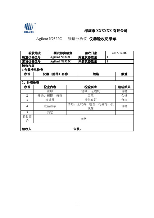
检查内容
检验要求
检验结果
1
丝印
清晰、无瑕疵
合格
2
开关、按键、按钮
灵活
合格
3
接插件
接触良好
合格
4
液晶显示
清晰,无缺画、色差、花屏等不良现象
合格
5
其它
验收结论
合格
验收人:审核:
附件:验收记录
一、包装清单序号Biblioteka 名称规格数量
1
主机
规格:N9322C
1
机身编号:CN0743A104
1
2
交流电源线
8121-1606(电源线)
合格
Amplitude整幅
按下Amplitude,进入子菜单,能进行各参数设置
能进行各参数设置
合格
其余按钮
按下按钮,进入相关子菜单,在子菜单栏里能进行各项设置
能够设置参数
合格
4、频率测试
序号
信号发生器频率
频谱仪频率(MHz)
频谱仪功率(dBm)
测试结果
频率(MHz)
衰减倍数
1
10.008
20
10.00
合格
三、功能测试
对频谱分析仪主要功能进行测试。
1、开机测试
测试名称
测试要求
测试结果
开关机
连续开关机10次,不应出现不开机,开机异常,自动开机,自动关机等现象
合格
2、可靠性测试
测试名称
测试要求
测试结果
连续运行24小时测试
连续运行24小时无重启、无死机等异常现象出现
合格
3、按键功能测试
按键名
测试方法
测试要求
频谱分析仪技术指标的定义

频谱分析仪技术指标的定义(1)频率稳定度:频率或幅度在一段时间内保持不变的能力,在频谱仪中,稳定度是指本振固定在一个特殊频率上的能力。
(2)分辨率带宽(RBW):频谱仪区分两个相邻输入正弦信号的能力。
(-3dB点对应的带宽)。
(3)选择性:测试正弦信号时的-60dB/-3dB 带宽比。
与进行FFT 运算时所采用的数字滤波器的形状有关。
(4)带宽精度:实际的-3dB带宽值对应标称值的误差范围。
(5)视频带宽(VBW):在频谱分析仪中用图像(滤波)带宽表示图像显示电路的可调低通滤波器的3分贝点截止频率。
当它等于或小于分辨率带宽时,图像显示电路不能完全响应包络检波器的快速变化信号。
结果看到的测量曲线是平滑的,平滑程度由图像滤波器带宽与分辨率带宽的比决定。
(6)相位噪声:频率的极短期变化由相位噪声指标给出。
相位噪声以在对源频率的某一频率偏移上归一化到1Hz带宽的dBc(相对于“载波”或源频率的dB数)表示,典型的指标表述为在10kHz偏移处 < -90dBc(1Hz BW)。
(7)显示平均噪声电平:在无信号输入下,本机噪声的平均值。
测试结果与分辨率带宽有关,分辨率带宽缩小10倍则相位噪声电平减少10dB。
(8)二次谐波:在信号的频谱里,二倍于基波信号频率的信号分量。
用二次谐波信号与基波信号的幅度差值来表示。
(9)三阶互调:是指当两个信号在一个线性系统中,由于非线性因素存在使一个信号的二次谐波与另一个信号的基波产生差拍(混频)后所产生的寄生信号。
(10)剩余响应:是无信号输入情况下,在频谱仪显示中出现的离散响应。
是由于混频过程中频谱仪内部信号的不完全屏蔽产生的。
(11)幅度精确度:幅度测量的不确定度,有相对和绝对精度之分。
(12)显示动态范围:大小信号都能被同时显示在屏幕上的最大动态范围,对于每格10dB对数显示的频谱分析仪而言,实际动态范围会高于显示动态范围。
(13)失真:信号波形在传输系统中不期望的变化。
频谱分析仪的使用方法

频谱分析仪的使用方法频谱分析仪是一种用于测量信号频谱的仪器,它可以帮助我们分析信号的频率成分和功率分布,对于电子、通信、无线电等领域的工程师和技术人员来说,频谱分析仪是一种非常重要的工具。
在本文中,我们将介绍频谱分析仪的基本使用方法,希望能够帮助读者更好地掌握这一工具的操作技巧。
首先,使用频谱分析仪之前,我们需要确保设备的连接是正确的。
通常情况下,频谱分析仪会有一个输入端和一个输出端,我们需要将待测信号连接到输入端,并将输出端连接到显示设备或者记录设备上。
在连接好设备之后,我们需要打开频谱分析仪,并进行一些基本的设置。
接下来,我们需要设置频谱分析仪的中心频率和带宽。
中心频率是我们希望观测的信号频率,而带宽则是我们希望观测的频率范围。
通过设置这两个参数,我们可以确保频谱分析仪能够准确地捕捉到我们感兴趣的信号。
在设置好中心频率和带宽之后,我们需要调整频谱分析仪的分辨率带宽。
分辨率带宽是指频谱分析仪在测量信号时的频率分辨能力,通常情况下,分辨率带宽越小,频谱分析仪的测量精度就越高。
因此,我们需要根据实际情况来调整分辨率带宽,以确保我们能够获得准确的测量结果。
在进行测量之前,我们还需要注意一些其他的设置,比如参考电平、RBW(分辨率带宽)、VBW(视频带宽)等参数的设置。
这些参数会影响到频谱分析仪的测量结果,因此我们需要根据实际情况来进行调整。
当所有的设置都完成之后,我们就可以开始进行信号的测量和分析了。
在测量过程中,我们需要注意观察频谱分析仪的显示屏,以确保我们能够及时地发现信号的变化。
同时,我们还可以通过调整频谱分析仪的参数,比如RBW和VBW,来获得更加详细和准确的测量结果。
除了基本的测量功能之外,一些先进的频谱分析仪还具有其他的功能,比如谐波分析、调制解调功能、无线电频谱监测等。
这些功能可以帮助我们更加全面地了解信号的特性,对于一些特定的应用场景来说,可能会有非常重要的意义。
总的来说,频谱分析仪是一种非常重要的测量工具,它可以帮助我们分析信号的频率成分和功率分布,对于电子、通信、无线电等领域的工程师和技术人员来说,掌握频谱分析仪的使用方法是非常重要的。
Keysight N9320B RF Spectrum Analyzer 配置指南说明书
Keysight TechnologiesN9320B RF Spectrum AnalyzerConfiguration GuideThe Keysight Technologies, Inc. N9320B is a general purpose spectrum analyzer from 9 kHz to 3 GHz. Its standard features include:–Frequency power measurements–One-button power suite, auto tune, and frequency counter –AM/FM tune and listen–12 markers, 4 traces, and 2 customer-definable limit lines –U2000 Series USB power sensor support–USB and LAN connectivity This step-by-step process will help you to configure yourN9320B RF spectrum analyzer by tailoring its options to meet your requirements.For detailed specifications, refer to the N9320B spectrum analyzer data sheet (5990-8119EN). For a product overview, refer to the N9320B spectrum analyzer brochure (5990-8118EN).Ordering informationmodulation rate, AM depth, frequency deviation, SINAD1, and carrierfrequency offsetASK and FSK demodulation metrics N9320B-DMA Provides modulation metrics of an ASK or FSK signal: Carrier power,ASK error, depth, and index, FSK deviation, FSK error, magnitude error,and carrier frequency offset1.Signal-to-noise and distortion ratio200 Hz, 9 kHz, 120 kHz, and 1 MHz pre-compliance measurementsGPIB interface N9320B-G01IEEE-488 bus connector, used in test automation systems Customized save-last utility N9320B-C20N9320B automatically saves its settings and status once any changes aremade. After the power cycle, the N9320B recovers the prior setups beforepowering offInstrument power-on utility at AC power cycle N9320B-C30N9320B powers on directly at AC power cycle without the user pushingthe power-on button on the unit’s front panel. A solution designed for testautomation systemsPrepared for RF teaching labs or training agenciesHard transit case (D x W x H)N9320B-1TC–645 x 444 x 268 mm, 13 kg nominal–25.4 x 17.5 x 10.6 in, 29 lb nominalRack mount kit N9320B-1CM Includes a rackmount flange and front handle kit. Fits standard 19-inch rackand occupies three units of rack spaceHandle and bumper N9320B-1HB Available for ordering only at time of initial instrument purchaseNeed more RF and microwave accessories? Visit /find/accessoriesprovides measurement resultsSelect Keysight Calibration Plan3-year calibration assurance plan (return to Keysight)R-50C-011-3Priority calibration service covering all calibration costs for3 years; 15% cheaper than buying stand-alone calibrations5-year calibration assurance plan (return to Keysight)R-50C-011-5Priority calibration service covering all calibration costs for5 years; 20% cheaper than buying stand-alone calibrationsOther calibration options may available, for more information on calibration, go to: /find/calibration. For more information on training and application support services, go to: /find/training.Instrument UpgradesMost of the Keysight N9320B RF spectrum analyzer options are available for post-sales retrofit.For license-key upgrades that do not require additional hardware:1. Place an order for the upgrade with Keysight and requestto receive the software entitlement certificate through email2. Install the license key in the N9320B. Upgrade firmware tothe latest revision if required 3. Restart the N9320B4. Begin using the new capabilityDescriptionUpgrade number Additional informationAdd preamplifier, 3.0 GHz N9320BK-PA3Add AM/FM demodulation metrics N9320BK-AMA Add ASK/FSK demodulation metrics N9320BK-DMA Add tracking generator, 100 kHz to 3.0 GHz N9320BK-TG3The tracking generator is additional hardware that is installed inside the N9320B. Upgrade is performed at Keysight’s local service center Add GPIB interface N9320BK-G01Requires additional hardware be installed inside the N9320BAdd EMC filter (-6 dB down)N9320BK-EMF Add hard transit case N9320BK-1TC Add rack mount kitN9320BK-1CM Add customized save-last utilityN9320BK-C20Add instrument power-on utility at AC power cycle N9320BK-C30Upgrade performed at Keysight’s local service center Revision to currentN9320BK-R2CEnables the latest feature set for the instrumentA comprehensive summary about the N9320B upgrades is also available at: /find/n9320b_upgrade .Other InformationKeysight product registrationRegister your instruments for service notifications, firmware update alerts, application notes and more. You have the Keysight edge. Register today and keep it sharp: /find/register .Keysight education cornerYour one-stop education resource for college and university engineering educators, researchers and students: /find/edu .Related LiteraturePublication number Publication title5990-8116ENKeysight N9310A RF Signal Generator , Data SheetmyKeysight/find/mykeysightA personalized view into the information most relevant to you.Keysight Infoline/find/InfolineKeysight’s insight to best in class information management. Free access toyour Keysight equipment company reports and e-library.Keysight Services/find/service sOur deep offering in design, test, and measurement services deploys anindustry-leading array of people, processes, and tools. The result? We helpyou implement new technologies and engineer improved processes thatlower costs.Three-Year Warranty/find/ThreeYearWarrantyKeysight’s committed to superior product quality and lower total costof ownership. Keysight is the only test and measurement company withthree-year warranty standard on all instruments, worldwide. And, we providea one-year warranty on many accessories, calibration devices, systems andcustom products.Keysight Assurance Plans/find/AssurancePlansUp to ten years of protection and no budgetary surprises to ensure yourinstruments are operating to specification, so you can rely on accuratemeasurements.Keysight Channel Partners/find/channelpartnersGet the best of both worlds: Keysight’s measurement expertise and productbreadth, combined with channel partner convenience./find/n9310bFor more information on KeysightTechnologies’ products, applications orservices, please contact your local Keysightoffice. The complete list is available at:/find/contactusAmericasCanada(877) 894 4414Brazil55 11 3351 7010Mexico001 800 254 2440United States(800) 829 4444Asia PacificAustralia 1 800 629 485China800 810 0189Hong Kong800 938 693India 1 800 11 2626Japan0120 (421) 345Korea080 769 0800Malaysia 1 800 888 848Singapore180****8100Taiwan0800 047 866Other AP Countries(65) 6375 8100Europe & Middle EastAustria0800 001122Belgium0800 58580Finland0800 523252France0805 980333Germany***********Ireland1800 832700Israel 1 809 343051Italy800 599100Luxembourg+32 800 58580Netherlands0800 0233200Russia8800 5009286Spain800 000154Sweden0200 882255Switzerland0800 805353Opt. 1 (DE)Opt. 2 (FR)Opt. 3 (IT)United Kingdom0800 0260637For other unlisted countries:/find/contactus(BP-06-08-16)/go/qualityKeysight Technologies, Inc.DEKRA Certified ISO 9001:2015Quality Management SystemThis information is subject to change without notice.© Keysight Technologies, 2013 - 2016Published in USA, October 13, 20165990-8120ENEvolvingOur unique combination of hardware, software, support, and people can helpyou reach your next breakthrough. We are unlocking the future of technology.From Hewlett-Packard to Agilent to Keysight。
使用Agilent N9322C做标量传输测量
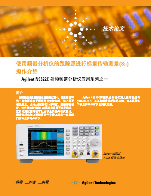
Solutions for简介在射频设计或者射频故障诊断过程中,通常需要评估一些有源或者无源器件的关键指标,但不需要相位信息,比如: 滤波器的3 dB 带宽、插损和抑制度,放大器的增益和1 dB 压缩点等是否满足需求,这样的测试通常就可以由标量网络分析仪完成。
频谱分析仪加上跟踪源选件实质上就是一台单端口的标量网络分析仪。
使用频谱分析仪的跟踪源进行标量传输测量(S 21)操作介绍— Agilent N9322C 射频频谱分析仪应用系列之一技术论文Agilent N9322C 射频频谱分析仪加上跟踪源选件 (N9322C-TG7), 不但有频谱分析仪的功能,而且还具备了标量网络分析仪的测试功能。
Agilent N9322C 7-GHz 频谱分析仪标量网络分析仪提供了激励-响应的测试能力,激励-响应测试主要用于测试被测件的传输参数S21和反射参数S11。
通过传输测试,可以获得被测件的增益、频响、插损和平坦度指标情况; 通过反射测试,可以得到被测件的回波损耗指标。
Agilent N9322C跟踪源选件的相应指标如下:频率o 范围: 5 MHz 至 7 GHzo 分辨率: 1 Hzo 分辨率带宽: 3 kHz 至 3 MHz输出功率o 范围: –20 至 0 dBmo 分辨率: 1 dB测量动态范围o Max. Output power 至 D ANL with 3 kHz RBWAgilent N9322C传输测量操作步骤本文只阐述传输测试的操作步骤,关于反射测试,请参考N9322C反射测量文档。
被测件和N9322C的测试连接如图1所示,但为了保证传输测试结果精确,通常需要进行下面简述的三步操作:1. 根据被测件的实际需求来设置N9322C的频率、分辨率带宽、扫描时间、输入衰减、跟踪源的输出信号幅度等。
2. 移去被测件,使用标准连接器来替代被测件,使N9322C的跟踪源输出端口与其射频输入端口直接连接,然后打开归一化功能,确定一个0 dB的参考线。
频谱分析仪使用方法_百度文库.

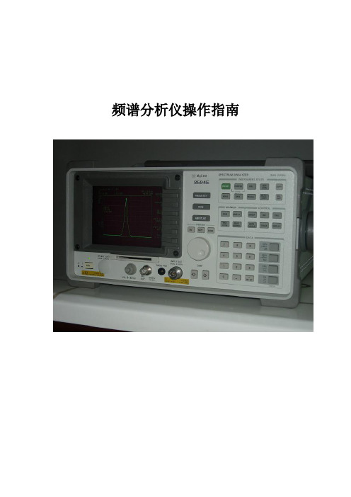
目录频谱分析仪操作指南 ................................................................................................... 1第一节仪表板描述 .. (1)一、前面板 (1)二、后面板 (略 . (6)第二节基本操作 (6)一、菜单操作和数据输入 (6)二、显示频谱和操作标记 (8)三、测试窗口和显示线 (12)四、利用横轴测试频率 (16)五、自动调整 (19)七、 UNCAL 信息 ............................................................................................. 22 第三节菜单功能描述 (24)频谱分析仪操作指南 JV 手机维修处频谱分析仪操作指南第一节仪表板描述一、前面板这部分包括前面控制板详细的视图、按键解释和显示在那些图片上的连接器, 这可从频谱仪的前部面板看到,共分为九个部分,如下所述:1、显示部分21 23、软盘驱动部分4、 MEASUREMENT 部分1 24 □5STOP635、 DATA 部分6、 MARKER 部分447、 CONTROL 部分1 68、 SYSTEM 部分□ REMOTE1 PRESET3 49、混杂的部分10、屏幕注释312图 1屏幕注释二、后面板 (略第二节基本操作一、菜单操作和数据输入用面板按键和选项去操作频谱分析仪。
使用面板键时, 一个常见的菜单会显示在屏幕的右边。
但是,有一些键没有相关的软菜单,如 AUTO TUNE和 COPY 键。
每菜单选项与功能键一一对应。
选择一个菜单,需要按相应的功能键。
在一些情形中, 按功能键显示附加选项。
下面的例子指出了仪表板和软按键功能的多少。
1、选择菜单按 LEVEL 键显示用于安装测试的菜单。
参考线值显示在活动区域中,电平菜单显示在屏幕的右边,显示如下Ref LevelATT AUTO/MNLdB/divLinearUnitsRef Offset ON/OFF2、输入数据当一个值显示在激活区时,你可利用数字键、步进键或数据旋钮改变它。
频谱分析仪的使用方法
频谱分析仪的使用方法频谱分析仪的使用方法(第一页)13MHz信号。
一般情况下,可以用示波器判断13MHz电路信号的存在与否,以及信号的幅度是否正常,然而,却无法利用示波器确定13MHz电路信号的频率是否正常,用频率计可以确定13MHz电路信号的有无,以及信号的频率是否准确,但却无法用频率计判断信号的幅度是否正常。
然而,使用频谱分析仪可迎刃而解,因为频谱分析仪既可检查信号的有无,又可判断信号的频率是否准确,还可以判断信号的幅度是否正常。
同时它还可以判断信号,特别是VCO信号是否纯净。
可见频谱分析仪在手机维修过程中是十分重要的。
另外,数字手机的接收机、发射机电路在待机状态下是间隙工作的,所以在待机状态下,频率计很难测到射频电路中的信号,对于这一点,应用频谱分析仪不难做到。
一、使用前须知在使用频谱分析仪之前,有必要了解一下分贝(dB)和分贝毫瓦(dBm)的基本概念,下面作一简要介绍。
1.分贝(dB)分贝是增益的一种电量单位,常用来表示放大器的放大能力、衰减量等,表示的是一个相对量,分贝对功率、电压、电流的定义如下:分贝数:101g(dB)分贝数=201g(dB)分贝数=201g(dB)例如:A功率比B功率大一倍,那么,101gA/B=10182’3dB,也就是说,A功率比B功率大3dB,2.分贝毫瓦(dBm)分贝毫瓦(dBm)是一个表示功率绝对值的单位,计算公式为:分贝毫瓦=101g(dBm)例如,如果发射功率为lmw,则按dBm进行折算后应为:101glmw/1mw=0dBm。
如果发射功率为40mw,则10g40w/1mw--46dBm。
二、频谱分析仪介绍生产频谱分析仪的厂家不多。
我们通常所知的频谱分析仪有惠普(现在惠普的测试设备分离出来,为安捷伦)、马可尼、惠美以及国产的安泰信。
相比之下,惠普的频谱分析仪性能最好,但其价格也相当可观,早期惠美的5010频谱分析仪比较便宜,国产的安泰5010频谱分析仪的功能与惠美的5010差不多,其价格却便宜得多。
频谱分析仪使用手册
频谱仪使用手册ES A系列频谱分析仪使用手册通信网络管理中心通信枢纽室频谱仪使用手册目录第一章安装和设置 (3)1、初始检查 (3)2、电源要求 (4)3、首次开启分析仪 (6)4、运行内部对准 (8)5、打印机设置和操作 (9)6、防止静电释放 (13)第二章前面板和后面板特性 (14)1、前面板概览 (14)2、后面板特性 (20)3、键概述 (24)4、前面板和后面板符号 (25)第三章进行基本测量 (27)1、使用前面板 (27)2、预设频谱分析仪 (27)3、查看信号 (28)第四章查看类别和保存文件 (35)1、文件菜单功能 (35)2、创建目录 (38)3、格式化软盘 (39)4、保存文件 (40)5、装入文件 (43)6、重命名文件 (45)7、复制文件 (46)8、删除文件 (48)9、使用Alpha Editor (49)第5章应用范例 (49)1、常用测试步骤: (49)2、其他设置及功能: (50)第一章安装和设置本手册提供E S A—E和ES A—L系列仪器的文档资料,具体如下:E S A-E系列 E4401B(9k Hz—1.5G Hz)E4402B(9k Hz-3。
0G Hz)E4404B(9k Hz- 6.7G Hz)E4405B(9k H z-13。
2GH z)E4407B(9k H z—26.5GH z)ES A—L系列E4411B(9k Hz— 1.5G Hz)E4403B(9k H z—3。
0G H z)目前在用类型 E4408B(9k H z—26。
5GHz)制造商产品编号E4401-904861、初始检查检查包装箱和衬垫材料有无被压的迹象。
保留装运材料以备将来使用,因为您可能需要将分析仪运到其他地方,或运到安捷伦科技公司进行维修。
核实包装箱内的物品是否完整。
下表列出了随分析仪一同装运的物品。
转接头,BNC(阳)转F (阴),75注意:如果您购买了一个或多个测量个性化选件,则所订购的这些选件的相关指南也包括在其中.标准文档集中不包括维修文档。
频谱仪操作使用指南

频谱仪操作使用指南频谱仪是一种用来显示信号频谱分布的仪器,用于分析信号的频率、功率和幅度等参数。
频谱仪广泛应用于通信、广播、电子、雷达等领域,在调试和故障排除中起着至关重要的作用。
下面是频谱仪的操作使用指南。
一、频谱仪的基本原理和组成部分1.频谱仪的原理:频谱仪通过将输入信号分解成一系列不同频率的正弦波,然后测量每个正弦波的幅度和相位,最后将结果显示在屏幕上,形成频谱图。
2.频谱仪的组成部分:-输入部分:用于接收待测信号的输入接口,常见的有天线接口、信号源接口等。
-信号处理部分:将接收到的信号进行放大、滤波和混频等处理,以便进行频谱分析。
-显示部分:将处理后的信号以图形的方式显示在屏幕上,通常有频谱图、扫描图和水平轴等。
-控制部分:用于设置和调整频谱仪的参数,如中心频率、带宽、参考电平等。
二、频谱仪的操作流程1.连接信号源:将待测信号源与频谱仪进行连接,确保输入信号的准确性和稳定性。
2.设置基本参数:首先设置中心频率,即希望观察的信号的中心频率。
然后设置带宽,即希望观察的信号的频率范围。
最后设置参考电平,用于设定垂直轴的单位和刻度。
3.调整时间/功率纵轴:根据需要,选择时间或功率纵轴显示模式。
在时间模式下,频谱仪以时间为基准显示信号的幅度和相位信息;在功率模式下,频谱仪通过电平来显示信号的幅度。
4.检查实时扫描图:启动实时扫描图功能,观察信号在不同频率下的强度变化情况。
可以通过调整带宽和参考电平来获取所需的图像效果。
5.分析频谱图:通过频谱图可以观察信号的频率分布情况。
可以对频谱图进行放大、缩小、移动等操作,以便更详细地分析和观察信号。
6.添加标记和测量:根据需要,可以添加标记来测量信号的频率、功率、幅度等参数。
频谱仪通常提供了多种测量方式,如峰值、平均、最大、最小等。
7.导出和保存数据:频谱仪通常具有数据导出和保存的功能,可以将分析结果导出到计算机或其他设备中,以便后续处理和分析。
三、频谱仪的使用注意事项1.频谱仪的输入信号要求稳定且幅度适当,过大或过小的输入信号都会影响测量结果的准确性和可靠性。
(完整版)频谱仪使用说明
频谱分析仪操作指南目录频谱分析仪操作指南 (2)第一节仪表板描述 (2)一、前面板 (2)二、后面板(略) (7)第二节基本操作 (7)一、菜单操作和数据输入 (7)二、显示频谱和操作标记 (9)三、测试窗口和显示线 (13)四、利用横轴测试频率 (17)五、自动调整 (20)七、UNCAL信息 (23)第三节菜单功能描述 (25)频谱分析仪操作指南第一节仪表板描述一、前面板这部分包括前面控制板详细的视图、按键解释和显示在那些图片上的连接器,这可从频谱仪的前部面板看到,共分为九个部分,如下所述:1、显示部分23、软盘驱动部分4、MEASUREMENT部分124□5STOP65、DATA 部分6、MARKER 部分47、CONTROL 部分168、SYSTEM部分□REMOTE1PRESET□SHIFT349、混杂的部分10、屏幕注释312图1屏幕注释二、后面板(略)第二节基本操作一、菜单操作和数据输入用面板按键和选项去操作频谱分析仪。
使用面板键时,一个常见的菜单会显示在屏幕的右边。
但是,有一些键没有相关的软菜单,如AUTO TUNE和COPY键。
每菜单选项与功能键一一对应。
选择一个菜单,需要按相应的功能键。
在一些情形中,按功能键显示附加选项。
下面的例子指出了仪表板和软按键功能的多少。
1、选择菜单按LEVEL键显示用于安装测试的菜单。
参考线值显示在活动区域中,电平菜单显示在屏幕的右边,显示如下Ref LevelATT AUTO/MNLdB/divLinearUnitsRef Offset ON/OFF2、输入数据当一个值显示在激活区时,你可利用数字键、步进键或数据旋钮改变它。
●利用数字键输入数据可利用下面的键输入数据:数字键(0到9),小数点键,和退格(BK SP)或减号(-)键。
如果你使用数字键时出错,你可用退格(BK SP)键删除最近输入的数字。
如果你没有输入任何数据,按BK SP键输入一个减号(-)。
Keysight CSA Spectrum Analyzer N1996A 技术参考手册说明书
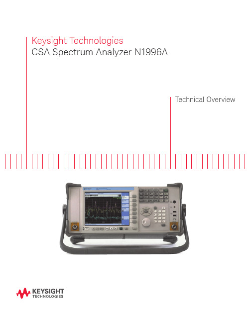
Keysight TechnologiesCSA Spectrum Analyzer N1996ATechnical OverviewExceptional performance...anytime, anywhereFrequency coverage–Frequency range: 100 kHz to 3 or 6 GHz –Signal source: 10 MHz to 3 or 6 GHz –Preamplifier to 3 or 6 GHzPerformance–DANL: -156 dBm/Hz, normalized to 1 Hz –Best-in-class dynamic range with +18 dBm TOI –Overall amplitude accuracy: ±0.5 dBCompact Design–Weight: 7.5 kg with built-in signal source, preamplifier, and VSWR bridge –Battery life: 2 hours (typical)Features–Brightest, highest resolution display in its class (21 cm XGA, 1024 x 768) –1 dB electronic step input attenuator–10 Hz to 5 MHz RBW standard, 10% adjustable to 200 kHz, 1 Hz to 50 MHz VBW –USB and LAN standardTraditional Keysightquality and reliability with the performance you need, the convenience you want, and the price you can afford...The Keysight CSA Spectrum AnalyzerLight weight and portable at 8.5 kg with batteriesBuilt-in preamplifier increases sensitivityVSWR bridge is built-in, reducing the complexity of stimulus/response measurementsSignal source enables system, cable, and component measurements Shallow depth of 25 cm(with bumpers) conserves bench spaceBuilt-in helpUSB 1.1 ports simplify data transfer and connectivity1 dB step attenuator (best in class)A general purpose spectrum analyzer is the engineer’smost flexible test tool. The Keysight Technologies, Inc. CSA spectrum analyzer extends that flexibility with its performance, ease-of-use, and unprecedented reliability.Performance and quality you expect at a price you can affordThe Keysight CSA spectrum analyzer brings a level of performance not seenpreviously in a compact spectrum analyzer. The highest dynamic range in its price class is achieved with unmatched distortion performance, substantial noise performance, and standard 10 Hz resolution bandwidth. The instrument also offers overall amplitude accuracy of ±0.5 dB. Now you get all of this capability and more, with excellent reliability and low service and support costs.Ease-of-use means greater efficiencyThe user interface is designed to give expert users access to all of the power of the Keysight CSA. Logically grouped hard keys, soft keys, and menus allow intuitive control of parameters like input attenuation, bandwidth, and detector type. Features such as auto-tune, auto-scale, auto-range, 1 dB step attenuator, built-in preamp, and onboard help make the Keysight CSA easy to use even for non-experts.AC adapter USB 1.1100 base-T LAN Frequencyreference in/outExternaltrigger Security cable slotTraditional Keysightquality and reliability with the performance you need, the convenience you want, and the price you can afford...Easy to upgradeUnique among our products, each Keysight CSA spectrum analyzer comes with options installed, ready to be activated. This allows for easy upgrades, enabling users to reconfigure the instrument as needs change. Signal source and preamplifier upgrades may require service center calibration.Connectivity is simpleTransport data to a PC easily via USB memory device. Download firmware upgrades from the Web into the instrument. Remotely control your instruments using SCPI commands over a 100 base-T LAN.Accurate, Rugged, Dependable, and FlexibleThe Keysight CSA is optimized formanufacturing with its combination ofhigh performance, modern connectivity,and the industry’s best reliability.The instrument was designed for fast sweep speeds innarrow resolution bandwidths and fast in-channelmeasurements, as well as the highest achievabledynamic range in its price class. Remote control via100 Base T LAN and SCPI reduce the complexity and timeto develop automation software, enhance compatibilitywith existing systems, and reduce training time formanufacturing staff. All of these attributes are designedto reduce cost-of-test, while the excellent reliability assuresthe lowest overall cost of ownership.Now you can afford the excellenceof a Keysight spectrum analyzer ateach engineer’s bench!You get true Keysight performance with TOI of +18 dBm,10 Hz minimum RBW (1 Hz minimum VBW) with 10%adjustability, and 1 dB step attenuator. The large, bright,21 cm, 1024 x 768 pixel, XGA display (best-in-class),convenient form factor, and straightforward portabilityof data with a USB memory device make the KeysightCSA spectrum analyzer easy to use. Features like auto-tuneand auto-scale ensure that newer users can quickly makeuse of this extensive performance and capability.The Keysight CSA’s field-ready featuresmake it an ideal choice for installationand maintenance of today’s complexcommunication systems.Weighing just 7.5 k (16.5 lbs) with rugged bumpers,and a comfortable, adjustable bail handle, the Keysight CSAspectrum analyzer is able to deliver powerful measurementcapability where and when you need it. This analyzer hasmore than two hours of battery life and a bright, high-resolution display, perfect for use in the field. Thisinstrument combines the functionality of a general-purposespectrum analyzer, network analyzer, and power meter intoa simple, easy-to-use package. The built-in VSWR bridge,optional internal signal source, and stimulus/ responsemeasurement suite confirm the Keysight CSA spectrumanalyzer as the best installation and maintenance solutionin its price class.The Keysight CSA brings the power ofspectrum analysis to the teaching lab,enabling professors to easily communicatesignal theory to their students.Easy transformation between time and frequency domainssimplifies the understanding of digital modulation formats.Built-in help and auto-setup features bring full spectrumanalysis capability into the hands of aspiring experts. Withthe shallow form factor conserving valuable lab benchspace, exceptional performance, and affordable price, theKeysight CSA spectrum analyzer is a sensible addition toundergraduate and technical teaching lab stations.background sweep, optimizing input attenuation and preamplifier settings, ensuring that off-screen signals are not compressing the RF stage, assuring accurate measurement results.Communication channel measurementsThe Keysight CSA spectrum analyzer includes a number ofcommunication system channel measurements, allowing users to accurately assess the performance of common wireless telephony and other channel-based communication systems and components. Using preset format-based or customparameters, the operator can easily determine distortion levels and channel power using the adjacent channel power function. Similarly, the occupied bandwidth function quickly determines power and bandwidth of signals with complex modulation.Measurements and FeaturesReturn loss, cable fault, and insertionloss capabilitiesThe Keysight CSA’s built-in signal source andVSWR bridge enable a powerful range of scalar measurements not commonly found in general purpose spectrum analyzers. With the stimulus/response measurement suite, the Keysight CSA spectrum analyzer can characterize active and passive single and dual-port devices such as cables, filters, amplifiers, multiplexers, antennas, and switches. Measurements included are 1 and 2 port insertion loss, return loss, and distance-to-fault. The combination of robust capabilities and spectrum analysis tools can greatly simplify and accelerate installation and maintenance of complex components and systems.Use the spectrogram to analyze the stabilityof a signal over time, or to detect and identify signals interfering with the system of interest. The spectrogram view is essentially a time capture of spectral activity that can be optimized to focus on an area of interest, detailing differences in the frequency and amplitude of spectral components as a function of time.A common use for spectrograms is in the identification and eradication of unwanted interference in communications systems. Spectro-grams can also monitor the stability of a circuit or system over time, temperature, vibration, etc.The Keysight CSA’s optional modulationmeasurement suite provides functional and parametric analysis of AM and FM. Whether you’re making modulation depth or frequencydeviation measurements for AM or FM devices, the Keysight CSA spectrum analyzer gives you the full range of metrics you need. The detailed measurement information – including deviation, modulation rate, distortion, SINAD, and carrier power – ensures a full understanding of the modulation characteristics. Both time domain and frequency domain views of the data allow you to analyze the signal quickly from different perspectives. The tune-and-listen option capability lets you hear the signal and classify it based on its audio qualities.Analyze pulsed signalsThe CSA clearly and easily displays pulsed signals in the frequency domain. You can measure the amplitude difference between a CW signal and a pulsed signal. The example to the right shows the Sinx/x of a pulsed signal along with the associated CW signal.SpecificationsFrequency Range100 kHz to 3 GHz (Option 503)100 kHz to 6 GHz (Option 506)Frequency readout accuracy± {frequency indication x frequency reference accuracy +1% x span + 10% x RBW + 0.5 x [span/(sweep points -1)] + 1Hz}Internal reference accuracy ≤ ± 5 ppm/year (within 2 years of adjustment)Aging rate≤ ± 2 ppm/year Temperature stability≤ ± 1 ppmResolution bandwidth (RBW)10 Hz to 200 kHz in 10% steps, 250 kHz, 300 kHz, 510 kHz, 1 MHz, 3 MHz, 5 MHz Selectivity (60 dB/3 dB bandwidth ratio)Digital, approximately Gaussian shape Span > 0; RBW ≤ 200 kHz Span > 0; RBW ≥ 250 kHz Zero span; RBW ≤ 10 kHz Zero span; RBW ≤ 200 kHz Zero span < 8.4:1 (nominal)< 4.5:1 (nominal)< 6.5:1 (nominal)< 3:1 (nominal)3 kHz to 5 MHz in 1, 3, 5 sequence, 250 kHz and 1.25 MHz Accuracy(RBW ≤ 200 kHz)(RBW = 250 kHz, 300 kHz, 1 MHz, 3 MHz)< 2% zero span; < 7% span > 0 (nominal)< 4% zero span; < 4% span > 0 (nominal)Video bandwidth (VBW)1 Hz to 8 MHz and 50 MHz (wide open) 1 Hz to 10 Hz in 1 Hz steps10 Hz to 3 MHz in 10% steps 4, 5, 6, 8, 30 MHz Displayed average noise level (typical)Preamp on 10 Hz RBW Preamp off 10 Hz RBWPreamp on norm to 1 Hz 500 MHz 1 GHz 2 GHz 3 GHz 4 GHz 5 GHz 6 GHz -148 dBm-146 dBm-142 dBm-144 dBm-142 dBm-139 dBm-136 dBm-130 dBm -128 dBm -124 dBm -130 dBm -128 dBm -125 dBm -122 dBm -158 dBm/Hz -156 dBm/Hz -152 dBm/Hz -154 dBm/Hz -152 dBm/Hz -149 dBm/Hz -146 dBm/HzPhase noise-85 dBc at 10 kHz offset (500 MHz to 2.5 GHz, typical)-124 dBc at 1 MHz offset (10 MHz to 2.2 GHz, nominal)-82 dBc at 10 kHz offset (2.5 to 6 GHz, typical)Sweep and trace update timesSweep time setting range (zero span) 1 µs to 10 s*Remote sweep and trace transfer Span = 0Span ≤ 100 MHz Span = 3 GHz 120 ms minimum 300 ms 1 secTrace pointsSettable 2 to 1001, 401 defaultAmplitude accuracy (20 to 30 °C)Overall amp accuracy (95% confidence)(20 to 30 °C, peak detector, preamplifier off, input signal 0 dBm to -50 dBm)Absolute amp accuracy at 50 MHz refFrequency response (when RBW ≤ 200 kHz)Scale fidelity RBW switchingAttenuator switching±0.5 dB 10 MHz to 1 GHz ±0.6 dB 1 GHz to 3 GHz ±0.8 dB 3 GHz to 6 GHz ±0.4 dB±0.7 dB 250 kHz to 10 MHz ±0.4 dB 10 MHz to 1 GHz ±0.6 dB 1 GHz to 2.7 GHz ±0.7 dB 2.7 GHz to 3 GHz ±1.1 dB 3 GHz to 6 GHz±0.2 dB (-10 to -80 dBm mixer level)±0.3 dB±0.2 dB (nominal)* RBW dependent, refer to technical specifications for detailsSpecifications(continued)Modulation rate range 100 kHz ≤ fc ≤ 10 MHz 10 MHz ≤ fc ≤ 3/6 GHz 20 Hz to 10 kHz 50 Hz to 200 kHzAM demodulationModulation depth0 to 100%Modulation rate accuracy Rate < 1 kHzRate ≥ 1 kHz 1 Hz nominal < 0.1% nominalAM depth accuracy± 3% of reading nominal FM demodulationPeak deviation100 kHz ≤ fc ≤ 10 MHz 10 MHz ≤ fc ≤ 3/6 GHz Max 40 kHz Max 400 kHzModulation rate accuracy Rate < 1 kHzRate < 1 kHz 1 Hz nominal < 0.1 % nominal1112Battery pack (2 batteries)Stimulus/response calibration kit recommendedto improve the accuracy of the stimulus/response measurement suite(N1996A-SRK)External battery charger (batteries not included)Transit case (hard cover)Soft carrying caseOrdering InformationN1996A-503 CSA base box 3 GHz (batteries not included)N1996A-506 CSA base box 6 GHz (batteries not included)N1996A-P03 Preamp 3 GHz N1996A-P06 Preamp 6 GHzN8995A-SR3 Stimulus/response suite (3 GHz)N8995A-SR6 Stimulus/response suite (6 GHz)N1996A-271 SpectrogramN1996A-SRK Stimulus/response cal. kit N1996A-1CM Rack-mount kitN1996A-1CP Rack-mount kit with handles N1996A-BAT Battery pack (2 batteries)N1996A-BCG External battery charger N1996A-SCC Soft carrying case N1996A-HTC Transit case (hard cover)N1996A-ABA Manual hard copy (English)N1996A-ABJ Manual hard copy (Japanese)N1996A-AB2 Manual hard copy (Simplified Chinese)N1996A-0BW Service documentation 4. T he 6 GHz preamplifier (Option P06) is for use with the 100 kHz to 6 GHz frequency range (Option 506).5. T he N1996A-HTC transit case is designed to be used with the N1996A-SCC soft carrying case.6. N 1996A-AFM AM/FM tune and listen is for both Option 503 and Option 506.7. N 8996A-1FP AM/FM Demodulation metric is for both Option 503 and Option 506.For more information on KeysightTechnologies’ products, applications or services, please contact your local Keysight office. The complete list is available at:/find/contactus Americas Canada (877) 894 4414Brazil 55 11 3351 7010Mexico001 800 254 2440United States (800) 829 4444Asia Pacific Australia 1 800 629 485China800 810 0189Hong Kong 800 938 693India 1 800 112 929Japan 0120 (421) 345Korea 080 769 0800Malaysia 1 800 888 848Singapore 180****8100Taiwan0800 047 866Other AP Countries (65) 6375 8100Europe & Middle East Austria 0800 001122Belgium 0800 58580Finland 0800 523252France 0805 980333Germany ***********Ireland 1800 832700Israel 1 809 343051Italy800 599100Luxembourg +32 800 58580Netherlands 0800 0233200Russia 8800 5009286Spain 800 000154Sweden 0200 882255Switzerland0800 805353Opt. 1 (DE)Opt. 2 (FR)Opt. 3 (IT)United Kingdom0800 0260637For other unlisted countries:/find/contactus(BP-09-23-14)This information is subject to change without notice.© Keysight Technologies, 2010, 2014Published in USA, July 31, 20145989-3678EN13 | Keysight | CSA Spectrum Analyzer N1996A – Technical OverviewmyKeysight/find/mykeysightA personalized view into the information most relevant to you.AdvancedTCA ® Extensions for Instrumentation and Test (AXIe) is an open standard that extends the AdvancedTCA for general purpose andsemiconductor test. Keysight is a founding member of the AXIe consortium. ATCA ®, AdvancedTCA ®, and the ATCA logo are registered US trademarks of the PCI Industrial Computer Manufacturers Group. LAN eXtensions for Instruments puts the power of Ethernet and the Web inside your test systems. Keysight is a founding member of the LXI consortium.PCI eXtensions for Instrumentation (PXI) modular instrumentation delivers a rugged, PC-based high-performance measurement and automation system.Three-Year Warranty/find/ThreeYearWarrantyKeysight’s commitment to superior product quality and lower total cost of ownership. The only test and measurement company with three-year warranty standard on all instruments, worldwide.Keysight Assurance Plans/find/AssurancePlansUp to five years of protection and no budgetary surprises to ensure your instruments are operating to specification so you can rely on accurate measurements./go/quality Keysight Technologies, Inc.DEKRA Certified ISO 9001:2008 Quality Management SystemKeysight Channel Partners/find/channelpartnersGet the best of both worlds: Keysight’s measurement expertise and product breadth, combined with channel partner convenience./find/n1996a。
keysight inline ict操作手册

keysight inline ict操作手册【原创版】目录1.Keysight Inline ICT 操作手册概述2.手册的主要内容3.如何使用手册4.手册的优点和特点正文【1.Keysight Inline ICT 操作手册概述】Keysight Inline ICT 操作手册是一本专业的测试和测量设备操作指南,它提供了对 Keysight Inline ICT 设备的全面操作说明。
无论是新手还是经验丰富的工程师,都可以通过这本手册来掌握如何有效地使用这些设备。
【2.手册的主要内容】这本手册主要包括以下几个部分:- 设备概述:详细介绍了 Keysight Inline ICT 设备的主要特性、应用场景和系统配置。
- 安装和连接:指导用户如何安装设备,并正确连接测试电路。
- 操作步骤:以步骤-by-step 的方式,详细说明了如何使用设备进行测试和测量。
- 故障排除:提供了一些常见问题的解决方案,以及如何进行设备维护和修理。
- 应用实例:通过实例,展示了如何使用 Keysight Inline ICT 设备进行各种测试和测量。
【3.如何使用手册】使用这本手册时,建议用户首先阅读设备概述部分,了解设备的基本特性和应用场景。
然后,根据需要,选择合适的章节进行阅读。
在实际操作时,建议按照手册中的步骤-by-step 进行,以确保操作的正确性。
【4.手册的优点和特点】这本手册的主要优点和特点包括:- 专业性:手册由专业的技术团队编写,内容准确、权威。
- 易用性:手册采用步骤-by-step 的方式,易于理解和操作。
- 实用性:手册中提供了大量的应用实例,可以帮助用户解决实际问题。
- 灵活性:手册支持在线阅读,用户可以随时随地查阅。
- 1、下载文档前请自行甄别文档内容的完整性,平台不提供额外的编辑、内容补充、找答案等附加服务。
- 2、"仅部分预览"的文档,不可在线预览部分如存在完整性等问题,可反馈申请退款(可完整预览的文档不适用该条件!)。
- 3、如文档侵犯您的权益,请联系客服反馈,我们会尽快为您处理(人工客服工作时间:9:00-18:30)。
N9322C Basic Spectrum AnalyzerData SheetEasy on your budget.Tough to beat performance, efficiency and simplicity.SpecificationDescribes the performance of parameters covered by the product warranty and apply to the full temperature range of 5 to 45 °C, unless otherwise noted.TypicalDescribes additional product performance information that is not covered by the product warranty. It is performance beyond specifications that 80 percent ofthe units exhibit with a 95 percent confidence level over the temperature range 20 to 30 °C. Typical performance does not include measurement uncertainty.NominalIndicates expected performance, or describe product performance that is useful in the application of the product, but are not covered by the product warranty.The analyzer will meet its specifications when: –It is within its calibration cycle–It has been turned on at least 30 minutes–It has been stored at an ambient temperature within the allowed operat-ing range for at least two hours before being turned on; if it had previously been stored at a temperature range inside the allowed storage range, but outside the allowed operating rangeLearn more about the productReference these frequently-used documents:–Brochure (5991-1166EN) –Introduces the product features–Configuration Guide (5991-1168EN)–Describes ordering information For the latest revision of prod-uct related documents or more information, visit the website: /find/n9322cDefinitions and Conditions600 ns to 1000 s Span = 0 Hz (minimum resolution = 600 ns,when RBW ≥ 30 kHz)Mode Continuous, Single Sweep time rule Accuracy or Speed Trigger Free run, video, external, RF burst Trigger slope Selectable positive or negative edge Trigger delay ± 12 ms to ± 12 s, nominal Span = 0 Hz1. Frequency reference uncertainty = Aging rate x period since adjustment + temperature stability.Frequency and Time SpecificationFrequency and Time specification(Continued)Accuracy ± 10%, nominal VBW = 1 Hz to 1 MHzAmplitude SpecificationsGain 25 dB, nominal (100 kHz to 7 GHz)15 dB, nominal (9 to 100 kHz)Dynamic Range SpecificationsTracking Generator (Option TG7)On-frequency−5 dBm, nominalOther Options50 Ω termination on input, 0 dB attenuation< −55 dBc, nominalInputs and Outputs10 MHz reference output Output amplitude> 0 dBmFrequency10 MHz ± (10 MHz × frequencyreference accuracy)Connector and impedance BNC-type female, 50 Ω, nominal 10 MHz reference input Input amplitude–5 to +10 dBm, nominalFrequency10 MHzConnector and impedance BNC-type female, 50 Ω, nominal External trigger input Input amplitude 5 V TTL level; −12.6 V, 150 mAmax (nominal)Connector and impedance: BNC-type female, 10 k ΩLAN TCP/IP interface 100Base-T, RJ-45 connectorUSB interface (device) B plug, version 1.1Mini USB (device) Mini-AB female, version 1.1GPIB interface IEEE-488 bus connector Optional G01 installed11GeneralFor more information on KeysightTechnologies’ products, applications or services, please contact your local Keysight office. The complete list is available at:/find/contactus Americas Canada (877) 894 4414Brazil 55 11 3351 7010Mexico001 800 254 2440United States (800) 829 4444Asia Pacific Australia 1 800 629 485China800 810 0189Hong Kong 800 938 693India 1 800 112 929Japan 0120 (421) 345Korea 080 769 0800Malaysia 1 800 888 848Singapore 1 800 375 8100Taiwan0800 047 866Other AP Countries (65) 6375 8100Europe & Middle East Austria 0800 001122Belgium 0800 58580Finland 0800 523252France 0805 980333Germany 0800 6270999Ireland 1800 832700Israel 1 809 343051Italy800 599100Luxembourg +32 800 58580Netherlands 0800 0233200Russia 8800 5009286Spain 0800 000154Sweden 0200 882255Switzerland0800 805353Opt. 1 (DE)Opt. 2 (FR)Opt. 3 (IT)United Kingdom0800 0260637For other unlisted countries:/find/contactus(BP-07-01-14)myKeysightA personalized view into the information most relevant to you.AdvancedTCA ® Extensions for Instrumentation and Test (AXIe) is an open standard that extends the AdvancedTCA for general purpose andsemiconductor test. Keysight is a founding member of the AXIe consortium. ATCA ®, AdvancedTCA ®, and the ATCA logo are registered US trademarks of the PCI Industrial Computer Manufacturers Group. LAN eXtensions for Instruments puts the power of Ethernet and the Web inside your test systems. Keysight is a founding member of the LXI PCI eXtensions for Instrumentation (PXI) modular instrumentation delivers a rugged, PC-based high-performance measurement and automation system.Three-Year Warranty/find/ThreeYearWarrantyKeysight’s commitment to superior product quality and lower total cost of ownership. The only test and measurement company with three-year warranty standard on all instruments, worldwide.Keysight Assurance Plans/find/AssurancePlansUp to five years of protection and no budgetary surprises to ensure your instruments are operating to specification so you can rely on accurate measurements./quality Keysight Technologies, Inc.DEKRA Certified ISO 9001:2008 Quality Management SystemKeysight Channel Partners/find/channelpartnersGet the best of both worlds: Keysight’s measurement expertise and product breadth, combined with channel partner convenience./find/n9322cThis information is subject to change without notice.© Keysight Technologies, 2014Published in USA, August 4, 20145991-1167EN13 | Keysight | N9322C Basic Spectrum Analyzer - Data Sheet。