【民间秘方】三个100%治愈痔疮的神奇秘方
BT100 Bass Amplifier用户指南说明书

BT100 BASS AMPLIFIER USER’S GUIDEIntroduction . . . . . . . . . . . . . . . . . . . . . . . . . . . . . . . . .3The Front Panel . . . . . . . . . . . . . . . . . . . . . . . . . . . .4,5The Rear Panel . . . . . . . . . . . . . . . . . . . . . . . . . . . . . .5Some Suggested Settings . . . . . . . . . . . . . . . . . . . . . .6System Block Diagram . . . . . . . . . . . . . . . . . . . . . . . .7Technical Specifications . . . . . . . . . . . . . . . .back cover2Congratulations!You are now the proud owner of the Crate BT100 Bass Amplifier. The BT100 features two different channels: a distortion channel, featuring Crate’s exclusive Shape control for quick and easy access to the tone you need, and a clean channel with a four-band rotary EQ. Another unique and valuable feature of this amplifier is the Octave control. This feature electronically creates a second signal that is one octave lower than the original signal. An active electronic tuner, conveniently located on top of the amplifier, allows you to get in tune and stay in tune “on the fly.” The Mute switch allows you to tune in silence without changing the channel Level controls. A built-in Limiter keeps your sound clean even at full output power levels, and front panel jacks are provided for connecting a CD player and a pair of headphones, thereby optimizing your practice time.Like all Crate products, your BT100 is designed by musicians and built using only the best components. Extensive testing at the hands (and ears) of skilled technicians and musi-cians insures you that this amplifier is the absolute best it can be.In order to get the most out of your new bass amp, we urge you to check out the infor-mation in this manual before you begin playing.And thank you for choosing Crate.Declaration Of Conformity#34, Effective 01-01-2001Manufacturer’s Name:SLM ElectronicsProduction Facility:1901 Congressional Drive, St. Louis, MO 63146, USAProduction Facility:700 Hwy 202 W, Yellville, AR 72687, USAShipping Facility:1400 Ferguson Ave., St. Louis, MO 63133, USAOffice Facility:1400 Ferguson Ave., St. Louis, MO 63133, USAProduct Type:Audio AmplifierComplies with the following Standards:Safety:EN60065, E60065, C22.2, UL6500 and/or UL813EMC:Directive 89/336/EEC, EN55103, EN55013, EN61000,and/or FCC 47CFR 15B clASupplementary information provided by:SLM Electronics - R & D Engineering1901 Congressional Drive, St Louis, MO 63146, USATel.: 314-569-0141, Fax: 314-569-0175341. INPUT:Use this 1/4” jack to connect your bass to the amplifier by means of a shielded instrument cable.2. -15dB/0dB:Use this switch to match the output signal level of your instrument to the amplifier. If your instru-ment has standard pickups, setting the switch to the 0dB position (switch in the out position) should yield the best results. If your bass has active electronics or high output pickups, set the switch to the -15dB position (switch depressed).3. MUTE:This switch, when depressed, interrupts the signal prior to the power amplifier, allowing you to tune your instrument in silence.4. GAIN:Use this control to adjust the amount of distortion for the Distortion channel. As you rotate the control clockwise the amount of distortion increases.NOTE:The BT100 employs an internal noise gate on the Distortion channel to keep residual noise to a minimum.The Clean channel’s Level control (#8) must be turned up above “0” in order for the noise gate to trigger proper-ly. The Gain control (#4) and input signal level also affect the noise gate.5. SHAPE:Use this control to adjust the tone of the Distortion channel, from a studio “V”-shaped tone to a more “live,” more present sound.6. LEVEL:Use this control to adjust the output level of the Distortion channel.7. CHANNEL SWITCH:Use this switch to select either channel. With the switch in the out position, the Clean channel is selected. When the switch is depressed, the Distortion channel is selected. The adjacent LED illumi-nates when the Distortion channel is selected. NOTE:When using a footswitch: when this switch is depressed,the footswitch switches between the Distortion channel and the Clean channel; when this button is in the out posi-tion, the Clean channel is always active, and the footswitch turns the Distortion channel on and off, allowing you a blend of both channels.8. LEVEL:Use this control to adjust the output level of the Clean channel, and as part of the Octave level control (see #13).9. LOW:Use this control to adjust the low frequency output of the Clean channel.10. LOW MID:Use this control to adjust the lower-midrange frequency output of the Clean channel.11. HIGH MID:Use this control to adjust the upper-midrange frequency output of the Clean channel.12. HIGH:Use this control to adjust the high frequency output of the Clean channel.13. OCTAVE:The BT100 features internal circuitry which creates a second signal which is one octave lower than the input signal. Use this control in conjunction with the Clean channel’s Level control (#8) to adjust the level of the octave signal.14. MASTER:Use this control to adjust the overall output level of the amplifier.15. LIMIT LED:This LED illuminates when the internal limiting circuit is active. Occasional flashing during play-ing is normal. If the Limit LED remains illuminated, reduce the output level of the amplifier until the LED flashes.16. CD INPUT:Use these RCA jacks to connect the line level (or headphones) output of a CD player, tape deck or rhythm machine to the amplifier. The signal level from these jacks is adjusted by the Master control (#14). If the signal from the source connected to these jacks is too strong, use the output level control on the source to adjust the signal to obtain the proper level for a good mix.17. HEADPHONES:Use this jack to listen to the amplifier through a pair of stereo headphones. The internal speaker is disconnected when the headphones jack is used. To avoid possible damage to your hearing, do not use headphones for extended periods of time at extremely loud listening levels.The Front Panel:518. POWER:Use this switch to turn the amplifier on and off. The adjacent LED illuminates when the amplifier is turned on.19. ELECTRONIC TUNER (top panel, not shown):This active electronic tuner is on whenever the amplifier is turned on, allowing you constant, “real-time” tuning. The tuner is fully chromatic – use the flat and sharp indica-tors until the LED between them illuminates, indicating proper tuning.The Rear Panel:20. AC LINE CORD (not shown):The grounded power cord should only be plugged into a grounded power out-let that meets all applicable electrical codes and is compatible with the voltage, power, and frequency require-ments stated on the rear panel. Do not attempt to defeat the safety ground connection.21. EXTERNAL SPEAKER:Use this jack to connect the amplifier to an external speaker cabinet. This jack is wired in series with the internal speaker, which remains active when this jack is used. A 4 ohm external speaker cabinet is recommended.22. FOOTSWITCH:Connect a two-button footswitch (such as the Crate CFS-2) here for remote control of the channel selection/“blend” (see #7) and octave on/off. (When the Channel Switch [#7] is depressed, the footswitch switches between the Clean channel and the Distortion channel; when the switch is in the out position, the Clean channel is always active, and the footswitch turns the Distortion channel on and off, allowing you a blend of both channels.)23. EFFECTS LOOP SEND:Use this jack to connect an external signal processor to the amplifier by means of a shielded signal cable. Connect the other end of this cable to the input jack of the external processor.24. EFFECTS LOOP RETURN:Use this jack to connect an external signal processor to the amplifier by means of a shielded signal cable. Connect the other end of this cable to the output jack of the external processor.25. BALANCED LINE OUT:Use this XLR jack to send a balanced line level signal to an external power amplifi-er, mixing board, or recording console.26. PRE/POST:Use this switch to determine whether the Balanced Line Out signal is Post-EQ (switch depressed)or Pre-EQ (switch in the out position).27. GROUND LIFT:This switch, when depressed, lifts the ground connection at the Balanced Line Out jack (#25).This may help reduce hum in the Balanced Line Out signal.28. VOLUME: Use this control to adjust the signal level at the Balanced Line Out jack (#25).POSTGND67BUFFEREQNOISE GATETUNERA BC D EF GSHAPEOCTAVEBALANCED EFFECTS BLENDEXTERNAL SENDPHONESPOWER SPEAKERATTENUATORRETURN SWITCHING CIRCUITRYBT100 Technical Specifications:Specifications subject to change without notice©2003 ST. LOUIS MUSIC, 1400 FERGUSON, ST. LOUIS, MO. 6313347-673-01 • 012904。
M-100 用户手册说明书

M-100 USER’S MANUALRESEARCH, INNOVATE, CREATE“Whenever I speak about my company I speak with the passion we have. Located in the Paris region of France, I have ensured that Micromega has the best ele-ments of my industrial group at their availability. In an age where music is dematerializing, we are committed to staying at the forefront of technology and growing under our ‘made in France’ banner.The M-one programme, with its incredible audio quality, technical capacity and sleek design represents a major advance in the history of our company. The result of three years of research by our team, we are proud to introduce to you what we believe is the most effective and complete integrated stereo amplifier of its kind.Micromega is synonymous with technological advances, expertise, reliability and sound clarity. All of our products reflect these demands.”Didier HAMDI, CEO MicromegaThe advantages of the M-One amplifier series :• High quality, A/B class amplification• Resonant power supply• Symmetrical design• Asahi Kasei AK4490 DAC converter• Acoustic correction in situ using Room EQ1 and EQ2 (included or as an op-tion)• Binaural processing of the headphone output (included or as an option)• Cover and remote control machined from aluminium block• Android and iOS compatible control app (October 2016)1 - OVERVIEW (4)1.1 Front and top (4)1.2 Back (5)1.3 Sides (ventilation) (6)1.4 Bottom (7)1.5 Infrared remote control (8)2 - CONNECTIONS (9)2.1 Phono input for a vinly turntable (9)2.2 RCA line input (10)2.3 Balanced XLR analogue input (11)2.4 Coaxial digital input (12)2.5 Optical digital input (13)2.6 AES-EBU input (14)2.7 USB input (Type B) (15)2.8 Bluetooth aptX connection (16)2.9 I²S input ..................................................................................................182.10 LAN connection .. (19)2.11 Speaker connections (20)2.12 Connecting headphones (21)2.13 Subwoofer output (22)2.14 Pre-out (23)2.15 Trigger sockets (24)2.16 Mains power supply (25)2.17 Fuse (26)3 - USER GUIDE (27)3.1 Starting up (27)3.2 Choosing your source (28)3.3 Ajusting the balance (29)3.4 A justing sensitivity (30)3.5 Renaming the sources (31)3.6 Updating the M-100 (32)3.7 Updating the network module .................................................... (33)4 - SPECIFICATIONS (34)1.1 Front and topThe M-100 amplifier has two displays so that it can be controlled from any position. The displays will automatically adjust to whichever position the amplifier is in (e.g. flat, attached to wall).There is a headphone socket on the front so that you can listen to your music in complete peace. A “Binaural” process (as an option) allows you to re-create the 3D sound scene through the headphones which is lost in classic stereophonic recordings.On the top of the device are 4 buttons which you can use to adjust the reactions of your amplifier (see section 3.1 for more information).Carefully check that the packaging is intact. If you feel it may have been tampered with or damaged please contact your vendor.Carefully remove your device from the packaging. Store the packaging in a secure, dry place: if you need to return your device to the vendor you will require the original packaging.1. Overview1.2 BACKLine level inputa n a l o gi n p u t s d i g i t a li n pu t s a n a l o gi n p u t s tri g g e rTurntableinput ROOM EQ mic plugBalanced inputCoaxial input AES - EBU inputOptical inputUSB inputI²S inputsLAN input USB update inputLeft binding postPre-outSub-outRight binding postFuseMains power supply Trigger1.3 Sides (ventilation)The M-100 amplifier should be positioned so that it can receive sufficient ventilation. Do not obstruct the air vents on the side of your amplifier. You should leave at least 10cm of space around the air vents.We advise against placing the M-100 inside a closed furniture or space1.4 BottomYou will find a connection guide under your M-100 amplifier which illustrates all of the input and ouput terminals available. Do not try to open the M-100It contains potentiallylife-threatening high voltageTake note that the M-100 has spiked feets. It can harm your furniture. Use the included rubber pads to avoid damage.1.5Infrared remote controlON / OFF MuteChange display sizeAjust volumeInput selector« Bluetooth Connect »- Press and release : pairing will start- Press and hold (for 10 seconds then release) : clear Bluetooth memory2.1 Phono input for a vinyl turntableThe « PHONO » input on the M-100 amplifier is compatible with MM and MC cartridges.You can select the correct cartridge for your turntable using the switch located on the back of the amplifier.• If your turntable has an MM cartridge, you should place the switch in the MM position •If your turntable has an MC cartridge, you should place the switch in the MC positionThere is a ‘GND’ grounding terminal near the Phono plugs so that you can connect the grounding terminal of your record player if necessary.Phono input2. CONNECTIONSMM MC2.2 RCA line inputThe M-100’s « LINE » input can be used to connect any device with RCA analogue output.RCA lineinput2.3 Balanced XLR analogue inputThe M-100’s « BALANCED» input can be used to connect any device with symmetrical analogue output.Balanced XLRanalogue input2.4 Coaxial digital inputThe M-100’s « COAX » input can be used to connect any device with an SPDIF coaxial output.The signal should be a PCM stereo signal up to 32bit/768kHz.Coaxial Digital inputYOUR BLU-RAY OR DVD PLAYER MUST BE CONFIGURED IN PCM ON THE AUDIO OUTPUTOTHERWISE IT COULD PRODUCE AN INTENSE NOISE IN YOUR SPEAKERS AND DAMAGE THEM2.5 Optical digital inputThe M-100’s « OPTO » input can be used to connect any device with a TOSlink digital connection.The signal should be a PCM stereo signal up to 24bit/192kHzOptical digital inputYOUR BLU-RAY OR DVD PLAYER MUST BE CONFIGURED IN PCM ON THE AUDIO OUTPUTOTHERWISE IT COULD PRODUCE AN INTENSE NOISE IN YOUR SPEAKERS AND DAMAGE THEM2.6 AES-EBU InputThe M-100’s « AES » input can be used to connect any device with an AES-EBU connection on XLR. The signal should be a PCM stereo signal up to 32bit/768kHz.AES - EBU input2.7 USB Input (Type B)The M-100’s « USB » input can be used to connect any computer with a USB port.The signal should be a PCM stereo signal up to 32bit/768kHz or DSD/DSD-DoP up to 11.2MHz.A USB driver will be required for any computer using Windows. You can download the driver from the M-One page on the Microme-ga website.For computers using OS X or macOS you will not need an additional driver.USB input2.8 Bluetooth® aptX® connectionThe M-100’s « BT » connection can be used to wirelessly connect smartphones, tablets, computers or MP3 players with Bluetooth®. The Bluetooth® link is compatible with aptX® for the best sound quality. To make this manual easier to read, the term « Smartphone » will be used in this section to mean smartphones, tablets, computers and MP3 players. To connect via Bluetooth® for the first time:• Ensure that the Bluetooth® function on your smartphone is turned on.• Use the remote control to click on the ‘BT’ button.• You should see the « M-ONE » appear on the list of Bluetooth® connections available on your smartphone. To establish a connection select the « M-ONE ».• Launch music on your smartphone.To connect via Bluetooth® with a different smartphone, tablet etc.• Ensure that the Bluetooth® function on your smartphone is turned on.• Use the remote control to click on the ‘BT’ button.• Then press release the « BTC » button on the remote control.• You should see the « M-ONE » appear on the list of Bluetooth® connections available on your smartphone. To establish a connection select the « M-ONE ».• Launch play on your smartphone.The following time you select the BT input :• If the Bluetooth® on your smartphone is turned on, the connection will work automatically once you select the ‘BT’ button on the amplifier using the remote.NB : Bluetooth® is a « point to point » connection. This means that if a tablet is already connected to the amplifier, you will not be able to connect your smartphone at the same time. You will need to disconnect your tablet from the amplifier before connecting your smartphone.2.9 I²S InputThe M-100’s « I²S » inputs are ONLY TO BE USED with future Micromega products.Only for use with MICROMEGA productsI²S input2.10 LAN ConnectionThe M-100 can receive music via its network socket (LAN). In order to do this you must connect an Ethernet cable between your modem/router (Internet box) and the M-ONE.You should use DLNA/UPnP compatible software (e.g. JRiver) on your computer to send music to the M-One.LAN input2.11 Speaker connectionsThe amplifier’s terminal block is compatible with naked cables, banana plugs and fork plugs.Naked cables : reveal approx. 10mm of naked cable. Unscrew the terminal block until there is a gap and insert the cable. Screw the block back into placeBanana plugs : once you have attached the banana plugs to the cable, insert the plug into the centre of the terminal.Fork plugs : once you have attached the fork plugs to the cable, unscrew the terminal block until there is space to insert each fork plug. Screw the block back into placeRight speakerLeft speaker2.12 Connecting headphones at the front of the amplifierYou can connect headphones at the front of the amplifier using a 3.5mm mini-jack. If your headphones have a 6.35mm jack then you will need to use an adapter.Once headphones are connected to the front the speakers are rendered inactive. The headphone and speaker volume controls are separate and memorised independently.This headphone terminal is compatible with the « binaural » process which is available as an option. Micromega has researched HTRF (Head Related Transfer Function) in order to reproduce the original sound scene (in front of you).2.13 Subwoofer outputSortie sub-outYou can connect a Subwoofer to the RCA Sub-Out input. This input has a low pass filter with a limiting frequency of 400 Hz.You should control the cutoff frequency and the volume using the control panel on your subwoofer.2.14 Pre-out line outIf you are using an external power amplifier, please use XLR cables to connect it to the Pre-out terminals. The volume of the Pre-Out terminals is variable and follows the volume indicated on your M-100 amplifier.Pre-out2.15 Trigger socketsTrigger sockets enable the use of the amplifier as part of a home automation system.Trigger IN : Can be used with control voltages from 5 to 12V. The amplifier turns on when this voltage is running through it and off when it isn’t.Trigger OUT : When the amplifier is turned on there are 5V running through the Trigger OUT terminal.TriggerINTriggerOUTUse 3.5 mm mono mini-jack sockets2.16 Mains power supplyMain power supplyWe recommend you connect all of your music sources and speakers before connecting the power e the power cable supplied with your amplifier.Check that the mains supply on the label (packaging or underneath the device)matches the mains supply in situ.2.17 FuseIf you are having electrical problems you may need to change the fuse. Please replace it with an identical fuse to the one originally supplied.Use a flat screwdriver to unscrew the fuse holder.If after changing the fuse, it blows again, please contact your vendor.Fuse3. User Guide3.1 Starting upOnce you have attached all of your music sources, spea-kers and the power supply you can turn it on:• Press and release the red ‘STBY’ button on theremote whilst aiming it at the amplifier.• Press the button on the top left of the amplifier.• Red light will turn off on the productAfter a few seconds you should see the ‘Micromega’logo appear on the displays.To turn off your amplifier, use the same process.ON / Standby3.2 Choosing your sourceUSBAES<OKThe main display (fig. 1) shows which input is active (USB), the volume (20) and any specifications of the input signal (only for digital signals).To change the input source, press on the button at the bottom left.A list of sources will now appear in place of the volume (fig. 2).By using the up and down arrows you can select the desired source and confirm using the « OK » button.If you change your mind and don’t want to change the source, press the top left button ( « < » ) to return to the main display.Fig. 1Fig. 2Point the infrared remote control at the device and use it to select your music source.You can use the buttons at the top of the amplifier to do this if you prefer.USB20192 kHz3.3 Adjusting the balanceUSBBAL<OKFig. 1Fig. 2Adjusting the balance enables you to compensate for any dissymmetry in the two speakers related to your listening position. The volume can be adjusted to be louder on one side than the other (6dB on each side).Adjusting the balance effects all sources.From the main display (fig. 1), press on the button at the bottom left.Scroll through the list until ‘BAL ’ (fig. 2) appears and confirm with ‘OK’A balance screen appears where you can make adjustments. You can confirm any adjustments by selecting ‘OK’ or cancel them using ‘<’.symbolise there is an active balance setting (here to the right)3.4 Adjusting sensitivityFig. 1Fig. 2Adjusting sensitivity enables you to compensate for a signal level difference between your sources (+ or - 6 dB).This adjustment is particular to each input. You should be connected to the source you wish to adjust before starting (in this example we are adjusting the LINE terminal).From the main display (fig. 1), press on the button at the bottom left.Scroll through the list until ‘SENS’ (fig. 2) appears and confirm with ‘OK’A sensitivity screen appears where you can make adjust-ments. You can confirm any adjustments by selecting ‘OK’ or cancel them using ‘<’.SENS<OKsymbolise there is an active sensitivity setting (here, sensitivity is lowered)LINE3.5 Renaming the sources20Fig. 1Fig. 2For certain terminals (AES, OPTO, COAX, LINE, XLR) you can select from a predefined list of names.From the main display (fig. 1), press on the button at the bottom left.Scroll through the list until ‘NAME’ (fig. 2) appears and confirm with ‘OK’Scroll through the list of predefined names and choose the name which you feel suits your source best.You can confirm any adjustments by selecting ‘OK’ or cancel them using ‘<’.NAME<OKLINELINENB: Renaming of all inputs can be done through the Micromega app3.6 Updating the M-100Fig. 1Fig. 2Download the .zip folder which contains updates files on the M-One page of our website: Instructions for updates :- Extract the downloaded .zip on your computer- Copy « M-ONE-Vxx.img » onto a USB key (formatted in FAT)- Turn off your M-100 and disconnect it from the mains. - Insert the USB key 1 into port 1 at the back of the M-100- Reconnect the mains, the update will start (fig.1)- A few moments later, an ‘update completed’ message will appear (fig.2)-Disconnect the mains, take out the USB key and reconnect the mains.Micromega M-one software update USB drive found update file found Update completed.Switch off M-one and remove USB drive.NB : If a update is available, you should update to get the most out of your device.3.7 Updating the network module Download the .zip folder which contains updates files on theM-One page of our website: Instructions for updates :- Extract the downloaded .zip on your computer- On your M-One : go to INFO menu (fig. 1) and take note ofthe IP adress written on the second page (fig. 2)If the IP adress is shown as « 000.000.000.000 », download the mobile application (available on Google Play & App Store). This app will list all the connected devices on your network. You must look the IP adress for « Audio Renderer» or «Micromega M-One». - On your computer : write your IP adress in your browser navigation bar- Follow the instructions to update the network module. Select the « NMR-Vxx.bin » file and validate- The network module may take several minutes before rebootingFig. 1Fig. 2<OKINFO MCU FW 0023Serial number<OKINFO nmrs-eng-efs-v1.11.1.8IP 001 .000 .000 .2034. SpecificationsAmplifier sizeWidth : 430 mm Depth : 350 mmHeight (with spikes) : 56 mmAmplifier weight Net weight : 9 kgGross weight : 10,7 kgPackaging (overbox)Width : 735 mm Depth : 600 mm Height : 150 mmPackaging (box)Width : 685 mm Depth : 542 mm Height : 85 mmPower Consumption Standby : 1W 2 channels -1/8 Pmax under 8 Ohms : 140WRated output power P RMS under 8 Ohms : 2*100W P RMS under 4 Ohms : 2*200WSignal to noise ratio Digital input : 106 dB(A)Balanced analog input : 103 dB(A)Unbalanced analog input : 100 dB(A)Phono MM input : Higher than 75 dB(A)Speaker output residual noise, open inputµV160 : under8OhmsµV200 4: under OhmsOutput impedance @250Hz under 8 Ohms 15mΩ500à Damping factor Sup.Total harmony distorsionTHD, 8 Ohms, 63 Hz : under 0,001% THD, 8 Ohms, 1 kHz : under 0,005% THD, 8 Ohms, 10 kHz : under 0,05% THD, 4 Ohms, 63 Hz : under 0,001% THD, 4 Ohms, 1 kHz : under 0,01% THD, 4 Ohms, 10 kHz : under 0,07%Intermodulation distorsion - SMPTEIMD, from 1W to P NOM, 8 Ohms under 0,01% IMD, from 1W to P NOM, 4 Ohms under 0,02%Intermodulation distorsion - DynamicDIM 30, 50W, 8 Ohms under 0,02% DIM 30, 100W, 4 Ohms under 0,05%Channels separation96dBH z under Crosstalk,1k80dBH z under10kCrosstalk,Analog input sensitivityPhono MM, 47 kOhms 12 mVRMS Phono MC, 110 Ohms 1,2 mVRMSVRMS 1,4 Analogue:VRMS 1,7 :BalancedSub-out outputH z400:frequencyCut-offAUDIS MICROMEGA13-15 rue du 8 Mai 194594470 Boissy-Saint-LégerFRANCE parisFRANCE01.02.03.04.05*********************/micromegahifi。
摩托罗拉通讯设备 SPECTRA 系列产品部件清单说明书

SPECTRA SeriesParts ListParts ListREF.NO.PART NO.DESCRIPTION REF.NO.PART NO.DESCRIPTION12680010M02Heatsink, 30-watt22680009M03Heatsink, 12-watt32680105N01Shield, 30-watt PA board 42680011M01Shield, 12-watt PA board 51580048N01Cover, 30-watt PA6---Shield, power module8---Gasket, heatsink111580098L01Shield, receiver front end 121580097L01Cover, VCO board143280247N01Gasket, VCO151580099L01Shield, RF board172880260M01Header, floating184280007M01Clip, regulator223080239N02Cable, PA ribbon250180016R09Housing, front cover, with keypad 261580010P02Housing, front cover, without keypad 273805670X04Pushbutton Rocker, “MODE”283805670X03Pushbutton Rocker, “VOLUME”293880092J01Key, “DIM”303880092J02Key, “HOME”317580189L03Keypad330310945A14Screw, tapping; 6 used 343280289L02Gasket, housing370384244C06Screw, machine, wing(5.0 x 0.8 x 10)380780086N02Trunnion, mounting 390300136756Screw, tapping, instl hrdwr(10-16 x 5⁄8) (6)400310908B08Screw, machine, instl hrdwr(5.0 x 0.8 x 10) (4)410310911A11Screw, machine (3.0 x 0.5 x 8.0); 12W-3 ,30W-5 used42---Screw, tapping (3.5 x 0.6 x 8.0) (board mtg) 440380043L01Screw, metric (3.0 x 10); 44 used 450380077M01Screw, control head mount; 2 used 460380077M02Screw, hex socket (30-watt); 2 used 470380077M03Screw, hex socket (12-watt); 2 used48---Screw (3.5 x 0.6 x 46) 490400131974Washer, flat (.130 x .312 x .030); 2 used 500480017F01Washer, pivot; 2 used517582200H01Pad; 3 used52---Washer, compression; 3 used 530484180C01Washer, shoulder550980272N02Connector, POW56---Insulator, regulator58---Insulator, alumina602680186M01Shield, 30-watt PA613280015M01Gasket, power connector623280088M01Gasket, accessory connector 643880227M04Cap. On/Off Switch654280016M03Clip, accessory connector674280265M02Clip, coax, 12-watt PA; 2 used 695584300B01Handle; 8 used705584300B04Handle716180017S01Lightpipe726480108R01Assembly, PA feedthrough, 30-wattHMN1050D Desk Top Microphone (for control station operation)HLN1220B Handset with Hang Up Box HMN1053BHSN4018BHMN1050DRLN4075A Radio Mount with Hardware RLN4076A Vehicle Mount with HardwareRLN4077A Angle Bracket with 20°Fixed Angle and 50°Swivel RLN4078A Flat Bracket with 50°SwivelMiscellaneous HardwareHLN6025A Key Lock Mount HLN6008A Remote Mount Kit, with 17 Foot CableAntennas800 MHzHAF4002A 1/4 Wave, roof top (806-900 MHz)RRA4983A 3dB, roof top (806-900 MHz)900 MHzRRA4935A 3dB, roof top w/14 ft. cable (890-960 MHz)RAF4003ARM 3dB, roof top w/22 ft. cable (890-960 MHz)VHFHAD4006A 1/4 Wave, roof top (136-144 MHz)HAD4007A 1/4 Wave, roof top (144-152 MHz)HAD4008A 1/4 Wave, roof top (150.8-162 MHz)HAD4009A 1/4 Wave, roof top (162-174 MHz)RAD4010ARB 3dB, roof top (136-174 MHz)UHFHAE4002A 1/4 Wave, roof top (403-430 MHz)HAE4003A 1/4 Wave, roof top (450-470 MHz)HAE4004A 1/4 Wave, roof top (470-512 MHz)HAE4010A 3.5dB, roof top (406-420 MHz)HAE4011A 3.5dB, roof top (450-470 MHz)HAE4012A 3.5dB, roof top (470-495 MHz)HAE4013A 3.5dB, roof top (494-512 MHz)HLN6025AHAE4003ARRA4935A6680387A70T-6 Torx Bit6680387A72T-8 Torx Bit6680387A74T-10 Torx Bit6680387A75T-15 Torx Bit6680387A77T-25 Torx BitMagnetic Screwdriver0180320B16Magnetic Screwdriver Set with BitsInsertion andExtraction ToolInstalls and/or removes wires fromaccessory connector.6680163F01Insertion and ExtractionToolHex L-Shaped Key SetRecommended for front panel and PA removal/installation. 10 pieceset from 1.27mm to 6mm.0180370B87Metric Hex L-Shaped Key SetRVN4001N Programming Software, 3-1⁄2˝ Diskette (includes binderand manual)RailroadRVN4099B Programming Software, 3-1⁄2˝ Diskette (includes binderand manual)Radio Interface BoxLinks radio programming cable andcomputer interface together. Providesrequired voltage shift to enablecommunications between radio andcomputer. Requires computer interface cable, radio programmingcable, and a 9 volt snap type battery (6082728J01) or wall mountpower supply. Order separately.RLN4008E Radio Interface BoxRSX4043A6680387A706680387A746680163F01RLN4008ERF Service Cables3080373B25RF Injection Board Output Cable. Connects to the RX injection output of the VCO assembly for testing RF injection level 3080373B26BNC (M) to SMB (M) Cable3080373B41BNC (F) to Taiko-Denki (M) Cable3080373B27BNC (M) to Taiko-Denki (F) AdapterTKN8531C Key-Variable Loader Cable5880384G68SMA to BNC Adapter5880367B21Mini-UHF Male to ‘N’ Female Adapter Programming CableRequired to program radio, acts as a link between RIB box and Radio.3080369B73Programming CableService Manuals6881076C20Astro Digital SPECTRA BasicService Manual, VHF, UHF, 800 MHz 6881076C25Astro Digital SPECTRA Detailed ServiceManual, VHF, UHF, 800 MHz6880101W33SPECTRA Detailed Service Manual 6881074C45SPECTRA Service Manual, 800 MHz 6880101W37SPECTRA Service Manual, 900 MHz 6881070C95SPECTRA Service Manual, VHF 6880101W39SPECTRA Service Manual, UHF 6880102W33SPECTRA Service Manual, Securenet。
KPX 100可编程密码键盘指南说明书

∙∙∙∙D.A.P. Reset seePage 5∙∙∙∙∙∙∙∙∙????#*This must be done after DAP resetRecord the new code0 0 0 0*Set system into programming mode with factory set master code.8 9 0 0 8 9 0 1 # #Set system to single user mode, clear all previous data & refreshes system Set system to multi user mode, clear all previous data & refreshes system4 0 4 1 4 2 1 to 999# # # Output 1 in momentary mode from 1 to 999 seconds Output 1 in Start / Stop Mode (toggle) Output 1 in Start / Stop Mode (toggle) with accelerated code5 0 5 1 5 21 to 999 # # #Output 2 in momentary mode from 1 to 999 seconds Output 2 in Start / Stop Mode (toggle) Output 2 in Start / Stop Mode (toggle) with accelerated code0 2# # #4 digits, fixed 4 digits, fixed 4 digits, fixedPersonal Master Code & Super User CodeUser Code 1 for output 1 with Duress Code function User code 2 for output 21 Personal Master Code & Super User Code # 100 User codes in Group 1 for output 1 with Duress Code function0 1 2 00 to 99 0 to 94 to 8 digits4 to 8 digits 4 to 8 digits10 User Codes in Group 2 for output 2##i)ii)7 0 7 1 7 27 6 5 to 1000 # # ##After 10 successive false codes, keypad will lock for 30 secondsAfter 10 successive false codes, the Duress output switches to groundSelectable from 5 to 10 successive false codes, the keypad locks for 15 minutes. The keypad can be reset to release lock with the Master Code at any time during the locking period. Removal of all above security settings8 0 8 0 # #1 0Door Forced Open Alarm is Activated Door Forced Open Alarm is Disabled8 11 #1 second notification beep is given to notify the person outside to open the door when output relay is activated with a user code or egressbutton. Good for the locking device that gives no sound when it activates, such as magnetic lock. 8 1 0 #Notification beep disabled and replaced by 2 short successful code entry beeps for valid user codes.8 2 1 #Auto Entry Mode is selected. Key that followsthe user code is not required in code entry. The usercodes must be set in the same digit length as theMaster Code in Auto Entry mode and the code can be 4-8 digits82#Manual Entry Mode is selected. Key that followsthe user code is required in code entry. The user codescan be 4-8 digits and are not required to be the samelength as the Master Code.##8 3 8 3 1 0# #Tones are active on key pressTones are off. Use for silent environment requirements9 9# #No Propped Open AlarmTime from 1 to 999 seconds until door propped open activates alarm0 1 to 999*Keypad exits programming mode and returns to normal operationMASTER CODE*8 9 0 0#MASTER CODE*891#*MASTER CODE*LOCATION 1#OPTIONLOCATION n#OPTION n*0 0 0 0 * ----------- 8 9 0 0 # -----------0 3 2 8 9 1 8 3 2 1 # # --- --- 2 6 8 5 4 # ---4 0 1#Output 1 has been set to momentary mode with 1 second duration5 1 # ------------------- O utput 2 has been set to Start / Stop (toggle) mode7 21 0# ---------* ----------------------------*#8321685 4------------------ Output 1 activates for 1 secondOutput 2 Starts or Stops (toggle mode)#83 2 1 --------- Output 1 activates for 1 second 8 3 2 1--------- Output 2 Starts or Stops (toggle mode)# # 1 2 0 3 2 1--------- Duress output activates (output switches to (-) ground) & Output 1activates for 1 second8 3 #8 3 2 1--------- --------- Output 1 starts Output 1 stops3 2 8 9---------Lockout is reset and keypad resumes normal operation#0 0 0 0 --------- System is set to programming mode using factory set Master User Code * 8 9 0 1 --------- System is set to Multi-User Mode *8 (see note (a) below#0 3 2 8 -------- 3289 has been stored as the new Personal Master Code & Super User Code# 9 1 8 3 2 -------- 8321 has been stored as 1st user code in Group 1 with duresscode function# 1 0 11 3 32 --------33221 has been stored as 3rd user code in Group 1 withduress code function# 2 0 3 1 2 6 8 -------- 6854 has been stored as 1st user code in Group 2# 5 1 4 2 5 4 3 -------- 54321 has been stored as 2nduser code in Group 2#2 2 1 4 ---------------------------- Output 1 is set to Momentary Mode with 1 second duration#0 1 5 --------------------------------- Output 2 is set to Toggle Mode#1 7 ------------------------- Keypad is set to lock for 15 minutes after 10 successive falsecodes# 21 0* -----------------------------------##8 3 2 1 # ----------------------------------- Output 1 activates for 1 second1 12 1 # ------------------------------- Output 1 activates for 1 second3 3 3 2 2 # ------------------------------- Output 1 activates for 1 second1#6 8 5 4 # ----------------------------------- Output 2 Starts or Stops (toggle mode)5 4 3 2 Output 2 Starts or Stops (toggle mode)1#-------------------- 1 1 1 2 --------11223 has been stored as 2nd user code in Group 1 withduress code function# 2 0 2 3#------------------------------- 0 3 2 1 # --- Duress output activates (switches to ground) & Output 1 activates for 1 second3 1 2 2 # ---D uress output activates 9 switches to ground) & Output 1 activates for 1 second 3 5 3 2 2 # ---D uress output activates 9 switches to ground) & Output 1 activates for 1 second 18 3 #8 3 2 1 -------------------- ------------- Output 1 starts Output 1 StartsOutput 1 Stops1 1Output 1 Starts1 12 2---------Output 1 Stops3###3 2 8 9 # ------------------------------- Output 1 activates for 1 second 1 3 2 8 9# ------------------------------- Output 2 Starts or Stops (toggle mode)23 2 8 9 --------- Lockout is reset and keypad resumes normal operation#* *3 2 8 9 --------- Keypad is now in Programming Mode#1 0 5 #2 3 #*∙∙∙∙∙∙∙∙∙∙∙∙(B) DOOR SENSa) Door Auto Relock – the system willimmediately re-lock the door after a validaccess has been gained to prevent “tailgate”entry.b) Door Forced-open alarm – The keypad willgenerate an instant alarm if the door isforced to open. Enable the function withProgram Option 801c) Door Propped Open Alarm – The keypadwill generate an alarm if the door is leftopen longer than the pre-set time. Enablethe function with Program Option 9 withduration of 1 to 999 seconds.With the help of a normally closed door d) Inter-lock Control – When the door is open Position sensor (usually a magnetic door the inter-lock output of the keypad will give switch) o n the door to set up the following a (-) command to de-activate the other functions. keypad in an inter-lock system.∙∙∙∙。
YAESU FUSION SYSTEM FUSION 8900S 双模联网双频手持式无线电说明书
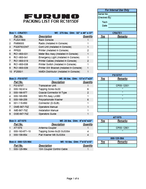
Tech Date Box 1 - CRATE1Wt: 275 lbs. Dim: 32" x 48" x 37"Part No.Description Quantity Yes Remarks 1FUSA1800Rack Console 12FM8900S Radio (Installed in Console)13FS2575CONT Cont Unit (Installed in Console)14PP520Printer (Installed in Console)25RC1-800-031Meter Box Assy (Installed in Console)16RC1-800-041Emergency Light (Installed in Console)17RC1-800-019Printer Cables (Installed in Console)28RC1-800-038Printer Switch (Installed in Console)19RC1-800-039Printer SW Bracket (Installed in Console)110IF2550/1NMEA Distributor (Installed in Console)1Box 2 - FS1575T Wt: 50 lbs. Dim: 13"x17"x23"Yes Remarks Part No.Description Quantity 1FS1575T Transceiver Unit 1CP05-120012000-162-614Tapping Screw 6x306"3000-166-977Coaxial Connector M Type 2"4000-165-859Mini Pin Assy L=3801"5000-168-259Polycarbonate Washer 6"6001-115-850Connector (D-SUB)17OME-567-70Z Operators Manual 18IME-567-70Z Installation Manual 19OSE-567-70Z Operators Guide 1Box 3 - AT1575Wt: 20 lbs. Dim: 8"x16"x22"Yes Remarks Part No.Description Quantity 1AT1575Antenna Coupler 1CP05-129012000-163-871-10Tapping Screw 6x20 SUS3044"3000-158-854Flat Washer M6 SUS3044Box 4 - 000-125-984Wt: 10 lbs. Dim: 7"x15"x15"Yes RemarksPart No.Description Quantity 1000-125-98410m Coupler Control Cable 1AT1575000-125-984PACKING LIST FOR RC1815DFCRATE1FS1575TTech Date Box 5- FELCOM18 Wt: 32 lbs Dim: 16" X 17" X 20"Yes Remarks Part No.Description Quantity 1IC218A Terminal Unit 12000-154-025Power Cable Assy 5M 13000-176-235-10Mini Keyboard 1CP16-052014100-292-140Fuse Label 1"5590-300-310Copper Strap 1"6100-369-610LAN CBL Support 1"7100-369-620Sponge for LAN 1"8000-162-608Tapping Screw 4"9000-167-183Cable Tie 150mm 2"10000-155-8317A Fuse 1CP16-0520211100-237-670Hook Loop Fastener 4"12100-237-680Hook Loop Fastener 4"13100-373-800Label 1SP16-0130114000-155-8317A Fuse 1"15000-155-827-105A Fuse 116000-809-352Distress Communications 117OME-563-51Z Operator's Manual (SSAS)118OSE-567-40Z Operator's Guide 119IME-567-40Z Installation Manual 120OME-567-40Z Operator's Manual 121000-807-330Registration for Service Activation 122000-809-353Before Delivering to Owner Notice 123000-147-004Change of Fuse Notice 124IC118/30Antenna Unit 125000-159-52330M Cable Assy 1CP16-0551126000-165-300Insulation Sleeve 1"27000-173-169Cable Tie CV-450B 5"28000-174-646Self Bonding Tape 1"29000-566-000Ground Wire Assy 30CM 1"30000-158-483Silicone Sealant 1"31000-173-370Antenna Install/Replace Document 132IC318Junction Box 1CP16-0510133000-162-605Tapping Screw M4x164PACKING LIST FOR RC1815DFFELCOM18Serial No.Checked By: Tech Date Box 6- FELCOM18 Wt: 32 lbs Dim: 16" X 17" X 20"Yes Remarks Part No.Description Quantity 1IC218A Terminal Unit 12000-154-025Power Cable Assy 5M 13000-176-235-10Mini Keyboard 1CP16-052014100-292-140Fuse Label 1"5590-300-310Copper Strap 1"6100-369-610LAN CBL Support 1"7100-369-620Sponge for LAN 1"8000-162-608Tapping Screw 4"9000-167-183Cable Tie 150mm 2"10000-155-8317A Fuse 1CP16-0520211100-237-670Hook Loop Fastener 4"12100-237-680Hook Loop Fastener 4"13100-373-800Label 1SP16-0130114000-155-8317A Fuse 1"15000-155-827-105A Fuse 116000-809-352Distress Communications 117OME-563-51Z Operator's Manual (SSAS)118OSE-567-40Z Operator's Guide 119IME-567-40Z Installation Manual 120OME-567-40Z Operator's Manual 121000-807-330Registration for Service Activation 122000-809-353Before Delivering to Owner Notice 123000-147-004Change of Fuse Notice 124IC118/30Antenna Unit 125000-159-52330M Cable Assy 1CP16-0551126000-165-300Insulation Sleeve 1"27000-173-169Cable Tie CV-450B 5"28000-174-646Self Bonding Tape 1"29000-566-000Ground Wire Assy 30CM 1"30000-158-483Silicone Sealant 1"31000-173-370Antenna Install/Replace Document 132IC318Junction Box 1CP16-0510133000-162-605Tapping Screw M4x164For Internal Use Only PACKING LIST FOR RC1815DFFELCOM18Box 7 - FM-8900Wt: 14lbs Dim: 16"x15"x9" Part No.Description Quantity 1FM-8900Marine VHF Radiotelephone 12Operator's Manual 13Operator's Guide 14Installation Manual 15Procedure for Distress6Transmission on VHF FM-890017001-174-170-00Installation Materials 18001-174-160-00Spare Parts 19005-951-920-00Accessories- Handset 110000-021-362-00Handset 411005-951-790-00Handset Bracket 412000-176-274-10Power Cable 1PACKING LIST FOR RC1815DF。
柯达工业X射线胶片M100说明书

December 2006 • TI-2434TECHNICAL DATA / NON-DESTRUCTIVE TESTINGKODAK INDUSTREX M100 FilmFEATURES / CUSTOMER PRODUCT SPECIFICATIONS•For critical radiography, especially with high voltage x-rays and gamma rays •Can be used with direct x-rays or with lead foil screens •For manual or machine processing•Medium speed, very high contrast, high definition (excellent sensitivity)•Very fine grainTHICKNESSCLASSIFICATIONEXPOSURE CONDITIONS: 8 mm Copper Filtration, HVL 3.5 mm Copper (220 kV), Lead screens.AVAILABLE PACKAGING FORMATSSheet FilmNon-Interleaved (NIF) (M100-1): This form of packaging is generally supplied in packs of 100 sheets, and is for use when film is to be loaded into metal or plastic cassettes, or exposure holders, with or without lead screens.Pb Contactpak (M100-7): In INDUSTREX Pb Contactpak packaging, industrial X-ray films are placed between two lead screens, which absorb the undesirable longerwavelengths of scattered radiation. The lead screens also intensify the image by emitting secondary electrons caused by the radiographic exposure. Lead screens are made up of a thin lead layer of 27-microns (1-mil)Base / Support 0.18 mm (7.0 mils)Emulsion 25 microns (1.0 mil); 12.5 microns each side Overcoat 10 microns (0.4 mil); 5 microns each side T otal0.22 mm (8.4 mils)KODAK INDUSTREX 43IC ProcessorKODAK INDUSTREX Single Part Developer Replenisher,8 minutes at 79°F (26°C)EN-584-1C2ASTM 1815-96Class I ISO 11699-1T1comprising a low percentage of antimony and tin,laminated on a paper sheet. The lead foil features a protective overcoat which prevents human contact with the lead, protects the film from potential "lead smudge" artifacts, and also provides static protection as the film and screens are separated.Lead Screens*Thickness not drawn to scale.The film type is identified on the package as well as embossed on the film itself. The package is laser-scored for easy opening, and has a butt edge which is invaluable for accurate positioning in difficult situations where the image needs to fall right up to the edge of the pack. The sandwich of lead screens and film is vacuum sealed in a lighttight, water and oil resistant, ready-to-expose flexible package, providing superb film/screen contact for optimum image quality.READY-PACK II Film (M100-2): These films areindividually vacuum sealed in lighttight, water-resistant, flexible packages. The package is laser-scored for easy opening. The film type is identified on the package as well as embossed on the film itself. The package has a butt edge which is invaluable for accurate positioning in difficult situations where the image needs to fall right up to the edge of the pack.Roll FilmREADY-PACK (M100-381): The film is supplied in a long, lighttight roll sandwiched between two yellow-black paper polyethylene layers. The rolls are of 60- or 100-metre lengths in a variety of widths. The film is provided in a dispenser box and is cut to length by the user in a darkroom.NIF bulk roll (M100-359): The film is supplied on acardboard core in rolls 150 metres long in three widths: 60 mm, 70 mm and 100 mm. The film must be loaded into a cassette in a darkroom.LayerApproximate Thicknessprotective overcoat1.5 micron lead *27.5 micronspaper *70 micronsSAFELIGHT RECOMMENDATIONSUse a KODAK LED Safelight (660 nm red) or a red safelight filter (i.e. KODAK 1, 1A, or 2 Safelight Filter) in a suitable safelight lamp equipped with a 15-watt bulb. Keep the film at least 4 feet (1.2 metres) from the safelight.Note: Other safelight filters (i.e. KODAK 8 and GBX-2 Safelight Filter) which block radiation at 550nm and shorter wavelengths are also suitable for use.STORAGE AND HANDLINGHandle film carefully to avoid physical strains such as pressure, creasing, or buckling.It is important to realize that meeting the chemical and physical requirements does not by itself ensure thatrecords will not deteriorate. It is essential to provide proper storage conditions. ASTM E 1254 gives details of storage conditions. ISO 18911 and ISO 18902 give, for processed films, recommended storage conditions and specifications for the respective enclosure materials.Unexposed50 to 70°F (10 to 21°C), 30 to 50% RH. Properly shield from x-rays, gamma rays, or other penetrating radiation.ExposedKeep cool, dry, and properly shielded from penetrating radiation. Process as soon as possible after exposure.Processed60 to 80°F (15 to 27°C), 30 to 50% RH.RELATIVE EXPOSUREKODAK INDUSTREX Films for Various Processing ConditionsEXPOSURE CONDITIONS: 8 mm Copper Filtration, HVL 3.5 mm Copper (220 kV), Lead screens* M100 Film in 8 min 79°F (26°C) cycle is assigned a relative exposure of 1.KODAKINDUSTREX FilmsKODAK INDUSTREX Processor KODAK INDUSTREX Chemicals8 min 79°F (26°C)DR50 1.6M100* 1.0MX1250.6T2000.4AA 4000.3HS8000.15RELATIVE EXPOSURE FOR VARIOUS ENERGY LEVELSFor each exposure condition, M100 Film is assigned a relative exposure of 1.00.KODAK INDUSTREX Processor, 8 minute 79°F (26°C) cycle.* In accordance with ISO 7004 standard. Without lead screens † In accordance with ISO 7004 standard - EN 584-1 Lead screens ‡ 8 mm Copper filtration. 100/200 microns lead screens § 100/200 microns lead screensAUTOMATIC PROCESSINGNotice: Observe precautionary information on product labels and on the Material Safety Data Sheets.See Kodak publication TI-2621, Processing KODAKINDUSTREX Films , for additional information on automatic processing.EXPOSURE CONDITIONS: 200/220 kV, ISO/ANSI/EN Conditions, KODAK INDUSTREX ChemicalsFilm Characteristics (Sensitometric)* Contrast calculated between net densities of 1.5 and 3.5.Recommended Replenishment RatesThe consistency of the radiographic quality is related to the accurate adjustment of the replenishment rate.Replenishment should maintain the chemical equilibrium, replacing the components used by the film.* For optimum archivability, a 10% increase in fixer replenishment rate may bedesirable.INDUSTREXFilms ISO 120kV *EN 220kV †Iridium ‡Cobalt §DR50 2.3 1.6 1.6 1.6M100 1.0 1.0 1.0 1.0MX1250.70.60.60.6T2000.40.40.40.3AA4000.30.30.20.2HS800—0.15——KODAK INDUSTREX Processor / Cycle Base + Fog Contrast *M43IC, 8 min 79°F (26°C)0.19 5.4M43IC, 5 min 86°F (30°C)0.19 5.25M35, 10.5 min 86°F (30°C)0.194.8Solution Replenishment Volumeper 35 x 43 cm (14 x 17 inch) sheetper m 2Developer 100 mL 665 mL Fixer180 mL *1200 mLWashing and DryingWashing: Follow the processor manufacturer'srecommendation for wash flow rate, or adjust flow to achieve the equivalent of the wash tank capacity every five minutes, or twelve tank volumes per hour. Insufficient wash flow can adversely affect the life expectancy of processed radiographs. Wash flow rate should be increased if chemical spot tests or other analyticalmethods reveal a high level of retained chemicals in the processed film. For best results, the wash tank should be drained daily and left empty when not in use.Drying: Follow the processor manufacturer'srecommendation for dryer settings. In general, the dryer should be set to a temperature slightly above (3°C/5°F) the lowest temperature required to eliminate any signs of tackiness in films exiting the dryer.MANUAL PROCESSINGNotice: Observe precautionary information on product labels and on the Material Safety Data Sheets.See Kodak publication TI-2643, Guide to Manual Processing of NDT Films , for additional information on manual processing.Film Characteristics (Sensitometric)* Contrast calculated between net densities of 1.5 and 3.5.Development ConditionsBase + Fog Contrast *5 min 68° (20°C)0.19 5.03 min 75° (24°C)0.195.3DevelopmentDevelop with rack and tank, using properly replenished solutions.•Remove film and hanger 5 seconds before end of development. DO NOT ALLOW EXCESS DEVELOPER TO DRAIN BACK INTO THE TANK. Normally this will carry out the proper amount of solution to permit correct replenishment.•Use floating covers on developer tanks to reduce oxidation and evaporation; store developer replenisher in a closed container. •Fill the developer and fixer tank to its original level each morning with developer or fixer replenisher solution (topping off).•Discard solution after adding two tank volumes of replenisher to tank, or at least once a month, and refill with fresh solution.Stop, Fix, Wash and Dry StepsStop baths check development, prevent most spots or streaks, and prolong the life of the fixing bath.Immerse the film in fixer for 3 to 6 minutes , agitating for 5 seconds every 30 seconds . Film should remain in fixer for twice the time it takes to "clear" it (when the milky look disappears). Never fix film for less than 3 minutes.KODAK Hypo Clearing Agent may be used following the fixer to reduce washing time and conserve water. First rinse films in running water for 30 seconds, the use Hypo Clearing Agent for 1 to 2 minutes, followed by a final running water wash for 5 minutes.T emperature RecommendedT ime(Minutes)Agitation KODAK INDUSTREX Single Part Developer Replenisher68°F (20°C)72°F (22°C)75°F (24°C)79°F (26°C)5432Intermittent (5 seconds every 30 seconds)T emperatureRecommendedT ime Agitation KODAK Indicator Stop Bath, or acetic acid (diluted to 3.5%) solution 60 to 85°F 16 to 30°C30 to 60 secondsContinuous, ModerateKODAK Rapid Fixer, KODAK INDUSTREX Manual Fixer, or KODAKINDUSTREX LO Fixer and Replenisher 60 to 85°F 16 to 30°C3 to 6 minutes, or twice the clearing timeVigorous for 15 seconds, then intermittent (5 sec every 30 sec)Running water wash(8 volumechanges per hour)60 to 85°F 16 to 30°C 10 to 30MinutesKODAK INDUSTREX M100 FilmAerial and Industrial MarketsEASTMAN KODAK COMPANY • ROCHESTER, NY 14650-0505Revised 12-06Printed in U.S.A.KODAK INDUSTREX M100 Film KODAK Publication No. TI-2434NOTICE: While the sensitometric data in this publication are typical of production coatings, they do notrepresent standards which must be met by Kodak. Varying storage, exposure, and processing conditions will affect results. The company reserves the right to change and improve product characteristics at any time.To minimize water spots and drying marks, use KODAK PHOTO-FLO Solution after washing.Dry in a dust-free area at room temperature or in a suitable drying cabinet. Temperature not to exceed 120°F (50°C).Recommended Replenishment RatesMaintain chemical activity and solution level in the developer tank by adding 100 mL (3.38 fluid ounces) of replenisher according to instructions for each 14 x 17-inch (35 x 43 cm) film processed. Stir vigorously after each addition. Replenish the fixer tank at the rate of 180 mL (6 fluid ounces) per 35 x 43 cm (14 x 17 in) sheet of film processed.CURVESCharacteristic Curves, Manual ProcessingCharacteristic Curves, Machine ProcessingKodak, Industrex, Ready-Pack, and Photo-flo are trademarks.。
KIT-Z100 快速入门指南说明书

Scan for full manualKIT-Z100 Quick Start GuideThis guide helps you install and use your KIT-Z100 for the first time.Go to /downloads/KIT-Z100 to download the latest user manual and check if firmware upgrades are available.Step 1: Check what’s in the packageECU-Z1001 19V DC power adapter and cord 1 Quick start guide KT-107Z/KT-107ZRB (with restricted BW, up to 5.35GHz) 1 5.2V power adapter and cord Tabletop mount On-wall mount unit 1 C-USB/Micro B cableInstallation screwsPanel Mount plate1 right-angle OTG USB cableStep 2: Get to know your KIT-Z100ECU-Z100KT-107Z/KT-107ZRBBoth Table-top mount and wall mount include the following connectors: • A power connector, when notusing the PoE Ethernet port. • PoE RJ-45 Ethernet Port toconnect to an Ethernet cable. • A USB connector:▪ For the table-top mount, aMicro-USB port, forconnecting an external USB device (for example, a headset or memory disk). ▪ For the wall mount, a Type AUSB port is available using the right-angle OTG USB cable (included).Step 3: Mount ECU-Z100Install ECU-Z100 using one of the following methods:• Attach the rubber feet and place the unit on a flat surface.• Fasten a bracket (included) on each side of the unit and attach it to a flat surface(see /downloads/KIT-Z100).• Mount the unit in a rack using the recommended rack adapter(see /product/KIT-Z100).• Ensure that the environment (e.g., maximum ambient temperature &air flow) is compatible for the device. • Avoid uneven mechanical loading.• Appropriate consideration of equipment nameplate ratings should be used for avoiding overloading of the circuits.• Reliable earthing of rack-mounted equipment should be maintained.Step 4: Mount KT-107Z/KT-107ZRBMounting on a table using one of the following options:Portable Mount: place the tabletop mount on the table. Connected cables remain visible and the table remains intact. Secure Mount: secure the tabletop mount to the table as follows:1. Measure the exact location on the surface of the table where you want to install the KT-107Z/KT-107ZRB.2. Drill a hole in the table and optionally cut the cable pass-through opening according to the cut-out dimensions definedin the user manual.3. Secure the tabletop mount to the table using the M5x60 secure screw.4. Connect the Ethernet port to a PoE-enabled source. Optionally, you can connect the power adapter too (as backup).5. Replace the appropriate cover and place the KT-107Z/KT-107ZRB over the tabletop mount (the is magnetically heldin place), by first inserting the lower part of the then carefully laying the KT-107Z/KT-107ZRB in place.6. Wait for the Home-page to load and then secure the KT-107Z/KT-107ZRB to the tabletop mount from the rear side(using 2 M2x4 screws, supplied with the unit).7. Optionally, lock the tabletop mount with a Kensington locker (not supplied).Mounting on the wall:Before mounting KIT-Z100 on a wall, install an in-wall junction box (recommended boxes are listed in the user manual)1. Attach the on-wall mount unit to the installed junction box (top side up see indication arrows on unit).Connect Ethernet and/or power cables and optionally, insert the right-angle USB cable (supplied) for connecting to an adjacent external USB device.2. Screw the 4 wall-mounting screws (supplied) through the screw openings.The various screw openings fit various types of wall junction boxes.3. On the rear side of the KT-107Z/KT-107ZRB, remove the screwcover and the cover (by slightly pressing downwards and thenpulling out) and set aside.4. Attach the panel mount plate to the rear side of theKT-107Z/KT-107ZRB (using 4 M2x4 screws, supplied).5. Connect the flat cable from the on-wall mount (attached to thein-wall junction box) to the connector on the rear ofKT-107Z/KT-107ZRB.6. Hang the KT-107Z/KT-107ZRB on the wall by sliding the tabs onthe attached panel mount plate over the grooves on the on-wallmount unit.Step 5: Connect inputs and outputsAlways switch OFF the power on each device before connecting it to your KIT-Z100.To achieve specified extension distances, use the recommended Kramer cables available at/product/KIT-Z100. Using third-party cables may cause damage!Microphone and speakers can be connected to ECU-Z100 in the following ways:•Speakers can be connected via LINE OUT connector and/or USB ports.•Microphones cab be connected via MIC IN connector (via amp) and/or USB ports.•Speakerphones (combining a speaker and a microphone) can be connected via USB ports.KT-107Z/KT-107ZRB can be powered in any of the following ways:•Using the power adapter when connected by LAN (without PoE support).•Using the power adapter when connected to LAN by Wi-Fi•By PoE when connecting to Ethernet by PoE-supporting LAN.Step 6: Connect powerConnect the power cord to ECU-Z100 and plug it into the mains electricity.If required, connect the power adapter on the KT-107Z/KT-107ZRB to the Power 2-pin terminal block connector on the tabletop mount and to the mains power.Safety Instructions (See for updated safety information)Caution:•There are no operator serviceable parts inside the unit.Warning:•Use only the power cord that is supplied with the unit.•Disconnect the power and unplug the unit from the wall before installing.•Do not open the unit. High voltages can cause electrical shock! Servicing by qualified personnel only.•To ensure continuous risk protection, replace fuses only according to the rating specified on the product label which located on the bottom of the unit.Step 7: Set and operate KIT-Z100Before setting up the application on KT-107Z/KT-107ZRB, you need to acquire Zoom Rooms licenses.To set and operate the application, go to the Zoom Rooms website at /hc/en-us.To use the Zoom Rooms widget on Kramer Control, go to Zoom Rooms settings at/manuals/kramer/kramer-control/1/en/topic/zoom-room-module.。
IATA AHM目录

Airport Handling ManualEffective 1 January—31 December 201838NOTICEDISCLAIMER. The information contained in thispublication is subject to constant review in the lightof changing government requirements and regula-tions. No subscriber or other reader should act onthe basis of any such information without referringto applicable laws and regulations and/or withouttak ing appropriate professional advice. Althoughevery effort has been made to ensure accuracy, theInternational Air Transport Association shall not beheld responsible for any loss or damage caused byerrors, omissions, misprints or misinterpretation ofthe contents hereof. Furthermore, the InternationalAir Transport Association expressly disclaims anyand all liability to any person or entity, whether apurchaser of this publication or not, in respect ofanything done or omitted, and the consequencesof anything done or omitted, by any such person orentity in reliance on the contents of this publication.Opinions expressed in advertisements appearing inthis publication are the advertiser’s opinions and donot necessarily reflect those of IATA. The mentionof specific companies or products in advertisementdoes not imply that they are endorsed or recom-mended by IATA in preference to others of a simi-lar nature which are not mentioned or advertised.© International Air Transport Association. AllRights Reserved. No part of this publication maybe reproduced, recast, reformatted or trans-mitted in any form by any means, electronic ormechanical, including photocopying, record-ing or any information storage and retrieval sys-tem, without the prior written permission from:Senior Vice PresidentAirport, Passenger, Cargo and SecurityInternational Air Transport Association800 Place VictoriaP.O. Box 113Montreal, QuebecCANADA H4Z 1M1Airport Handling ManualMaterial No.: 9343-38ISBN 978-92-9229-505-9© 2017 International Air Transport Association. All rights reserved.TABLE OF CONTENTSPage Preface (xv)Introduction (xvii)General (1)AHM001Chapter0—Record of Revisions (1)AHM011Standard Classification and Numbering for Members Airport Handling Manuals (2)AHM012Office Function Designators for Airport Passenger and Baggage Handling (30)AHM020Guidelines for the Establishment of Airline Operators Committees (31)AHM021Guidelines for Establishing Aircraft Ground Times (34)AHM050Aircraft Emergency Procedures (35)AHM070E-Invoicing Standards (53)Chapter1—PASSENGER HANDLING (91)AHM100Chapter1—Record of Revisions (91)AHM110Involuntary Change of Carrier,Routing,Class or Type of Fare (92)AHM112Denied Boarding Compensation (98)AHM120Inadmissible Passengers and Deportees (99)AHM140Items Removed from a Passenger's Possession by Security Personnel (101)AHM141Hold Loading of Duty-Free Goods (102)AHM170Dangerous Goods in Passenger Baggage (103)AHM176Recommendations for the Handling of Passengers with Reduced Mobility(PRM) (105)AHM176A Acceptance and Carriage of Passengers with Reduced Mobility(PRM) (106)AHM180Carriage of Passengers with Communicable Diseases (114)AHM181General Guidelines for Passenger Agents in Case of SuspectedCommunicable Disease (115)Chapter2—BAGGAGE HANDLING (117)AHM200Chapter2—Record of Revisions (117)AHM210Local Baggage Committees (118)AHM211Airport Operating Rules (124)Airport Handling ManualPageChapter2—BAGGAGE HANDLING(continued)AHM212Interline Connecting Time Intervals—Passenger and Checked Baggage (126)AHM213Form of Interline Baggage Tags (128)AHM214Use of the10Digit Licence Plate (135)AHM215Found and Unclaimed Checked Baggage (136)AHM216On-Hand Baggage Summary Tag (138)AHM217Forwarding Mishandled Baggage (139)AHM218Dangerous Goods in Passengers'Baggage (141)AHM219Acceptance of Firearms and Other Weapons and Small Calibre Ammunition (142)AHM221Acceptance of Power Driven Wheelchairs or Other Battery Powered Mobility Aidsas Checked Baggage (143)AHM222Passenger/Baggage Reconciliation Procedures (144)AHM223Licence Plate Fallback Sortation Tags (151)AHM224Baggage Taken in Error (154)AHM225Baggage Irregularity Report (156)AHM226Tracing Unchecked Baggage and Handling Damage to Checked and UncheckedBaggage (159)AHM230Baggage Theft and Pilferage Prevention (161)AHM231Carriage of Carry-On Baggage (164)AHM232Handling of Security Removed Items (168)AHM240Baggage Codes for Identifying ULD Contents and/or Bulk-Loaded Baggage (169)Chapter3—CARGO/MAIL HANDLING (171)AHM300Chapter3—Record of Revisions (171)AHM310Preparation for Loading of Cargo (172)AHM311Securing of Load (174)AHM312Collection Sacks and Bags (177)AHM320Handling of Damaged Cargo (178)AHM321Handling of Pilfered Cargo (179)AHM322Handling Wet Cargo (180)AHM330Handling Perishable Cargo (182)AHM331Handling and Protection of Valuable Cargo (184)AHM332Handling and Stowage of Live Animals (188)AHM333Handling of Human Remains (190)Table of ContentsPageChapter3—CARGO/MAIL HANDLING(continued)AHM340Acceptance Standards for the Interchange of Transferred Unit Load Devices (191)AHM345Handling of Battery Operated Wheelchairs/Mobility AIDS as Checked Baggage (197)AHM350Mail Handling (199)AHM351Mail Documents (203)AHM353Handling of Found Mail (218)AHM354Handling of Damaged Mail (219)AHM355Mail Security (220)AHM356Mail Safety (221)AHM357Mail Irregularity Message (222)AHM360Company Mail (224)AHM380Aircraft Documents Stowage (225)AHM381Special Load—Notification to Captain(General) (226)AHM382Special Load—Notification to Captain(EDP Format and NOTOC Service) (231)AHM383Special Load—Notification to Captain(EDP NOTOC Summary) (243)AHM384NOTOC Message(NTM) (246)Chapter4—AIRCRAFT HANDLING AND LOADING (251)AHM400Chapter4—Record of Revisions (251)AHM411Provision and Carriage of Loading Accessories (252)AHM420Tagging of Unit Load Devices (253)AHM421Storage of Unit Load Devices (263)AHM422Control of Transferred Unit Load Devices (268)AHM423Unit Load Device Stock Check Message (273)AHM424Unit Load Device Control Message (275)AHM425Continued Airworthiness of Unit Load Devices (279)AHM426ULD Buildup and Breakdown (283)AHM427ULD Transportation (292)AHM430Operating of Aircraft Doors (295)AHM431Aircraft Ground Stability—Tipping (296)AHM440Potable Water Servicing (297)AHM441Aircraft Toilet Servicing (309)Airport Handling ManualPageChapter4—AIRCRAFT HANDLING AND LOADING(continued)AHM450Standardisation of Gravity Forces against which Load must be Restrained (310)AHM451Technical Malfunctions Limiting Load on Aircraft (311)AHM453Handling/Bulk Loading of Heavy Items (312)AHM454Handling and Loading of Big Overhang Items (313)AHM455Non CLS Restrained ULD (316)AHM460Guidelines for Turnround Plan (323)AHM462Safe Operating Practices in Aircraft Handling (324)AHM463Safety Considerations for Aircraft Movement Operations (337)AHM465Foreign Object Damage(FOD)Prevention Program (340)Chapter5—LOAD CONTROL (343)AHM500Chapter5—Record of Revisions (343)AHM501Terms and Definitions (345)AHM503Recommended Requirements for a New Departure Control System (351)AHM504Departure Control System Evaluation Checklist (356)AHM505Designation of Aircraft Holds,Compartments,Bays and Cabin (362)AHM510Handling/Load Information Codes to be Used on Traffic Documents and Messages (368)AHM513Aircraft Structural Loading Limitations (377)AHM514EDP Loading Instruction/Report (388)AHM515Manual Loading Instruction/Report (404)AHM516Manual Loadsheet (416)AHM517EDP Loadsheet (430)AHM518ACARS Transmitted Loadsheet (439)AHM519Balance Calculation Methods (446)AHM520Aircraft Equipped with a CG Targeting System (451)AHM530Weights for Passengers and Baggage (452)AHM531Procedure for Establishing Standard Weights for Passengers and Baggage (453)AHM533Passengers Occupying Crew Seats (459)AHM534Weight Control of Load (460)AHM536Equipment in Compartments Procedure (461)AHM537Ballast (466)Table of ContentsPageChapter5—LOAD CONTROL(continued)AHM540Aircraft Unit Load Device—Weight and Balance Control (467)AHM550Pilot in Command's Approval of the Loadsheet (468)AHM551Last Minute Changes on Loadsheet (469)AHM561Departure Control System,Carrier's Approval Procedures (471)AHM562Semi-Permanent Data Exchange Message(DEM) (473)AHM564Migration from AHM560to AHM565 (480)AHM565EDP Semi-Permanent Data Exchange for New Generation Departure Control Systems (500)AHM570Automated Information Exchange between Check-in and Load Control Systems (602)AHM571Passenger and Baggage Details for Weight and Balance Report(PWR) (608)AHM580Unit Load Device/Bulk Load Weight Statement (613)AHM581Unit Load Device/Bulk Load Weight Signal (615)AHM583Loadmessage (619)AHM587Container/Pallet Distribution Message (623)AHM588Statistical Load Summary (628)AHM590Load Control Procedures and Loading Supervision Responsibilities (631)AHM591Weight and Balance Load Control and Loading Supervision Training and Qualifications (635)Chapter6—MANAGEMENT AND SAFETY (641)AHM600Chapter6—Record of Revisions (641)AHM610Guidelines for a Safety Management System (642)AHM611Airside Personnel:Responsibilities,Training and Qualifications (657)AHM612Airside Performance Evaluation Program (664)AHM615Quality Management System (683)AHM616Human Factors Program (715)AHM619Guidelines for Producing Emergency Response Plan(s) (731)AHM620Guidelines for an Emergency Management System (733)AHM621Security Management (736)AHM633Guidelines for the Handling of Emergencies Requiring the Evacuation of an Aircraft During Ground Handling (743)AHM650Ramp Incident/Accident Reporting (745)AHM652Recommendations for Airside Safety Investigations (750)AHM660Carrier Guidelines for Calculating Aircraft Ground Accident Costs (759)Airport Handling ManualChapter7—AIRCRAFT MOVEMENT CONTROL (761)AHM700Chapter7—Record of Revisions (761)AHM710Standards for Message Formats (762)AHM711Standards for Message Corrections (764)AHM730Codes to be Used in Aircraft Movement and Diversion Messages (765)AHM731Enhanced Reporting on ATFM Delays by the Use of Sub Codes (771)AHM780Aircraft Movement Message (774)AHM781Aircraft Diversion Message (786)AHM782Fuel Monitoring Message (790)AHM783Request Information Message (795)AHM784Gate Message (797)AHM785Aircraft Initiated Movement Message(MVA) (802)AHM790Operational Aircraft Registration(OAR)Message (807)Chapter8—GROUND HANDLING AGREEMENTS (811)AHM800Chapter8—Record of Revisions (811)AHM801Introduction to and Comments on IATA Standard Ground Handling Agreement(SGHA) (812)AHM803Service Level Agreement Example (817)AHM810IATA Standard Ground Handling Agreement (828)AHM811Yellow Pages (871)AHM813Truck Handling (872)AHM815Standard Transportation Documents Service Main Agreement (873)AHM817Standard Training Agreement (887)AHM830Ground Handling Charge Note (891)AHM840Model Agreement for Electronic Data Interchange(EDI) (894)Chapter9—AIRPORT HANDLING GROUND SUPPORT EQUIPMENT SPECIFICATIONS (911)AHM900Chapter9—Record of Revisions (911)AHM901Functional Specifications (914)AHM904Aircraft Servicing Points and System Requirements (915)AIRBUS A300B2320-/B4/C4 (917)A300F4-600/-600C4 (920)A310–200/200C/300 (926)A318 (930)A319 (933)Table of ContentsPageChapter9—AIRPORT HANDLING GROUND SUPPORT EQUIPMENT SPECIFICATIONS(continued) AHM904Aircraft Doors,Servicing Points and System Requirements for the Use of Ground Support Equipment(continued)A320 (936)A321 (940)A330-200F (943)A330-300 (948)A340-200 (951)A340-300 (955)A340-500 (959)A340-600 (962)Airbus350900passenger (965)AIRBUS A380-800/-800F (996)ATR42100/200 (999)ATR72 (1000)AVRO RJ70 (1001)AVRO RJ85 (1002)AVRO RJ100 (1003)B727-200 (1004)B737–200/200C (1008)B737-300,400,-500 (1010)B737-400 (1013)B737-500 (1015)B737-600,-700,-700C (1017)B737-700 (1020)B737-800 (1022)B737-900 (1026)B747–100SF/200C/200F (1028)B747–400/400C (1030)B757–200 (1038)B757–300 (1040)Airport Handling ManualPageChapter9—AIRPORT HANDLING GROUND SUPPORT EQUIPMENT SPECIFICATIONS(continued) AHM904Aircraft Doors,Servicing Points and System Requirements for the Use of Ground Support Equipment(continued)B767—200/200ER (1041)B767—300/300ER (1044)B767—400ER (1048)B777–200/200LR (1051)B777–300/300ER (1055)Boeing787800passenger (1059)BAe ATP(J61) (1067)Bombardier CS100 (1068)Bombardier CS300 (1072)CL-65(CRJ100/200) (1076)DC8–40/50F SERIES (1077)DC8–61/61F (1079)DC8–62/62F (1081)DC8–63/63F (1083)DC9–15/21 (1085)DC9–32 (1086)DC9–41 (1087)DC9–51 (1088)DC10–10/10CF (1089)DC10–30/40,30/40CF (1091)EMBRAER EMB-135Regional Models (1092)EMBRAER EMB-145Regional Models (1094)Embraer170 (1096)Embraer175 (1098)Embraer190 (1100)Embraer195 (1102)FOKKER50(F27Mk050) (1104)FOKKER50(F27Mk0502) (1106)Chapter9—AIRPORT HANDLING GROUND SUPPORT EQUIPMENT SPECIFICATIONS(continued) AHM904Aircraft Doors,Servicing Points and System Requirements for the Use of Ground Support Equipment(continued)FOKKER70(F28Mk0070) (1108)FOKKER100(F28Mk0100) (1110)FOKKER100(F28Mk0100) (1112)IL-76T (1114)MD-11 (1116)MD–80SERIES (1118)SAAB2000 (1119)SAAB SF-340 (1120)TU-204 (1122)AHM905Reference Material for Civil Aircraft Ground Support Equipment (1125)AHM905A Cross Reference of IATA Documents with SAE,CEN,and ISO (1129)AHM909Summary of Unit Load Device Capacity and Dimensions (1131)AHM910Basic Requirements for Aircraft Ground Support Equipment (1132)AHM911Ground Support Equipment Requirements for Compatibility with Aircraft Unit Load Devices (1136)AHM912Standard Forklift Pockets Dimensions and Characteristics for Forkliftable General Support Equipment (1138)AHM913Basic Safety Requirements for Aircraft Ground Support Equipment (1140)AHM914Compatibility of Ground Support Equipment with Aircraft Types (1145)AHM915Standard Controls (1147)AHM916Basic Requirements for Towing Vehicle Interface(HITCH) (1161)AHM917Basic Minimum Preventive Maintenance Program/Schedule (1162)AHM920Functional Specification for Self-Propelled Telescopic Passenger Stairs (1164)AHM920A Functional Specification for Towed Passenger Stairs (1167)AHM921Functional Specification for Boarding/De-Boarding Vehicle for Passengers withReduced Mobility(PRM) (1169)AHM922Basic Requirements for Passenger Boarding Bridge Aircraft Interface (1174)AHM923Functional Specification for Elevating Passenger Transfer Vehicle (1180)AHM924Functional Specification for Heavy Item Lift Platform (1183)AHM925Functional Specification for a Self-Propelled Conveyor-Belt Loader (1184)AHM925A Functional Specification for a Self-Propelled Ground Based in-Plane LoadingSystem for Bulk Cargo (1187)Chapter9—AIRPORT HANDLING GROUND SUPPORT EQUIPMENT SPECIFICATIONS(continued) AHM925B Functional Specification for a Towed Conveyor-Belt Loader (1190)AHM926Functional Specification for Upper Deck Catering Vehicle (1193)AHM927Functional Specification for Main Deck Catering Vehicle (1197)AHM930Functional Specification for an Upper Deck Container/Pallet Loader (1201)AHM931Functional Specification for Lower Deck Container/Pallet Loader (1203)AHM932Functional Specification for a Main Deck Container/Pallet Loader (1206)AHM933Functional Specification of a Powered Extension Platform to Lower Deck/Container/ Pallet Loader (1209)AHM934Functional Specification for a Narrow Body Lower Deck Single Platform Loader (1211)AHM934A Functional Specification for a Single Platform Slave Loader Bed for Lower DeckLoading Operations (1213)AHM936Functional Specification for a Container Loader Transporter (1215)AHM938Functional Specification for a Large Capacity Freighter and Combi Aircraft TailStanchion (1218)AHM939Functional Specification for a Transfer Platform Lift (1220)AHM941Functional Specification for Equipment Used for Establishing the Weight of aULD/BULK Load (1222)AHM942Functional Specification for Storage Equipment Used for Unit Load Devices (1224)AHM950Functional Specification for an Airport Passenger Bus (1225)AHM951Functional Specification for a Crew Transportation Vehicle (1227)AHM953Functional Specifications for a Valuable Cargo Vehicle (1229)AHM954Functional Specification for an Aircraft Washing Machine (1230)AHM955Functional Specification for an Aircraft Nose Gear Towbar Tractor (1232)AHM956Functional Specification for Main Gear Towbarless Tractor (1235)AHM957Functional Specification for Nose Gear Towbarless Tractor (1237)AHM958Functional Specification for an Aircraft Towbar (1240)AHM960Functional Specification for Unit Load Device Transport Vehicle (1242)AHM961Functional Specification for a Roller System for Unit Load Device Transportation on Trucks (1245)AHM962Functional Specification for a Rollerised Platform for the Transportation of Twenty Foot Unit Load Devices that Interfaces with Trucks Equipped to Accept Freight ContainersComplying with ISO668:1988 (1247)AHM963Functional Specification for a Baggage/Cargo Cart (1249)AHM965Functional Specification for a Lower Deck Container Turntable Dolly (1250)AHM966Functional Specification for a Pallet Dolly (1252)Chapter9—AIRPORT HANDLING GROUND SUPPORT EQUIPMENT SPECIFICATIONS(continued) AHM967Functional Specification for a Twenty Foot Unit Load Device Dolly (1254)AHM968Functional Specification for Ramp Equipment Tractors (1256)AHM969Functional Specification for a Pallet/Container Transporter (1257)AHM970Functional Specification for a Self-Propelled Potable Water Vehicle with Rear orFront Servicing (1259)AHM971Functional Specification for a Self-Propelled Lavatory Service Vehicle with Rear orFront Servicing (1262)AHM972Functional Specifications for a Ground Power Unit for Aircraft Electrical System (1265)AHM973Functional Specification for a Towed Aircraft Ground Heater (1269)AHM974Functional Specification for Aircraft Air Conditioning(Cooling)Unit (1272)AHM975Functional Specifications for Self-Propelled Aircraft De-Icing/Anti-Icing Unit (1274)AHM976Functional Specifications for an Air Start Unit (1278)AHM977Functional Specification for a Towed De-Icing/Anti-Icing Unit (1280)AHM978Functional Specification for a Towed Lavatory Service Cart (1283)AHM979Functional Specification for a Towed Boarding/De-Boarding Device for Passengers with Reduced Mobility(PRM)for Commuter-Type Aircraft (1285)AHM980Functional Specification for a Self-Propelled Petrol/Diesel Refueling Vehicle forGround Support Equipment (1287)AHM981Functional Specification for a Towed Potable Water Service Cart (1289)AHM990Guidelines for Preventative Maintenance of Aircraft Towbars (1291)AHM994Criteria for Consideration of the Investment in Ground Support Equipment (1292)AHM995Basic Unit Load Device Handling System Requirements (1296)AHM997Functional Specification for Sub-Freezing Aircraft Air Conditioning Unit (1298)Chapter10—ENVIRONMENTAL SPECIFICATIONS FOR GROUND HANDLING OPERATIONS (1301)AHM1000Chapter10—Record of Revisions (1301)AHM1001Environmental Specifications for Ground Handling Operations (1302)AHM1002Environmental Impact on the Use of Ground Support Equipment (1303)AHM1003GSE Environmental Quality Audit (1305)AHM1004Guidelines for Calculating GSE Exhaust Emissions (1307)AHM1005Guidelines for an Environmental Management System (1308)Chapter11—GROUND OPERATIONS TRAINING PROGRAM (1311)AHM1100Chapter11—Record of Revisions (1311)AHM1110Ground Operations Training Program (1312)Appendix A—References (1347)Appendix B—Glossary (1379)Alphabetical List of AHM Titles (1387)IATA Strategic Partners..............................................................................................................................SP–1。
Fulcrum IMSAI兼容S-100微计算机系列产品说明书

and +8V supply voltages and uses on-board regulators to obtain required voltage levels.
The board edge connector has 100 pins on 0.125-inch centers, with 50 pins on each side. Except for goldplated contact fingers, circuit traces are tin-lead plated for easier, more reliable solder connections.
Front Panel
• Handsome and functional, with sharp, readable legends behind acrylic panel
• All indicators long-life LED's ... panel filter enhances contrast
Motherboard (WB20) • Documentation
Motherboard
Card-to-card spacing on the Mother Board is %-inch, except for the first position reserved for the front panel board or any other board in dedicated applications. Eight, ten, twelve and twenty slot terminated Mother Boards are available for the system, good to 10 MHz.
Sennheiser IE 100 PRO Wireless 快速使用指南说明书
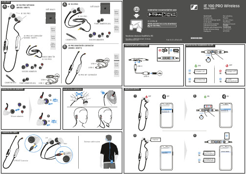
Sennheiser electronic GmbH & Co. KGAm Labor 1, 30900 Wedemark, Germany Publ. 02/22, 587443/A02IE 100 PRO WirelessModel: SEBT 1Quick Guide KurzanleitungGuide de démarrage rapide Guida rapidaInstrucciones resumidas Instruções resumidasBeknopte gebruiksaanwijzing Krótka instrukcja obsługi SnabbguideKort vejledning PikaohjeΣύντομες οδηγίεςKısa KılavuzКраткая инструкция快速指南快速使用指南 요약 안내서or online at/download IE 100 PRO_Sennheiser Documentation AppIn the boxLeftRightSoft pouchCleaning tool Safety GuideQuick Guide pliance Com-SheetSafety GuideQuick Guidepliance Com-SheetSafety GuideQuick Guide pliance Com-SheetSilicone adaptersL MSFoam adapters (M)Silicone adaptersLMSFoam adapters (M)IE PRO BT ConnectorBAUSB-AUSB-CUSB-AUSB-C1,5 HRS“Connected““Power on“3x3x3x“Power off“3sHold OFFON1x“Lostconnection““Pairing“MenuAdd Device3x3xIE PRO BT Module“Device (1) connected““Pairing successful“MenuBluetooth on Bluetooth offOFFOFF5sHoldMenuBluetooth on Bluetooth offON ONWearing the earphonesReplacing the ear adapters Optimum cable routingCharging with BT Connector Bluetooth pairingSwitching the headphones on/offChanging the cableIE PRO BT Connector1234IE 100 PROIE 100 PR OA BSoft pouchUSB-AUSB-CCleaning toolBlack cable for IE 100 PRO+Silicone adaptersLSA1xB2xIE 100 PROIE PRO BT Connector (Model: SEBT1)IE 100 PRO Wireless (Model: SEBT1)IE 100 PROIE PRO Bluetooth Connector (Model: SEBT1)CleaningMusic functions Adjusting the volume Voice assistantCall functions Specifications123x1x2xPlay/PauseNextPrevious2sHold 2sHold MUTE UNMUTE2sHold 1x1xRejectEnd1xActivating/deactivating the voice assistantAcceptModel: IE 100 PROModel: SEBT1Frequency response ImpedanceSound pressure level (SPL)Total harmonic distortion (THD)Noise attenuation Magnetized field strength Temperature range20 Hz - 18,000 Hz 20 Ω115 dB (1 kHz / 1 V rms )< 0.1 % (1 kHz, 94 B)< 26 dB 1.63 mT Model: SEBT1Bluetooth®VersionTransmission frequency Modulation Profiles Output power CodecBluetooth 5.0 compatible, class 1, BLE 2,402 Mhz to 2,480 MHz GFSK, π/4 DQPSK, 8DPSK HSP, HFP, AVRCP, A2DP 10 mW (max)SBC, aptX®, aptX® LL, AACOperation -5 °C ... +50 °C Storage-20 °C ... +70 °C Relative air humidity< 95 %Wearing style Microphone principleMicrophone frequency response Microphone sensitivity Microphone pick-up pattern (speech audio)Power supply built-in rechargeable lithium-polymer battery Bluetooth® neckband cable MEMS100 Hz - 8,000 Hz(as per ITU-T P.79) -42 dBV/Pa omni-directional3.7 V ⎓, 100 mAh USB charging 5 V ⎓, 100 mA max.Magnetic field strength 1.63 mT (with IE 100 PRO)0.23 mT (without headphone)Weightapprox. 13 gOperating time10 hrs (music playback via SBC)with rechargeable battery;240 hrs in standby mode Charging time of rechargeable batteriesapprox. 2.5 hrsTemperature rangeOperation Charging Storage+5 °C ... +40 °C ± 5 °C +10 °C ... +40 °C ± 5 °C -20 °C ... +70 °CTemperature rangeOperation Storage10 ... 80 %, non-condensing 10 ... 90 %The Bluetooth® word mark and logos are registered trademarks owned by Bluetooth SIG, Inc. and any use of such marks by Sennheiser electronic GmbH & Co. KG is under license.Information and AccessoriesApple®, IPad® and iPhone® are trade-marks of Apple Inc., registered in the U.S. and other countries. Google Play and the Google Play logo are trademarks of Google LLC.。
FUJIFILM FINEPIX XP150 160 100 110 说明书

請勿在雷雨中接觸相機的金屬部分,否則可能會因 閃電放出的感應電流而導致電擊危險。
請勿使用非指定的電池。安裝電池時,請按照指 示進行操作。 請勿加熱、改造或分解電池。請勿摔落或使電池受 到撞擊。電池不可與金屬製品一起存放。上述任何 一種行為都可能導致電池爆炸或漏液,從而引起火 災或人身傷害。 請僅使用指定用於本相機的電池或 AC 電源轉換器。 切勿在所示電壓範圍之外使用。使用其他電源可 能引起火災。 若電池漏液,電解液接觸到眼睛、皮膚或衣物,請 用清水沖洗接觸部位並立即就醫診治,或電話尋 求緊急救護。
■ 電池使用須知 若閒置不用,電池會逐漸喪失電量。 請在使用前一兩天內為電池充電。
閒置時將相機關閉可延長電池壽命。
低溫環境下電池效能會下降;電量快 耗盡的電池在寒冷條件下無法正常工 作。請將一枚充滿電的備用電池存放 在溫暖的地方並在必要時更換,或者 將電池放在口袋或其他溫暖的地方, 且僅等到拍攝時才將其插入相機。請 不要將電池與暖手用品或其他加熱裝 置直接接觸。
附件:不要使用不是影音產品製造 廠商所建議的附件,否則可能會導 致危險。
水份和濕氣:不要在靠近有水的地方 使用這個影音產品 — 例如,靠近浴 缸、洗臉盆、洗碗槽或洗衣盆、在潮 濕的地下室中使用、或靠近游泳池及 類似的地方(防水產品除外)。
電源線保護:電源線應妥善佈設使它 不會被踐踏或被其他物品夾壓,尤其 應特別注意插頭、收線裝置處、以及 從機體引出的位置的電線。
v
安全須知
電池及電源 附註:請檢查您相機所使用的電池類 型並閱讀相應章節。
下文說明電池的正確用法以及延長使 用壽命的方法。電池的不正確使用會 縮短電池壽命或者造成電池漏液、過 熱、引發火災或爆炸。
PhiClock PCIe 9FGV1001、9FGV1002、9FGV1004 芯片评估板用户指南

EVK9FGV1001EVK9FGV1002EVK9FGV1004IntroductionThe evaluation board is designed to help the customer evaluate the 9FGV1001, 9FGV1002, and 9FGV1004 devices. When the board is connected to a PC running IDT Timing Commander ™ software through USB, the device can be configured and programmed to generate different combinations of frequencies.Board OverviewUse Figure 1 and Table 1 to identify: power supply jacks, USB connector, input and output frequency SMA connectors.Figure 1. Evaluation Board Overview10111213101234567899FGV1001, 9FGV1002, and 9FGV1004 PhiClock™ PCIe Evaluation BoardUser Guide9FGV1001, 9FGV1002, and 9FGV1004 PhiClock™ PCIe Evaluation Board User GuideBoard Power SupplyThe evaluation board uses jumpers E1–E6 to set the power supply voltages for various V DD pins. The 4-way jumpers can select 3 different voltages from regulators that use power from the USB port. Selection #2 is the jack for connecting a bench power supply.E1: Power supply for the REF outputs. The E1 voltage also determines the LVCMOS output levels of the REF0 and REF1 outputs.E2: Power supply for the OUT0 output driver.E3: Power supply for the OUT1 output driver.E4: Power supply for the analog (V DDA ) and digital (V DDD ) core V DD pins.E5: Power supply for the OUT2 output driver.E6: Power supply for the OUT3 output driver.See 9FGV100x Evaluation Board Schematics (Figure 5–Figure 8) for detailed information.Table 1. Evaluation Board Pins and FunctionsLabel NumberNameOn-board Connector LabelFunction1I2C Interface ConnectorJ2Alternative I 2C interface connector for Aardvark.IDT Timing Commander can also use Aardvark.2USB Connector J6Connect this USB to your PC to run IDT Timing Commander.The board can be powered from the USB port.3Output Power Supply Jack J3Connect to 1.8V, 2.5V or 3.3V for the output voltage of the device.4Core Power Supply JackJ4Connect to 1.8V, 2.5V or 3.3V for the core voltage of the device.5Ground Jack J5Connect to ground of power supply.6Differential Output 1S7 and S10Can be a differential pair, or two single-ended outputs.Available logic types: LVCMOS, LVDS and LP-HCSL.7Differential Output 2S6 and S9Can be a differential pair, or two single-ended outputs.Available logic types: LVCMOS, LVDS and LP-HCSL.8Differential Output 3S5 and S8Can be a differential pair, or two single-ended outputs.Available logic types: LVCMOS, LVDS and LP-HCSL.9Reference Output 0S1Reference or buffered output from the crystal.10Power Supply VoltageSelector E1, E2, E3, E4, E5, E6VDD_REFP1, VDDO_0, VDDO_1, four-way headers used to select a power supply voltage. Connect the center pin to one of the 4 surrounding pins to select a voltage or a source.11Reference Output 1S2Reference or buffered output from the crystal.12Differential Output 0S3 and S4Can be a differential pair, or two single-ended outputs.Available logic types: LVCMOS, LVDS and LP-HCSL.13DIP SwitchU2Used to control certain pins like OEA, OEB, SEL0, SEL1 and I 2C versus Hardware Select mode.9FGV1001, 9FGV1002, and 9FGV1004 PhiClock™ PCIe Evaluation Board User GuideDIP Switch (U2)Refer to Figure 2 and Table 2 for the DIP switch settings and functions.Figure 2. DIP Switch (U2)Interfacing with a Computer to Run Timing CommanderAs shown in Figure 3, jumpers JP1 and JP2 are installed to use the FTDI chip U6 for connecting to the computer with the USB port J6. The U6 chip translates USB to I 2C.When using Aardvark, remove jumpers JP1 and JP2 and connect the Aardvark to connector J2. Default I 2C device address for the 9FGV100x is 0x68.Miscellaneous interfaces can connect to J2 pin 1 for the Serial Clock and to J2 pin 3 for the Serial Data signal. J2 pin 2 can be used as ground, but any other ground pin will also work.When OTP in the 9FGV100x devices is burned with multiple configurations, JP1 and JP2 can be applied in JP3 position respectively to connect the SEL0 and SEL1 switches in U2. Move switch 8 to “+” and power-up the 9FGV100x in Hardware Select mode. This enables changing between 4 configurations with SEL0/1.Table 2. DIP Switch SettingsSwitch Number Function1 = OEA See datasheet.2 = OEB3 = SEL0Select 1 of4 pre-programmed configurations when in Hardware Select mode. Also see switch 8.4 = SEL15Not used.6Not used.7Not used.8 = ModeSelects operating mode at power-up.“-” or “O” selects I 2C mode.“+” selects Hardware Select mode.9FGV1001, 9FGV1002, and 9FGV1004 PhiClock™ PCIe Evaluation Board User Guide Figure 3. Connecting to a Computer via USB Port J6On-board CrystalA 25MHz crystal is installed on the board and is used as the reference frequency. The board can also be modified to insert an external reference clock into the XIN pin using SMA connector S11. When using an external reference clock, additional components need to be assembled and the crystal needs to be removed.Output TerminationsEach differential output has a pair of SMA connectors to connect to a 50Ω coax. It is recommended to combine the two signals using a balun or splitter/combiner device when measuring jitter or phase noise. The circuit at the SMA connectors is shown in Figure 4.Figure 4. SMA Connectors Circuit9FGV1001, 9FGV1002, and 9FGV1004 PhiClock™ PCIe Evaluation Board User Guide The circuit is designed for maximum flexibility when testing all possible logic types. Default assembly uses a 0.1μF capacitor in place of R14 and R16, and the short across R14 and R16 is cut. No other devices are assembled. This simple AC-coupled configuration allows for testing phase noise and jitter of all possible logic types. The circuit can be modified for custom tests. TP3 is a position to place a differential FET probe.Operating Instructions1.Set all jumpers for power supply choices (E1–E6), interface choices (JP1 and JP2), and set the U2 switches.2.Connect an interface: USB or I2C.3.In the case of an I2C interface, also connect external power supply to jacks J3, J4 and J5.4.Start Timing Commander for either USB or Aardvark.a.Start new configuration or load TCS file for existing configuration.b.Choose PhiClock personality.c.For Aardvark, click to select Aardvark “Connection Interface”.d.For a new configuration, prepare all settings.e.Click to connect to the 9FGV100x device. Top right should turn green.f.Click to write all settings to the 9FGV100x device.g.It should now be possible to measure clocks on outputs.h.While connected, each change to the settings will be written to the 9FGV100x immediately and can be observed at the clock outputs.9FGV1001, 9FGV1002, and 9FGV1004 PhiClock™ PCIe Evaluation Board User Guide Schematics9FGV1001, 9FGV1002, and 9FGV1004 PhiClock™ PCIe Evaluation Board User Guide Figure 6. 9FGV100x Evaluation Board Schematic – page 29FGV1001, 9FGV1002, and 9FGV1004 PhiClock™ PCIe Evaluation Board User Guide Figure 7. 9FGV100x Evaluation Board Schematic – page 39FGV1001, 9FGV1002, and 9FGV1004 PhiClock™ PCIe Evaluation Board User Guide Figure 8. 9FGV100x Evaluation Board Schematic – page 410©2018 Integrated Device Technology, Inc.March 1, 2018DISCLAIMER Integrated Device Technology, Inc. (IDT) and its affiliated companies (herein referred to as “IDT”) reserve the right to modify the products and/or specifications described herein at any time,without notice, at IDT’s sole discretion. Performance specifications and operating parameters of the described products are determined in an independent state and are not guaranteed to perform the same way when installed in customer products. The information contained herein is provided without representation or warranty of any kind, whether express or implied, including, but not limited to, the suitability of IDT's products for any particular purpose, an implied warranty of merchantability, or non-infringement of the intellectual property rights of others. This document is presented only as a guide and does not convey any license under intellectual property rights of IDT or any third parties.IDT's products are not intended for use in applications involving extreme environmental conditions or in life support systems or similar devices where the failure or malfunction of an IDT product can be rea-sonably expected to significantly affect the health or safety of users. Anyone using an IDT product in such a manner does so at their own risk, absent an express, written agreement by IDT.Integrated Device Technology, IDT and the IDT logo are trademarks or registered trademarks of IDT and its subsidiaries in the United States and other countries. Other trademarks used herein are the property of IDT or their respective third party owners. For datasheet type definitions and a glossary of common terms, visit /go/glossary . Integrated Device Technology, Inc.. All rights reserved.Tech Support/go/supportSales 1-800-345-7015 or 408-284-8200 Fax: /go/sales Corporate Headquarters 6024 Silver Creek Valley RoadSan Jose, CA 95138 USA 9FGV1001, 9FGV1002, and 9FGV1004 PhiClock™ PCIe Evaluation Board User GuideOrdering InformationRevision History Orderable Part NumberDescriptionEVK9FGV1001Evaluation board with all differential outputs AC coupled.EVK9FGV1002EVK9FGV1004Revision DateDescription of ChangeMarch 1, 2018Initial release.EVK9FGV1001EVK9FGV1002EVK9FGV1004。
Freefly ALTA 8 无人机说明书

SPECIFICATIONSDIMENSIONS1325 mm Unfolded Diameter(does not include Props)Folded Diameter660 mm (does not include Props)Height to base of Toad In The Hole (TITH)263 mmPOWERPLANTNumber of Motors8 Motor Type Direct Drive 3-Phase PMAC Outrunner Motor Make and Model Freefly F45 Motor Max Continuous Power Output350 W950 W Motor Max InstantaneousPeak Power OutputMaximum RPM (flat rated)6300 RPM Equivalent Kv384 Electronic Speed Controller Freefly Silent-Drive Sine Wave ESCPROPELLERSMake and Model Freefly ALTA Propeller Material Carbon fiber with balsa core Propeller Orientation(4) CW and (4) CCW Props Propeller Type18 × 6 FoldingBATTERYNominal Battery Voltage6S / 22.2V Maximum Battery Size (GroundView)240 × 175 × 80 mm Maximum Battery Size (SkyView)220 x 156 x 64 mm Maximum Battery Quantity 2 Battery Packs (Parallel) Minimum Battery Quantity 2 Battery Packs (Parallel) Battery Connectors2× EC5 (Parallel)250A / 500A Peak Required Minimum BatteryDischarge Rating (Per Pack)WEIGHTSMaximum Gross for Takeoff118.1 kg (40.0 lbs) Maximum Useful Load212.0 kg (26.4 lbs) Maximum Payload39.1 kg (20.0 lbs) Typical Standard Empty Weight: 6.2 kg (13.6 lbs)Always refer to the following aircraft limitations section forcomplete information on allowable maximum gross weightsat different altitudes and temperatures before any flight.SPECIFIC LOADINGSTypical Specific Power4145 W/kg Thrust Ratio at MTOW1 1.85 : 11 At sea level, ISA. Refer to the Weight Limitations section for complete loading information.2 Top and bottom mount. Includes batteries.3 Payload weight top or bottom mount. Battery weight not included and mounted on opposite side from payload.4 At MTOW, sea level, ISA.FLIGHT CONTROLLERModel Name Freefly SYNAPSE flight controller Flight Modes Manual, Height Mode, Position Mode(Classic, Kinematic), Return-to-Home(RTH), Autoland, Orbit Mode Supported Inputs:DSMX, DSM2, S.Bus,S.Bus2, PPM, FPV SD Supported Radios Futaba S.Bus & S.Bus2, DSMX,DSM2 (Spektrum/JR), PPM,PPM Invert, PPM Graupner Supported Radio ControllerTelemetry SystemsFutaba w/ built-in voltage sense portMinimum Radio ControllerChannels Required5 Supported GNSS GPS, GLONASS, Galileo Supported SBAS QZSS, WAAS, EGNOS, MSAS First-Person View SystemVideo FormatsNTSC, PALSupported First-Person View TransmittersSkyzone, BOSCAM, ImmersionRC, Fat SharkSupported First-Person View Cameras Ready Made RC(RMRC-700XVN Recommended) First-Person View OSD Telemetry User Configurable Installed Transceivers Wi-Fi 2.4 GHz b/g/n Data Logging Rate25 HzLIGHTING AND INDICATIONStatus Light 1 Watt Red, 1 Watt White LED Orientation Lights3-Watt RGB LED Orientation Light Color Options Red, Yellow, Blue, Purple,Green, White, OffISOLATION SYSTEMVibration Isolation System O-Rings Option 1: Soft / Light Payloads Red O-Rings Option 2: Medium / Medium Payloads Teal O-Rings Option 3: Stiff / Heavy Payloads Black O-RingsPAYLOAD MOUNTINGMounting Locations Bottom and Top Mount Mounting System Freefly Toad In The Hole(TITH) Quick Release FPV Camera Mount Between Booms 8 & 1 FPV Transmitter Mount Boom 2NOTEThese limitations are advisory in nature and do not extend orrestrict limitations provided by Governing Aviation Authorities. POWERPLANT LIMITATIONSMaximum RPM6300 RPM Maximum Battery Voltage25.2 Volts Minimum Average Battery Voltage19.2 VoltsENVIRONMENTAL LIMITATIONSDo not fly ALTA 8 in temperatures exceeding 45ºC (113ºF) or below -20ºC(-4ºF).5FLIGHT CONTROLLER LIMITSMaximum Pitch/Roll Angle45°Maximum Yaw Rate150° / second5 Battery temperature ratings must be observed.WEIGHT LIMITSMaximum Payload9.1 kg (20.0 lbs)Maximum Takeoff WeightSee following tableA L T A 8 A L L O W AB L E G R O S S W E I G H TA s a l t i t u d e a n d t e m p e r a t u r e i n c r e a s e , t h e d e n s i t y o f t h e a i r d e c r e a s e s . C o n s e q u e n t l y , A L T A 8’s t h r u s t w i l l d e c r e a s e . T h e f o l l o w i n g t a b l e d e s c r i b e s m a x i m u m g r o s s w e i g h t l i m i t s w i t h r e s p e c t t o a l t i t u d e a n d t e m p e r a t u r e .。
MT-100电子产品使用说明书

MT-100Motorcycle Tracking DeviceUSER MANUALa c k i n g T h e W o r l d .co mGeneral NotesTrackingTheWorld offers this information as a service to its customers, to support application and engineering efforts that use the products designed by TrackingTheWorld. The information provided is based upon requirements specifically provided to TrackingTheWorld by the customers. TrackingTheWorld has not undertaken any independent search for additional relevant information, including any information that may be in the customer’s possession. Furthermore, system validation of this product designed by TrackingTheWorld within a larger electronic system remains the respon sibility of the customer or the customer’s system integrator. All specifications supplied herein are subject to change.CopyrightThis document contains proprietary technical information which is the property of TrackingTheWorld, copying of this document and giving it to others and the using or communication of the contents thereof, are forbidden without express authority. Offenders are liable to the payment of damages. All rights reserved in the event of grant of a patent or the registration of a utility model or design. All specification supplied herein are subject to change without notice at any time.Copyright © TrackingTheWorld 2016For More Information: Please contact TrackingTheWorld, 1633 Bayshore Highway, Suite 390, Burlingame, CA. 94010, USA Phone: +1.650.692.8100 – Email: *************************– Website: ContentsContents (3)Table Index (4)Figure Index (5)1. Introduction (7)1.1. Reference (7)1.2. Terms and Abbreviations (7)2. Product Overview (8)2.1. Appearance (8)2.2. Parts List (8)2.3. Interface Definition (9)3. Getting Started (10)3.1. Installing a SIM Card (10)3.2. Switch the set on/off (10)3.3. Reset Key (11)3.4. USB connector (11)3.5. Power Connection (11)3.6. Ignition Detection (12)3.7. Digital Input (12)3.8. Analog Input (13)3.9. Digital Output (13)3.10. Relay Output (14)3.11. Device Status LED (15)For More Information: Please contact TrackingTheWorld, 1633 Bayshore Highway, Suite 390, Burlingame, CA. 94010, USA Phone: +1.650.692.8100 – Email: *************************– Website: Table 1: MT-100 Protocol Reference (7)Table 2: Terms and Abbreviations (7)Table 3: Part List (8)Table 4: Description of MT-100 User Cable (9)Table 5: Electrical Characteristics of Ignition Detection (12)Table 6: Electrical Characteristics of the digital inputs (12)Table 7: Electrical Characteristics of Digital Output (13)Table 8: Definition of Device status and LED (16)For More Information: Please contact TrackingTheWorld, 1633 Bayshore Highway, Suite 390, Burlingame, CA. 94010, USA Phone: +1.650.692.8100 – Email: *************************– Website: Figure 1.Appearance of MT-100 (8)Figure 2.SIM Card Installation (10)Figure 3.Typical Power Connection (11)Figure 4.Typical Ignition Detection (12)Figure 5.Typical Digital Input Connection (13)Figure 6.Typical Analog Input Connection (13)Figure 7.Typical Connection with Siren (14)Figure 8.Typical Connection with Relay (14)Figure 9.MT-100 LED on the Case (15)For More Information: Please contact TrackingTheWorld, 1633 Bayshore Highway, Suite 390, Burlingame, CA. 94010, USA Phone: +1.650.692.8100 – Email: *************************– Website: For More Information: Please contact TrackingTheWorld, 1633 Bayshore Highway, Suite 390, Burlingame, CA. 94010, USA Phone: +1.650.692.8100 – Email: *************************– Website: 1. IntroductionThe MT-100 is a powerful GPS locator designed for vehicle or asset tracking. It has superior receiver sensitivity, fast TTFF (Time to First Fix) and supports Quad-Band GSM frequencies 850/900/1800/1900, its location can be monitored in real time or be periodically tracked by a backend server or other specified terminals. The MT-100 has multiple input/output interfaces that can be used for monitoring or controlling external devices. Based on the integrated @Track protocol, the MT-100 can communicate with a backend server through the GPRS/GSM network to transfer reports of Emergency, geo-fence boundary crossings, low backup battery or scheduled GPS position as well as many other useful functions. Users can also use MT-100 to monitor the status of a vehicle and control the vehicle by its external relay output. System Integrators can easily setup their tracking systems based on the full-featured @Track protocol.This device complies with part 15B, part 22 and part 24 of the FCC rules. Operation is subject to the following two conditions: (1) this device may not cause harmful interference (2) this device must accept any interference, including interference that may cause undesired operation.1.1.Reference1.2.Terms and AbbreviationsFor More Information: Please contact TrackingTheWorld, 1633 Bayshore Highway, Suite 390, Burlingame, CA. 94010, USA Phone: +1.650.692.8100 – Email: *************************– Website: Copyright © TrackingTheWorld. All rights reserved. Information in this publication supersedes that in all previously published material. Specification and price2. Product Overview2.1.AppearanceFigure 1. Appearance of MT-1002.2.Parts ListPictureFor More Information: Please contact TrackingTheWorld, 1633 Bayshore Highway, Suite 390, Burlingame, CA. 94010, USA Phone: +1.650.692.8100 – Email: *************************– Website: Copyright © TrackingTheWorld. All rights reserved. Information in this publication supersedes that in all previously published material. Specification and price2.3.Interface DefinitionThere are 8 wires on MT-100 User Cable which contain the connection for power, ignition input, digital input, analog input, siren output, cut output etc. The user cable’s definition is shown in following table.For More Information: Please contact TrackingTheWorld, 1633 Bayshore Highway, Suite 390, Burlingame, CA. 94010, USA Phone: +1.650.692.8100 – Email: *************************– Website: Copyright © TrackingTheWorld. All rights reserved. Information in this publication supersedes that in all previously published material. Specification and priceFor More Information: Please contact TrackingTheWorld, 1633 Bayshore Highway, Suite 390, Burlingame, CA. 94010, USAPhone: +1.650.692.8100 – Email: ************************* – Website: Copyright © TrackingTheWorld. All rights reserved. Information in this publication supersedes that in all previously published material. Specification and price 3. Getting Started3.1. Installing a SIM CardStep 1: Remove the cover by screwdriver.Step 2: Make sure the contact area is facing down, insert the SIM into the slot. Step 3: Install the SIM card cover.Figure 2. SIM Card Installation3.2. Switch the set on/offThere are two methods to Power on MT-100: - MT-100 external power turned on.- Connect MT-100 to PC with user cable.When the external power or USB cable power is removed, MT-100 will switch to internal backup battery and keep on running. When internal backup battery is exhausted, MT-100 will give a report and then turn off.Note:1-External power and User USB power can be present at same time.2-For USB port current limitation, when configuring MT-100 by user cable, please let backup battery onusing.For More Information: Please contact TrackingTheWorld, 1633 Bayshore Highway, Suite 390, Burlingame, CA. 94010, USAPhone: +1.650.692.8100 – Email: ************************* – Website: Copyright © TrackingTheWorld. All rights reserved. Information in this publication supersedes that in all previously published material. Specification and price There is one method to turn off MT-100.- Remove the external power and USB power. - Press the reset key.Note:MT-100 PWR LED will off.3.3. Reset KeyThere is a reset key behind the SIM card cover. If the power wire is connected to vehicle power, the system will reboot when the key is pressed; if the system is powered by the backup battery and the power wire is not be connected to vehicle power, the system will shutdown when the key is pressed. Note:When you finished the firmware upgrade, please press the reset key to reboot the system before configuring the terminal.3.4. USB connectorThere is a USB connector on MT-100 which is beside the SIM card. With the USB connector and the DATA_CABLE_M, user can configure the system or download firmware. As long as the DATA_CABLE_M is plugged in, the system will boot.3.5. Power ConnectionThe red wire is power wire and the black wire is ground wire. The input voltage range for this device is from 8V to 32V. The device is designed to be installed in vehicles that operate on 12V or 24V systems without the need for external transformers.Figure 3. Typical Power ConnectionFor More Information: Please contact TrackingTheWorld, 1633 Bayshore Highway, Suite 390, Burlingame, CA. 94010, USAPhone: +1.650.692.8100 – Email: ************************* – Website: Copyright © TrackingTheWorld. All rights reserved. Information in this publication supersedes that in all previously published material. Specification and price 3.6. Ignition DetectionInactive0V to 3V or OpenFigure 4. Typical Ignition DetectionThe white wire is used for ignition detection. It is strongly recommended to connect this wire to ignition key “RUN” position as shown up.An alternative to connecting to the ignition switch is to find a non-permanent power source that is only available when the vehicle is running. For example the power source for the FM radio.Ignition signal can be configured to start transmitting information to backend server when ignition is on; and enter power saving mode when ignition is off.3.7. Digital InputThere is a general purpose digital input which is the blue wire on MT-100 User Cable, and it is a negative trigger. The digital input is recommended to support panic button function.The following diagram shows the recommended connection of the digital input.For More Information: Please contact TrackingTheWorld, 1633 Bayshore Highway, Suite 390, Burlingame, CA. 94010, USAPhone: +1.650.692.8100 – Email: ************************* – Website: Copyright © TrackingTheWorld. All rights reserved. Information in this publication supersedes that in all previously published material. Specification and priceFigure 5.Typical Digital Input Connection3.8. Analog InputThere is an analog input which is the green wire on MT-100 User Cable, and the analog input voltage range is from 0 to 32V. The following diagram shows the recommended connection.Figure 6. Typical Analog Input Connection3.9. Digital OutputThere is an output which is the brown wire on MT-100 User Cable. This output is used to drive a siren and the maximum drive current is 750mA. When the siren output is enabled, the voltage on the siren output is determined by the system power level, if the system power is 12V, then the siren output voltage is 12V.For More Information: Please contact TrackingTheWorld, 1633 Bayshore Highway, Suite 390, Burlingame, CA. 94010, USAPhone: +1.650.692.8100 – Email: ************************* – Website: Copyright © TrackingTheWorld. All rights reserved. Information in this publication supersedes that in all previously published material. Specification and priceFigure 7. Typical Connection with Siren3.10. Relay OutputThere is a built-in cut relay on MT-100, and it is a NC (Normal Close) type relay which maximum switching voltage is 12VDC and maximum continuous current is 20A. On MT-100 user cable one 18AWG yellow wire is connected to the relay NC contact and the other 18AWG yellow wire is connected to the relay COM contact. In certain instances the two wires will be connected together. Note:1: The relay output can be latched by the software, so even if the MT-100 is restart or power down in some cases, the relay output will not change. To use the latch function the main power and backup battery should be connected. Otherwise the relay will be always in normal close status.2: The relay works only with 12V main power. Use it when the main power is 24V may result in damaging.3: Many modern relays come with a fly-back diode pre-installed internal to the relay itself. If the relay has this diode, ensure the relay polarity is properly connected. If this diode is not internal, it should be added externally. A common diode such as a 1N4004 will work in most circumstances.Figure 8. Typical Connection with RelayFor More Information: Please contact TrackingTheWorld, 1633 Bayshore Highway, Suite 390, Burlingame, CA. 94010, USAPhone: +1.650.692.8100 – Email: ************************* – Website: Copyright © TrackingTheWorld. All rights reserved. Information in this publication supersedes that in all previously published material. Specification and price 3.11. Device Status LEDFigure 9.MT-100 LED on the CaseFor More Information: Please contact TrackingTheWorld, 1633 Bayshore Highway, Suite 390, Burlingame, CA. 94010, USAPhone: +1.650.692.8100 – Email: ************************* – Website: Copyright © TrackingTheWorld. All rights reserved. Information in this publication supersedes that in all previously published material. Specification and price Table 8: Definition of Device status and LEDNote:1 - GSM LED cannot be configured.2 - GPS LED and PWR LED can be configured to turn off after a period of time using the configuration tool3 - Fast flashing is about 60ms ON/ 780ms OFF4 - Slow flashing is about 60ms ON/ 1940ms OFF。
音频设备连接器类型说明书

Sound & Lighting Manufacturers ListHey, take a look at our new LED lites. They work anywhere standard Littlites work! MPALLEN & HEATH..................GL 3, GL 4..........................................................................18G-HIGL 2000, 3300....................................................................18GML 3000, 4000, 5000..........................................................18XR-HI 4 PINPA12-CP, PA20-CP, PA12, PA20, PA28............................18XR-HI-4GL-4000..............................................................................12X-4 (X 2)GL 2400, GL 2800..............................................................18XR-HI-4GL 3800, GL 4800..............................................................18X-HI-4MIX WIZARD......................................................................18X-HI-4 ALTAIR..................................ELECTRA SERIES............................................................12X-HI NGLEY...........................................................................XLR-4 PINSR 6000..............................................................................XLR-4 PINSR 4000..............................................................................18GAMERICAN DJ......................XDM-352, XDM 242, XDM-3633 COMMANDER................12G-HIQ2422/SX, Q-2422/X, Q-3433/SX, Q-SPANDASM STEUERUNGSTE........R2D2...................................................................................12X-HIDX33...................................................................................6G-HIAUDIO INDEPENDENCE.....PARAGON..........................................................................12 OR 18X AVOLITES.............................AZURE SHADOW, AZURE PANEL...................................12XR-HI (SPECIAL WIRING)PEARL 2000.......................................................................12X-HI (SPECIAL WIRING)SAPPHIRE 96, SAPPHIRE 2000........................................12XR-HI (SPECIAL WIRING)DIAMOND II AND III AND 4................................................12XR-HI (SPECIAL WIRING) BEHRINGER.........................EURODESK MX8000A, 9000A, UB2442FX-PRO..............18G-HIEURODESK MX3282A, 2442A...........................................12G-HIBI AMP..................................COLUMBIA & OLYMPIA.....................................................12G CARVIN.................................FX.......................................................................................12GDX1642,1642P,2442...........................................................18X-HIFX1244,1244P,1644,2444..................................................18GMX2488...............................................................................6V BNCSL24....................................................................................18X-HI CASE....................................PROFESSIONAL 1 & 2.......................................................12XR-HI CELCO..................................NAVIGATOR 3....................................................................12GAVIATOR............................................................................18XRSERIES II GOLD................................................................12GPATHFINDER.....................................................................12GPULSAR MASTER..............................................................12GEXPLORER.........................................................................12GVENTURA 1000..................................................................12XR-HIR2D2...................................................................................12X-HICOLOR TRAN.......................MADILLION 2 -3.................................................................18XR-HI 4 PININNOVATOR.......................................................................18XR-HIENCORE.............................................................................18XR-HI 4 PIN COMPULITE.........................SPARK, SABRE. OVATION4D, MICRON 4D,SPARK4D...12XR-HI OR 18XR-HISPARK TOP, SPARK, PHOTON, RAVE............................12XR-HI OR 18XR-HI CRATE..................................CSX SERIES......................................................................12G-HI OR 18G-HICREST AUDIO......................OLD STYLES......................................................................12GSP,TC,GT,LM, X-FOUR.....................................................12X-HIGTX,VX, LMX, V-12............................................................18XR-HICENTURY GT AND VX......................................................18X-HIX-EIGHT, X-MONITOR, X-VCA..........................................18X-HIHS-48+4..............................................................................18XR-HIXR-20, XR-24, XR-M...........................................................12G-HIHP-8....................................................................................18G or 18G-LEDHPW...................................................................................18G-HID & R.....................................MERLIN..............................................................................12XR-HIVISION................................................................................18XR-HIORION................................................................................18XR-HITRITON..............................................................................18XR 4 PINAXION.................................................................................18XR 4 PIN DDA.......................................CS3, CS8, CS12.................................................................18XR-HIFORUM, Q2........................................................................12X-HIINTERFACE........................................................................12GDEVON..............................SMX-2000..............................................................................12G-HI DOD...................................822XL, 822RM.......................................................................12G-HI1222XL, 1222RM....................................................................12G-HICM300, 350, 750, 1642..........................................................12G-HI DENON..............................SMX 200DJ............................................................................6G-HISMX 2000...............................................................................12G-HI DOVE.................................1Q 24.....................................................................................12GTS48D....................................................................................12G-HIE-MU..................................MP-7, XL-7, PX-7...................................................................12G-HI ELECTRA...........................18:8:2, 24:8:2, 32:8:2, 40:8:2,................................................12X-HI48:8:2.....................................................................................12X-HI ELECTRO VOICE/TELEX..BK 32 AND 43SERIES...........................................................12GEVT 52 SERIES.....................................................................12GELAN......................................................................................12-18G-HIINTERFACE CONSOLES......................................................18XR-HIVECTOR................................................................................12GPSX1000, 1600, 2200............................................................12 or 18X ETC....................................EXPRESS SERIES...............................................................18X-HIOBSESSION SERIES............................................................18XR-HI FENDER............................PX 2208..................................................................................12G-HIPX 2208D...............................................................................12G-HIPX 2212D...............................................................................12G-HIPX 2216D...............................................................................12G-HIMX-5200.................................................................................18G-HIMX 5232.................................................................................18G-HIFLYING PIG.......................WHOLE HOG 1 & 2...............................................................12XR-HI FROG.................................FROG 2, FROG 24/48, FAT FROG, FROG BOX,.................18XR-HIFAT FROG, BULL FROG, LEAP FROG, MAMBO FROG GLI.....................................PMX 7000, 8000, 9500, 9900.................................................12G-HIGEM SOUND.....................DS 9000, 9905, DSP-6PRO...................................................12G-HIDMX-6, 52..............................................................................12G-HIDMX-525, 1030 & 1070..........................................................12G-HIMX-5216,5224,5232, MP3-PRO.............................................12G-HI GEMINI..............................TURNTABLES.......................................................................12G-HIHIGH END..........................STATUS CUE,.......................................................................12 OR 18X-HIPOWER CUE.........................................................................12G INKEL.................................CMX 1664..............................................................................18G INNOVASON......................SY80......................................................................................18XR-HI-4 (X 4)SY48......................................................................................12X-HI (X 2) INTER M............................CMX 1264/1664/2464.............................................................18G-HIKENSINGTON.......................................................................18XR-HI-4 JANDS...............................ESPII-24,................................................................................18XR-HIESPII-48, 60...........................................................................18XR-HI (X2)EVENT 24..............................................................................18XR-HI (X2)EVENT 36,48, 408, 416.........................................................18XR-HI (X2)EVENT PLUS 48 AND 60......................................................18XR-HI (X2)JANDS HOG 250, 600...........................................................18XR-HI (X2)HOG 500................................................................................18XR-HIHOG 1000..............................................................................18XR-HI (X2) JUICE GOOSE...................RP-100, RP-200-L..................................................................12G LEPRECON LLC................850.........................................................................................12XR1500.......................................................................................12G1600.......................................................................................12G2000.......................................................................................18XR-HI3000.......................................................................................18XR-HILP-X24, LP-X48.....................................................................12XR-HI 4 PIN (2) LMI.....................................CH 200...................................................................................12GDESIGNER............................................................................12G LSC....................................FOCAL CONSOLES..............................................................12X-HIFOCAL TOURING DIMMING................................................12X-HIATOM.....................................................................................12XR-HIAXIOM....................................................................................12X-HIMAXIM S, MAXIM M..............................................................12XR-HIMAXIML, MAXIMXL, MAXIM XXL..........................................12XR-HI (2)LINEARTECH.................................SL-2600, SL-3100, SL-4600.......................................12G LIGHTRONICS...............................TL-2448......................................................................18G-HI LITEPUTER........................................................................................................................18G-LED MA..................................................GRAND MA, LIGHT COMMANDER 48/6..................18XR-HI (X2)LIGHT COMMANDER 24/6........................................18XR-HIGRAND MA LIGHT, GRAND MA ULTRA-LIGHT......18X-HIGRAND MA MICROLIGHT COMMANDER 12/2 19".................................18X-HILIGHT COMMANDER 12/2, SCANCOMMANDER 19"MACKIE1604...........................................................................18G-HIOTTO 1604................................................................6G-HISR 24-4 VLZ PRO, ONYX 1640...............................18G-HISR 40.8, SR 56.8,......................................................18X-HI-4 PINCFX12, 1642-VLZ, ONYX 1620.................................12G-HICFX16........................................................................18G-HICFX 18, CFX20..........................................................18G-HISR24-4 VLZ PRO.......................................................18G-HISR32-4 VLX PRO.......................................................18G-HIONYX 4880, ONYX 4080, ONYX 3280......................18X-HI-4 (X3)ONYX 2480................................................................18X-HI-4 (X2)TT24...........................................................................12X-HI-4ONYX 24-4.................................................................18G-HI MARTIN.........................................CASE CONTROLLER P1, P2....................................18XR-HICASE CONTROLLER P1+, P2+................................18XR-HICASE CONTROLLER PLAYBACK WING.................18XR-HI MIDAS.............................................MIDAS, XL3, XL200, XL250, LEGEND.....................18X-HIHERITAGE 1000, 2000, 3000...................................18XR-HIXL-4...........................................................................12G-HIVENICE,....................................................................18X-HI-4 PINVENICE,....................................................................18X-4-LED-ISOHERITAGE 4000, SIENA, VERONA..................................18XR-HIMOOG MUSIC...............................VOYAGER................................................................12X-HI MITEC.............................................EVENT......................................................................18X-HI NSI..................................................PMC, TC...................................................................18X-HIMEL, MLC, 7424, 7500, 7532....................................12, OR 18G-HI NUMARK.........................................DM 1600X..................................................................12G-HI PANASONIC...................................WR-SX-1...................................................................12G-HI PEAVEY..........................................24-FX, 32-FX.............................................................12G-HIS-24...........................................................................18G-HI PHONIC..........................................DX SERIES...............................................................18G-HI PULSAR..........................................MASTERPIECE.........................................................12G RACKMAN......................................INNOVATIONS.........................................................12G-HI RAMSA...........................................SX-1..........................................................................12G OR 12G-HIWR-S840...................................................................12 OR 18G-HIWR-C900..................................................................12 OR 18G-HIWR-4000...................................................................12 OR 18G-HIROSS MIXING................................RCS 2842..................................................................12X-HIPC 8400....................................................................12G802, 1202, 1602, 2402...............................................12GSEE FACTOR.................................LD-500, LD-1000.......................................................12XR-HI SPECIAL WIRING S OUNDCRAFT...............................EUROPA, SERIES 2, SERIES 5 MONITOR & FOH18XR-HI 4-PINVIENNA, VENUE, DELTA.........................................18G-HIK-3 AND SM12, SM20..............................................18X-HI-4 PINK-2, MH3, MH4..........................................................18XR-HI-4SPIRIT 8 (24-40 CHANNEL......................................18X-HI-4 PINSPIRIT LX-7..............................................................18X-HISPIRIT MONITOR (24-40 CHANNEL)......................18X-HI-4 PINGB-4/16, GB-4/24, GB-4/32, GB-4/40.......................18X-HI-4 (2)GB-2/16, GB-2/24, GB-2/32......................................18X-HI-4SOUND TECH4150, 306D, 308D, ST-122, PC 803, PC1250...........12G-HIPANORAMIC.............................................................12G-HIST 164.......................................................................18GDJ 252, 262D............................................................12G-HISOUNDTRAC.................................MEGAS STAGE........................................................18G-HIMEGAS 2..................................................................18X-HISEQUEL....................................................................18X-HISEQUEL 2.................................................................18X-HISOLO........................................................................18G-HISOLO 8.....................................................................18X-HI STRAND.........................................500 SERIES..............................................................18X-HI STUDIO MASTER...........................SHOW MIX................................................................12 OR 18G-HISTAGEMASTER.......................................................12 OR 18G-HI TAPCO............................................BLEND 16.................................................................18G-HITAC(TOTAL AUDIO CONCEPTS)..SR 6000....................................................................18X-HI TACTILE TECHNOLOGY...............M4000.......................................................................18G-HI TARGET.........................................Q 328+6....................................................................12X-HIL 160+5.....................................................................12X-HIL 244+5.....................................................................12X-HI TASCAM.........................................200, 300....................................................................12G THEATRELIGHT.............................ALL MODELS............................................................N/A ULTRALITE.....................................MISSION CONTROL VX2.........................................18XR-HIMISSION CONTROL 1024........................................18X-HIVARI-LITE.......................................ALL MODELS............................................................18X-HI VOCO PRO.....................................KJ6200,PKJ-9090 PRO, KJ7800 PRO......................12G-HI YAMAHA.........................................PM 2000....................................................................18G-HIPM 1800A..................................................................18XR-HI-4 PINPM 3000 & 3500........................................................18XR-HI-4 PINPM 4000. PM 6000....................................................18XR-HI-4 PINPM-5D, PM-5D-RH....................................................18XR-HI-4 PINM3000.......................................................................18XR-HI-4 PINM2500.......................................................................18XR-HI-4 PINMX12/6, MV12/6........................................................12X-HIMX20/6, MV20/6........................................................18X-HIEMX 5000..................................................................18X-HI9000 PRO KYBD.......................................................18XR-HI-4 PINDM 2000 Ver 2..........................................................18XR-HI-4 PIN ZERO 88.........................................FROG........................................................................12XR-HIFAT FROG................................................................18XR-HILEAP FROG..............................................................12XR-HIBULL FROG..............................................................12XR-HILIGHTMASTER XL...................................................18XR-HILIGHTMASTER XLS.................................................18XR-HIILLUSION, SIRIUS 250, 24.......................................12XR-HI3G LIMITED........................................................................................................................18X-HIRight Angle 4 Pin XLRP SeriesPermanentG SeriesBNC Connector4 Pin XLR 3 Pin XLRRight Angle3 Pin XLRFor questions on any Littlite product contact: Littlite/ LLC, P. O. Box 430, Hamburg, MI 48139-0430PH810-231-9373orFAX810-231-1631,******************,Limited Lifetime Warranty Made in the USA Copyright Littlite LLC 2006 Publication #28-1024 6/2006This information is accurate to the best of our knowledge. Please consult your owner's manual.。
GUPM 100 USB光纤功率计说明书

1GUPM100 USB Optical Power MeterFunction and Specifications 520824692Table of ContentsI. Introduction (3)II. Device Overview (4)III. Data Manager for Windows (5)IV. GVIS for Windows (9)V. Technical Support (12)3 I. IntroductionThe GUPM 100 USB Optical Power Meter allows test technicians to measure absolute power anddB insertion loss on fiber optic cables when used in conjunction with an approved laser or LED light source. The GUPM 100 Optical Power Meter is lightweight and simple to connect to Windows and Android devices to save live readings and attach them to fiber endface images, if necessary.It is important to note that dB loss and absolute power readings can be affected by dirt or defectson fiber endfaces. It is imperative that test technicians have a full understanding of inspection and cleaning procedures when testing fiber optic networks.4II. Device Overview*Accuracy measured at -10dBm and 25-degrees Celsius, all other specifications are at 25-degrees Celsius5 III. Data Manager for WindowsThe Data Manager software for devices running Windows Vista, 7, and 8 will allow the user to fully control the measurement settings of the GUPM 100.When the Data Manager software is open and the GUPM 100 is successfully connected to the com-puter, a message reading “GUPM - 100 connection successful” (outlined in red above) will appear in the bottom left corner of the window.Users will fill out all of the Test Settings (outlined in blue above) before exporting their readings. All of this information will be included in the closeout report.Before beginning dB loss tests, the appropriate dB loss budget and color codes should be set in the software. Click Settings>Report Settings to access the window shown below. Click “Enable” nextto the wavelength to be tested, use the Minimum and Maximum fields to set your loss budget, and select a cable color configuration (if applicable). Click “OK” to return to the main screen.6A live dB loss or absolute power measurement appears in this black box. Acceptable readings will be highlighted in green, and unacceptable readings will be highlighted in red. The current selected wavelength is shown to the right of the measurement.This drop-down box allows the user to select which wavelength the GUPM 100 will measure:the measurement units the software will display. The options are as follows:dB - for insertion loss measurements dBm - for absolute power measurements dB Set Ref - used to “zero” the unitmeasurement reading to a temporary location in the software. Saving readings is also accomplished using the “Save”button on the GUPM 100 unit.The “Populate” button creates aspreadsheet-style list of the selected color codes, so loss readings can be saved as they are measured.any saved readings from the index within the software.Most of the functions of the GUPM 100 will be controlled from within the Data Manager software. Look to the left side of the window to view the power meter user interface.7GUPM-100Clicking File>Export to Excel creates a full report with all test settings, report settings,and dB loss measurements included. See next page.Depending on the valuesentered in the Report Settings window, the Pass/Failcolumn will indicate whether the saved reading is good or bad.Clicking “Save” enters the current measured value into the list. The blue highlighted row indicates where the next reading will be saved.enters the selected color codes into the spreadsheet.reading is saved bymistake, users can click the incorrect row and save another reading over it.8REPORTGUPM 100-02GUPM Test Data9 IV. GVIS for WindowsThe GVIS software for devices running Windows Vista and 7 will allow the user to fully control the measurement settings of the GUPM 100 and save dB loss or absolute power measurements directly to their fiber endface images.GREENLEE GVISGUPM-100 connection successfulWhen the GVIS software is open and the GUPM 100 is successfully connected to the computer, a message reading “GUPM - 100 connection successful” (outlined in red above) will appear in the bot-tom left corner of the GVIS window.Before beginning dB loss tests, the appropriate dB loss budget should be set in the software. Nav-igate to the “Pass/Fail Settings” tab to access the window shown below. Click “Enable” next to the wavelength to be tested, then use the Minimum and Maximum fields to set your loss budget. Return to the “Reports” tab to begin testing.GREENLEE GVISGUPM-100 connection successful10Most of the functions of the GUPM 100 will be controlled from within the GVIS software. Look to thebottom left side of the window to view the power meter user interface.This drop-down box allows the user to select which wavelength the GUPM 100 will measure:A live dB loss or absolute power measure-ment appears in this black box. Acceptable readings will be highlighted in green, and unacceptable readings will be highlighted in red. The current selected wavelength is shown to the right of Clicking the “Save” button will save the current mea-surement to the ber end-face image(s) selected in the “Reports” tab of GVIS.This drop-down box allows the user to set the measurement units the software will display. The options are as follows:dB - for insertion loss measurements dBm - for absolute power measurements dB Set Ref - used to “zero” the unitThe “Hold” button will freeze the current measurement on screen. When clicked, the text on this button will change to “Read.” When “Read” is clicked, the measurement will return to a live reading.11To save measurements to endface images,select one or two images using the checkboxes or by holding the Ctrl key on thekeyboard while selecting the images.The “GVIS Report” buttonallows the user to view a fullbuttons to obtain and save apassing measurement.“Save” button is pressed. Use this box to choose thelocation to which the loss reading will be saved.When “Always Just Trunk” is selected, themeasurement will be saved as a trunk reading only.GVIS Loss ReportGVIS Loss Report12IV. Technical SupportIf you need technical assistance or have specific questions about any procedures or guidelines in this guide, please contact our technical support teamCustomer Service & Tech SupportEmail:*********************************.comPhone: 1 800-642-2155 Option 1, then Option 1 for Customer Service Fax: 1 760-598-5634Technical SupportEmail:******************************************.comPhone: 1 800-642-2155 Option 1, then Option 2 for Technical Support。
红凯克 Red Jacket 电气的'Extracta'远程燃油泵安装、综合运行、维护和修理部件手册

by2ELECTRICAL SERVICE INFORMATION“All installation work must comply with local code requirements. If no other codesapply, the latest issue of the National Electrical Code should be followed.”READ THIS SECTION BEFORE PROCEEDING1.Red Jacket gasoline pumps are designed to pump gasoline or diesel fuels only, having a maximum specific gravityof .95 and maximum viscosity of 70 S.S.U. at 15°C (the approximate weight and viscosity of diesel fuel). Red Jacket bears no responsibility if the installation is outside these parameters.2.Units should be installed with manholes or with the packer head above grade to allow for ease in servicing, refer topage 8.3.Unit is cooled and lubricated by product pumped. Minimum flow required is 10% of maximum capability. Minimumflow for model P75S17-3 and X4P150S17 is 20 LPM. For model P150S17-3, minimum flow required is 25 LPM.Never wire a submersible pump to run continuously at less than minimum flow rate. The units are designed to operate continuously at or above minimum flow rate, or with an intermittent duty cycle, not to exceed 20 on/off cycles per hour.Should it be necessary to operate a unit continuously, a bypass pipe should be installed in the piping to allow for continual product recirculation back into the storage tank. A gate valve or some type of throttling device should be installed in the bypass piping to insure that the minimum flow rate is being pumped at all times.4.Red Jacket gasoline pumps are not designed to handle abrasives or foreign particles in the product being pumped.5.Product temperature must never exceed 30°C (85°F) as the submersible motors are equipped with thermal overloadprotector.6.Pumping water will overload the motor and damage the bearings.7.Red Jacket gasoline pumps are designed for class 1 Group D atmosphere.8.The pump units are only to be used in a vertical altitude.le d o M .o N P H st l o V d a o L .x a M sp m A d e k c o L r o t o R sp m A )s m h O (e c n a t s i s e R g n i d n i W .n i M .x a M eg n a r O -k l B eg n a r O -d e R de R -k c a l B 3-71S 57P 4/30535142.20.116.52-2.326.52-2.326.52-2.323-71S 051P 2/1-10535148.38.512.31-9.112.31-9.112.31-9.1171S 051P 4X 2/1-10535148.38.512.31-9.112.31-9.112.31-9.113.Tighten 4" riser pipe in tank.NON-SYPHON SYSTEMS: Omit this step.SYPHON SYSTEMS: Remove the pipe plug from the syphon check valve. Con-nect 3/8" copper tubing to highest point on syphon loop. Minimum size for syphon pipe is 1-1/2 inches.(See photo 5)5. Typical piping with syphon.2.Install compression ring over con-duit seal.3.Remove cover from junction box.Feed the 3 motor leads through com-pression seal. Install compression seal in hole in junction box and tighten two screws.3A.INSTALLING PUMPING UNITNote: Unit may be submerged in water without damage. Pumping water will damage motor bearings.1.EXTRACTA pump with manhole and optional control box.4.Line up discharge outlet. Turn in “tightening ” direction only.B.WIRING1.Connect electrical conduit through approved fittings to junction box.2.Install pump in 4" tank opening. Use approved non-setting thread seal-ant.4B.WIRING (cont’d)4.Connect the three color coded wires from the incoming power supply to the appropriate motor leads. Line 1 from the power supply must be connected to the black motor lead, line 2 to the yellow motor lead and line 3 to the red motor lead. If this is not followed, the motor may rotate in the wrong direction.5.Once the wiring is completed and the tank is filled with fuel,a performance test should be made to verify that the motor is rotating in the proper direction. This can be done by installing a pressure gauge in the line test port, located in the pump head (packer). Start the submersible pump and record the pressure reading. Next, disconnect the power to the magnetic starter. Move the black motor lead from L 1to L 2, and the yellow motor lead from L 2 to L 1. This will reverse the rotation of the motor. Re-connect the power to the magnetic starter. Start the pump and again record the pressure. The wiring which gives the highest pressure reading indicates the correct motor rotation and should be used.WIRING FOR DUAL MANIFOLD SYSTEMSInstalling dual submersibles manifolded in the same system.This type of system is often used when greater flow rates are needed.If installed according to the illustration below (Fig. 1), manifolded systems also offer back-up support in that operations could con-tinue should one unit fail.The check valves shown installed in the discharge line of each pump are necessary to prevent product from being pumped through the pressure relief system of the adjacent pump, if that pump is not running. This is because the expansion relief valve operates at below pump pressures. If check valves without pressure relief were used, there would be no provision for thermal expansion between the valves and the dispensers.This diagram (Fig 2) shows the wiring allowing both submersibles to operate simultaneously with any combination of dispensers turned on. To operate individually, the appropriate toggle switch, located externally on the side of the control box must be turned off manually.The check valves and 220/240 volt relay are not available from RedJacket and should be purchased locally.Suggested Wiring Diagram for Individual Pump Motor UnitsSuggested WiringDiagramfor Dual Manifolded Pump Motor UnitsWarning:The control box must begrounded for personal safety.Refer to local codes for proper grounding procedures.380 Volt 3 Phase 50 HertzPower SupplyOPW - 175B OR EQUIVALENTWarning:The control box must begrounded for personal sagety.Refer to local codes for proper grounding procedures.Circuit Breakers for Pump Motor UnitIndividual Circuit Breakers for each Pump Motor Unit380 Volt 3 Phase 50 HertzPower Supply Note: Observe color code L , L , L phase sequence for proper rotation of motor.Dispenser SwitchesMagnetic StarterMagnetic StartersL 1 L 2 L 3L 1 L 2 L 3T 1 T 2 T 3T 1 T 2 T 3T 1 T 2 T 3Red Yellow BlackRed Yellow BlackRed Yellow BlackNote: Observe color code L , L , L phase sequence for proper rotation of motor.Dispenser SwitchesPump MotorNormally Open Control Relay ContactsL 1 L 2 L 3L 1 L 2 L 3Pump Motor Normally Open Control Relay ContactsPump MotorFIG. 2380V COIL380V COIL380V COILCONTROL RELAYD.REMOVING THE PUMPING UNITC.TESTING THE INSTALLATION1.TO TEST PIPING. Block lines at each dispenser. (Trip dispenser shear valve.) Remove line test plug for this test.2.Close pump check valve by turning the vent closing screw as far down as possible. CAUTION: Excessive pressure may damage check valve pad.3.Apply line test pressure at line test port.4.TO TEST TANK. With check valve closed (Ref. #2 above), apply pres-sure to tank at tank test port.5.After completion of line and/or tank tests, release pressure by turning the vent closing screw as far up as possible.6.After the installation is completed and tests have been made; purge system of air by pumping at least 60liters through each dispenser. Be-gin with the dispenser furthest from pump and work toward the pump.1.ALWAYS DISCONNECT the power. 3.IF SYPHON SYSTEM, disconnect syphon tubing.4.Remove junction box cover and cut 3 electrical splices, disconnect elec-trical conduit. Lift unit. Replace unit by reversing these steps.52.Remove two lockdown bolts.Line test portTank test portE.REPLACING THE PUMP MOTOR ASSEMBLYF.FUNCTIONAL ELEMENT ASSEMBLY To remove functional element assembly: disconnect syphon tubing (if syphon installation). Remove two cap screws. Disassemble to check and clean.H. RECOMMENDED FLOATING SUCTION INSTALLATION G. TOP VIEW OFDISCHARGE MANIFOLD1.Remove the four screws holdingmotor to the discharge head.2.Rock unit while pulling away from dis-charge head until free.6Use proper thread sealant andinsert gasket between flanges offloating suction and pump. Thisprevents hindrance to pumpperformance when product levelis below this point.3.TO RE-ASSEMBLE: Replace gasket,align dowel pin, draw in place withcap screws.Manhole:Should be larger thanmanhole welded on tank.Keep area open down to tank.Opening for Gaugingand Testing Cable• The floating suction arm canbe mounted to pump previousto installing in tankSee example of adaptationto floating suctionassembly below• Easy service access isprovided by unboltingmanhole lid through whichpump is mounted andremoving entire assembly1-1/2" Nipple1-1/2" by 2" Bell Reducer2" Nipple2" Companion Flange (threaded or welded)Adaptation to Floating Suction Assembly(use standard NPT threaded fittings).1-1/2" NPTFemale ThreadBottom of the Tank14"Bottom of the Tank14"1-1/2" NPTMale ThreadSYPHON CHECKVALVELINE TEST PORTLEAK DETECTORINSTALLATIONOPENINGTANK TEST PORTLOCKDOWN BOLTLOCKDOWN BOLTLIFTING EYEBOLTSPRINGPOPPET DIAPHRAGMO-RING PLUG-PLASTICSEAL-PLUGSCREW-RELIEFVALVE LOCKO-RINGO-RINGPARTS LISTMODELS P75S17-3, P150S17-3 & X4P150S1771234567891011121314151617181920212223242526272829308LEAK DETECTOR INSTALLATIONAND MANIFOLD DIMENSIONSTABLE OF DIMENSIONS FOR PUMP SELECTIONFiberglass“B ”Bury 42"46"48"64"72"75 1/2"84"90"92"95"96"99 1/2"108"120"126"Depth “A ” Tank Diameter 3’6"3’10"4’0"5’4"6’0"6’3 1/2"7’0"7’6"7’8"7’11"8’0"8’3 1/2"9’0"10’0"10’6"2’0"“C ” Pump Length 04090501050106070701070708010809080909010901090710011101110924"“D ” Pump to Cover 446464646564664“E ” Riser Length 9979797978797792’6"“C ” Pump Length 050105070509070107090801080909010901090709091001100911091201“D ” Pump to Cover 644444468544446“E ” Riser Length 1315151515151513111315151515133’0"“C ” Pump Length 05090601060107070801080709010909090910011001100711011201120936"“D ” Pump to Cover 446464646564664“E ” Riser Length 2121192119211921192019211919213’6"“C ” Pump Length 06010607060908010809090109091001100110071009110111091209130142"“D ” Pump to Cover 644444468544446“E ” Riser Length 2527272727272725232627272727254’0"“C ” Pump Length 06090701070108070901090710011009100911011101110712011301130948"“D ” Pump to Cover 446464646564664“E ” Riser Length 3333313331333133313231333131334’6"“C ” Pump Length 07010707070909010909100110091101110111071109120112091309140154"“D ” Pump to Cover 644444468544446“E ” Riser Length373939393939393735383939393937NOTE:Fiberglass tanks have substantially smaller inside tank diameters than steel tanks of the same outside diameter.It is therefore important to specify “fiberglass ” tanks when used and include the inside tank diameter.RED JACKET LEAK DETECTOR (OPTIONAL)RED JACKET 24X24X10"MANHOLE (OPTIONAL)10 cmRED JACKET PACKERMANIFOLD2" DISCHARGE PIPING TO DISPENSERS FURNISHEDBY CONTRACTOR RED JACKET PUMP MOTOR UNITUNDERGROUND STORAGE TANK BY CONTRACTORRISER PIPE FURNISHED BYRED JACKETPULL THROUGHELBOWCONDUIT BOX KITRED JACKET LEAKEA4" RISERBY RED JACKETCONDUIT BY CONTRACTOR11" - PACKER/ MANIFOLD HEIGHT4" MINIMUMBURY DEPTHINSIDE TANK DIA.。
- 1、下载文档前请自行甄别文档内容的完整性,平台不提供额外的编辑、内容补充、找答案等附加服务。
- 2、"仅部分预览"的文档,不可在线预览部分如存在完整性等问题,可反馈申请退款(可完整预览的文档不适用该条件!)。
- 3、如文档侵犯您的权益,请联系客服反馈,我们会尽快为您处理(人工客服工作时间:9:00-18:30)。
【民间秘方】三个100%治愈痔疮的神奇秘方
【配方】:槐花20g 穿山甲(土炒)10g 僵蚕(炒)10g 石决明(煅)10g 胡黄连10g熟大黄10g 金银花10g 蒲公英10g 【效果】:一副药后部分病人可有大便时肛门坠胀疼痛,可隔一日再服,第二付药一般肿消痛止。
【按】:痔疮虽有内外轻重之分,总不外湿热伤血,热淤血滞,郁久化毒所致。
本方槐花味苦性凉,如大肠血分驱风止痒,为治痔要药;山甲活血通经,消肿排脓;僵蚕祛风止痛,解毒散结;石决明平肝潜阳;胡黄连清下焦湿热;熟大黄从血分引血下行;加双花,公英以消退毒火;综合各药效专力宏。
【方解】:病人需长期禁食辛辣食品。
对肛瘘,肛裂效果差些
痔疮,中医认为是由于湿热而成,虽有内、外痔之别,理则一也。
用白芷等活血化瘀之药外洗,内外痔同治,痔消无形。
方用:白芷川芎青黛红花。
白芷,味辛,可外治各疮痈痔漏,消毒生肌;
川芎,味辛,功专补血。
凡吐血、衄血、溺血、便血、崩血,俱能治之。
青黛,味苦,气寒。
能消赤肿疔毒。
红花,活血。
以上诸药各等份(各20克可以)煎水坐浴外洗,内外痔均可治,屡用屡效。
外痔洗方1: 马齿苋30g 鱼腥草30g 枯矾9g 五倍子9g。
外痔熏洗方2: 芥9克防风9克马钱子6克土茯苓9克皮硝120克。
【功能】:清热解毒,消肿止痛。
【主治】:外痔肿痛。
【用法】:将上药置沙锅内加水煮沸,后将药汁倒入盆中先熏局部,待温外洗患处,每晚一次。
【疗效】:治疗100 余例经2-5次熏洗后均获痊愈(疼痛水肿消除)。
【禁忌】:服虾蟹之类。
方药二:痔疮是一种常见病,多发病,我国民间素有“十人九痔”之说,可见这类疾病是非常普遍的,痔疮的发病,以成人居多,发病与久坐、久立、少活动、便秘、腹泻、排便时间过长、饮酒、嗜好辛辣饮食有关,发病率女性高于男性。
近年来,由于饮食结构及饮食习惯的改变,发病率明显上升。
得过痔疮的朋友,应该都有深深体会,那种让你坐卧不硬,疼痛难忍的感觉让你哭都哭不出来!我在06夏天得了外痔,开始是长了一下小肉蛋,有点痛,于是就买了一外用涂抹药"斗痔",用了两天没什么大的效果,而后听了父亲的建议又用了"马应龙痔疮膏",效果也不太好,更为
严重的是,肉蛋长的有大指拇蛋那么大,奇疼无比,就是不走路也无法忍受啊,疼的有时真的眼泪都要流出来!朋友和父母都让我赶快去医院做手术,可说真的,那是我正和朋友们做生意,公司刚刚起步,需要花的钱太多,在广州这地方,随便做个手术,也得1000多元,为了省钱,就没有去,但不看也不是办法啊.说来也巧,有天晚上下楼和几个朋友聊天,刚好有个朋友的老乡听了我的情况,就说他们家乡有个奇方,效果好,安全,又不花什么钱,于是我就按他说的方法去做了,果然治好了,到现在也三年多了,没有复发过! 具体做法: 1,去市场购买一二两花椒,一定要是一粒一粒的,而且要特别麻的那种,然后再准备一个脸盆,一个新毛巾。
2,取二三十粒花椒放入盆中,加入沸水(一定要刚烧开的)于盆中,不要太多,1000ML 左右就可以了,然后现加少许食盐即可。
3,脱去裤子,蹲于盆上,让热气熏肛门十几二十分钟左右(具体时间与气温有关,,你自己感觉没什么热气了就行了)第一次,可能热气有点难以忍受,离远点就行了,根据自己感受来调整;,等水温降下来以后,坐于盆中,用盆中水边泡边洗,水少的话可以再加些,10分钟左右就可以了,然后用新毛巾擦干就可以了。
4,每天早晚两次,每次在熏洗之前,最好洗个澡,保持肛门清洁5,要坚持2周左右。
我自己用这个办法,第二天就有些效果,肉蛋变软了些,没那么痛了;第四天,效果比较明显,到每7天,肉蛋就很软很软,变得很小了,手摸上也就不痛了, 而后
我又坚持了一周时间,作为巩固,至今没有复发! 今天把它写出来,希望能给更多朋友有所帮助! 金融危机,赚钱也不容易,少花钱,如能帮朋友们解除烦恼,我也将感到欣慰的! 方药三:【配方】:冰片、樟脑、各10克,放入容器里,加沸腾的开水适量,熏洗,日2~3次。
【效果】:1-3天见效,7~20天可愈。
本方无任何副作用,可放心使用。
最新【健康长寿】精彩推荐如下:
[精]【民间偏方】根治眼袋良方,三天后有奇效
[精]【名医指导】白醋让你年轻20岁[精]【武术秘方】有了创伤特效方,不怕跌打与损伤[精]【民间秘方】《冰糖蒸大蒜》治疗久咳不止秘方
[精]【名医忠告】网络偏方、秘方、验方需慎用[精]【民间秘方】治疗腰椎间盘突出症的秘方[精]【民间偏方】人人可做的延时药百试不爽壮阳术
[精]【蒙古秘方】治疗前列腺增大《豆姜盐荜汤》验方[精]【老中医家传】生男秘方大公开(绝世珍藏)[精]【钓鱼秘方】中药钓饵配方& 新奇《泡沫钓鱼》方法
[精]【名医教你】按摩常用手法直观的动画视频演示:治疗颈椎病按摩手法[精]【民间偏方】一个丰胸的好方法,我亲自喝过,胸真的变大了呢~[精]【祖传秘方】用一次生男
孩,再用必为双胞胎
[精]【古代秘方】中医揭秘流传至今古代美人美容秘方[精]【清朝秘方】接骨绝方:主治一切骨折,7付药即愈[精]【民间偏方】惊呆:真正不用药的超神奇治疗方法
[精]【民间秘方】老中医奉献家传秘方:治风湿性关节炎[精]【民间偏方】能增强男女性欲的民间偏方[精]【民间偏方】炒蚕蛹治糖尿病,疗效神奇!
[精]【古代秘方】古秘法通治肾炎、水肿、尿毒症[精]【民间秘方】九旬老翁张久双献的《治耳鸣方》[精]【民间秘方】九旬老翁张久双献的《美容小偏方》
[精]【中医妙方】帮你去除难看的疤痕[精]【名医秘方】《乌发养颜茶》:头发奇迹变黑的秘方[精]【民间偏方】治疗耳鸣的9个特效方!
[精]【民间秘方】阴囊湿疹“绣球风”当日愈神奇验方[精]【名医秘方】小药《生发丸》解决脱发大烦恼![精]【名医秘方】肩周炎特效药酒方,每用必验效果真好
[精]【名医秘方】彻底消除眼袋神奇妙方,让你更漂亮![精]【神奇秘方】头发稀疏和掉头发超级秘方,太有效![精]【民间秘方】咳到死去活来才看到该“药方”
[精]【民间偏方】治肺气肿有根治效果[精]【民间偏方】特别推荐:下奶神方!让小宝贝更健康。