日本森精机NL原点设置
日本日特绕线机 机台回原点操作步骤

將排線杆左右須 推到定位 未到定位顯示 燈未亮
到定位時排線杆 左右感應器 IB113顯示燈亮
操作步驟4
在STOP鍵正常亮時 同時按下SET UP及 START按鈕即可進气壓 及回原點動作
START鍵亮時 表示開始作業
操作步驟1
在待機狀態下,按 下緊急停止開關
操作步驟2
按下緊急停止開關後, 順時針旋轉90度.
順時針旋轉90度2-3秒 鐘後,緊急停止開關自 動慢速彈起
操作步驟3
按下STOP
使STOP鍵指示燈 正常明亮進行下 一步驟
操作步驟4
在STOP鍵正常亮時 同時按下SET UP及 START按鈕即可進气壓 及回原點動作
START鍵亮時 表示開始作業
當STOP出現連續閃爍狀態時
STOP鍵連續閃爍
當STOP出現連續閃爍狀態時 處理步驟1
將導針杆內傾30 度且須推到位
當STOP出現連續閃爍狀態時 處理步驟2
將排線杆前後 須推到定位 定位OK
未到定位
到定位時排線杆 前後感應器 IB117顯示燈亮
當STOP出現連續閃爍狀態時 處理步驟3
日本森精机机床维修培训资料之刀塔调整

刀塔分度按钮
图2
"-"键和"+"键 图3
5.定位动力头பைடு நூலகம்按‘SPJ’(SPINDEL JOG)键。参考图3。
SPJ键
标题
MORI SEIKI SL2500Y刀塔(分度+动力头)原点回归操作
6.按"+"键放松刀塔,诊断X58看刀塔放松信号已确实放松. 参考图2.
1.从刀塔上拆下所有的动力头固定架,接下来拆掉操作者侧的刀塔防护罩和齿轮箱盖板。 见图1。
盘环螺栓
棘爪
图1
齿轮箱
动力头固定架 2.在区域调整模式下设置控制(按下进给停止键不动,把编辑钥匙转到编辑状态再回到 ON。停止灯开始闪烁) 3.把PC参数6437.0设定为1进入刀塔调整模式许可状态。 注:锁定解除后,手动操作要非常小心。
轮箱盖板。
7.手工旋转刀塔到1号刀位置,看SQ662绿色灯亮或看诊断X57(刀塔原点位 置).按"-"键夹紧刀塔,看诊断X59(刀塔夹紧).假如刀塔没有顺利夹紧,松 开后,用手移动一点点,再夹紧.
8.按刀塔分度按钮,使滑移齿轮轴与刀塔连接起来,检查齿轮与棘爪光滑移动,如果 不能不能顺利移动,则松开4个六角螺栓(在盘环上)与铣削轴连接着,用榔头轻敲, 松开齿轮.
9.手动旋转MILLING轴(铣削轴),用刀具键校准,一但校准后,把4个螺栓 锁紧,检查齿轮滑移轴运动是否顺利.
10.移动滑移轴以驱动动力头齿轮(刀塔分度按钮).
状态再回到 11.按控制复位键,并对动力头进行定位(SPJ按钮),图3.检查动力头驱动键 校准状态.若未能校准,则重复8~11步.
12.修改完成后,关机重开.确认状态.
按后用手移动一点按刀塔分度按使滑移齿与棘爪光滑移动如果不能不能利移动接着用榔头用刀具校准一但校准后把4个螺栓10
森精机NL系列GM代码
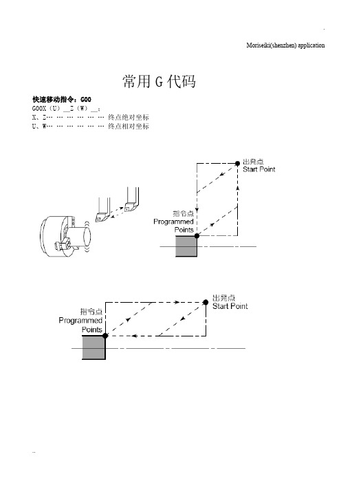
Moriseiki(shenzhen) application常用G代码快速移动指令:G00G00X(U)_Z(W)_;X、Z………………终点绝对坐标U、W………………终点相对坐标直线切削指令:G01G01X(U)_Y(V)_Z(W)_F_;X、Y、Z………………终点的绝对坐标U、V、W………………终点的相对坐标F………………进给速度每转进给G99:F0.2……0.2mm/rev每分进给G98:F200……200mm/min圆弧切削:G02、G03G02(G03)X(U)_Z(W)_R_F_;G02(G03)X(U)_Z(W)_I_K_F_;G02……………顺时针方向圆弧G03……………逆时针方向圆弧X、Z……………终点的绝对坐标U、W……………终点的相对坐标R………………圆弧半径(圆弧角在180°以上时,不能指令R)I……………从起点到圆心的X轴方向的距离和方向(半径值)K……………从起点到圆心的Z轴方向的距离和方向F………………进给速度每转进给G99:F0.2……0.2mm/rev每分进给G98:F200……200mm/min螺旋插补指令:G02、G03XY平面内的螺旋插补:G17G02(G03)X(U)_Y(V)_Z(W)_I_J_F_;G17G02(G03)X(U)_Y(V)_Z(W)_R_F_;YZ平面内的螺旋插补:G19G02(G03)Y(V)_Z(W)_X(U)_J_K_F_;G19G02(G03)Y(V)_Z(W)_X(U)_R_F_;G17、G18……………螺旋插补平面选择X、Y、Z ……………螺旋插补终点坐标I、J、K ……………从螺旋插补起点到中心的距离和方向R ……………螺旋插补半径F ……………进给速度(沿圆弧的进给速度)2~3、7~8的螺旋角和大圆的螺旋角要相同。
θ……………螺旋角L……………导程D……………螺纹直径主轴最高转速设定指令:G50G50S_Q_;S……………主轴最高回转速度Q……………主轴最低回转速度切削速度一定指令:G96G96S_M03(M04);G96S_M203(M204);S_……………切削速度M03(M04)…………主轴或第1主轴正转(主轴或第1主轴反转)M203(M204)………第2主轴正转(第2主轴反转)回转速度一定指令:G97G97S_M03(M04);G97S_M203(M204);S_……………主轴回转速度M03(M04)……主轴或第1主轴正转(主轴或第1主轴反转)M203(M204)……第2主轴正转(第2主轴反转)主轴回转速度、切削速度关系:主轴回转速度、工具进给速度关系:(参数设定)暂停指令:G04G04X_;G04U_;G04P_;X1.0(U1.0)(P1.0)=1sX1(U1)(P1)=0.001s主轴一回转所需时间:每分进给指令:G98G98…… F_;单位:直线轴:mm/min 回转轴:°/min每转进给指令:G99G99…… F_;单位:mm/min螺纹G32、螺纹切削循环G92标准格式:(参数1265.1=0)直螺纹G32 Z(W)_F(E)_Q_;G92 X(U)_Z(W)_F(E)_;锥螺纹G32 X(U)_Z(W)_F(E)_Q_;G92 X(U)_Z(W)_R_F(E)_;蜗旋G32 X(U)_F(E)_Q_;特殊格式:(参数1265.1=1)1 直螺纹G32 Z(W)_F(E)_Q_;G92 X(U)_Z(W)_F(E)_;锥螺纹G32 X(U)_Z(W)_F(E)_Q_;G92 X(U)_Z(W)_I_F(E)_;蜗旋G32 X(U)_F(E)_Q_;﹡X………(G32)螺纹终点X坐标………(G92)第一回切入的直径﹡Z…… …螺纹终点Z坐标﹡U、W …(G32)螺纹切入始点到终点的距离和方向…………(G92)同上﹡R、I……锥度的X方向距离(带符号的半径值)﹡F、E……螺纹导程,E精密导程切削﹡Q ……… 多头螺纹切入点间的角度,省略为零(范围:0.001~360.000)攻丝G32格式:G32 Z(W)_F_;﹡Z ……攻丝加工终点z坐标﹡W……攻丝开始点到结束点的距离和方向﹡F ……螺距(mm)用G32攻丝时,参数#1270.6=1。
森精机

M00
程序停止
M01
选择性停止
M02
程序结束
M03
主轴正转 (CW)
M04
主轴反转 (CCW)
M05
主轴停止
M06
自动换刀
M07
喷雾冷却开
M08
喷油冷却开
M09
冷却关
M10
锁紧分度头
选配功能
M11
松开分度头
选配功能
M19
主轴定位开
M20
自动断电开
M29
刚性攻牙
M30
程序结束并重置
M31
取消轴互锁
刀具位置补正2倍缩 短
刀长长补正取消
G48H_ G549
取消比例
G50
比例
G51X_Y_Z_P_
取消可编程镜向
G50.1IP_
G51.1
可编程镜向
G51.1IP_
G52
局部坐标系选择
G52IP_
G53
机械坐标系选择
G53IP_
G54~G59
工作坐标系选择
G90G54
G54.1
追加工作坐标系选择
G54.1P_
G10.6 IP_ G11 G12.1
G13.1 G15 G16 G17 G18
取消极坐标插补
G13.1
取消极坐标命令
G15
极坐标命令 G16
指定XY工作平面 指定XZ工作平面
G17G02X_Y_Z_R_或 者 G17G02X_Y_Z_I_J_K _
G18G02X_Y_Z_R_或 者 G18G02X_Y_Z_I_J_K _
• R.勿将任何工具或量具随意置放于机器的移动部位 或控制面板上。
CINCINNATI机床零点设置

CINCINNATI机床零点设置当X/Y/Z/U轴丢失零点以后机床会出现“300:X/Y/Z/U AXIS NEED ZERO”报警,或者观察参数1815.4变成为0,可以确定机床零点丢失。
导致机床零点丢失的原因有:(1)机床伺服电池电量低于5V(2)SDU模块损坏,但会同时出现FSSB报警。
(3)光栅尺损坏在确认伺服电池电压不低于5V,并且机床没有电池报警的前提下,需要对机床进行零点的重新设置。
机床的X轴零点在最左侧接近软极限,Y轴在靠近操作门处接近负极限,Z轴零点在最上端接近正极限。
为了消除报警先将各个轴的零点设置在一个大概的位置即将1815.4由0改为1。
1:X轴零点的设置。
因为X轴的零点不涉及换刀的问题,所以X轴零点的位置可以不是很精确。
查看参数1320和1321。
把X轴开到机床的一个极限位置(接近硬极限),比如正极限。
此时机床的机械坐标是500,而1320里面的数值是1000,那么我们就将X轴向负方向摇1000,走到-500坐标值。
此时将1815.4由0改成1,关机重启。
X轴零点设置完成。
2:U轴零点设置U轴一共36把刀,先把36号刀旋转到当前换刀位置。
如果此时M/C界面下的“TOOL DRUM POSITION”是10号刀,而当前位置是36号,需要进行如下操作才能将当前刀位与“TOOL DRUM POSITION”显示的刀位号相同。
(1)写保护改成1(2)操作面板上程序保护打到0(3)长按“ALTER CAL”键3秒,在M/C界面右上角会闪烁一行字“SET ENABLE”(4)在M/C界面下按“SET”软键。
(5)“TOOL DRUM POSITION”显示“00”刀位设置成功。
此时如果刀位和刀具位置还有偏差,可以在“JOG”模式下按下操作面板上的“CHAIN INC”或者是“CHAIN DEC”手动旋转U轴直到U轴位置与刀具位置相吻合,最后再修改1815.4由1-0-1. U轴零点设置成功。
大森3i系统原点位置设定方法
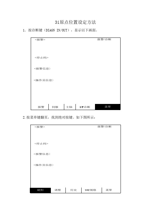
3i原点位置设定方法1.按诊断键(DIAGN IN/OUT),显示以下画面。
2.按菜单键翻页,找到绝对按键。
如下图所示:
3.按绝对键,如下图所示:
扩展建,即菜单右边的按钮。
画面显示如下:
4.按INPUT 输入,系统提示初期设定,在()分别在输入(0)(1)(1),如下图所示
5.按INPUT输入键。
将机床移动到X250,Z500的位置。
在()分别在输入(2)(250)(500),如下图所示
6.设定,在()里分别输入(1)(1)(1),如下图所示:
设定完成,系统断电,机床断电。
过一会,机床上电,系统上电。
系统正常
注: 1.更换驱动器电池时,机床断电,装上电池即可。
2. 初期设定时,急停开关是打开的。
如有问题请及时联系我们,谢谢
大森数控技术发展中心有限公司 2009-5-13
(注:专业文档是经验性极强的领域,无法思考和涵盖全面,素材和资料部分来自网络,供参考。
可复制、编制,期待你的好评与关注)。
DAEN3i-L系统原点设定方法
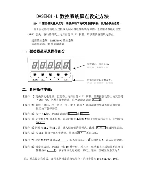
DASEN3i-L数控系统原点设定方法注:BS驱动器设置原点时,系统必须下电或是急停状态,否则会发生危险。
由于驱动器电池电压过低或是编码器电缆断裂等原因,造成驱动器绝对位置(ABS)丢失,驱动器每次上电后出现AL 32 报警,所以需要重新设定原点。
适用数控系统:DASEN3i-L数控系统
适用驱动器:BS系列驱动器
一、驱动器显示及操作部分
二、具体操作步骤:
【操作 1】更换新的电池后,驱动器上电后出现AL32报警,需要按驱动器上的复位键“SW3”键,把所有报警清除,直至驱动器显示
【操作 2】系统上电后,松开急停开关,把X
轴和Z轴移动到想要设为原点的位置。
然后按下急停开关。
【操作 3
【操作 4】先按住SEL键不松开,再同时按住▲键和▼键(按住5秒左右),直到显示
【操作 5】同时按SEL和SET键,进入现在值清除模式,此时成闪烁显示。
【操作 6】按SET 键执行现在值清除,结束闪烁。
【操作 7】双击MODE即当前值值为0,表示设定完成。
【操作 8】设定完成后,驱动器下电10秒钟后,再上电。
驱动器上电后如果不出现报警且表示原点设定完成。
系统上电后,机械坐标系变为0。
注:原点设定完成后,必须重新设定系统软限位(系统参数为600,601,604,605)。
用操作键进行参数设置,
监测,伺服调整,报警复
参数显示,状态显示,
调整值,报警等显示。
东京精密三次元使用技术手册
¾系统的组成一、各部件的名称:三次元坐标测量机二、XYZ2000操作软件介绍*快捷方式**进入联机**选择GEM *测量数据的表示方法:1,直角坐标的表示方法。
测定点用X、Y、Z、坐标表示。
2,圆柱坐标的表示方法。
测定点用AXY(角度)、Z表示,根据平面不同而变化。
三、一般的测量顺序1)系统的启动(P1)。
•自动校正手顺¾补助处理→自动校正(元 FAMILY TREE导轨面导轨面、开机手顺:4.1 打开UPS(图1)的电源开关,然后打开冷却空气机(图2)。
P 图6U图10、关机手顺:5.1先退出操作画面(图图15PC主机开关控制开关拧到OFF三个月Y轴内的气动轴的走行面(光尺的上面和侧面)的污物。
目视1)取下Y轴的外壳用有机溶剂(无水酒精等)擦拭干净。
2)少量的灰尘用柔软的抹布擦拭。
3)光尺上的脏物要小心除去。
六个各轴(X、Y、Z、)光尺上的脏污。
目视1)各轴光尺侧的外壳取下(方法见附页)。
2)用脱脂棉沾少量的丙酮或酒精,轻轻的擦拭。
在擦拭的过程必须小心慎重,防止擦伤。
三次元日常保养要领7、一般测量手顺4) 校正测头 测头NO:在校正球上测量5点以上后按终止键(第一坐标系设定完毕)5)基准面设定A面上测量3点以上后按终止6) 原点设定B孔中测量3点以上后按终止7) 基准轴设定C孔中测量3点以上后按终止﹏以上5)7)步骤操作完后第二坐标系设定完毕8) 测量D孔测量3点以上后按终止「X=50 Y=30」9) 系统的终止(P4参照)ENTE功能菜单机能处理7—2 电子显微镜和ITV照相机系统的测量使用方法1) 系统的启动(P1参照)2) 把校正球和测量物固定在平台上。
3) 选择测量再开始。
(A49)4) 几何形状自动判别(AI机能)OFF5)测量平面的固定ENTE6)测头直径的变更测头直径:07)原点设定“十”线在A孔的四周测量3点以上后按终止8)基准轴设定“十”线在B孔的四周测量3点以上后按终止以上7﹏)8)步骤操作完后第二坐标系设定完毕9)测量“十”线在C孔的四周测量3点以上后按终止“十”线在D边上测量1点后按终止10)系统的终止(P4参照)8·机能处理机能处理测量功能处理是在测量处理执行过程中和自动测量处理执行过程中插入执行处理处理和内容如下处理代码F0手动方式测量的场合。
森精机 NH4000操作手册

操作手册适用机型NH4000DCGA 章节操作面板1 供电电源开关2 操作面板3 NC操作4 功能选择键A-1 供电电源开关A-1-1 主电源开关A-1-2 NC电源接通/切断开关 [ON/OFF]A-1-3 急停开关 [EMERGENCY STOP]A-1-4 RS232C 端口A-1-5 存储卡端口A-2 操作面板 [OPERATION PANEL]备注:A-2-1 面板钥匙开关 [PANEL]A-2-2 模式选择开关 [MODE]A-2-3 自动操作开关 [CYCLE]功能说明:START: 此开关用于存储器,MDI模式以及带模式下启动自动操作, 在自动操作过程中该开关上方的指示灯亮.STOP: 此开关用于自动操作中轴的停止, 当轴运动停止开关上方的指示灯亮当执行试切或程序检查时,要时刻准备按下该按钮. 以防发生危险。
要重先启动自动操作时,再次按下START 按钮。
A-2-4 功能开关 [FUNCTION]A-2-4-1 单段执行功能 [SBK]该功能通常用在检测程序正确与否, 在自动执行程序的情况下一段一段地执行程序进行试切削。
所谓程序段是指以EOB代码(;)结束的一行程序。
注:A-2-4-2 选择停止按钮 [OSP]当该功能有效时,程序中执行到M01指令时程序会暂停,此时主轴停转,冷却液供给停止,各轴不移动。
A-2-4-3 反斜杠不执行按键 [BDT]按下该按键,指示灯亮,表明该功能有效,当执行到前面加有反斜杠的一单段程序时,就会跳过该段而直接执行到下一句A-2-4-4 空运行功能 [DRN]该功能忽略程序中指明的切削速度,所有轴的运动按照由进给速度修调开关来控制,该功能用于缩短程序检查时间。
A-2-5 状态指示灯 [STATUS]A-2-6 刀具夹紧和松开功能 [TOOL CLAMP/TOOL UNCLAMP]A-2-7A-2-8 进给速度修调开关 [OVERRIDE]A-2-9 快速移动速度修调开关 [RAPID OVERRIDE]注意点:对于手动操作,即使将快速移动设置到100%,实际进给也固定在50%上。
新代绝对式原点设定步骤
新代绝对式原点设定步骤1. 概述嘿,朋友们!今天我们要聊的可不是天上掉下来的馅饼,而是关于“新代绝对式原点”的设定步骤。
听起来可能有点复杂,但其实没那么难!就像煮泡面,只要掌握了关键步骤,分分钟就能上手。
那我们就来看看这套流程,保证让你明白得像喝水一样简单!2. 第一步:了解原点的重要性在开始之前,咱们先来聊聊为什么这个“原点”这么重要。
想象一下,原点就像你生活中的GPS,没有它,你可能会在街头转圈圈,找不到家。
原点设定得当,才能确保后续操作的精准性,才能让你在数据的海洋中畅游自如。
毕竟,谁也不想在工作中碰到“失联”的感觉,对吧?有了原点,所有的数据都能如同流水线般,顺畅得很。
2.1 理解绝对式原点说到绝对式原点,大家可能会想:“这又是什么高大上的名词?”其实,简单说就是一种固定的、可靠的位置。
比如说,你家楼下的便利店,永远都在那里,不会因为某个节日就搬家。
绝对式原点就是这样,提供一个不变的参考点,让你在数据处理中可以放心大胆地运作。
2.2 设定原点的必要性好啦,听完这段,你应该明白设定原点的重要性了吧。
没有这个“锚点”,你就像是无头苍蝇,东奔西跑,最后还不知道自己在干啥。
所以,设定这个原点,首先要把自己对这个流程的理解升华一下,做到心中有数。
3. 第二步:具体设定步骤接下来,我们进入最重要的环节,设定步骤。
这个过程就像做菜,一步一个脚印,别着急,慢慢来。
3.1 收集数据第一步,得收集你需要的数据。
这就像你准备去参加一场美食节,得先知道有哪些摊位、卖什么。
数据收集可以从多个渠道入手,比如之前的记录、现场调查、网络搜索等等。
说白了,就是得把所有的材料准备齐全,心里有个谱儿。
3.2 确定参考点接着,找一个合适的参考点。
这一步可关键了,就像你在海边搭帐篷,得选一个平坦的地方,避免风吹日晒。
选好之后,记得把这个点标记清楚,确保后续操作时不至于迷路。
3.3 设定原点然后,终于轮到你设定原点了!这时候,咱们可以使用一些工具,比如软件界面上的标记功能,或者直接在数据表里加个注释。
机台原点设置的部分流程
机台原点设置的部分流程
机台原点设置相关流程
1.检测原点传感器开关是否正常工作,可以通过手持
查看,或者用万用表测试电压。
2.判断原点开关,常开常闭方式,设置好。
3.移动机台,判断机台运动方向是否正常。
4.检查机台螺距和行程设置是否正常。
以上都设置正常,就可以按回原点测试。
具体设置步奏如下:
1.轴到达原点传感器位置时,通过查看手持输入端信号(1、2、3)显示1,移动轴后显示变为0。
或使用万用表测量原点信号线与地之间的电压,轴到达原点传感器位置时,原点信号为高电平;轴不在原点传感器位置时,原点信号为低电平。
2.当轴到达原点传感器位置时,手持显示的输入端信号(1、2、3)显示1,则原点信号设置为常开。
3.通过手持操作轴运动,确保轴运动方向与手持操作方向一致。
4.具体参数设置如下:
X--每转脉冲数6400,螺距52mm,行程250mm,原点偏移0mm;Y--每转脉冲数6400,螺距52mm,行程250mm,原点偏移0mm;Z--每转脉冲数6400,螺距52mm,行程100mm,原点偏移0mm;。
森精机NMV5000操作手册
关于本手册 About this Manual
• 请将此手册置于显著标记位置,以便需要时备查。
• 若对本手册有任何疑问,请致电森精机服务部。
• 若本手册遗失或损坏,请致电森精机服务部或经销商。
• 若因机床改进而造成本手册内容变更,恕不另行通知。
• 保留所有权利:在没有获得森精机的书面同意之前,不允许 对本操作手册进行任何形式的复制。
操作手册 OPERATION MANUAL
适用机型 Applicable Model
NMV1500 DCG NMV3000 DCG NMV5000 DCG NMV8000 DCG/40
NMV8000 DCG/50
适用数控装置 Applicable NC Unit
MSX-701IV
MSX-711IV
在开始操作、维护或编程之前,请仔细阅读森精机、数控装置制造商及设备制 造商提供的手册,从而充分理解手册中包含的信息。 请妥善保存这些手册,切勿遗失。 Before starting operation, maintenance, or programming, carefully read the manuals supplied by Mori Seiki, the NC unit manufacturer, and equipment manufacturers so that you fully understand the information they contain. Keep the manuals carefully so that they will not be lost.
• All rights reserved: reproduction of this instruction manual in any form, in whole or in part, is not permitted without the written consent of Mori Seiki.
新代原点设置步骤
新代原点设置步骤
嘿,朋友们!今天咱就来讲讲新代原点设置步骤,这可真是个有趣又重要的事儿呢!
你想想看,就好比你要去一个陌生的地方,得先找到那个起始点吧,新代原点设置不就跟这差不多嘛!
咱先得把准备工作做好呀,就像要出门得先穿好鞋子一样。
把设备啥的都检查检查,看看有没有啥小毛病,可别到时候关键时刻掉链子哟!然后呢,找到那个设置的入口,就跟找家门钥匙孔似的,得找对地方才行。
接着呀,按照提示一步一步来。
可别小瞧了这些步骤,就跟搭积木似的,一块一块得放对地方,不然整个就垮啦!有时候可能会遇到一些小麻烦,比如说某个选项不太明白啥意思,别着急,就好比走路遇到个小水坑,咱跨过去不就完事儿啦!
你说这设置新代原点是不是挺有意思的?就像给自己的小天地划个范围一样。
要是弄错了,那可就像在迷宫里走错路啦,得绕好大一圈才能回来呢!
咱得细心点,别马马虎虎的。
这可关系到后面的一系列操作呢,要是一开始就歪了,那后面不就全歪啦?这可不是开玩笑的哟!
有时候可能会觉得有点繁琐,哎呀,怎么这么多步骤呀!但你想想呀,等设置好了,那用起来多顺手呀,就像给自己量身打造的一样。
设置好了之后,可别就不管啦,得时不时检查检查,就跟给车做保养似的,确保一切都正常运行。
不然哪天突然出问题了,那不就傻眼啦!
反正呀,新代原点设置步骤虽然不算特别难,但也得用心去对待。
就像对待一个宝贝似的,好好呵护它,让它为我们好好服务呀!大家可别不当回事儿哟,这可是很重要的呢!。
数控机床原点及参考点设置及实例
数控机床原点及参考点设置及实例
数控机床原点及参考点设置及实例
数控机床原点及参考点设置及实例
1、机床原点的设置
机床原点是指在机床上设置的一个固定点,即机床坐标系的原点。
它在机床装配、调
试时就已确定下来,是数控机床进行加工运动的基准参考点。
(1)数控车床的原点
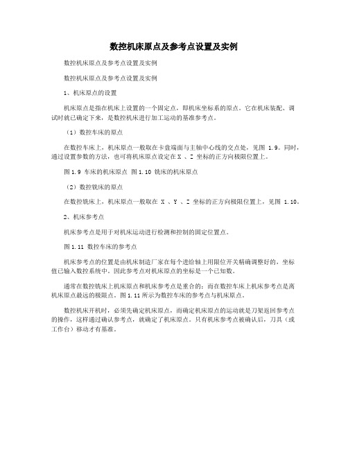
在数控车床上,机床原点一般取在卡盘端面与主轴中心线的交点处,见图 1.9。
同时,通过设置参数的方法,也可将机床原点设定在X 、Z 坐标的正方向极限位置上。
图1.9 车床的机床原点图1.10 铣床的机床原点
(2)数控铣床的原点
在数控铣床上,机床原点一般取在X 、Y 、Z 坐标的正方向极限位置上,见图 1.10。
2、机床参考点
机床参考点是用于对机床运动进行检测和控制的固定位置点。
图1.11 数控车床的参考点
机床参考点的位置是由机床制造厂家在每个进给轴上用限位开关精确调整好的,坐标
值已输入数控系统中。
因此参考点对机床原点的坐标是一个已知数。
通常在数控铣床上机床原点和机床参考点是重合的;而在数控车床上机床参考点是离
机床原点最远的极限点。
图1.11所示为数控车床的参考点与机床原点。
数控机床开机时,必须先确定机床原点,而确定机床原点的运动就是刀架返回参考点
的操作,这样通过确认参考点,就确定了机床原点。
只有机床参考点被确认后,刀具(或
工作台)移动才有基准。
日本森精机NL2000原点设置
Establishment and Adjustment of the zero return position for Z-axis using following procedure.Determinant of Z-axis zero return position based on Spindle Large Nose. For checking distance from Spindle Large Nose to zero return position, need to remove the chuck from the machine.So this manual considers zero point reference indexes (zero point index marks) is Z-axis zero (Refer to << REFERENCE >> on last pages about exact distance from SpindleThe function key menu is changed as indicated below. Press the [ F6 ] “ OPE PANEL ” function key to display the OPERATION PANEL screen.Move the cursor to the “ ZERO POINT ADJUSTMENT ” using [ ↑ ] [ ↓ ] cursorWhen the cursor is aligned with “ ZERO POINT ADJUSTMENT ”, press the [ → ](“ VALID ” is highlighted)OPERATION PANELSet the Z-axis “ RELATIVE COORDINATE ” value to “ 0.000 ” at the Z-axis machine zero point in according to the following steps 2.3.1 ~ 2.3.3.Press the [ POS ] (Position) function key to display the CURRENT POSITION Press the [ F2 ] “ REL. ” (Relative) function key on CURRENT POSITION screen] (relative coordinate of Z-axis) using data input keys and press the [ F10 ] “ ORIGIN ” function key on “ RELATIVE COORDINATE ” screen.The W-axis coordinate value (Z-axis relative coordinate value) is set to “ 0.000 ”.RELATIVE COORDINATEWhen the “ D ” is on the buffer area on the screen, press the [ F3 ] “ NC SYSTEM ”Press the [ F5 ] “ MENU ” function key to change the function key menu as indicated below.When the function key menu is changed, press the [ F1 ] “ ABS-SRV ” (Absolute Servo Monitor) function key to display the ABS SERVO MONITOR screen.ALARM/DIAGN 1Perform Z-axis initial setting in according to the following steps 4.1 ~ 4.2.) ” and [ 1 ] in the Z-axis (< Z >) setting value parenthesis ( )After step 4.1, “ INITIAL SET (ABS.) ” is displayed and the “ STATE ” display on the ABS. POSITION SET screen changes to “ ORIGIN SET ”.After step 5.1, the “ STATE ” display on the ABS. POSITION SET screen changes toEstablish the Z-axis zero return position in according to the following steps 6.1 ~ 6.3. Move the Z-axis in the “ - ” direction (to the spindle direction) using manual pulseWhen performing the above step 6.1, axis travel is stopped automatically at the next If axis travel exceeds 30 mm the operating procedure has been performedWhen axis travel is stopped, the “ STATE ” display on the ABS. POSITION SET screen changes to “ OK ” and established Z-axis zero return position.Performing steps 4 ~ 6 completes establishment of the Z-axis zero return position.Move the cursor to the “ ZERO POSITION SET ” using [ ↑ ] [ ↓ ] cursor movement(“ VALID ” is highlighted)] data input key and [ INPUT ] button on “ INCREMENTAL ” screen.The “ Z ” (incremental coordinate value) is set to “ 0.000 ”.Display the ABS. POSITION SET (Absolute Position Set) screen using following steps.Press the [ SYSTEM ] function key to display the S/W MODULE TREE screen.Press the [ NC DGN ] soft key on S/W MODULE TREE screen.[ S/W MODULE TREE ]Press the [ ABS-SRV ] (Absolute Servo Monitor) soft key to display the ABS SERVO MONITOR screen.[ SERVO MONITOR ]] (advance) page selection key once on ABS SERVO MONITOR screen.。
数控机床原点的设定
数控机床原点的设定机床原点的设定KND系统:将机床停到原点位置,在驱动器上按住“TU2”,直到变成“数值‘新代系统SYNTEC :将机床停到原点位置,在”回零“模式下,”串列参数“---”绝对设定“---设定原点---确定发那科系统FANUC:参数#1815 B5=1,断电重启,参数#1815B4=1断电重启。
三菱系统MITSUBISHI:”维护’里,先输密码---“绝对位置”将0=1和#1=1,后用手轮将对应轴向向负向移动,直到状态出显示“结束”,断电重启。
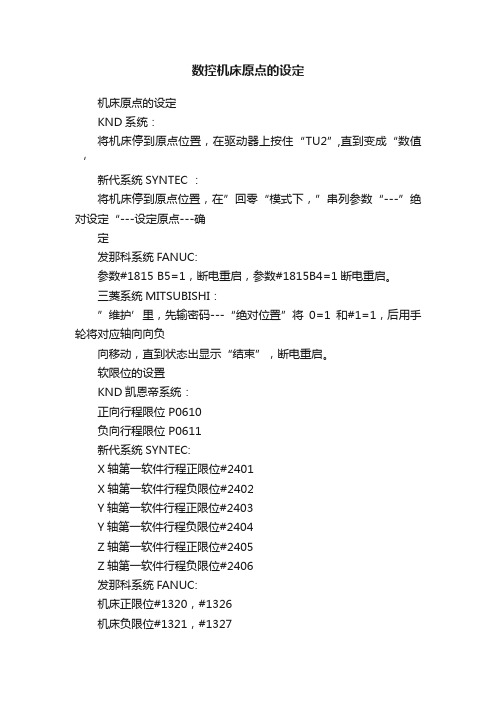
软限位的设置KND凯恩帝系统:正向行程限位 P0610负向行程限位 P0611新代系统SYNTEC:X轴第一软件行程正限位#2401X轴第一软件行程负限位#2402Y轴第一软件行程正限位#2403Y轴第一软件行程负限位#2404Z轴第一软件行程正限位#2405Z轴第一软件行程负限位#2406发那科系统FANUC:机床正限位#1320,#1326机床负限位#1321,#1327三菱系统MITSUBISHI:机床正限位#2013,机床负限位#2014FANUC数控机床机械原点的设置在通常情况下,设置数控机床机械原点的方法主要有以下两种:1)手动使X、Y、Z三轴超程印利用三轴的极限位置选择机械原点。
2)利用各坐标轴的伺服检溯反馈系统提供相应基准脉冲来选择机床参考点即机械原点。
由于第一种方法是机床厂家通常建议的也是较为简便和实用的方法.因此本文在此详细介绍第1种做法。
以X轴为例,设置步骤如下:(1)将机床操作面板上的方式选择开关设定为MDI方式。
(2)按下机床MDI面板上的功能键[OFS/SET]数次,进入设定画面。
(3)将写参数中的0改为1,由此,系统进入了参数可写状态。
此时机床出现。
SWO 100参数写入开关处于打开”的报警信息。
忽略这条报警信息,设置完参数后改回为0即可。
(4)按下功能键lsYSTEM】,进入系统参数键面。
通过参数搜索找到参数1815(如表l所示)通常情况下,X 轴的#4APZ或#5 APC会显示为0,若不为0就将其设定为0。
- 1、下载文档前请自行甄别文档内容的完整性,平台不提供额外的编辑、内容补充、找答案等附加服务。
- 2、"仅部分预览"的文档,不可在线预览部分如存在完整性等问题,可反馈申请退款(可完整预览的文档不适用该条件!)。
- 3、如文档侵犯您的权益,请联系客服反馈,我们会尽快为您处理(人工客服工作时间:9:00-18:30)。
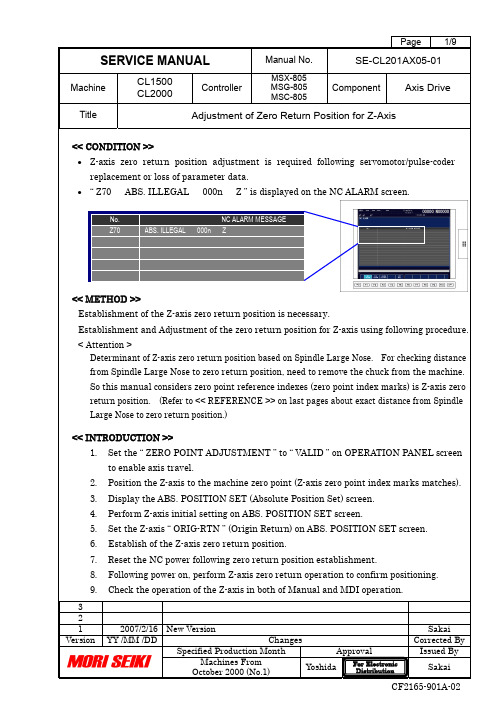
Establishment and Adjustment of the zero return position for Z-axis using following procedure.
Determinant of Z-axis zero return position based on Spindle Large Nose. For checking distance from Spindle Large Nose to zero return position, need to remove the chuck from the machine.
So this manual considers zero point reference indexes (zero point index marks) is Z-axis zero (Refer to << REFERENCE >> on last pages about exact distance from Spindle
The function key menu is changed as indicated below. Press the [ F6 ] “ OPE PANEL ” function key to display the OPERATION PANEL screen.
Move the cursor to the “ ZERO POINT ADJUSTMENT ” using [ ↑ ] [ ↓ ] cursor
When the cursor is aligned with “ ZERO POINT ADJUSTMENT ”, press the [ → ]
(“ VALID ” is highlighted)
OPERATION PANEL
Set the Z-axis “ RELATIVE COORDINATE ” value to “ 0.000 ” at the Z-axis machine zero point in according to the following steps 2.3.1 ~ 2.3.3.
Press the [ POS ] (Position) function key to display the CURRENT POSITION Press the [ F2 ] “ REL. ” (Relative) function key on CURRENT POSITION screen
] (relative coordinate of Z-axis) using data input keys and press the [ F10 ] “ ORIGIN ” function key on “ RELATIVE COORDINATE ” screen.
The W-axis coordinate value (Z-axis relative coordinate value) is set to “ 0.000 ”.
RELATIVE COORDINATE
When the “ D ” is on the buffer area on the screen, press the [ F3 ] “ NC SYSTEM ”
Press the [ F5 ] “ MENU ” function key to change the function key menu as indicated below.
When the function key menu is changed, press the [ F1 ] “ ABS-SRV ” (Absolute Servo Monitor) function key to display the ABS SERVO MONITOR screen.
ALARM/DIAGN 1
Perform Z-axis initial setting in according to the following steps 4.1 ~ 4.2.
) ” and [ 1 ] in the Z-axis (< Z >) setting value parenthesis ( )
After step 4.1, “ INITIAL SET (ABS.) ” is displayed and the “ STATE ” display on the ABS. POSITION SET screen changes to “ ORIGIN SET ”.
After step 5.1, the “ STATE ” display on the ABS. POSITION SET screen changes to
Establish the Z-axis zero return position in according to the following steps 6.1 ~ 6.3. Move the Z-axis in the “ - ” direction (to the spindle direction) using manual pulse
When performing the above step 6.1, axis travel is stopped automatically at the next If axis travel exceeds 30 mm the operating procedure has been performed
When axis travel is stopped, the “ STATE ” display on the ABS. POSITION SET screen changes to “ OK ” and established Z-axis zero return position.
Performing steps 4 ~ 6 completes establishment of the Z-axis zero return position.
Move the cursor to the “ ZERO POSITION SET ” using [ ↑ ] [ ↓ ] cursor movement
(“ VALID ” is highlighted)
] data input key and [ INPUT ] button on “ INCREMENTAL ” screen.
The “ Z ” (incremental coordinate value) is set to “ 0.000 ”.
Display the ABS. POSITION SET (Absolute Position Set) screen using following steps.
Press the [ SYSTEM ] function key to display the S/W MODULE TREE screen.
Press the [ NC DGN ] soft key on S/W MODULE TREE screen.
[ S/W MODULE TREE ]
Press the [ ABS-SRV ] (Absolute Servo Monitor) soft key to display the ABS SERVO MONITOR screen.
[ SERVO MONITOR ]
] (advance) page selection key once on ABS SERVO MONITOR screen.。
