基于计算机视觉的障碍物检测与测量(IJISA-V2-N2-3)
基于机器视觉的轨道障碍物检测算法研究

基于机器视觉的轨道障碍物检测算法研究随着自动驾驶技术的发展,轨道障碍物检测算法的研究变得越来越重要。
这个算法的目标是通过分析车辆周围的图像信息,检测和识别出存在于轨道上的障碍物,以防止与其相撞或造成事故。
1.图像预处理:首先,需要对输入的图像进行预处理以减少噪声和提高图像质量。
一些常用的预处理技术包括图像平滑、灰度化、边缘检测和图像增强等。
2. 目标检测和跟踪:在预处理完成后,需要对图像中的障碍物进行检测和跟踪。
目标检测算法可以通过使用一些特征描述子(如Haar特征、HOG特征、深度学习特征等)来提取图像中的目标,然后使用分类器对目标进行分类。
目标跟踪算法可以使用一些滤波器(如卡尔曼滤波器)来估计目标的位置和速度,并跟踪目标的运动轨迹。
3.障碍物识别和分类:在检测到目标后,需要对目标进行识别和分类,以确定目标的类型和属性。
这可以通过比较目标的特征向量与事先训练好的模型进行匹配来实现。
例如,可以使用支持向量机、随机森林等分类器来对目标进行分类。
4.预测和决策:在识别和分类目标后,需要根据目标的位置、速度等信息进行预测和决策。
预测算法可以根据目标的运动状态估计目标未来的位置和姿态,以便及时采取相应的措施。
决策算法可以根据目标的危险程度和交通规则等因素,做出避让或停车等相关决策。
以上是基于机器视觉的轨道障碍物检测算法研究的一些重点内容。
当然,这个研究领域还有很多其他的挑战和问题,例如不同天气条件下的检测效果、复杂场景下的目标检测和跟踪等。
未来,随着深度学习等技术的发展,基于机器视觉的轨道障碍物检测算法将会得到更进一步的提升和应用。
基于双目视觉的道路障碍物识别与检测方法研究
基于双目视觉的道路障碍物识别与检测方法研究李靖;李杜;胡文花;李文进【摘要】随着城市化的迅猛发展和轿车的推广,交通安全问题与日俱增.道路障碍物的识别与检测成为国内外的研究热点.文章主要研究车辆在行驶过程中双目视觉传感器获取的图像,从图像中获得障碍物信息,起到预警的效果.【期刊名称】《江苏科技信息》【年(卷),期】2017(000)011【总页数】4页(P52-55)【关键词】双目视觉;障碍物检测;图像处理【作者】李靖;李杜;胡文花;李文进【作者单位】湖南水利水电职业技术学院,湖南长沙 430131;湖南水利水电职业技术学院,湖南长沙 430131;湖南水利水电职业技术学院,湖南长沙 430131;湖南水利水电职业技术学院,湖南长沙 430131【正文语种】中文根据交通部门的统计,中国交通事故的致死率平均为27.3%,位于31个国家中的第3位。
出现交通事故的主要原因无非就是疲劳驾驶、酒后驾驶、超速行驶、占道行驶等。
而交通事故的主要表现就是碰撞,其中大部分是车与车碰撞以及车与人碰撞。
根据Daimler-Chrysler公司研究表明,如果驾驶员在事故发生时能够有额外0.5秒的时间提醒自己,这样将会减少60%交通事故的发生,如果将额外警告的间延长至1秒钟,则会减少90%的交通事故。
因此构建一个新型的障碍物检测与识别系统,可为智能驾驶提供诸多便利。
图像识别技术作为图像处理研究领域的重要分支之一,是基于数据处理等理论,利用计算机分析提取原始图像中的前景信息,模仿人的视觉系统感知外部世界各种形状的一项技术。
图像识别技术的应用前景极为宽广,本文主要结合智能驾驶来研究双目识别技术。
将使用结构规范化的普通公路,建立基于双目的计算机视觉系统,实现车辆在行驶过程中对障碍物的检测识别,以及对道路线的检测识别,确定车辆与道路的相对位置以及车辆与障碍物的相对位置和相对速度。
为智能驾驶的辅助系统提供实时的外界环境信息。
双目视觉系统由图像获取、摄像机标定、特征提取、立体匹配、三维深度确定、内插共六步来实现。
基于立体图像的实时障碍物检测方法(IJIEEB-V6-N1-5)
I.J. Information Engineering and Electronic Business, 2014, 1, 42-48Published Online February 2014 in MECS (/)DOI: 10.5815/ijieeb.2014.01.05Real-Time Obstacle Detection Approach usingStereoscopic ImagesNadia BahaComputer Science Department, University of Science and Technology Houari Boumediene, Algiers, Algerianbahatouzene@usthb.dzAbstract —In this paper, we propose a new and simple approach to obstacle and free space detection in an indoor and outdoor environment in real-time using stereo vision as sensor. The real-time obstacle detection algorithm uses two dimensional disparity map to detect obstacles in the scene without constructing the ground plane. The proposed approach combines an accumulating and thresholding techniques to detect and cluster obstacle pixels into objects using a dense disparity map. The results from both analysis modules are combined to provide information of the free space. Experimental results are presented to show the effectiveness of the proposed method in real-time.Index Terms —Obstacle detection, real-time, stereovision, disparity map.1.IntroductionObstacle detection is one of the fundamental problems of mobile robotics. In order to navigate in the world, it is necessary to detect those portions of the world that are dangerous or impossible to traverse. Popular sensors for range-based obstacle detection systems include ultrasonic sensors, laser rangefinders, radar, stereo vision, optical flow, and depth from focus. Because these sensors measure the distances from obstacles to the robot, they are inherently suited for the tasks of obstacle detection and obstacle avoidance. However, none of these sensors is perfect. Popular active sensors used for obstacle detection include laser, radar, lidar and ultrasonic sensors. The main advantage of active sensors is their ability to measure distance and speed of the target object in bad weather and poor lighting conditions. The major disadvantages of these sensors are interference with the environment, difficult interpretation of output signals, high power consumption, high acquisition price, poor resolution and incapability to detect small obstacles [1]. Moreover, stereo vision and optical flow are computationally expensive. Indeed, a motion based method uses the assumption that each moving object can be considered obstacle for this we need to compute a flow optic. The mainly problem of this method is located in computing and interpreting a flow optic in real times. Stereo vision systems have advantages of low cost, low power consumption, no interference with environment and a high degree of mechanical reliability. But the relatively slow processing speed of existing stereo vision methods limit their applications in real world problems, mainly due to the long computing time required for establishing stereo correspondences. However, visual navigation takes much attention after web cameras were introduced a few years ago since its cost is attractive comparing with previous sensors. Recent progress of processing techniques such as GPU and FPGA enables stereo reconstruction to run in real-time.Stereo vision exploits the fact that a single point in a scene appears in slightly different locations in neighbouring views of the scene. If the views are from two suitably aligned and calibrated cameras, with parallel lines of sight, a feature in the left image is horizontally shifted relative to the feature in the right image. This image shift, called the disparity, is directly related to the distance from the camera to the point in the scene: distant points have small disparity, while nearby points have large disparity. A disparity map consists of all the possible disparity values in an image. This is an image of the same size as the stereo pair images containing the disparity for each pixel as an intensity value. Such a map is basically a representation of the depth of the perceived sceneIn this paper, we propose a novel visual obstacle detection method which combines an accumulating and thresholding techniques to detect and cluster obstacle pixels into objects using a disparity map. The advantage of this approach is that it is very fast and permits us to detect a large number of obstacles of varied shapes and sizes.This paper begins with an overview of the obstacle detection algorithms in the literature. Section 2 presents the proposed method: obstacles and free space detection from a dense disparity map. Experimental results are shown in section 3. Finally, we make concluding remarks.2.Previous workThe perception of free space and obstacles in a scene is essential for safe driving. Among various sensors for scene perception, a stereo-vision is promising as it provides 3D perception data.Numerous vision based works have tried to detect a specific object that is important in a traffic scene. The object includes pedestrian [2], vehicle [3], bicycle [4] and so on [5].Obstacle detection through image processing has followed two main trends: single-camera based detectionand two (or more) camera based detection (stereovision based detection). The monocular approach uses techniques such as object model fitting [6], appearance-based obstacle detection [1, 7, 8, 9] etc. The estimation of 3D characteristics is done after the detection stage, and it is usually performed through a combination of knowledge about the objects (color, texture) [10, 11] and the camera parameters.The stereovision based approaches have focused on the binary classification problem of ground/obstacle separation. The methods are mainly categorized into three types: disparity map based, image remapping and 3D analysis method.First, the disparity map based methods [12,13,14,15,16,17,18,19,20,21] detect obstacles on the basis of disparity calculations. They have the advantage of directly measuring the 3D coordinates of an image. The main constraints concerning stereovision applications are to minimize the calibration and stereo-matching errors in order to increase the measurement accuracy and to reduce the complexity (computationally expensive) of stereo correlation process. Second, the image remapping method utilizes an image transformation for ground/obstacle separation [22, 23, 24]. One common technique is called the IPM (Inverse Perspective Mapping) [24]. The IPM is a transformation between the ground plane and the image plane. By the IPM two virtual ground images are generated from original stereo images. With the flat ground plane assumption, any difference in the two ground images represents non-ground objects, i.e. obstacles. A similar principle is also applied to the work in [25], that a stereo matching with the original and the ground-compliant matching windows is used instead of the image transformation. The methods mentioned above do not need the full 3D reconstruction. However they have several limitations. Real urban areas often do not have lane marking, and roads are occluded by crowded traffic. The IPM method is sensitive to the error of the camera geometry with respect to the ground plane. In order to overcome the limitations mentioned above, some works have analyzed a 3D model of an environment. In [26], obstacles are detected by checking connectivity of points in the reconstructed point cloud. To reduce computational load and complexity of 3D analysis, the use of simplified models such as an elevation map [27, 28, 29] is popular.Many obstacle detection methods have been proposed based on two approaches above, but the processing time and accuracy of the existing methods is not appropriate for real-time systems. Therefore, a new approach for obstacle detection based on disparity map is proposed in this paper. Our proposed method is faster and more accurate than existing methods for obstacle detection. 3.Proposed approachThis vision system has the task of detecting obstacles and recognizing safe navigable areas in an images pair. Using stereo reconstruction, a disparity image can be converted into set of 3-D points. The problem is now to identify the points among this set that belong to obstacle surfaces. For this, we propose a visual obstacle detection method which combines an accumulating and thresholding techniques to detect and cluster obstacle pixels into objects using a disparity map. The method for detecting obstacle points is presented in this section.3.1 Obstacle detection method3.1.1 HypothesisWe assume that the ground is flat and appears on the disparity map as a contiguous zone of rows having the same disparity value. An object located on the floor (vehicle, pedestrian, tree) is characterized by a portion of vertical or quasi vertical plane in the scene. The objective is to find such plans from a stereoscopic view.3.1.2 The MethodIn this paper we propose a method for the detection of free space and generic obstacles in an indoor and outdoor environment, focusing on the analysis of the dense disparity map image. The idea of this approach is first to build the so-called new disparity map obtained by accumulating disparities along the lines of the disparity map image. This provides a side view of the scene being studied. Secondly this new-disparity map image is analyzed in order to extract the longitudinal profile of the scene in order to detect the ground and therefore to detect obstacles.In the first time, for each row i of the disparity map image (LxC), the pixels which have the same disparity (d) are accumulated. See fig. 1.Then for each value of d, if the cumulative number corresponding to d is greater than some threshold S, the pixels which have a disparity equal to d in the row i are set to zero in the disparity image. Thus we obtain a map where dominant disparity is replaced by the value 0 which corresponds to the ground disparity.In this way, we distinguish the pixels belonging to the ground plane characterized by the disparity value equal to 0 and those belonging to obstacles. Then the pixels belonging to obstacles are grouped according to criteria of connectivity in order to detect and separate allobstacles in the image disparity. Fig. 2 illustrates the obstacle detection process.The value of the threshold S is important. Indeed, we remark, when we take a small value for the threshold S, we extract all the pixels belonging to the ground plane, but we obtain a less accuracy obstacle map. However, when we take a large value of the threshold S, we obtain more accuracy in the obstacle map, but it does not remove all the pixels belonging to the ground. So it is important to take a good value for this parameter for a good detection. Fig.3 shows the impact of the threshold value on the obstacle detection method.a bc dFigure. 3: a : original image, b : Disparity map, c : obstacle detection with small value of S, d : obstacle detection with a great value of SThe next algorithm shows a linear-time implementation of our obstacle detection method.3.2 Free Space ComputationThe obstacle detection algorithm described in the previous section generates an obstacle map where each obstacle can be described by the highest point on the left corner and the lower point on the right corner. Hence, bounding boxes are constructed around each obstacle, and then we obtain a free space estimation map which can be used by an autonomous mobile robot to allow a safe navigation.4. Experimental resultsIn this section, we describe the experiments conducted to evaluate the performance of the proposed method. Our aim is to detect all obstacles in the scene and to obtain a fast runtime which is the requirement of any obstacles detection system of autonomous mobile robot navigation. To validate the proposed method described in the previous section, we tested it on several pairs of real images of different scenes collected from the websites [30, 31, 32, 33].Row i Row LligneFig. 4 shows the results obtained at each step of our obstacle detection approach. The first column shows the disparity maps corresponding to each image, second column shows the obstacle detection maps and the third column shows the free space maps obtained, where the obstacles are represented by black color and the free space is represented by the green color. Our method was tested on indoor and outdoor scenes.Image 1Image 2Image 3Image 4Image 5Image 6Image7Image8Image9Image 10Image 11Image 12Image 12Figure. 4: Detection results in indoor and out door environment. Firstcolumn: disparity image, second column: obstacle detection map ,third column: free space map.We note that in all images, the obstacles have beenwell detected, however when two obstacles are close,they are considered as one obstacle in the free space map.This is the case of the obstacles in image 1 and image 7in Fig.4, the two respectively three obstacles areconsidered as a single obstacle in the free space map. We note that in all images, the obstacles have been well detected, however when two obstacles are close, they are considered as one obstacle in the free space map. This is the case of the obstacles in image 1 and image 7 in Fig.4, the two respectively three obstacles are considered as a single obstacle in the free space map. Now we present a comparison between the proposed method and two methods described in the literature [16, 34].An obstacle detection algorithm is not suitable for autonomous vehicle guidance if its computational demands do not allow for a sufficiently fast processing rate. Therefore, we computed the time needed to process stereo images pair by our approach. The proposed method was implemented using the C++ language and the timing tests were performed on a Personal computer PC, Dual-core T4500, 2.3 GHZ. We compared the performance of the proposed method to those of the other methods on the eleven images. Table 1 and Fig.5 illustrate the computation times obtained by our method in millisecond and two others methods [16] and [34]. For the other methods, we showed the computation time obtained on PC, Dual-core T4500, 2.3 GHZ. The proposed method yields favorable performances on all images, as compared to the other methods. The obtained results by our method showed that we are successfully able to detect obstacle in real-time. The total algorithm runs in less than 0,073ms. The fact that many parts of the algorithm can be processed in parallel, the calculation time can be reduced significantly if the algorithm is implemented using a parallel processing technique such as a GPU or FPGA devices.5.ConclusionThis paper presented a new method for robust obstacle detection and free space map estimation using stereovision. The method makes use of thresholding and accumulating techniques to detect obstacles using a dense disparity map. The proposed method has been tested in various images, both in an indoor and outdoor environment. The processing times obtained for different images are less than 0,073 ms. In addition, the proposed method exhibited favorable performances as compared to two other methods. This makes our system suitable for real-time applications.Our system is expected to be used as a driving assistance system.In future work, we plan to introduce in our method an image enhancement step to filter the input image with a 5×5 Gaussian filter to reduce the noise level. This eliminates the small variations between the neighboring pixels.The performance might be improved, for example, by employing a parallel processing technique such as a GPU and FPGA devices.References[1]Mittal A., Sofat S. and Venkatesh M. A NovelColor Coherence Vector based Obstacle DetectionAlgorithm for Textured Environments. The 3rdInternational Conference on Machine VisionICMV2010, 2010.[2]Geronimo D., Lopez A. M., Sappa A.D., Graf T.,Survey of Pedestrian Detection for AdvancedDriver Assistance Systems, IEEE Transactions onPattern Analysis and Machine Intelligence, vol. 32, issue 7, 2010, 1239 - 1258.[3]Sun Z., Bebis G., Miller R., On-road vehicledetection: a review, IEEE Transactions on PatternAnalysis and Machine Intelligence, vol. 28, no. 5, May 2006, 694 - 711.[4]Cho H., Rybski P.E, ZhangW., Vision-basedbicycle detection and tracking using a deformablepart model and an EKF algorithm, 2010 13thInternational IEEE Conference on IntelligentTransportation Systems (ITSC), 2010, 1875 - 1880.[5]Kang J. ,Chung M.J Stereo-Vision Based FreeSpace and Obstacle Detection with Structural andTraversability analysis Using ProbabilisticVolume Polar Grid Map, IEEE 5th InternationalConference on Robotics, Automation andMechatronics (RAM) 2011.[6]Nedevschi S., Schmidt R., Graf T.and Danescu R.High Accuracy Stereo Vision System for FarDistance obstacle Detection. IEEE IntelligentVehicles Symposium, Parma, Italy, June 2004.[7]Chan Nguyen Viet, An efficient obstacle detectionalgorithm using color and texture. World Academyof Science and Technology, 2009.[8]Suard F. A Pedestrian detection using infraredimages ad histograms of orientedgradients.Proceedings of the IEEE IntelligentVehicles Symposium,Tokyo, Japan, june 2006. [9]Ulrich I. , Nourbakhsh I.Appearance-BasedObstacle Detection with Monocular Color Vision.Proc. of the AAAI National Conference onArtificial Intelligence, Austin, TX, July/August2000.[10]Chumerin N., Ground plane estimation based ondense stereo disparity, Int. Conf. on neuralnetworks and artificial intelligence,2008.[11]Nguyen Viet C.,An efficient obstacle detectionalgorithm using color and texture, WorldAcademy of Science and Technology, 2009. [12]Nguyen T. Real-time obstacle detection for anAutonomous wheelchair using stereoscopiccameras” In Proc. Of the 29th Annual Inter. Conf.of the IEEE EMBS, August 2007, 4775-4778. [13] Baha N., Larabi S. Obstacle Detection WithStereo Vision based on the homography.In proc.Acit 2013,2007, 65-71.[14]Aldavert D. Obstacle Detection and alignmentusing an stereo camera pair. Technical report,Artificial Intelligence research institute, Spain,2008.[15]Chumerin N. Ground plane estimation based ondense stereo disparity. Int. Conf. on neuralnetworks and artificial intelligence, 2008. [16]Labayrade R, Aubert D. In vehicle obstacledetection and characterization by stereovision. InIEEE Intelligent Vehicles Symposium,Versailles.2004.[17]Lorigo L.M, Brooks R.A. Grimson W.E.L,Visually guided obstacle avoidance inunstructured Environnement In IROS, 1997,373-379.[18]Burschka D., Hager G.Stage classification fromdense disparity maps in indoor environments. InProc of ICPR Quebec, August 2002.[19]Zang Z., Weiss R., Hansoon A.R.Obstacledetection based one qualitative and Quantitative3D reconstruction. IEEE Tran on pattern analysisand machine Intelligence, Janv 1997, 15-26. [20]Okada R.,.Onouchi K. Obstacle detection usingprojective invariant and vanishing lines. IEEEInt Conf on Computer Vision France Octobre2003.[21]Aldavert D. Obstacle Detection and alignmentusing an stereo camera pairs pair. Technicalreport, Artificial Intelligence research institute,Spain, 2008.[22]Kubota S., Nakano T., Okamoto Y. A GlobalOptimization Algorithm for Real-Time On-BoardStereo Obstacle Detection Systems. IEEEIntelligent Vehicles Symposium, 2007, 7 - 12. [23]Xu Y., Zhao M., Wang X., Zhang Y., Peng Z.,YuanY., Liu H. .A method of stereo obstacledetection based on image symmetrical move,2009 IEEE Intelligent Vehicles Symposium,2009, 36 - 41.[24]Yang M., Yu Q., Wang H. Zhang B..Vision-based real-time obstacle detection and trackingfor autonomous vehicle guidance. ProceedingsVol. 4666, Real-Time Imaging VI, February2002, 65-74.[25]Perrollaz M., Spalanzani A., and Aubert D.Aprobabilistic representation of the uncertainty ofstereo-vision and its application to obstacle,IEEE Intelligent Vehicles Symposium (IV), June2010, 313-318.[26]Manduchi R., A. Castano A., Talukder A. andMatthies L.Obstacle and terrain classification forautonomous off-road navigation, AutonomousRobots, 2005, vol. 18, no. 1, 81-102.[27]Vergauwen M., Pollefeys M., and Gool L. V.Astereo-vision system for support of planetarysurface exploration, Machine Vision andApplications, April 2003, vol. 14, no. 1. 5-14. [28]Kayama K., Yairi I.E., Igi S..Construction ofelevation map for usercarried outdoor mobilerobot using stereo vision, IEEE InternationalConference on Systems, Man and Cybernetics,2003, 4631 - 4636.[29]Oniga F., Nedevschi S..Processing Dense StereoData Using Elevation Maps: Road Surface,Traffic Isle, and Obstacle Detection,”IEEETransactions on Vehicular Technology, March2010, vol. 59, issue 3, 1172 - 1182.[30]/research/rainbow/projects/dcbgrid/datasets/[31]puterbase.de/forum/showthread.php?t=677436&page=3[32]/ru/stereo/depthmaps.php[33]/search?q=carte+de+profondeur&hl=en&prmd=imvns&source=lnms&tbm=isch&ei=CebQT5W0DpCM4gT7kezRDA&sa=X&oi=mode_link&ct=mode&cd=2&ved=0CEIQ_AUoAQ&biw=1280&bih=705.[34]Lefebvre S. Mise en correspondancestéréoscopique de fenetresmonodimenensionnelles par logique floue:application àla détection d'obstacles routiers.Thesis in INRETS-LEOST, France, July 2008.Authors’ ProfilesNadia Baha: Received the Ph.D. in Computer Science Department at USTHB University (Algiers) in 2012. She is currently Associate Professor at the Computer Science Department of the University of Sciences and Technologies, Algiers, Algeria. She is an author of numerous publications for conferences, proceedings, and journals. Her research interests include computer vision, Image and Texture Analysis, 3D Vision, Obstacles detection, mobile robot navigation and real-time application in computer vision.TABLE 1: Processing time obtained by different methodsFigure 5: Processing time obtained by different methodsHow to cite this paper: Nadia Baha,"Real-Time Obstacle Detection Approach using Stereoscopic Images", IJIEEB, vol.6, no.1, pp.42-48, 2014. DOI: 10.5815/ijieeb.2014.01.05。
基于立体视觉和光流的障碍物探测方法
( S c h o o l o f C o mp u t e r E n g i n e e r i n g ,U n i v e r s i t y o f S h a n g h  ̄f o r S c i e n c e a n d T e c h n o l o g y , S h a n g h a i 2 0 0 0 9 3 , C h i n a )
c o r r e l a t i o n a p p oa r c h e s t o o b t a i n d i s p a r i t y ma p,o p t i c l a f l o w hr t o u g h g r a d i e n t b a s e d o b t a i n o p t i c a l l f o w i f e l d .Wh i c h i s t h e i f r s t s t e p f o r f u s i o n s t e r e o v i s i o n a n d o p i t c a l l f o w.o b t a i n e x a c t p o s i t i o n a n d t r e n d o f
关键词:立体视觉 ; 障碍物探测; 边缘索引; 光流场
Ob s t a c l e d e t e c i t o n me t ho d b a s e d o n s t e r e o v i s i o n a n d o p t i c a l lo f w
安全驾驶辅助功能, 从而为常规车辆因为驾驶员 主 观因素造成的交通事故提供智能技术的保障。车辆 驾驶辅助系统 中, 车辆前方障碍物的检测是不可缺 少的一部分 , 而且实时性要求 比较高 。 基于计算机视觉的障碍物探测方法通常分为三
基于双目视觉的障碍物检测算法
基于双目视觉的障碍物检测算法障碍物检测是自动驾驶技术中非常重要的一项任务,通过检测道路上的障碍物可以帮助智能车辆做出相应的决策,以避免碰撞和保持行驶安全。
其中,双目视觉是一种常用的检测技术,它通过两个摄像头来模拟人类双眼的视觉系统,能够获取更多的深度信息和空间结构,提高障碍物检测的准确性。
本文将介绍基于双目视觉的障碍物检测算法,并对其进行详细的解析。
首先是立体匹配,即确定左右视图中对应像素点的关系。
在双目视觉中,一般会采用计算视差(disparity)来表示两个视图之间的距离。
视差计算可以通过计算两个视图之间的灰度或颜色差异来实现,常用的算法包括均值差分算法、全局最小割算法和基于图像金字塔的快速立体匹配算法等。
这些算法能够有效地对图像中的特征点进行匹配,从而得到视差图。
接下来是深度推断,即根据视差图计算物体到摄像头的距离。
在深度推断中,常采用三角测量方法,利用摄像头的基线长度和相机模型,通过视差和摄像头参数的转换关系来计算物体的深度。
还可以通过双目校正来进一步提高深度推断的精度,通过将左右视图中的像素点映射到同一平面上,消除立体几何带来的误差。
最后是障碍物检测,即根据深度信息和图像特征来识别和分割障碍物。
一般可以利用机器学习的方法,通过训练一些障碍物的特征模型,如形状、纹理、颜色等,来进行障碍物的分类和识别。
常用的方法包括支持向量机(SVM)、卷积神经网络(CNN)和随机森林等。
此外,还可以结合点云数据和激光雷达等其他传感器的信息,来进一步提高障碍物检测的准确性和稳定性。
基于双目视觉的障碍物检测算法在实际应用中具有以下优点:首先,双目视觉能够获取更多的深度信息,能够更准确地测量物体的距离和空间结构,从而更好地判断障碍物的位置和大小;其次,双目视觉具有较高的实时性,适用于实时检测和决策,并且对光照、阴影等环境变化较为鲁棒;最后,双目视觉相机成本相对较低,易于集成和部署,适用于不同车型和场景的障碍物检测。
基于双目立体视觉的障碍物检测方法
基于双目立体视觉的障碍物检测方法摘要:提出了一种基于双目视觉的V视差图障碍物检测算法。
根据生成的视差图进一步生成V-视差图,提取V-视差图中的直线信息,通过这些直线信息可以锁定障碍物存在的大致区域,进而检测障碍物。
该算法对于光照、阴影等干扰不敏感,可以检测具有面特征的障碍物,适用于复杂背景下的障碍物检测。
关键词:障碍物检测;双目视觉;立体视觉;V-视差0 引言目前基于计算机视觉的障碍物检测算法主要分为两个大方向:基于单目视觉的障碍物检测和基于双目立体视觉的障碍物检测。
由于基于立体视觉的检测方法无需先验知识,对阴影、光照、反光等天气变化造成的背景变化不敏感,能给出障碍物的距离信息,可靠性高,并且在多个目标发生部分遮挡时仍能正确区分各运动目标。
基于立体视觉的检测方法有很大的应用前景。
基于双目立体视觉的障碍物检测算法主要有如下几种:①逆透视投影法(IPM)检测障碍物。
在道路平面假设下,根据逆透视投影原理(IPM),通过计算两个俯视图的差分检测任何突起于路面的物体。
②Disparity Space Image法检测障碍物。
该算法假设车辆静止时的俯仰角(pitch)相对于水平面是零,而当车运动时,车会随着路面的起伏而震动,pitch角将不再是零了,这时所获图像,相对于车静止时的所获图像,会产生垂直方向上的差异。
文献[3]给出了一种用来获取不同时刻的pitch角的方法,并利用立体视觉区域相关法检测障碍物。
以上提到的方法对阴影、光照、反光等天气变化造成的背景变化很敏感;有些在分析中还要一些不切实际的假设,例如:假设路面保持水平、假设车型满足某种条件等。
本文引进了一种V-视差法检测障碍物。
首先,对采集到的图片通过图像分割的方法来构建视差图。
在视差图中,沿图像坐标系中的V坐标轴方向(纵坐标)由上至下逐行扫描,累加具有相同视差值的像素点的个数,由此建立了V方向上的视差图。
通常,在V视差图中代表障碍物的直线一般是竖直的,因此可以通过从V方向视差图中提取出一些直线信息将障碍物从背景中提取出来。
基于计算机视觉的异常行为检测与分析研究
基于计算机视觉的异常行为检测与分析研究计算机视觉技术在近年来得到了迅猛发展,广泛应用于各个领域中。
其中,基于计算机视觉的异常行为检测与分析是一个备受研究关注的热门课题。
本文将就这一课题展开深入探讨,介绍其背景、意义、方法和应用等方面的内容。
1. 背景和意义:异常行为检测与分析旨在通过计算机视觉技术,对于特定场景或者人群的行为进行自动化的检测与分析,以便及时发现并预警可能存在的异常行为。
这一技术在公共安全、交通管理、视频监控等领域具有广泛的应用价值。
在公共安全方面,异常行为检测与分析可以帮助发现并预警恐怖袭击、犯罪活动等异常行为,提高应急响应能力。
在交通管理方面,该技术可以检测并预警交通事故、交通违法等异常行为,提升交通安全水平。
在视频监控方面,异常行为检测与分析可以帮助发现并预警人群聚集、人员闯入等异常行为,提高监控效果。
2. 方法和技术:在进行异常行为检测与分析时,常用的方法和技术包括物体检测与跟踪、行为分析与建模、异常判定等。
下面将对这些方法和技术进行一一介绍。
物体检测与跟踪是异常行为检测与分析的基础工作。
其目标是对于视频中的关键物体进行准确的检测与跟踪。
常用的物体检测与跟踪算法包括基于特征提取的方法、基于深度学习的方法等。
行为分析与建模是异常行为检测与分析的核心环节。
其目标是根据物体的运动轨迹和细粒度的动作特征,对于特定行为进行建模和识别。
常用的行为分析与建模方法包括基于特征匹配的方法、基于机器学习的方法、基于深度学习的方法等。
异常判定是对于行为分析结果的进一步处理和判断。
其目标是通过设定一定的阈值或者概率模型,对于检测到的行为结果进行分类。
常用的异常判定方法包括基于阈值的方法、基于概率模型的方法等。
3. 应用场景:基于计算机视觉的异常行为检测与分析技术在多个领域有着广泛的应用。
下面将分别介绍其在公共安全、交通管理、视频监控等方面的具体应用。
在公共安全方面,异常行为检测与分析可以应用于机场、车站、商场等公共场所,通过对于人群行为的分析,快速发现异常行为,并及时报警。
机器人视觉导航中的障碍物检测与避障技术研究

机器人视觉导航中的障碍物检测与避障技术研究随着人工智能和机器人技术的发展,机器人在各个领域中扮演着越来越重要的角色。
在机器人的自主导航中,障碍物检测与避障技术是至关重要的环节。
本文将探讨机器人视觉导航中的障碍物检测与避障技术的研究进展。
一、障碍物检测技术障碍物检测是机器人实现自主导航的关键步骤之一。
在过去的几十年里,学术界和工业界已经提出了许多障碍物检测方法。
其中,基于视觉的障碍物检测技术是最为常用和有效的方法之一。
1. 目标检测算法目标检测算法是障碍物检测中的核心技术之一。
近年来,深度学习方法的发展使得目标检测算法取得了显著的突破。
基于深度学习的目标检测算法如YOLO、Faster R-CNN和SSD 等已经在机器人障碍物检测中取得了良好的效果。
这些算法可以快速准确地检测出图像中的障碍物,并生成对应的边界框或者像素级别的遮罩。
2. 点云处理除了图像,机器人还可以通过激光雷达等传感器获取环境的三维点云信息,从而进行更准确的障碍物检测。
点云处理技术可以将点云数据转化为有用的信息,例如地面分割、物体分割和物体识别等。
基于点云处理的障碍物检测方法在机器人导航中也取得了一定的成功。
3. 智能传感器随着传感器技术的发展,越来越多的智能传感器被应用于机器人的障碍物检测中。
例如,具有深度感知能力的相机、声纳和毫米波雷达等,可以提供更丰富的环境信息,从而改善障碍物的检测和识别能力。
二、避障技术在机器人导航中,障碍物检测仅仅是解决问题的一部分,机器人还需要相应的避障策略来实现安全、高效的导航。
1. 路径规划算法路径规划算法是机器人避障的关键技术之一。
传统的路径规划算法如A*、Dijkstra和RRT等已经被广泛应用于机器人导航领域。
近年来,基于深度学习的路径规划算法也取得了一定的研究进展。
这些算法可以通过学习大量样本来获取更高效准确的路径规划策略。
2. 避障决策一旦检测到障碍物,机器人需要进行相应的决策来规避障碍物。
基于双目立体视觉的障碍物检测方法
基于双目立体视觉的障碍物检测方法
预览说明:预览图片所展示的格式为文档的源格式展示,下载源文件没有水印,内容可编辑和复制
基于双目立体视觉的障碍物检测方法
摘要:提出了一种基于双目视觉的V视差图障碍物检测算法。
根据生成的视差图进一步生成V-视差图,提取V-视差图中的直线信息,通过这些直线信息可以锁定障碍物存在的大致区域,进而检测障碍物。
该算法对于光照、阴影等干扰不敏感,可以检测具有面特征的障碍物,适用于复杂背景下的障碍物检测。
关键词:障碍物检测;双目视觉;立体视觉;V-视差
0 引言
目前基于计算机视觉的障碍物检测算法主要分为两个大方向:基于单目视觉的障碍物检测和基于双目立体视觉的障碍物检测。
由于基于立体视觉的检测方法无需先验知识,对阴影、光照、反光等天气变化造成的背景变化不敏感,能给出障碍物的距离信息,可靠性高,并且在多个目
标发生部分遮挡时仍能正确区分各运动目标。
基于立体视觉的检测方法有很大的应用前景。
基于双目立体视觉的障碍物检测算法主要有如下几种:①逆透视投影法(IPM)检测障碍物。
在道路平面假设下,根据逆透视投影原理(IPM),通过计算两个俯视图的差分检测任何突起于路面的物体。
②Disparity Space Image法检测障碍物。
该算法假设车辆静止时的俯仰角(pitch)相对于水平面是零,而当车运动时,车会随着路面的起伏而震动,pitch角将不再是零了,这时所获图像,相对于车静止时。
基于深度学习的障碍物检测研究

基于深度学习的障碍物检测研究作者:张舜郝泳涛来源:《电脑知识与技术》2019年第34期摘要:避障导航是自动导引小车领域的重要课题,障碍物检测则是其中的重要环节。
随着计算机视觉的发展,基于深度学习的图像目标检测算法已日趋成熟,针对自动导引小车避障检测对精准性和实时性要求都较高的情况,本文搭建深度学习模型,使用端到端的物体目标检测网络,对室内环境下自动导引小车可能的工作场景进行训练,在速度较快的情况下得到了很高的精准度。
关键词:避障检测;深度学习;自动导引小车;图像檢测中图分类号:TP311 文献标识码:A文章编号:1009-3044(2019)34-0185-03无人智能车一直是科研领域的热门话题,不论在无人驾驶领域,还是在AGV小车领域,避障一直是一个关键的课题。
在无人驾驶的领域研究中,主要有雷达和摄像头两种传感器,雷达主要有超声波雷达和激光雷达。
雷达传感器只能判断障碍的存在,而不能判别障碍的种类,而且随着一系列深度学习检测算法的提出,基于计算机视觉的识别和检测的算法的视觉传感器已经逐渐能够代替雷达传感器,基本满足AGV小车避障检测的需求。
传统的机器学习检测方法由以下步骤组成:1)输入待检测图像,并进行相关的预处理;2)使用滑动窗口方法获取候选框;3)对每个候选框取特征信息;4)使用分类器进行判定。
这些滑动窗口和特征提取相结合的传统机器学习算法,在早期取得了比较好的效果,但是其过高的计算复杂度、较差的实时性都成为限制其发展的阻碍,并且传统机器学习算法在应对复杂情形下的表现差强人意。
但自从2012年开始,AlexNet[1]的出现打破了这一现状,标志基于深度学习的图像检测算法开始发展。
基于深度学习的图像物体检测算法目前有两条分支。
第一条分支的基本原理是先生成候选区,再对候选区提取特征。
自R_CNN[2]模型开始,这条分支在精准度上取得了十足的进展;2015年提出的fast R_CNN[3]贝1J结合了R-CNN和SPP-NETf空间金字塔池化层)[4]的优点;2015年提出的faster R-CNNc5]结合了RPN候选框提取,相比于fast R-CNN进一步提高了效率;2017年提出的FPN(Feature Pyramid Network)[6]则解决了高层中无法检测细小物体的问题;2017年提出的Mask R_CNN[7]则基于faster R-CNN新增了基于掩码层的分割分支。
基于机器视觉的轨道车辆侧向盲区障碍物识别
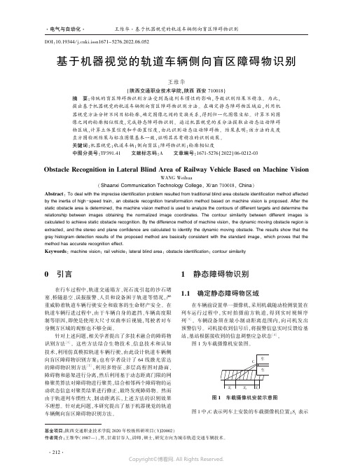
制等原因ꎬ即使是使用大尺寸双曲率后视镜ꎬ驾驶者对车
身侧方区域的观察也不够全面ꎮ
预警信号ꎮ 司机接收到信号后ꎬ将报警信息实时反馈给基
针对上述问题ꎬ相关学者提出了多技术融合的障碍物
识别方法
[1]
列 [3] ꎮ 车辆设备须在最小制动距离范围内ꎬ向司机发出
ꎮ 这些方法结合生物技术、信息技术和认知
技术ꎬ利用仿真模拟轨道车辆行驶ꎬ由此设计轨道车辆侧
λ i R′i = ( DW+Ln T ) R i
(1)
式中:D 表示车载摄像机与地面之间的距离ꎻn 表示地面
图像在摄像机坐标系中法向量ꎻW 表示旋转矩阵ꎻL 表示
平移向量ꎻλ i 表示变换尺度因子ꎬ该因子不是唯一的ꎬ而
是归一化结果 [9] ꎮ
步骤四:求取真实轮廓与预测轮廓间的相似性 [10] ꎮ
若相似性小于某一阈值ꎬ则对应的目标轮廓是障碍物
地面上的点对应于检测区域范围内点的运动方程ꎬ计算出相
小ꎬ则无需设置大搜索窗口ꎬ否则只能增加计算量ꎬ无法提高
应像素在 k+1 帧内的灰度值ꎮ 但由于障碍点不符合平面运
搜索速度ꎮ 在最后一帧中ꎬ估计当前区域的像素移至前一帧ꎬ
动方程ꎬ因此相应位置的像素灰度变化较大
然后扩大前一帧对应像素进行模式匹配ꎮ 按式(7)求出匹配
轮廓ꎬ否则不是 [11] ꎮ 两幅图像轮廓 G1 和 G2 相似性的计
(
1
w +
∑
NG
i∈G 1
k
i
2
θ i ∈障碍物 β i >阈值
θ i ∉障碍物 β i ≤阈值
(5)
2.2 计算立体置信度和平面置信度
空间可信度和平面可信度是图像块的基本属性ꎬ表示
其属于道路平面或三维目标的概率ꎮ
计算机视觉中的物体检测技术综述
计算机视觉中的物体检测技术综述随着互联网和科技的高速发展,计算机视觉技术逐渐得到了广泛应用。
计算机视觉技术通过利用计算机进行感知和理解,能够模拟出人类的视觉过程,并且在一定程度上达到了智能化的效果。
在计算机视觉技术中,物体检测技术作为重要的一项技术,一直是许多领域的关注焦点。
本文将为大家综述一下计算机视觉中的物体检测技术。
一、物体检测技术概述物体检测技术,顾名思义,即是通过计算机模拟出人类视觉过程中的“看见物体”的过程,并且能够标出图像中目标物体的位置坐标。
物体检测技术可以广泛应用于许多领域,例如安防监控、智能家居、自动驾驶、医学影像等。
通常情况下,物体检测技术被分为基于特征的检测和基于目标的检测两种不同的技术。
基于特征的检测方法,通常是指通过对图像进行一系列特定的运算,得到一些特殊的特征向量,再将这些特征向量与样本库中已知的图像特征进行对比,从而检测出目标物体。
而基于目标的检测,则是通过机器学习算法,学习并理解目标物体的形态、大小、颜色、纹理等特征,从而在新的场景下寻找到目标物体的位置。
二、基于特征的检测方法1. Haar特征检测Haar特征检测是一种基于特征的检测方法,该方法通过检测图像中不同层数的Haar特征完成目标检测任务。
Haar特征是指一个矩形区域内的像素值之和,通常情况下,这个矩形是以像素为单位的正方形,可以是灰度值、边缘、线段等。
Haar特征检测方法是目标检测中最经典的方法之一,然而这种方法也存在着一些问题。
例如,Haar特征在计算时需要对图像进行多重扫描,运算量较大,算法速度较慢。
并且该方法对于头部、脸部等曲线部位的对象检测效果不太好。
2. HOG特征检测HOG特征检测是一种基于特征的检测方法,其名字的全称是Histogram of Oriented Gradients(梯度方向直方图),简称HOG。
HOG特征检测方法通常被用于检测图像中的行人、车辆等对象。
HOG特征检测方法的实现过程比较简单,它将物体分成很多小的部分,并且计算每部分的梯度方向直方图。
- 1、下载文档前请自行甄别文档内容的完整性,平台不提供额外的编辑、内容补充、找答案等附加服务。
- 2、"仅部分预览"的文档,不可在线预览部分如存在完整性等问题,可反馈申请退款(可完整预览的文档不适用该条件!)。
- 3、如文档侵犯您的权益,请联系客服反馈,我们会尽快为您处理(人工客服工作时间:9:00-18:30)。
I.J. Intelligent Systems and Applications, 2010, 2, 17-24Published Online December 2010 in MECS (/)The Obstacle Detection and Measurement Basedon Machine VisionXitao Zheng1, Shiming Wang2, Yongwei Zhang11College of IT, Shanghai Ocean University, Shanghai 201306, China2College of Engineering Science and Technology, Shanghai Ocean University, Shanghai 201306, China xtzheng@, smwang@, zhangyongwei_108@Abstract - To develop a quick obstacle detection and measurement algorithm for the image-based autonomous vehicle (AV) or computer assisted driving system, this paper utilize the previous work of object detection to get the position of an obstacle and refocus windows on the selected target. Further calculation based on single camera will give the detailed measurement of the object, like the height, the distance to the vehicle, and possibly the width. It adopts a two camera system with different pitch angles, which can perform real-time monitoring for the front area of the vehicle with different coverage. This paper assumes that the vehicle will move at an even speed on a flat road, cameras will sample images at a given rate and the images will be analyzed simultaneously. Focus will be on the virtual window area of the image which is proved to be related to the distance to the object and speed of the vehicle. Counting of the blackened virtual sub-area can quickly find the existence of an obstacle and the obstacle area will be cut to get the interested parameter measurements for the object evaluation.Index Terms - obstacle detection; object measurement, ALV, virtual window.I.I NTRODUCTIONAutonomous land vehicles (ALVs) are useful for many automation applications that serve for both indoor and outdoor environments. Vision or digital image based obstacle detection for ALV navigation in outdoor road environments is a difficult and challenging task because of the great variety of object and road conditions, like irregular and unstable features on objects, moving objects, changes of illumination, and even rain. Successful ALV navigation requires the integration of the many techniques, like the environmental sensoring and learning, image processing and feature extraction, ALV location retrieving, travel path planning, vehicle wheel controlling, and so on.Vehicle intelligent drive system is also an important part of the intelligent transport system. Based on our driving experience, more than 90% of our information is from our vision and hearing, so using computer vision technique to solve this problem is a challenging work for every researcher in this field. The lane keeping and distance measurement based on the computer visionsystem.In reference [1], a real-time distance detection method is proposed to get the real-time distance between the camera car and the obstacle in the front. The paper uses the geometrical reasoning method to obtain the depth information. The shoot angle of the camera is the key factor that affects the accuracy of output. The work uses the two lane boundaries as a constraint to get the pitch angle. The problem is that the results are for static car tests, and algorithm needs to be combined with others to get all the required parameters.Reference [2] presents an obstacle detection method for AGV under indoor or outdoor environment. Corner or turn points are detected and tracked through an image sequencing camera and grouped into ground region using a method that is called co-planarity checking algorithm. The algorithm is initialized by 5-point planar projective and contour cue which is added to segment the ground region. The method can be applied to some ideal environment and the contour matching can be a problem in a lot of environments.Reference [3] is the previous work of this paper and it provides the quick detection of the existence of an obstacle, this is a key feature for ALV’s moving where safety is the highest requirement. The frames can be analyzed in a fragment of milliseconds and alert can be sent if an obstacle is found. But sometime the vehicle does not need to stop to wait for a clear road, it need to further analyze the situation and the surrounding environment to make decision whether to slow down or to stop, this part of job is not included in [3].Reference [4] proposes an effective approach to obstacle detection and avoidance for ALV navigation in outdoor road environments using computer vision and image sequence techniques. To judge whether an object newly appearing in the image is an obstacle or not, the object shape boundary is first extracted from the image. After the translation from the ALV location in the current cycle to that in the next cycle, the position of the object shape in the image is predicted, using coordinate transformation techniques based on the assumption that the height of the object is zero. The predicted object shape is then matched with the extracted shape of the object in the image of the next cycle to decide whether the object is an obstacle. A reasonable distance measure is used to compute the correlation measure between two shapes for shape matching. Finally, a safe navigation point is determined, and a turn angle is computed to18The Obstacle Detection and Measurement Based on Machine Visionguide the ALV toward the navigation point for obstacle avoidance. This is one camera based obstacle detection system and the moving speed is relatively slow, the work on the corner sensing can be applied in this paper.Reference [5] tries to establish restriction functions for lane lines tracks and reconstructs the lane line to get the necessary parameters. There is binocular camera to guide the vehicle moving and another camera on the roadside to trajectory comparison. Reference [6] proposesa function that can use a monocular camera to detect the lane edge and keep the vehicle in the lane. Reference [7] works on stereo color image with one camera and a lens. The job is based on the assumption that all the brake lights are working and can be clearly pictured. It is a good paper for car-following model which is sensitive to the emerging of the brake signal, i.e., when the traffic is slowing down. It will lose target if one brake light is out.There are a lot of papers that involve the lane detection and obstacle avoidance for ALV navigation in indoor or outdoor road environments using computer vision and image sequence techniques [4, 5, 8]. These methods need to search the whole pictured areas and feature matching can be unreliable.Reference [9] addresses the problem of visual object class recognition and localization in natural images. Field experiences show how histogram-based image descriptors can be combined with a boosting classifier to provide a state of the art object detector. Among the improvements the paper introduces a weak learner for multi-valued histogram features and shows how to overcome problems of limited training sets.Reference [10] summarizes the past work on object detection of feature extraction and classi1cation, proposes that feature selection is an important problem in object detection and demonstrates that genetic algorithms (GAs) provide a simple, general, and powerful framework for selecting good subsets of features, leading to improved detection rates.Reference [11] proposes an object detection approach using spatial histogram features. As spatial histograms consist of marginal distributions of an image over local patches, they can preserve texture and shape information of an object simultaneously. Their work employs Fisher criterion and mutual information to measure the discriminability and features correlation of spatial histogram features. They further train a hierarchical classifier by combining cascade histogram matching and support vector machine. The cascade histogram matching is trained via automatically selected discriminative features. A forward sequential selection method is presented to construct uncorrelated and discriminative feature sets for support vector machine classification.Reference [12] establishes a system that can detect moving object in the 3-D space and propose a background reduction method. The camera can be repositioned to track the moving of a target.As we know all these works are confined in a specific environment and the methods proposed above can be used in a certain circumstances.In this paper we will utilize a virtual area-based object detection rule to detect the height of an obstacle and the combination of the two camera images will be able to confirm the movement of the object over the picture; then use the location to retrieve the object area for further analysis. So the work is correlated to reference [3] and some problems of reference [3] are resolved. The system can be very efficient because the object area can be very small compared with the whole image and the image center is nearly found when the obstacle detection is done. The further analysis will tell the driver whether to wind around or to apply brake action..II.P ROPOSED O BJECT H EIGHT D ETECTION M ETHOD A.System ArchitectureFig 1 The structure diagram of target detectionThe system hardware architecture can be shown in Fig 1. The speed sensor is used to get the vehicle speed to do frame differentiation. The speed will be used to determine the height of the smaller object, like a cone or a deer. Lower camera can be viewed as collision prevention precaution and precise distance calculation camera; upper one can be used as lane detection, object pre-alerting, object height analysis, and observation camera.From Fig 2, we can see that each camera has different coverage and they will overlap in a considerable range. In Fig 3, we can see that the same virtual area will be in different position if we merge the two pictures. This will offer ID verification and approaching information of the object..Fig 2 The covering ranges of the two camerasFig 3 Overlapping of virtual area between two cameras B. Virtual Window(s)As we discussed above, the virtual windows are the only areas that we will be interested, which can be seen in Fig 9-11 as the gridded area. These windows can be dynamically added or deleted depending on the detected road condition. In this model, we will assign the area from 6-11 meters in front of the vehicle as the virtual grid, which is usually used for low-speed drive. Usually multiple windows should be assigned to lower window for smaller object detection and lane detection and larger object detection windows should be assigned to the upper camera. Grid shown in Fig 4 can be an example for slow country road driving window setting.Fig 4 Small object detection: multiple windowsVirtual windows can be placed at different positions toserve as the information window, attention window, and action window. Here for the obstacle height detection purpose, we will use the same number and size of windows for both cameras. The accurate mapping andquick resolution of the virtual windows on the picture reresolved by our previous work.Fig 5 The projected plane X-YFig 6 The original rectangle on the roadIn reference [1], the relationship between the actual road coordinate and the projected coordinate, which is the picture, can be shown in Fig 5 and 6, the conversion formula between the two coordinate can be seen in formula (1, 2). Detailed definitions of the subscripts can be found in [1].()()2212134122234111p p P P p p pP P pP k Y h k y k k y U G Y X U G k x k Y k y h h k Y k U G X x k k U G Y μ⎧+=⋅⋅⋅⎪−⋅⋅⎪⎪+=⎪⋅⋅⋅⎪⎨⁄⎪=⎪+⋅+⋅⎪⋅⎪=⎪⋅⋅+⎩()()()()()()()()()()102030400000002cos 2cos cos cos k tg H k tg k h k tg W h tg y tg y UG ⎧⎪=⁄α⎪⎪=γ⎪⎪=⁄γ⎨⎪=β⁄⎪⎪⋅−−αγ−α⎪=⎪γ−α−γ⎩0(2) Using formula (1) and (2), we can convert a pre-designated area in front of the car to a virtual area in the picture and vise versa.C. Object Height and Width AnalysisEach virtual window will be counted for the pixels occupied, if the occupied percentage is more than 50%, this window will be assigned black, otherwise white. The black and white windows will be compared against the other camera, the current frame situation will compared again with the following frame, the one with changing black spots will be the obstacle and the numbers of the windows will be the picture height, which can be converted to real height using formula (1) and (2). As seen in Fig 7, the object with a height FS is projected to the ground segment St, ST can be further projected to image size as shown in Fig 8. OE is the height of the camera.In order to implement our detection algorithm, we find that most road image areas have similar RBG values, so the pixels with this characteristics and the area with even color range are reset to white color. This road information needs to be inputted if different road base color is present. The painting and signs on the road will not affect road color selection. In our samples the asphalt road and stone road are tested and they are a good matchto the RGB rule.Fig 7 Projection of image length ST to obstacleheight FSFig 8 Image formation on camera1θFig 9 The view of the observer from different positions⎪⎪⎪⎩⎪⎪⎪⎨⎧⋅=⋅=+=⋅+=⋅−=Δ21120010102121tan tan θθθθctg S h ctg S h S S h S S h S S S I I I I (3)Applying Fig 7 to a moving condition, Fig 9 can be drew to show the height of an object in the observer’s eyes, i.e., the shadow length. In formula (3), ΔS is the distance moved in the given time interval, S 0 is the initial distance to the object, S 1 is the distance to the object at the next time interval, h 0 is the height of the cameras,θ1 and θ2 are the pitch angles at the two time intervals, h is the height of the object, S I1, S I2 are the viewed object lengths, need to be converted to the picture length using Fig 8, which is very typical for optical camera imaging system.When an obstacle is found and so an object is located, formula (3) can be used to retrieve the interested height data. There are five variables in formula (3), not include θ1 and θ2. Where ΔS is known if the speed and the time interval is known, and the height of the camera, which is h 0, is also known. So formula will be reduced to an equation of θ1 and θ2, which are unknown because of our moving positions. Note that we have two cameras that are positioned to the same level and symmetrically to the center line, so all the parameters in formula (3) are shared for two cameras, this triangle will give another equation for θ1 and θ2 to get their solution, therefore the solution of all the parameters. Note that we can only get pixels from the picture so the image height and width will be counted from black white small picture to get their pixels, whichcan be converted to actual shadow distances S I1, S I2 using Fig8. We have data redundancy so we can cross verify the effectiveness of image edge detection algorithms.III. E XPERIMENTThe experiment is done with a vehicle moving at 25km/h, the two cameras are horizontally positioned at the front of the vehicle and closely together, so in our model calculation the two cameras are considered at the same vertical location, the upper camera (which has a bigger pitch angle, or have a farther view, not actually higher in position) serves as the information and alert window and the lower one, which has a smaller view area but better focused, serves as the verification window. Both cameras are sampling at 10frame/s, calculation of 5 sample frames pictures are presented here from Fig 10 to Fig 19. Each frame is only processed against its sister frame and the following one or two frame. Calculations are focused on virtual windows and the half processed windows are shown in Fig 20-23, the grids are added to show the virtual window arrangement.As we already know, the virtual window will be positioned to interested area, where a possible object will appear. If the object is confirmed, which is done by the counting of blackened boxes (data shown in Tab 1) and compared with the previous frames, an object window will appear to cut the object off from the original picture and to do image processing, like the image format conversion and edge detection, pixel data can be found and compared with previous frame for stablenessevaluation. Tab 2 is the data for this experiment.Fig 10 Frame 1 image from camera 1Fig11 Frame 1 image from camera 2Fig 12 Frame 2 image from camera 1Fig13 Frame 2 image from camera 2Fig 14 Grid image of frame1 from camera 1Fig 15 Grid image of frame1 from camera 2Fig 16 Grid image of frame2 from camera 1Fig 17 Grid image of frame2 from camera 2Fig 18 Virtual windows isolated of frame1 (camera1)Fig 19 Virtual windows isolated of frame1 (camera2)It can be seen from Fig 10 to Fig 17 that the upper camera (camera 1) views farther and the lower one(camera 2) views closer. As the vehicle approaches the obstacles become bigger in the pictures. Figure 14 to Figure 17 are applied to intelligent grid. Fig 18 and Fig19 are the separated virtual windows.Fig 20 Processed windows isolated of frame1 (camera1)Fig 21 Processed windows isolated of frame3 (camera1)Fig 22 Processed windows isolated of frame3 (camera2) Fig 20 to Fig 22 are the processed virtual windows to count black boxes for obstacle detection. Fig 23-25 are the height and width analysis figure where the width and height of the object are measured.Fig 23 Middle object binary images of frame1 and frame2 (camera1)Fig 24 Difference image of middle object of frame1and frame2 (camera1)Fig 25 Middle object binary images of frame1 and frame2 (camera2)We can see the difference of the two objects in Fig 23-25, their height, width, the pixels occupied are all very different, this is another verification of the effectiveness of obstacle detection algorithm.So by counting the vertical continuous black spots, the difference prompts an obstacle, and by counting the pixels to the top and bottom of the object, we get the height of the object. If we apply the counting the left and right edge of the object window, we get the width. Applying formula (3), we have Tab 2. We will not elaborate the process to get the pixels length of height and width, because this is the known way to process the digital image.This quick estimation and multiple verification mechanism will avoid the miscalculation and ensure the driving safety.Tab 1 is the result of obstacle detection, where the black box numbers are presented for each frames and for each cameras. Tab 2 is the data from each object windows, and then converted by formula (3). The test run proves the two step method is effective. We can also see that the closer image intends to give bigger width which is still within our error tolerance level.The current method can not resolve the case when the object has similar color to the road. It also proved that when the weather condition is bad, like in the rain or in the night, the system will not be effective. This reason is that we do not apply a good background reduction algorithm, and the complicated illumination condition will considerably affect the detection and analysis. If possible, we will try to research these issues in our later project.Table 1 Camera 1 and Camera 2 frames900 pitch angle Fr1 Fr2 Fr3 Fr4 Fr5 camera height(m) 1.035 1.035 1.035 1.035 1.035 Black Boxes 2 4 4 5 777.80 pitch angle Fr1 Fr2 Fr3 Fr4 Fr5 camera height(m) 1.035 1.035 1.035 1.035 1.035 Black Boxes 2 4 4 5 8Table 2 Object Height and WidthFr1 pitch angle (87.40) Fr2 pitch angle(86.90) camera height(m) 1.035 1.035Obj dist(m) 11.83 9.75Obj Ht (pxl) 33 44Obj Ht(m) 0.48 0.50Obj Width(pxl) 8 11Obj Width(m) 0.12 0.13IV.C ONCLUSIONThis method presents a method to detector locate an obstacle, retireve the window that cover the obstacle and then use digital image processing technique to get the detailed measurement of the object. The measurement project the object to a shadow on the background andthen project the shadow to the those in the camera. This is an important effort to facilitate the ALV for its decision making process. Usually the two cameras have the same pitch angle and are symmetric to the center, which can not benefit from our obstacle detection with far view and close view. The structure and algorithm need to be improved in later work for easier projection calculation and enable full object detection, not just the two dimensions in this paper. Pattern recognition and neural network need to be introduced to help the learning process. But because of the hardware architecture relative feature of the system, the learning experience and knowledge base may not be able to be shared like these geometrical algorithms. Also, most of the current works are in the day light, the algorithm needs to be tested modified on different weather conditions to ensure the robustness for actual applications.R EFERENCES[1]Lei Guo, Youchun Xu, Keqiang Li, Xiaomin Lian.“Study on Real-time Distance Detection Based onMonocular Vision Technique”. Journal of Imageand Graphics. Vol 11, No.1, Jan, 2006.(inChinese)[2]Yong Zhou, Chao Chen, Qingtai Ye. “ObstacleDetection for AGVS Based on Computer Vision”.Machine Design and Research. Vol.21, No. 5, Oct,2005.(in Chinese)[3]Xitao Zheng, Yongwei Zhang. “An ObstacleDetection Method Based on Machine Vision”. TheChinese Symposium on Information Science andTechnology. 2010, page993-996.[4]Kuang-Hsiung Chen, Wen-Hsiang Tsai. “Visionbased obstacle detection and avoidance forautonomous land vehicle navigation in outdoorroads”. Automation in Construction, Volume 10,Issue 1, November 2000, Pages 1-25.[5]H.-H. Nagel, F. Heimes, K. Fleischer, M. Haag,H. Leuck, S. Noltemeier. “Quantitativecomparison between trajectory estimates obtainedfrom a binocular camera setup within a movingroad vehicle and from the outside by a stationarymonocular camera”. Image and Vision Computing,Volume 18, Issue 5, April 2000, Pages 435-444. [6]Xin Zhou, Xiyue Huang, Yu Li. “Lane Keepingand Distance Measurement Based on MonocularVision”. Journal of Image and Graphics. Vol.8(A), No.5. May, 2003. (in Chinese)[7]Joaquín Ferruz, Aníbal Ollero. “Integrated real-time vision system for vehicle control in non-structured environments”. EngineeringApplications of Artificial Intelligence, Volume 13,Issue 3, 1 June 2000, pages 215-236.[8]T Kato and Y Ninomiya. “An approach to vehiclerecognition using supervised learning”. Proc. ofMachine Vision Applications [C]. 1998, 77~80. [9]Ivan Laptev. “Improving object detection withboosted histograms”. Image and VisionComputing . 27 (2009), 535–544.[10]Zehang Sun, George Bebis, Ronald Miller.“Object detection using feature subset selection”.Pattern Recognition. 37 (2004), 2165 – 2176. [11]Hongming Zhang, Wen Gao, Xilin Chen, DebinZhao. “Object detection using spatial histogramfeatures”. Image and Vision Computing. 24 (2006)327–341.[12]Kun Zhu,Tangwen Yang,Qiuqi Ruan,Hongbo Wang,Jianda Han. “Real-Time Tracking and Measuring of Moving Objects Based OR Binocular Vision”. Robot. Vol, 31. No.4. July,2009. (in chinese)。