一个新的仿生吸附爬墙机器人
仿生壁虎爬墙机器人

仿生壁虎爬墙机器人1208104摘要:本文将从壁虎爬墙原理入手,介绍仿生壁虎爬墙机器人的运动原理和系统构成,并着重介绍爬墙机器人实现爬墙功能的关键技术,同时针对目前爬墙机器人存在的问题介绍爬墙机器人未来发展的方向。
关键词:壁虎;爬墙机器人;原理一、综述机器人是一门高度交叉的综合性学科,涉及到机械学、生物学、控制论与控制工程学、计算机科学与工程、信息科学、光学、电子工程学、传感技术、人工智能、人类学、社会学等诸多学科。
自从1959年美国制造世界上第一台工业机器人起,机器人的发展经历了示教(工业)机器人、感知(遥控)机器人、智能机器人三个阶段,仿生机器人也可以作为其中较为独特的一支。
仿生机器人以仿生学为核心的相关学科进行研究,运动仿生、感知仿生、控制仿生、能量仿生、材料仿生等诸多基础仿生技术的深入研究为仿生机器人的发展提供了一定的理论基础和技术支持。
根据仿生机器人的运动方式可以将机器人分为爬行机器人、飞行机器人、跳跃机器人以及水下机器人等,这些机器人在人类的生活、生产和军事中发挥了许多独特的作用。
因爬行机器人多在陆地上运动,方便控制,所以爬行机器人的研究最为广泛。
仿生爬行机器人根据仿生类型的不同,又可以具体分为爬壁机器人、仿蛇机器人、仿蜘蛛机器人、仿蚯蚓机器人、仿昆虫机器人等,本文介绍的仿壁虎爬行机器人即属于爬壁机器人的一种。
爬壁机器人的诞生是科学研究与实际生产的双重需要。
就科学研究而言,对爬壁机器人的研究可以有力的促进仿生机械学的发展。
对动物来说,运动是其捕食、逃逸、生殖、繁衍等行为的基础。
而对机器人来说,运动也是现代机器人实现各种功能的基础。
其中能够在光滑或粗糙的各种表面上自如运动的可控移动系统,即三维空间无障碍机器人(简称3DoF-3 dimensional-terrain obstacle free机器人即我们称作的爬壁机器人)是这类机器人的重要分支,其研究和研制水平已成为衡量一个国家科技水平的重要标志之一。
一种多足吸附式爬墙机器人
一种多足吸附式爬墙机器人发布时间:2022-10-24T06:20:45.267Z 来源:《中国科技信息》2022年第6月第12期作者:赵亮1 丁业升1 程飞扬1 朱翰宸1 郭超越 1 严依依1[导读] 为了实现搭载各种轻质量设备进行垂直墙面和水平墙面作业赵亮1 丁业升1 程飞扬1 朱翰宸1 郭超越 1 严依依11.湖北工业大学工程技术学院机械工程系湖北 430000摘要:为了实现搭载各种轻质量设备进行垂直墙面和水平墙面作业,设计一种以ESP32单片机为核心控制,使用真空吸附原理的多足爬墙机器人。
采用三维建模的方法进行机械结构的设计,通过样机实验的方法研究机构和控制系统存在的问题;提出了一套模仿生物形体结构与运动方式的仿生设计方法;设计实现了一套仿壁虎多足机器人原理样机,验证了在复杂环境下机器人实现稳定附着的有效性。
关键词:真空吸附;四足爬行;步态规划;安全性1 引言根据吸附原理及爬行原理不同,爬墙机器人可分为多足爬墙机器人、轮式爬墙机器人及履带式爬墙机器人。
其中多足爬墙机器人具有很强的环境适应性和运动灵活性,并且它可以通过足底的吸附装置爬行行走,具有很重要的研究意义和实用价值。
2 整体设计思路根据爬墙机器人结构原理,结合爬行类动物的吸附能力原理研究的基础上得出爬墙机器人的一些基本特点进行设计。
(1)应用三维实体设计软件进行三维模型搭建。
其次推导出多足机器人腿部运动学方程并进行相应运动学分析[1],规划多足机器人最佳步态顺序。
(2)解决多足机器人在壁面间过渡[2]的问题,借助图形学的思想对机器人的工作空间和壁面结构化的数学模型表达。
(3)分析机器人克服壁面障碍物的运动能力,以此建立分类准则对壁面障碍物进行分类,并结合障碍物权重用连续路径规划方法求解四足爬壁机器人壁面运动的引导路径。
3 吸附系统分析3.1 真空发生装置吸附系统采用的真空发生装置为直流无刷真空泵,它的尺寸小,重量轻,这样可以便于减轻机体重量。
一种新型仿生蜘蛛机器人行走机构的设计研究
一种新型仿生蜘蛛机器人行走机构的设计研究梁忠正;陈玉娟;沈家润;骆淳;陈宇航【摘要】本文运用真空吸附技术设计了一种能够运用6足稳定,实现行走、转弯、爬墙、避障的新型仿生蜘蛛机器人.【期刊名称】《现代制造技术与装备》【年(卷),期】2016(000)009【总页数】3页(P47-49)【关键词】蜘蛛机器人;真空吸附;行走机构;爬墙;避障【作者】梁忠正;陈玉娟;沈家润;骆淳;陈宇航【作者单位】上海师范大学信息与机电工程学院,上海 201418;上海师范大学信息与机电工程学院,上海 201418;上海师范大学信息与机电工程学院,上海 201418;上海师范大学信息与机电工程学院,上海 201418;上海师范大学信息与机电工程学院,上海 201418【正文语种】中文仿生蜘蛛机器人是对蜘蛛形状、运动原理和行为方式等进行模仿,相比履带式或轮式机器人,仿生蜘蛛机器人存在结构上的不足。
履带式机器人有更大的抓地面积,即使在一些坡度较陡的路面,履带式机器人也能顺利爬行,而蜘蛛机器人由于行走方式的不同,不能像履带式那样表现出色。
针对仿生蜘蛛机器人的这种缺点,采用不受地面材料限制的真空吸附法,给出了一种新型机器人的改进设计方案。
该设计方案在功能结构上既保留了蜘蛛仿生机器人环境适应能力强、运动灵活的特点,又克服了其攀爬陡坡时的缺点,且实验测试效果良好。
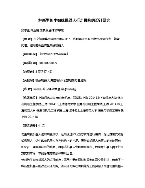
新型仿生蜘蛛机器人的结构设计如图1所示。
机器人本体是一个圆柱形结构,底盘为上下两层结构,电子硬件安装在下层底盘,感受器安装在上层底盘,机器人的核心部件都在两底板之间,保护效果很好。
躯干部分:考虑到机器人躯干部位对灵活度基本没有要求,无需搭建活动关节,且躯干不宜受到关节活动干扰,采用加工六边形铝合金作为底盘,既减轻了重量,又利于支撑及保护内部装置。
控制器采用arduino足,以满足机器人运算要求。
头部:在机器人上层底盘上安装采用激光扫描雷达作为主感受器,用于识别物体与避障,构成机器人的头部。
一种爬墙机器人[实用新型专利]
![一种爬墙机器人[实用新型专利]](https://img.taocdn.com/s3/m/9593aeeb03d8ce2f01662306.png)
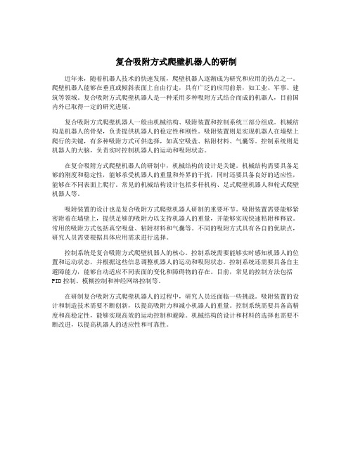
专利名称:一种爬墙机器人
专利类型:实用新型专利
发明人:梁健,叶国梁,欧阳天德,何锶汝,刘泽平,徐志翔申请号:CN201920311726.5
申请日:20190311
公开号:CN210000441U
公开日:
20200131
专利内容由知识产权出版社提供
摘要:本实用新型公开了一种爬墙机器人,利用机身上方的离心风机对空腔内进行抽吸,空腔内形成负压,令开有吸附空洞的底盘形成吸盘,使得机体可牢固地吸附着在各种形状的幕墙面上;且设有滑动机构,滑块可沿机身侧面的长度方向移动,使得两节机体之间的距离实现可调节,整个设备具有伸缩性,同时将滑块与设有转向电机的减速箱相连,再通过滑杆将两节机体进行连接,使得遇到曲面、拐角等时,利用转向电机翻转进而通过滑杆将前端机体抬起,可实现顺利翻越并通过障碍,具有灵活性,此实用新型用于机器人领域。
申请人:广东水利电力职业技术学院(广东省水利电力技工学校)
地址:510635 广东省广州市天河区天寿路122号
国籍:CN
代理机构:广州嘉权专利商标事务所有限公司
代理人:任毅
更多信息请下载全文后查看。
复合吸附方式爬壁机器人的研制
复合吸附方式爬壁机器人的研制近年来,随着机器人技术的快速发展,爬壁机器人逐渐成为研究和应用的热点之一。
爬壁机器人能够在垂直或倾斜表面上自由行走,具有广泛的应用前景,如工业、军事、建筑等领域。
复合吸附方式爬壁机器人是一种采用多种吸附方式结合而成的机器人,目前国内外已取得一定的研究进展。
复合吸附方式爬壁机器人一般由机械结构、吸附装置和控制系统三部分组成。
机械结构是机器人的骨架,负责提供机器人的稳定性和刚性。
吸附装置则是实现机器人在墙壁上爬行的关键,有多种吸附方式可供选择,如真空吸盘、粘附材料、气囊等。
控制系统则是机器人的大脑,负责实时控制机器人的运动和吸附状态。
在复合吸附方式爬壁机器人的研制中,机械结构的设计是关键。
机械结构需要具备足够的刚度和稳定性,能够承受机器人的重量和外界的干扰,同时还要具备良好的适应性,能够在不同表面上爬行。
常见的机械结构设计包括多杆机构、足式爬壁机器人和轮式爬壁机器人等。
吸附装置的设计也是复合吸附方式爬壁机器人研制的重要环节。
吸附装置需要能够紧密附着在墙壁上,提供足够的吸附力以支持机器人的重量,并能够实现快速粘附和释放。
常用的吸附方式包括真空吸盘、粘附材料和气囊等。
不同的吸附方式具有各自的优缺点,研究人员需要根据具体应用需求进行选择。
控制系统是复合吸附方式爬壁机器人的核心。
控制系统需要能够实时感知机器人的位置和运动状态,并根据这些信息调整机器人的运动和吸附状态。
控制系统还需要具备自主避障能力,能够自动适应不同表面的变化和障碍物的存在。
目前,常见的控制方法包括PID控制、模糊控制和神经网络控制等。
在研制复合吸附方式爬壁机器人的过程中,研究人员还面临一些挑战。
吸附装置的设计和制造技术需要不断创新,以提高吸附力和减小机器人的重量。
控制系统需要具备高精度和高稳定性,能够实现高效的运动控制和避障。
机械结构的设计和材料的选择也需要不断改进,以提高机器人的适应性和可靠性。
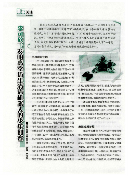
李可欣:发明高空仿生清洁机器人的少年创客
大的就 是 小 品 《大城 小爱 》,小 品演 绎 了农 一 针 一 线 亲 自缝 制 的 。如今 ,城 市 的女孩 子
民工 冒着生命 危 险 为高 楼幕 墙 做 清 洁 工作 有谁还 会 针线 活?李 可欣 克服 了各 种 困难 , 经 历的 奇 遇 。李 可欣 的 心 牵挂 着 那 些从 事 硬 生生地 把 自己变成 了女 红达 人。
恰巧 舍 友们 在宿 舍养 了一只名 为 “绿 豆 ”的 抱 着 电脑 画设 计 图 。一 旁的护 士姐 姐看 了设
小 乌龟 ,看到 舍 友 洗 “绿 豆 ”的情 景 ,她 突 计 作 品感 叹不 已 :“你 真是了不起 。”同时 ,
然 有 了灵 感 ,便 尝 试 仿 生乌 龟行 走 的设 计 护 士 姐 姐也 指 出 ,作 品 虽 好 ,但样 子 不 够 美
危 险 作 业 的农 民工 ,她 进 一 步 了解 到 目前
所 有 高 空意 外 坠 楼 事 故 中 ,大都 是 因为高 疯 狂 成 就 梦 想
空作业 防护 不 当导致 的。那 时。她 就萌 生了
她 的作 品体 积 不大 ,但 设 计 得 精 密 精
一 个 念 想 :设计 一款 自动 清 洁 机 器 人 来帮 致 。舵机 控 制板 排布 得 密 密麻麻 ,要 完成 这
灵 感 源 自生 活
201 8年 4月 21日,第 29届 江 苏 省青 少
年科 技创 新 大 赛 在 泰 州市 隆 重举 行 ,江 苏
省锡 山高 中李可 欣 的作 品吸引 了观 众和 评
委的眼球 。这款高空仿 生清洁机器人 ,精
致灵巧,操作 自如,可代替人工进行户外幕
墙 的清 洁工作 ,既 安全 便 捷 ,又 高效 。问辩
复合吸附方式爬壁机器人的研制

复合吸附方式爬壁机器人的研制随着科技的发展,机器人技术已经逐渐走入人们的日常生活中。
在各种机器人中,爬壁机器人因其独特的功能和应用场景而备受关注。
爬壁机器人可以在垂直表面上移动和工作,可以用于建筑外墙维护、安防巡逻、环境监测等领域。
目前市面上大部分的爬壁机器人都存在着运动控制精度不高、遇到特殊情况难以应对、吸附能力不足等问题。
研发一种具有复合吸附方式的爬壁机器人迫在眉睫。
爬壁机器人通常使用的吸附方式包括摩擦力、真空吸附、电磁吸附等。
单一吸附方式在应对复杂环境时存在着局限性。
为了克服这些问题,复合吸附方式应运而生。
复合吸附方式即利用多种吸附技术,根据具体情况灵活选择吸附方式,以克服其各自的缺陷,实现更高效、更稳定的爬壁运动。
这种技术将大大拓展爬壁机器人的应用范围和可靠性。
研制复合吸附方式爬壁机器人需要解决多个关键技术难题。
首先是吸附结构设计,需要设计一种能够根据不同表面特性灵活切换吸附方式的吸附结构。
其次是吸附控制技术,需要研究各种吸附方式的控制算法,并实现它们的智能切换和运动控制。
最后是多传感器融合技术,需要将视觉、力觉等多种传感器数据融合,实现对环境的精确感知和自适应运动。
在吸附结构设计方面,可以借鉴自然界的吸附原理,如蜥蜴的趾螯结构和极性分子吸附原理。
通过仿生设计,可以研制出具有多种吸附方式的结构,从而实现在不同表面上的高效吸附。
还可以利用材料学和纳米技术,设计出具有高强度、高韧性和多功能的吸附材料,提高爬壁机器人的吸附能力和稳定性。
在吸附控制技术方面,需要针对不同的吸附方式设计相应的控制算法。
对于摩擦力吸附,需要设计一种能够调节接触面积和摩擦系数的控制系统;对于真空吸附,需要设计一种能够调节气压和密封性能的控制系统;对于电磁吸附,需要设计一种能够调节电磁力大小和方向的控制系统。
还需要研究各种吸附方式的智能切换算法,实现在不同表面上的快速适应和稳定运动控制。
在多传感器融合技术方面,需要设计一种能够利用视觉、力觉等多种传感器数据,实现对环境的精确感知和自适应运动的算法。
复合吸附方式爬壁机器人的研制

复合吸附方式爬壁机器人的研制一、复合吸附方式爬壁机器人的概念和优势复合吸附方式爬壁机器人是一种利用多种吸附技术结合的爬壁机器人,其主要包括真空吸附、电磁吸附、压力吸附等吸附方式,通过组合使用这些吸附方式,在不同的墙面环境下都能够实现良好的粘附和移动能力。
相比于传统的单一吸附方式爬壁机器人,复合吸附方式爬壁机器人具有以下几点优势:1. 环境适应性强:通过多种吸附方式的组合,复合吸附方式爬壁机器人可以适应不同材质和不同表面状态的墙面,如平滑玻璃、粗糙混凝土等。
2. 移动稳定性高:多种吸附方式的组合可以减少单一吸附方式的不足,提高机器人在墙面上的稳定性和可靠性。
3. 维护成本低:相比于常规爬壁机器人,复合吸附方式爬壁机器人的吸盘和电磁吸附装置等零部件更加坚固耐用,使用寿命更长,维护成本更低。
二、复合吸附方式爬壁机器人的研制过程复合吸附方式爬壁机器人的研制过程包括初始需求确定、技术方案选择、关键技术攻关、样机制造和试验验证等多个阶段。
关键技术攻关是整个研制过程中最为重要和困难的环节,其包括复合吸附方式的整合设计、控制系统的研发、传感器的设计等多方面内容。
1. 初始需求确定初始需求的确定是整个研制过程的起点,需要根据具体的应用场景和需求确定复合吸附方式爬壁机器人的性能指标、工作环境和工作任务等,以便为后续的技术方案选择提供参考依据。
2. 技术方案选择在初始需求确定的基础上,需要进行各种技术方案的比较和选择,确定最优的复合吸附方式组合,并设计出相应的技术方案,包括吸附结构设计、控制系统设计、传感器设计等内容。
4. 样机制造和试验验证在各项关键技术攻关完成后,需要进行样机制造和试验验证,对复合吸附方式爬壁机器人的性能和可靠性进行全面的测试和验证,以保证其在实际应用中的有效性和稳定性。
三、复合吸附方式爬壁机器人的技术特点复合吸附方式爬壁机器人具有以下几个技术特点:1. 多种吸附方式的整合设计:通过组合利用真空吸附、电磁吸附、压力吸附等多种吸附方式,实现对不同墙面的适应和粘附。
爬壁机器人应用案例
爬壁机器人应用案例你能想象有个像蜘蛛侠一样的小机器人在墙上爬来爬去干活吗?这就是爬壁机器人啦,它可有着不少超酷的应用案例呢。
一、高楼大厦外墙清洗。
那些摩天大楼,玻璃幕墙又高又大,要是靠人工去清洗,那可太危险了。
这时候爬壁机器人就闪亮登场了。
它就像一个超级小工,稳稳地吸附在大楼的外墙上。
它的脚底有着特殊的吸附装置,可能是真空吸盘,也可能是磁力吸盘(要是墙是金属的话)。
它带着清洁刷和清洁剂喷头,一边在墙上爬,一边就把灰尘和污渍给清扫干净了,就像一个勤劳的小蜜蜂在给大楼做美容呢。
而且它可以按照预设的路线走,不会漏掉任何一个角落,可比人工清洗效率高多了,还不用担心工人师傅的安全问题。
二、桥梁检测。
桥梁可是交通的重要枢纽,但是桥梁的桥墩啊、桥体的一些高处位置很难检查。
这时候爬壁机器人就成了桥梁检测员的得力助手。
它能沿着桥墩或者桥体的侧壁慢慢爬行,身上带着各种检测设备,像超声波探伤仪、摄像头之类的。
摄像头就像它的眼睛,把看到的桥体表面的裂缝、腐蚀等情况都拍下来,而超声波探伤仪就像它的听诊器,能检测出桥体内部结构有没有损伤。
这小机器人在桥梁上爬一圈,就把桥梁的健康状况给摸得一清二楚,给桥梁的安全维护提供了非常重要的信息。
三、核电站巡检。
核电站里有些地方可是充满了辐射,人不能长时间待在里面。
爬壁机器人就不怕啦,它勇敢地进入核电站的反应堆厂房等区域。
它的身体是经过特殊防护和设计的,能够抵抗辐射。
它在墙壁上爬行,检查管道有没有泄漏、设备有没有异常的震动或者过热等情况。
如果发现问题,就及时把信号传送给外面的工作人员,就像一个小小的安全卫士,守护着核电站的安全运行。
四、仓储物流仓库的库存管理。
在那些大型的仓储物流仓库里,货物堆得高高的。
有时候要盘点库存,特别是那些靠近墙壁货架上的货物,人工盘点可费劲了。
爬壁机器人就可以沿着仓库的墙壁爬到高处,它的摄像头可以识别货物的标签、数量等信息。
这样一来,仓库管理员就能轻松地知道库存情况,不用再爬上爬下地去查看了。
复合吸附方式爬壁机器人的研制
复合吸附方式爬壁机器人的研制复合吸附方式爬壁机器人是一种能够在垂直墙壁上行走的机器人,其工作原理是通过吸附力与摩擦力的相互作用实现。
通过复合吸附方式,机器人可以在各种表面上行走,如金属、混凝土和玻璃等。
爬壁机器人的研制主要包括以下几个方面的内容。
爬壁机器人的结构设计是研制的重要一环。
机器人的结构需要考虑到其在垂直墙壁上的行走能力,同时保证其稳定性和安全性。
一般而言,爬壁机器人采用轮式或者足式结构。
轮式结构多由多个电磁吸盘和滚轮组成,通过吸附力和摩擦力在墙壁上行走。
足式结构则模仿了人类的行走方式,通过“脚”的运动在墙壁上行走。
在结构设计过程中,需要考虑机器人的自重、吸附力和摩擦力的平衡关系,使机器人能够平稳地行走。
爬壁机器人的吸附方式是研制的关键之一。
常见的吸附方式有真空吸盘和粘附剂吸盘。
真空吸盘通过创造真空环境产生吸附力,而粘附剂吸盘则将吸附剂粘附在机器人的吸附部件上,通过粘附力实现吸附。
不同的吸附方式适用于不同的表面材质,选择合适的吸附方式对机器人的行走效果至关重要。
爬壁机器人的控制系统也是研制的关键环节。
机器人的控制系统需要能够控制机器人的运动、吸附状态和精确位置,以保证机器人在墙壁上行走的稳定性和安全性。
通过传感器和控制算法,可以实现对机器人运动的控制和实时监测,使机器人能够自主地行走。
爬壁机器人的应用领域非常广泛。
在建筑工地中可以用于高楼外墙的清洗和维护;在工业领域中可以用于高处设备的维修和检测;在军事领域中可以用于侦查和勘察等。
爬壁机器人的研制和应用对提高工作效率、降低人力资源成本具有重要意义。
复合吸附方式爬壁机器人的研制是一个综合性的工程,涉及机器人的结构设计、吸附方式、控制系统等多个方面。
通过不断的研究和改进,爬壁机器人的性能和应用将得到进一步提升。
磁吸附爬壁机器人原理
磁吸附爬壁机器人原理
磁吸附爬壁机器人是一种特殊的自主活动机器人,它能够通过吸附在磁性表面上攀爬。
它看起来像一只蜘蛛,它没有脚,而是以磁性力量吸附在墙上,承受重力,并被磁性力量
推动前进,从而实现向上攀爬的功能。
磁吸附爬壁机器人主要由运动部分和传感器部分组成。
磁吸附爬壁机器人的运动部分由带有磁性铁芯条和马达的运动机构组成,其工作原理是,磁性铁芯条和马达均被架设在机器人的外壁上,马达可以装入电池供电,带动铁芯条
的上下运动,从而带动机器人的攀爬。
磁吸附爬壁机器人的传感器部分包括位移传感器、运动传感器和视觉传感器。
位移传
感器可以检测机器人移动位置;运动传感器用于检测机器人的上升、爬行、转角等动作;
视觉传感器用于检测机器人运动过程中的相关信息。
磁吸附爬壁机器人可以有效利用其自身的特殊功能,在潮湿的环境、高温的环境、崎
岖不平的表面、悬崖峭壁、角落等环境中均可安全稳定的行走,是现有的机器人的攀爬功
能的佼佼者,可以为军事、科技研究、地勘探、灾害救援以及其他领域的人们提供令人满
意的服务。
一种基于连杆机构的仿生四足爬壁机器人设计
如图 12,机器人足部由吸附刚毛-51,电热敏执行器 动到后极限位置(如图 13 编号 6),这时四只脚处于同一
(ETSA)-52,导向沟槽-53 三部分构成,电热敏执行器是 水平高度,使刚才处于悬空状态的右前足 29 和左后足
一种双晶片执行器,在一定大小的电压作用下,可以产生 40 再度接触壁面并粘附,这之后在电源 5 施加的电压作
度差。为了使机器人在运动以及站立时更加平稳,前后同
侧的机器人腿部用了反装的方式,即弯曲方向相反。
机器人的前身-4 与后身-11 在与腰部-12 连接时均
采用球形关节连接,这样可以使机器人在运动时避免遇
到由于壁面高度落差而引起足部无法着地的情况。
机器人的头部-1 与尾巴-8 分别安装在前身-4 与后
身-11 上,起装饰作用,同时尾巴-8 还起到平衡机器人身
Keywords: bionic wall-climbing robot; wall-climbing robot; Chebyshev linkage mechanism; bimorph actuator; gecko
爬壁机器人是一种始于 20 世纪 60 年代的机器人,世 湿吸附。
界上最早的爬壁机器人是由日本西亮(Nishi AKira)教授
虎脚趾内翻的模仿;通过如此的内翻-外翻机制,可以保 原动节 34 开始转动,由此带动右前腿 2 和左后腿 10 后
护机器人足底脆弱的刚毛结构不受破坏,延长机器人的 蹬同时抬升身体,当左前腿 13 和右后腿 6 运动到前极限
使用寿命。机器人足底的刚毛吸附结构由聚二甲基硅氧 位置时(如图 13 编号 4),右前腿 2 和左后腿 10 运动到
恢复原先平直的状态,由于机器人足底由橡胶材质做成, 用下原动节 23 和原动节 42 开始转动,由此带动左前腿
一种新型磁吸附爬壁机器人的研制
0 引 言
附能力有限 .也无法适用导磁壁面且不具备交叉面过渡能 力 。Climer机 器 人 有 5个 关 节 ,采 用 3个 电 机 驱 动 ,可 以 吸 附 在 门 板 和 墙 壁 上 ,中 间 关 节 为 移 动 关 节 ,通 过 移 动 关
在工业领域中 .对大 型罐体及 大型钢 架桥 、舰 船 壁面 节实现壁面 内的移动 ,但该机器人只能在 同一个平面 内运
Abstract:This paper designs a wall climbing robot with the functions of wall turning,creeping,crossing and SO on and its size is smaller and its weight is lighter than others,A new m echanism is used in this ro bot to im plement a single motor time—shanng duat— joint independent movement.It also analyzes its kinematic characteristics,including the forward and inverse kinematics and the strat- egy of the wall transition,briefly describes the design of the adsorbent foot,establishes and analyzes the mechanical m odeling and does the kinematical simulation of the wall transition strategy.The prototype design is validated by the prototype experiment. K eyw ords:clim bing robot;kinematic analysis;machine design;biped robot
吸附式爬壁机器人原理

吸附式爬壁机器人原理
《吸附式爬壁机器人原理》
嘿,大家知道吗,有一种特别神奇的吸附式爬壁机器人呢!让我来给你们讲讲它的原理哈。
有一次啊,我去参观一个科技展览,在那里就看到了一个吸附式爬壁机器人在展示。
哇塞,那可真是太有意思啦!它就像一个小小的蜘蛛侠一样,在墙壁上稳稳地爬来爬去。
这个机器人呢,它有一个超级厉害的“秘密武器”,那就是它的吸附装置。
就好像我们人的手能抓住东西一样,它靠着这个装置就能紧紧地贴在墙壁上。
你看哦,它的这个吸附装置就像是一个小小的吸盘,能产生很强的吸力,把它牢牢地固定在那里。
然后呢,它还有一些小轮子或者小脚,就靠着这些来移动,一步一步地在墙壁上前进。
它在那面墙上爬的时候啊,我就一直在旁边盯着看,心里想着这也太神奇了吧!我都感觉自己好像变成了那个机器人,在体验着它是怎么吸附在墙上,怎么移动的。
哎呀呀,我都有点想自己也有这样的本事,能在墙上随便爬呢,那得多好玩呀!
总之呢,吸附式爬壁机器人就是靠着它独特的吸附装置和移动方式,能在各种垂直的表面上自由行动。
这真的是科技的魅力呀,让我们的生活变得更加有趣和神奇啦!是不是很有意思呀,哈哈!。
- 1、下载文档前请自行甄别文档内容的完整性,平台不提供额外的编辑、内容补充、找答案等附加服务。
- 2、"仅部分预览"的文档,不可在线预览部分如存在完整性等问题,可反馈申请退款(可完整预览的文档不适用该条件!)。
- 3、如文档侵犯您的权益,请联系客服反馈,我们会尽快为您处理(人工客服工作时间:9:00-18:30)。
Corresponding author: Amirpasha Peyvandi E-mail:Peyvandi@Journal of Bionic Engineering 10 (2013) 12–18A New Self-Loading Locomotion Mechanism for Wall Climbing RobotsEmploying Biomimetic AdhesivesAmirpasha Peyvandi 1, Parviz Soroushian 1, Jue Lu 21. Department of Civil and Environmental Engineering , Michigan State University , 3546 Engineering Building ,E . Lansing , MI 48824-1226, USA2. Senior Scientist , Technova Corporation , 1926 Turner Street , Lansing , MI 48906, USAAbstractA versatile locomotion mechanism is introduced and experimentally verified. This mechanism comprises four rectangular wheels (legs) with rotational phase difference which enables the application of pressure to each contacting surface for securing it to the surface using bio-inspired or pressure-sensitive adhesives. In this mechanism, the adhesives are applied to two rigid plates attached to each wheel via hinges incorporating torsional springs. The springs force the plates back to their original position after the contact with the surface is lost in the course of locomotion. The wheels are made of low-modulus elastomers, and the pressure applied during contact is controlled by the elastic modulus, geometry and phase difference of wheels. This reliable adhesion system does not rely upon gravity for adhering to surfaces, and provides the locomotion mechanism with the ability to climb walls and transition from horizontal to vertical surfaces.Keywords: biomimetics, adhesives, locomotion, climbing robots, geckoCopyright © 2013, Jilin University. Published by Elsevier Limited and Science Press. All rights reserved. doi: 10.1016/S1672-6529(13)60194-81 IntroductionThere is a great interest in developing versatile locomotion capabilities for (unmmaned) micro air ve-hicles (when landed) and also for micro robots and un-manned ground vehicles [1–4]. These vehicles can replace human in high-risk or remote work environments like high-rise buildings [5,6], and nuclear power plants [3,7] or in special tasks such as inspection, surveillance and re-connaissance [8].Over the years, a great number of locomotion mechanisms have been proposed for traversing rugged horizontal or vertical surfaces [3]. A key consideration in designing such systems is the ability to climb vertical surfaces. Three major adhesion concepts have been considered for making use of these locomotion mecha-nisms: vacuum suction [9–13], magnetic attraction [14–17], and grasping/gripping with claws [18–20].There are some advantages and drawbacks associ-ated with each of these mechanisms. Vacuum suction is used widely because of its simple structure and control [11,23]; this mechanism, however, requires a smooth sur-face to ensure sealing, and its untethered climbing du-ration is limited by power efficiency. Magnetic adhesion can be very strong, but it is limited to ferromagnetic surfaces. Micro claws are also limited to very rough surfaces such as brick and stone, but they can not func-tion on smooth surfaces such as glass or painted wall.Recently, some progress has been made in loco-motion against various types of surfaces with different roughness conditions by using an emerging generation of dry bio-inspired adhesive materials [28] comprising fibrillar arrays, which are similar to those used by geckos, spiders, flies and other insects [22–24].Bio-inspired adhesive micro/nano-scale fibrillar structures provide high adhesion capacity against a great variety of surfaces at high reliability levels. Self- cleaning is an appealing feature of the fibrillar (inspired by the gecko-foot) adhesion mechanism [25–27]. Various locomotion mechanisms could benefit from the intro-duction of bio-inspired adhesives for energy-efficient and versatile locomotion against different sur-faces [22,23,29–32].The pressure applied during contact is an importantPeyvandi et al .: A New Self-Loading Locomotion Mechanism for Wall Climbing Robots Employing Biomimetic Adhesives 13factor governing the adhesion capacity developed by bio-inspired adhesives (or traditional pressure-sensitive adhesives) against the surface. In this study, a locomo-tion mechanism (Fig. 1) was developed for streamlined application of the pressure required to bring the adhesive into intimate contact with surfaces of different inclina-tions and roughness conditions. This mechanism enables effective use of bio-inspired adhesives (as well as tradi-tional pressure-sensitive adhesives) which offer desired qualities such as energy-efficient separation from the surface via peeling [33], ability to adhere to different sur-faces, thermal stability [34], and self-cleaning attrib-utes [26,27].Fig. 1 The locomotion system with bio-inspired adhesives climbing a wall.2 Mechanism of pressure application upon contactThe contacting surfaces of plates connected to wheels are coated with peelable bio-inspired adhesives. These adhesives require application of a minimum pressure upon contact in order to effectively adhere to the surfaces of different types and roughness conditions. The approach adopted here uses the adhesion capacity of two (first group) of the wheels that have already adhered to the surface in order to apply pressure to the other two (second group of) wheels as they establish contact with the surface during locomotion. The first group of wheels would then peel off the surface, and the adhesion ca-pacity of the second group would be used to apply pressure to them as they establish new contacts with the surface. This sequence of events would be repeated in the course of locomotion. The pressure applied to each group of wheels upon contact is equilibrated by the ten-sion generated in the other group of wheels, and it does not depend upon surface inclination and gravity. This enables the system to traverse the surfaces of different inclinations (e.g., climb walls).A wheel with two rigid plates (coated with bio-inspired fibrillar adhesive) is shown in Fig. 2. This wheel is made of an elastomer, and the geometry and elastic modulus of the wheel are selected for application of the required contact pressure during locomotion. The wheels in each of the two groups noted above are per-pendicular to the wheels in other groups (i.e., the two groups of wheels have 90 degrees rotational phase dif-ference). The difference between the length and width of rectangular wheels is thus the cause of pressure appli-cation on a group of wheels establishing contact with the surface during locomotion. In each elastomeric wheel (component 3 in Fig. 2), the contacting surface is that of a rigid plate (component 2 in Fig. 2) that is attached to the wheel via a hinge incorporating a rotational spring (component 5 in Fig. 2). The contacting surface of the plate is coated with a peelable bio-inspired (fibrillar) adhesive (component 1 in Fig. 2). As each plate estab-lished contact with the surface, the rotational spring allows it maintain contact with the surface as the wheel undergoes 90 degrees rotation. Afterwards, the plate peel off the surface during another 90 degrees of rotation, and the rotational spring returns it to its original position after it is peeled off the surface. Component 4 in Fig. 2 is a shaft that connects an axle to the wheel.2342(a +b)2at5(a)(b)Fig. 2 Wheel (leg) components. (a) Front view; (b) side view.3 Wheel (leg) designEach wheel in the locomotion mechanism contacts the surface (via plates coated with bio-inspired adhesive) with either its short face (with length 2a ) or its long face (with length 2b ) facing the surface (Fig. 3). Stiffness of the wheel (under loads normal to the surface applied via axle at mid-height) is a factor in determining the pres-sure applied upon contact for adherence to the surface.Journal of Bionic Engineering (2013) V ol.10 No.114When the short side (width) of a wheel contacts the surface, this stiffness, K 1 can be written as1,EatK b=(1) where E is the elastic modulus of the wheel material, a and b are half the width and length of wheel, respectively, and t is the thickness of wheel.When the long side (length) of a wheel contacts the surface, the stiffness, K 2 can be written as2,Ebt K a=(2)Fig. 3 Schematic view of wheel with its dimensions.Fig. 4 shows the orientations of the wheels in lo-comotion system. Fig. 4 also shows the forces applied to the wheels in a particular step during locomotion; ne-glecting the gravity forces would produce similar forces in horizontal, vertical or other configurations of the locomotion system. The applied forces are tensile in the case of wheels with their longer side (length) normal to the surface and they are compressive in the case of wheels with their shorter side (width) normal to the surface. These forces are applied via axles. The wheels receiving compressive forces are those just contacting the surface, and the compressive force generates the pressure required for adhering to the surface via adhe-sives (bio-inspired or pressure sensitive adhesives). The wheels receiving tensile forces are those that have al-ready adhered to the surface, and their adhesion capacity is used to balance the compressive force applied on newly contacting wheels. The tensile and compressive forces shown in Fig. 4 should balance each other1324.F F F F +=+ (3)The force developed in each wheel is equal to the product of the wheel stiffness and the wheel deformation in the direction of applied force111222333444,,,,F K F K F K F K δδδδ==== (4) where δ1, δ2, δ3 and δ4 are the deformations of wheels 1, 2, 3 and 4, respectively, normal to the contact surface over the distance from axle to contact surface. With wheels of similar geometric and material characteristics, and neglecting the gravity effects, the configuration of Fig. 4 produces forces with equal absolute values (|F 1|=|F 2|=|F 3|=|F 4|).F 1F 2F 3F 4Fig. 4 Schematic view of forces applied to the four wheels in a particular step during locomotion.Since wheels 1 and 3, and also wheels 2 and 4 act similarly, this discussion focuses on wheels 1 and 2. For these two wheels,112212.Eat Ebt K K b a δδδδ⎛⎞⎛⎞=⇒=⎜⎟⎜⎟⎝⎠⎝⎠(5)Hence,2122.b aδδ= (6) Wheels 1 and 2, which are perpendicular to each other, undergo deflections δ1 and δ2 in order to overcome the difference between the distances of their axel from contact surface, that is ∆ = b −a . Hence,12,δδ+=Δ (7)where δ1 and δ2 are expressed as absolute values.The above expressions enable derivation of one dimension of the rectangular wheel (e.g., half the width, b ) in terms of its other dimension (e.g., half the length, a ) and elastic modulus (E ) in order to apply a targeted compressive force (F 2) required for adhering to the bio-inspired adhesive to the contact surface, as described below.Eqs. (6) and (7) indicate (using the notation β = b 2/a 2)Peyvandi et al .: A New Self-Loading Locomotion Mechanism for Wall Climbing Robots Employing Biomimetic Adhesives 151(),(1)b a βδβ−=+ (8)2().(1)b a δβ−=+ (9) The above equations can be used to derive (b ) in terms of (a ) and elastic modulus. This design requires the definition of gravity forces, which have been ne-glected so far. A viable design, however, would require consideration of gravity forces because the effects of gravity forces depend upon surface inclination, mass of the system, and the distance from the center of gravity of the mass to surface. At a critical point during locomotion, two of the wheels are adhered to the surface. These two wheels should be able to resist the tensile and shear forces applied under the combined effects of gravity and the balancing action of wheels described above. This requirement combined with the shear and tensile adhe-sion capacities of the bio-inspired adhesives would govern the determination of the total contact area of each wheel. This contact area is actually that of a plate con-nected to the wheel, which is coated with bio-inspired adhesive. Fig. 2 presents the plate geometry; its length is equal to 2(a +b ) and its width is equal to the wheel thickness.4 Kinematics of locomotionReferring to the Fig. 1, each wheel comprises a flexible (elastomeric) rectangular body (component 3 in Fig. 2), with different parts attached to it. These parts include two side plates (component 2 in Fig. 2), which are covered with adhesives (preferably bio-inspired fibrillar adhesives, or pressure-sensitive adhesives) (component 1 in Fig. 2). Two diagonally oriented wheels (see Fig. 1), which rotate around its axis (component 4 in Fig. 2), are in phase (i.e., have the same orientation), and the other two are 90 degrees out of phase with respect to them. The side plates at their attachment locations in-corporate torsional springs (component 5 in Fig. 2) which restore their original inclinations after the plate peels off the surface in the course of wheel rotation.Each wheel has two rigid plates, each of which stays in contact with the surface over a rotation angle of 180 degrees. The use of solid plates improves the uni-formity of pressure applied to the contact area. Upon separation, the torsional spring (component 5 in Fig. 2) restores the original inclination of the rigid plate. Each180-degree rotation of the wheel uses the adhesion ca-pacity of two in-phase wheels to apply pressure on the other two wheels (see Fig. 4). The forces in Fig. 4 are developed due to the phase difference between rotational angles of rectangular wheels connected to a rigid body via axles. The rotational phase difference generates height difference from the axle of each wheel to the contact surface.A more detailed illustration of the operation of one wheel in the locomotion mechanism of Fig. 1 is pre-sented in Fig. 5. The wheel undergoes the four sequential steps shown in Fig. 5 as it undergoes 360 degrees rota-tion. The rotation of the hinged rigid plate (2a) is enabled by a torsional spring introduced at the hinge location (component 6a in Fig. 5). During the rotation of the wheel, the hinge incorporating the torsional spring is key to maintaining the adhered status of the plate (compo-nent 2a in Fig. 5) after the application of pre-load pres-sure as the wheel undergoes 90 degrees rotation before it peels off the surface as the next hinged plate (component 2b in Fig. 5) establishes contact and receives thepre-load pressure.Fig. 5 The sequential steps involved in the rotation of a wheel.In step 1 (in Fig. 5), plate (2a) has established contact, and received the pre-load pressure required for adhering to the surface. In step 2, the plate has adhered to the surface, and its adhesion capacity is used to apply pre-load pressure to other wheels which are out of phase with respect to it. Plate (2a) remains in contact with theJournal of Bionic Engineering (2013) V ol.10 No.116surface throughout steps 1 and 2. During transformation from step 2 to step 3, plate (2a) separates (peels off) from the surface, and the hinge (6a) incorporating torsional spring returns to the rest position of the torsional spring and brings plate (2a) into its rest position. In step 3, plate (2b) assumes the position of plate (2a) in step 1. In transition from step 3 to step 4, plate (2b) and hinge (6b) play the roles of plate (2a) and hinge (6a) in transition from step 1 to step 2. After step 4, the wheel configura-tion returns to step 1 because of incorporating torsional spring 6b which wants to return back to its rest position, and the four steps shown in Fig. 5 will be repeated.5 Experimental validation of the locomotion mechanismSelf-loading locomotion mechanism employing bio-inspired adhesives was developed and evaluated. The vehicle embodying the self-loading locomotion mechanismis is 4.5 cm wide and 12.0 cm long [25]. This system has two axles accommodating a total of four wheel-legs. Both axles are driven by a single motor. A rack and pinion steering mechanism pivots the front wheel-legs. The rack and pinion system comprises a pair of gears which convert rotational motion into linear motion. The “pinion” engages teeth on a linear “gear” bar known as the “rack”; rotational motion applied to the pinion causes the rack to move, thereby this action could transfer to the front wheel.The electronics drive system and batteries are contained within the system, and its total weight (in-cluding wheels weight) is 130 grams. Fig. 6 shows the details of a rectangular wheel and its side plates. ST-3040 Polyurethane (BJB Enterprise, Inc.) was used for production of the rectangular wheels. This polyure-thane has a tensile strength of 5.27 MPa, an elasticmodulus of 0.69 MPa, and a hardness of 42 A.Fig. 6 Geometry detailing of the new rectangular wheel.The wheels were designed based on the theoretical work presented earlier and were fabricated by casting in molds (Fig. 7a). The side plates at their attachment lo-cations (pins shown in Fig. 7a) incorporate torsional springs (Fig. 7b) which restore the original inclinations of plates after the contact with the surface is lost in the course of wheel rotation (locomotion). Fig. 8 shows two side views of the rectangular wheel with side plates. The side plates and the inclusions in polyurethane wheelwere made of aluminum.Fig. 7 Wheel production and components. (a) Molds used for casting the elastomeric body of wheels; (b) torsional springs usedat the pin location of side plates on elastomeric wheels.Fig. 8 Side views of wheels comprising an elastomeric rectan-gular body and aluminum components. (a) Back view; (b) front view.The locomotion mechanism incorporating four rectangular wheels is shown in Fig. 1 on a vertical glass surfaces. The side plates of wheels were covered with bio-inspired adhesives. These adhesives were fibrillar array, comprising fibrils 20 μm in length and 20 μm in diameter (Fig. 9). Tension and shear adhesion capacities of 1 cm × 1 cm specimens of fibrillar arrays which used in locomotion mechanism were measured against glass slides. The experimental was performed on three dif-ferent samples. These substrates were sonicated in dis-tilled water for 15 minutes, and then blown dried with N 2 gas. A preload pressure of 5 kPa (5 N on 1 cm × 1 cm contacted area) was applied to establish adhesion prior to the performance of tension and shear adhesion tests. Based on the adhesion capacity provided by fibrillar array and locomotion system weight, the required bio-inspired adhesive (fibrillar array) was calculated and put on the bottom of each wheels. Developing fibrillar array could provide 25 kPa and 15 kPa shear and tensile adhesion capacity, respectively, against glass (Fig. 10).Peyvandi et al .: A New Self-Loading Locomotion Mechanism for Wall Climbing Robots Employing Biomimetic Adhesives 17Bio-inspired adhesive arrays with 1 cm × 5 cm planar dimensions were placed on the bottom of each plate. The system was evaluated by determining its ability to climb a vertical glass surface (Fig. 1). The locomotion system ascended the vertical surface about 90 cm at a speed of 4 cm·s −1without falling.Fig. 9 Fabricated bio-inspired adhesive fibrillar structure used in developed locomotion system.Fig. 10 Adhesion capacity of fabricated bio-inspired adhesive fibrillar structure on glass substrate with mean and standard de-viation.6 ConclusionA new locomotion mechanism is presented, with wheels employing bio-inspired adhesives for operation against surfaces of different inclination and roughness conditions. This mechanism enables movement on ver-tical surfaces. The new locomotion mechanism provides the inherent ability to apply pressure on adhesives as they establish contact with the surface, without relying on gravity, in order to effectively adhere to various sur-faces of different inclinations. Some of the wheels in this locomotion-mechanism have rotational phase difference with respect to the other wheels. At each moment, the in-phase wheels have established adhesion with the surface, and are used to apply pressure to the other wheels as they contact the surface. In order to validate this self-loading locomotion mechanism, prototype system was designed and fabricated using bio-inspired adhesives and was tested on vertical glass surfaces. The system ascended the vertical surface at a speed of 4 cm·s −1 without falling. This locomotion mechanismcan provide unmanned (air or ground) vehicles with versatile mobility in difficult terrain and against inclined or vertical surfaces.AcknowledgmentsThe authors acknowledge the support of the U.S. Air Force (Contract FA8651-07-C-0092) for the project.References[1] Fu Y , Li Z, Yang H, Wang S. Development of a wall climb-ing robot with wheel-leg hybrid locomotion mechanism. Proceedings of IEEE International Conference on Robotics and Biomimetics , Sanya, China, 2007, 1876–1881. [2] Liu S Y , Gao X S, Li K J, Li J, Duan X G . A Small-sizedwall-climbing robot for anti-terror scout. Proceedings of IEEE International Conference on Robotics and Biomimet-ics , Sanya, China, 2007, 1866–1870.[3] Zhu H F, Guan Y S, Wu W Q, Zhou X F, Zhang L M, ZhangX M, Zhang H. The superior mobility and function of W-Climbot-A bio-inspired modular biped wall-climbing robot. Proceedings of IEEE International Conference on Robotics and Biomimetics , Karon Beach, Phuket, Thailand, 2011, 509–514.[4] Ariga A, Kobayashi T, Yamaguchi T, Hashimoto S. Wallclimbing robot in narrow space with pantograph-type structure. Proceedings of IEEE International Conference on Robotics and Biomimetics , Tianjin, China, 2010, 1507–1512.[5] Longo D, Muscato G . The alicia climbing robot: Athree-module robot for automatic wall inspection. IEEE Robotics & Automation Magazine , 2006, 13, 42–50. [6] Zhang H X, Zhang J W, Zong G H, Wang W, Liu R. Skycleaner 3: a real pneumatic climbing robot for glass-wall cleaning. IEEE Robotics & Automation Magazine , 2006, 13, 32–41.[7] Luk B L, Cooke D B, Collie A A, Hewer N D, Chen S.Intelligent legged climbing service robot for remote inspec-tion and maintenance in hazardous environments. Proceed-ings of IEEE Conference on Mechatrinics and Machine Vi-sion in Practice , Hong Kong, China, 2001, 252–256. [8] Fu Y L, Li Z H, Wang S G . A wheel-leg hybrid wall climbingrobot with multi-surface locomotion ability. Proceedings of IEEE International Conference on Mechatronics and Automation , Takamatsu, Japan, 2008, 627–632.[9] Hirose S, Nagakubo A, Toyama R. Machine that can walkand climb on floors, walls and cellings. Proceedings of IEEE International Conference on Advanced Robotics , Pisa, Italy, 1991, 753–758.Journal of Bionic Engineering (2013) V ol.10 No.1 18[10]Yang H, Liu R, Hong Q F, He N S B. A miniature multi-jointwall-climbing robot based on new vibration suction roboticfoot. Proceedings of IEEE International Conference onAutomation and Logistics, Qingdao, China, 2008, 1160–1165.[11]Xu D J, Gao X S, Wu X B, Fan N J, Li K J, Koki K. Suctionability analyses of a novel wall climbing robot, Proceedingsof IEEE International Conference on Robotics and Biomi-metics, Kunming, China, 2006, 1506–1511.[12]Guo W, Zhong M, Li M T, Li Y. Design of a six leggedwall-climbing robot, Proceedings of IEEE International Conference on Advanced robotics and Its Social Impacts,Taibei, China, 2008, 1–4 .[13]Li J, Gao X S, Fan N J, Zhu W, Yin J, Jia Y J. Wall climbingrobot based on negative pressure-thrust suction method.Proceedings of IEEE International Conference on Mecha-tronics and Automation, Takamatsu, Japan, 604–609. [14]Guo L, Rogers K, Kirkham R. A Climbing robot with con-tinuous motion. Proceedings of IEEE International Con-ference on Robotics & Automation, San Diego, CA, 1994,2495–2500.[15]Grieco J C, Prieto M, Armada M, Santos P G. A six-leggedclimbing robot for high payloads. Proceedings of IEEE In-ternational Conference on Control Applications, Trieste, It-aly, 1998, 446–450.[16]Koh K H, Kuppan Chetty R M, Ponnambalam S G. Model-ing and simulation of electrostatic adhesion for wall climb-ing robot. Proceedings of IEEE International Conference onRobotics and Biomimetics, Phuket, Thailand, 2031–2036. [17]Sheng W, Gu J, Shen Y. Permanent magnetic system designfor the wall-climbing robot. Applied Bionics and Biome-chanics, 2006, 3, 151–159.[18]Kim S, Asbeck A T, Cutkosky M R, Provancher W R.SpinybotII: climbing hard walls with compliant micro spines.Proceedings of IEEE International Conference on AdvancedRobotics, 2005, 601–606.[19]Bretl T, Rock S, Latombe J C. Motion planning for athreelimbed climbing robot in vertical natural terrain. Pro-ceedings of IEEE International Conference on RoboticsAutomation, Taipei, Taiwan, China, 2003, 2946–2953. [20]Spenko M, Haynes G, Saunders J, Cutkowsky M, Rizzi A,Full R, Koditschek D. Biologically inspired climbing with ahexapedal robot. Journal of Field Robotics, 2008, 24,223–242.[21]Wang W, Wang K, Zong G H, Li D Z. Principle and ex-periment of vibrating suction method for wall-climbing ro-bot, Vacuum, 2010, 85, 107–112. [22]Daltorio K A, Gorb S, Peressadko A, Horchler A D, Ritz-mann R E, Quinn R D A. Robot climbs walls using mi-cro-structured polymer feet. Proceedings of the Interna-tional Conference on Climbing and Walking Robots,London, UK, 2005, 131–138.[23]Murphy M P, Sitti M. Waalbot: An agile small-scalewall-climbing robot utilizing dry elastomer adhesives. IEEETransactions on Mechatronics, 2007, 12, 330–338.[24]Kim S, Spenko M, Trujillo S, Heyneman B, Cutkosky MR. Smooth vertical surface climbing with directional adhe-sion, IEEE Transactions on Robotics, 2008, 24, 65–74. [25]Hansen W R, Autumn K. Evidence for self-cleaning ingecko setae. Proceedings of the National Academy of Sci-ences of the United States of America, 2005, 102, 385–389.[26]Kim S, Cheung E, Sitti M. Wet self-cleaning of biologicallyinspired elastomer mushroom shaped microfibrillar adhe-sives. Langmuir, 2009, 25, 7196–7199.[27]Lee J, Fearing R S. Contact self-cleaning of synthetic geckoadhesive from polymer microfibers. Langmuir, 2008, 24,10587–10591.[28]Ji A, Han L, Dai Z. Adhesive contact in Animal: Morphol-ogy, mechanism and bio-inspired application. Journal of Bionic Engineering, 2011, 8, 345–356.[29]Daltorio K, Wei T, Gorb S N, Ritzmann R E, Quinn R D.Passive foot design and contact area analysis for climbing Mini-Whegs™. Proceedings of IEEE International Con-ference on Robotics Automation, Roma, Italy, 2007, 1274–1279.[30]Murphy M P, Kute C, Mengüc Y, Sitti M. Waalbot II: Ad-hesion recovery and improved performance of a climbing robot using fibrillar adhesives. International Journal of Robotic Research, 2011, 30, 118–133.[31]Menon C, Murphy M, Sitti M. Gecko Inspired SurfaceClimbing Robots. Proceedings of IEEE International Con-ference on Robotics and Biomimetics, Shenyang, China, 2004, 431–436.[32]Krahn J, Liu Y, Sadegi A, Menon C. A tailless timing beltclimbing platform utilizing dry adhesives with mushroom caps. Smart Materials and Structures, 2011, 20, 115021. [33]Ghatak A, Mahadevan L, Chung J Y, Chaudgury M, ShenoyV. Peeling from a biomimetically patterned thin elastic film.Proceedings of the Royal Society A-Mathematical Physical and Engineering Sciences, 2004, 460, 2725–2735.[34]Gong G, Wu J, Liu J, Sun N, Zhao Y, Jiang L. Bio-inspiredadhesive superhydrophobic polyimide mat with high ther-mal stability. Journal of Materials Chemistry, 2012, 22,8257–8262.。