VxWorks驱动程序
VxWorks驱动程序

串口设备驱动——ttyDrv 的层次结构
3. write() write()函数的调用过程是:write()→tyWrite()→xxDrv。 tyWrite 对所有的串行设备做同样的事情: ● 如果环形缓冲满,则阻塞; ● 从用户的缓冲中读数据到环形缓冲中; ● 在一定的情况下激活xxDrv 开始传输数据周期(一 个传输周期中首先传送数据到设备,然后等待设备给 出一个中断,以继续传送下一个数据); ● xxDrv 通过调用tyITx()来从输出环形缓冲中读数 据。
串口设备驱动——概述
串行设备驱动代码的分层结构图 vxWorks 的串行设备不同于前 面介绍的字符设备和块设备。 其驱动的结构如图 所示。从图 中可以看出:系统中的串行设 备驱动总共分3 层: usrConfig.c和ttyDrv(包括tyLib) 提供了一些对串行设备的一些 通用操作;而sysSerial.c 则针 对具体目标系统的、串行设备 有关的一些数据结构进行初始 化操作;最后xxDrv.c ( 在 cvtpxa270 BSP 中文件名为 pxa270FfnSio.c)包括了一些 具体设备相关的操作(如读/写 数据和设置等)。
串口设备驱动——概述
一个包含了串行设备及其应用程 序的总体模型如图所示。从图中 可以看出,串行设备的驱动xxDrv 并不是直接和I/O 系统交互的, 中间存在一个ttyDrv(包括 tyLib)。实际上,与IO 系统交 互的不是xxDrv的函数而是 ttyDrv/tyLib 提供的函数。另外, TargetAgent 可以和xxDrv 交互, 方便了系统的调试。ttyDrv(包 括tyLib):可以称为一个虚拟的 设备驱动。它只是介于I/O 与底 层具体设备驱动之间,为系统提 供统一的串行设备界面。
Vxworks下PCI设备驱动程序的设计与实现
Vxworks下PCI设备驱动程序的设计与实现摘要:VxWorks在嵌入式军工产品中的应用越来越广泛。
本文详细描述了在VxWorks操作系统下PCI总线驱动程序的设计与实现过程。
关键词:VxWorks PCI驱动中断1.引言VxWorks是一种运行在嵌入式设备上的高性能、可裁减性的嵌入式实时操作系统,是专门为实时嵌入式系统设计开发的操作系统,其良好的可靠性和卓越的实时性被广泛地应用在军事、航空、航天等高精尖技术及实时性要求极高的领域中。
本文详细讨论了工程实践中在VxWorks操作系统下,对基于PCI 总线设备驱动程序的设计与开发过程,具有较强的通用性。
2.系统概要本系统主要包括三种模块的驱动:开关量板驱动,A/D板驱动以及串口板驱动,其结构框图如图2-1所示:图2-1 系统结构框图系统通过这三种模块的驱动程序来完成对系统相应功能的实现。
3.程序设计开发驱动程序的首要任务就是确定访问设备的地址。
VxWorks 系统上电后POST软件会依次扫描系统中所有的PCI设备,并为它们分配相映的地址。
所以针对PC1总线结构设备的驱动程序主要开发步骤即:确定设备的PCI配置信息、确定设备的内部存储器、寄存器基地址及中断号、设备初始化、中断服务程序以及对设备的具体读写操作等。
每个PCI设备具有三种物理空间:存储器空间、1/O空间和配置空间。
配置空间是长度为256字节的一段连续的空间,其中前64字节为Header(头标),其余192字节为设备相关信息,在64字节的Header中,前16字节的定义是确定的,后48字节的具体含义因设备而异。
驱动程序首先要找到所有驱动的板卡,确定对它的访问方式是内存映射还是I/O映射,这样驱动程序就可以直接使用这些地址进行操作。
4.驱动实现VxWorks下PCI设备驱动程序实现的过程可以概括为:调用系统函数查找到相应的设备,然后查询硬件设备上的资源信息,包括内存空间基地址、I/O空间基地址、中断向量等资源,如果有中断需要挂接中断服务程序,最后实现读写操作。
VxWorks 字符设备驱动开发学习

VxWorks 字符设备驱动开发学习1. 驱动程序要完成的任务a)驱动的初始化(安装)程序:将驱动安装到I/O系统中,连接中断,完成必要的硬件初始化。
函数通常命名为xxDrv()。
这里我以本次开发的PC104扩展板卡SDC(自整角机—数字转换)为例,命名为sdcDrv().向驱动列表注册驱动b)设备创建程序:向I/O系统添加设备,该设备的驱动已经安装到I/O系统中,即此步骤必须在驱动程序已经注册到驱动列表中,xxDrv()已经执行,在这里是sdcDrv()。
函数通常命名为:xxDevCreat(),在这里我们命名为sdcDevCreat().c)连接到设备中断的中断服务程序。
假如设备可以工作在中断工作模式时,要连接到中断服务程序。
此处我们的板卡暂时未支持此种模式。
2.概念定义和数据结构●I/O 系统I/O系统是操作系统的一个层次,它向应用软件提供硬件无关的标准接口,以提高应用层软件的可移植性。
提供七个标准函数如下:creat() 、remove()、open()、close()、read()、write()、ioctl() ●驱动列表驱动列表保存了每个驱动函数的地址,通过这个表,I/O请求就被转发到具体的驱动函数。
驱动表的结构如下所示,定义在iosLib.h中。
3.驱动安装的流程1. 首先执行sdcDrv(),在其中调用iosDrvInstall(xxCreat,NULL,xxOpen,xxClose,xxRead,xxWrite,xxIoctl)函数,ST ATUS sdcDrv(){/*首先判断驱动程式是否已经安装*/if(sdcDrvNum>0)return(OK);/*在这里添加驱动程序初始化部分*//*将驱动程序添加到驱动列表中*/if((sdcDrvNum=iosDrvInstall(sdcCreat,NULL,sdcOpen,NULL,sdcRead,sdcWrite,sdcIoc tl))==ERROR){return(ERROR);}return(OK);}。
(完整)VxWorks驱动开发笔记

(完整)VxWorks驱动开发笔记VxWorks驱动开发笔记普通应⽤软件的开发,客户都会提出很明确的需求如功能、⽤户界⾯、外部接⼝以及开发周期经费等等要求,这些要求⼀般都相对直观且容易理解。
但是对于驱动程序的开发开说,开发周期以及经费这些需求往往都⽐较容易理解,可是对于功能、⽤户界⾯以及外部接⼝等需求就很难描述了,因为这需要对底层操作系统的理解,否则就⽆法提出适宜的需求来,⽽对底层操作系统的理解才是驱动程序开发之所以困难的主要原因。
1.1 驱动程序的结构驱动程序有两⼤基本特征:⼀是它实现了对硬件设备的访问(最根本⽬的),⼆是它实现了⼀系列与硬件设备⽆关的的访问接⼝。
通过这些接⼝,上层软件在控制此类硬件设备时⽆需对硬件进⾏详细的了解就可以进⾏访问,此外,当硬件设备更换时,只需要修改设备驱动的硬件相关的部分,⽽上层软件⽆需做任何更改。
这两个基本特征也正好决定了驱动程序的主体结构。
如图1.1所⽰,图中的阴影部分为设备驱动程序。
图1.1 驱动程序的结构1.2 驱动程序的⼯作流程不同设备在操作系统中完成的⼯作是不同的,但是就是⼯作流程来说,⼤致可以分为两个阶段。
第⼀个阶段是初始化阶段,在初始化阶段,驱动程序主要完成硬件以及设备驱动相关数据结构的初始化。
第⼆个阶段是硬件的访问阶段,根据设备⼯作模式的不同,可以分为中断模式和轮询模式,⽆论何种模式都可以通过与硬件设备⽆关的通⽤接⼝进⾏硬件设备的访问。
2.1 串⼝驱动原理串⼝因为调试简单在许多数据量不⼤的场合依然较为流⾏,可以借助串⼝对⽬标机中操作系统的运⾏情况进⾏监控等等。
下图为Tornado开发软件通过串⼝对⽬标机上运⾏的VxWorks操作系统进⾏监控的结构原理图。
图2.1 Tornado通过串⼝对vxWorks操作系统进⾏监控设备的驱动程序分为与硬件相关部分和硬件⽆关部分,⽽硬件相关部分则负责具体的硬件实现,硬件⽆关部分实现了⼀系列通⽤的数据接⼝,其中硬件⽆关部分实现是create、remove、open、close、read、write、ioctl等7个通⽤的函数接⼝。
基于VxWorks操作系统的PCI设备驱动程序开发
t e r s l id c t s t a h c e ie d i e t b e a d c e i l . h e u t n ia e h tt e p i vc rv ri s a l n r d b e d s
K EYW oRDS VXW or ks, PCI d ier , rv
基 于 Vx r s 作 系 统 的 P I Wo k 操 C 设备 驰 动 程 序 开 发
文 章 编 号 : 0 3 5 5 ( 0 0 0 — 0 0 0 10 —8 0 2 1 )70 5—3
基 于 V Wok x r s操 作 系 统 的 P CI设 备 驱 动 程 序 开 发
Pr g a m i g o o rm n f PCIDe i e Dr v r b s d o v c i e a e n VxW o k rs
i r du e nto c d. A n a c di t a evc drv r x d c or ng O d ie ie e am pe f l o PC I 05 V ieo m a a quiii c d, De c i e t PCI evc 9 4 d I ge c ston ar s rb s he d ie
常 明 志 ( 中光 电 技 术研 究所 武 汉 华 4 0 7 ) 武 汉 光 电 国 家 实验 室 武 汉 30 3 ( 40 7 ) 3 0 3
【 摘 要】Vx rs是 Wid ie 公 司开发 的嵌 入式 实时操作 系统 , 泛地应 用于航 空航天 、 wo k n Rvr 广 工业 控制 、 通信 等 领域; 分析 了 V Wok x r s下 P I C 设备 驱动程 序 的实现方 法 ;以 P I0 4图像 采集卡 的驱 动程序开 发为例 , 绍 了 C95 介 P I C 总线设 备 的配置 空 间结 构及 配置 空 间的访 问方法 ,重 点说 明 了在 Vx r s下 P I 备驱 动程 序 的开发 步 Wok C 设 骤 及编程 要点 ,并给 出 了部分 关键代 码 ;在 某视 频 图像 采集 系统 中的运行 结果表 明该 P 设 备驱 动程序运行 稳 CI
VxWorks驱动程序设计与实现
中国计算机学会第十二届计算机工程与工艺学术年会VxWorks 驱动程序设计与实现Realization and Design of the Driver Based on VxWorks杨 康 吴家铸 刘衡竹* Yang kang Wu Jiazhu Liu Hengzhu (国防科技大学计算机学院 长沙 410073)(School of Computer Science, National University of Defense Technology )摘 要:VxWorks 自身已对硬件设备提供了非常广泛的支持,但是如果系统中采用了专用硬件设备则需要专门编写驱动程序。
本文详细分析VxWorks 环境下驱动程序开发与设计原理。
针对驱动程序实现的困难,给出VxWorks 下实现驱动程序的工作流程和基本框架。
关键词:VxWorks ;驱动程序;BSP ;设计实现*作者简介:杨康,男,硕士研究生,研究方向为嵌入式系统;吴家铸,男,副教授,研究方向嵌入式操作系统;刘衡竹,男,教授,博士生导师,研究方向为微处理器体系结构和嵌入式与SOC 芯片设计技术。
通信地址:410073 湖南长沙国防科技大学计算机学院。
1引言设备驱动是用于控制设备的程序集合,它将通用控制操作转换为设备能够识别的特定操作,是硬件设备的软件抽象。
作为I/O 系统和硬件设备之间的连接层,VxWorks 驱动程序就是屏蔽硬件操作,为I/O 系统提供服务。
实现一个完整的驱动,必须了解VxWorks 中I/O 系统的三个基本元素:FILE 、DRIVER 和DEVICE 。
FILE 是为用户提供访问设备的统一接口;DRIVER 是实现具体的基本控制函数,也就是实现I/O 系统所需要的接口;而DEVICE 是一个抽象的硬件设备,是一系列的结构体、变量和宏定义对实际物理设备的定义。
2设备驱动程序的设计与实现一般而言,实现一个驱动应该有三个基本的步骤:(1)用编程语言完成对实际物理设备的抽象;(2)完成系统所需要的各类接口及自身的特殊接口;(3)将驱动集成到操作系统中。
VxWorks 驱动程序安装指南说明书
Document: CTI_SIO_Install Revision: 1.01Date: January 4, 2010 VxWorksDriver InstallationVxWorks Driver Installation1.H ISTORY (3)2.H ARDWARE R EQUIREMENTS (4)3.D RIVER F ILES (4)4.C ONFIGURATION (4)4.1. BSP Files (4)4.1.1. config.h (4)4.1.1.1. INCLUDE_CTI_U550 (4)4.1.1.2. INCLUDE_CTI_U650 (5)4.1.1.3. INCLUDE_CTI_U850 (5)4.1.1.4. INCLUDE_CTI_EXAR17XX5XPCI (5)4.1.1.5. CTI_PCI_MAXBOARDS (5)4.1.1.6. CTI_PCI_MAXCHANS (5)4.1.1.7. INCLUDE_CTI_AUTO485POLLER (5)4.1.1.8. CTI_DEFAULT_BAUD (6)4.1.1.9. CTI_AUTO485SWITCHBAUD (6)4.1.1.10. CTI_AUTO485POLLER_DELAY (6)4.1.1.11. CTI_SYS_PCI_INTCONNECT() (6)4.1.1.12. CTI_SYS_INTCONNECT() (6)4.1.1.13. CTI_SYS_INTENABLE() (7)4.1.1.14. CTI_SYS_IN_BYTE() (7)4.1.1.15. CTI_SYS_OUT_BYTE() (7)4.1.1.16. CTI_SYS_IN_WORD() (8)4.1.1.17. CTI_SYS_OUT_WORD() (8)4.1.1.18. CTI_SYS_IN_LONG() (8)4.1.1.19. CTI_SYS_OUT_LONG() (9)4.1.2. sysLib.c (9)4.1.2.1. sysHwInit() (9)4.1.2.2. sysHwInit2() (10)4.2. Driver Files (10)4.2.1. sysCTISerial.c (10)4.2.1.1. Storage (10)4.2.1.2. Configuration (11)4.2.1.3. Interrupts (12)4.2.1.4. Enumeration (13)4.3. Tornado Projects (14)4.3.1. Connect Tech Inc. SIO (14)4.3.2. Use alternate base name (14)5.E XAMPLES (14)5.1. pcP3CTI_1 (14)5.2. pcP3CTI_2 (14)5.3. pcP3CTI_3 (15)6.I NSTALLATION C HECKLIST (16)1. HistoryOriginal draft.Added installation checklist.Added 3rd sample BSP.Fixed minor mistakes.Adapted for both Tornado and Workbench builds.2. Hardware RequirementsThis driver supports the following products:Xtreme/104 switchableXtreme/104 232BlueStorm/LPXtreme/104-Plus3. Driver FilesCopy the following files into your BSP directory (<WIND_INST>\target\config\<BSP_NAME>):00cti.cdfctiSio.cctiSio.hsysCTISerial.cusrCTISerial.c4. Configuration4.1. BSP FilesThe following files should be modified to support the CTI SIO driver. These modifications can be done in any other way as appropriate, but the following are suggestions made based on the Pentium III BSP. For sample modified files, refer to the files (of the same name) located within the driver distribution package. Sample files are from the Pentium III BSP. Note; file names and locations of information may differ in your BSP.<WIND_INST>\target\config\<BSP_NAME>\config.h<WIND_INST>\target\config\<BSP_NAME>\sysLib.cThe sample files included with the driver package should not be copied over any files in your BSP. These sample files are included only so that you can see the required changes in the context of complete files.4.1.1.config.hAdd a section to your config.h file so that there is a place for the driver options. If your config.h has an “if-def” block used to determine when to define INCLUDE_PCI, it is advised that you place this new section above that “if-def” block. This suggestion is made so that the “if-def” section can be modified to define INCLUDE_PCI when needed by any included CTI boards. The section for CTI driver configuration should surrounded by a check forINCLUDE_CTI_SIO being defined.For example:/* Connect Tech Inc. serial driver options */#if defined(INCLUDE_CTI_SIO)#define INCLUDE_CTI_U550/* support for 550 UARTs */#endif/* defined(INCLUDE_CTI_SIO) */A complete list of the available configuration options follows:4.1.1.1.INCLUDE_CTI_U550Define INCLUDE_CTI_U550 to include support for Xtreme/104 products that utilize 550 UARTs. This can be determined by examining the UART chips on the Xtreme/104 board itself, or by contacting CTI support staff.Usage:#define INCLUDE_CTI_U5504.1.1.2.INCLUDE_CTI_U650Define INCLUDE_CTI_U650 to include support for Xtreme/104 products that utilize 650 UARTs. This can be determined by examining the UART chips on the Xtreme/104 board itself, or by contacting CTI support staff.Usage:#define INCLUDE_CTI_U6504.1.1.3.INCLUDE_CTI_U850Define INCLUDE_CTI_U850 to include support for Xtreme/104 products that utilize 850 UARTs. This can be determined by examining the UART chips on the Xtreme/104 board itself, or by contacting CTI support staff.Usage:#define INCLUDE_CTI_U8504.1.1.4.INCLUDE_CTI_EXAR17XX5XPCIDefine INCLUDE_CTI_EXAR17XX5XPCI to include support for BlueStorm/LP and Xtreme/104-Plus products. You should also include you BSP’s PCI support if these pr oducts are to be used.Usage:#define INCLUDE_CTI_EXAR17XX5XPCI4.1.1.5.CTI_PCI_MAXBOARDSCTI_PCI_MAXBOARDS is used to define the maximum number of CTI PCI boards that can be enumerated. If not defined the default is 1.Usage:#define CTI_PCI_MAXBOARDS X/* where X is the maximum number of boards */4.1.1.6.CTI_PCI_MAXCHANSCTI_PCI_MAXCHANS is used to define the maximum number of serial channels that can be used by enumerated CTI PCI devices. This number is not the maximum per CTI PCI device, it is the maximum total number of channels across all CTI PCI devices. If not defined the default is 8.Usage:#define CTI_PCI_MAXCHANS X/* where X is the maximum number of channels */4.1.1.7.INCLUDE_CTI_AUTO485POLLERWhen using half-duplex RS485, the receiver and transmitter need to be toggled on and off depending on whether data is being sent or received. On CTI products that do not utilize UARTs with the capability to do this automatically, the driver must perform the toggling.This can be done in one of two ways; Using the interrupt service routine (ISR) of thechannel; Using a watchdog timer as a poller. In order to use the watchdog timerINCLUDE_CTI_AUTO485POLLER must be defined.Usage:#define INCLUDE_CTI_AUTO485POLLER4.1.1.8.CTI_DEFAULT_BAUDCTI_DEFAULT_BAUD is used to define the default baud rate when the serial channels are initialized. If not defined the default is 9600.Usage:#define CTI_DEFAULT_BAUD X/* where X is the default baud rate in bps */4.1.1.9.CTI_AUTO485SWITCHBAUDWhen using the CTIAUTO485SWITCHED auto 485 direction control method,CTI_AUTO485SWITCHBAUD defines the baud rate used to switch between ISR and poller methods. When the baud rate is less than CTI_AUTO485SWITCHBAUD the ISR method is used, else the poller method is used. If not defined the default is 9600.Usage:#define CTI_AUTO485SWITCHBAUD X/* where X is the baud rate in bps */4.1.1.10.CTI_AUTO485POLLER_DELAYWhen the poller auto 485 direction control method is being used a watchdog timerperforms a polling operation to look for the end of a transmit. This watchdog timer is set to expire every CTI_AUTO485POLLER_DELAY ticks. If not defined the default is 1.Usage:#define CTI_AUTO485POLLER_DELAY X/* where X is the delay in ticks */4.1.1.11.CTI_SYS_PCI_INTCONNECT()The CTI_SYS_PCI_INTCONNECT() macro is used to connect a PCI device interrupt to an interrupt service routine. The default definition of this macro uses pciIntConnect().Usage:/** _intLevel_ - interrupt level to connect _isr_ to* _isr_ - interrupt service routine to connect to _intLevel_* _arg_ - argument to be passed to _isr_* _result_ - STATUS result of the macro*/#define CTI_SYS_PCI_INTCONNECT(_intLevel_, _isr_, _arg_, _result_) \{ \/* place desired code here */ \}4.1.1.12.CTI_SYS_INTCONNECT()The CTI_SYS_INTCONNECT() macro is used to connect a device interrupt to an interrupt service routine. The default definition of this macro uses intConnect().Usage:/** _intLevel_ - interrupt level to connect _isr_ to* _isr_ - interrupt service routine to connect to _intLevel_* _arg_ - argument to be passed to _isr_* _result_ - STATUS result of the macro*/#define CTI_SYS_INTCONNECT(_intLevel_, _isr_, _arg_, _result_) \{ \/* place desired code here */ \}4.1.1.13.CTI_SYS_INTENABLE()The CTI_SYS_INTENABLE() macro is used to enable an interrupt level. The defaultdefinition of this macro uses sysIntEnablePIC().Usage:/** _intLevel_ - interrupt level to enable* _result_ - STATUS result of the macro*/#define CTI_SYS_INTENABLE(_intLevel_, _result_) \{ \/* place desired code here */ \}4.1.1.14.CTI_SYS_IN_BYTE()The CTI_SYS_IN_BYTE() macro is used to read an 8 bit value. The default definition of this macro uses sysInByte() for port I/O and does a direct assignment for memory I/O.Usage:/** _ioMode_ - I/O mode (CTIIOPORT or CTIIOMEM)* _address_ - address to read from* _value_ - receives 8 bit value read from _address_*/#define CTI_SYS_IN_BYTE(_ioMode_, _address_, _value_) \{ \if((_ioMode_) == CTIIOPORT) { \/* place port I/O code here */ \} \else { \/* place memory I/O code here */ \} \}4.1.1.15.CTI_SYS_OUT_BYTE()The CTI_SYS_OUT_BYTE() macro is used to write an 8 bit value. The default definition of this macro uses sysOutByte() for port I/O and does a direct assignment for memory I/O.Usage:/** _ioMode_ - I/O mode (CTIIOPORT or CTIIOMEM)* _address_ - address to write to* _value_ - 8 bit value to write to _address_*/#define CTI_SYS_OUT_BYTE(_ioMode_, _address_, _value_) \{ \if((_ioMode_) == CTIIOPORT) { \/* place port I/O code here */ \} \else { \/* place memory I/O code here */ \} \}4.1.1.16.CTI_SYS_IN_WORD()The CTI_SYS_IN_WORD() macro is used to read a 16 bit value. The default definition of this macro uses sysInWord() for port I/O and does a direct assignment for memory I/O.Usage:/** _ioMode_ - I/O mode (CTIIOPORT or CTIIOMEM)* _address_ - address to read from* _value_ - receives 16 bit value read from _address_*/#define CTI_SYS_IN_WORD(_ioMode_, _address_, _value_) \{ \if((_ioMode_) == CTIIOPORT) { \/* place port I/O code here */ \} \else { \/* place memory I/O code here */ \} \}4.1.1.17.CTI_SYS_OUT_WORD()The CTI_SYS_OUT_WORD() macro is used to write a 16 bit value. The default definition of this macro uses sysOutWord() for port I/O and does a direct assignment for memory I/O.Usage:/** _ioMode_ - I/O mode (CTIIOPORT or CTIIOMEM)* _address_ - address to write to* _value_ - 16 bit value to write to _address_*/#define CTI_SYS_OUT_WORD(_ioMode_, _address_, _value_) \{ \if((_ioMode_) == CTIIOPORT) { \/* place port I/O code here */ \} \else { \/* place memory I/O code here */ \} \}4.1.1.18.CTI_SYS_IN_LONG()The CTI_SYS_IN_LONG() macro is used to read a 32 bit value. The default definition of this macro uses sysInLong() for port I/O and does a direct assignment for memory I/O.Usage:/** _ioMode_ - I/O mode (CTIIOPORT or CTIIOMEM)* _address_ - address to read from* _value_ - receives 32 bit value read from _address_*/#define CTI_SYS_IN_BYTE(_ioMode_, _address_, _value_) \{ \if((_ioMode_) == CTIIOPORT) { \/* place port I/O code here */ \} \else { \/* place memory I/O code here */ \} \}4.1.1.19.CTI_SYS_OUT_LONG()The CTI_SYS_OUT_LONG() macro is used to write a 32 bit value. The default definition of this macro uses sysOutLong() for port I/O and does a direct assignment for memory I/O.Usage:/** _ioMode_ - I/O mode (CTIIOPORT or CTIIOMEM)* _address_ - address to write to* _value_ - 32 bit value to write to _address_*/#define CTI_SYS_OUT_LONG(_ioMode_, _address_, _value_) \{ \if((_ioMode_) == CTIIOPORT) { \/* place port I/O code here */ \} \else { \/* place memory I/O code here */ \} \}4.1.2.sysLib.cAdd a section to your sysLib.c file that includes the file sysCTISerial.c. This file includes the CTI SIO driver and defines routines used to configure the CTI serial channels. This section should come after the PCI configuration files have been included and should be surrounded by a check for INCLUDE_CTI_SIO being defined.For example:#if defined(INCLUDE_CTI_SIO)#include "sysCTISerial.c"#endif/* defined(INCLUDE_CTI_SIO) */In addition to including the driver and driver configuration routines, the routines sysHwInit() and sysHwInit2() need to be modified to call the serial configuration routines defined in sysCTISerial.c.4.1.2.1.sysHwInit()During sysHwInit(), sysCTISerialHwInit() should be called to initially configure the CTIserial channels. This call should be made after any PCI initialization in order for CTI PCI adapters to be configured.For example:#if defined(INCLUDE_CTI_SIO)sysCTISerialHwInit();#endif/* defined(INCLUDE_CTI_SIO) */4.1.2.2.sysHwInit2()During sysHwInit2(), sysCTISerialHwInit2() should be called to connect and enableinterrupts used by the CTI serial channels.For example:#if defined(INCLUDE_CTI_SIO)sysCTISerialHwInit2();#endif/* defined(INCLUDE_CTI_SIO) */4.2. Driver FilesThe file sysCTISerial.c, which is included into sysLib.c, needs to be configured to properly match the setup of your system.4.2.1.sysCTISerial.csysCTISerial.c contains rountines used to configure any CTI serial adapters you have. The configuration includes:storage for board and channel structuresboard/channel configuration and initializationinterrupt connecting and enablingchannel enumerationThe code in this section is only meant to serve as a short example. For a more complete sample refer to the sample BSP’s provided with the driver files. For a description of routine parameters refer to the documentation for that routine.4.2.1.1.StorageEach board and channel must have a corresponding structure allocated for it. This istypically done by declaring local variables in the file sysCTISerial.c.Typically one board structure (CTI_BOARD) is defined for each non-PCI CTI adapter.For example:LOCAL CTI_BOARD ctiXt1Board;LOCAL CTI_BOARD ctiXt2Board;For each of the non-PCI adapters, an array of channel structures should be defined aswell. The size of these arrays depends on the number of channels supported by theadapters.For example:LOCAL CTI_CHAN ctiXt1Chans[8];LOCAL CTI_CHAN ctiXt2Chans[4];For PCI adapters, only one instance of CTI_PCI_DEVICESET need be defined. The maximum number of supported adapters and channels should be defined with CTI_PCI_MAXBOARDS and CTI_PCI_MAXCHANS (see section 4.1.1 - config.h for more information onCTI_PCI_MAXBOARDS and CTI_PCI_MAXCHANS).For example:#if defined(INCLUDE_PCI)LOCAL CTI_PCI_DEVICESET ctiPciDevset;#endif/* defined(INCLUDE_PCI) */4.2.1.2.ConfigurationDuring sysHwInit() sysCTISerialHwInit() should be called. This is where the board andchannels structures declared in the previous section are configured and initialized.Each non-PCI board structure should be configured using ctiBoardConfig() and initialized using ctiBoardHrdInit().PCI adapters should be enumerated and initialized using ctiPciConfig() and ctiPciHrdInit().For example:void sysCTISerialHwInit(void){if(OK == ctiBoardConfig(&ctiXt1Board,CTIU650,CTIIOPORT,0x300,0x340, /* 0 if status port not being used */0x05,7372800,4, /* 1 if using extended baud rates */ctiXt1Chans,8,NULL,NULL,0xFF)){if(sysBp) {ctiBoardHrdInit(&ctiXt1Board);}}if(OK == ctiBoardConfig(&ctiXt2Board,CTIU850,CTIIOPORT,0x200,0x240, /* 0 if status port not being used */0x0A,7372800,4, /* 1 if using extended baud rates */ctiXt2Chans,4,NULL,NULL,0xF)){if(sysBp) {ctiBoardHrdInit(&ctiXt2Board);}}#if defined(INCLUDE_PCI)if(OK == ctiPciConfig(&ctiPciDevset, NULL, NULL)) {if(sysBp) {ctiPciHrdInit(&ctiPciDevset);}}#endif/* defined(INCLUDE_PCI) */}4.2.1.3.InterruptssysCTISerialHwInit2() should be called during sysHwInit2() and is responsible for connecting and enabling interrupts used by the CTI adapters.The operations of connecting an interrupt to an interrupt service routine as well asenabling the interrupt have been encapsulated into driver rountines ctiBoardIntConnect() and ctiPciIntConnect(). The behaviour of these routines is controlled by the macrosCTI_SYS_INTCONNECT(), CTI_SYS_PCI_INTCONNECT(), and CTI_SYS_INTENABLE(). These macros can be redefined from their default behaviour. See section 4.1.1 - config.h formore information on CTI_SYS_INTCONNECT(), CTI_SYS_PCI_INTCONNECT(), andCTI_SYS_INTENABLE(). These routines do not have to be used and in some cases may not be sufficient. The specifics of their operation can be seen in ctiSio.c.For example:void sysCTISerialHwInit2(void){ctiBoardIntConnect(&ctiXt1Board);ctiBoardIntConnect(&ctiXt2Board);#if defined(INCLUDE_PCI)ctiPciIntConnect(&ctiPciDevset);#endif/* defined(INCLUDE_PCI) */}4.2.1.4.EnumerationEach serial channel must be associated with a device. The CTI serial channels areenumerated using sysCTISerialChanGet(). This routine takes an index value specifyingwhich channel structure to retrieve, and effectively acts as a look-up table for thechannels. The order in which the channels are returned determines the order in which the channels are associated with device names.For example:SIO_CHAN* sysCTISerialChanGet(int channel/* serial channel */){if((channel >= 0) && (channel < 8)) {return((SIO_CHAN*)&ctiXt1Chans[channel]);}else if((channel >= 8) && (channel < (8 + 4))) {return((SIO_CHAN*)&ctiXt2Chans[channel - 8]);}#if defined(INCLUDE_PCI)else if((channel >= (8 + 4)) &&(channel < (8 + 4 + hans))){return((SIO_CHAN*)&(ctiPciDevset.pChans[channel - 8 - 4]));}#endif/* defined(INCLUDE_PCI) */return((SIO_CHAN*)ERROR);}The total number of channels needs to be reported using sysCTISerialGetNumChans(). This routine simply needs to return the total number of channels being used across all CTIadapters.For example:UINT16sysCTISerialGetNumChans(void){UINT16retVal = 0;retVal += 8;retVal += 4;#if defined(INCLUDE_PCI)retVal += hans;#endif/* defined(INCLUDE_PCI) */return(retVal);}4.3. Tornado/WorkBench ProjectsBootable VxWorks image projects based on a BSP containing the CTI driver files will have a new folder available under hardware\peripherals\serial called “Connect Tech Inc.”. This folder contains components for controlling the CTI serial driver. A description of the components follows:4.3.1.Connect Tech Inc. SIOThis component controls INCLUDE_CTI_SIO (used earlier when including the CTI serial driver in the BSP).e alternate base nameIf this component is not included, the CTI serial channels will be named “/tyCo/X” where X is the channel index value and is based on the defined NUM_TTY value so that the names do not collide with other serial devices. However, it may be desireable to use a different base name. By including the Use alternate base name component, the default behaviour is to name the CTI serial channels “/tyCTI/X” where X is the channel index value starting at 0.The Use alternate base name component has a parameter called CTI_TY_NAME_BASE which can be used to set a base name other than “/tyCTI/”.5. ExamplesIncluded with the driver files are three example BSP’s. These example BSP’s are based on the Pentium III BSP from WindRiver. A description of each of the example BSP’s follows:5.1. pcP3CTI_1This example is based on the following CTI serial adapters:Xtreme/104 RS-2328 channels.Base I/O address is 0x300.IRQ is 10.Status port is in use.Extended baud rates not in use.BlueStorm/LP RS-2324 channels.5.2. pcP3CTI_2This example is based on the following CTI serial adapters:Xtreme/104 14 RS-232 channels.Base I/O address is 0x300.IRQ is 10.Status port is in use.Extended baud rates not in use.Xtreme/104 28 channels.Base I/O address is 0x200.Channels 1, 3, 5, and 7 are on IRQ 5, channels 2, 4, 6, and 8 are on IRQ 9. SeeMode 2 in the Interrupt Selection section of the Xtreme/104 manual.Status port is not in use.Extended baud rates in use.Channels 1 and 2 are RS-232, channels 3, 4, and 5 are RS-485 full-duplex,channels 6, 7, and 8 are RS-485 half-duplex.Xtreme/104-Plus Switchable4 channels.Channels 1 and 2 are RS-485 full-duplex, channels 3 and 4 are RS-232.5.3. pcP3CTI_3This example is based on the following CTI serial adapters:BlueStorm/LP8 RS-232 channels.6. Installation Checklist。
Vxworks嵌入式操作系统下网络设备驱动程序设计
Vxworks嵌入式操作系统下网络设备驱动程序设计Vxworks嵌入式操作系统下网络设备驱动程序设计作者Email:******************摘要:本文主要介绍在Vxworks操作系统下网络设备驱动程序设计、调试方法以及将其加入系统内核的配置方法。
关键词:Vxworks 嵌入式操作系统网络设备引言VxWorks操作系统是美国WindRiver公司于1983年设计开发的一种嵌入式实时操作系统(RTOS),是嵌入式开发环境的关键组成部分。
良好的持续发展能力、高性能的内核以及友好的用户开发环境,在嵌入式实时操作系统领域占据一席之地。
它以其良好的可靠性和卓越的实时性被广泛地应用在通信、军事、航空、航天等高精尖技术及实时性要求极高的领域中,如卫星通讯、军事演习、弹道制导、飞机导航等。
1 嵌入式系统嵌入式系统是以嵌入式计算机为技术核心,面向用户、面向产品、面向应用,软硬件可裁减的,适用于对功能、可靠性、成本、体积、功耗等综合性严格要求的专用计算机系统。
和通用计算机不同,嵌入式系统是针对具体应用的专用系统,目的就是要把一切变得更简单、更方便、更普遍、更适用;它的硬件和软件都必须高效率地设计,量体裁衣、去除冗余,力争在同样的硅片面积上实现更高的性能。
嵌入式系统主要由嵌入式处理器、外围硬件设备、嵌入式操作系统以及特定的应用程序等四部分组成,是集软硬件于一体的可独立工作的“器件”;用于实现对其它设备的控制、监视或管理等功能。
嵌入式系统应具有的特点是:要求高可靠性;在恶劣的环境或突然断电的情况下,要求系统仍然能够正常工作;许多嵌入式应用要求实时处理能力,这就要求嵌入式操作系统(EOS)具有实时处理能力;嵌入式系统中的软件代码要求高质量、高可靠性,一般都固化在只读存储器中或闪存中,也就是说软件要求固态化存储,而不是存储在磁盘等载体中。
2 设备驱动程序Vxworks5.4中驱动程序主要分为三种:字符、块以及网络驱动程序。
基于VxWorks的网卡驱动程序开发

Pr o g r a mmi n g o f Ne t wo r k Ad a p t e r Dr i v e r Ba s e d o n Vx Wo r ks
ZH ANG Y u— k u n, YU AN Do n g- l i , H UA NG Xi n-x i n, Y AO J i a n-x u n
g r a m, wh i c h h e l p s t h e d e s i g n e r t o f o c us o n d e v e l o p i n g t h e d r i v e r a nd g i v e s t h e d r i v e i n d e p e n d e n c e , S O u s e hi t s d iv r i n g mo d e f o r s u c c e s s f ul i mp l e me n t a t i o n o f i n t e 1 8 2 5 6 7 NI C d r i v e r . Th i s s p e c i a l d r i v i n g mo d e r e l f e c t s t h e e ic f i e n c y i n t h e a p p l i c a t i o n p r o c e s s wi t h l f O c a r e a b o u t t h e u n d e r l y i n g d iv r e c on v e r s i o n a n d p r o t o c o l p r o c e s s i n g, a n d ma y h a v e a r e f e r e n c e v a l u e f o r he t s h o r t p e r i o d d e s i g n i n g o f END.
实时嵌入式操作系统VxWorks设备驱动程序的设计

A sr c: ne b d e a t eh rw r n otaess m ee p e ttekyi tepeaai f i l ie t btat I m eddr li a aeadsf r t sdvl m n,h e rp r o o g ye c n e -m d w ye o sh tn h h f i
备 驱 动程 序 开 发 者 具 有 参 考 价值 , 过 本 文 可 以 方便 的 进 行 E D 驱 动 的 配 置 和 使 用 。 通 N
关 键 词 : 时操 作 系统 ; 级 支持 包 : 备 驱 动程 序 ; N 网 口驱 动 实 板 设 E D 中图 分 类 号 : l . 1 62 文 献 标识 码 : A 文 章 编 号 :17 — 2 6 2 1 )5 o 3 - 4 6 4 6 3 (0 1 0 _ lo 0
第1 9卷 第 5期
Vo 9 L1 No5 .
电子 设 计 工 程
Elc r n c De i n En i e rn e to i sg g n e i g
2 1 年 3月 01
Ma . 01l t2
实时嵌入 式操作 系统 V W0 k 设备驱动程 序的设计 x rs
动 程 序 是 设 备 驱 动 序 中较 为 复 杂 的一 类 。 首 先 从 整 体 上 分 析 了 V Wok 操 作 系统 的特 点 与 结 构 . 然 后 介 绍 了 x rs
V Wok x r s中设 备 驱 动 程 序 的 功 能 、 构 和 开发 方 法 . 给 出 了 E D 网 1 驱 动 程 序 的设 计 实例 。该 文 对 V Wok 设 结 并 N : 2 x rS
VxWorks实时操作系统的USB驱动程序原理与分析

VxWorks实时操作系统的USB驱动程序原理与分析1、问题的提出通用串行总线(USB)作为一种中高速的数据方式,已经很普遍地应用于外设与主机的通信中。
VxWorks是当今十分流行的实时操作系统,在通信、国防、工业控制、医疗设备等嵌入式实时应用领域。
很多VxWorks系统中都有USB设备,可是关于USB的驱动实现并没有相关的资料可以参考,给实际工作带来了难题。
本文通过详细地分析VxWorks下的USB驱动栈,具体提出了其实际应用的方法,为USB在应用VxWorks的嵌入式系统的开发扫清了技术障碍。
2、VxWorks简介VxWorks是WindRiver公司开发的具有工业领导地位的高性能实时操作系统(Real Tim Operation System,RTOS)内核,具有先进的网络功能。
VxWorks的开放式结构和对工业标准的支持,使得开发人员易于设计高效的嵌入式系统,并可以很小的工作量移植到其它不同的处理器上。
作为一种先进的实时操作系统,它具有以下特点:1.可裁剪微内核结构。
2.高效的任务管理:①多任务,具有256个优先级。
②具有优先级排队和循环调度。
③快速的、确定性的上下文切换。
3.灵活的任务间通讯:①三种信号灯:二进制、计数、有优先级继承特性的互斥信号灯。
②消息队列。
③套接字(Socket)。
④共享内存。
⑤信号(Signals)4.微秒级的中断处理。
5.支持POSIX 1003.1b实时扩展标准。
6.支持多种物理介质及标准的、完整的TCPIP网络协议。
7.灵活的引导方式。
支持从ROM、flash、本地盘(软盘或硬盘)或网络引导。
8.支持多处理器并行处理。
9.快速灵活的l/O系统。
10.支持MS-DOS和RT-11文件系统。
11.支持本地盘,flash,CD-ROM 的使用。
12.完全符合ANSI C标准。
13.多个系统调用。
3、USB驱动程序的结构概述图1提供了一个USB主驱动栈结构的简单概括。
VxWorks下驱动程序的设计与实现

使 得 开 发 者 只需 做 最少 的工 作 即可 设 计 出有 效 的 、适 合 于 不 同 用 户 要求 的 系统 在 开 发 B P时 . 仅 要 对 B P专 用 的 驱 动 程 S 不 S 序 提 供完 全 的支 持 . 需 要 将 通 用 的 设 备 驱动 程序 集 成 在一 起 还 因 此 . 编 写设 备 驱 动 程 序 的 实 现 时 . 以根 据 具 体 情 况 将其 放 在 可 在 B P中 合适 的位 置 S
化 。在 V Wo s .S 向 V Wok 提 供与 硬 件 环 境 的接 口. x r 中 BP k x rs 负 责 完成 加 电时 的 硬 件初 始 化 .为 V Wok 访 问硬 件 驱 动 程 序 提 x rs 供 支 持 .将 V Wok 中 与硬 件 有 关 以 及 与硬 件 无 关 的 软 件进 行 x rs 集 成 。 B P中 , 括 了源 代 码 、 文 件 、 k 在 S 包 头 Ma e文 件 、 生 文件 以 派 及 二 进 制 驱 动程 序 模 块 。但 B P并 不 是 硬 件 驱 动 程 序 。 在 V . S x
V Wo 是 由 Wid R v r y t 公 司 开 发 的 一 套 具 有 微 x  ̄s n i s ms eS e 内核、 高性 能 、 可伸 缩 的实 时 操作 系统 , 持众 多 的 网 络协 议 . 支 用 户 可 以根 据 自己 的 需要 来 组 合 .其 开放 式 的结 构 和 对 工 业 标 准 的 支 持使 开 发 者 只 需 要 做 少 量 的 工 作 就 可 以设 计 出 有 效 的 、 适 用 于不 同 用 户 的 系统 V Wok x rs由 以下 几个 系统 组 成 : ( ) 性能 的实 时 操 作 系统 核 心 w n 。 1高 id ( ) O系 统 。V Wok 提供 了一 个 能 快 速 、 活 地 与 A S 2I / x rs 灵 NI C兼 容 的 I 系统 . 括 U I / O 包 N X标 准 的缓 冲 I / O和 P SX标 准 的 OI 异步 I / O。V Wo 包 括 以 下驱 动程 序 : 络 驱 动 、 道 驱 动 、 x As 网 管 键 盘 驱 动 、 示驱 动 、 盘 驱动 、 口驱 动 等 。 显 磁 并 ( 本 地 文 件 系 统 3)
嵌入式实时操作系统Vxworks 串口驱动程序的设计与实现

第7卷 第21期 2007年11月167121819(2007)2125699204 科 学 技 术 与 工 程Science Technol ogy and Engineering Vol .7 No .21 Nov .2007Ζ 2007 Sci .Tech .Engng .嵌入式实时操作系统Vxworks 串口驱动程序的设计与实现徐 伟 鞠晓东(中国石油大学资源与信息学院,北京102249)摘 要 针对W ind R iver 公司的嵌入式实时操作系统Vx works,分析了系统内核串口驱动的层次结构,详细阐述了Vx works 下串口驱动的启动顺序,给出了S AMS UNG 公司AR M7微处理器芯片S3C44B0X 的串口驱动具体实现。
关键词 实时操作系统 Vx works 驱动程序中图法分类号 TP316.89; 文献标识码 A2007年6月26日收到国家自然科学基金项目(1053404和40574049)资助第一作者简介:徐 伟(1984—),男,湖南南县人,硕士研究生,研究方向:智能检测技术。
Vx works 是由美国W ind R iver 公司推出的实时操作系统,实现了比其他实时操作系统更好的有效性、商用性、可裁剪性和互操作性[1],其产品在高可靠性、高性能领域中被广泛应用。
串行通信是嵌入式设备通信应用中最为广泛的一种方式,它具有可靠性高、抗干扰能力强等优点。
不同的操作系统对串行通信的处理方式不尽相同,本文在分析了Vx works 操作系统内核串口驱动的层次结构和启动顺序的基础上,提出了如何实现基于Vx works 操作系统的AR M7微处理器芯片S3C44B0X 芯片串口驱动程序编写。
1 串口驱动分层结构一个完整的Vx works 串行设备驱动包含3层抽象软件结构:I/O 系统层、tty 驱动层和底层硬件驱动层,如图1所示。
顶层的I/O 系统层通过调用通用i oL ib 库中的read ()、write ()、i octl ()等函数,从给定的参数中找到相应的设备描述符,然后找到设备驱动表,并执行设备驱动表中相应操作函数,而设备驱动表中的函数属于tty 中间层。
VxWorks下网卡驱动程序的开发
VxWorks下网卡驱动程序的开发摘要:本文首先从整体上分析VxWorks 网卡驱动程序的原理和结构,然后深入地分析Rtl8139C网卡驱动程序的结构以及实现,本文对于VxWorks下的同类开发也有一定参考作用。
关键词:网卡驱动程序;VxWorks;嵌入式系统;Tornado1引言VxWorks是当前应用十分广泛的嵌入式实时操作系统,而网卡在基于VxWorks的开发中有着极其重要的作用。
Tornado 是VxWorks的开发工具,它本身支持的网卡不多。
本文涉及到的网卡是Realtek 公司的8139C PCI网卡,相关的硬件资料有:RTL8139C(L) data sheet 和Rtl8139 Programming Guide 。
需要实现的是RTL8139C END driver 。
2 VxWorks简介VxWorks是由WRS(Wind River System Inc.)公司开发的一套具有微内核、高性能、可伸缩的实时操作系统,支持广泛的网络通信协议,并能够根据用户的需求进行组合。
其开放式的结构和对工业标准的支持使开发者只需做最少的工作即可设计出有效的适合于不同用户要求的系统。
VxWorks是一种功能强大而且比较复杂的操作系统,VxWorks只占用了很小的存储空间,并可高度裁减,保证了系统能以较高的效率运行。
所以仅仅依靠人工编程调试,很难发挥它的功能并设计出可靠、高效的嵌入式系统,必须要有与之相适应的开发工具。
TornadoII是为开发VxWorks应用系统提供的集成开发环境。
VxWorks的优秀特性为编写应用程序和设备驱动程序提供了极大的便利。
在VxWorks下,设备驱动程序既可以嵌入到内核中随系统一起启动,也可以作为可加载模块在系统启动之后运行。
网卡驱动程序一般采用前一种方式。
3 VxWorks的网络模型网卡在VxWorks开发中是极其重要的。
在开发机-目标机模式中,通过网线进行下载调试是Tornado调试器最常用最方便的方式。
VxWorks系统下的RTL8139驱动程序改进
VxWorks系统下的RTL8139驱动程序改进RTL8139是台湾Realtek半导体公司生产的一种快速以太网控制器,提供符合PCI2.2标准的接口,兼容IEEE802.3u 100BASE-T规范,支持IEEE-802.3x全双工流量控制,支持1 0Mbit.s-1/100Mbit.s-1全双工、半双工自适应,价格便宜,性能稳定,是PC机、电信终端产品中应用最多的以太网控制器之一。
RTL8139在各种操作系统下的驱动都能从Realtek公司网页下载,其中包括VxWorks系统下的驱动,而且提供C源代码。
但是在嵌入式系统下,针对不同的硬件平台,往往需要修改该驱动程序以提高其稳定性和效率。
基于MPC8241 CPU 的硬件平台,本文提出RTL8139在VxWorks系统下驱动程序的改进措施。
1 硬件平台简介图1所示为某交换机终端设备的部分硬件框图。
CPU采用Motorola公司的PowerPC系列处理器之一的MPC8241,该芯片除嵌入32位Po werPC处理器内核外,还集成了MPC107桥,提供PCI接口与RTL8139连接,桥上有内存控制器,挂16MB SDRAM和4 MBFlash。
CPU时钟是166MHz,SDRAM时钟是66MHz,PCI时钟是33MHz,RTL8139工作在10Mbit/s,半双工方式,通过集线器(HUB)连入Int ernet,其作用是转发由话音信号打成的数据包,要求1200pps(每秒数据包),且CPU占用率不高于50%。
VxWorks支持END(增加型网络驱动)格式的以太网控制器驱动,提供MUX层作为网络协议和以太网控制器驱动间的接口,MUX规定了驱动的接口函数,RTL8139驱动程序Rtl8139End.c是完全按照END格式编写的代码,提供了所有MUX层规定的接口函数,只要写好RTL8139 PCI配制空间寄存器,在sysRtl8139End.c中传入PCI空间首地址、中断向量号和中断优先级参数,按照END格式驱动装载程序,装载成功后RTL8139就能顺利运行。
vxworks下设备驱动

3,打开设备函数 打开操作通常会执行一些设备的初始化或者适当 的设置。如果成功执行,那么就会返回设备的标识。 4,设备读写函数 设备的读操作和写操作是两个相反的过程,一个 是向设备发送数据,一个是从设备接收数据。 5,IO控制函数 为了适应不同的设备,VxWorks的IO系统还提供 了这个接口,用户可以通过这个接口实现与设备相关 的其它功能。
P64页图
1,设备列表 设备列表是一个双向链表。每当添加设备时,系 统都会向列表中添加新的环节。 2,驱动程序描述表 VxWorks的IO系统通过这个表存储驱动程序各个 函数的入口点。在系统中安装的所有驱动程序都会在 这个表中有相应的入口点。 3,文件描述表 文件描述符表是IO系统将文件描述符与驱动程序, 设备对应起来的手段。
设备驱动程序是直接控制设备操作的那部分程序, 也是设备上层的一个软件接口。设备驱动程序的功能 是对IO进行操作,实际上从软件角度来说就是对IO端 口地址进行读写操作。 只要系统访问设备就会调用驱动。驱动程序不能 自动执行,只能被系统或应用程序调用。
设备分为如下几类: 字符设备,大多数的传输设备以及显示终端。 随机存储块设备,这种设备主要是指磁盘。 虚拟设备,比如管道,套接字都属于这种设备。 控制见识设备,一般是指用于控制数模变换的IO 设备。 网络设备,那些与网络协议挂接的通信设备。
6,关闭设备函数 关闭操作时打开操作的逆过程,在关闭操作中, 应该释放那些在打开操作中申请的内存,信号量,消 息队列等。 7,VxWorks系统中支持设备驱动程序的其他函 数 包括卸载设备函数,卸载设备驱动函数,获取设 备描述符,文件描述符转换成设备ID等函数。
串行设备与字符型设备的不同之处是,串行设备 的驱动程序并不是直接挂在IO系统中,而是由虚拟设 备ttyDrv来使用。它既可以工作在中断模式下,又可 以在轮询模式下工作。
24 VxWorks串口驱动实验

/* 设置驱动程序的操作例程 */
pChan->sio.pDrvFuncs = &s3c2410SioDrvFuncs; pChan->getTxChar = s3c2410DummyCallback; /* 临时回调函数 */ pChan->putRcvChar = s3c2410DummyCallback; /* 临时回调函数 */ pChan->channelMode = SIO_MODE_POLL;
s3c2410Chan [i].xtal = SYS_TIMER_CLK;
/* = PCLK */
s3c2410Chan [i].levelRx = devParas[i].intLevel; s3c2410Chan [i].levelTx = devParas[i].intLevel;
s3c2410Chan [i].intRxSubMask = devParas[i].intRxMask; s3c2410Chan [i].intTxSubMask = devParas[i].intTxMask;
/* 最后调用驱动程序的初始化例程,进一步设置读写例程等 */ s3c2410SioDevInit(&s3c2410Chan [i]); } }
void sysSerialHwInit2 (void) { int i;
for (i = 0; i < 2; i++) { /* 这里唯一做的事情就是安装并开启串口的中断 */ (void) intConnect (INUM_TO_IVEC(devParas[i].vector),
实时操作系统VxWorks下驱动程序的设计
信号/数据处理实时操作系统Vx Works下驱动程序的设计3周雪峰(南京电子技术研究所, 南京210013)【摘要】 介绍了Vx Works下标准I/O设备的驱动及其机理,详细说明了在实时多任务操作系统下配置PC I总线的方法。
然后以PC I设备为例,使用任务结合中断服务的方式,完成了非标准接口设备的驱动开发。
最后,阐述了实时操作系统下内存映射、DMA数据传输、中断处理和高速缓存一致性的使用方法。
【关键词】 设备驱动;中断处理;高速缓存一致性中图分类号:T N957 文献标识码:AD esi gn of D ev i ce D r i vers Ba sed on Rea l2ti m eO pera ti on Syste m Vx W orksZ HOU Xue2feng(Nanjing Research I nstitute of Electr onics Technol ogy, Nanjing210013,China)【Abstract】 The driver of a standard Vx Works I/O device as well as its working p rinci p le are intr oduced in this paper,and configurati on techniques of PC I bus in real2ti m e multitask oporating syste m are illustrated.Then take PC I device as exa mp le,a non2standard interface device driver is i m p le mented by combining tasks and interrup t service.Finally,me mory mapp ing,DMA da2 ta transfer interrup t handling and cache coherency issues in real2ti m e operating syste m design are described in detail.【Key words】 device drivers;interrup t handling;cache coherency0 引 言Vx Works嵌入式实时操作系统RT OS(Real Ti m e Operating Syste m)在军用电子通信等领域得到了广泛应用,在新型雷达的开发中需要根据相关需求定制特定的计算机外设,而第三方供应商一般只能提供W in2 dows桌面操作系统下的驱动程序,因此诸如显卡、雷达数据采集卡和网络通信板等在Vx Works下的驱动开发就显得尤为迫切。
VxWorks下驱动程序设计
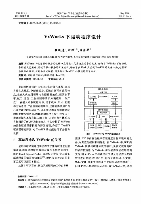
收稿 日期 : 0 91 - 2 0 —11 5
基金项 目:陕西省 自然科学基础研究计 划项 目“ 功耗 N C的核心技 术研究 ” 编号 :0 7 2 ) 微 电子预研 专项项 目 低 O ( 20 F 1 ;
( 编号 :100 0 11 ; 电子预研重点基金项 目( 5 38 150 ) 微 编号 :10 6 17 6 ) 94 A10 00 1 作者简介 : 强新建 (99 ) 男 , 16 一 , 讲师 , 学士 , 主要从事嵌 入式 开发 与应用研究.
文章 编号 :630 4 21 )30 8-3 17 -6 X(0 0 0 - 20 0
V W ok 下 驱 动 程 序 设 计 x rs
强新建 田泽 , , 淮治华
(. 1西安石油大学 计算机学院 , 陕西 西安 7 0 6 ; . 10 5 2 中国航空计算技术研 究所 , 陕西 西安 7 0 6 ) 10 8
如 图 2所 示 ,re F T u F S由核 心 层 ( oeL yr 和 C r ae )
3个 功 能层 , 即翻 译 层 ( r s t n L yr , T 层 Ta l i a e) M D n ao
摘 要 : x rs V Wok 下设备 驱动程 序 的设计 一直是 嵌入 式 系统 应 用 中的 热点. 绍 了 V Wok 介 x rs下标 准设 备 驱 动及其 原理 , 阐述 了驱动 程序 的开发 流程 , 出 了在 Fah上 实现 Tu F S的具 体 方法 , 给 ls re F 包括驱
等方 而考 虑 , 广泛 应用定 制硬 件 , 样就要 求用 户 自 这
雾囤謇
l l l I
己开发硬件的驱动程序. 设备驱动本身与操作系统 的相关 性特别 密切 , 因此 驱 动 程序 开 发 不仅 要 求 开 发者对 操作 系统有 深 入 的 了解 , 要 对 硬 件体 系 具 还
- 1、下载文档前请自行甄别文档内容的完整性,平台不提供额外的编辑、内容补充、找答案等附加服务。
- 2、"仅部分预览"的文档,不可在线预览部分如存在完整性等问题,可反馈申请退款(可完整预览的文档不适用该条件!)。
- 3、如文档侵犯您的权益,请联系客服反馈,我们会尽快为您处理(人工客服工作时间:9:00-18:30)。
大体上可把设备驱动程序分为两大类: 1. 基于I/O 文件系统的设备:包括基于I/O 系统的字符 设备和块设备。VxWorks 的I/O 系统有其独特性,因而它 比其它I/O 系统更快速、灵活,这在实时系统中非常重要。 这些设备都可采用ioLib 系统库提供的接口函数create()、 open()、close()、 read()、write()和 ioctl()来操作。 VxWorks 的I/O 系统由基本I/O 及含缓冲的I/O 组成,它 提供标准的C 库函数。基本I/O 库与Unix 兼容;而含缓 冲的I/O 则与ANSI C兼容。
VxWorks 设备驱动分类及特点
系统与驱动程序的关系
VxWorks 设备驱动分类及特点
当用户调用一种基本I/O 操作时,I/O 系统将用 户请求反映给特定驱动程序的相应操作函数。 驱动程序可调用该任务可执行的任何操作,包括 对其他设备进行I/O 操作。这意味着多数驱动程 序必须对关键程序代码采取一种互斥的操作机制。 通常采用的互斥机制是使用semlib 函数库提供的 信号量操作。
串口设备驱动——概述
一个包含了串行设备及其应用程 序的总体模型如图所示。从图中 可以看出,串行设备的驱动xxDrv 并不是直接和I/O 系统交互的, 中间存在一个ttyDrv(包括 tyLib)。实际上,与IO 系统交 互的不是xxDrv的函数而是 ttyDrv/tyLib 提供的函数。另外, TargetAgent 可以和xxDrv 交互, 方便了系统的调试。ttyDrv(包 括tyLib):可以称为一个虚拟的 设备驱动。它只是介于I/O 与底 层具体设备驱动之间,为系统提 供统一的串行设备界面。
VxWorks 设备驱动分类及特点
2. 其他特殊设备:主要指一些非基于I/O 文件系统的设 备,如串口、硬盘、网络设备等。不能通过标准I/O 来进 行存取,但都有它们各自相关的标准。 虽然VxWorks 的I/O 设备驱动与UNIX 的很类似,但两者 也有区别,主要包括以下几点: ● VxWorks 的设备驱动可以动态安装和卸载; ● 除了标准的输入、输出和错误输出外,VxWorks 的文 件描述符是全局的,可由任何任务存取; ● VxWorks 的设备驱动有优先级之分,这取决于调用它的 任务的优先级。而Unix 下的设备驱动则执行在系统模式 下,无优先级之分。
块设备驱动
块设备是指以“块”为 单位对数据进行存取的 设备。它可以被随机存 取,并且数据以块为单 位进行传输,典型的有 硬盘、光驱、软驱和磁 带等。 VxWorks 的块设备与字 符设备有微小的差别: 块设备不能与I/O 系统直 接打交道,如右图所示。
块设备驱动
块设备不能与I/O 系统直接打交道,如上图所示,在 块设备驱动程序与I/O 系统之间必须有文件系统,如 dosFs、rawFs 或tapeFs 等。这种层次关系允许同一 个块设备上存在不同的文件系统,从而减少驱动程序 中必须支持的I/O 函数的数量。 块设备驱动程序的操作函数大致有以下几个部分: 1. 低级驱动程序初始化; 2. 设备创建; 3. 读/写操作; 4. I/O 控制; 5. 复位及状态检测。
这7 个基本的I/O 操作函 数及其功能
字符设备驱动
驱动程序除了具有上述7 种基本I/O 操作函数 以外,还包含以下两种操作: ● 初始化函数负责在I/O 系统中安装驱动程序; 驱动程序将相应的设备与所需的资源关联起 来;然后初始化函数再执行其它任何必须的硬 件初始化操作。 ● 将驱动程序加载到I/O 系统中,这类函数一般 称作xxDevCreate()。一般简单的驱动程序, 往往将这两个函数合二为一。
串口设备驱动——ttyDrv 的层次结构
ttyDrv的数据流图:
串口设备驱动——ttyDrv 的层次结构
从图7-9 中可以清楚地看出系统的层次关系。应用层往往 调用通用的ioLib 中的函数(如:read、write、ioCtl 等)。这些函数从输入的文件描述符中找到相应的设备描 述符;然后找到设备驱动表,并调用设备驱动表中的处理 函数。而设备驱动表中的函ttyDrv/tyLib(tyWrite、 tyRead 等)则是第二层的内容。ttyDrv/tyLib 与实际的 设备(xxDrv)打交道完成指定的操作。第二层和底层的 通信是通过回调函数(callback)来实现的。具体来说, ttyDrv 提供两个函数(tyWrite 和tyRead):输出时底 层驱动可以从缓冲区中读取数据;输入时底层驱动可将接 收到的字符填入缓冲区。
串口设备驱动——串口驱动的编写
下图为CVT-PXA270 教学实验系统中蓝牙串口(BT_UART) 的电路原理图。它采用串行接口芯片MAX3244EAI。 MAX3244EAI为3 V~5 V 供电,EIA/TIA-232 与V.28/V.24 通信接口芯片,包含3 个发送、5 个接收电路,带自动关 断/唤醒功能,高数据传输速率。
常见的VxWorks 驱动程序
VxWorks 的提供了对很多设备的驱动程序支持。 下图为常见的VxWorks 设备驱动程序。
字符设备驱动
字符设备是指在I/O 传输 过程中以字符为单位进 行传输的设备,如键盘、 鼠标和打印机等。字符 设备驱动程序一般都有7 个基本I/O 操作函数,但 也不排除某些具体的字 符设备驱动程序可能忽 略其中的一个或几个操 作函数。
VxWorks 操作系统
第7章:VxWorks 驱动程序的编写
耿长青 2010.8.13
本章主要内容
介绍VxWorks 驱动程序的编写方法,包括字 符设备、块设备、串口设备、网络设备等的 驱动编写方法以及文件系统。本章安排了很多 实验,在学习过程中需要进行实践操作,这些 实验需要有第5 、6章的基础。
串口设备驱动——串口驱动的编写
PXA270 包含3 个串口:全功能串口、蓝牙串口以及标准 串口。由于RS-232-C 标准所定义的高、低电平信号与 PXA270 的UART 所定义的高、低电平信号完全不同。 PXA270 的UART 采用正逻辑方式。而RS-232-C 标准采用 负逻辑方式。显然,两者间要进行通信必须经过信号电平 的转换。
串口设备驱动——串口驱动的编写
CVT-PXA270 串口驱动的编写 编写串行设备的驱动主要有以下几个方面的工作: ● 初始化:确定系统要支持的串行通道的个数,初始化设 备描述符,编写设备初始化代码; ● 编写入口点函数; ● 编写设备中断服务程序(ISR); ● 修改sysSerial.c 文件。 1. 初始化过程 要编写设备的初始化代码,首先看一下系统初始化的大致 顺序,如下图所示。
串口设备驱动——ttyDrv 的层次结构
3. write() write()函数的调用过程是:write()→tyWrite()→xxDrv。 tyWrite 对所有的串行设备做同样的事情: ● 如果环形缓冲满,则阻塞; ● 从用户的缓冲中读数据到环形缓冲中; ● 在一定的情况下激活xxDrv 开始传输数据周期(一 个传输周期中首先传送数据到设备,然后等待设备给 出一个中断,以继续传送下一个数据); ● xxDrv 通过调用tyITx()来从输出环形缓冲中读数 据。
串口设备驱动——yDrv 的层次结构
4. read( ) read ()函数的调用过程是: read( )→tyRead( )→xxDrv。tyRead 对所有的 串行设备执行以下操作: ● 如果环形缓冲空,则阻塞; ● 从环形缓冲读数据到用户的缓冲中; ● 如果输入环形缓冲中还有字符,则启动所 有阻塞的进程; ● xxDrv 用tyIRx()来将设备读到的字符写 入到输入环形缓冲中
串口设备驱动——串口驱动的编写
从图中可以看出,串口设备的初始化涉及2 个阶段: (1) 在usrInit()中进行设备的初始化 sysHwInit()→sysSerialHwInit():进行设备资源的设置,初始化硬 件,并关闭串口中断; (2) 在usrRoot 中执行进一步操作 ● usrRoot()→SysSerialHwInit2():开启中断; ● usrIosCoreInit()→ttyDrv():进行系统调用,初始化ttyLib通 用驱动程序; ● usrIosCoreInit() → usrSerialInit()→ttyDevCreate() :创 建串口设备,其中创建时ttyDevCreate()的第二个参数SIO_CHAN 需 要使用sysSerialChanGet()获得。
串口设备驱动——概述
另外,还可调用具体 硬件的管理驱动。总 之ttyDrv 给系统提供 了一些通用的管理函 数(如缓冲管理和互 斥等)。所以ttyDrv 往往可以管理多个设 备。 右图表明了ttyDrv在 I/O系统中的作用。
串口设备驱动——ttyDrv 的层次结构
ttyDrv(tyLib)是一个虚拟的驱动,既管理着和 I/O 的交互,又管理与底层硬件驱动的交互。它 在与I/O 交换时所做的工作主要有:I/O 系统请 求初始化 (如添加设备入口,创建设备描述符)、 处理所有I/O 请求(如:ttyOpen、ttyIoctl、 tyRead 和tyWrite 等)、管理数据缓冲区和管理 多任务的同步和互斥。 ttyDrv 负责着ttyOpen 和ttyIoctl 的接入;而 tyLib 则负责tyRead 和tyWrite 的接入。下面这 个图为一个更加详细的、系统的数据流向图。
串口设备驱动——概述
串行设备驱动代码的分层结构图 vxWorks 的串行设备不同于前 面介绍的字符设备和块设备。 其驱动的结构如图 所示。从图 中可以看出:系统中的串行设 备驱动总共分3 层: usrConfig.c和ttyDrv(包括tyLib) 提供了一些对串行设备的一些 通用操作;而sysSerial.c 则针 对具体目标系统的、串行设备 有关的一些数据结构进行初始 化操作;最后xxDrv.c ( 在 cvtpxa270 BSP 中文件名为 pxa270FfnSio.c)包括了一些 具体设备相关的操作(如读/写 数据和设置等)。
