C8051f410串口通信接口设计实验
基于C8051f410的DS1302 实时时钟实验
// 地址,命令
DS1302_Input_Byte(((da/10)<<4)|(da%10));
// 写 1Byte 数据
DS1302_CLK = 1;
DS1302_RST = 0;
}
读一个字节和写一个字节有明显的不一样,先是写地址字节,然后再读数据字节,写地 址字节时上升沿有效,而读数据字节时下降沿有效,当然前提是 RST 信号必须拉高。写地 址字节和读数据字节同是 LSB 开始。
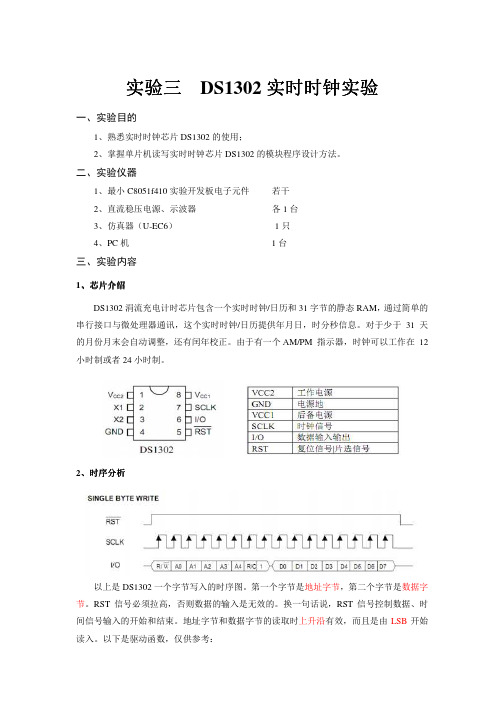
2、时序分析
以上是 DS1302 一个字节写入的时序图。第一个字节是地址字节,第二个字节是数据字 节。RST 信号必须拉高,否则数据的输入是无效的。换一句话说,RST 信号控制数据、时 间信号输入的开始和结束。地址字节和数据字节的读取时上升沿有效,而且是由 LSB 开始
读入。以下是驱动函数,仅供参考:
反过来的转化:(( timedata & 0x70) >> 4)*10 + ( timedata & 0x0F )。
四、实验现象和结果
1、接好硬件电路,编译运行程序,观察液晶 12864 显示如下内容,图中红色框内为显 示的年月日星期,时分秒。
图 12864 显示效果图
五、预习要求
1、读懂程序; 2、预先给出运算结果,以便和实验结果比较;
//写 DS1302,ucAddr 地址, ucData 要写的数据
void Write1302(unsigned char ucAddr, unsigned char da)
{
DS1302_RST = 0;
DS1302_CLK = 0;
DS1302_RST = 1;
DS1302_Input_Byte(ucAddr);
C8051F系列单片机串口通讯程序-推荐下载
C8051F系列单片机串口通讯程序采用C8051F020单片机//串口编程--接收PC发过来的字符串,回发字符串.发送期间中断控制LED灯闪烁//采用外部晶振22.1184MHz 使用定时器1,方式2产生波特率,SMOD = 0或者1 //定时器初值X=256-SYSCLK*(SMOD+1)/(BAUDRATE*384)/#include <C8051F020.h>sfr16 TMR3RL = 0x92; //定时器3重装载寄存器sfr16 TMR3 = 0x94; //定时器3计数器#define uchar unsigned char#define uint unsigned int//----------------------------------------------------------------------//参数设置区//----------------------------------------------------------------------#define BAUDRATE 4800 //波特率bps#define CLKOUT 22118400 //外部晶振,修改也要修改OSCXCN#define SMODVAL 0 //SMOD的值,修改请也修改PCONVAL#define PCONVAL 0x00 //PCON的值,=0x00时SMOD0=0; =0x80时SMOD0=1 #define TXVAL (256-CLKOUT*(SMODVAL+1)/BAUDRATE/384) //定时器初值#define MAX_LEN 10 //每次接收/发送字符串的长度//---------------------------------------------------------------------//全局变量//---------------------------------------------------------------------sbit LED = P1^6; //LED '1'亮'0'灭bit readFlag = 0; //读标志uchar readCounts = 0; //已经读取的字符个数,与MAX_LEN比较uchar idata trdata[MAX_LEN]; //要接收/发送的字符串//----------------------------------------------------------------------//子函数声明//----------------------------------------------------------------------void SYSCLK_Init(void); //系统时钟初始化void PORT_Init(void); //端口初始化void UART0_Init(void); //串口UART0初始化void Send_Char(uchar ch); //发送单个字符void Send_String(uchar * str, uint len); //发送一个字符串void UART0_ISR(); //串口中断服务程序,接收字符void Timer3_Init(uint counts); //定时器3初始化void Timer3_ISR(void); //定时器3中断服务程序//----------------------------------------------------------------------//主函数//----------------------------------------------------------------------void main(void){WDTCN = 0xde; //禁止看门狗WDTCN = 0xad;SYSCLK_Init(); //时钟初始化PORT_Init(); //端口初始化UART0_Init(); //串口初始化Timer3_Init(CLKOUT/12/10); //定时器初始化EA = 1; //开全局中断while(1){if(readFlag) //已经读取{readFlag = 0; //清零Send_String(trdata,MAX_LEN); //发送字符串}}}//----------------------------------------------------------------------//子函数具体实现//----------------------------------------------------------------------//系统时钟初始化void SYSCLK_Init(void){uint i;OSCXCN = 0x67; //采用外部晶振22.1184MHz,不分频. 选型OSCXCN=0110,0111 for(i=0;i<256;i++); //等待>1mswhile(!(OSCXCN&0x80)); //查询直到XTLVLD=1,晶振稳定OSCICN = 0x88; //切换到外部振荡器,允许时钟失效监测器. OSCICN=1000,1000 }//端口初始化void PORT_Init(void){XBR0 = 0x04; //允许UART0,RX,TX连到2个端口引脚. XBR0=0000,0100XBR1 = 0x00;XBR2 = 0x40; //交*开关使能P0MDOUT |= 0x03; //P0.0为推拉方式输出,即TX0,RX0所在的端口0000,0011P1MDOUT |=0x40; //P1.6为推拉方式输出,即LED所在的端口0100,0000}//串口初始化void UART0_Init(void){SCON0 = 0x50; //选择串口方式1,波特率可变SCON0=0101,0000TMOD = 0x20; //选择T1,方式2,自动再装入8位计数器TH1 = (int)TXVAL; //T1初值,根据波特率,时钟等计算. 0xF4, bps=4800bpsTL1 = (int)TXVAL;ES0 = 1; //UART0中断开启TR1 = 1; //启动定时器T1PCON |= PCONVAL; //PCON=0x00,SMOD = 0 ; PCON=0x80,SMOD=1 TI0 = 1; //声明TX0就绪,可以发送TR0 = 1;}//定时器初始化void Timer3_Init(uint counts){TMR3CN = 0x00; //禁止定时器T3,清TF3,采用SYSCLK/12为时基TMR3RL = -counts; //初始化重装载值TMR3 = 0xffff; //设置为立即重装载EIE2 |= 0x01; //T3中断开启TMR3CN |= 0x04; //启动T3}//发送单个字符void Send_Char(uchar ch){SBUF0 = ch; //送入缓冲区while(TI0 == 0); //等待发送完毕TI0 = 0; //软件清零}//发送字符串,调用Send_Char() len字符串长度void Send_String(uchar * str,uint len){uint k = 0;do{Send_Char(*(str + k));k++;} while(k < len);}//定时器3中断服务程序void Timer3_ISR(void) interrupt 14 using 0{TMR3CN &= ~(0x80); //清TF3LED = ~LED;}//UART0中断服务程序. 接收字符void UART0_ISR(void) interrupt 4 using 1{uchar rxch;if(RI0) //中断标志RI0=1 数据完整接收{RI0 = 0; //软件清零rxch = SBUF0; //读缓冲if(readCounts>=MAX_LEN){readCounts = 0;readFlag = 1;}trdata[readCounts] = rxch; //存入数组,供发送readCounts++;}}//-------------------------------------------------------------//程序结束。
C8051f410模数与数模转换器配置实验
万用表测试,以利于对比实验结果。 实验参考代码 D/A 转换:
#include <c8051f410.h>
// SFR declarations
sfr16 TMR3RL sfr16 TMR3 sfr16 IDA0
= 0x92; = 0x94; = 0x96;
// Timer3 reload value // Timer3 counter // IDA0 high and low bytes
TIMER3_Init(SYSCLK/SAMPLE_RATE_DAC);
EA = 1;
// Enable global interrupts
while(1) {} } 实验参考代码 A/D 转换: #include <c8051f410.h> #include <stdio.h>
// Wait for interrupt // SFR declarations
#define SYSCLK
24500000
// Internal oscillator frequency in Hz
#define SAMPLE_RATE_DAC 100000L
#define PHASE_PRECISION 65536
#define FREQUENCY
1000
// DAC sampling rate in Hz // range of phase accumulator // Frequency of output waveform in Hz
static unsigned phase_acc = 0;
// Holds phase accumulator
int SIN_temp; unsigned char index; phase_acc += PHASE_ADD; index = phase_acc >> 8; SIN_temp = SINE_TABLE[index];
USART通信接口设计实验

UART_Data = 0; } } }
四、实验现象和结果
1、把串口线和 PC 机连接起来,运行程序后,通过串口调试软件发送 ASCII 码字符(需 要以回车键结尾)到单片机实验板,单片机实验板接收到从串口调试软件发送过来的 ASCII
实验四 UART 通信接口设计实验
一、实验目的
1、理解用异步串行通信进行 RS232 通信的原理并能掌握其方法及编程;
2、学习使用定时器 T1 做波特率发生器,掌握计算波特率的方法。
二、实验仪器
1、自制的 C8051f410 实验开发板 1 块
2、直流稳压电源、示波器
各1台
3、仿真器(U-EC6)
1只
码字符后,又将同样的字符回送给串口调试软件,这样串口调试软件可以看到返回同样的字
符,如果收发的字符相同,则说明 PC 机与单片机实验板之间的通信成功,如下图所示。
注: 串口通信波特率、位数据位、停止位、校验等参数设置值参考上图。
五、预习要求
1、读懂程序; 2、预先给出修改代码,以便更快更好的得出实验结果;
4、PC 机
1台
三、实验内容
实验任务:编写程序将单片机的 P0.4、P0.5 口配置为串口 0 通信口,将 PC 机发送给
c8051f410 的数据原样发回 PC 机,程序中用“0x0d”作为帧尾标志。
PC 端发送、接收可采用串口接收软件“串口调试助手 V2.1”。
在程序中通过交叉开关配置 TX0,RX0 分别到 P0.4、P0.5 引脚,由于 I/O 口是 TTL 电 平信号,需要通过 MAX232 转换为 RS-232 电平后才能与 PC 机连接,连接电路如上图所示。
关于C8051F410的设计报告

2013年全国大学生电子设计大赛报告基于C8051F410单片机的设计摘要:微处理器在社会发展中扮演着非同寻常的角色,渗透到了各行各业。
经过不断的发展与创新,单片机大致可分为4位、8位、16位和32位。
C8051F410单片机片内集成了高频振荡源,并具备了多级分频系统以满足各种个性化的需要。
强大的非侵入式JTAG/C2调试手段,是传统仿真器调试模式所不能比拟的,可使内核和全部资源完全透明和可操作化,可以方便地完成下载和硬件仿真,且不占用内部片内资源。
芯片上除了P0~P2,还包括温度传感器和电源,晶振及片上温度传感器等外设集合为一体。
增加了交叉开关,可以灵活的将片内资源分配到I/O端口,3.3V的供电模式,内核的低电压使系统功耗进一步降低。
关键词:微处理器 C8051F410 传感器交叉开关Abstract:the microprocessor plays beautifully role in social development, penetrated into all walks of life. Through continuous development and innovation, SCM can be roughly divided into 4, 8, 16 and 32. C8051F410 micro controller on-chip integration of the high frequency oscillation source, and with the multi-level division system to meet the various needs of personalized. A powerful non-invasive JTAG/C2 debugging tools, is a traditional emulator debug mode can not match, can make the kernel and all the resources completely transparent and operational, can finish downloading and hardware simulation conveniently, and does not occupy the internal on-chip resources. Chip P0~P2 in addition, also includes a temperature sensor and a power supply, a crystal and on-chip temperature sensor is integrated peripherals such as set. Increase the crossbar switch, can be flexible to on-chip resource allocation to the I/O port, 3.3V low voltage power supply mode, the power consumption of the system to further reduce the kernel.Keywords: microprocessor C8051F410 sensor switch目录一、前言.............................. (1)二、总体方案设计...................... .. (1)1、方案设计....................... (1)2、方案论证与比较 ....................... (1)3、方案选择...................... (1)三、单元模块设计...................... .. (2)1、各单元模块功能介绍及电路设计......... .. (2)2、电路参数的计算及元器件的选择........................... .. (5)3、特殊器件的介绍................ . (6)4、各单元模块的联接.............. (7)四、系统调试.......................... .. (8)五、系统功能、指标参数......................... . (9)六、设计总结........................... .................................... .9七、参考文献............................ .................................. ..9八、附录 (9)1、电路原理图...................... .................................. .92、PCB图.......................................... ......... . (10)3、源程序.......................... (10)一、前言C8051F410器件是完全集成的低功耗混合信号片上系统型MCU,它的特性主要有:高速、流水线结构的8051兼容的微控制器核(可达50MIPS);高精度可编程的24.5MHz内部振荡器; 4个通用的16位定时器;硬件实时时钟(smaRTClock),工作电压可低至1V,带64字节电池后备RAM和后备稳压器。
C8051F410实验板使用手册【新】

一、C8051F410实验板原理图
二、C8051F410实验板装配说明
1、套件包括:元器件1袋(51个)、电路板1张(已经焊过贴片元件37个)、USB线1条;
2、,一般按照由低到高的顺序紧贴电路板焊接;
3、注意元器件的极性和方向问题;
4、红外发射LED、红外接收SM0038、温度测量DS18B20、LCD1602、LCD12864、串口连接线和纽扣电池等是预留做功能扩展的器件不包含在本套件中,暂时不必焊接。
三、C8051F410实验板照片
四、C8051F410实验板资源分布图
五、C8051F410实验板元件清单
名称
数量
说明
备注
贴片元件
和PCB板
C8051F410
1
已经焊接到电路板上了
1117-3.3
1
IN4148
2
10Ω
1
270Ω
8
510Ω
10
1KΩ
4
2.2KΩ
2
2.5KΩ
1
8050
1
22pF
2
0.1uF
4.7 uF
1
注意极性
10uF
8
注意极性
LED绿
1
注意极性
LED红
8
注意极性
按键
16
无极性
4
PCB板
1
电源线
USB线
1
直插元件
(共52个)
共阴四联数码管
2
注意方向
CH452
1
注意串口座(孔)
1
USB座
1
钮扣电池座
1
蜂鸣器
1
C8051f410利用SMBUS实现基于I2C器件操作实验
实验参 实验参考代码: 代码: #include <C8051F410.h> #define SYSCLK 24500000 #define SMB_FREQUENCY 50000 #define EEPROM_ADDR 0xA0 #define WRITE 0x00 #define READ 0x01 unsigned char bit WORD_ADDR; SMB_RW; // System clock frequency in Hz // SCL clock rate, between 10kHz and 100kHz // Device address(7 bits, lsb is a don't care). // SMBus WRITE command // SMBus READ command
// 是否伪读 // 时候重复发送 START 信号,轮询 // Timer3 reload registers // Timer3 counter registers
sbit LED = P0^5; sbit SDA = P0^2; sbit SCL = P0^3; void SMBus_Init (void) { SMB0CF = 0x5D; SMB0CF |= 0x80; }
// Used by the ISR to flag failed transfers // 收发字符个数 // Send a start
switch (SMB0CN & 0xF0) // Status vector { case 0xE0: // Master Transmitter/Receiver: START condition transmitted. SMB0DAT = EEPROM_ADDR; // Load address of the target slave SMB0DAT &= 0xFE; // Clear the LSB of the address for the R/W bit SMB0DAT |= SMB_RW; // Load R/W bit STA = 0; // Manually clear START bit i = 0; // Reset data byte counter break; case 0xC0: // Master Transmitter: Data byte (or Slave Address) transmitted if (ACK) // Slave Address or Data Byte Acknowledged? { if (SEND_START) { STA = 1; SEND_START = 0; break; } if(SMB_SENDWORDADDR) { SMB_SENDWORDADDR = 0; SMB0DAT = WORD_ADDR; if (SMB_RANDOMREAD) { SEND_START = 1; // Send a START after the next ACK cycle SMB_RW = READ;
80C51单片机串口通信(含原程序)
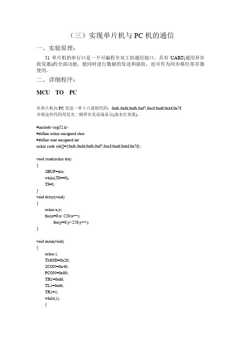
buf=NUMCODETAB[num];
transbyte(buf);
buf=NUMCODETAB[num];
transbyte(buf);
buf=NUMCODETAB[num];
transbyte(buf);
buf=NUMCODETAB[num];
transbyte(buf);
void send(uchar dat)
{
SBUF=dat;
while(TI==0);
TI=0;
}
void delay(void)
{
uchar x,y;
for(x=0;x<220;x++)
for(y=0;y<250;Leabharlann ++);}
void main(void)
{
uchar i;
TMOD=0x20;
SCON=0x40;
并将这些代码用发光二极管在发送端显示(流水灯效果)。
#include<reg52.h>
#define uchar unsigned char
#define uint unsigned int
uchar code tab[]={0xfe,0xfd,0xfb,0xf7,0xef,0xdf,0xbf,0x7f};
sbit DIPIN = P1^3;
uint num;
uchar receive (void)
{
uchar dat;
while(RI==0);
RI=0;
dat=SBUF;
SBUF=dat;
return dat;
}
unsigned char code NUMCODETAB[]={0xFC,0x60,0xDA,0xF2, //数字0,1,2,3
C8051F410单片机的设计

目录2011年硬件课程设计任务书 ...................................................... 错误!未定义书签。
摘要 .. (1)第1章概述 (2)1.1硬件实习的目的要求 (2)1.2热电偶简介 (2)1.3热电偶校验仪的意义 (3)第2章硬件设计 (4)2.1控制系统设计 (4)2.2供电系统设计 (5)2.3I/V转换、调整设计 (6)2.4按键接口电路 (8)2.5液晶接口电路 (9)第3章软件设计 (10)3.1C8051F410系统初始化 (10)3.2热电偶分度表查询设计 (11)3.315位DAC输出设计 (12)3.4按键接口设计 (12)3.5液晶显示程序设计 (13)第4章结论 (15)参考文献 (16)附录 (18)摘要在工业生产中,往往需要高温生产环境,此时我们可以利用热电偶直接测量工厂生产温度,并把温度信号转换成电压信号,通过仪表转换成被测介质的温度,以数字的形式直观的展现给作业工人。
基于C8051F410的热偶信号发生器是以C8051F410为控制核心的高精度热电偶温度转换仪。
可以利用它对实际生产使用的热电偶进行检查,以确保工业生产的安全、高效。
此课题设计中主要以Keil uVision开发软件和Protel软件绘制电路图作为开发平台。
设计中主要从硬件和软件两方面进行入手。
硬件设计主要包括对供电系统,I/V转换系统,按键输入和液晶显示系统的设计;软件设计包括C8051F410系统初始化,按键输入设计,热电偶分度表查询设计,DAC输出转换设计和液晶显示程序设计。
通过硬件和软件相结合的方式实现热电偶校验仪的精确工作。
关键词:C8051F410 工业生产热电偶第1章概述1.1 硬件实习的目的要求课程设计是学生理论联系实际的重要实践教学环节,是一次综合性专业设计训练。
通过课程设计可以使我们获得以下几方面能力: 1.进一步复习和巩固加深所学专业基础课及专业课理论知识,培养自身规划设计、理论计算、软件绘图、计算机应用、文献查阅、报告撰写等基本技能;2.培养实践动手能力及独立分析和解决工程实际问题的能力;3.培养团队协作精神、创新意识、严肃认真的治学态度和严谨求实的工作作风。
C8051F410例程简介

ADC 2个IDAC 1个外部中断Interrupts 1个PCA(可编程计数器阵列)6个PortIO 1个定时器Timer 7个UART 2个Watchdog 1个Oscillators 6个Comparators 1个SMBus 6个SPI 3个ADC例1:单通道输入程序描述:ADC0对P1.1端口输入电压采样2048次,累加后,求平均;结果通过UART输出,到电脑,串口调试程序,接收,显示。
ADC例2:多通道输入程序描述:使用ADC0内部多路选择器,逐个循环采样6个输入端口电压,并输出到电脑显示。
IDAC例:程序描述:使用IDAC输出一个正弦波。
Interrupts例:程序描述:配置外部中断INT0或INT1作为中断源,按键触发中断,执行中断程序(P0.0电平改变,连接在P0.0的LED亮灭)。
PCA例1:8位输出模式PWM波程序描述:利用PCA8位输出模式,输出PWM波。
PCA例2:16位输出模式PWM波程序描述:利用PCA16位输出模式,输出PWM波。
PCA例3:捕获模式程序描述:利用PCA捕获模式,测量输入引脚事件发生时间。
PCA例4:频率输出模式程序描述:利用PCA频率输出模式,产生一个方波,输出到端口。
PCA例5:高速输出模式(?)程序描述:利用PCA高速输出模式,产生一个方波,输出到端口。
PCA例6:软件定时器模式程序描述:利用PCA软件定时器模式,产生定时的中断;中断程序中,触发LED闪耀。
PortIO例1:端口匹配程序描述:配置端口匹配事件作为中断源,程序执行;当按键时,端口匹配事件触发中断,执行中断程序(触发LED亮)。
PortIO例2:数字输入/输出程序描述:演示怎样设置数字输入/输出方式;两个按键和两个LED分别连接到端口;程序持续检测按键,如果按键按下,则点亮下相应的LED。
Timer例1: 8位重载方式程序描述:演示如何使用定时器0的8位定时计数重载方式;利用定时器0在一定频率下产生一个中断,并且,当用户的中断计数到达选择值时,LED被触发。
C8051F410单片机的端口配置
5
2021/7/1
和普通单片机I/O的不同
2
2021/7/1
端口输入/输出
3
2021/7/1
端口输入/输出
从图18.1可以看出,C8051F410单片机之所以 可以实现内部数字资源的灵活分配,是通过优 先级交叉开关译码器实现,即图中的Priority Crossbar Decoder。
4
2021/7/1
和普通单片机I/O的不同
那么C8051F410单片机的I/O配置和普通的单片 机差别在哪里呢?我们用一个例子说明。
此外, C8051F410单片机的I/O端口在使用前 都要进行输入/输出的设置。
设置输入方式:模拟输入还是数字输入。 设置输出方式:漏极开路(open-drain)输出
还是推挽输出(push-pull)。
6
2021/7/1
优先权交叉开关译码器
优先权交叉开关译码器为每个I/O功能分配优 先权,从优先权最高的UART0开始。当一个数 字资源被选择时,尚未分配的端口引脚中的最 低位被分配给该资源(UART0除外,它总是被 分配到引脚P0.4和P0.5)。
17
2021/7/1
端口初始化步骤的注意事项
2)某个端口使用者有特殊的用处(而不是希 望用做PCA,UART,ECI等用途),比如你想将 P1.3用来驱动一个LED,此时你就要让交叉开 关译码器跳过P1.3,这样CrossBar在为内部数 字资源(比如PCA,UART,ECI等)分配端口时, 就会跳过P1.3。
关于C8051F410的设计报告

2013年全国大学生电子设计大赛报告基于C8051F410单片机的设计摘要:微处理器在社会发展中扮演着非同寻常的角色,渗透到了各行各业。
经过不断的发展与创新,单片机大致可分为4位、8位、16位和32位。
C8051F410单片机片内集成了高频振荡源,并具备了多级分频系统以满足各种个性化的需要。
强大的非侵入式JTAG/C2调试手段,是传统仿真器调试模式所不能比拟的,可使内核和全部资源完全透明和可操作化,可以方便地完成下载和硬件仿真,且不占用内部片内资源。
芯片上除了P0~P2,还包括温度传感器和电源,晶振及片上温度传感器等外设集合为一体。
增加了交叉开关,可以灵活的将片内资源分配到I/O端口,3.3V的供电模式,内核的低电压使系统功耗进一步降低。
关键词:微处理器 C8051F410 传感器交叉开关Abstract:the microprocessor plays beautifully role in social development, penetrated into all walks of life. Through continuous development and innovation, SCM can be roughly divided into 4, 8, 16 and 32. C8051F410 micro controller on-chip integration of the high frequency oscillation source, and with the multi-level division system to meet the various needs of personalized. A powerful non-invasive JTAG/C2 debugging tools, is a traditional emulator debug mode can not match, can make the kernel and all the resources completely transparent and operational, can finish downloading and hardware simulation conveniently, and does not occupy the internal on-chip resources. Chip P0~P2 in addition, also includes a temperature sensor and a power supply, a crystal and on-chip temperature sensor is integrated peripherals such as set. Increase the crossbar switch, can be flexible to on-chip resource allocation to the I/O port, 3.3V low voltage power supply mode, the power consumption of the system to further reduce the kernel.Keywords: microprocessor C8051F410 sensor switch目录一、前言.............................. (1)二、总体方案设计...................... .. (1)1、方案设计....................... (1)2、方案论证与比较 ....................... (1)3、方案选择...................... (1)三、单元模块设计...................... .. (2)1、各单元模块功能介绍及电路设计......... .. (2)2、电路参数的计算及元器件的选择........................... .. (5)3、特殊器件的介绍................ . (6)4、各单元模块的联接.............. (7)四、系统调试.......................... .. (8)五、系统功能、指标参数......................... . (9)六、设计总结........................... .................................... .9七、参考文献............................ .................................. ..9八、附录 (9)1、电路原理图...................... .................................. .92、PCB图.......................................... ......... . (10)3、源程序.......................... (10)一、前言C8051F410器件是完全集成的低功耗混合信号片上系统型MCU,它的特性主要有:高速、流水线结构的8051兼容的微控制器核(可达50MIPS);高精度可编程的24.5MHz内部振荡器; 4个通用的16位定时器;硬件实时时钟(smaRTClock),工作电压可低至1V,带64字节电池后备RAM和后备稳压器。
8051单片机 串口通讯实验
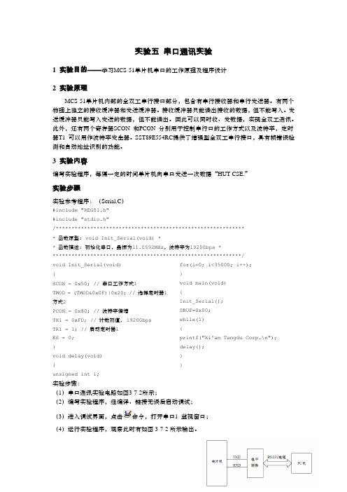
实验五串口通讯实验1 实验目的——学习MCS-51单片机串口的工作原理及程序设计2 实验原理MCS-51单片机内部的全双工串行接口部分,包含有串行接收器和串行发送器。
有两个物理上独立的接收缓冲器和发送缓冲器。
接收缓冲器只能读出接收的数据,但不能写入。
发送缓冲器只能写入发送的数据,但不能读出。
因此可以同时收、发数据,实现全双工通讯。
此外,还有两个寄存器SCON 和PCON 分别用于控制串行口的工作方式以及波特率,定时器T1 可以用作波特率发生器。
SST89E554RC提供了增强型全双工串行接口,具有帧错误检测和自动地址识别的功能。
3 实验内容编写实验程序,每隔一定的时间单片机向串口发送一次数据“HUT CSE.”实验步骤实验参考程序:(Serial.C)#include "REG51.h"#include "stdio.h"/************************************************************* 函数原型: void Init_Serial(void) ** 函数描述: 初始化串口,晶振为11.0592MHz,波特率为19200bps *************************************************************/void Init_Serial(void){SCON = 0x50; // 串口工作方式1TMOD = (TMOD&0x0F)|0x20; // 选择定时器1方式2PCON = 0x80; // 波特率倍增TH1 = 0xFD; // 计数初值, 19200bpsTR1 = 1; // 启动定时器1ES = 0;}void delay(void){unsigned int i;for(i=0; i<35000; i++);}void main(void){Init_Serial();SBUF=0x00;while(1){printf("Xi'an Tangdu Corp.\n"); delay();}}实验步骤:(1)串口通讯实验电路如图3-7-2所示;(2)编写实验程序,经编译、链接无误后启动调试;(3)进入调试界面,点击命令,打开串口1 监视窗口;(4)运行实验程序,观察此时有如图3-7-2所示输出。
C8051f410串口自环自检通信程序

void delay(uint time) { uint i,j; for(i=0;i<time;i++) for(j=0;j<300;j++) ; } void PCA_Init() { PCA0CN PCA0MD } void Port_IO_Init() { XBR0 = 0x01; XBR1 = 0x40; } void Oscillator_Init() { OSCICN = 0x87; } void UART0_Init (void) { SCON0 = 0x10;
ห้องสมุดไป่ตู้= 0x40; &= ~0x40;
// SCON0: 8-bit variable bit rate
// // // //
level of STOP bit is ignored RX enabled ninth bits are zeros clear RI0 and TI0 bits
新华龙电子 C8051F410 1 2 3 混合信号 ISP FLASH 微控制器 数据手册

C8051F410/1/2/3混合信号ISP FLASH微控制器数据手册潘琢金译Rev 0.7 2006.02版权所有新华龙电子有限公司 电话:0755-******** 83645242 传真: 0755-******** 1版权声明本手册中文版版权归译者和新华龙电子有限公司所有。
研究和开发人员可以自由使用本手册。
任何单位和个人未经版权所有者授权不得在任何形式的出版物中摘抄本手册内容。
原文中比较明显的错误已经在译文中更正。
译者将在本手册英文版更新后及时更新中文版内容。
译文中一定存在不少错误和不准确之处,望各位同仁不吝赐教,以便在新版本中更正。
译者联系方式:沈阳航空工业学院计算机学院潘琢金电话:024-********,130********Email:panzhuojin@或panzhj@2 新华龙电子有限公司 电话:0755-******** 83645242 传真: 0755-********C8051F410/1/2/3 混合信号ISP FLASH微控制器模拟外设−12位 ADC±1LSB INL;无失码可编程转换速率,最高200ksps可多达24个外部输入数据窗口中断发生器内建温度传感器−两个12位电流输出DAC−两个比较器可编程回差电压和响应时间可配置为唤醒或复位源上电复位/欠压检测器电压基准— 1.5V、2.2V(可编程)在片调试−片内调试电路提供全速、非侵入式的在系统调试(不需仿真器)−支持断点、单步、观察/修改存储器和寄存器−完全的开发套件供电电压 2.0V ~ 5.25V−内建LDO稳压器:2.1或2.5 V高速8051微控制器内核−流水线指令结构;70%的指令的执行时间为一个或两个系统时钟周期−速度可达50MIPS(时钟频率为50MHz时)−扩展的中断系统存储器−2304字节内部数据RAM(256+2048)−32/16KB FLASH;可在系统编程,扇区大小为512字节−64字节电池后备RAM(smaRTClock)数字外设−24个端口I/O;推挽或漏极开路,耐5.25 V电压−可同时使用的硬件SMBus(I2C兼容)、SPI和UART串口−4个通用16位计数器/定时器−16位可编程计数器/定时器阵列(PCA),有6个捕捉/比较模块和WDT−硬件实时时钟(smaRTClock),工作电压可低至1V,64字节电池后备RAM和后备稳压器时钟源−内部振荡器:24.5MHz,±2%精度,可支持UART操作;时钟乘法器可达50MHz−外部振荡器:晶体、RC、C、或外部时钟−smaRTClock振荡器:32KHz晶体或谐振器−可在运行中切换时钟源32脚LQFP或28脚5x5 QFN封装温度范围:-40°C - +85°C交叉开关新华龙电子有限公司 电话:0755-******** 83645242 传真: 0755-******** 1目录1 . 系统概述 (8)1.1CIP-51TM微控制器核 (12)1.1.1 与8051完全兼容 (12)1.1.2 速度提升 (12)1.1.3 增加的功能 (12)1.2片内调试电路 (13)1.3片内存储器 (14)1.4工作方式 (15)1.512位模/数转换器 (16)1.612位电流输出DAC (17)1.7可编程比较器 (17)1.8循环冗余检查单元 (18)1.9稳压器 (18)1.10串行端口 (18)1.11 SMA RTC LOCK(实时时钟) (19)1.12端口输入/输出 (20)1.13可编程计数器阵列 (21)2. 极限参数 (22)3. 总体直流电气特性 (23)4. 引脚和封装定义 (25)5. 12位ADC(ADC0) (33)5.1模拟多路选择器 (34)5.2温度传感器 (34)5.3工作方式 (35)5.3.1 转换启动方式 (35)5.3.2 跟踪方式 (35)5.3.3 时序 (36)5.3.4 跟踪方式 (38)5.3.5 输出转换码 (39)5.3.6 建立时间要求 (40)5.4可编程窗口检测器 (46)5.4.1窗口检测器 (47)6. 12位电流模式DAC(IDA0和IDA1) (50)6.1IDA0输出更新 (50)2 新华龙电子有限公司 电话: 0755-******** 83645242 传真: 0755-********6.1.1 On-Demand输出更新 (50)6.1.2 基于定时器溢出的输出更新模式 (51)6.1.3 基于CNVSTR边沿的输出更新模式 (51)6.2IDAC输出字格式 (51)6.3IDAC外部引脚连接 (55)7. 电压基准 (58)8. 稳压器(REG0) (61)9. 比较器 (63)10. CIP-51 微控制器 (73)10.1指令集 (74)10.1.1 指令和CPU时序 (74)10.1.2 MOVX指令和程序存储器 (74)10.2寄存器说明 (78)10.3电源管理方式 (81)10.3.1 空闲方式 (81)10.3.2 停机方式 (81)10.3.3 挂起方式 (81)11. 存储器组织和SFR (83)11.1程序存储器 (83)11.2数据存储器 (84)11.3通用寄存器 (84)11.4位寻址空间 (84)11.5堆栈 (84)11.6特殊功能寄存器 (85)12. 中断系统 (89)12.1MCU中断源和中断向量 (89)12.2中断优先级 (89)12.3中断响应时间 (89)12.4中断寄存器说明 (91)12.5外部中断 (96)13. 指令预取引擎 (98)14. 循环冗余检查单元(CRC0) (99)14.1CRC计算前的准备 (99)14.2执行CRC计算 (99)14.3访问CRC结果 (99)新华龙电子有限公司 电话:0755-******** 83645242 传真: 0755-******** 314.4CRC0的位反转功能 (100)15. 复位源 (103)15.1上电复位 (104)15.2掉电复位和VDD监视器 (105)15.3外部复位 (106)15.4时钟丢失检测器复位 (106)15.5比较器0复位 (106)15.6PCA看门狗定时器复位 (107)15.7FLASH错误复位 (107)15.8 SMA RTC LOCK(实时时钟)复位 (107)15.9软件复位 (107)16. FLASH存储器 (110)16.1FLASH存储器编程 (110)16.1.1 FLASH锁定和关键码功能 (110)16.1.2 FLASH擦除 (110)16.1.3 FLASH写 (111)16.2非易失性数据存储 (112)16.3安全选项 (112)16.4FLASH写和擦除指南 (115)16.4.1 VDD维护和VDD监视器 (115)16.4.2 PSWE维护 (116)16.4.3 系统时钟 (116)16.5FLASH读定时 (118)17.外部RAM (120)18. 端口输入/输出 (121)18.1 优先权交叉开关译码器 (122)18.2 端口I/O初始化 (125)18.3 通用端口I/O (129)19. 振荡器 (136)19.1可编程内部振荡器 (137)19.1.1 内部振荡器挂起方式 (137)19.2外部振荡器驱动电路 (139)19.2.1 外部振荡器直接用作定时器时钟 (139)19.2.2 外部晶体示例 (139)19.2.3 外部RC示例 (140)19.2.4 外部电容示例 (141)19.3时钟乘法器 (143)4 新华龙电子有限公司 电话: 0755-******** 83645242 传真: 0755-********19.4系统时钟选择 (145)20. SMARTCLOCK(实时时钟) (147)20.1 SMA RTC LOCK接口 (148)20.1.1 smaRTClock锁定和关键码功能 (148)20.1.2 使用RTC0ADR和RTC0DAT访问smaRTClock的内部寄存器 (148)20.1.3 smaRTClock接口的自动读功能 (149)20.1.4 RTC0ADR自动增1功能 (149)20.2 SMA RTC LOCK时钟源 (152)20.2.1 使用smaRTClock振荡器的晶体方式 (152)20.2.2 使用smaRTClock振荡器的自振荡方式 (152)20.2.3 自动增益控制(仅限于晶体方式) (153)20.2.4 smaRTClock偏置加倍 (153)20.2.5 smaRTClock时钟丢失检测器 (153)20.3 SMA RTC LOCK定时器和报警功能 (155)20.3.1 设置和读取smaRTClock定时器值 (155)20.3.2 设置smaRTClock报警值 (156)20.4后备稳压器和后备RAM (157)21. SMBUS (161)21.1支持文档 (162)21.2SMB US配置 (162)21.3SMB US操作 (163)21.3.1 总线仲裁 (163)21.3.2 时钟低电平扩展 (164)21.3.3 SCL低电平超时 (164)21.3.4 SCL高电平(SMBus空闲)超时 (164)21.4SMB US的使用 (164)21.4.1 SMBus配置寄存器 (165)21.4.2 SMBus控制寄存器 (168)21.4.3 数据寄存器 (171)21.5SMB US传输方式 (172)21.5.1 主发送器方式 (172)21.5.2 主接收器方式 (173)21.5.3 从接收器方式 (174)21.5.4 从发送器方式 (175)21.6SMB US状态译码 (176)22. UART0 (178)22.1增强的波特率发生器 (179)22.2工作方式 (181)新华龙电子有限公司 电话:0755-******** 83645242 传真: 0755-******** 522.2.1 8位UART (181)22.2.2 9位UART (182)22.3多机通信 (183)23. 增强型串行外设接口(SPI0) (188)23.1信号说明 (189)23.1.1 主输出、从输入(MOSI) (189)23.1.2 主输入、从输出(MISO) (189)23.1.3 串行时钟(SCK) (189)23.1.4 从选择(NSS) (189)23.2SPI0主方式 (191)23.3SPI0从方式 (192)23.4SPI0中断源 (192)23.5串行时钟时序 (193)23.6SPI特殊功能寄存器 (194)24. 定时器 (200)24.1定时器0和定时器1 (200)24.1.1 方式0 — 13位计数器/定时器 (200)24.1.2 方式1 (202)24.1.3 方式2 (202)24.1.4 方式3 (203)24.2定时器2 (208)24.2.1 16位自动重装载方式 (208)24.2.2 8位自动重装载定时器方式 (209)24.2.3 外部/smaRTClock捕捉方式 (210)24.3定时器3 (213)24.3.1 16位自动重装载方式 (213)24.3.2 8位自动重装载定时器方式 (214)24.3.3 外部/smaRTClock捕捉方式 (215)25. 可编程计数器阵列 (218)25.1PCA计数器/定时器 (219)25.2捕捉/比较模块 (221)25.2.1 边沿触发的捕捉方式 (222)25.2.2 软件定时器方式 (223)25.2.3 高速输出方式 (224)25.2.4 频率输出方式 (225)25.2.5 8位脉宽调制器方式 (226)25.2.6 16位脉宽调制器方式 (227)25.3看门狗定时器方式 (228)6 新华龙电子有限公司 电话: 0755-******** 83645242 传真: 0755-********25.3.1 看门狗定时器操作 (228)25.3.2 看门狗定时器的使用 (229)25.4PCA寄存器说明 (231)26. C2接口 (235)26.1C2接口寄存器 (235)26.2C2引脚共享 (237)新华龙电子有限公司 电话:0755-******** 83645242 传真: 0755-8364524371 . 系统概述C8051F41x器件是完全集成的低功耗混合信号片上系统型MCU。
实验六 8051单片机串行口实验

实验六8051单片机串行口实验一实验目的:理解8051单片机串行口工作原理和方式。
学习和掌握8051单片机实现通讯的环境和程序编写。
了解PC机通讯的基本要求。
二实验原理:在实时控制和管理方面,采用多台微机处理机组成分级分布控制系统中,各CPU之间的通信一般都是串行方式。
所以串行接口是微机应用系统常用的接口。
所谓“串行通信”是指外设和计算机间使用一根数据信号线(另外需要地线,可能还需要控制线),数据在一根数据信号线上一位一位地进行传输,每一位数据都占据一个固定的时间长度。
如图6-1所示。
这种通信方式使用的数据线少,在远距离通信中可以节约通信成本,当然,其传输速度比并行传输慢。
图6-1在串行通讯时,RS-232C接口是目前最常用的一种串行通讯接口,RS-232C使用-3到-25V表示数字“1”,使用3V到25V表示数字“0”,RS-232C在空闲时处于逻辑“1”状态。
8051单片机上有UART用于串行通信,发送时由TXD端送出数据,接收时则由RXD端输入数据。
它是一个可编程的全双工串行口。
SCON是串行口控制和状态寄存器,其格式如下:表6-1其中,SM0,SM1为串行口工作方式控制位,具体的工作方式如下表(表6-2)所示:表6-2SM2为多机通信控制位,当SM2=1时,只有接受到RB8为1,RI才置位,当SM2=0时,接受到字符RI就置位。
REN为串行口接收允许位。
工作在方式2和3时,TB8为发送的第9位数据,也可以用作奇偶校验位,RB8为接受到的第9位数据,而方式1时,RB8为接受到的停止位。
TI,RI分别为发送接受中断标志位,均由硬件置位,软件清0。
PCON是电源控制寄存器,其格式如下:表6-3其中,SMOD为串行口波特率加倍位。
当SMOD=1时,方式1,3波特率=定时器1溢出率/16,方式2波特率为fosc/32;当SMOD=0时,方式1,3波特率=定时器1溢出率/32,方式2波特率为fosc/64。
C8051F单片机和PC机串口通讯程序

C8051F单片机和PC机串口通讯程序//------------------------------------------------------------------//串口编程--接收PC发过来的字符串,回发字符串.发送期间中断控制LED灯闪烁//采用外部晶振22.1184MHz 使用定时器1,方式2产生波特率,SMOD = 0或者1//定时器初值X=256-SYSCLK*(SMOD+1)/(BAUDRATE*384)////程序编写: 郭郭//编程时间: 2005,12,30//最后修改: 2005,12,31//------------------------------------------------------------------#include <C8051F020.h>sfr16 TMR3RL = 0x92; //定时器3重装载寄存器sfr16 TMR3 = 0x94; //定时器3计数器#define uchar unsigned char#define uint unsigned int//------------------------------------------------------------------//参数设置区//------------------------------------------------------------------#define BAUDRATE 4800 //波特率bps#define CLKOUT 22118400 //外部晶振,修改也要修改OSCXCN#define SMODVAL 0 //SMOD的值,修改请也修改PCONVAL#define PCONVAL 0x00 //PCON的值,=0x00时SMOD0=0; =0x80时SMOD0=1#define TXVAL (256-CLKOUT*(SMODVAL+1)/BAUDRATE/384) //定时器初值#define MAX_LEN 10 //每次接收/发送字符串的长度//------------------------------------------------------------------//全局变量//------------------------------------------------------------------sbit LED = P1^6; //LED '1'亮 '0'灭bit readFlag = 0; //读标志uchar readCounts = 0; //已经读取的字符个数,与MAX_LEN比较uchar idata trdata[MAX_LEN]; //要接收/发送的字符串//------------------------------------------------------------------//子函数声明//------------------------------------------------------------------void SYSCLK_Init(void); //系统时钟初始化void PORT_Init(void); //端口初始化void UART0_Init(void); //串口UART0初始化void Send_Char(uchar ch); //发送单个字符void Send_String(uchar * str, uint len); //发送一个字符串void UART0_ISR(); //串口中断服务程序,接收字符void Timer3_Init(uint counts); //定时器3初始化void Timer3_ISR(void); //定时器3中断服务程序//------------------------------------------------------------------//主函数//------------------------------------------------------------------void main(void){WDTCN = 0xde; //禁止看门狗WDTCN = 0xad;SYSCLK_Init(); //时钟初始化PORT_Init(); //端口初始化UART0_Init(); //串口初始化Timer3_Init(CLKOUT/12/10); //定时器初始化EA = 1; //开全局中断while(1){if(readFlag) //已经读取{readFlag = 0; //清零Send_String(trdata,MAX_LEN); //发送字符串}}}//------------------------------------------------------------------//子函数具体实现//------------------------------------------------------------------//系统时钟初始化void SYSCLK_Init(void){uint i;OSCXCN = 0x67; /采用外部晶振22.1184MHz,不分频. 选型OSCXCN=0110,0111for(i=0;i<256;i++); //等待>1mswhile(!(OSCXCN&0x80)); //查询直到XTLVLD=1,晶振稳定OSCICN = 0x88;//切换到外部振荡器,允许时钟失效监测器. OSCICN=1000,1000}//端口初始化void PORT_Init(void){XBR0 = 0x04; //允许UART0,RX,TX连到2个端口引脚. XBR0=0000,0100XBR1 = 0x00;XBR2 = 0x40; //交叉开关使能P0MDOUT |= 0x03; //P0.0为推拉方式输出,即TX0,RX0所在的端口 0000,0011P1MDOUT |=0x40; //P1.6为推拉方式输出,即LED所在的端口0100,0000}//串口初始化void UART0_Init(void){SCON0 = 0x50; //选择串口方式1,波特率可变SCON0=0101,0000TMOD = 0x20; //选择T1,方式2,自动再装入8位计数器TH1 = (int)TXVAL;//T1初值,根据波特率,时钟等计算. 0xF4,bps=4800bpsTL1 = (int)TXVAL;ES0 = 1; //UART0中断开启TR1 = 1; //启动定时器T1PCON |= PCONVAL; //PCON=0x00,SMOD = 0 ; PCON=0x80,SMOD=1TI0 = 1; //声明TX0就绪,可以发送TR0 = 1;}//定时器初始化void Timer3_Init(uint counts){TMR3CN = 0x00; //禁止定时器T3,清TF3,采用SYSCLK/12为时基TMR3RL = -counts; //初始化重装载值TMR3 = 0xffff; //设置为立即重装载EIE2 |= 0x01; //T3中断开启TMR3CN |= 0x04; //启动T3}//发送单个字符void Send_Char(uchar ch){SBUF0 = ch; //送入缓冲区while(TI0 == 0); //等待发送完毕TI0 = 0; //软件清零}//发送字符串,调用Send_Char() len字符串长度void Send_String(uchar * str,uint len){uint k = 0;do{Send_Char(*(str + k));k++;} while(k < len);}//定时器3中断服务程序void Timer3_ISR(void) interrupt 14 using 0{TMR3CN &= ~(0x80); //清TF3LED = ~LED;}//UART0中断服务程序. 接收字符void UART0_ISR(void) interrupt 4 using 1{uchar rxch;if(RI0) //中断标志 RI0=1 数据完整接收{RI0 = 0; //软件清零rxch = SBUF0; //读缓冲if(readCounts>=MAX_LEN){readCounts = 0;readFlag = 1;}trdata[readCounts] = rxch; //存入数组,供发送readCounts++;}}//-------------------------------------------------------------//程序结束//--------------------------------------------------------------。
C8051F410实验指导书(2012)
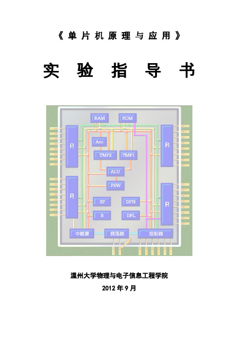
Oscillator_Init();
Interrupts_Init();
}
main()
{
Init_Device();
while(1);
}
void TIME0(void) interrupt INTERRUPT_TIMER0 //外部中断程序
{
P1^=0x01;
}
2、定时器2初始化由函数来实现,对定时器的工作方式、时钟等进行配置,使定时器2工作在16位重载的方式,实现500ms精确定时,定时器初值= M - tc/T,并用示波器进行观察,并通过LED闪烁显示(1s钟闪烁一次)。
{
ledP04=1;
ledP05=0;
delay(500);
ledP04=0;
ledP05=1;
delay(500);
} }
4、编写相应的水平垂直校验码校验的纠错程序。将上节课程序中的校验码结果的任何一位取反后,输入水平垂直校验码校验及纠错程序,观察校验结果,并纠错。
四、预习要求
1、熟悉交叉开关的配置方法
{
OSCICN = 0x87;
CLKSEL = 0x00;
}
void PORT_Init (void)
sfr16 PCA0CP0 =;
sfr16 TMR2RL = 0xCA; //T2寄存器
sfr16 TMR2= 0xCC;
sbit TEST_OUT = P0^1;
static unsigned int capture_period;
void OSCILLATOR_Init (void)//配置系统时钟24500000Hz
参考代码:(红色代码处不完整,请自己补全)
- 1、下载文档前请自行甄别文档内容的完整性,平台不提供额外的编辑、内容补充、找答案等附加服务。
- 2、"仅部分预览"的文档,不可在线预览部分如存在完整性等问题,可反馈申请退款(可完整预览的文档不适用该条件!)。
- 3、如文档侵犯您的权益,请联系客服反馈,我们会尽快为您处理(人工客服工作时间:9:00-18:30)。
1、改动代码使串口通信波特率为 115200,将原代码中采用中断方式接收字符的代码改 为采用查询方式接收、采用查询方式发送字符的代码改为采用中断方式发送,程序实现的功 能保持不变。
// WDTE = 0 (clear watchdog timer enable) // Initialize Port I/O // Initialize Oscillator
EA = 1;
while(1) {
if((UART_Data != 0) && (Byte == 13)) {
for(i=0;i<UART_Data;i++) {
TH1 = 0x96; CKCON &= ~0x0B;
TL1 = TH1; TMOD &= ~0xf0; TMOD |= 0x20; TR1 = 1;
// init Timer1 // TMOD: timer 1 in 8-bit autoreload
// START Timer1
IP |= 0x10; ES0 = 1;
// Clear interrupt flag // Read a character from UART // Store in array
void main (void) {
unsigned char i; PCA0MD &= ~0x40; PORT_Init(); SYSCLK_Init (); UART0_Init();
码字符后,又将同样的字符回送给串口调试软件,这样串口调试软件可以看到返回同样的字
符,如果收发的字符相同,则说明 PC 机与单片机实验板之间的通信成功,如下图所示。
注: 串口通信波特率、位数据位、停止位、校验等参数设置值参考上图。
五、预习要求
1、读懂程序; 2、预先给出修改代码,以便更快更好的得出实验结果;
实验二 UART 通信接口设计实验
一、实验目的
1、理解用异步串行通信进行 RS232 通信的原理并能掌握其方法及编程;
2、学习使用定时器 T2 做波特率发生器,掌握计算波特率的方法。
二、实验仪器
1、自制的 C8051f410 实验开发板 1 块
2、直C6)
1只
实验参考代码: #include <c8051f410.h>
// SFR declarations
#define SYSCLK
24500000
#define BAUDRATE
9600
// SYSCLK frequency in Hz // Baud rate of UART in bps
unsigned char UART_Buffer[64]; unsigned char UART_Data = 0; static char Byte;
// P0.4 digital push-pull // P0.5 digital open-drain void PORT_Init (void) {
P0MDOUT |= 0x10; XBR0 = 0x01; XBR1 = 0x40; }
UART TX UART RX
// Enable UTX as push-pull output // Enable UART on P0.4(TX) and P0.5(RX) // Enable crossbar and weak pull-ups
4、PC 机
1台
三、实验内容
实验任务:编写程序将单片机的 P0.4、P0.5 口配置为串口 0 通信口,将 PC 机发送给
c8051f410 的数据原样发回 PC 机,程序中用“0x0d”作为帧尾标志。
PC 端发送、接收可采用串口接收软件“串口调试助手 V2.1”。
在程序中通过交叉开关配置 TX0,RX0 分别到 P0.4、P0.5 引脚,由于 I/O 口是 TTL 电 平信号,需要通过 MAX232 转换为 RS-232 电平后才能与 PC 机连接,连接电路如上图所示。
// Make UART high priority // Enable UART0 interrupts
}
void UART0_Interrupt (void) interrupt 4 {
if (RI0 == 1) {
RI0 = 0; Byte = SBUF0; UART_Buffer[UART_Data] = Byte; UART_Data++; } }
SBUF0 = UART_Buffer[i]; while(!TI0); TI0 = 0; }
UART_Data = 0; } } }
四、实验现象和结果
1、把串口线和 PC 机连接起来,运行程序后,通过串口调试软件发送 ASCII 码字符(需 要以回车键结尾)到单片机实验板,单片机实验板接收到从串口调试软件发送过来的 ASCII
void SYSCLK_Init (void) {
OSCICN = 0x87; RSTSRC = 0x04; }
// configure internal oscillator for 24.5MHz // enable missing clock detector
// Configure the UART0 using Timer1, for <BAUDRATE> and 8-N-1.
void UART0_Init (void)
{
SCON0 = 0x10;
// SCON0: 8-bit variable bit rate
//
level of STOP bit is ignored
//
RX enabled
//
ninth bits are zeros
//
clear RI0 and TI0 bits
