第七章_参数化绘图
AutoCAD参数化绘图技术在测绘工程中的应用

AutoCAD参数化绘图技术在测绘工程中的应用摘要本文从参数化绘图的理念和地籍图管理在Auto CAD的相关理论基础出发,主要介绍了Auto CAD在地籍图管理的绘图过程、Auto LISP语言在对Auto CAD 实体对象的操作和Auto LISP参数化绘图在测绘工程中的应用等方面,通过利用Auto LISP语言在Auto CAD系统进行二次开发,只要是能运行Auto CAD的操作系统均能够运行,不仅提高了制图的效率与质量,而且能够减少在其他软件生产相同地籍成果的误差,有效地满足了测绘工作人员在参数化绘图方面的需求。
关键词:参数化绘图,Auto LISP语言,AutoCAD1 Auto CAD参数化绘图1.1 Auto CAD基本概念Auto CAD(Auto desk Computer Aided Design)是Auto desk(欧特克)公司开发的自动计算机辅助设计软件,用于二维绘图等功能,现已经成为最流行的绘图工具。
Auto CAD具有良好的用户界面,通过交互菜单或命令行方式便可进行各种操作。
通过它无需懂得编程,即可自动制图,因此它在全球广泛使用,可以用于土木建筑,装饰装潢,工业制图,工程制图,电子工业等多方面领域[9]。
1.2 Auto CAD二次开发的现实意义与基本原则1.2.1 Auto CAD二次开发的现实意义通过对Auto CAD系统的初步了解,相信许多人都已经对Auto CAD其强大的绘图与制图能力有所了解,但是根据本人在校期间的课程学习以及校外实践参与到生产工作的经验来看,如今越来越多的人虽说都认识Auto CAD系统,无论男女老少都知道“CAD”这个脍炙人口的名词,甚至也有很多人会利用这个强大的绘图软件制作用户所需要的产品,但是这些人有大部分不知道Auto CAD系统内部配置有二次开发工具Auto LISP语言,他们很多都是利用Auto CAD最基础的绘图功能与命令完成各自所需的图形,殊不知二次开发工具Auto LISP对许多工作上的繁琐性、重复性有所减免。
参数化方法 CAD设计课件
, xn , d1) 0 , xn, d2) 0
, xn, d3) 0
式中d1, d2, …, dn表示几何约束的值
49
上述方程组可以简写为
Fi (X, D) 0, i 1, 2, 3, ... , n
L1
L1
L2
L2
L2
L1
L1
L2
25
两圆相切约束(tangency) -两圆外切 (TAN_CC,C1,C2,+1) -两圆内切 (TAN_CC,C1,C2,-1)
线圆相切约束 -线圆相切,圆心在直线的 正半平面 (TAN_LC,L,C,+1) -线圆相切,圆心在直线的 负半平面 (TAN_LC,L,C,-1)
D=20
D=19.5
H=29.3
面积 S=900
面积 S=300
(a)
(b)
36
参数化设计(PD)&变量化设计(VD) 共同点:
1)解决几何图形约束和工程约束问题 2)尺寸变动时能自动更新图形;尺寸驱动功能
区别:
体现在约束方程的定义和求解方式上 PD:约束方程定义和求解有赖于创建时的顺序;参数 求解顺序、过程式(不可逆)求解策略 VD:约束的指定是陈述性的;通常采用并行求解策略
约束联动 图形特征联动 相关参数联动
41
图形特征联动
所谓图形特征联动就是保证在图形拓扑关系(连续、相切 、垂直、平行等)不变的情况下,对次约束的驱动
42
相关参数联动
所谓相关参数联动就是建立次约束与主约束在数值上和逻 辑上的关系
43
实现尺寸驱动的关键,在于尺寸链的求解
44
当修改某一尺寸时,系统自动检索该尺寸在尺寸 链中的位置,找到它的起始几何元素和终止几何 元素,使它们按新尺寸值进行调整,得到新模型; 接着检查所有几何元素是否满足约束,如不满足, 则让拓扑约束不变,按尺寸约束递归修改几何模 型,直到满足全部约束条件为止
参数化绘图

(3)同心:可以使将选择的圆,圆弧或多段线保持几何连续性。 选择“参数化”选项卡,在“几何”面板,单击 按钮,选择同心约束功
能 命令行:<同心>;Concentric 选择第一个对象; 选择第二个对象;
(4)固定:可以将一个点或一条曲线固定到相对于世界坐标系的指定位 置和方向上。 选择“参数化”选项卡,在“几何”面板,单击 按钮,选择固定约束功 能
图3-7 自动约束
3.动态约束 动态约束:默认情况下,标注约束是动态的,并具有以下特征: ① 缩小或放大时大小不变 ② 可以轻松打开或关闭 ③ 以固定的标注样式显示 ④ 提供有限的夹点功能 ⑤ 打印时不显示
4.几何约束
几何约束共有12项,其创建后,可以限制可能会违反约束的所有更
(1)重合:可以使一点位于曲线或延长线上,也可以使约束点与某个对象重 合。
•
2.用于确定二维对象之间或对象上的各点之间的几何关系。
• 标注约束:1.控制对象的距离,长度,角度和半径值 。
•
2.指约束对象上的两个点或不同对象上两点之间的距离。
它可以确定对象、对象上的点之间的距离或角度,也可以确定对象的
大小。
在使用参数化测图前,要对各项约束进行设置。 点击“几何”面板或“标注”面板右下角的小斜箭头,弹出“约束设置”
图3-4 几何约束设置
(2)标注约束设置:在打开“标注”选项卡,系统默认的“显示所有动态 约束”和“为选定对象显示隐藏的动态约束”用户可根据自己需要设置是否 显示。当选择“显示所有动态约束”时,为选定对象显示隐藏的动态约束选 项不起作用,当不选“显示所有动态约束”时,可选中“为选定对象显示隐 藏的动态约束”,实现需要时才显示。如图3-5为标注约束设置。
第七讲 参数化绘图工具

形体分析 ***分析已知圆弧、中间圆弧、连接圆弧 已知圆接圆 弧
已知 圆弧
已知 圆弧
连接圆 弧 连接线 段
练习三
1、参照下图绘制轮廓,注意其中的水平、 、参照下图绘制轮廓,注意其中的水平、 对称、相切等几何关系。 对称、相切等几何关系。
A 67 B 4 C 36 D 39
命令: area 指定第一个角点或 [对象(O)/加(A)/减(S)]: a 指定第一个角点或 [对象(O)/减(S)]: o (“加”模式) 选择对象: 选择多段线 (1) 面积 = 0.34, 圆周长 = 2.71 总面积 = 0.34 (“加”模式) 选择对象: 按 ENTER 键 指定第一个角点或 [对象(O)/减(S)]: s 指定第一个角点或 [对象(O)/加(A)]: o (“减”模式) 选择对象: 选择下面的圆 (2) 面积 = 0.02, 圆周长 = 0.46 总面积 = 0.32 (“减”模式) 选择对象: 选择上面的圆 (3) 面积 = 0.02, 圆周长 = 0.46 总面积 = 0.30 (“减”模式) 选择圆或多段线: 按 ENTER 键 指定第一个角点或 [对象(O)/加(A)]: 按 ENTER 键
练习三: 练习三:
A
B
C
D
52
32
98
15
练习五: 练习五:
A 92
B 50
C 36
D 39
E 18
练习四: 练习四:
A
B
C
D
130 50
30
15
AutoCAD 2010
第七讲 参数化绘图工具及 查询命令的使用
练习一
一、参数化绘图
1、约束水平几何 2、约束竖直几何 3、约束垂直几何 4、约束重合几何 还可以进行尺寸约束
先闻~参数化绘图示例

参数化绘图示例为了使用户能够更好在CAD下绘制各种自定义节点图,先闻CAD工具箱为用户提供强大的自定义参数化节点绘图脚本系统。
用户只需要简单了绘图系统,定义输入,输出语句,使用条件控制,循环控制语句,就可以完成以前需要大量时间、大量工序的绘图工作。
先闻CAD工具箱自身附带的绘图功能全部就是使用此绘图系统。
一、准备工作1、电脑上需安装AutoCAD,先闻CAD工具箱目前支持AutoCAD 2000到AutoCAD2012;2、到先闻公司网站下载并安装CAD工具箱,请到官方网站下载最新版软件,网站地址:/Textwebindex/Software/SoftwareCenter.aspx网页面如图:安装完成后,AutoCAD下应该有这样的界面:二、编制绘图节点打开系统自带的记事本,并写入以下语句:<?xml version="1.0" encoding="UTF-8"?><Modules TypeName="我的分类" ><Module Name="模块一" Author="小明" ><Input></Input><Output>点此下载</Output></Module></Modules>如下图所示:现在,把焦点集中到“模块一”下面,有两个子项:“Input ”和“Output ”。
“Input ”表示参数输入,绘图所需的参数均在此子项下定义,比如:定义一个插入点:<point name="InsertPoint" caption="插入点" defaultValue="0,0" />定义长度,宽度:<real name="length" caption="长度" defaultValue="500" /><real name="width" caption="宽度" defaultValue="400" />“Output ” 表示绘图输出,绘图输出语句归并到此项下,比如,根据上面的输入参数,绘制一个矩形: <line startPoint="InsertPoint+Point(length/2.0, width/2.0)"endPoint=" InsertPoint+Point(length/2.0, -width/2.0)" />endPoint=" InsertPoint+Point(-length/2.0, -width/2.0)" /> <line startPoint="InsertPoint+Point(-length/2.0, -width/2.0)"endPoint=" InsertPoint+Point(length/2.0, width/2.0)" /> <line startPoint="InsertPoint+Point(-length/2.0, width/2.0)"endPoint=" InsertPoint+Point(length/2.0, width/2.0)" />如下图所示:分类名称模块名称作者线段起点线段终点就这样,一个简单、完整的绘图节点就完成了。
机械识图与AutoCAD技术基础电子教案

机械识图与AutoCAD技术基础电子教案第一章:机械识图基础1.1 认识图纸:介绍图纸的种类、作用以及图纸的构成要素。
1.2 投影原理:讲解中心投影和平行投影的基本原理。
1.3 视图与投影视图:介绍基本视图、斜视图、投影视图的画法及标注。
1.4 剖视图与断面图:讲解剖视图、断面图的画法及标注方法。
第二章:机械制图标准2.3 公差与配合:介绍公差、配合的基本概念及标注方法。
2.4 形位公差与表面粗糙度:讲解形位公差、表面粗糙度的标注方法。
第三章:AutoCAD 2024基础知识3.1 AutoCAD 2024界面与操作:介绍AutoCAD 2024界面、工具栏及基本操作。
3.2 图形绘制基础:讲解点、线、圆等基本图形的绘制方法。
3.3 坐标系与坐标输入:介绍坐标系、坐标输入方法及坐标变换。
3.4 视图控制与图层管理:讲解视图控制、图层创建、修改与控制方法。
第四章:机械零件图绘制4.1 轴类零件图:绘制轴类零件图的步骤与技巧。
4.2 齿轮类零件图:绘制齿轮类零件图的步骤与技巧。
4.3 轴承类零件图:绘制轴承类零件图的步骤与技巧。
4.4 箱体类零件图:绘制箱体类零件图的步骤与技巧。
第五章:装配图绘制5.1 装配图概述:介绍装配图的作用、种类及绘制要求。
5.2 装配图的绘制方法:讲解装配图的绘制步骤与技巧。
5.3 爆炸图与透视图:介绍爆炸图、透视图的绘制方法。
5.4 装配图的修改与打印:讲解装配图的修改方法及打印设置。
第六章:AutoCAD实体绘图6.1 二维实体:介绍二维实体的创建方法,如矩形、圆形、多边形等。
6.2 三维实体:讲解三维实体的创建方法,如长方体、球体、圆柱体等。
6.3 实体编辑:介绍实体编辑工具的使用,如移动、旋转、缩放、布尔运算等。
第七章:机械工程图样标准7.1 标准件和常用件:介绍标准件和常用件的图样表示方法。
7.2 零件图的完整性:讲解零件图应包含的内容,如视图、尺寸、公差等。
7.3 装配图的完整性:讲解装配图应包含的内容,如总装图、零件表等。
现代设计方法简答题
现代设计方法简答题现代设计方法简答题集1.参数化绘图有何优点,常用的实现方法有那几种参数化绘图的优点是使得设计图可以随着某些结构尺寸的修改和使用环境的变化而变化,工作效率高。
常用的设计方法又:作图规则匹配法、几何作图局部求解和辅助线作图法。
2.参数化绘图方法中的几何作图局部求解法的核心思想是:1)在交互作图过程中随时标注每个新增加几何元素的自由度和所受的约束关系;2)判断几何求解的局部条件是否充分,通过遍历检测,依次解出条件成熟的元素参数;3)当图形的尺寸标注完整时,用批处理程序经过多遍扫描,解出绘图需要的所有未知数。
3.什么是优化设计?简述优化设计的分类。
答:优化设计亦称为最优化设计,它是以数学规划理论为基础,以电子计算机为辅助工具的一种设计方法。
宏观世界首先将设计按规定的格式建立数学模型,并选择合适的优化方法,选择或编制计算机程序,然后通过电子计算机计算自动获得最优化设计方案。
优化方法大体上可分为两类:(1)计算目标函数值,比较目标函数值,并以之作为抚今迭代、收敛根据的方法。
(2)变量函数极值理论为基础利用目标函数的以性态,并以之作为寻优、迭代收敛根据的方法。
4.最常用的数据模型有那几种?其特点各是?1)层次性。
指记录间是树型的组织结构。
它体现了记录间的“一对多”的关系。
具有结构简单。
清晰的特点,适用于记录之间本身就存在一种自然的层次关系,但是它难于处理记录之间的复杂关系。
2)网络型。
指事物之间为网络的结构组织。
它体现了记录之间的“多对多”的关系。
网络型机构能处理事物之间非常复杂的关系,但是模型结构也是极其复杂的3)关系型。
它是以集合论中的“关系”的概念为理论基础,指把信息集合定义为一张二维的组织结构,每一张二维表成为一个关系,表中的每一行为一个记录,每一列为数据项。
关系型的模型结构组织比较简单但是能处理复杂的事物之间的联系。
5.什么是数据模型?常用的数据模型有哪三种?答:数据模型是指数据库内部数据的组织方式,它描述了数据之间的各种联系,也是数据的高度结构化的表现。
用AutoCAD实现参数化自动绘图
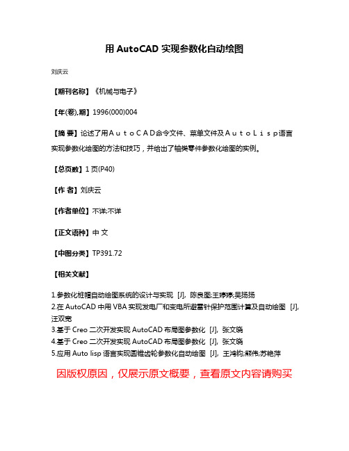
用AutoCAD实现参数化自动绘图
刘庆云
【期刊名称】《机械与电子》
【年(卷),期】1996(000)004
【摘要】论述了用AutoCAD命令文件、菜单文件及AutoLisp语言
实现参数化绘图的方法和技巧,并给出了轴类零件参数化绘图的实例。
【总页数】1页(P40)
【作者】刘庆云
【作者单位】不详;不详
【正文语种】中文
【中图分类】TP391.72
【相关文献】
1.参数化桩帽自动绘图系统的设计与实现 [J], 陈良图;王婷婷;吴扬扬
2.在AutoCAD中用VBA实现发电厂和变电所避雷针保护范围计算及自动绘图 [J], 汪双宽
3.基于Creo二次开发实现AutoCAD布局图参数化 [J], 张文晓
4.基于Creo二次开发实现AutoCAD布局图参数化 [J], 张文晓
5.应用Auto lisp语言实现圆锥齿轮参数化自动绘图 [J], 王鸿钧;熊伟;苏艳萍
因版权原因,仅展示原文概要,查看原文内容请购买。
AutoCAD计算机辅助设计 第7章 参数化绘图

7.2 尺寸约束
本节将介绍添加及编辑尺寸约束的方 法。
7.2.1 添加尺寸约束 7.2.2 编辑尺寸约束 7.2.3 用户变量及方程式
7.2.1 添加尺寸约束
尺寸约束可以控制二维对象的大小、角度及两点间距离等,此类约束可以是数值,也可 以是变量及方程式。改变尺寸约束,则约束将驱动对象发生相应变化。
续表
功能 使一条直线或一对点与当前 UCS 的 x 轴保持平行 使一条直线或一对点与当前 UCS 的 y 轴保持平行 使两 条曲线 保持相 切或与 其延长 线保持 相切 使一 条样条 曲线与 其他样 条曲线 、直线 、圆弧 或多段 线保持 几何连 续性 使两个 对象 或两个 点关于 选定的 直线 保持对 称 使两 条线段 或多 段线具 有相同 长度, 或者使圆 弧具有 相同半 径值 根据选择对象自动添加几何约束 。单击【几何】面板右下角的箭头 ,打开【约 束设 置】对话 框,通过【 自动 约束】选项 卡设置 添加各 类约束 的优先 级及是 否添 加约 束的公 差值
(3)添加以下约束。 ① 固定约束:单击 按钮,捕捉点 A,如图 7-4 所示。 ② 相切约束:单击 按钮,先选择圆弧 B,再选线段 C。 ③ 水平约束:单击 按钮,选择线段 D。 结果如图 7-4 所示。 (4)绘制两个圆,如图 7-5 左图所示。给两个圆添加同心约束,结果如图 7-5 右图所 示。指定圆弧圆心时,可利用“CEN”捕捉。
第7章 参数化绘图
7.1
几何约束
7.2
尺寸约束
7.3
参数化绘图的一般步骤
7.4 综合练习──利用参数化功能绘图
7.5
操作与练习
7.1 几何约束
本节将介绍添加及编辑几何约束的方法。
7.1.1 添加几何约束 7.1.2 编辑几何约束 7.1.3 修改已添加几何约束的对象
AutoCAD参数化绘图指南说明书
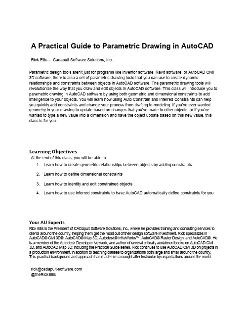
A Practical Guide to Parametric Drawing in AutoCAD Rick Ellis – Cadapult Software Solutions, Inc.Parametric design tools aren’t just for programs like Inventor software, Revit software, or AutoCAD Civil 3D software; there is also a set of parametric drawing tools that you can use to create dynamic relationships and constraints between objects in AutoCAD software. The parametric drawing tools will revolutionize the way that you draw and edit objects in AutoCAD software. This class will introduce you to parametric drawing in AutoCAD software by using both geometric and dimensional constraints to add intelligence to your objects. You will learn how using Auto Constrain and Inferred Constraints can help you quickly add constraints and change your process from drafting to modeling. If you’ve ever wanted geometry in your drawing to update based on changes that you’ve made to other objects, or if you’ve wanted to type a new value into a dimension and have the object update based on this new value, this class is for you.Learning ObjectivesAt the end of this class, you will be able to:1. Learn how to create geometric relationships between objects by adding constraints2. Learn how to define dimensional constraints3. Learn how to identity and edit constrained objects4. Learn how to use inferred constraints to have AutoCAD automatically define constraints for you Your AU ExpertsRick Ellis is the President of CADapult Software Solutions, Inc., where he provides training and consulting services to clients around the country, helping them get the most out of their design software investment. Rick specializes in AutoCAD® Civil 3D®, AutoCAD® Map 3D, Autodesk® InfraWorks™, AutoCAD® Raster Design, and AutoCAD®. He is a member of the Autodesk Developer Network, and author of several critically acclaimed books on AutoCAD Civil3D, and AutoCAD Map 3D; including the Practical Guide series. Rick continues to use AutoCAD Civil 3D on projects in a production environment, in addition to teaching classes to organizations both large and small around the country. This practical background and approach has made him a sought after instructor by organizations around the world.**************************@theRickEllisOverviewWhat is parametric drawing?The Autodesk Definition: “Feature in AutoCAD that assigns constraints to objects, establishing the distance, location, and orientation of objects with respect to other objects.”If the defini tion above didn’t answer all of your questions about parametric drawing, I’ll expand on that and go into a bit more detail. AutoCAD 2010 introduced Parametric drawing. This is not only a relatively new feature for AutoCAD, it is a new concept that will change the way that you create and edit drawings in AutoCAD. While this is a somewhat new feature for AutoCAD, similar tools for parametric design have been in other products like Inventor, Revit, and Civil 3D for some time and you may be familiar with them. Put simply, the idea of parametric drawing is that objects can be related to each other. For example, if you want two lines to be parallel, they would always be parallel. If you change one line then the other will update to match it. This is just one example. However, if you think about all the possibilities, and all the time that you have spent editing drawings to make sure that all the necessary and related changes have been made for a simple change to the design, these tools have the potential to revolutionize the way that you work.AutoCAD uses two types of Parametric Constraints:▪Geometric Constraints∙The Autodesk Definition: “Rules that define the geometric relationships of objects (or points of objects) elements and control how an object can change shape or size.Geometric constraints are coincident, collinear, concentric, equal, fix, horizontal, parallel,perpendicular, tangent, and vertical.”∙Sticky Object Snaps. They maintain the geometric relationship between objects rather than setting it once at the time you use the object snap and then allowing it to change inthe future.∙Add intelligence to your drawings.∙Allow you to think more about modeling and less about drafting.▪Dimensional Constraints∙The Autodesk Definition: “Parametric dimensions tha t control the size, angle, or position of geometry relative to the drawing or other objects. When dimensions are changed, theobject resizes.”∙You can type the value into a dimension and the object updates. It’s the opposite of associative dimensions. With Dimensional Constraints the dimension value drives thegeometry rather than the geometry driving the dimension.∙Can include equations.∙Can even reference other objects. For example, line 1 is twice the length of line 2.Exercise 1 – Working with Existing Constraints1. Open the drawing Widget Assembly complete.dwg from the folder called Completed Assemblyin the dataset.2. Select the block representing the slider on the shaft (identified by callout number 2).3. Move the block.4. Notice the block can only move along the shaft and the arm rotates as it moves.5. Double click the dimension d1 and change the value to 1.56. Notice that changing the value of the dimension moves the block.7. Select and move one of the callouts.8. Notice the entire row of callouts moves together.9. Try moving other pieces of this assembly to see the different constraints in action.10. Open the drawing Parametric - geometric.dwg from the dataset.11. Move and stretch different pieces of the orthographic projection to see how constraints have beenset up within it.Geometric ConstraintsGeometric Constraints maintain the geometric relationship between objects based on basic geometric properties of the entity or entities you apply them to. AutoCAD supports the following geometric constraint types:▪Coincident▪Co-linear▪Tangent▪Perpendicular▪Parallel▪Horizontal (relative to the current UCS X axis)▪Vertical (relative to the current UCS Y axis)▪Concentric▪Equal▪Symmetric▪Smooth▪FixedThe commands to create and manage Geometric Constraints can be found on the Parametric tab of the ribbon.The table below shows the types of objects that can be used to create geometric constraints and their constraint points.Tips when creating geometric constraints:▪When applying constraints between two entities AutoCAD modifies the second entity selected, leaving the first entity unmodified.▪If you convert an object that has constraints to a ployline the constraints are lost.▪If you explode a polyline that has constraints the constraints are lost.▪If you copy an object with constraints the constraints are copied if all the objects involved in the constraint are copied.Constraint BarsConstraint Bars provide a heads-up interface to help you manage geometric constraints in your drawings. Constraint Bars look and behave a lot like transparent floating tool bars, except that each button on a bar represents a single geometric constraint.When you place your cursor over individual constraints on a constraint bar AutoCAD highlights the button, the entity the constraint applies to, and the corresponding button and entity participating in the constraint.When you right-click on a constraint on the constraint bar there are several commands which you can perform on the constraint, including deleting the constraint, hiding the bar, or managing the constraint bar settings.To delete all constraints on an entity use the Delete Constraints command. Ribbon: Parametric tab >> Manage panel >> Delete Constraints.Exercise 2 – Working with Geometric Constraints1. Open the drawing Parametric - geometric.dwg from the dataset.2. Pan to a blank area of the drawing.3. Draw 4 individual lines similar to the graphic below.4. Add Geometric Constraints to make this a dynamic rectangle.a. Use the Coincident, Parallel, and Perpendicular constraints.5. Zoom extents to find the bracket in the drawing as displayed below.6. Add Geometric Constraints to make the bracket hinge at the corner while keeping both sides ofthe part the same size.7. Zoom extents to find the orthographic projection.8. Copy the orthographic projection.9. Remove all the constraints from the orthographic projection.10. Add geometric constraints to the orthographic projection to make it behave as the original.Auto ConstrainIf applying geometric constraints one at a times seems like a tedious task there is an option to let AutoCAD look for objects that can be constrained and add them for you. Auto Constrain examines entities you select and attempts to automatically constrain the geometry based on its current position.You can control the settings for the Auto Constrain command in the Constraint Settings dialog box. Ribbon: Parametric tab >> Geometric panel >> >> Constraint Settings.Here you can select the type(s) of constraints that you want the Auto Constrain command to apply. You can also set Tolerances for distance and angle. These tolerances will determine if constraints are applied and objects are modified when they are “close” to geometrica lly accurate. When used properly this can help clean up a drawing that was created without using object snaps. However, you want to choose your tolerances carefully as it will allow the Auto Constrain command to modify geometry. If you only want the Auto Constrain command to apply constraints where the geometry is perfect and not modify any geometry, set the tolerances to 0.Inferred ConstraintsInferred constraints automatically apply geometric constraints while creating and editing geometric objects, removing the need for you to add constraints later. The Infer Constraints mode works with your object snaps and is enabled with a toggle on the status bar.Once enabled object snaps that are used when creating or editing objects are also used to infer geometric constraints. Objects are not modified by inferred constraints.Exercise 3 – Working with Auto Constrain and Inferred Constraints1. Open the drawing Parametric – Inferred.dwg from the dataset.2. Pan to a blank area of the drawing.3. Draw a rectangle using the rectangle command.4. Use the Auto Constrain command to add constraints.5. Notice what constraints are added.6. Zoom extents to find the bracket in the drawing as displayed below.7. Use the Auto Constrain command to add constraints.8. Notice what constraints are added.9. Turn on Inferred constraints.10. Draw a rectangle using the rectangle command.11. Notice what constraints are added.Dimensional ConstraintsDimensional Constraints constrain objects by allowing you to enter values or formulas. They work similar to associative dimensions, just in reverse. While associative dimensions update the value of the dimension as the object changes, dimensional constraints update the object when the value of the dimension changes. The dimensions drive the geometry rather than the geometry driving the dimensions. Dimensional constraints come in the following types:▪Aligned▪Horizontal▪Vertical▪Radial▪Diameter▪AngularDimensional constraints can constrain the following properties:▪Distances between objects, or between points on objects▪Angles between objects, or between points on objects▪Sizes of arcs and circlesThere two different kinds of dimensional constraints:▪Dynamic∙Maintain the same size regardless of zoom level∙Can easily be turned on or off globally in the drawing∙Display using a fixed, predefined dimension style∙Position the textual information automatically, and provide triangle grips with which you can change the value of a dimensional constraint∙Do not display when the drawing is plotted▪Annotational∙Change their size when zooming in or out∙Display individually with layers∙Display using the current dimension style∙Provide grip capabilities that are similar to those on dimensions∙Display when the drawing is plottedIf you need to control the dimension style of dynamic constraints, or if you need to plot dimensional constraints, use the Properties palette to change dynamic constraints to annotational constraints.The commands to create and manage Dimensional Constraints can be found on the Parametric tab of the ribbon.Tips when creating dimensional constraints:▪When applying dimensional constraints AutoCAD modifies the constrained geometry to satisfy the new constraint.▪If you convert an object that has constraints to a ployline the constraints are lost.▪If you explode a polyline that has constraints the constraints are lost.▪If you copy an object with dimensional constraints the constraints are copied.▪Dimensional constraints can contain equations.The example above contains a rectangle with two basic dimensional constraints.The example above contains a rectangle with two dimensional constraints where the length (d1) is equal to twice the height (d2).You can manage all the values of your dimensional constraints with the Parameters Manager. Ribbon: Parametric tab >> Manage panel >> Parameters Manager.In the Parameters Manager you can edit expressions and even add user defined variables that you can use in expressions.Exercise 4 – Working with Dimensional Constraints1. Open the drawing Parametric - dimensions.dwg from the dataset.2. Zoom to the rectangle.a. It already has geometric constraints.3. Add Dimensional Constraints for the width and length.4. Edit the width to be 3.5. Edit the length to be twice the width by editing the expression.6. Zoom extents to find the bracket in the drawing as displayed below.a. It already has geometric constraints.7. Add a dimensional constraint to control the angle.8. Draw circles at each end of the part.9. Use a concentric geometric constraint to position them10. Add a dimensional constraint that makes them half the outer radius of the part.Constraints in Dynamic BlocksIntroduced in AutoCAD 2005, Dynamic Blocks extend the capabilities of traditional blocks by providing the ability to define custom grips and properties for your blocks which affect the geometry for the block. You create dynamic blocks by combining Block Actions and Block Action Parameters within the block definition. Now you can extend the power of blocks even further by adding geometric and dimensional constraints to your dynamic blocks.When you add geometric and dimensional constraints to dynamic blocks it is best to add them in the block editor using the commands on the Block Editor tab of the Ribbon.A Block Properties table allows you to define and control values for parameters and properties within a block definition. This will become the list of selectable values in the dynamic block.Exercise 5 – Working Constraints in Dynamic Blocks1. Open the drawing Parametric - blocks.dwg from the dataset.2. Open the block editor.a. Ribbon: Insert tab >> Block panel >> Block Editor.b. Name the new block AUParametric.3. Draw a rectangle using the rectangle command starting the lower left corner of the rectangle at0,0.4. Add Geometric Constraints to make this a dynamic rectangle.5. Add Dimensional Constraints for the width and length.6. Edit the width to be 5.7. Edit the length to be twice the width by editing the expression.8. Add a Block Table.a. Place the block table near the origin of the block.b. Placement of the block table does not need to be exact. It will be the location of a grip onthe block that can be used to select standard sizes.9. Enter 1 for the number of grips.10. Click the Add Properties button11. Select the d1 parameter and Click <<OK>>.12. Enter values for d1 as shown above.13. Click <<OK>> when finished.14. Close the block editor and save the changes.15. Insert the block anywhere in your drawing.16. Select the block and notice the available grips.a. You will be able to stretch it in the vertical direction and the rectangle will keep the 2:1ratio of length to width.b. Select the block table grip and you will see the predefined widths.c. Select one of the values and notice how the block resizes.ConclusionParametric drawing in AutoCAD with geometric and dimensional constraints is a powerful set of tools that may drastically change the way that you create and edit drawings. I hope that this introduction to these exciting features has got you thinking about ways that you can apply it to your own drawings and projects.I encourage you to try it out, start small at first, but I am confident that you fill not only find these tools a powerful time saver but also intuitive and easy to learn.。
应用AutoLISP 实现AutoCAD 参数化绘图
应用AutoLISP 实现AutoCAD 参数化绘图作者:王伯黎,等来源:《中小企业管理与科技·上中下旬刊》 2015年第7期王伯黎张兴蓉宜宾职业技术学院四川宜宾644003摘要:通过对AutoLISP 语言特点的研究,探讨了基于AutoLisp 的AutoCAD 参数化绘图程序设计的基本步骤。
以底板参数化绘图为例,详细阐述了应用DCL 创建人机交流对话框,应用AutoLISP 编写参数化绘图程序的具体过程。
实践证明,AutoLISP 语言功能强大,易学易用,是重要的AutoCAD 二次开发工具。
关键词:AutoLISP;DCL;AutoCAD;参数化绘图1 概述AutoCAD 是美国AutoDesk 公司开发的一个交互式绘图软件,它不仅具有强大的绘图、编辑功能,还具有开放的体系结构,允许用户通过内置的AutoLISP 语言实现二次开发。
在CAD的二次开发中,参数化绘图是其中的一项,它可以让设计者自己通过修改设计参数来制作产品零件的模型图形。
参数化绘图已经从传统的模式中摆脱出来,全面的简化了使用者对零件模型的修改过程,从而提高了效率。
2 AutoLISP 语言特点AutoLISP 是一种内嵌式表处理语言,是CAD 开放式体系结构的一种体现,同时也是LISP (List Processor)语言和CAD 相结合的产物。
AutoLISP 语言不仅拥有普通的高级语言所具备的功能,而且还有普通的高级语言所不具备的强大的处理图形的功能。
它最大的好处在于语法简单易懂,易于掌握,可直接调用几乎全部AutoCAD 命令,因此被广泛应用于AutoCAD 二次开发上。
AutoLISP 语言最典型的应用之一就是实现参数化绘图程序设计。
3 参数化绘图设计方案3.1 绘图对象的选择任何机器或部件都是由若干零件按一定的技术要求装配而成。
零件分为标准件和非标准件两大类。
标准件的结构和尺寸都由标准系列确定,通常由专业厂家生产;而非标准件的结构、形状、大小等需要根据它们在机器或部件中的作用进行设计确定,据此画出每个零件的零件图,以便加工制造。
CAD怎么使用参数化绘图
CAD怎么使用参数化绘图
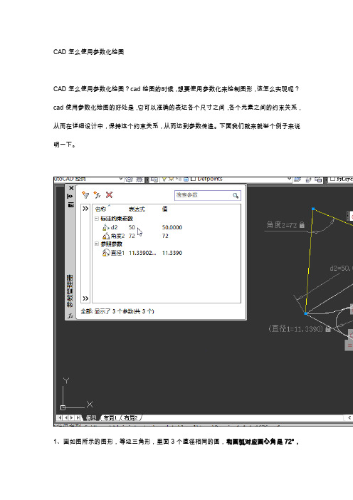
CAD怎么使用参数化绘图?cad绘图的时候,想要使用参数化来绘制图形,该怎么实现呢?cad使用参数化绘图的好处是,它可以准确的表达各个尺寸之间,各个元素之间的约束关系,从而在详细设计中,保持这个约束关系,从而达到参数传递。
下面我们就来就举个例子来说明一下。
1、画如图所示的图形,等边三角形,里面3个直径相同的圆,和圆弧对应圆心角是72°,
他们之间都是相切关系。
尺寸如图,求圆的直径。
2、如果不用参数化,用几何画法,那个需要有丰富几何知识,才能画的出来。
现在用参数化约束他们之间关系,约束标注即可解出。
画任意形状三角形。
3、画如图圆弧
4、画任意三个圆
5、画2条辅助线,调出工具栏
6、快速约束重合关系
7、设定一个参考点
8、约束相等关系
9、约束相切关系
10、约束标注长度
11、约束标注角度
12、修改标注尺寸
13、测量小圆直径
14、从上面画图过程可以清楚的描述他们的关系,可以通过修改尺寸值达到不同的小圆直径,这就参数化的过程,输入值后,我们不关心过程,只要最后的结果,这样,直观快速的得出想要的结果。
以上就是cad参数化绘图的教程,希望大家喜欢
推荐阅读:
CAD制图初学入门/
模具CAD /product/mujucad/ CAD填充/
CAD面积命令/
CAD命令大全/。
CAD参数化绘图实例
CAD参数化绘图实例讲解
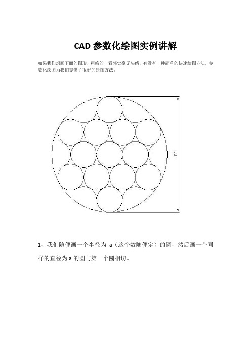
如果我们想画下面的图形,粗略的一看感觉毫无头绪,有没有一种简单的快速绘图方法,参数化绘图为我们提供了很好的绘图方法。
1、我们随便画一个半径为a(这个数随便定)的圆,然后画一个同
样的直径为a的圆与第一个圆相切。
将图形的形状画出来,修剪画出下图
3、利用参照缩放的方式参数化大圆直径
第一点
第二点
缩放---选择对象(全选)---选择基点(圆心)---输入R(参照)---单击大圆上第一点---单击大圆直径上第二点---指定新的长度---输入100
即可。
《AutoCAD》教学指导教案
《AutoCAD》教学指导教案第一章:AutoCAD概述1.1 教学目标让学生了解AutoCAD的基本概念和发展历程。
让学生掌握AutoCAD的基本操作方法和界面组成。
1.2 教学内容AutoCAD的概念和发展历程。
AutoCAD的基本操作方法:打开、保存、关闭文件等。
AutoCAD界面的组成:菜单栏、工具栏、状态栏等。
1.3 教学步骤1. 讲解AutoCAD的概念和发展历程。
2. 演示AutoCAD的基本操作方法。
3. 介绍AutoCAD界面的组成。
1.4 课后作业练习打开、保存、关闭AutoCAD文件。
熟悉AutoCAD界面的组成。
第二章:绘图基础2.1 教学目标让学生掌握AutoCAD的绘图坐标系和绘图单位。
让学生熟悉常用的绘图命令和编辑命令。
2.2 教学内容AutoCAD的绘图坐标系:世界坐标系、用户坐标系。
AutoCAD的绘图单位:毫米、厘米、米等。
常用的绘图命令:Line、Circle、Rectangle等。
常用的编辑命令:Select、Copy、Move、Delete等。
2.3 教学步骤1. 讲解AutoCAD的绘图坐标系和绘图单位。
2. 演示常用的绘图命令和编辑命令。
3. 练习使用绘图命令和编辑命令进行简单的绘图。
2.4 课后作业练习使用Line、Circle、Rectangle等绘图命令。
练习使用Select、Copy、Move、Delete等编辑命令。
第三章:图层和线型3.1 教学目标让学生了解AutoCAD的图层概念和功能。
让学生掌握图层的创建、删除、切换等操作。
让学生熟悉线型的设置和修改。
3.2 教学内容AutoCAD的图层概念和功能。
图层的创建、删除、切换等操作。
线型的设置和修改。
3.3 教学步骤1. 讲解AutoCAD的图层概念和功能。
2. 演示图层的创建、删除、切换等操作。
3. 介绍线型的设置和修改方法。
3.4 课后作业练习创建、删除、切换图层。
设置和修改线型。
第四章:文本和尺寸4.1 教学目标让学生掌握AutoCAD中的文本输入和编辑方法。
三维建模中的参数化草图绘制

三维建模中的参数化草图绘制三维建模中的参数化草图绘制————————————————————————————————作者:————————————————————————————————日期:三维建模中的参数化草图绘制-机械制造论文三维建模中的参数化草图绘制撰文/ 武汉城市职业学院机械工程与电气自动化学院罗光汉参数化草图的绘制是创建各种特征、零件的基础,它贯穿于整个零件的三维建模过程之中。
正确、高效地绘制草图往往对特征、零件的建模起着相当重要的作用。
在草绘过程中运用“形似——添加约束——标注尺寸——修改尺寸”方法实现参数化草图的绘制,能有效地提高草绘的速度与成功率,适用于几乎所有主流的三维CAD 软件。
一、引言草图是根据一定的特征建模要求将一定的设计意图或图样中的直线、圆弧、样条以及文字等图元按照一定的几何与尺寸约束关系绘制在一定的平面上的2D 图形。
参数化草图就是以尺寸参数来控制处于完全约束的草绘截面的大小和形状,这其中涉及了许多先进的设计理念,如“尺寸驱动”、“参数化设计”以及“特征约束”等。
目前,几乎所有三维软件的特征建模与曲面造型中的线框图均不同程度地依赖于草图的绘制。
并且,它们之间具有一定的父子关系。
因此,运用三维CAD软件进行产品、模具等的设计必须重视草图的绘制。
二、参数化草图的绘制采用“形似——添加约束——标注尺寸——修改尺寸”方法,完成参数化草图的绘制能最大限度地减少对图形或图元的编辑操作以节省时间与精力,快速、高效地完成草图的绘制过程,提升软件的应用技能,其具体绘制过程如下。
(1)“形似”就是按照截面图的形状完成近似图形的绘制,必要时可对其中的图元进行适时的拖动,使之看起来“更像”,不必关注系统所添加的任何一个尺寸与约束。
首先,要熟悉所绘制截面图的结构、图元的构成、几何约束与尺寸标注、图元的定位等方面内容,尽可能地掌握图形的大部分结构与主要尺寸,真正做到心中有数。
其次,充分利用现有的参照如系统坐标系或创建合适的定位参照。
参数化绘图在CAD实训改革中的应用
参 数 化绘 图适 用 于结 构 固定 , 寸经 常 改变 的 尺 零 件 图的绘 制 。依据 参数 , 自动生成 图纸 , 使其应 用
次 开发 。
采 ,命 令 脚 本 的优 点 是 形式 直 观 ,可 以使 用 } { j At A uo D中 的所有 绘 图命 令 ,甚 至 图形 编 辑命 令 ; C
其 中有关 计算 机 图形 学 方 面的 问题 完全 交 南 A t u— o C D系 统来 处 理 , A 程序 设 计 简 单 ; 数 绘 图模 块 与 参
将 一 系列 A t A uo D命 令按 顺 序 存 放 在 一 个 文 C 件中 , 称该 文 件为命 令 脚 本 。命 令脚 本 为 A CI文 S I
件, 扩展 名 为 S R。它是 与 A l A C uo D进行 接 口的方 C 式之 一 , 利用 此接 口可 以在 A t AD平 台上进 行 二 uo C
2 1 年 2月 0 1
山西煤 炭管 理干部 学 院学报
J u n l f h n i o lMiigA miit tr olg o r a a x a- nn d nsr o s l e oS C a C e
Fe , 01 b. 2 1
第2 4卷
第 1 期
Vo.4 No 1 12 .
・
科 技纵 横 ・
参数化绘 图在 C D实训改 革中的应用 A
夏 静 文 穆 丽 沙
( . 西煤 炭 职业 技 术 学 院 , 1 山 山两 太 原 0 0 3 ;. 西 省 应用 技 术 学 校 , 30 12山 山西 太 原 0 0 2 ) 3 04
开发AutoCAD实现参数化绘图
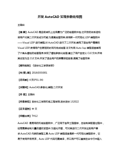
开发AutoCAD实现参数化绘图王晓玲【摘要】AutoCAD是目前微机上应用最为广泛的绘图软件包,它开放的体系结构使用户对其二次开发成为可能.为提高绘图效率,使用新一代可视化LISP编程软件——Visual LISP进行编程,对AutoCAD进行了二次开发,编写了适合用户需要的Visual LISP,使得用户在更短的时间内完成绘图.本文利用Auto lisp 编程语言编写了六角头螺栓的绘图程序,实现了螺栓参数化绘图;建立了用户自定义CUI文件,并将其设定为主CUI文件,开发了适合用户的屏幕按钮菜单,提高了绘图效率.【期刊名称】《吉林化工学院学报》【年(卷),期】2016(033)001【总页数】4页(P31-34)【关键词】AutoCAD;参数化;编程;二次开发【作者】王晓玲【作者单位】吉林化工学院机电工程学院,吉林吉林132022【正文语种】中文【中图分类】TH12AutoCAD是常用的机械绘图软件,广泛用于各种工程图样,在绘制装配图过程中,经常需要绘制大量的螺纹紧固件.为简化作图,可对其进行二次开发达到用户要求.AutoCAD内嵌的编程工具Auto LISP编程语言是新一代可视化编程软件,它易于使用并很灵活,Auto LISP代码无需编译,所以用户可以直接在命令行中输入代码并立即看到结果,使用Auto LISP对AutoCAD进行二次开发,编写适合装配图使用螺纹紧固件绘图程序,实现螺纹紧固件绘图的参数化[1],并利用CUI文件开发屏幕按钮菜单,使用户输入命令方便、快捷.Auto LISP具有许多适合于AutoCAD的专用函数,可以实现Auto LISP程序与AutoCAD绘图命令的结合,使设计与绘图成为一体;还可以通过Auto LISP程序实现对AutoCAD图形数据的直接访问、修改等处理,以便对图形进行绘制、编辑等实时处理,实现图形的交互设计.机械设计人员在绘图装配图过程中,经常需要绘制大量的螺纹紧固件图形,通常情况下,可以通过把标准件制作成图块插入到图形中去,但是当尺寸改变后,块图形就会失去意义.而利用Auto LISP编程语言对AutoCAD进行二次开发,可以编写适用于螺纹紧固件的程序,用户使用时只要把需要的尺寸参数输入进去,就会简单快捷的绘制图形,实现了螺纹紧固件的参数化绘图.1.1 参数设计由于所绘制的图形是添加在其它主体图形上的,所以本螺纹紧固件所有程序的第一个参数为基准点,选择合理的图形基准点,可以使其它参数计算方便、准确,可迅速绘制图形.[2-3]如图1基准点为P0,其余各点的参数关系为:p0p1=2dP2p1=P3p0=0.7dP5p4=l+0.7dP6p0=p9p10=lP7p0=l-2*dP9p7=0.85d/2从而可利用Auto lisp程序方便的计算出其余各点的位置[4].1.2 编写程序1.2.1 编辑程序应用文本编辑软件工具,编写下面的Auto LISP绘图程序[5],启动AutoCAD,点击“工具”下拉式菜单中的“Auto LISP”子菜单“Visual lisp”进入Visual LISP作业环境,新建文件并把编写的Auto LISP绘图程序复制到Visual lisp控制台进行编辑,点击“工具”下拉式菜单中“检查编辑中的文字”进行检测,如图2所示.通过后存储于LJTLS.LSP文件[6].(defun c:ljtls ()(setq p0 (getpoint "确定基点:"))(setq d (getreal"\n 输入螺栓公称直径:"))(setq l (getreal"\n 输入螺栓长度:"))(if( > l (* 2 d)) (princ "ok")(setq l ( * 2 d )))(setq p1 (polar p0 ( * 0.5 pi ) d ))(setq p2 (polar p1 pi ( * 0.7 d )))(setq p3 (polar p0 pi ( * 0.7 d )))(setq p4 (polar p3 (* 0.5 pi ) ( * 0.5 d )))(setq p5 (polar p4 0 ( + l ( * 0.7 d ))))(setq p6 (polar p0 0 l ))(setq p7 (polar p0 0 ( - l ( * 2 d))))(setq p8 (polar p7 ( * 0.5 pi ) ( * 0.5 d ) ))(setq a ( * 0.425 d))(setq p9 (polar p7 ( * 0.5 pi ) a ))(setq p10 (polar p9 0 ( * 2 d )))(Command "line" p0 p1 p2 p3 "" )(Command "line" p4 p5 p6 "" )(Command "line" p7 p8 "" )(Command "line" p9 p10 "" )(command "mirror" "c" p2 p6 "" p0 p6 "n" )(princ))1.2.2 加载程序点击“工具”菜单中的“加载应用程序”,并在控制台提示光标处,输入带有圆括号的Auto LISP程序名,(C:LJTLS),退出Visual LISP作业环境,启动AutoCAD,在命令提示行输入LJTLS命令,并输入基准点、公称直径及公称长度绘出螺栓图形,如图3所示[7].AutoCAD的标准菜单包括文件菜单、编辑菜单、等多个菜单.在以前的版本中,使用基于ASCII的菜单文件(MNU和MNS)来实现菜单的开发.从AutoCAD2006开始,基于MXL的CUI文件取代了以前版本使用的菜单文件,使用户在AutoCAD 中就利用CUI(图形界面开发)的功能,而不再使用曾经的MNU和MNS开发菜单.CUI(自定义用户界面)是一个XML文件,包括主CUI文件、企业CUI文件、局部CUI文件和自定义CUI文件.其中主文件用于定义大部分用户使用的界面,即启动时自动加载的用户界面,企业文件是由CAD管理员管理、对用户是只读文件,局部文件是未加定义的 CUI文件,可随时加载和卸载以满足用户需要.自定义CUI 文件是用户创建的局部CUI文件,它更加容易管理.如果AutoCAD中的标准菜单不包含用户经常使用的命令,用户可根据绘图需要,利用CUI文件对AutoCAD 的标准菜单进行二次开发,通过传输用户可以在原CUI文件上创建自定义CUI文件,可灵活加载和卸载自定义文件,也可将自定义文件设定为主CUI文件[8],下面以六角头螺栓为例:2.1 绘制按钮图像启动AutoCAD,在命令提示行输入“cui”命令,打开用户自定义界面(CUI命令或访问工具》自定义》界面选项,选择“传输”按钮,保存自定义文件,然后选择“自定义”选项卡,在选择自定义命令,点击“新建”按钮,选择“自定义命令”,输入“ljtls”如图5所示.点击“编辑”按钮绘制自定义的按钮图像,并保存在相应的目录下,如图5图片中的螺栓简化图形,建立用户自定义CUI文件[9-10].2.2 创建用户按钮命令选择添加按钮菜单的位置,本文添加位置为绘图下拉式菜单中的多行写文字命令处,并向菜单中添加所需的命令和宏,即在宏输入框中输入用户所需的命令,如图6所示,并存盘确定保存.将其加载为主文件.具体步骤如下:点击“工具”/“选项”/“文件”/“自定义文件”/“主自定义文件”设置主CUI 文件的路径为自定义CUI文件的路径,启动时将自动加载自定义文件.启动AutoCAD,点击自定义CUI文件的“六角头螺栓”图像按钮菜单,如图7所示,输入公称直径、公称长度,在屏幕上指定插入基点,画出六角头螺栓,如图1所示.(1) AutoCAD软件的交互式体统,具有开放的体系结构,提供了丰富的二次开发环境和用户程序接口,用户可根据设计绘图需要,建立数学关系式,利用Auto lisp语言编写参数化绘图程序,建立用户自己的 AutoCAD命令.(2) 通过创建用户CUI自定义文件,实现对屏幕菜单的二次开发,从而实现交互式绘图.(3) 通过输入命令及设计参数实现高效率的工程绘图,减少绘图工作量.【相关文献】[1] 周陶勇,李珊,王磊,等.基于Auto lisp的AutoCAD参数化绘图[J].现代机械,2006,25(4):69-70.[2] 刘俊,朱敏红.基于Auto lisp的AutoCAD程序参数化绘图研究 [J].机械制造及自动化,2010,5(5):112-114.[3] 李鹏.CAD/CAM在板金放样展开及下料方面的应用[J].吉林化工学院学报,2013(3):53-56.[4] 任露泉.试验优化设计与分析[M].北京:高等教育出版社,2003:226-230.[5] 候洪生.机械工程制图[M].北京:科学出版社,2008:360-365[6] 王隆太,朱灯林,戴国洪,等.机械CAD/CAM技术[M].北京:机械工业出版社, 2010:153-158.[7] 蓝屹生.Auto lisp学习指导[M].北京:中国铁道出版社,2003:22-27[8] 郭朝勇.AutoCAD R14(中文版) 二次开发技术[M].北京:清华大学出版社,1999:201-207.[9] 贺炜,李思益.计算机辅助设计[M].北京:机械工业出版社,2004:146-153.[10] 马泽龙.AutoCAD中CUI文件的探讨《2008年全国制造业信息化标准化论坛论文》[C].湖北:武汉大学:2008:89-91.[11] 胡志刚,常丰森.基于Auto lisp齿轮参数化绘图命令的二次开发 [J].河南科技学院学报:自然科学版,2006,42(2):64-69.。
- 1、下载文档前请自行甄别文档内容的完整性,平台不提供额外的编辑、内容补充、找答案等附加服务。
- 2、"仅部分预览"的文档,不可在线预览部分如存在完整性等问题,可反馈申请退款(可完整预览的文档不适用该条件!)。
- 3、如文档侵犯您的权益,请联系客服反馈,我们会尽快为您处理(人工客服工作时间:9:00-18:30)。
7.1 参数化绘图
1、参数化绘图
2、确定参数 3、绘图举例 4、步骤总结 参数化绘图的三个步骤:
第一步:确定图形的基本参数;
第二步:确定和计算绘图参数; 第三步:绘图程序模块的设计与实现。
7.2 形状拼合法绘图
1、图形形状特征
形状相似——结构独立的子图 ——形状特征
7.2 形状拼合法绘图
1、图形形状特征 图形形状特征: 一个工程图可以划分为许多比较简单和 常用的图形部分——子图,这些子图称 为图形形状特征。
7.1 参数化绘图
1、参数化绘图
参数化绘图从本质上讲,就是将图形信息记录 在程序中,因此参数化绘图也可以叫做参数化 编程。 在参数化编程前,要分析图形的拓扑关系、几 何参数以及这些几何参数与图形结构参数之间 的关系。 例如要绘制一个矩形,只要给出矩形的左上角 坐标和矩形的长、宽尺寸,其他的3个矩形顶点 坐标就可以唯 Nhomakorabea地确定。
7.2 形状拼合法绘图
1、图形形状特征 2、绘制传动轴
7.3 参数化设计
1、绘图方法
参数化设计不仅仅是绘图,更 强调的是设计,因此更适合工 程设计的需要。这也是它区别 于参数化绘图的关键。
1)轮廓线法: 用基本图形实体堆砌图形。无约束、通用、绘图繁。 2)参数化绘图: 用少数几个参数描述,整体绘图。绘图速度高;主要用于标 准件、简单图。 3)特征拼图法: 用特征绘图,特征用参数描述。特征设计合理时可显著加速 绘图,但也难以通用。 4)参数化设计法: 工程图是工程设计的反映,设计参数决定了工程图。用设计 参数及其约束来控制并绘制出工程图的方法称为参数化设计。
7.1 参数化绘图
1、参数化绘图
2、确定参数 3、绘图举例 ; 绘图 (command "Line" p1 p2 p0 p3 "") (if (or (and (<= alf1 -90) (>= alf1 - 240)) (and (<= alf1 270) (>= alf1 120)) ) ;end or (setq alf1 (+ alf1 180)) ;选择文本角度 ) ;endif (command "text" "m" p4 h0 alf1 text0) ;以中点方式把p4作为插入点输出文本 );defun结束
7.1 参数化绘图
1、参数化绘图
确定图形的拓扑关系、几何尺寸和结构尺寸的 关系,就可以绘制图形。 图形的结构尺寸和起点坐标信息嵌入在程序中, 只要输入不同的控制参数值,程序就可以生成 具有相似结构和不同尺寸大小的矩形。
7.1 参数化绘图
1、参数化绘图
参数化绘图的优点是程序一旦编制、调 试成功,绘图效率很高。缺点是只能生 成具有相似结构的图形程序。如果要修 改图形的某个部分,需要修改程序。
2)P2点: (setq x2 (+ p0x (* a0 (cos bt2)))) ;x2= p0x + a0 * cos bt2 (setq y2 (+ p0y (* a0 (sin bt2)))) ;y2 =p0y + a0 * sin bt2 (setq p2 (list x2 y2))
3)P3点: (setq x3 (+ p0x (* 2.0 a0 (cos bt1)))) ;x3= p0x + 2. 0 * a0 * cos bt1 (setq y3 (+ p0y (* 2.0 a0 (sin bt1)))) ;y3= p0y + 2.0 * a0 * sin bt1 (setq p3 (list x3 y3)) 4)P4点: (setq x4 (+ p0x (* 1.5 a1 (cos bt4)))) ;x4 = p0x + 1.5 * a1 * cos bt4 (setq y4 (+ p0y (* 1.5 a1 (sin bt4)))) ;y4= p0y + 1.5 * a1 * sin bt4 (setq p4 (list x4 y4))
7.3 参数化设计
1、绘图方法
参数化设计是一种先进的CAD技术,目前比较成熟 的方法主要有:尺寸驱动法和变量设计法两种。 尺寸驱动法就是在现有图形的基础上,通过交互式
2)参数的名称和定义应尽量结合 工程实际。
7.1 参数化绘图
1、参数化绘图
2、确定参数
确定基本参数的原则:
1)对于抽象的几何图形,可以用 尺寸标识作为图形参数。
2)参数的名称和定义应尽量结合 工程实际。
螺钉的外径、滚动 轴承的内径号、齿 轮的模数、齿数、 变位系数等。 3)优先考虑描述零件规格、性能 的参数作为绘图参数。 4)为了便于用户操作,参数的数 量应尽量少。
7.2 形状拼合法绘图
1、图形形状特征 2、绘制传动轴
7.2 形状拼合法绘图
1、图形形状特征 2、绘制传动轴
两个X坐标: a点x0,c点x1; 四个Y坐标: e点y1, d点y2, b点y3, c点y4;
7.2 形状拼合法绘图
1、图形形状特征 2、绘制传动轴 端圆角轴段特征基本参数: 插入点a、圆角半径R、轴径D、轴段长 度W、方位K。 端圆角轴段特征绘图参数: 三线两弧 两个X坐标:a点x0,弧的圆心点x1; 四个Y坐标:下弧圆心点y1, f点y2, b点y3,上弧圆心点y4 过渡圆弧角:起角the1,终角the2
7.1 参数化绘图
1、参数化绘图
2、确定参数 3、绘图举例
(defun c:ccd1() (setq P0 (getpoint "请输入插入点的坐标:")) (setq alf (getangle "请输入旋转角度:")) (setq text0 (getstring "请输入粗糙度的Ra值:")) ;下面计算各绘图参数 (setq h0 (getvar "dimtxt")) ;读取系统变量dimtxt (setq df (getvar "dimscale")) ; 读取系统变量dimscale (setq a0 (* 1.6 h0 df)) (setq a1 (* 1.4 h0 df)) (setq rad (/ pi 170)) ;pi是AutoLISP内部定义的常数,3.1415926 (setq alf1 (/ alf rad)) (setq bt1 (* (+ alf1 60) rad)) (setq bt2 (* (+ alf1 120) rad)) (setq bt4 (* (+ alf1 90) rad)) (setq x1 (+ (car p0) (* a0 (cos bt1)))) (setq y1 (+ (cadr p0) (* a0 (sin bt1)))) (setq p1 (list x1 y1))
7.1 参数化绘图
1、参数化绘图
2、确定参数 3、绘图举例 绘图参数计算: 求四点需三角
(setq bt1 (+ alf1 60)) ;bt1= alf1 + 60 (setq bt2 (+ alf1 120)) ;bt2 = alf1 + 120 (setq bt4 (+ alf1 90)) ;bt4 = alf1 + 90
2)在不影响零件表达的情况下, 图形的某些部分可以采用简化画 法,或使其与某些参数建立一定 关系,从而省去一些参数。 例如,螺栓参数和直径d关联:螺纹内径可近似地等于0.75d, 螺栓头部的曲线用圆弧代替,半径分别为1.5d和0.4d 等。
7.1 参数化绘图
1、参数化绘图
2、确定参数 3、绘图举例
为绘图而设计,通过形状特征拼合来进行绘图可 以降低绘图工作的繁杂性; 划分要合理,既不能过于简单,特征太多;也不 能过于复杂,增加特征程序模块设计的复杂性, 还降低模块的利用率。
7.2 形状拼合法绘图
1、图形形状特征 2、绘制传动轴
7.2 形状拼合法绘图
1、图形形状特征 2、绘制传动轴 倒角特征基本参数: 插入点a、倒角角度theta、轴径D、倒 角宽度B、方位K。 绘图参数: 三条直线 两个X坐标:a点x0,c点x1; 四个Y坐标:e点y1, d点y2, b点y3, c点y4;
7.1 参数化绘图
1、参数化绘图
2、确定参数 3、绘图举例
(setq x2 (+ (car p0) (* a0 (cos bt2)))) (setq y2 (+ (cadr p0) (* a0 (sin bt2)))) (setq p2 (list x2 y2)) (setq x3 (+ (car p0) (* 2.0 a0 (cos bt1)))) (setq y3 (+ (cadr p0) (* 2.0 a0 (sin bt1)))) (setq p3 (list x3 y3)) (setq x4 (+ (car p0) (* 1.5 a1 (cos bt4)))) (setq y4 (+ (cadr p0) (* 1.5 a1 (sin bt4)))) (setq p4 (list x4 y4)) ;下面开始绘图 (command "Line" p1 p2 p0 p3 "") (if (or (and (<= alf1 -90) (>= alf1 -240)) (and (<= alf1 270) (>= alf1 120)) );end or (setq alf1 (+ alf1 180)) );endif (command "text" "m" p4 h0 alf1 text0) ;以中点方式把p4作为插入点输出文本 );defun结束