SYNOPSYS 光学设计软件课程第13课:带有衍射光学元件的激光扩束器
扩束器原理
扩束器原理
扩束器原理是一个光学设备,它可以将光斑的尺寸和强度改变,以便改善检测或成像系统的性能。
扩束器也称作光斑调整器,可以在激光系统或其他光学系统中扮演重要角色。
扩束器是通过使用某种光学元件,如折射镜,透镜,反射镜,棱镜或定向反射器,来实现其功能的。
它可以改变光斑尺寸(诸如宽度,长度和直径),以及它的强度(最大亮度)。
扩束器通常用于改善光学检测或成像系统的性能,如改善聚焦,增强背景分辨率,缩小图像点的尺寸,以及改善实际测量幅度的精度。
它们还可以用于增加光学系统的存储容量,例如一次将更多的信息如图像存储到一个驱动器中,或者在传输光信号时增加数据传输速率。
在光学系统设计中,扩束器有可能不只使用一个,而是多个相互连接。
它们的连接顺序依赖于光学系统的工作原理和功能。
例如,可以将透镜和棱镜结合在一起,以增加光轴的角度,从而在整个系统中改变光斑的尺寸和形状。
其他一些选择包括将多个棱镜组合成一个光学元件,以改变光斑的尺寸或形状,或将透镜和折射镜混合使用,以改变光斑的尺寸和强度。
扩束器的工作原理取决于它的类型和特性。
例如,通过将透镜,折射镜或棱镜组合在一起,它们可以改变光斑的尺寸和强度,从而改善检测或成像系统的性能。
它们也可以用来调整光路中的光斑尺寸和强度,以调整激光输出,改善测量精度,或在传输光信号时增加数据传输速率。
激光放大器PPT课件

n
ntot
{1
1 2[
(
fEp
f
tp 1
) exp( fEp f
fEp tp
tp
f )]}(4.32)
参量 f只与泵浦结构的效率和灯的光谱输出有关。
第13页/共40页
图4.7以泵浦系数f为参
变量,绘出了tp 1ms
时,存储能量与每立方 厘米棒体积上灯的输入 能量的函数关系。
图4.5与图4.7完整的描述了Q开关红宝石放大器的 性能。根据灯的总输入功率和棒体积,可求出参
第6页/共40页
E0
E1
E2
E1
图4.2 单程和双程的单级或多级放大的输出能量密度和提 取效率的计算矩阵形式
如图,它们的关系式为
E1
Es
ln
1
exp
E0 Es
1
exp
g0l
(4.14)
根据式(4.10),提取效率为
1 E1 E0 g0 lE(s 4.15)
第7页/共40页
钕玻璃放大器
在要求以较高的功率和能量来驱动惯性约束聚 变这一目标下,很多实验室开始设计大型钕玻 璃系统。最初这些系统以硅酸玻璃作为钕的基 质材料,后来改用磷酸玻璃。
第16页/共40页
图4.9示出了激光MOPA 系统的原件布局图。在高 峰值功率的激光系统中, 空间滤波片是重要的原件, 它有三种用途:在光束功 率按指数规律增大到高功 率之前,除去光束中的少 量不规则成分;降低光束 空间包络中自聚焦相前畸 变;扩展光束,使光束形 状与不同通光孔的放大器 匹配。
可提取的能量与小信号增益系数之比定义为饱和 能量密度,即
Es hv 21 (4.29)
第11页/共40页
用激光光刻法制备大直径衍射元件

用激光光刻法制备大直径衍射元件
常唯
【期刊名称】《光机电信息》
【年(卷),期】1998(015)010
【摘要】现在,绝大多数光学系统依靠反射或折射元件来实现某些功能。
有资料表明,衍射光学元件(DOE’s)在特定应用中具有某些优点。
有各种制备DOE’s的技术,如金刚石切削技术可以把各种红外材料、金属或塑料制成衍射表面。
还有一种金刚石工具可用来直接在衬底材料上切削出衍射表面的凸凹纹。
金刚石切削一般用在反射金属表面或红外材料(如锗)上。
也有可能用金刚石加工应用于注模塑料法中的母版元件。
金刚石切削技术能制备具有高衍射效率的衍射表面。
用该技术获得最佳衍射效率的关键在于如何将金刚石工具顶端雕刻成所希望的形状。
这一技术的主要缺点是加工工具成本过高。
【总页数】4页(P25-28)
【作者】常唯
【作者单位】无
【正文语种】中文
【中图分类】TH740.6
【相关文献】
1.光纤激光诱导背面干法刻蚀制备二元衍射光学元件 [J], 陈继民;何超;周伟平;申雪飞
2.投影光刻离轴照明用衍射光学元件设计 [J], 张巍;巩岩
3.衍射光学元件在无掩模光刻中的应用 [J], 佟军民;胡松;李爱敏;谢常青
4.基于瑞利-索末菲衍射理论的近场大衍射角衍射光学元件的设计 [J], 李晶;吴鹏;杨正;郑倩颖;李韬杰;向阳;杜春雷;尹韶云
5.用于衍射微光学元件制备的无掩模光刻技术 [J], 陈劲松
因版权原因,仅展示原文概要,查看原文内容请购买。
衍射光学元件在激光雷达光学系统中的应用

衍射光学元件在激光雷达光学系统中的应用
衍射光学元件在激光雷达光学系统中具有重要的应用,主要包括以下几个方面:
1.激光束扩束
在激光雷达系统中,为了增加测距范围和提高激光能量密度,需要将激光束从较小的光斑面积扩展成较大的光斑面积。
这时,可以采用柿子透镜、球面透镜等衍射光学元件对激光进行扩束。
2.光束分束
在激光雷达系统中,为了实现多目标探测,需要将激光束分成多个光束,可以采用衍射光学元件,如光栅、衍射棱镜等对激光进行分束。
3.光束衍射
在激光雷达系统中,为了实现高分辨率探测,需要将激光束衍射成一定的光斑形状。
可以采用衍射光学元件,如宽缝衍射器、光栅等对激光进行衍射。
4.相位调制
在激光雷达系统中,为了实现高精度测量,需要对激光进行相位调制,可以采用衍射光学元件,如相移光栅等对激光进行相位调制。
总之,衍射光学元件在激光雷达光学系统中具有重要的应用,可以对激光进行扩束、分束、衍射、相位调制等,可以提高激光雷达的探测精度和测量范围。
激光扩束镜设计
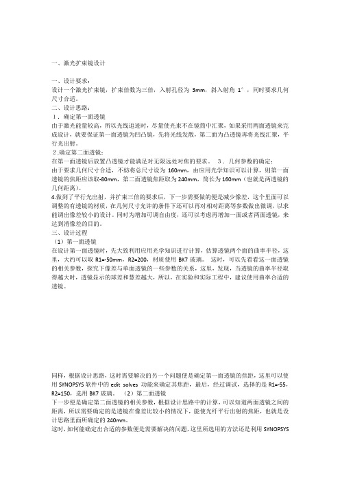
一、激光扩束镜设计一、设计要求:设计一个激光扩束镜,扩束倍数为三倍,入射孔径为3mm,斜入射角1°,同时要求几何尺寸合适。
二、设计思路:1.确定第一面透镜由于激光能量较高,所以光线追迹时,尽量使光束不在镜筒中汇聚,如果采用两面透镜来完成设计,就要保证第一面透镜为凹凸镜,先将光线发散,第二面为凸透镜再将光线汇聚,平行光出射。
2.确定第二面透镜:在第一面透镜后放置凸透镜才能满足对无限远处对焦的要求。
3.几何参数的确定:由于要求几何尺寸合适,不妨将总尺寸设为160mm,由应用光学知识可以计算,则第一面透镜的焦距应该取-80mm,第二面透镜焦距取为240mm,筒长为160mm(也就是两透镜的几何距离)。
4.做到了平行光出射,并扩束三倍的要求后,下一步需要做的便是减少像差,这个里面可以调整的有透镜的材质,在几何尺寸允许的条件下还可以再对相对距离等参数做出微调,以求能调出像差较小的设计。
同时为增加可调自由度,还可以考虑再增加一面或者两面透镜,来达到消像差的目的。
三、设计过程(1)第一面透镜在设计第一面透镜时,先大致利用应用光学知识进行计算,估算透镜两个面的曲率半径,这里,大约可以取R1=-50mm,R2=200,材质使用BK7玻璃。
这时,可以先看看这一面透镜的相关参数,探究下像差与单面透镜的一些参数的关系,这里,发现,当透镜的曲率半径取得越大时,透镜显示的球差和慧差越大,所以,在实验和实际工程中,建议使用曲率合适的透镜。
同样,根据设计思路,这时需要解决的另一个问题便是确定第一面透镜的焦距,这里可以使用SYNOPSYS软件中的edit solves 功能来确定其焦距,最后,经过调试,选择的是R1=-55,R2=150,选用BK7玻璃。
(2)第二面透镜下一步便是确定第二面透镜的相关参数,根据设计思路中的计算,可以知道两面透镜之间的距离,所以需要确定的是透镜在像差比较小的情况下,能使光纤平行出射的焦距,也就是设计思路里面所确定的240mm。
一种激光变焦扩束光学系统设计

一种激光变焦扩束光学系统设计
激光变焦扩束光学系统是一种用于激光束的扩束和变焦的光学系统。
它可以将激光束的直径扩大,并同时调整激光束的焦点位置,以满足不同的应用需求。
在设计激光变焦扩束光学系统时,需要考虑以下几个方面:
1. 扩束倍数:需要根据实际需求确定扩束倍数,一般来说,扩束倍数越高,系统的复杂度和成本也会相应增加。
2. 变焦范围:需要确定系统的变焦范围,以满足不同的应用需求。
3. 光学元件的选择:需要选择合适的光学元件,如透镜、反射镜等,以实现扩束和变焦的功能。
4. 光学设计:需要进行光学设计,以确保系统的光学性能满足要求。
5. 机械结构设计:需要设计合适的机械结构,以支撑和固定光学元件,并实现变焦和调焦的功能。
在设计过程中,可以使用光学设计软件进行模拟和优化,以确保系统的光学性能和机械结构满足要求。
同时,还需要考虑系统的成本和可靠性等因素。
总之,激光变焦扩束光学系统的设计需要综合考虑光学、机械和电子等多个方面的因素,以实现系统的高性能和可靠性。
激光扩束镜结构
激光扩束镜结构激光扩束镜是一种用于调整激光光束直径的光学元件。
它通常由一个具有一定曲率的球面镜面组成。
激光扩束镜结构的设计和制造对于激光器的性能和应用具有重要影响。
一般而言,激光扩束镜由两个主要部分组成:球面镜面和支撑结构。
球面镜面是调整激光光束直径的关键部分,它通常由光学玻璃或光学晶体制成。
球面镜面的曲率决定了光束扩束的方式,不同的曲率可以实现不同的扩束效果。
支撑结构则是用于固定和支撑球面镜面的部分,它通常由金属或塑料材料制成,具有足够的刚度和稳定性。
在激光扩束镜结构中,球面镜面的形状和曲率是关键因素。
一般来说,球面镜面可以分为凸面镜和凹面镜两种类型。
凸面镜具有正的曲率,可以将激光光束聚焦到一个点上,实现光束的收束。
而凹面镜则具有负的曲率,可以将激光光束扩散开来,实现光束的扩束。
根据需要,激光扩束镜可以选择不同曲率的球面镜面来实现不同的扩束效果。
在激光扩束镜结构中,还可以通过调整球面镜面的位置来进一步调整光束的直径。
通过改变球面镜面与光源之间的距离,可以改变光束的扩束或聚束效果。
例如,将球面镜面与光源距离缩小,可以实现光束的扩束;而将球面镜面与光源距离增大,则可以实现光束的聚束。
除了球面镜面和支撑结构,激光扩束镜结构中还可能包括其他辅助部件,如调节装置和冷却系统等。
调节装置可以用于微调球面镜面的位置和角度,以便实现更精确的光束扩束效果。
冷却系统则可以用于控制激光扩束镜的温度,以确保其稳定性和性能。
激光扩束镜结构是由球面镜面和支撑结构组成的光学元件。
通过调整球面镜面的形状、曲率和位置,激光扩束镜可以实现不同的光束扩束效果。
激光扩束镜的设计和制造对于激光器的性能和应用具有重要影响,因此在实际应用中需要根据具体需求进行选择和优化。
Zemax初学者教程(光学设计)习作五:多重结构的激光扩束器
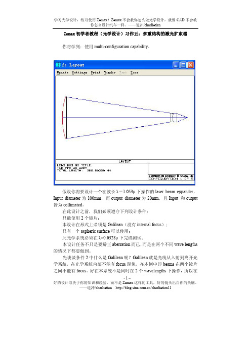
Zemax初学者教程(光学设计)习作五:多重结构的激光扩束器你将学到:使用multi-configuration capability。
假设你需要设计一个在波长λ=1.053μ下操作的laser beam expander,Input diameter为100mm,而output diameter为20mm,且Input 和output 皆为collimated。
在此设计之前,我们必须遵守下列设计条件:只能使用2个镜片;本设计在形式上必须是Galilean(没有internal focus);只有一个aspheric surface可以使用;此光学系统必须在λ=0.6328μ下完成测试;本设计任务不只是要矫正aberration而已,而是在两个不同wave lengths 的情况下都要做到。
先谈谈条件2中什么是Galilean呢?Galilean就是光线从入射到离开光学系统,在光学系统内部不能有focus现象,在本例中即beams在两个镜片之间不能有focus。
好在本系统不是同时在2个wavelengths下操作,所以在- 1 –好的设计取决于你的知识和经验,而不是Zemax这样的工具,好的镜头出自你的头脑。
——道冲/charlietian /charlietian11- 2 –好的设计取决于你的知识和经验,而不是Zemax 这样的工具,好的镜头出自你的头脑。
——道冲/charlietian /charlietian11操作时我们可以变动某些conjugates 。
现在开始设计,依据下图的LDE 表键入各surface 的相关值。
其中surface 5的surface type 从Standard 改为Paraxial ,这时在镜片后面的focal length 项目才会出现。
注意到使用paraxial lens 的目的是把collimated light (平行光)给focus 。
同时把surface 5的thickness 及focal length 皆设为25。
常用激光光学元器件介绍课件

布儒斯特反射镜,反射掉一个方 向的偏振光,透射另一方向偏振光。
偏振分光棱镜,又称PBS,把入 射光分为相互垂直并且偏振方向也相 互垂直的两束光,能量跟入射光的偏 振有关。
第20页/共27页
光栅:对入射光波的振幅或相 位或同时对振幅和相位进行空 间周期性调制的光学元件,具 有分光能力。 整形镜:将高斯分布的光束整 形为其它分布形式的光束。
倍频晶体:一种具有倍频效应 的非线性晶体材料。
第21页/共27页
5、元器件清洁
表面有灰的先用气吹斜着吹 镜头液搭配:酒精+乙醚(1:1) 特别脏的先用丙酮擦拭 往一个方向擦,不可来回擦或绕圈擦 刚粘上指印要马上擦 用灯透射照明检查
第22页/共27页
6、聚焦透镜
EP: enter pupil EFL: effective focal length BFL: back focal length WD: working distance
器件分类
普通元件
全反镜片
分光镜片
扩束镜 聚焦镜 滤光片 保护窗口
偏振元件
波片 布儒斯特镜
起偏器 分光棱镜
其它元件
分光光栅 整形镜片 倍频晶体 激光晶体
第2页/共27页
主要内容
1.光路转折系统 2.聚焦系统 3.保护系统 4.偏振器件及其它 5.元器件清洁 6.聚焦透镜
第3页/共27页
1、光路转折系统
扩束镜可视为倒置望远镜,按扩束原理分为两种 伽利略式、开普勒式
伽利略系统
第9页/共27页
开普勒系统
扩束镜的设计
扩束镜在设计的过程中,是不考虑激光器发散 角的,要求平行光进,平行光出。
第10页/共27页
激光扩束系统设计

光学系统课程设计要求
1、查阅光学设计理论和像差分析的相关文献和资料; 能提出并较好地的实施方案。
2、能用Zemax软件设计简单透镜组,对初级像差进行分 析和校正,从而对激光扩束系统进行优化设计。
3、能对所设计出来的光学系统进行合理的评价,并从工 程角度出发,进行优化设计,最后绘制出工程加工图纸。 4、撰写课程设计论文。要求内容不少于3000字,综述简 练完整、规范、准确;立论正确、论述充分;图表完备、 整洁、正确。 5、报告上交.zmx和.word电子档文件,两个文件打包, 报告名称统一为:姓名+班级+学号
光学系统课程设计内容
设计一个激光光束扩展器(变换器),具体要求如下: 1.输入光束直径为100mm,输出光束直径为20mm 2.使用波长:1064nm 3.测试波长:632.8nm
4.设计须采用伽俐略式(即内部无焦点)
5.只使用两片镜片,只允许使用1个非球面
6.镜片的间隔长度不超过250mm
激光光束扩展器的设计
光学系统课程设计目的 光学系统课程设计内容
光学系统课程设计要求
光学系统课程设计任务安排
光学系统课程设计目的
一、掌握光学系统设计的一般方法和设计思路。
二、掌握简单的、典型的系统设计的基本技能,熟悉光 学设计中所有例行工作,如数据结果处理、像差曲线绘 制、公差分析以及工程图纸绘制等。 三、掌握ZEMAX在光学系统设计中的应用。
光学系统课程设计任务安排
2013.7.1-2013.7.2 布置任务,查找相关的文献,了解激 光扩束系统的基本结构、基本性能要求及相关4 熟悉zemax操作界面,练习输入数据, 评价像质,简单优化。
2013.7.5 根据实例,深入学习Zemax像差控制和优化方法 2013.7.6-2013.7.9 查找专利及镜头库,确定初始结构,选 型,进行优化设计;给出像质评价报告;输出工程加工图 纸 2013.7.10-2013.7.12 撰写课程设计论文,修改定稿并交稿
SYNOPSYS 光学设计软件课程第12课:非球面激光光束整形器

第12课:非球面激光光束整形器在第11课中,我们设计了一个激光束整形器,以平整化小型HeNe激光器的高斯光束轮廓。
为了降低制造成本,我们尝试用球面的设计来达到这个目标,因为它比非球面更容易制造。
使用一个六片透镜设计,这似乎符合我们的规格。
也许这种设计可以进一步改进,但我们也必须要考虑六片球面镜是否比两片非球面镜更便宜。
如果不是,那么非球面设计看起来更具吸引力。
让我们从第11课中使用的相同的双透镜配置开始,进行修改,以便我们只将光通量平坦化为1 / e ** 2点。
得到两倍的孔径似乎是不切实际的,需要需要再次优化。
下面是初始结构文件:RLEID LASER BEAMSHAPER! Beginning of lens input fileWA1 .6328 ! Single wavelengthUNI MM ! Lens is in millimetersOBG .35 1 ! Gaussian object; waist radius -.35 mm; define full aperture at the 1/e**2point.1 TH 22 ! Surface 2 is 22 mm from the waist .2 RD -5 TH 2 GTB S SF6! Guess some reasonable lens parameters; use glass type SF6 from Schott catalog3 UMC 0.3 YMT 5 ! Solve for the curvature of surface 3 so the marginal ray has an angle of0.3; find!spacing so ray height is 5 mm on next surfaceRD 20 TH 4 PIN 2 ! Guesses for surface 4UMC 0 TH 50 ! Solve for curvature of 5 so beam is collimated.7 ! Surfaces 6 and 7 existAFOCAL ! because they are required for AFOCAL output.END ! End of lens input file.由于在第11课中学到了很多,可以用此优化函数开始优化。
八倍激光扩束课程设计

八倍激光扩束课程设计一、教学目标本课程的学习目标包括知识目标、技能目标和情感态度价值观目标。
知识目标要求学生掌握八倍激光扩束的基本原理、方法和应用。
技能目标要求学生能够运用所学知识进行简单的激光扩束实验和数据分析。
情感态度价值观目标培养学生对科学实验的兴趣和好奇心,增强学生的创新意识和团队合作精神。
通过本课程的学习,学生将能够:1.描述八倍激光扩束的基本原理和实验方法。
2.运用所学知识进行简单的激光扩束实验和数据分析。
3.培养对科学实验的兴趣和好奇心,增强创新意识和团队合作精神。
二、教学内容本课程的教学内容主要包括八倍激光扩束的基本原理、实验方法和应用。
教学大纲如下:1.第八章:八倍激光扩束原理1.1 八倍激光扩束的定义和特点1.2 八倍激光扩束的实验方法2.第九章:八倍激光扩束实验2.1 八倍激光扩束实验的步骤和注意事项2.2 八倍激光扩束实验的数据分析3.第十章:八倍激光扩束应用3.1 八倍激光扩束在科学研究中的应用3.2 八倍激光扩束在技术领域的应用三、教学方法本课程的教学方法包括讲授法、讨论法、案例分析法和实验法。
通过多样化教学方法,激发学生的学习兴趣和主动性。
1.讲授法:教师讲解八倍激光扩束的基本原理、实验方法和应用。
2.讨论法:学生分组讨论实验现象和数据,培养团队合作精神。
3.案例分析法:分析八倍激光扩束在科学研究和技术领域的应用案例。
4.实验法:学生动手进行八倍激光扩束实验,提高实验操作能力和科学思维。
四、教学资源本课程的教学资源包括教材、参考书、多媒体资料和实验设备。
1.教材:选用《光学实验教程》作为主要教材,介绍八倍激光扩束的基本原理和实验方法。
2.参考书:推荐《激光原理与应用》、《光学实验指导》等参考书,拓展学生知识面。
3.多媒体资料:制作PPT、实验视频等多媒体资料,辅助教学。
4.实验设备:准备八倍激光扩束实验所需的仪器和设备,如激光器、扩束镜、光具座等。
五、教学评估本课程的教学评估方式包括平时表现、作业和考试。
衍射光学元件设计方法综述

衍射光学元件设计方法综述小伙伴们!今天咱就来好好唠唠衍射光学元件设计方法这事儿。
这玩意儿在光学领域那可是相当重要的,应用超级广泛。
咱可得好好了解了解。
一、衍射光学元件基础。
衍射光学元件,简单来说,就是利用光的衍射现象来实现对光的各种操控的元件。
它和传统的光学元件不太一样哦,传统的像透镜、棱镜啥的,主要是基于光的折射和反射原理。
而衍射光学元件呢,是通过在元件表面制作一些特殊的微结构,让光在传播过程中发生衍射,从而实现像光束整形、分光、聚焦这些功能。
比如说,在一些光学成像系统里,衍射光学元件可以帮助提高成像的分辨率和质量。
还有在光通信领域,它能对光信号进行有效的处理和传输。
那它的设计方法都有哪些呢?接着往下看哈。
二、标量衍射理论设计方法。
这种方法是比较基础和常用的哦。
它主要是基于标量衍射理论,把光看成是标量波来处理。
通过求解标量波动方程,就能得到光在衍射光学元件中的传播规律啦。
在具体设计的时候,一般会先确定设计目标,比如说要实现什么样的光束分布或者光学功能。
然后根据标量衍射理论的公式,计算出元件表面的相位分布。
最后再根据这个相位分布来制作出实际的衍射光学元件。
举个例子哈,如果我们要设计一个能把一束光均匀分布在一个平面上的衍射光学元件,那就可以用标量衍射理论来计算出实现这种均匀分布所需要的相位分布,然后通过光刻或者蚀刻等工艺把这个相位分布制作到元件表面上。
不过呢,标量衍射理论也有它的局限性。
它忽略了光的矢量特性,在一些情况下,比如当光的入射角比较大或者元件的尺寸比较小的时候,计算结果可能就不太准确啦。
三、矢量衍射理论设计方法。
为了克服标量衍射理论的局限性,矢量衍射理论就登场啦。
矢量衍射理论考虑了光的矢量特性,把光看成是矢量波来处理,这样就能更准确地描述光在衍射光学元件中的传播过程。
用矢量衍射理论设计衍射光学元件的时候,计算过程会比较复杂哦。
需要求解麦克斯韦方程组,这可是个有点头疼的事儿。
不过现在有了一些数值计算方法,像有限元法、时域有限差分法这些,就可以帮助我们更方便地进行计算啦。
激光扩束系统设计
光学设计Optical design题目名称:准直扩束系统的设计学校:长春理工大学学院:光电工程学院专业:光电信息工程学号:*********姓名:***2014.01.08目录第一章绪论 (1)1.1引言 (1)1.2激光束及其准直扩束的原理 (1)1.2.1激光高斯光束的特性1.2.2激光束准直扩束的原理1.3折射型扩束器基本结构 (4)1.3.1开普勒扩束镜1.3.2伽利略扩束镜第二章光学设计软件ZEMAX概述 (5)第三章激光准直扩束系统设计 (9)3.1 准直扩束系统的参数确定 (9)3.2确定激光扩束系统的初始结构 (9)3.3 ZEMAX的优化 (11)第一章绪论1.1引言激光扩束系统是激光干涉仪、激光测距仪、激光雷达等诸多仪器设备的重要组成部分,其光学系统多采用通过倒置的望远系统,来实现对激光的扩束,其主要作用是压缩激光束的空间发散角,使扩束后的激光束口径满足其他系统的要求。
激光器发出的光束直径很细小,通常只有零点几到几毫米,激光束的这些特性在某些方面是很有用的。
然而在一些应用领域中需要的确是宽光束,如激光全息、光信息处理、激光照明、激光测距等。
例如在激光干涉仪的应用中,它要照射比激光束口径大得多的被测物体,然后通过光束的干涉来实现测量。
又如在激光的全息应用中,它要照射比激光束口径大得多的全息记录介质,以实现信息的记录和重现。
因此需要使用激光扩束系统来实现激光束的准直扩束。
1.2激光束及其准直扩束的原理1.2.1激光高斯光束的特性激光束的性质是由激光共振腔的几何形状和尺寸决定的,激光束具有特殊的结构,光束呈双曲线形,光束的截面上最小处称束腰(见图2.1),其半径为其中,b为共振腔的共振参数。
共振腔的共焦参数b可由下式求得:其中,R为共振腔球面镜的曲率半径,d为共振腔二镜面之间的距离。
1.2.2激光束准直扩束的原理最通用的扩束镜起源于伽利略望远镜,通常包括一个输入负透镜和一个输出正透镜。
SYNOPSYS 光学设计软件课程十三 带有Kinoform镜头的激光扩束器

在第11课中,您了解了如何使用普通球面透镜设计激光扩束器,并了解到需要多个透镜元件才能获得良好的性能。
第12课采用相同的设计,使用两个非球面元件,效果极佳。
本课程将证明您可以使用DOE(衍射光学元件)。
目标是将腰半径为0.35mm的HeNe激光器转换成直径为10mm且均匀至10%以内的光束。
这是我们初始的输入文件:RLE ! Beginning of lens input file. 。
ID KINOFORM BEAM SHAPERWA1 .6328 ! Single wavelengthUNI MM ! Lens is in millimetersOBG .35 1 ! Gaussian obxxxxject; waist radius -.35 mm; define full aperture = 1/e**2 point.1 TH 22 ! Surface 2 is 22 mm from the waist .2 RD -2 TH 2 GTB S ! Guess some reasonable lens parameters; use glass type SF6 from Schott catalogSF63 TH 20 ! Surface 3 is a kinoform on side 2 of the first element3 USS 16 ! Defined as Unusual Surface Shape 16 (simple DOE)CWAV .6328 ! Zones are defined as one wave phase change at this wavelengtHIN 1.7988 55 ! Assume the zones are machined into the lens. You can also apply ! a film of a different index.RNORM 14 TH 2 GTB SSF64 USS 16CWAV .6328HIN 1.7988 55RNORM 1! The first side of the second element is also a DOE5 CV 0 TH 50 ! Start with a flat surface7 ! Surfaces 6 and 7 existAFOCAL ! because they are required for AFOCAL output.END ! End of lens input file.我们给第2个表面指定了一个合理RD值。
- 1、下载文档前请自行甄别文档内容的完整性,平台不提供额外的编辑、内容补充、找答案等附加服务。
- 2、"仅部分预览"的文档,不可在线预览部分如存在完整性等问题,可反馈申请退款(可完整预览的文档不适用该条件!)。
- 3、如文档侵犯您的权益,请联系客服反馈,我们会尽快为您处理(人工客服工作时间:9:00-18:30)。
第13课. 带有衍射光学元件的激光扩束器在第11课中,您了解了如何使用普通球面透镜设计激光扩束器,并了解到需要多个透镜元件才能获得良好的性能。
第12课采用相同的设计,使用两个非球面元件,效果极佳。
本课程将证明您可以使用DOE(衍射光学元件)。
目标是将腰半径为0.35mm的HeNe激光器转换成直径为10mm且均匀至10%以内的光束这是我们初始的输入文件:RLE ! Beginning of lens input file.。
ID KINOFORM BEAM SHAPERWA1 .6328 ! Single wavelengthUNI MM ! Lens is in millimetersOBG .35 1 ! Gaussian object; waist radius -.35 mm; define full aperture = 1/e**2 point. 1TH 22 ! Surface 2 is 22 mm from the waist .2RD -2 TH 2 GTB S ! Guess some reasonable lens parameters; use glass type SF6 from Schott catalog SF63TH 20 ! Surface 3 is a kinoform on side 2 of the first element3 USS 16 ! Defined as Unusual Surface Shape 16 (simple DOE)CWAV .6328 ! Zones are defined as one wave phase change at this wavelengtHIN 1.7988 55 ! Assume the zones are machined into the lens. You can also apply ! afilm of a different index.RNORM 14 TH 2 GTB S! The first side of the second element is also a DOESF64 USS 16CWAV .6328HIN 1.7988 55RNORM 15 CV 0 TH 50 ! Start with a flat surface7 ! Surfaces 6 and 7 existAFOCAL ! because they are required for AFOCAL output.END ! End of lens input file.我们给第2个表面指定了一个合理RD值。
这是现阶段的系统,还没有DOE的非球面系数:任务是找到能够实现我们两个目标的DOE OPD目标。
首先,让我们将第二个透镜的两边保持为平面。
这是我们认为可以完成工作的优化MACro:PANT ! Start of variable parameter definitions.RDR .001 ! This is a very small beam, so use smaller derivative increments to start with VY2 RADVLIST TH 3 ! Vary the airspaceVY 3 G 26 ! Vary term Y**2,VY 3 G 27 ! Y**4,VY 3 G 28 ! and Y**6VY 4 G 26 ! Do the same at surface 4VY 4 G 27VY 4 G 28ENDAANT ! Start of merit function definitionAECACCLUL 150 1 1 A TOTL ! Prevent the system from growing too largeM 5 1 A P YA 0 0 1 0 5 ! Ask for a beam radius of 5 mm on surface 5M 0 1 A P FLUX 0 0 1 0 6 ! Ask for a flux falloff of zero at several zonesM 0 1 A P FLUX 0 0 .98 0 6M 0 1 A P FLUX 0 0 .97 0 6M 0 1 A P FLUX 0 0 .96 0 6M 0 1 A P FLUX 0 0 .95 0 6M 0 1 A P FLUX 0 0 .94 0 6M 0 1 A P FLUX 0 0 .93 0 6M 0 1 A P FLUX 0 0 .92 0 6M 0 1 A P FLUX 0 0 .91 0 6M 0 1 A P FLUX 0 0 .85 0 6M 0 1 A P FLUX 0 0 .8 0 6M 0 1 A P FLUX 0 0 .7 0 6M 0 1 A P FLUX 0 0 .5 0 6M 0 1 A P FLUX 0 0 .3 0 6GSO 0 .1 10 P ! Control the output ray OPD over an SFAN of 10 rays,GSR 0 100 10 P ! and some transverse aberrations too.END ! End of merit function definition.SNAPSYNO 40这个PANT文件改变了一些通用的G变量,我们在上一课中使用它来改变镜头元件上的一些非球面系数项。
但在这种情况下,表面已经被定义为USS类型16,这是一个简单的DOE表面,因此这些选项改变了定义该形状的系数。
(键入HELP USS以了解您可用的形状以及G系数如何应用于它们。
)我们运行这个宏,镜头看起来很有希望。
所以我们再次运行它然后模拟退火几个周期。
一点也不差。
我们尝试改变一些高阶系数。
我们在两个DOE上添加新系数,最高为G 31,即Y ** 12系数。
重新优化后,镜头看起来大致相同,但评价函数功能下降到3.13E-7。
看起来运行收敛了!现在光通量如何随孔径变化?我们输入命令FLUX 100 P 6并得到一条美丽的曲线,几乎是直的,显示在左下方。
这确实是一个很好的设计。
现在的问题是,有人可以做到吗? 表面4的空间频率是多少? 如果它太高,制造技术可能会遇到麻烦。
我们打开MMA 对话框以选择MAP 命令的输入。
我们选择一个HSFREQ over PUPIL 的图,对象为POINT 0,而raygrid CREC 的网格为7,DIGITAL 输出和PLOT 。
结果显示在镜片边缘,右侧,下方的频率为99.43 c / mm 。
这可以达到10微米/周期,这是可能的,但不容易。
我们可以减少到50 c / mm 吗? 我们将变量5 RAD 添加到变量列表中,并为AANT 文件添加新的像差:M 50 .01 A P HSFREQ 0 0 1 0 4程序现在控制表面4上的频率。
我们重新优化,现在表面5略微凸起,4上的空间频率正好在50 c / mm 。
通量均匀性与以前一样好。
任务完成!我们做得怎么样? 在光束重构之前,运行DPROP 命令,检查曲面3处的轮廓。
这显示了该点处光束的高斯分布。
DPROP P 0 0 3 SURF 3 L RESAMPLE现在在表面上6做同样的事情.基本上完美!DPROP P 0 0 6 SURF 3 L RESAMPLE下面是生成的系统的RLE文件,如果评估它,可以将其复制并粘贴到编辑器中:RLEID KINOFORM BEAM SHAPERFNAME 'L13L1.RLE 'MERIT 0.270980E-05WA1 .6328000WT1 1.00000APS 1AFOCALUNITS MMOBG 0.35000000 1.00000000AIR1CV 0.0000000000000 TH 22.00000000 AIR2RAD -0.8227781050995 TH 2.000000002 N1 1.798817102 CTE 0.810000E-052GTB S 'SF6 '3CV 0.0000000000000 TH 74.00214849 AIR3 USS 16CWAV 0.632800HIN 1.798800 55.000000RNORM 1.000003 XDD 1 0.0000000E+00 0.0000000E+00 0.0000000E+00 0.0000000E+00 0.0000000E+00 3 XDD 2 0.0000000E+00 0.0000000E+00 0.0000000E+00 0.0000000E+00 0.0000000E+00 3 XDD 3 2.6875641E+02 5.7065730E+01 -4.1566734E+01 2.8677115E+01 -1.6241740E+01 3XDD4 4.7211923E+00 0.0000000E+00 0.0000000E+00 0.0000000E+004CV 0.0000000000000 TH 2.000000004 N1 1.798817104 CTE 0.810000E-054 GTB S 'SF6 '4 USS 16CWAV 0.632800HIN 1.798800 55.000000RNORM 1.000004 XDD 1 0.0000000E+00 0.0000000E+00 0.0000000E+00 0.0000000E+00 0.0000000E+00 4 XDD 2 0.0000000E+00 0.0000000E+00 0.0000000E+00 0.0000000E+00 0.0000000E+00 4 XDD 3 5.6803879E+00 -9.1936550E-03 6.0997390E-04 -5.7203063E-05 2.2090382E-06 4XDD 4 -3.5824860E-08 0.0000000E+00 0.0000000E+00 0.0000000E+005RAD -159.6274584523634 TH 50.00000000 AIR6CV 0.0000000000000 TH 0.00000000 AIR7CV 0.0000000000000 TH 0.00000000 AIR END。