搬把式快速接头
快速接头基本知识课堂PPT

7
快速接头的类型
直通快速接头 • 无阀 • 主要用于水,或要求
全速流动的其他应用
8
快速接头的类型
手动快速接头 • 必须手动卸下接头上
的套筒方可连接或断 开螺纹短节。通常需 要两只手。
9
快速接头的类型
快插式快速接头 快插式快速接头用一只 手就可以操作。只需将 螺纹短节推入接头承插, 就可完成连接。要断开 连接,必须手动卸下套 筒才可以取下螺纹短节。
• 货车和非公路应用 • 拖车上的湿管 • 垃圾压缩机 • 路面压碎机 • 工厂 MRO 液压系统 • 钢铁厂 • 油井钻探设备 • 动力输出装置 • 低温工程
18
AG 应用
• 农业设备 • 林业设备 • 移动设备 • 钢厂机器 • 草坪设备 • 联合收割机 • 钻井工具
19
高压应用
• 油田设备 • 水下连接 • 实验台 • 救援设备(救生颚) • 卷边机 • 高压动力装置 • 千斤顶 • 建筑 • 铁路
体、内螺纹管接件和凹管接件等
• 螺纹短节:又名堵头、阀杆、凸形头、
连接件、阳螺纹管接件、探头、阳管接 件等
• 密封件:又名 O 型圈、弹性圈、衬垫、
垫圈
• 球体:接头总成的主要部件 • 阀总成:通常由阀、密封件、弹簧和阀
扣环组成。
3
快速接头基本知识 - 术语(续)
快速接头:又叫快速接头装置、 快速接头、快速连接接头、 快速断开、快速操作接头 和快速接件
10
快速接头基础知识
S.T.A.M.P.:
S
尺寸
T
温度
A
应用
M
介质
P
矿用快速接头标准尺寸
矿用快速接头标准尺寸
矿用快速接头是一种广泛应用于矿山、冶金、石化、造船等行业的连接件,具有速装、拆卸方便、密封可靠、承压力大等特点。
标准化的尺寸可以保证矿用快速接头与其他组件之间的互换性,提高设备的通用性和维修效率。
以下是常见的矿用快速接头标准尺寸:
1. 内螺纹连接型快速接头:尺寸从G1/4'到G2'不等,最大承压力为630bar。
2. 外螺纹连接型快速接头:尺寸从R1/4'到R2'不等,最大承压力为630bar。
3. 法兰连接型快速接头:尺寸从DN6到DN125不等,最大承压力为420bar。
4. 管焊接型快速接头:尺寸从6mm到42mm不等,最大承压力为630bar。
以上是常见的矿用快速接头标准尺寸,不同的尺寸适用于不同的应用场合。
在选择矿用快速接头时,应根据实际需求选择合适的尺寸和材质,以确保设备的安全运行。
- 1 -。
扳把式快速接头标准

扳把式快速接头标准扳把式快速接头是一种常用的管路连接方式,它具有安装简便、拆卸方便、密封性能好等优点,因此在工业领域得到了广泛的应用。
为了确保扳把式快速接头的安全可靠使用,制定了一系列的标准,下面将就扳把式快速接头的标准进行详细介绍。
首先,扳把式快速接头的标准主要包括材料标准、尺寸标准、技术要求标准和检验标准。
材料标准是指扳把式快速接头所使用的材料必须符合国家标准或行业标准,以保证其机械性能和化学性能符合要求。
尺寸标准是指扳把式快速接头的外形尺寸、螺纹尺寸等必须符合相关标准,以保证其能够与其他管路配件进行连接。
技术要求标准是指扳把式快速接头的加工工艺、表面处理等必须符合相关标准,以保证其使用性能和耐久性。
检验标准是指对扳把式快速接头进行检验时所需符合的各项指标和方法,以保证其质量符合要求。
其次,扳把式快速接头的标准还包括安装标准和使用标准。
安装标准是指在安装扳把式快速接头时所需符合的安装方法和要求,以保证其安装牢固、密封可靠。
使用标准是指在使用扳把式快速接头时所需符合的使用方法和注意事项,以保证其正常运行和延长使用寿命。
最后,扳把式快速接头的标准还包括维护标准和保养标准。
维护标准是指对扳把式快速接头进行定期维护时所需符合的方法和要求,以保证其使用性能。
保养标准是指对扳把式快速接头进行定期保养时所需符合的方法和要求,以延长其使用寿命。
总之,扳把式快速接头的标准对于保证其安全可靠使用具有重要意义。
只有严格遵守相关标准,才能够确保扳把式快速接头在工业生产中发挥应有的作用,同时也能够保护相关设备和人员的安全。
因此,各个相关行业都应该加强对扳把式快速接头标准的宣传和执行,以推动整个行业的健康发展。
金属软管——精选推荐

⾦属软管⾦属软管表⽰⽅法产品代号:⼯作压⼒ JR 柔性体类型 W 公称通径接头代号 /接头代号 -产品长度说明:1.⼯作压⼒按实际⼯作压⼒填写,或法兰压⼒等级。
两者不⼀致,法兰压⼒等级单独注明。
单位kg/cm2,即0.1Mpa。
如不注⼯作压⼒,产品出⼚试验压⼒按0.6Mpa进⾏,当⼯作压⼒⼤于30Mpa时,产品出⼚⽓密试验压⼒按30MPa进⾏。
2.两端接头代号相同时,后⼀个可省略。
3.如对波纹管、接头材质有特殊要求,请注明。
4.W表⽰波纹管外⽆⽹套,有钢丝⽹套时不标。
5.如软管⼯作状态为运动状态,请注明。
6.⾮直线安装时,安装距离较短,⽽偏移量较⼤,请与本公司联系。
本公司将单独为您设计安装⽅案。
例:通径为10,⼯作压⼒为16Kg/cm2,如选⽤螺旋形柔性体,两端均为活套螺母,定径球形接头,连接参数为M20×1.5,产品长1800mm,其产品代号为:16JRL10TM10-1800通径为100,⼯作压⼒为16Kg/cm2,如选⽤螺旋形柔性体,⼀端为平焊法兰,⼀端为松套法兰,法兰标准为JB/T81-94和JBT83-94,材质为碳钢,产品长度1800mm,其产品代号为:16JRL100FPJA/FRJA-1800。
波纹柔性体类型L型—螺旋形波纹柔性体波纹管是由不锈钢带经机组⾃动剪裁、卷圆、TIG焊、波纹成形⽽成,所有⼯序在⼀条⽣产线上完成。
L型波纹柔性休具有连续的螺旋波形,⽆需对接焊。
适⽤于静态使⽤和运动量不⼤的场合。
材质:1Cr18Ni9Ti,304☆,316,316L☆如⽆特殊声明,波纹管材质为304 ☆如未注明⼯作压⼒,按0.6Mpa设计H型—螺旋形波纹柔性体波纹管是由不锈钢带经剪裁、卷圆、TIG焊、波纹成形⽽成。
H型波纹柔性休具有连续的环旋波形,柔办性好。
受⼒时不易产⽣扭转应⼒。
适⽤于运动场合和对寿命要求较⾼的场合。
材质:1Cr18Ni9Ti,304☆,316,316L☆如⽆特殊声明,波纹管材质为304☆如未注明⼯作压⼒,按0.6Mpa设计复合型波纹柔性体在L型、H型的基础上,根据⼯作介质和⼯作环境的性质增加内衬,或外加覆盖层。
伊顿快速接头

伊顿快速接头简介伊顿快速接头是一种用于连接和断开流体传输系统的装置。
它具有安装方便、操作简单、耐高压、耐腐蚀等特点,广泛应用于工业领域的管道连接中。
本文将介绍伊顿快速接头的特点、使用方法以及应用领域。
特点伊顿快速接头具有以下特点:1.安装方便:伊顿快速接头采用快速连接设计,只需简单操作即可完成连接和断开。
2.操作简单:用户只需旋转手柄即可实现连接和断开操作,无需额外工具。
3.耐高压:伊顿快速接头能够承受高压流体传输,确保系统稳定运行。
4.耐腐蚀:伊顿快速接头采用耐腐蚀材料制成,能够在恶劣环境下使用。
5.可靠密封:伊顿快速接头具有优异的密封性能,能够有效防止流体泄漏。
使用方法伊顿快速接头的使用方法如下:1.准备工作:将需要连接的管道两端清洁干净,确保没有杂质。
2.连接操作:将伊顿快速接头的连接端插入到管道末端,然后旋转手柄一定角度,直到听到“咔嚓”声,表示连接完成。
3.断开操作:旋转手柄,使其回到初始位置,然后轻轻拉出接头即可断开连接。
4.检查密封性:连接完成后,检查接头周围是否有漏液现象,确保密封性良好。
应用领域伊顿快速接头广泛应用于以下领域:1.工业管道:伊顿快速接头适用于各类工业管道的连接,如化工、石油、制药等行业。
2.液压系统:伊顿快速接头可用于液压系统的连接,如航空、机械等领域。
3.燃油传输:伊顿快速接头广泛应用于燃油传输系统,如燃油加油站、油轮等。
4.供水系统:伊顿快速接头适用于供水系统的连接,如城市给排水管道、灌溉系统等。
总结伊顿快速接头是一种安装方便、操作简单、耐高压、耐腐蚀的管道连接装置。
它在工业领域的管道连接中得到广泛应用,并具备可靠的密封性能和良好的耐腐蚀性能。
伊顿快速接头的使用方法简单,只需几个简单步骤即可完成连接和断开操作。
在各种领域中,伊顿快速接头都发挥着重要的作用,确保管道系统的安全运行。
工业快速接头扭紧方案

工业快速接头扭紧方案一、准备工作。
1. 工具大集合。
首先呢,咱得找个合适的扳手。
这扳手就像一个忠诚的小助手,得大小合适,能紧紧咬住快速接头的螺母才行。
要是扳手太大,就像大脚丫子穿小鞋子,使不上劲儿;要是太小呢,又像小娃娃干重活,根本扭不动。
另外,准备一块干净的抹布。
为啥呢?因为有时候接头上可能有油啊、灰啊之类的脏东西,抹布就可以先把这些“小捣蛋”给擦干净,这样扭的时候手就不容易打滑啦。
2. 检查接头。
在扭紧之前,得好好瞅瞅这个快速接头。
看看它有没有啥明显的损坏,就像检查一个小战士有没有受伤一样。
如果有裂缝或者变形的地方,那可不能直接扭,得先把问题解决了,不然扭紧了也可能会出大问题。
二、扭紧过程。
1. 初步定位。
把快速接头对准要连接的部位,就像给两个小伙伴牵线搭桥一样。
轻轻拧上几圈螺母,先让接头和连接部位有个初步的拥抱,但是不要用太大力气,这个时候就像刚牵手,温柔点就好。
2. 正式扭紧。
拿起我们的扳手,开始正式扭紧啦。
如果是小的快速接头,咱可以用一只手握住扳手的头部,另一只手握住扳手的柄,就像握住剑柄一样,然后稳稳地用力。
扭的时候呢,按照顺时针方向扭,就像时钟指针走的方向一样,可别扭反了哦,不然就像逆行开车,会出乱子的。
要是大一点的快速接头,可能就需要两只手一起用力了。
这时候两只手要配合好,就像两个人一起抬重物一样,力量要均衡。
而且要一点一点地加力,不要一下子就使猛劲,不然可能会把接头给拧坏了。
在扭的过程中,要时不时地停下来检查一下,看看接头有没有歪啊,螺母有没有拧紧啊之类的。
一般来说,当你感觉到用比较大的力气扳手都很难再转动螺母的时候,就差不多扭紧了。
但是也别太贪心,扭得太紧了也可能会损坏接头或者连接的设备,就像把衣服扣子系得太紧会崩开一样。
三、最后的检查。
1. 外观检查。
扭紧之后,再仔细看看整个快速接头。
看看螺母有没有完全贴合在接头上,有没有哪个部位看起来不太对劲,就像给刚刚打扮好的小宝贝再检查一下仪容仪表一样。
快速接头P型安全操作及保养规程
快速接头P型安全操作及保养规程快速接头P型是一种常见的接头设备,广泛应用于工业系统中。
本文将介绍快速接头P型的安全操作和保养规程。
安全操作安装前操作在安装前,需要进行以下步骤:•查看设备是否与使用环境匹配,包括压力、温度等参数。
•检查管路系统是否清洁,避免杂质进入设备。
•检查接口是否有损伤,确保设备能够顺畅安装。
安装操作在安装时,需要进行以下步骤:1.确认好接头方向,和管路连接方式,如直接连接或中间接头等等。
2.在管路连接端涂抹润滑油,以便于安装。
3.插入两个连接端口,并用力推进到底部,确保接头连接紧密。
运行时操作在使用设备时,需要进行以下操作:•确认好用户所需的流量,避免超出承受范围。
•定期检查设备连接是否松动或漏油,并进行紧固和密封处的正确调整。
•避免超载、超压或温度过高,避免设备出现危险。
停机时操作在设备停机时:•关闭管路阀门。
•拆下快速接头P型连接器,并清洗连接器表面并涂抹保护剂。
•储存设备时,需避免接头受到机械伤害,避免接头受潮或阳光直射。
保养规程以下是快速接头P型的保养规程:1.每3-6个月需要进行一次维护和保洁,以及检查连接的紧固性。
2.定期清理接头表面,以确保设备的正常使用。
3.润滑接头、消除锈蚀等措施,避免接头变形或出现损坏。
4.接头存储时间不超过3年。
存储环境温度应在 5-30℃范围,不应受潮、损坏或使用不当等因素所影响。
总结通过上述规程的实施,可以有效的确保快速接头P型的正常工作和长期的使用。
正确的安装、低于承受压力、定期保养等措施的实施,是保证设备工作顺畅的一大重要措施。
快换接头 快速接头

快换接头快速接头----520a8858-715e-11ec-864f-7cb59b590d7d 快换接头快速接头快速更换连接器和周期;快速连接器快换接头产品介绍快换连接器是综合美国、英国、德国、日本等国家的先进技术而设计的。
是一种耐油、耐酸碱、耐高压的新型液压气动管道附件。
广泛应用于钢铁、石油、化工、橡胶、矿山、农业机械、玻璃纤维、纺织、造纸、造船等需要管道快速连接和快速卸载的行业。
该产品可用于金属软管、橡胶软管、尼龙管和塑料管。
具有结构合理、密封性好、互换性好、安装方便、管间装卸快、省工省时等优点,大大降低了员工的劳动强度。
本产品具有自锁安全装置,在高压场合安全可靠。
是国内外液压气动管道流水线生产设备最理想的配件产品,其性能完全可以替代同类进口配件。
快换接头按结构不同分为三大类型:●插入式快换接头●搬把式快换接头●爪型快换接头插入快换接头一、结构特点:插入式快换连接器根据其内部结构可分为三种类型:·双向自封快换接头。
如图1所示·单向自封快换接头。
如图2所示·直通快换接头。
如图3所示1.插入双向自密封快换接头其结构如图1所示,其主要特点是在插轴和插套的内孔内分别设有单向阀。
连接接头时,首先将卡套上的卡套推到最右边,然后将卡套的头部插入卡套的内孔中。
此时,卡套和卡套中的阀芯相互作用,离开各自的锥形阀座,从而打开阀门,连接卡套和卡套的两侧通。
当插轴头部插到底后即可松开卡套,卡套在弹簧力的作用下恢复原位,卡套在恢复原位过程中推动钢球进入插轴上的梯形槽内,并将球固定在梯形槽内,产生自锁作用,使插轴被锁定在插套孔内不至脱落,从而实现快速连接。
同时插轴头部外圆有o型圈实现轴向密封,使内部流体不至向外泄露。
当须使接头的两端脱开时,只需将卡套向右推到底,这时在接头内部阀芯的弹簧力作用下,插轴自动从插套孔中退出,同时阀芯在弹簧的作用下,迅速将阀座口封闭,使接头内部流体不至向外泄露,从而实现快速脱离并保持内部流体不向外泄漏的目的。
工业级推拉式快锁圆形连接器C05系列产品说明书
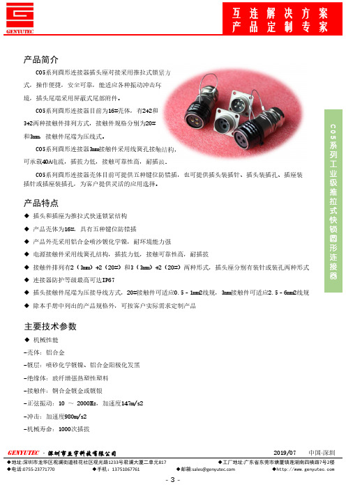
C 05系列工业级推拉式快锁圆形连接器产品简介C05系列圆形连接器插头座对接采用推拉式锁紧方式,操作便捷,安全可靠,能适应各种振动冲击环境,插头尾端采用屏蔽式尾部附件。
C05系列圆形连接器目前为16#壳体,有2+2和3+2两种接触件排列方式,接触件规格分别为20#和3mm,接触件尾端为压线式。
C05系列圆形连接器3mm接触件采用线簧孔接触结构,可承载40A电流,插拔力低,接触可靠性高,耐插拔。
C05系列圆形连接器壳体目前可提供五种键位防错插,也可提供插头装插针、插头装插孔、插座装插针或插座装插孔,为客户提供灵活的应用选择。
产品特点◆插头和插座为推拉式快速锁紧结构◆产品壳体为16#,具有五种键位防错插◆产品外壳采用铝合金喷沙镀化学镍,耐环境能力强◆电源接触件采用线簧孔结构,插拔力低,接触可靠性高,耐插拔◆接触件排列有2(3mm)+2(20#)和3(3mm)+2(20#)两种形式,插头座分别有装针或装孔两种形式◆连接器防护等级最高可达IP67◆插头接触件尾端为压接导线方式,20#接触件可适应0.5–1mm2线规,3mm接触件可适应2.5–6mm2线规◆除本手册中列出的产品规格外,可按客户实际需求定制产品主要技术参数◆机械性能-壳体:铝合金-镀层:喷砂化学镀镍、铝合金阳极化发黑-绝缘体:玻纤增强热塑性塑料-接触件:铜合金镀金或镀银-正弦振动:10 ~2000Hz,加速度147m/s2-冲击:加速度980m/s2-机械寿命:1000次插拔接触件代号插针配合直径(mm)电流(A)接触电阻(mΩ)适配导线规格(mm 2)20#Ø1.027.5200.5/1.0Ø3.0231 4.0Ø3.04016.0◆电气性能-接触件额定电流及接触电阻C 05系列工业级推拉式快锁圆形连接器工作电压400V AC/690V DC耐电压3000V AC-额定工作电压及耐电压(交流有效值)-绝缘电阻:2000MΩ◆环境性能-工作温度:-55 ℃~+125 ℃-相对湿度:温度40±2 ℃时,为90%~95%-防护等级:IP67-温度冲击:-55 ℃ ~+105 ℃,20个循环-盐雾:96h型号命名C05TW16J 04Y DN ①②③④⑤⑥⑦⑧①主称代号②连接器类型:T –插头,Z –插座③键位:X、Y、Z、W、N(N键位不标识)④壳体号:16⑤接触件类型:J –插针,K –插孔⑥接触件数量:04,05⑦接触件端接形式:Y –压接导线⑧镀层:DN –铝合金喷沙镀化学半光亮镍C 05系列工业级推拉式快锁圆形连接器键位号插头插座X:270°Y:315°Z:90°W:45°N:标准防错插键位产品有X、Y、Z、W 、N(N为标准键位)五种键位,实现防错插C 05系列工业级推拉式快锁圆形连接器插头孔位排列及外形尺寸C05T16J05YDNC05T16K05YDNC05T16J04YDNC05T16K04YDNC 05系列工业级推拉式快锁圆形连接器C05Z16K05YDNC05Z16J05YDNC05Z16K04YDNC05Z16J04YDN方法兰插座孔位排列及外形安装尺寸C 05系列工业级推拉式快锁圆形连接器接触件外形尺寸20#插针合件3mm插针合件20#插孔合件3mm插孔合件。
扳把式快速接头执行标准(一)
扳把式快速接头执行标准(一)扳把式快速接头执行标准简介扳把式快速接头是一种用于连接和断开管路的装置,通常用于液压、气动等系统中。
为了确保扳把式快速接头的安全性和可靠性,制定了相关的执行标准。
标准内容扳把式快速接头执行标准主要包括以下内容:1.设计与材料:扳把式快速接头应符合相关设计标准,并采用合适的材料以保证其耐用性和防腐性。
2.尺寸和接头类型:扳把式快速接头应符合相关尺寸标准,并提供不同类型的接头以适应不同管路的连接需求。
3.连接力和密封性:扳把式快速接头的连接时力应符合相关标准,同时具备良好的密封性能。
4.耐压和耐磨性:扳把式快速接头应经受住相关压力测试和摩擦测试,具备足够的耐压和耐磨性能。
5.安全和可靠性:扳把式快速接头应符合相关安全标准,并提供使用说明以确保其正确的使用方式。
应用范围扳把式快速接头执行标准适用于以下行业和领域:1.液压系统:扳把式快速接头常用于液压系统中,用于连接和断开液压管路。
2.气动系统:扳把式快速接头也常用于气动系统中,用于连接和断开气动管路。
3.工业自动化:扳把式快速接头还可在工业自动化领域中使用,例如连接机器人末端执行器等。
结论扳把式快速接头执行标准在液压、气动和工业自动化领域中广泛应用,是确保扳把式快速接头安全和可靠的重要保障。
优缺点扳把式快速接头具有以下优点:1.便捷性:扳把式快速接头连接和断开时非常便捷,无需专业技能即可完成。
2.时间效率:扳把式快速接头节省了连接和断开管路的时间,提高了工作效率。
3.适应性:扳把式快速接头提供了多种材料和尺寸以适应不同管路的需求。
但是,扳把式快速接头也存在一些缺点:1.安全隐患:如果没有正确使用扳把式快速接头,可能会引起安全问题。
2.限制性:扳把式快速接头只适用于一些管路,而对于一些特殊需求可能不适用。
发展前景随着液压、气动和工业自动化行业的快速发展,扳把式快速接头的需求量不断增加。
特别是随着工业自动化的普及,扳把式快速接头将会在更多的自动化生产系统中得到应用。
快速接头结构原理

快速接头结构原理《快速接头结构原理,嘿,原来如此!》嘿,朋友们!今天咱来唠唠这个快速接头结构原理。
说起来啊,这还跟我前几天遇到的一件事儿有关呢。
那天我正好在家捣鼓我的那些小工具,准备修修我那嘎吱嘎吱响的椅子。
我把各种工具都摆了出来,什么扳手啊、螺丝刀啊,满满当当摆了一桌子。
就在我忙活得热火朝天的时候,突然发现有个管子好像松了。
哎呀,这可咋办呢?我正琢磨着怎么把这管子给固定好呢,突然就想到了快速接头。
你们知道吗,这快速接头啊,就像是一个神奇的小玩意儿。
它的原理其实挺简单的,就是通过一些巧妙的设计,能让两个部件快速地连接起来或者分开。
就好比我们平时扣扣子,一按一扣,就完事了。
我仔细观察了一下我手里的快速接头,它有两个部分,一个公头一个母头。
公头就像是个勇敢的小伙子,母头呢就像个温柔的大姑娘,它们俩一相遇,就能紧紧地抱在一起。
哈哈,是不是很形象呀!当公头插进母头的时候,里面的那些小零件就开始发挥作用啦。
它们就像是一群小精灵,相互配合着,把两个部分牢牢地固定在一起。
然后我就开始想啊,这快速接头可真是太方便了。
比如说,我们家里的水管有时候需要连接或者拆卸,要是没有快速接头,那得多麻烦啊。
还得拧来拧去的,说不定还会漏水啥的。
但是有了快速接头,一下子就搞定啦,省时又省力。
再比如说,在一些工厂里,那些机器设备经常需要更换部件或者维修,如果连接部件都很麻烦的话,那得浪费多少时间和精力啊。
但是有了快速接头,就可以快速地进行操作,提高工作效率。
哎呀,我越想越觉得这快速接头真的是个了不起的发明。
它虽然看起来小小的,但是却有着大大的作用。
就像我们生活中的很多小物件一样,平时可能不觉得它们有多重要,但是一旦需要的时候,就会发现它们真的是不可或缺的。
我修好椅子后,看着那快速接头,心里还挺有成就感的。
感觉自己又学到了一个新知识,对这个世界又多了一份了解。
所以啊,朋友们,别小看了这些小小的东西,它们背后可都有着不简单的原理和故事呢。
快速接头

SeriesCAT.0116-GBUNI EN ISO 9001Cert.n°2905ISO/TS 16949CPV-CNV Series• I nterchangeable accordingto ISO 7241-1 part A standards.• Breakaway feature (if panel mounted).• Double action sleeve:Push-Pull connection and disconnection.• Hardened valve bodies to stand crashes.• Wide range of threads and connectors.• Accessories and spare parts kit available with detailed assembling instructions.CVV Series• Screw-on system ensures connection under pressure.• Friction ring to prevent accidental disconnection under heavy vibrations.• Hardened valve bodies to stand crashes.• Interchangeable for the German market.• Wide range of threads and connectors.• Accessories and spare parts kit available with detailed assembling instructions.CPV-CNV Series• Quick-release couplings mainly used in agriculture.• Push-Pull system makes connection and disconnection very easy.• Conformity to ISO 7241-1 part A standards ensures worldwide interchangeability.CVV Series• Quick-release couplings mainly used in applications where connection and disconnection under residual pressure is requested.• Screw-on system ensures the widest contact surface on the connection thread.• Great resistance to pressure peaks, vibrations and loads due to hoses bending.CVV Series• Threaded sleeve for screw connection.• Screw-on system ensures connection under pressure.• Friction ring to prevent accidental disconnection under heavy vibrations.• Interchangeable to German market.• Internal components purposely designed to reduce turbolences and consequent pressure drop.• Rolled surfaces in sealing area to ensure the lowest roughness.• Hardened valve bodies to stand crashes.• Contenitive washer with special seal to reduce risk of extrusion.• Guidevalve with mechanical backstop to prevent partial enclosures of valves due to peaks and reverse flow.• Parts subject to loads and wear are hardened by heat treatment.• NBR seals.• PTFE back-up ring.• Metal shoulder to protect the O-ring seal on female coupling.• Wide range of threads and connectors.• Accessories and spare parts kit available with detailed assembling instructions.2CPV-CNV Series• Double action sleeve:Push-Pull connection and disconnection.• Breakaway feature (if panel mounted).• Interchangeable according to ISO 7241-1 part A standards.• Internal components purposely designed to reduce turbolences and consequent pressure drop.• Rolled surfaces in sealing area to ensure the lowest roughness.• Great number of latching balls.• Hardened valve bodies to stand crashes.• Contenitive washer with special seal to reduce risk of extrusion.• Guidevalve with mechanical backstop to prevent partialenclosures of valves due to peaks and reverse flow.• Parts subject to loads and wear are hardened by heat treatment.• Balls racing area on the male coupling induction hardened.• NBR seals.• PTFE back-up ring.• Metal shoulder to protect the O-ring seal on female coupling.• Wide range of threads and connectors.• Accessories and spare parts kit available with detailed assembling instructions.•Improper use and incorrect maintenance of products with high internal working pressures could causemalfunctioning and damage to persons and machines.Therefore it is necessary to carefully conform to the simple instructions contained in this catalogue.For any further information plea-se contact FASTER ®Technical Department.•Before using a new quick-release coupling, please carefully check all data reported in our catalogues.•Make sure that the coupling is suitable for pressure and flow characteristics requested by the applications.•Lubricate the seals and perform a connect and disconnectoperation in order to check the perfect functioning of the coupling.•Verify that threads fit and that their sealing is correct.•If necessary replace damaged components with FASTER ®original spare parts.•Before any connectionand disconnection carefully clean both male and female parts to prevent dirt inclusions into the circuit and consequent seals damage.When couplings are disconnected,it is recommended to protect them with original FASTER ®plugs.•See available item codes in the ordering chart.•As a further help in defining and selecting the most suitable product for the specificapplication please ask and fill-in with as much information as possible the Product Definition Form (mod.A003) sending it back to Faster Customer Service.•The recommendations stated in this catalogue do notconsider all risk factors in every possible application of FASTER ®couplings.•The final choice of the product is under customer ’s responsibility who has to make the selection according to FASTER ®suggestions.•The customer has to make sure that all requirements of chosen parts are respected, efficiency is maintained and the end user is informed about use and maintenance operations.•FASTER ®and its Distributors are not responsible for damages to persons and machines caused by an improper use and an incorrect maintenance of products.•Increase of products ’technical and functional features is FASTER ®’s policy.For that reason all data in this catalogue are not binding.FASTER ®is entitled to modify the specifications without prior notice.•When connecting anddisconnecting CPV-CNV series,be sure there is no pressure in both halves.• When a disconnection is performed, there could be a residual pressure thatdepending on temperature and position could reach high values.This prevents opening the valve in the male part and, as a consequence, the connection is not possible.• Avoid forcing the coupling valve to decrease residual pressure.• Do not use any sharpened tool which could damage the seals when opening the valves.• In case it is not possible to decrease pressure, use aquick-release coupling specifically designed to stand connection and disconnection under pressure (CVV series, for instance).•All FASTER ®quick-release couplings are designed and produced in conformity with the regulations of Quality Managing System according to UNI EN ISO 9001 and UNI ISO/TS 16949.•They bear the FASTER ®logo to guarantee their origin and reliability.•FASTER ®quick-release couplings are distributed worldwide through a network of highly qualified distributors.•If a FASTER ®quick-release coupling is connected to an equivalent competitor ’s type please check the functionality,the sealing and the resistance to working pressure before using the coupling.FASTER ®cannot assure the performance,quality and connecting tolerances of competitor ’s types.•Malfunctioning or leakages due to the above mentioned cases could cause serious damages to persons and machines.3UNI EN ISO 9001Cert.n °2905ISO/TS 16949N E WCPV-CNV series quick-release couplingsThe descriptions and illustrations in this catalogue are for information only and are not binding.Hardened valve bodiesPTFE back-up ring4M M M M M MM MM M M M M M M M M M M MM M M M M MM M M MM M M MM M M M M M M MM M MM M MM M M MM M M M M M MM MThe descriptions and illustrations in this catalogue are for information only and are not binding.Pressure drop graph :test bench to ISO 7241-2 specifications with ISO VG 32 oil at 40°C (104°F) temperature.Materials :- Female in steel.- Male in high grade carbon steel, induction hardened.- Steel hardened valve.- Surface treatment:zinc plating and Cr III passivation.- Springs in C98 steel.- High resistance balls 100 C6.Seals :Standard in oilproof NBR (Nitrile Rubber).On request:Viton, Neoprene, EPDM or other seals.Antiextrusion rings :In pure PTFE.Working temperatures :with standard seals in NBR (Nitrile Rubber)from -25°C (-13°F) to +125°C (+257°F).For temperature exceeding these values, the quick-release coupling will be supplied with all components in steel together with the appropriate seals.5• Suitable for flexible hoses • Panel mounting by the sleeve• Breakaway feature (if panel mounted)• Versions with lighter sleeve-spring (CNV ...F series page 18)See at pages 15-16-17.*Safety factor = 1:4 - For static pressure safety factor = 1:2Sizemm N lb.l/min.MPa MPa MPa PSI PSI PSI GPM Rated flow Force to connect Max.work pressure Connected MaleFemale Fluid spillage cc.max.Minimum burst pressure06DN Nominal diameter 90.3512026,430435012017400120120174001,1174004010,50810,50.418017,630435012017400120120174002174007519,8163/8”1/2”1”17,50.6926558,3213045851232511011015950131595027071,4inc MPa PSI *❖❖Size GAS = BSP *On requestThe descriptions and illustrations in this catalogue are for information only and are not binding.6Series08❖Size GAS = BSP *On requestThe descriptions and illustrations in this catalogue are for information only and are not binding.7080616SeriesScrew-on couplings CVV seriesM MM M M M M MM M M M M M M M M MM MM MM M M M M MM M MM M M M MM M M MHydrodynamic Wide range of threadsHardened valve bodiesM M MMPTFE back-up ring8The descriptions and illustrations in this catalogue are for information only and are not binding.The descriptions and illustrations in this catalogue are for information only and are not binding.Pressure drop graph :test bench to ISO 7241-2 specifications with ISO VG 32 oil at 40°C (104°F) temperature.Materials :- Female in steel.- Male in high grade carbon steel.- Steel hardened valve.- Surface treatment:zinc plating and Cr III passivation.- Springs in C98 steel.Seals :Standard in oilproof NBR (Nitrile Rubber).On request:Viton, Neoprene, EPDM or other seals.Antiextrusion rings :In pure PTFE.Working temperatures :with standard seals in NBR (Nitrile Rubber)from -25°C (-13°F) to +125°C (+257°F).For temperature exceeding these values, the quick-release coupling will be supplied with all components in steel together with the appropriate seals.9*Safety factor = 1:3 - For static pressure safety factor 1:2MPa MPa PSI PSI PSI work pressure Connected MaleMinimum burst pressure69601602320015021750551014020300114165304930536547851261201401827017400203001021101121479015950162405365110159501101595008 120810❖Size GAS = BSP *On request Continued on page 11Female MaleThe descriptions and illustrations in this catalogue are for information only and are not binding.Series1108❖Size GAS = BSP *On request0816080608Continued on page 12The descriptions and illustrations in this catalogue are for information only and are not binding.SeriesFemmina Maschio120608060808❖Size GAS = BSP *On request Continued on page 13 The descriptions and illustrations in this catalogue are for information only and are not binding.Series13❖Size GAS = BSP *On request0406081624The descriptions and illustrations in this catalogue are for information only and are not binding.Series*Safety factor = 1:3 - For static pressure safety factor = 1:2The descriptions and illustrations in this catalogue are for information only and are not binding.Pressure drop graph :test bench to ISO 7241-2 specifications with ISO VG 32 oil at 40°C (104°F) temperature.Materials :- Female in steel.- Male in high grade carbon steel.- Steel hardened valve.- Surface treatment:zinc plating and Cr III passivation.- Springs in C98 steel.Seals :Standard in oilproof NBR (Nitrile Rubber).On request:Viton, Neoprene, EPDM or other seals.Antiextrusion rings :In pure PTFE.Working temperatures :with standard seals in NBR (Nitrile Rubber) from -25°C (-13°F) to +125°C (+257°F).For temperature exceeding these values, the quick-release coupling will be supplied with all components in steel together with the appropriate seals.CHD mm inc.L mminc.CH mm inc.P mminc.Rd 35x2411,61105,24,14271,06Rd 54x3652,561576,18421,65Rd 54x3652,561576,18421,65Rd 35x2411,61105,24,14271,06Rd 35x2411,61144,25,68271,0636,51,43Rd 54x3652,561716,73--SeriesØD*On requestFemaleMaleFemaleMaleComponents in the kit depend on the coupling size.For information only please refer to background colour of the table.The descriptions and illustrations in this catalogue are for information only and are not binding.TFADust cap for male part TMADust plug for female partTMCVCDust cap for female partTFVVDust plug for male partTMVVDust cap for female partCPV series coupling, female part,green colour.ACCESSORIESThe descriptions and illustrations in this catalogue are for information only and are not binding.TA12This accessory can be applied to the CPV Series PUSH-PULL coupling sleeve for an easier connection and disconnection even by one finger.It is made in Nylon available in different colours.D12Series* On request17SeriesCNV ...FCVF series male coupling equipped with a special threaded sleeve in brass with wing nuts and hexagon shaped interchangeable with CVV Series couplings.In this way manual connection and disconnection are very easy.Those versions can be produced on request in 08-12-16 sizes with the same threaded ends as CVV Series couplings (see at page 9).For further details contact FASTER ®Research & Development Dept.SeriesCVF“Special” SeriesThe descriptions and illustrations in this catalogue are for information only and are not binding.18with residual pressure inside.All FASTER ®quick-release couplings are designed and produced in conformity with the regulations of QualityManaging System according to UNI EN ISO 9001and UNI ISO/TS 16949Standards.They bear the FASTER ®logo to guarantee their origin and reliability.FASTER ®quick-release couplings are distributed worldwide through a network of highly qualified distributors.Ask for our cataloguesCAT. 0113-GB English FF Flat-Face seriesC A T 0116/04/06-G BCAT.0112-GB English Agriculture series CAT.0111-GB English Multifaster series CAT.0110/GB English CAT.0110/F Fran çais General LineCAT. 0116-GB English CPV-CNV and CVV series CAT. 0115-GB English Standard series CAT. 0114-GB English Screw-on couplings series CAT. 0118-GB English RF seriesCAT. 0119-GB English VU seriesCAT. 0117-GB English DF seriesI - FASTER S.p.A.I-26027 RIVOLT A D ’ADDA (CR) Italy - Via L.Ariosto, 7(+39) 0363.377211 - Fax (+39) 0363.377333www.faster.it - faster@faster.it D-BENELUX - FASTER - J ürgen Gamers D-40764 LANGENFELD GER - Ursulaweg, 39(+49) (0) 2173.83924 - Fax (+49) (0) 2173.83925www.faster-germany.de - JGamers@t-online.deUK - FASTER - Richard Bennett GB-T A18 7BY UK19 Beechwood Drive CREWKERNE, Somerset(+44) (0) 1460.77020 - Fax (+44) (0) @F - FASTER - Fran çois DivetF-35200 RENNES - 11, Rue Jean Bras(+33) (0) 2.99.51.44.94Fax (+33) (0) 2.99.51.00.13francois.divet@wanadoo.fr USA - FASTER Inc.MAUMEE, OH 43537-9505 - 6560 Weatherfield, Ct.(+1) 419-868-8197 - (+1) 800-231-2501 - Fax (+1) - eng@UNI EN ISO 9001Cert.n °2905ISO/TS 16949。
快速接头

快速接头快速接头快速接头,是一种不需要工具就能实现管路连通或断开的接头。
快速接头可分为:空气用快速接头、氧气燃料气体用快速接头、气体液体共用快速接头、油压用快速接头、惰性气体用快速接头、冷却水温油用快速接头、半导体快速接头。
目录[隐藏]一、按用途形式可分为1、空气用快速接头2、氧气、燃料气体用快速接头3、气体、液体共用快速接头4、油压用快速接头5、惰性气体用快速接头6、冷却水、温油用快速接头7、半导体快速接头二、按结构形式可分为1、两端开闭式2、两端开放式3、单路开闭式三、快速接头的相关功能介绍四、为什么要用快速接头呢?五、如何选定快速接头?六、快速接头分解图和分解说明一、按用途形式可分为 1、空气用快速接头2、氧气、燃料气体用快速接头3、气体、液体共用快速接头4、油压用快速接头5、惰性气体用快速接头6、冷却水、温油用快速接头7、半导体快速接头二、按结构形式可分为 1、两端开闭式2、两端开放式3、单路开闭式三、快速接头的相关功能介绍四、为什么要用快速接头呢?五、如何选定快速接头?六、快速接头分解图和分解说明[编辑本段]一、按用途形式可分为1、空气用快速接头主要用于空气配管、气动工具配件。
对应其用途,有丰富多样的本体材质、尺寸及安装形状多样。
使用注意事项:注意l 请不要用于流体以外的用途。
l 请不要用于适用流体以外的流体。
l 使用时不要超过最高使用压力。
l 不要在使用温度范围以外使用,防止造成密封材料的变形,易导致形成泄露。
l 不要进行人为的击打、弯曲、拉伸、防止造成破损。
l 不要在混入金属粉或砂尘等地方使用,可以在此处使用,沃尔特快速接头可以在很恶劣的工况下使用,并且保证使用寿命的长久。
l 如附着杂物会造成工作不良或泄漏。
l 请勿拆卸快速接头。
2、氧气、燃料气体用快速接头主要用于通用熔断器配管,具有流量大,耐久性,抗腐蚀性的特点。
主体材质、尺寸以及安装形状丰富多样。
使用注意事项:警告l 流体必须从套筒侧流向插头侧。
快速接头安装方法

快速接头安装方法
快速接头安装方法如下:
1. 准备工具:螺丝刀、扳手、橡胶垫片、布料等。
2. 确定接头的类型:根据需要连接的管道类型和尺寸,选择相应的快速接头。
3. 准备管道:确保管道表面光洁、平整,没有明显的损坏或锈蚀。
4. 安装垫片:将橡胶垫片放在接头的内侧,以防止漏水。
5. 连接管道:将接头两端分别连接到需要连接的管道上,确保紧固螺丝旋紧。
6. 检查漏水:打开水源,检查接头是否漏水,如有漏水,需检查螺丝是否紧固,并加紧螺丝。
7. 清洁工作:清理工作区域,确保无杂物残留。
8. 安全措施:操作时注意安全,避免刮伤或伤到手指。
快速接头快速接头-LEGRIS
3148-31583104310431663136311631883183319931583193316631163189316030913391311833103320LF3100接头的埋入步骤LF3100有两处保持导向的功能设计,可防止埋入时之失误在埋入过程中,保护套件会"O"BSPP 螺纹,带"O"BSPT 螺纹,预履特氟龙涂层塑料本体带尾管直接头,BSPT (即3175-3101C D O D O C 3109-31993148-3158D O D O C 3129-3169C * M3及M5公制螺纹产品均内置O型密封垫圈塑料体可以转动以配合管路方向塑料体可以转动以配合管路方向3129可与3109配合实现近距离安装塑料体可以转动以配合管路方向3108-3198D O D C O 3103-3193C C D O 3121-3131塑料体可以转动以配合管路方向塑料体可以转动以配合管路方向等径管对管三通接头异径管对管三通接头管对管直角接头管对管 "Y" 型接头小转大接头大转小接头多出口 "T" 型五通接头管对管1对4 "Y" 型五通接头管对管2对6 八通接头"十"字型四通接头3106D O D2O D1O 31063104D O D1O D1O D2O 31043102D1O D2O D1O D2O D1O D2O 31403168D1O D2O 31663304D1O D2O D1O D1O D2O D2O D1O D2O 3107310731443306D1O D1O D1O D2O D1O D2O穿板式带卡套接头穿板式带内螺纹接头45°弯接头,BSPT (即PT 45°弯接头,BSPP (即PF 311631393146DO 3136直“Y”型绞接式接头,BSPP(即PF)直螺纹3149“T”型绞接式接头,BSPP(即PF直螺纹)311931133133绞接式接头,BSPT (即PT 绞接式接头,BSPP (即PF 3018C 3118C D O D O C D O D C O C D O DO DO D1O D1O管外径扭力Nm×104<2,5 *10-36<4 *10-38<7 *10-310<11 *10-312<16 *10-3旋转角度:0°到 360°31593112 33203132 332133293189耐磨轴承直接头带单向阀,BSPP (即PF 7984-7994LF3000 系列接头锁紧所需扭力最大值:牙径M5 M7带关闭快速接头Legris 乐可利的带关闭快尾管式带关闭快速接头3160DO D O 3091C 带关闭直接头,BSPP (即3391C D O 7996DO 直接头带单向阀,BSPT (即PT 斜螺纹)及 M5 螺纹D O D O C C 螺纹端进气(红)管端进气(绿)4668M5 R1/8 R1/4 R1/8 7995 7995 7995 7995 04 06 06 08 19 10 13 10 7985 7985 7985 7985 04 06 06 08 7985-7995单向阀单向阀单向阀进气型(7984-7985)排气型(7994-7995)加长型直角接头,BSPP (即带内螺纹直角接头,BSPP "T " 型三通终端接头,BSPP 3158C D O 3101D O 3169C D O 3199D C C C O 3114D O 3192DO 3193C D O 塑料本体可以转动配合管路方向3198C D O 塑料本体可以转动配合管路方向C等径管对管直角接头穿板式接头直角接头、BSPT (即 PT 正 "T " 型三通接头、3175CDO 3106DO 3102DO 3104DO 3166D1O D2O 3116DO 3109CDO 3108CDO 塑料本体可以转动配合管路方向塑料本体可以转动以配合管路方向A10管夹,适用塑料管及LF3000接头接头连接杆释放钮3126DO D1O D2O DO 3122ClipDO 3120D311004 02 3110 04 03 A11。
输送带快速接头剥离的常用方法及维修方法

输送带快速接头剥离的常用方法及维修方法常用方法输送带是一种很常见的物流运输设备,它负责将各种物品从一处运输到另一处。
在输送带的使用过程中,经常需要进行接头剥离,以更换或维修输送带。
下面将介绍一些常用的输送带快速接头剥离方法。
剥离方法一:手动钳子这是一种简单且常用的接头剥离方法。
使用这种方法需要一把钳子,将钳子插入到接头内部,然后用力向外拉扯,直到接头松动为止。
这种方法适用于接头松动度较小的情况。
剥离方法二:液压剪液压剪是一种运用液压系统进行接头剥离的设备。
将液压剪放置于接头上方,然后通过液压系统施加压力,将接头分离。
这种方法适用于接头固定度较大的情况,可以有效降低工作强度。
剥离方法三:接头切割器接头切割器是一种专业的接头剥离设备,它具有切断接头的功能。
将接头切割器放置于接头上方,然后启动机器,机器会自动将接头切断,这种方法适用于接头过于坚固、手动钳子难以剥离的情况。
剥离方法四:氧焊接头使用氧焊进行接头剥离,需要将氧气和乙炔混合,点燃之后将燃气管喷射在接头上,然后等待接头受热断裂。
这种方法不太常用,因为需要专业知识和经验,而且具有一定的危险性。
维修方法输送带除了在剥离接头时需要维修之外,还需要进行一些常规的维修。
下面将介绍一些常用的输送带维修方法。
维修方法一:更换胶带输送带运行一段时间后,胶带可能会磨损或者损坏。
这时就需要更换胶带。
具体方法是先将输送带剥离,然后拆下损坏的胶带,更换新的胶带,再将输送带接头连接好。
维修方法二:调整输送带张力输送带的张力如果过大或过小,都会影响输送带的正常运行。
需要将输送带剥离,然后调整输送带的张力,使其达到适当的程度。
维修方法三:清理输送带输送带在运行过程中可能会受到一些污染,如果不及时清理,这些污染物就会影响输送带的正常运行。
需要将输送带剥离,然后用清洁剂或者清水彻底清理输送带。
维修方法四:校正输送带输送带在长时间的运行中可能会发生偏移,需要进行校正。
具体方法是将输送带剥离,然后使用专业的设备对输送带进行校正。
快速接头使用说明
快速接头使用说明你知道快速接头吧?嗯,不是那种什么“牵个手就能心心相印”的浪漫事儿,而是生活中经常碰到的那种神奇的小工具,平时你也许没怎么注意,但它的作用可大着呢。
简单来说,快速接头就是一种可以迅速连接或断开两条管道、两根电缆的设备,通常我们在一些工业、机械、汽车维修,甚至家里修修水管、接接电线时都能见到它。
别小看它,这玩意儿可真是把我们省心省力的好帮手。
你可能想,嗯,这东西怎么这么神奇?其实它的原理一点都不复杂,换句话说就像是你在开瓶盖时按下去那一刻的爽快感,简单直接,痛快利索!先来个大白话的比喻,你可以把它想象成一对情侣,一旦见面,什么都不用多说,两人就直接融合了。
不管是拧开水管、接上电缆,还是机器里的一堆配件,只要“咔嚓”一下,啪地一声,什么麻烦事就都解决了。
别高兴得太早,想用得顺手,还得明白它的一些注意事项。
哎,这东西也不是随便谁都能轻松玩转的,咱得有点耐心对待。
就像吃辣椒,有的人只要吃上一口就能嗨到爆,而有的人则得从慢慢的适应开始,否则直接喷火的后果你懂得。
讲真,使用快速接头最重要的一点就是“别暴力操作”。
不管是连接水管,还是装配其他的零件,强行扭一扭、使劲一拉,弄不好反而把自己给搞得一团糟。
特别是有些快速接头,它们的材质可是非常讲究的,像金属的、塑料的,硬度、弹性都不一样,随便一用力过猛,接头处可能会出现变形、断裂,那你不白忙活了嘛?所以啊,接头的安装可得讲究“轻轻松松,慢慢来”,稳稳地插进去,感受到那种刚刚合适的卡位,哎呀,这感觉真好,仿佛两颗心终于相通了。
再说说使用时的清洁问题。
嘿,别小看这些小小的接头,时间一长,灰尘、油渍、污垢啥的,就像“沾染上了”。
特别是一些高压环境下的接头,如果长时间不清理,积攒的脏东西多了,可就很容易影响接头的工作效率。
你想,想象一下,如果一个接头跟你脑袋一样,整天也不洗洗,真要出门估计都没人愿意搭理。
对吧?所以,定期的清洁和维护是必须的。
通常你只需要用点儿干净的抹布擦一擦,或者用点清洁剂轻轻喷一喷,这样可以保证接头的灵活性,避免积尘让它卡住、堵塞,甚至影响接头的密封性。
DIN EN 14420-7_搬把式快速接头

DEUTSCHE NORM April 2007DIN EN 14420-7ICS 23.040.70 SupersedesDIN EN 14420-7:2005-05Hose fittings with clamp units-Part 7:Cam locking couplings(includes Amendment A1:2007)English version of DIN EN 14420-7:2007-04Schlaucharmaturen mit Klemmfassungen-Teil 7:Hebelarmkupplungen(enthält Änderung A1:2007)Englische Fassung DIN EN 14420-7:2007-04Document comprises 25 pages © No part of this standard may be reproduced without prior permission of English price group 12DIN Deutsches insitut für Normung e,V.,Berlin Beuth Varlag GmbH,10772 Berlin,Germany, www.din.dehas the exclusive right of sale for German Standards (DIN-Normen). www.beuth.deDIN EN 14420-7:2007-04National forewordThis standard has been prepared by CEN/TC 218 “Rubber and plastics hoses and hose assemblies”(Secretariat:BSI,United Kingdom).The responsible German body involved in its preparation was the Normenausschuss Rohrieitungen und Dampfkesselanlagen(Pipelines and Bo lers Standards Committee),Technical Committee NA 082-00-02 AA SchlauchkupplungenAmendmentsThis standard differs from DIN EN 14420-7:2005-05 as follows:a) The scope has been amended.Previous editionsDIN 2828:1994-02DIN EN 14420-7:2005-05EUROPEAN STANDARD EN 14420-7:2004+A1 NORME EUROPÉENNEEUROPÄISCHENORM january 2007ICS 23.040.70 Supersedes EN 14420-7:2004English VersionHose fittings with clamp units-part 7:Cam locking couplingsRaccords pour flexibles avec demi-coquille-Partie 7: Schlaucharmaturen mit Klemmfassungen-Teil 7: Raccords à cames HebelarmkupplungenThis European Standard was approved by CEN on 30 September 2004 and includes Amendment 1 approved by CEN on 13 December 2006.CEN members are bound to comply with the CEN/CENELEC intermal Regulations which stipulate the conditions for giving this European Standard the status of a national standard without any alteration Up-to-date lists and bibliographical references comcerning such national standards may be obtained on application to the CEN Management Centre or to any CEN member.This European Standard exists in three official versions(English,French,German).A version in any other language made by translation under the responsibility of a CEN member into its own language and notifled to the CEN Management Centre has the same status as the official versions.CEN members are the mational standards bodles of Austria,Belgium, Bulgaria,Cyprus,Czech Republic,Denmard,Estonia,Finland,France,Germany,Greece,Hungary,Iceland,Ireland,Italy,Latvia,Lit huania,Luxembourg,Malta,Netherlands,Norway,Poland,Portugal,Romania,Slovakla,Slovenia,Spain, Sweden,Switzerland and United Kingdom.EUROPEAN COMMITTEE FOR STANDARDIZATIONCOMITÉ EUROPÉEN DE NORMALISATIONEUROPÄISCHES KOMITEE FÜR NORMUNGManagement Centre rue de Stassart,36 B-1050 Brussels© 2007 CEN All rights of exploltation in any from and by any means reserved Ref,No.EN 14420-7:2004+A1:2007:E worldwide for CEN national MembersContentspage Foreword (3)Introduction (4)1 Scope (5)2 Normative references (5)3 Requirements (5)3.1 Construction (5)3.2 Temperatures (6)4 Survey (6)5 Types of connection,survey (8)6 Designation (9)7 Dimensions (9)7.1 General (9)7.2 Coupler types (9)7.3 Cam arm (item No 2) (12)7.4 Pin (item No 3) (13)7.5 Ring (item No 4) (14)7.6 Main gasket (item No 5) (14)7.7 Thread gasket (item No 6) (15)7.8 Adapter types (15)8 Materials (19)8.1 General (19)8.2 Coupler and adapter body (19)8.3 Cam arm (item No 2) (19)8.4 Pin (item No 3) (19)8.5 Ring (item No 4) (19)8.6 Main gasket (item No 5) (19)8.7 Thread gasket (item No 6) (20)9 Marking (20)10 Type approval testing and quality control (20)Annex A (normative) Gauges for cam-locking couplings (21)A.1 Dimensions and designation (21)A.2 Material (22)Bibliography (23)ForewordThis document (EN 14420-7:2004+A1:2007) has been prepared by Technical Committee CEN/TC 218 “Rubber and plastics hoses and hose assemblies”,the secretariat of which is held by BSI.This European Standard shall be given the status of a national standard,either by publication of an identical text or by endorsement,at the latest by July 2007,and conflicting national standards shall be withdrawn at the latest by July 2007.This document includes Amendment 1,approved by CEN on 2006-12-13.The start and finish of text introduced or altered by amendment is indicated in the text by tagsEN 14420 consists at the time of publication of the following parts:EN 14420-1,Hose fittings with clamp units-Part 1:Requirements,survey,designation and testingEN 14420-2,Hose fittings with clamp units-Part 2:Hose side parts of hose tailEN 14420-3,Hose fittings with clamp units-Part 3:Clamp units,bolted or pinnedEN 14420-4,Hose fittings with clamp units-Part 4:Flange connectionsEN 14420-5,Hose fittings with clamp units-Part 5:Threaded connectionsEN 14420-6,Hose fittings with clamp units-Part 6:TW tank truck couplingsEN 14420-7,Hose fittings with clamp units-Part 7:Cam locking couplingsEN 14420-8,Hose fittings with clamp units-Part 8:Symmetrical half coupling (Guillemin system) According to the CEN/CENELEC Internal Regulations,the national standards organizations of the following countries are bound to implement this European Standard: Austria,Belgium, Bulgaria,Cyprus,Czech ,Republic,Denmard,Estonia,Finland,France,Germany,Greece,Hungary,Icelan -d,Ireland,Italy,Latvia,Lithuania,Luxembourg,Malta,Netherlands,Norway,Poland,Portugal,Romania, Slovakla,Slovenia,Spain, Sweden,Switzerland and United Kingdom.IntroductionCam locking couplings are manufactured worldwide according to the American”military specification”MIL-C-27487.This American standard fixes only the coupling side,but not the connection side.Other parts like levers,bolts,ring and seals are not standardized.1 ScopeThis document details the design,materials and dimensions for cam locking couplings that serve as the link between hoses and connections to transport liquids,solids and gases,except liquid gas and steam.The couplings are capable of operating the pressure range -0.8 bar to 16 bar wording pressure in a wording temperature range of -20℃up to +65℃.WARNING—Line pressure shall be reduced before disconnection.2 Normative referencesThe following referenced documents are indispensable for the application of this document.For dated references,only the edition cited applies.For undated references,the latest edition of the referenced document (including any amendments) applies.EN 1982,Copper and copper alloys—Ingots and castingsEN 10083-2,Quenched and tempered steel—Part 1:Technical delivery conditions for unalloyed quality steess (includes amendment A1:1996)EN 10088-1,Stainless steels—Part 1:List of stainless steeslsEN 10213-4,Technical delivery conditions for steel castings for pressure purposes—Part 4:Austenitic and austenitic-ferritic steel gradesEN 10226-1,Pipe threads where pressure tight joints are made on the threads—Part 1:Taper external threads and parallel internal threads – Dinensions,tolerances and designationEN 12420,Copper and copper alloys—ForgingsEN 14420-1,Hose fittings with clamp units-Part 1:Requirements,survey,designation and testingEN 14420-2,Hose fittings with clamp units-Part 2:Hose side parts of hose tailEN 14420-5,Hose fittings with clamp units-Part 5:Threaded connectionsEN ISO 228-1,Pipe threads where pressure-tight joints are not made on the threads–Part 1: Dimensions,tolerances and designation (ISO 228-1:2000)ISO 48,Rubber,vulcanized or thermoplastic–Determination of hardness (hardness between 10 IRHD and 100 IRHD)ISO 272,Fasteners–Hexagon products–Widths across flatsEN 22768-1,General tolerances–Part 1:Tolerances for linear and angular dimensions without individual tolerance indicationsEN 22768-2,General tolerances–Part 2:Geometrical tolerances for fiatures without individual tolerance indications3 Requirements3.1 ConstructionThe curves of the lever and the adapters as well as the dimensions of the sealing ring shall be harmonized such that twisting of the hose and vibrating during operation shall not lead to leakage.Self-acting uncoupling shall be excludedCam arms shall be suitable to operate without using tools.For gauges for cam-locking coupings according to this standard see Annex A.NOTE If the requirements of this standard are met,compatibility between couplers and adapters from different manufacturers is assured.Apart from gaskets the interchangeability between spare parts from different manufacturers cannot be assured.3.2 TemperaturesRange of wording temperatures of couplings equipped with NBR rubber gasket: -20℃ to +65℃.Out of these limits the manufacturer shall be consulted.4 SurveyKeySee Table 1NOTE Chain optionalFigure 1—Coupler type DF and adapter type DP (dust plug)KeySee Table 1NOTE Chain optionalFigure 2—Coupler type DC and adapter type AFTable 1—SurveyItem No. Number of pieces Nomination 1a 1 with internal thread 1b 1 with external thread1c 1 with welding connection1d 1 with hose nipple 1e 1 body cap for coupler 2 2 cam arms 3 2 pin4 2 ring5 1 main gasket6 1 thread gasket for internal thread (see EN 14420-5)7 1 At the discretion of the manufacturer a 8a 1 with internal thread 8b 1 with external thread8c 1 with welding neck8d 1 with hose tail 8e 1 Adapter plug 9 4 ears a The chain is not part of a complete coupling.5 Types of connection,surveyTable 2—Types of connection,surveyCoupler AdapterFigure Type for- detail see Figure Type for-detailseekind of connection DNthreadDF 7.2.1 AF 7.8.1internal thread according to EN ISO 228-1flat-sealed with sealing ring according to EN 14420-52025 32 40 50 65 80 100G 3/4 G1 G11/4 G11/2 G2 G21/2 G3 G4BF a7.2.2FFa7.8.2external threadaccording to EN 10226-120 25 32 40 50 65 80 100R 3/4 R1 R11/4 R11/2 R2 R21/2 R3 R4DW 7.2.3 AW 7.8.3welding connection20 25 32 40 50 65 80 100—CC 7.2.4 EC 7.8.4hose tail20 25 32 40 50 65 80 100—DC 7.2.5 DP 7.8.5dust cap,dustplug20 25 32 40 50 65 80 100—a Prepared for flat face connections.6 DesignationExample for an ordering designation of a complete coupler with nominal size DN 20 with internal thread (DF) made of copper-zinc alloy (CW614N):Coupler EN 14420-7-20-DF- CW614NExample for an ordering designation of a complete adapter with nominal size DN 20 with internal thread (AF) made of copper-zinc alloy (CW614N):Adapter EN 14420-7-20-AF- CW614NExample for an ordering designation of the main gasket pos.No 5with nominal size DN 20 made of nitrile butadiene rubber (NBR):Main gasket EN 14420-7-5-20-NBR7 Dimensions7.1 GeneralDetails,which are not fixed,shall be chosen by the manufacturer suitably.General tolerances shall be according to EN 22768.7.2 Coupler types7.2.1Coupler type (item No 1 a)Key1 d6 Threa according to Table 2Figure 3—Coupler type DFTable 3—Coupler type DFDimensions in millimetresDNd 1±0.1d 2 min.d 3±0.2d 4d 5 H8d 7 +0.20h 1±0.2h 2 0 -0.2h 3 max.l 1 min.l 3 min.l 4 min.m 1 +1 -0m 2 max.b 1 min.S a20 32.4 41 36 18 4 26.5 6.5 3 42.545 8 21 15.2 30.5 12 3225 37.3 47 40.8 24 5.4 33.550 53 9.525 19 3641 32 46 57 51 32 42.558.55941.5145040 54 64 57 3848.566 65 21.843 18 6050 63.8 75 68 48 60.5 475.573 26.3 50 20 70 65 76.5 90 80.7 60 6.376.588.577.512 3325.6 51 22 8580 92.2 106 95.8 76 88.5107.581 53 24 100100 120.3 137 125.2 1008114.57.34.5135.585.516 37 27.556 25 130a This width across flats according to ISO 272 shall be used preferably.7.2.2 Coupler type BF (item No 1 b)Table 4—Coupler type BFDimensions in millimetresOther dimensions and specifications see 7.2.1Figure 4—Coupler type BFDN d 8thread according to EN 10226-1l 5amin. l 6 min.20 R 3/4 16 51 25 R1 21 60 32 R11/469 40 R11/224 71 50 R2 28 8165 R21/2 33 8880 R3 36 93100 R4 42 102a It may be agreed upon shorter external threadlengths for flat sealed connections.In this case thedimensions l 5 min.and l 6 min.are shortenedappropriately.7.2.3 Coupler type DW (item No 1 c)Table 5—Coupler type DWDimensions in millimetresDNd 9min.l 7min.l 8min.l 9min.S 1min.20 26.9 17 50 6 2.3 25 33.7 19 56 32 42.4 67 40 48.3 22696.5 2.6 50 60.3 24 7765 76.1 81.57.5 2.980 88.9 83 83.2 100 114.326 86.5 9 3.6Other dimensions and specifications see 7.2.1a Weld chamfer according to the option of the manu- facturerFigure 5—Coupler type DW7.2.4 Coupler type CC (item No 1 d)Table 6—Coupler type CCDimensions in millimetresDN l 10min.20 76 25 82 32 88 40 90 50 103 65 119.5 80 125 100169.5Other dimensions and specifications see 7.2.11 Hose side part of hose tail:dimensions shall be according to EN 14420-2Figure 6—Coupler type CC7.2.5 Dust cap,Coupler type DC (item No 1 e)Table 7—Dust cap,Coupler type DCDimensions in millimetresDNl11min.S2 min.20 4525 512.432 5740 5950 653.265 68.580 704.0100 74.5 5.6 Other dimensions and specifications see 7.2.1Figure 7—Dust cap,Coupler type DC7.3 Cam arm (item No 2)Other dimensions at manufacturer’s option.Is shall bepossible to couple male and female coupling partsand the lever curve (see area marked with an arrow)shall be equal or decreasing at this area to preservethe eccentricity and prevent from self acting openingof the levers in case of shaking and vibrating opera-tion.Figure 8—Cam armTable 8—Cam armDimensions in millimetresDN d 10min.d 11+0.2l 12min.ThicknessS 3min.20 4.1 40 7.5 25 5.5 46 9.132 40 50 65 46.4 67 1180 1006 8.1 78147.4 Pin (item No 3)During assembly pins shall be headed preferably, Table 9—Pin other kinds of fastening are permitted.Dimensions in millimetresThe pin shall be secure in both ears.DNd 12 H 11l 13min.20 4 20 25 5.4 26 32 40 50 65 6.3 3380 1008 35Figure 9—Pin7.5 Ring (item No 4)Table 10—RingDN d 13 S 4Number of turns min.20 25 25 1.832 40 50 65 33 2.4280 10039 2.6 3Figure 10—Ring7.6Main gasket (item No 5)Table 11—Main gasketDNd 14 d 15 S 520 22 35 5.5 25 27 40 32 35 50 40 41 56 50 51 67 65 60 80 80 76 95 100 102 1246.4 Other forms to be agreed between manufacturer and purchaser.Figure 11—Main gasket7.7 Thread gasket (item No 6)See EN 14420-5.7.8 Adapter types7.8.1 Adapter type AF (item No 8 a)Key1 Thread shall be according to EN 14420-5Number of flats at manufacturer’s discretion .Figure 12—Adapter type AFFigure 12—Adapter type AFDimensions in millimetresDNd 18maxd 190 -0.15d 20±0.1l 14l 15min.l 160 -0.15r 10.15 0r 20 -0.4b 2min.S amin.20 21.5 26.3 32.1 2.4 25.4 11.961.6 10 32 25 24.2 29.1 36.7 33.3 14.35 9.452.4 16 4132 28.2 35.3 45.5 39.617.5 5040 36.5 42.9 53.4 41.217.5321.5 6050 46 52.5 63 3.247.5 23.5 7065 56.6 64.6 75.8 49.2 21.5411.0526 8580 73.3 81.3 91.54.8 50.8 100100 98.2 109.4 119.5 5.6 52.3 22.73 12.62 3.2 28130 a See Table 3.7.8.2 Adapter type FF (item No 8 b)Table 13—Adapter type FFDimensions in millimetresl18DNmin.20 51.525 62.532 7740 78.550 88.565 99.580 104100 117.5d8,l5 see 7.2.2Figure 13—Adapter type FFOther dimensions and specifications see 7.8.1 7.8.3 Adapter type AW (item No 8 c)Table 14—Adapter type AWDimensions in millimetresl19DNmin.20 35.525 43.532 5040 51.550 57.565 59.580 60100 62.6 d9,l9,S1 see 7.2.3Other dimensions and specifications see 7.8.1 Weld chamfer according to the option of the manu-facturerFigure 14—Adapter type AW7.8.4 Adapter type EC (item No 8 d)Table 15—Adapter type ECl20DNmin.20 68.525 76.532 8340 84.550 97.565 113.580 119100 161.5 Key Other dimensions and specifications see 7.8.1a Hose side part of hose tail:dimensionsshall be according to EN 14420-2Figure 15—Adapter type EC7.8.5 Dust plug,Adapter type DP (item No 8 e)Table 16—Dust plug,Adapter type DPl21DNmin.20 3725 4532 5240 5350 5965 6280 64100 66 S2 see 7.2.5Other dimensions and specifications see 7.8.1 Figure 16—Dust plug,Adapter type DP8 Materials8.1 GeneralParts shall be manufactured from the materials specified below.If nothing else agreed upon,the manufacturer takes a suitable choice from the listed materials.Whatever the kind of manufacturing procedure is,the minimum mechanical characteristics shall be equivalent to the mechanical characteristics of investment castion (in case of stainless steel) using the materials specified in this standard.8.2 Coupler and adapter bodyCouplers and adapter bodies shall be made of the following materials:copper-zinc alloyCuZn39PB3 material number CW614N in material condition H080 according to EN 12420 CuZn40PB2 material number CW617N in material condition H080 according to EN 12420 GK-CuZn37Pb material number 2.0340.02 according to EN 1982orstainless steelX2CrNIMo17-12-2 material number 1.4404 according to EN 10088-1X5CrNIMo17-12-2 material number 1.4401 according to EN 10088-1X6CrNIMoTi17-12-2 material number 1.4571 according to EN 10088-1GX5CrNIMoNb19-11-2 material number 1.4581 according to EN 10213-4GX5CrNIMo19-11-2 material number 1.4408 according to EN 10213-4X2CrNIMoN25-7-4 material number 1.4410 according to EN 10088-1orCopper tin alloyCuSn5Zn5Pb5 material number CC491K according to EN 19828.3 Cam arm (item No 2)Cam arm shall be made of the following materials:X2CrNIMo17-12-2 material number 1.4404 according to EN 10088-1X5CrNIMo17-12-2 material number 1.4401 according to EN 10088-1X2CrNIMoN25-7-4 material number 1.4410 according to EN 10088-18.4 Pin (item No 3)Pins shall be made of the following materials:X2CrNIMo17-12-2 material number 1.4404 according to EN 10088-18.5 Ring (item No 4)Rings shall be made of the following materials:X10CrNi18-8 material number 1.4310 according to EN 10088-18.6 Main gasket (item No 5)Main gaskets shall be made of the following materials:Nitrile butadiene rubber (NBR) gasket and flat-sealedNitrile butadiene rubber (NBR),IRHD hardness 60±5 according to ISO 48Fluor rubber (FPM) (e.g.Viton) or CSM (e.g.Hypalon) or PTFE encapsulated,IRHD hardness 70±5 according to ISO 48.The gasket selected shall be suitable to resist the product conveyed.Use non-asbestos materials for gaskets.8.7 Thread gasket (item No 6)Thread gaskets shall be made of the following materials:Polyurethane (PUR),hydrolytically stable,IRHD hardness 90±0.5 according to ISO 48 Polytetrafluoroethylene (PTFE)Nitrile butadiene rubber (NBR)Fluor rubber (FPM)Ethylene propylene rubber/plastics (EPDM)The gasket selected shall be suitable to resist the product conveyed.9 MarkingBodies and male parts of the cam locking coupling shall be durably marked on the outside as follwos: — EN 14420-7;—name of manufacturer or trademark;—type and nominal size DN;— material number.10 Type approval testing and quality controlShall be according to EN 14420-1.Annex A(normative)Gauges for cam-locking couplingA.1 Dimensions and designationDetails not specified in this standard are to be chosen as appropriate.Only the dimensions given in Table A.1 shall be complied with.Tolerances shall be according to EN 22768-1 and EN 22768-2.DN 20 to DN 100Figure A.1—Gauge A1Designation of a gauge A1 for a cam coupling with nominal size DN 50:Gauge EN 14420-7—A1—50Table A.1—DimensionsDimensions in millimetresDNd1±0.2d2±0.01d3±0.01d4±0.2l1±0.2l2-0.01l3±0.2r1±0.01r2±0.1b1±0.220 —26.2932.11 14 2.4 11.9645 9.45 1.6 12 25 —29.0636.73 41 3.2 14.3545 9.45 2.4 12 32 —35.2645.52 50 3.2 17.5351 11.05 3.2 12 40 —42.9353.47 60 3.2 17.5355 11.05 3.21350 —52.4563.09 66 3.2 21.5457 11.05 3.21465 —64.6475.82 77 4.8 21.5457 11.05 3.21480 —81.3391.54 102 4.8 22.7364 12.62 3.214100 55 109.4119.58 128 5.6 22.7364 12.62 3.214A.2 MaterialGauge body: Material number 1.0601—Symbol C 60,or equivalent in mechanical resistance according to EN 10083-2.Heat treated and surface protected.Bolt: At the discretion of the manufacturer.Bibliography[1] EN 10204,Metallic products—Type of inspection documents[2] EN ISO 4957,Tool steels (ISO 4957:1999)[3] EN ISO 6708,Pipework components—Definition and selection of DN(nominal size)(ISO 6708:1995)[4] EN ISO 8330,Rubber and plastics hoses and hose assemblies—Vocabulary (ISO 8330:1998)。
操作方便的快速接头卡兰!

快速接头卡兰
快速接头卡兰
谢谢观看
山东亿ቤተ መጻሕፍቲ ባይዱ 快速接头卡兰
快速接头卡兰
kate004
CONTENTS
1 快速接头卡兰介绍
2 快速接头卡兰优势
快速接头卡兰介绍
• 快速接头卡兰主要是用于管道发生破裂破损时的连接,可焊接的,既省时又省力。使用时 卸下两端的螺丝,把两节管子的一端分别焊接在接头套筒上,然后密封上,卡住再上螺丝 即可。
快速接头卡兰优势
• 快速接头卡兰使用时不要超过高使用的承重。 不要用于快速接头以外的用途。在加压状态 下或残压状态下请不要进行连接分离。
