克朗斯安全模块ASI safety master
AES 1265 防护门监控器和应急停止安全控制模块说明书
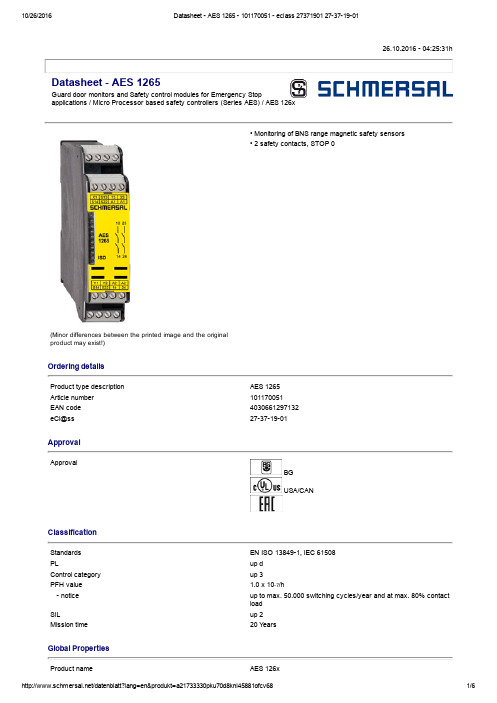
26.10.2016 04:25:31hDatasheet AES 1265Guard door monitors and Safety control modules for Emergency Stopapplications / Micro Processor based safety controllers (Series AES) / AES 126x(Minor differences between the printed image and the originalproduct may exist!)• Monitoring of BNS range magnetic safety sensors• 2 safety contacts, STOP 0Ordering detailsProduct type description AES 1265Article number 101170051EAN code 4030661297132eCl@ss 27371901ApprovalApprovalBGUSA/CANClassificationStandards EN ISO 138491, IEC 61508PL up dControl category up 3PFH value 1.0 x 10⁷/h notice up to max. 50.000 switching cycles/year and at max. 80% contactloadSIL up 2Mission time 20 Y earsGlobal PropertiesProduct name AES 126xStandards IEC/EN 602041, IEC 6094753, EN 9541, BGGSET14, BGGSET20Compliance with the Directives (Y/N) Y esClimatic stress EN 6006823, BGGSET14Mounting snaps onto standard DIN rail to EN 60715Terminal designations IEC/EN 609471Materials Material of the housings Plastic, glassfibre reinforced thermoplastic, ventilated Material of the contacts AgNi, 0,2 µm gold flashedWeight174 gStart conditions Automatic or Start buttonStart input (Y/N)NoFeedback circuit (Y/N)Y esStartup test (Y/N)NoReset after disconnection of supply voltage (Y/N)Y esAutomatic reset function (Y/N)Y esReset with edge detection (Y/N)NoPullin delay ON delay with automatic start adjustable 0,1 / 1.0 sDropout delay Dropout delay in case of emergency stop< 50 msMechanical dataConnection type Screw connectionCable section Min. Cable section0,25 mm² Max. Cable section 2.5 mm²Prewired cable rigid or flexibleTightening torque for the terminals0,6 NmDetachable terminals (Y/N)NoMechanical life20.000.000 operationsElectrical lifetime150.000 operations for 230 VAC, 5 A (cos φ = 1)restistance to shock30 g / 11 msResistance to vibration To EN 600682610...55 Hz, Amplitude 0,35 mm, ± 15 %Ambient conditionsAmbient temperature Min. environmental temperature0°C Max. environmental temperature+55 °CStorage and transport temperature Min. Storage and transport temperature−25 °C Max. Storage and transport temperature+70 °CProtection class Protection classEnclosure IP40 Protection classTerminals IP20 Protection classClearance IP54Air clearances and creepage distances To IEC/EN 606641 Rated impulse withstand voltage U imp 4.8 kV Overvoltage category III To VDE 0110 Degree of pollution2 To VDE 0110Electromagnetic compatibility (EMC)EMC rating10 V/mElectrical dataRated DC voltage for controls Min. rated DC voltage for controls20.4 V Max. rated DC voltage for controls27.6 VRated AC voltage for controls, 50 Hz Min. rated AC voltage for controls, 50 Hz Max. rated AC voltage for controls, 50 HzRated AC voltage for controls, 60 Hz Min. rated AC voltage for controls, 60 Hz Max. rated AC voltage for controls, 60 HzContact resistance max. 100 mΩPower consumption< 5 WType of actuation DCSwitch frequency1 HzRated insulation voltage U i250 VRated operating voltage U e24 VDC ±15%Thermal test current I the6 AOperating current I e0,2 AElectronic protection (Y/N)NoInputsMonitored inputs Shortcircuit recognition (Y/N)Y es Wire breakage detection (Y/N)Y es Earth connection detection (Y/N)Y esNumber of shutters2 pieceNumber of openers2 pieceInput resistance approx. 4000 Ω at GNDInput signal "1"10 ... 30 VDCInput signal "0"0 ... 2 VDCCable length1000 m with 0,75 mm² (for Rated voltage)OutputsStop category0Number of safety contacts2 pieceNumber of auxiliary contacts0 pieceNumber of signalling outputs2 pieceSwitching capacity Switching capacity of the safety contacts min. 10 mA, max. 6 A Switching capacity of the signaling/diagnostic outputs Y1, Y2: max. 100 mAFuse rating Protection of the safety contacts6 A gG Dfuse Fuse rating for the signaling/diagnostic outputs shortcircuit proof, ptypeSignalling output Y1: Authorized operation, safety contacts on;Y2: Error, safety contacts offUtilisation category To EN 6094751AC15: 230 V / 3 ADC13: 24 V / 2 ANumber of undelayed semiconductor outputs with signalingfunction2 pieceNumber of undelayed outputs with signaling function (withcontact)0 pieceNumber of delayed semiconductor outputs with signalingfunction.0 pieceNumber of delayed outputs with signalling function (with contact).0 pieceNumber of secure undelayed semiconductor outputs withsignaling function0 pieceNumber of secure, undelayed outputs with signaling function,with contact.0 pieceNumber of secure, delayed semiconductor outputs withsignaling function0 pieceNumber of secure, delayed outputs with signaling function (withcontact).0 pieceLED switching conditions displayLED switching conditions display (Y/N)Y esNumber of LED´s1 pieceIntegral system diagnosis ISDIntegral system diagnosis ISD The following faults are registered by the safety monitoring modules and indicated by ISD Failure of door contacts to open or close Crosswire or shortcircuit monitoring of the switch connections Interruption of the switch connections Failure of the safety relay to pullin or dropout Fault on the input circuits or the relay control circuits of the safety monitoring moduleMiscellaneous dataApplicationsSafety sensorGuard systemDimensionsDimensions Width22.5 mm Height100 mm Depth121 mmnoticeInductive loads (e.g. contactors, relays, etc.) are to be suppressed by means of a suitable circuit.notice Wiring exampleTo secure 2 guard doors up to PL d and Category 3Monitoring 2 guard door(s), each with a magnetic safety sensor of the BNS rangeThe feedback circuit monitors the position of the contactors K3 and K4.Start push button A start push button (NO) can optionally be connected into the feedback circuit. With the guard door closed, the enabling paths are then not closed until the start push button has been operated.If neither start button nor feedback circuit are connected, a jumper connection must be mounted between X1 and A1.If only one external relay or contactor is used to switch the load, the system can be classified in Control Category 3 to EN 9541, if exclusion of the fault “Failure of the external contactor” can be substantiated and is documented, e.g. by using a reliable downrated contactor. A second contactor leads to an increase in the level of security by redundant switching to switch the load off. Expansion of enable delay time:The enable delay time can be increased from 0,1 s to 1 s by changing the position of a jumper link connection under the cover of the unit.The wiring diagram is shown with guard doors closed and in deenergised condition.The ISD tables (Intergral System Diagnostics) for analysis of the fault indications and their causes are shown in the appendix.DocumentsOperating instructions and Declaration of conformity (jp) 801 kB, 07.06.2011Code: mrl_aes12651266_jpOperating instructions and Declaration of conformity (en) 766 kB, 05.03.2010Code: mrl_aes12651266_enOperating instructions and Declaration of conformity (es) 680 kB, 01.06.2010Code: mrl_aes12651266_esOperating instructions and Declaration of conformity (fr) 458 kB, 28.06.2011Code: mrl_aes12651266_frOperating instructions and Declaration of conformity (nl) 415 kB, 12.07.2010Code: mrl_aes12651266_nlOperating instructions and Declaration of conformity (da) 210 kB, 09.07.2013Code: mrl_aes12651266_daOperating instructions and Declaration of conformity (pl) 238 kB, 05.02.2015Code: mrl_aes12651266_plOperating instructions and Declaration of conformity (de) 772 kB, 05.03.2010Code: mrl_aes12651266_deOperating instructions and Declaration of conformity (it) 719 kB, 14.12.2011Code: mrl_aes12651266_itWiring example (99) 13 kB, 20.08.2008Code: kaes1l24Wiring example (99) 20 kB, 20.08.2008Code: kaes1l40BGtest certificate (en) 134 kB, 03.11.2011Code: z_135p02BGtest certificate (de) 136 kB, 03.11.2011Code: z_135p01BGtest certificate (en) 265 kB, 15.04.2016Code: z_113p02BGtest certificate (de) 71 kB, 04.03.2016Code: z_113p01EAC certification (ru) 833 kB, 05.10.2015Code: q_6042p17_ruImagesWiring exampleWiring exampleK.A. Schmersal GmbH & Co. KG, Möddinghofe 30, D42279 WuppertalThe data and values have been checked throroughly. Technical modifications and errors excepted. Generiert am 26.10.2016 04:25:31h Kasbase 3.2.5.F.64I。
安迪桑安全保护设备说明书

ContentsPagen o i t p i r c s e D Introduction ..............................2Installation . (3)Installation Instructions for Alarm (Signal)/Lockout Switch and Alarm (Signal)/Lockout Switch and Auxiliary Switch Combination for DK, KDB, KD, HKD, KDC, KW, HKW, KWCCircuit Breakers, Molded Case Switches, and K-Frame Motor Circuit Protectors (HMCP)Instruction Leaflet IL29C182F E ective February 2015Installation Instructions for Alarm (Signal)/Lockout Switch and Alarm (Signal)/Lockout Switch and Auxiliary Switch Combination for DK, KDB, KD, HKD, KDC, KW, HKW, KWCCircuit Breakers, Molded Case Switches, and K-Frame Motor Circuit Protectors (HMCP)EATON CORPORATION 23Instruction Leaflet IL29C182FInstallation Instructions for Alarm (Signal)/Lockout Switch and Alarm (Signal)/Lockout Switch and Auxiliary Switch Combination for DK, KDB, KD, HKD, KDC, KW, HKW, KWC Circuit Breakers, Molded Case Switches, and K-Frame Motor Circuit Protectors (HMCP)EATON CORPORATION E ective February 20154Instruction Leaflet IL29C182FInstallation Instructions for Alarm (Signal)/Lockout Switch and Alarm (Signal)/Lockout Switch and Auxiliary Switch Combination for DK, KDB, KD, HKD, KDC, KW, HKW, KWC Circuit Breakers, Molded Case Switches, and K-Frame Motor Circuit Protectors (HMCP)EATON CORPORATION Labels (Supplied Comb AlarmConnection Diagram Label (Pigtail Lead Label Shown)AccessoryIdent. LabelWire Marking Labels (Supplied With Double Alarm Sw. Only)Replacement Interphase BarrierWire MarkingLabels (SuppliedWith Comb.Alarm Aux. Sw.Only)Plug-In Module With Pigtail Leads (Double ASL Switch Shown)E ective February 20155Instruction Leaflet IL29C182FInstallation Instructions for Alarm (Signal)/Lockout Switch and Alarm (Signal)/Lockout Switch and Auxiliary Switch Combination for DK, KDB, KD, HKD, KDC, KW, HKW, KWC Circuit Breakers, Molded Case Switches, and K-Frame Motor Circuit Protectors (HMCP)EATON CORPORATION RecessedRecessed HoleHoleTripUnitRear Exiting LeadsPreferredSide Exiting LeadsTerminal BlockOpposite -Side Exiting LeadsSupplied With ASL Switch KitHandle Retaining Screw Molded Handle Handle ArmCradle Reset PinInterphase BarrierAt Angle ToPosition Actuator Arm Under CradleASL Switch Actuator ArmCradleSlot InReplacement Interphase BarrierE ective February 2015Instruction Leaflet IL29C182F Installation Instructions for Alarm (Signal)/Lockout Switch and Alarm (Signal)/LockoutSwitch and Auxiliary Switch Combination for DK, KDB, KD, HKD, KDC, KW, HKW, KWCCircuit Breakers, Molded Case Switches, and K-Frame Motor Circuit Protectors (HMCP)EATON CORPORATION Arm (Must BeAnd OperatedBy the Cradle)(Interphase Barrier Omitted for Clarity)UnitCircuitBreakerHandlePositioned UnderAccessoryCombination Module t oPosition ASL SwitchActuator A r m UnderASL SwitchActuator A r mSlot In Replacementlnterphase BarrierCradleAuxiliarySwitchASL Switch(Cutaway toShow Detail)CradleAccessoryOperatingProjectionAuxiliarySwitchOperatingArmE ective February 201567Instruction Leaflet IL29C182FInstallation Instructions for Alarm (Signal)/Lockout Switch and Alarm (Signal)/Lockout Switch and Auxiliary Switch Combination for DK, KDB, KD, HKD, KDC, KW, HKW, KWC Circuit Breakers, Molded Case Switches, and K-Frame Motor Circuit Protectors (HMCP)EATON CORPORATION E ective February 20158Instruction Leaflet IL29C182FInstallation Instructions for Alarm (Signal)/Lockout Switch and Alarm (Signal)/Lockout Switch and Auxiliary Switch Combination for DK, KDB, KD, HKD, KDC, KW, HKW, KWC Circuit Breakers, Molded Case Switches, and K-Frame Motor Circuit Protectors (HMCP)EATON CORPORATION 312E ective February 20159Instruction Leaflet IL29C182FInstallation Instructions for Alarm (Signal)/Lockout Switch and Alarm (Signal)/Lockout Switch and Auxiliary Switch Combination for DK, KDB, KD, HKD, KDC, KW, HKW, KWC Circuit Breakers, Molded Case Switches, and K-Frame Motor Circuit Protectors (HMCP)EATON CORPORATION E ective February 2015Instruction Leaflet IL29C182F Installation Instructions for Alarm (Signal)/Lockout Switch and Alarm (Signal)/LockoutSwitch and Auxiliary Switch Combination for DK, KDB, KD, HKD, KDC, KW, HKW, KWCCircuit Breakers, Molded Case Switches, and K-Frame Motor Circuit Protectors (HMCP)Eaton CorporationElectrical Group1000 Cherrington ParkwayMoon Township, PA 15108United States877-ETN-CARE (877-386-2273)© 2013 Eaton CorporationAll Rights ReservedPrinted in Dominican Republic Publication No. IL 29C182E / TBG000553 Part No. 6632C65H06February 2015Eaton is a registered trademark of Eaton Corporation.All other trademarks are property of their respective owners.The instructions for installation, testing, maintenance, or repairherein are provided for the use of the product in general commercial applications and may not be appropriate for use in nuclear applica-tions. Additional instructions may be available upon requestto replace, amend, or supplement these instructions to qualify themfor use with the product in safety-related applications in a nuclear facility.The information, recommendations, descriptions, and safety nota-tions in this document are based on Eaton’s experience and judg-ment with respect to R tting of Power Breakers. This instruction-al literature is published solely for information purposes and shouldnot be considered all-inclusive. If further information is required, you should consult an authorized Eaton sales representative.The sale of the product shown in this literature is subject to theterms and conditions outlined in appropriate Eaton selling policiesor other contractual agreement between the parties. This literatureis not intended to and does not enlarge or add to any such contract. The sole source governing the rights and remedies of any purchaserof this equipment is the contract between the purchaser and Eaton.NO WARRANTIES, EXPRESSED OR IMPLIED, INCLUDING WARRANTIES OF FITNESS FOR A PARTICULAR PURPOSE OR MERCHANTABILITY, OR WARRANTIES ARISING FROM COURSE OF DEALING OR USAGE OF TRADE, ARE MADE REGARDING THE INFORMATION, RECOMMENDATIONS, AND DESCRIPTIONS CONTAINED HEREIN. In no event will Eaton be responsible to the purchaser or user in contract, in tort (including negligence), strict liability or otherwise for any special, indirect, incidental or conse-quential damage or loss whatsoever, including but not limited to damage or loss of use of equipment, plant or power system, costof capital, loss of power, additional expenses in the use of existing power facilities, or claims against the purchaser or user by its cus-tomers resulting from the use of the information, recommendations and description contained herein.E ective February 2015。
无压力输送带

Update: 09.97 更新日期:09.97
TABLE OF CONTENTS 目录
1 GENERAL INFORMATION 概述..............................................................................................................................5
4.1 SIGNAL PROPOGATION 信号传播 ............................................................................................................................8 4.2 SET-POINT VALUE 设置点的值................................................................................................................................9 4.3 BOTTLE DIAMETER 瓶子直径 ...............................................................................................................................10 4.4 ADAPTIVE VALUE 适应性数值..............................................................................................................................10 4.5 GAP CONTROL 间隙控制 ......................................................................................................................................12
卡洛洛加自动化设备有限公司安全扩展模块SME41说明书
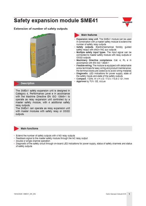
Safety expansion module SME41Extension of number of safety outputsThe SME41 safety expansion unit is designed in Category 4, Performance Level e in accordance with the Machine Directive EN ISO 13849-1 to operate as relay expansion unit controlled by a master safety module, with 4 additional safety relay outputs.The SME41 can operate as relay expansion unit with master modules with safety relay or OSSD outputs.Main features• Expansion relay unit. The SME41 module can be used in combination with a master safety module to extend the number of safety relay outputs• Safety outputs. Electromechanical forcibly guided safety relays with 4NO+1NC aux outputs• Multiple safety input types. The input signal can be connected to master safety module with relay outputs or OSSD outputs• Machinery Directive compliance. Cat. 4, PL e in accordance with EN ISO 13849-1• Flexible wiring. The module is equipped with detachable screw terminals for easy wiring and product maintenance; the terminal blocks are coded so to avoid wiring mistakes • Diagnostic. LED indications for power supply, state of the safety inputs and state of the safety outputs• Compact. 1-DIN, W x H x D: 17,5 x 110,8 x 121,1mm • Approval by TÜV. CE, cULusMain functions• Extend the number of safety outputs with 4 NO relay outputs• Feedback signal to the master safety module through the NC relay output • Double or single channel operation•Diagnostic of the safety circuit through on-board LED indications for power supply, status of safety channels and status of safety outputsReferencesType selectionFurther readingCOPYRIGHT ©2020Content subject to change. Download the PDF: StructureAAB C DAFeaturesGeneral17.5mm[0,69”]115.8mm [4,56”]121.1mm [4,77”] 17mm[4,2”]11.8mm[4,36”]Power SupplyInputsOutputsSafety parametersTo attain Cat 4, PL e according to EN ISO 13849-1, the SME41 must be used with a Cat 4, PL e master module and the NC feedback output of SME41 (contacts 51-52) must be connected in series with the start signal of the master module.Compatibility and conformityEnvironmentalConnection DiagramsDouble channel modePwr 24V (-/~)。
布士安全系统产品参考手册说明书
Intrusion DetectorReference Guide2 | Bosch Security SystemsTable of ContentsIntroduction3Blue Line Series6Commercial Series8Professional Series10Classic Line12RADION wireless18Specialty Sensors20Detector Reference Guide | 3Security you can rely onWhether you are securing a home, retail store, bank, museum, commercial business or government facility, you need dependability from your systems. With decades of experience and an unwavering dedication to high-quality and high-performing products, Bosch detectors provide best-in-class false alarm immunity and catch performance while minimizing installation time and complexity. Millions of residential and commercial users rely on Bosch for superior intrusion detection.Bosch is recognized throughout the security industry as a global leader in intrusion detection expertise. We have earned this reputation by consistently providing products that meet your needs with a focus on performance, reliability, durability, and ease of installation.Bosch detectors fulfill the requirements of standards allover the world. In the state-of-the-art Bosch laboratory, we verify that our detectors pass the most stringent requirements of each certification standard. Bosch also designs its own, even more demanding, tests to ensure the detectors are virtually immune to environmental disturbances. As a result, false alarm protection and catch performance exceed the requirements of any single country. With Bosch detectors, there is no hiding place for intruders and zero tolerance for false alarms.4| Bosch Security SystemsWall-to-Wall coverageExcellent catch performanceFirst Step Processing intelligently analyzes motionfor an almost instant response to intruders. Thedetectors automatically adjust to their environment bycompensating for temperature fluctuations, so you areguaranteed optimal performance regardless of changesin room conditions.For more challenging applications, models with SensorData Fusion technology employ a sophisticated softwarealgorithm to analyze signals from multiple sensors,including microwave, temperature, and white light levels,to make the most intelligent alarm decisions in thesecurity industry.No more false alarmsBosch detectors feature Microwave Noise AdaptiveProcessing to easily differentiate humans from falsealarm sources, such as a ceiling fan or hanging sign.For increased reliability, dual sensors process the PIR andmicrowave Doppler radar signals independently and mustagree there is an alarm before the relay activates. Thesealed optical chamber also prevents drafts and insectsfrom affecting the detector. Bosch pet and small animalimmunity provides optimal sensitivity for any application.Minimize time on the ladderBosch detectors include a number of uniquedesign features to help you get the job done fasterand more reliably.▶ A self-locking, two-piece enclosure means no more lostscrews and an easy snap-to-lock installation▶ Integrated biaxial bubble level eliminates the guessworkto ensure proper alignment, requiring one lessinstallation tool▶ The removable, gap-free, liftgate-style terminal stripr educes mounting time to mere seconds and preventsincorrect wiring to eliminate future service calls▶ Optics and electronics are assembled into the frontenclosure and sealed with a protective cover to preventdamage during installation▶ A flexible mounting height makes positioning thedetector easy, and you get no-gap coverage withoutany optical or electronic on-site adjustmentsDetector Reference Guide | 5Ideal for any applicationIntelligent intrusion detection is a delicate balance between responding to real security breaches and ignoring sources of costly false alarms. Bosch offers a choice of detector models that set the standard for reliability and rapid detection.Our intrusion detectors suit the requirements of virtually any application — from residential to large commercial to high security. They stand up to multiple challenges, including strong drafts, moving objects, and the presence of pets.Our complete line includes:▶ Passive Infrared (PIR) and TriTech®(Combination PIR and microwave Dopper radar) – Long-range – 360° ceiling mount – Pet friendly®▶ Request-to-exit PIR ▶ Glass break ▶ Seismic and shock ▶ Photoelectric beam▶ Wireless communication6| Bosch Security SystemsBlue Line Gen2 Series Detection is PowerPIRStandardPet Friendly®Quad PIR* Difficult environments include rooms with potential false alarm sources, such as: air conditioning vents, strong drafts of cold or warm air, slow moving objects such as curtains, plants, or signs hanging from the ceiling, a fan that could be running when the system is activated, under floor heating, room temperatures exceeding 86℉ (30℃), a detector that could be exposed to bright white light (car headlights, floodlights, direct sunlight, etc.)** For UL installations the operating range is 32℉ to 120℉ (0℃ to 49℃), indoor useDetector Reference Guide | 7 TriTech® (PIR + MW)Standard Pet Friendly®8| Bosch Security SystemsCommercial SeriesDetection delivered. Reliability assured.TriTech (PIR + MW)StandardAnti-maskas curtains, plants, or signs hanging from the ceiling, a fan that could be running when the system is activated, under floor heating, room temperatures exceeding 86℉ (30℃), a detector that could be exposed to bright white light (car headlights, floodlights, direct sunlight, etc.)** For UL installations the operating range is 32℉ to 120℉ (0℃ to 49℃), indoor useDetector Reference Guide | 910| Bosch Security SystemsProfessional SeriesIntelligent Motion DetectionPIRTriTech® (PIR + MW)StandardAnti-maskStandard* Difficult environments include rooms with potential false alarm sources, such as: air conditioning vents, strong drafts of cold or warm air, slow moving objects such as curtains, plants, or signs hanging from the ceiling, a fan that could be running when the system is activated, under floor heating, room temperatures exceeding 86℉ (30℃), a detector that could be exposed to bright white light (car headlights, floodlights, direct sunlight, etc.)** For UL installations the operating range is 32℉ to 120℉ (0℃ to 49℃), indoor useTriTech® (PIR + MW)Anti-mask CurtainAnti-mask CurtainClassic Line Long Range PIRLong-range* Difficult environments include rooms with potential false alarm sources, such as: air conditioning vents, strong drafts of cold or warm air, slow moving objects such as curtains, plants, or signs hanging from the ceiling, a fan that could be running when the system is activated, under floor heating, room temperatures exceeding 86℉ (30℃), a detector that could be exposed to bright white light (car headlights, floodlights, direct sunlight, etc.)** For UL installations the operating range is 32℉ to 120℉ (0℃ to 49℃), indoor useTriTech® (PIR + MW)Long-range OutdoorClassic Line Ceiling Mount PIRCurtain Wide angleLow-profile Panoramicas curtains, plants, or signs hanging from the ceiling, a fan that could be running when the system is activated, under floor heating, room temperatures exceeding 86℉ (30℃), a detector that could be exposed to bright white light (car headlights, floodlights, direct sunlight, etc.)** For UL installations the operating range is 32℉ to 120℉ (0℃ to 49℃), indoor usePIR TriTech®(PIR + MW)PIR TriTech® (PIR + MW)PanoramicHigh-Performance PanoramicPIRRecessedas curtains, plants, or signs hanging from the ceiling, a fan that could be running when the system is activated, under floor heating, room temperatures exceeding 86℉ (30℃), a detector that could be exposed to bright white light (car headlights, floodlights, direct sunlight, etc.)** For UL installations the operating range is 32℉ to 120℉ (0℃ to 49℃), indoor useRADION wireless†Superior Range and Reliability PIR TriTech® (PIR + MW) Pet Friendly® Standard Pet Friendly® Curtain Pet Friendly®Standard† Wireless peripherals require a compatible receiver. B810 RADION receiver is compatible with SDI2 bus panels (B Series and G Series); RFRC-OPT is compatible with Option bus panels; RFRC-STR is compatible with Streamline bus panels.* Difficult environments include rooms with potential false alarm sources, such as: air conditioning vents, strong drafts of cold or warm air, slow moving objects such as curtains, plants, or signs hanging from the ceiling, a fan that could be running when the system is activated, under floor heating, room temperatures exceeding 86℉ (30℃), a detector that could be exposed to bright white light (car headlights, floodlights, direct sunlight, etc.)** For UL installations the operating range is 32℉ to 120℉ (0℃ to 49℃), indoor useGlass break Door/Window Contacts OtherAcoustic Surface Mount RecessedMount Universal Transmitter SmokePortable Other Keyfob Panic Button Bill TrapPremises Wireless (ZigBee) RADION ZB PIR TriTech® (PIR+MW) StandardStandard* Difficult environments include rooms with potential false alarm sources, such as: air conditioning vents, strong drafts of cold or warm air, slow moving objects such as curtains, plants, or signs hanging from the ceiling, a fan that could be running when the system is activated, under floor heating, room temperatures exceeding 86°F (30°C), a detector that could be exposed to bright white light (car headlights, floodlights, direct sunlight, etc.)** For UL installations the operating range is 32° to 120°F (0° to 49°C), indoor use.*** Power source has capacity for an additional battery increasing the battery life from 6 to 10 years (RFPR-ZB) or from 3 to 6 years (RFDL-ZB).**** All models feature a two-piece design, self-locking enclosure, interchangeable mounting base and integrated bubble level.Specialty Request-to-exit PIRStandardHigh-performance* Difficult environments include rooms with potential false alarm sources, such as: air conditioning vents, strong drafts of cold or warm air, slow moving objects such as curtains, plants, or signs hanging from the ceiling, a fan that could be running when the system is activated, under floor heating, room temperatures exceeding 86℉ (30℃), a detector that could be exposed to bright white light (car headlights, floodlights, direct sunlight, etc.)** For UL installations the operating range is 32℉ to 120℉ (0℃ to 49℃), indoor useSpecialty Glass Break AcousticStandardComboMagneticContactSpecialty Photoelectric Beam Dual BeamShort RangeMedium Range* Difficult environments include rooms with potential false alarm sources, such as: air conditioning vents, strong drafts of cold or warm air, slow moving objects such as curtains, plants, or signs hanging from the ceiling, a fan that could be running when the system is activated, under floor heating, room temperatures exceeding 86℉ (30℃), a detector that could be exposed to bright white light (car headlights, floodlights, direct sunlight, etc.)** For UL installations the operating range is 32℉ to 120℉ (0℃ to 49℃), indoor useSpecialty Photoelectric Beam Quad BeamMedium RangeLong Range* QS — single channel QF — four channelSpecialty Seismic/ShockSeismic Shock StandardHigh-performanceStandard* Difficult environments include rooms with potential false alarm sources, such as: air conditioning vents, strong drafts of cold or warm air, slow moving objects such as curtains, plants, or signs hanging from the ceiling, a fan that could be running when the system is activated, under floor heating, room temperatures exceeding 86℉ (30℃), a detector that could be exposed to bright white light (car headlights, floodlights, direct sunlight, etc.)** For UL installations the operating range is 32℉ to 120℉ (0℃ to 49℃), indoor useN e wAccessoriesNotesDetector Reference Guide | 31 NotesA Tradition of Quality and Innovation For 125 years, the Bosch name has stood for quality and reliability. Bosch is the global supplier of choice for innovative technology backed by the highest standards for service and support. Bosch Security Systems proudlyoffers a wide range of security, safety, communications and sound solutions that are relied upon every day in applications around the world, from government facilities and public venues to businesses, schools and homes. Bosch Security Systems, Inc.130 Perinton ParkwayFairport, NY 14450 USAPhone: 800.289.0096Fax: 585.223.9180For more information please visit © Bosch Security Systems, 2016 Modifications reservedPrinted in United States | 10/16BINBR_DETECT-REF_v20161028。
《基于ISO26262的汽车电子功能安全:方法与应用》笔记

《基于ISO26262的汽车电子功能安全:方法与应用》读书札记目录一、内容描述 (2)1.1 书籍简介 (3)1.2 ISO26262标准概述 (4)二、汽车电子功能安全基础 (5)2.1 功能安全概念 (6)2.2 ISO26262标准体系 (8)2.3 功能安全等级 (9)三、ISO26262在汽车电子中的应用 (11)3.1 驱动电机控制系统 (12)3.2 电池管理系统 (14)3.3 传感器与执行器 (15)3.4 车载通信系统 (17)四、功能安全方法与技术 (18)4.1 安全需求分析 (19)4.2 安全完整性等级 (21)4.3 故障模式与影响分析 (22)4.4 控制器设计与测试 (24)4.5 人机界面设计 (26)五、案例分析 (27)5.1 案例一 (29)5.2 案例二 (29)六、实践与建议 (30)6.1 企业实施功能安全的步骤 (32)6.2 政策建议与行业标准 (33)七、总结与展望 (35)7.1 本书总结 (36)7.2 未来发展趋势 (37)一、内容描述《基于ISO2的汽车电子功能安全:方法与应用》是一本关于汽车电子系统功能安全的专业书籍,作者通过对国际标准化组织(ISO)2标准的研究和实践,详细介绍了汽车电子功能安全的基本概念、原则、方法和技术。
本书旨在帮助读者深入了解汽车电子功能安全的重要性,掌握相关的理论知识,并能够将其应用于实际的汽车电子系统中。
本书共分为五个部分:第一部分为引言,介绍了汽车电子功能安全的背景、意义和发展趋势;第二部分为ISO2标准概述,详细解读了ISO2标准的体系结构、架构和要求;第三部分为基础知识和方法,包括汽车电子系统的安全性分析、故障模式与影响分析(FMEA)、耐久性测试等方面的内容;第四部分为实际应用案例,通过分析典型的汽车电子系统实例,展示了如何将ISO2标准应用于实际项目中;第五部分为结论和展望,总结了本书的主要内容,并对未来汽车电子功能安全的发展进行了展望。
安全模块产品描述和规格说明书
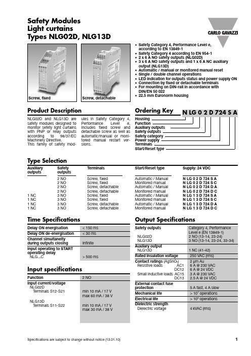
Safety Modules Product Description•Safety Category 4, Performance Level e,according to EN13849-1•Safety Category 4 according to EN954-1•2 x 6 A NO safety outputs (NLG02D)•3 x 6 A NO safety outputs and 1 x 6 A NC auxiliaryoutput (NLG13D)•Automatic / manual or monitored manual reset•Single / double channel operations•LED indication for outputs status and power supply ON•Connection by fixed or detachable terminals•For mounting on DIN-rail in accordance withDIN/EN 50 022•22.5 mm Euronorm housingType SelectionAuxiliary Safety Terminals Start/Reset type Supply: 24 VDCoutputs outputs2NO Screw,fixed Automatic / Manual N LG 0 2 D 724 S A2NO Screw, fixed Monitored manual N LG 0 2 D 724 S C2NO Screw, detachable Automatic / Manual N LG 0 2 D 724 D A2NO Screw, detachable Monitored manual N LG 0 2 D 724 D C1NC3NO Screw,fixed Automatic / Manual N LG 1 3 D 724 S A1NC3NO Screw, fixed Monitored manual N LG 1 3 D 724 S C1NC 3 NO Screw, detachable Automatic / Manual N LG 1 3 D 724 D A1NC3NO Screw, detachable Monitored manual N LG 1 3 D 724 D CLight curtainsTypes NLG02D, NLG13DOutput SpecificationsNLG02D and NLG13D aresafety modules designed tomonitor sefety light curtainswith PNP or relay outputsaccording to 98/37/ECMachinery Directive.This family of safety mod-ules in Safety Category 4,Performance Level e,includes fixed screw anddetachable screw as well asautomatic/manual or moni-tored manual restart ver-sions.Screw, fixed Screw, detachableTime SpecificationsNLG02D, NLG13DMode of OperationThe safety modules NLG02D and NLG13D monitor Elec-troSensitive Equipments (ESPE) with PNP or relay outputs according to 98/37/EC Machinery Direc-tive.If the safety system (NLG+ESPE) is correctly supplied, the input terminals of the module are activated (light beams not interrupted) and there aren’t fault condi-tions, the module is enabled to close the safety outputs and the external contactors can be energized.When the input terminals are not activated (light beams interrupted) the module is not enabled to close the safety outputs and the external contactors can not be energized.Automatic STARTProvided that the terminalsX1 and X2 (NLG02...A) orS33 and S34 (NLG13...A) areconnected, the safety out-puts close and the auxiliaryoutput opens (NLG13...A) assoon as both the moduleinputs are activated.The relevant CH1 and CH2LED turn on.Deactivating even one mod-ule input forces immediatelythe safety outputs to openand the auxiliary output(NLG13...A) to close.A new operating cycle ispossible only after deacti-vating both input contactsand then operating themagain.Manual STARTProvided that both the mod-ule inputs are activated, thesafety outputs close and theauxiliary output opens(NLG13...A) as soon as theNO STA RT pushbutton ispushed connecting X1 andX2 (NLG02...A) or S33 andS34 (NLG13...A).A new operating cycle ispossible only after deacti-vating both the moduleinputs, activating them againand pushing the START but-ton.Monitored manual STARTThe monitored manualST A RT versions (NLG...C)work as described in theprevious paragraph (ManualSTA RT) except for a mini-mum delay of 500 ms fromthe activated status of themodule inputs to the push-ing of the START button.If the inputs of the moduleare closed with the STA RTswitch already closed, thesafety outputs don’t closeand the auxiliary doesn’topen (NLG13...C): it is nec-essary to release the STARTbutton and deactivate themodule inputs before start-ing a new cycle, then oper-ate the inputs of the moduleand finally, after at least 500ms, operate the START but-ton.So if the NO STA RT buttongets welded, the outputsdon’t close anymore.General Specifications Supply SpecificationsNLG02D, NLG13DWiring DiagramsOperation Diagrams*Note:The same power supply has to be used both for the module and for the light curtain.NLG02D, NLG13DWiring Diagrams (cont.)*Note:The same power supply has to be used both for the module and for the light curtain.NLG02D, NLG13DDimensionsWiring Diagrams (cont.)。
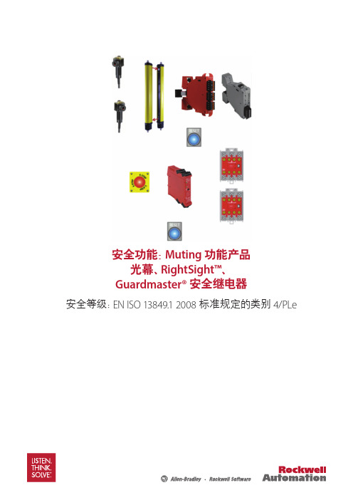
拉瑟尔自动化-安全设备系列 安全解决方案说明书
Presence sensing safety devicesSmart safety solutions that enhance productivityRockwell Automation takes safety seriouslyAllen-Bradley® GuardShield™ presence sensing safety devices from Rockwell Automation help protect personnel and equipment by detecting the presence of people and objects within a guarded area around machinery. Presence sensing safety devices are ideal for applications where personnel need frequent and easy yet safe access to hazardous areas such as near robotic welding, machining centers, stamping, hydraulic presses, filter presses or packaging equipment, etc. Our range of presence sensing safety devices cover basic on/off functionality to more advanced features including blanking and muting, all of which are available with CIP Safety over EtherNet/IP™ connectivity. Whether the need is finger, hand or whole body detection, our knowledgeable team of experts understand how to apply a comprehensive safety solution for your manufacturing facility.Built to global standards for high reliability, stability and quality, Rockwell Automation solutions are ideally suited for applications where personnel safety is a priority. Our innovative products and services help protect your people,machinery, and environment while maximizing uptime.G u a r d S h i e l d 450L -BG u a r d S h i e l d 450L -EG u a r d S h i e l d 440L T y p e 4 P O CS C 300 H a n d D e t e c t i o n S a f e t y S e n s o rM i c r o 400 w i t h M S R 41 C o n t r o l l e rM i c r o 400 w i t h M S R 42 C o n t r o l l e rG u a r d S h i e l d 440L -T y p e 4 P A C445L S a f e 4 P A CA r e a A c c e s s C o n t r o l (A A C ) S i n g l eB e a mS a f e Z o n e S a f e t y L a s e r S c a n n e r sM a t G u a r d S a f e t y M a t sS a f e d g e S a f e t y E d g e sPRESENCE SENSING SAFETY DEVICESVariable speed and servo drives Safety contactors GuardLogix® and Compact GuardLogixSafety relaysPRESENCE SENSINGMatGuard™ pressure sensitive safety mats around the entryarea of a machine process help to detect the presence ofTongue and hingeswitchesCable pull switches Enabling switches Safety light curtainsand scannersPressure sensitivedevices76451328POINT OF OPERATION CONTROL (POC)POC safety light curtains are typically designed to detect the presence of a finger or hand. These devices are usually positioned in front of the point of operation hazard, close to the machine opening. However, they may also be used forperimeter guarding applications. They can be mounted vertically or horizontally.PERIMETER ACCESS CONTROL (PAC)PAC safety light curtains are used as whole body detection devices for detection of personnel or large objects when they pass through the sensing field. They are typically positioned around an area or in front of a process entry or exit area. Typically they do not require frequent interaction between personnel and the hazard during regularoperation. Multi-sided access control is attained through the use of corner mirrors.Non- contact switchesE-stops Power isolators Trapped key switchesFIXED AND FLOATING BLANKINGThe blanking function is a means of disabling one or more sections of a POC light curtain’s sensing field. There are two blanking modes: fixed for static and floating for moving disabled sections.Functionality and advanced featuresAllen-Bradley Guardmaster safety productsGuardShield 440L Type4 PAC445L Safe4 PACSafedge™ Safety EdgesSafeZone™ Safety Laser ScannersSC300 Hand Detection Safety SensorPresence sensing safety devicesGuardShield 450L-B and GuardShield 450L-E Safety Light CurtainsPOINT OF OPERATION CONTROL (POC) FOR FINGER OR HAND PROTECTIONAllen-Bradley® GuardShield POC safety light curtains are unlike traditional safety light curtains, which are based on separate transmitter and receiver units. Patented technology allows each transceiver to be used as a transmitter or receiver via an innovative plug-in module. These light curtains are available with CIP Safety over EtherNet/IP connectivity and TÜV certified PLe, Type 4 IEC 61496-1/-2, SIL CL3per EN ISO 13849-1 and IEC 62061.• Simple on/off functionality• Innovative plug-in modules (available separately) for application flexibility, advanced functionality and reduced inventory costs• Protection heights up to 1950 mm (76.7 in.) with active sensing field along the entire length• Compact design 30 mm x 30 mm (1.18 in. x 1.18 in.)• Integrated laser alignment system helps provide quick and more reliable installation (450L-E only)Product spotlightRockwell Automation smart safety products enhance safety while providing connectivity through The Connected Enterprise. Allen-Bradley Guardmaster smart safety devices featuring EtherNet/IP connectivity or GuardLinkenabling technology deliver information, diagnostics, advanced functionality and flexibility, while enhancing safety Universal plug-in forG u a r d S h i e l d 450L -BG u a r d S h i e l d 450L -EG u a r d S h i e l d 440L T y p e 4M i c r o 400 w i t h M S R 41 C o n t r o l l e rM i c r o 400 w i t h M S R 42 C o n t r o l l e rG u a r d S h i e l d 440L T y p e 4 P A CG u a r d S h i e l d 445L S a f e 4 P A CA r e a A c c e s s C o n t r o l (A A C ) S i n g l eB e a mPublication GLSAFE-BR001C-EN-P – January 2021 | Supersedes Publication GLSAFE-BR001B-EN-P – September 2018Copyright © 2021 Rockwell Automation, Inc. All Rights Reserved. Printed in USA.Allen-Bradley, Compact GuardLogix, expanding human possibility, GuardLink, GuardLogix, Guardmaster, GuardShield, MatGuard, Rockwell Software,Safedge and SafeZone are trademarks of Rockwell Automation, Inc.All other trademarks and registered trademarks are property of their respective companies.Presence sensing safety accessoriesConnect with us.。
克朗斯吹瓶机报警故障处理
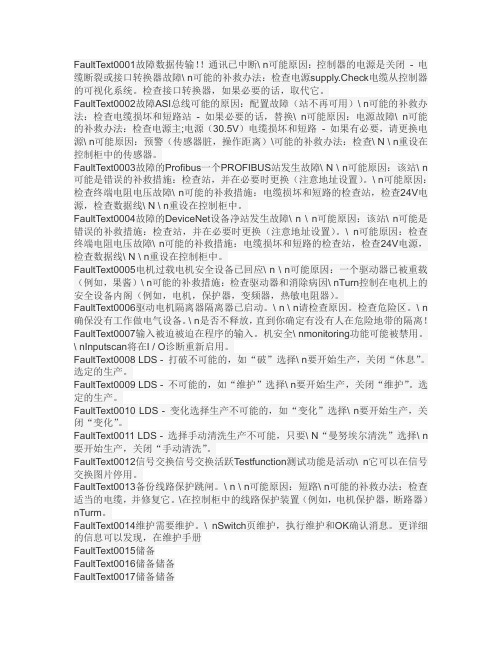
FaultText0001故障数据传输!!通讯已中断\ n可能原因:控制器的电源是关闭- 电缆断裂或接口转换器故障\ n可能的补救办法:检查电源supply.Check电缆从控制器的可视化系统。
检查接口转换器,如果必要的话,取代它。
FaultText0002故障ASI总线可能的原因:配置故障(站不再可用)\ n可能的补救办法:检查电缆损坏和短路站- 如果必要的话,替换\ n可能原因:电源故障\ n可能的补救办法:检查电源主;电源(30.5V)电缆损坏和短路- 如果有必要,请更换电源\ n可能原因:预警(传感器脏,操作距离)\可能的补救办法:检查\ N \ n重设在控制柜中的传感器。
FaultText0003故障的Profibus一个PROFIBUS站发生故障\ N \ n可能原因:该站\ n 可能是错误的补救措施:检查站,并在必要时更换(注意地址设置)。
\ n可能原因:检查终端电阻电压故障\ n可能的补救措施:电缆损坏和短路的检查站,检查24V电源,检查数据线\ N \ n重设在控制柜中。
FaultText0004故障的DeviceNet设备净站发生故障\ n \ n可能原因:该站\ n可能是错误的补救措施:检查站,并在必要时更换(注意地址设置)。
\ n可能原因:检查终端电阻电压故障\ n可能的补救措施:电缆损坏和短路的检查站,检查24V电源,检查数据线\ N \ n重设在控制柜中。
FaultText0005电机过载电机安全设备已回应\ n \ n可能原因:一个驱动器已被重载(例如,果酱)\ n可能的补救措施:检查驱动器和消除病因\ nTurn控制在电机上的安全设备内阁(例如,电机,保护器,变频器,热敏电阻器)。
FaultText0006驱动电机隔离器隔离器已启动。
\ n \ n请检查原因。
检查危险区。
\ n 确保没有工作做电气设备。
\ n是否不释放,直到你确定有没有人在危险地带的隔离!FaultText0007输入被迫被迫在程序的输入。
安装说明-Compact 5000 I O 数字量 8 点安全拉出型输入模块说明书

安装说明Compact 5000 I/O 数字量 8 点安全拉出型输入模块目录号 5069-OBV8S 、5069-OBV8SKThe 5069-OBV8S 和 5069-OBV8SK 模块是 8 点安全拉出型输入模块。
这些模块在安全控制网络上提供满足以下要求的安全 I/O ,该等要求包括 SIL CL3 和 PLe, Cat. 4,如 IEC 61508、IEC 61511、IEC 62061 和 ISO 13849-1 中所规定。
该模块提供拉出型输出和双极性类型输出。
您可将 Compact 5000™ I/O 安全模块用作带 CompactGuardLogix®5380 控制器的本地和远程 I/O 模块,以及带 Compact GuardLogix 5380 和 GuardLogix 5580 控制器的远程 I/O 模块。
5069-IB8SK 模块提供与 5069-IB8S 模块相同的功能,但具有保形涂层,有助于在恶劣环境中提供保护。
使用 Studio 5000 Logix Designer® 软件配置模块。
Compact GuardLogix 5380 和 GuardLogix 5580 控制器必须使用 32.011 或更高的固件版本,才可使用 Compact 5000 I/O 安全模块。
Compact 5000 I/O 安全模块采用生产者/消费者通信模式。
生产者/消费者通信模式是模块与其他系统设备之间的一种智能数据交换,在通信过程中,每个模块都会生成数据,而不是先被轮询。
有关如何使用 Compact 5000 I/O 模块的更多信息,请参见第12页的其他资源中列出的出版物。
变更摘要主题页码关于模块5安装系统5安装可拆卸端子块7安装模块8安装终端盖9对可拆卸端子块进行接线9断开电线与可拆卸端子块之间的连接9使用束线带10为系统供电10拆卸模块10技术参数11其他资源12主题页码删除接线图有关如何连接模块的信息,请参阅中第12页的其他资源列出的出版物不适用Compact 5000 I/O 数字量 8 点安全拉出型输入模块ATTENTION:Read this document and the documents listed in the Additional Resources section about installation, configuration and operation of this equipment before you install, configure, operate ormaintain this product. Users are required to familiarize themselves with installation and wiring instructions in addition to requirements of all applicable codes, laws, and standards.Activities including installation, adjustments, putting into service, use, assembly, disassembly, and maintenance are required to be carried out by suitably trained personnel in accordance with applicable code of practice.If this equipment is used in a manner not specified by the manufacturer, the protection provided by the equipment may be impaired.注意:在安装、配置、操作和维护本产品前,请阅读本文档以及“其他资源”部分列出的有关设备安装、配置和操作的相应文档。
罗克韦尔自动化 MSR42 安全继电器和 MSR45E 扩展模块安全功能应用说明书
3
简介
本安全功能应用说明阐述了如何对 MSR42 安全继电器以及带 GSR SI 安全继电器的 MSR45E 扩展模块进行接线、配置和集成,以监控 440L GuardShield™ 光幕,从而创建 一个具有附加急停功能的双传感器 L 型屏蔽 (单向屏蔽) 系统。如果有物体中断光幕 视野 (光幕未被屏蔽的情况下),或在监控电路中检测到故障,则 MSR42/MSR45E 将使 一对 100S 冗余接触器断电,以停止运动。每当按下急停按钮时,GSR SI 使接触器断电, 以停止运动。 当指定尺寸的物体按正确顺序通过屏蔽传感器时,光幕将被屏蔽。此时允许物体继续 通过光幕,而不会停止运动。一旦物体离开光幕视野,将立即终止屏蔽。 提供了屏蔽超控功能,以清除滞留在受监视区域的物体。 如果物体从“非屏蔽”方向中断光幕视野,或没有在配置的时间间隔内按正确顺序通 过屏蔽传感器,则 MSR42/MSR45E 将使接触器断电。
ਸ๔ǖޅ၃ೠࠚ (ISO 12100)
1
Ҿඇࠀీ๎՚
2
߳Ҿඇࠀీڦ༬Ⴀࡀ߭
3
ඓۨ߳ҾඇࠀీႴ ڦPL (PLr)
ຐǖํ၄ࢅ PL ೠࠚ
光幕屏蔽安全功能
本应用项目包括三个安全功能:
1. 由光幕启动的危险运动急停。 2. 光幕屏蔽。 3. 由急停按钮启动的危险运动急停。 该系统执行停止类别 0 停止。允许运动滑行停止。
只要进行正确屏蔽,即可中断光幕视野,而无需释放安全接触器。每当光幕被屏蔽时,屏蔽灯通电。
物料清单
目录号 440L-P4KL1280YD
889D-F8AB-2
440G-A27011
889D-F4AC-2 60-2649 92-89 440R-P226AGS-NNR 800FM-G611MX10
克朗斯直线验瓶机EBI培训教程bd
krones Technology
机器结构-1
1.高矮瓶\倒瓶检测及剔除1装置 2.侧壁1/划痕检测
6.夹瓶皮带 7.总电源开关
3.入口剔除1装置气源及入口喷水装 8.清洗气枪及设备总气源调节阀 置控制气 9.设备总气源入口 4.机器工作状态指示灯 10.侧壁2检测 5.触摸屏显示及操作面板 11.剔除器2/3 12.剔除器2/3气源
krones Technology
常见故障-1 1. 阻塞出口 [39]: 在侧壁2出 口有一个检 测是否堵瓶 的检测开关 ,发生此故 障时必须把 挡住堵瓶开 关的瓶子移 走,方可复 位
krones Technology
常见故障-2
2. 出瓶1出 瓶带卡住 [41]: 排除链道上, 有一个检测排 除链道堵瓶的 检测开关,发 生此故障时, 检查排除链道 是否堵瓶,把 挡住此光电开 关的瓶子移开 ,方可复位
故障图像显示画面,机器 发生故障将在此画面上显 示相对应的故障出错位置 ,便于查找故障及分析
故障信息显示画面, 显示故障名称及故障 代码
krones Technology
1. 总计进口:进入机器的瓶子 总数 总计排除:被机器剔除出去 的瓶子总数 2. 各个检测单元剔除出去的瓶 子数量 3. 容器进口:剔除器1剔除出 去的瓶子数量 容器出口:剔除器2剔除出 去的瓶子数量 污染输送带:剔除器3剔除 出去的瓶子数量 生产输送带:通过机器进入 酒机正式灌装的瓶子数量 4. 各数据统计曲线报表 5. 选择I,激活相对应的 检测单元
krones Technology
触摸屏操作-1
1. 用户名输入 2. 进入代码(密 码),不同的用 户名对应不同的 进入代码,同时 也具有相对应的 权限 3. 小键盘用来输 入进入代码的, 当进入代码输入 完成后,请点击 行(相当于确认 键) 4. 机器启动后要 求15分钟之内进 行登陆
卡特C15 ACERT 块处理引擎操作规范说明书

Power Train
Move material more efficiently with improved power and control.
Transmission Neutralizer Pedal
• Extends service brake life by neutralizing transmission as service brakes are applied.
allows the operator to pre set linkage positions and achieve faster cycle times.
3rd Valve Hydraulic Control
• Provides versatility through the ability to control a specialized attachment.
986H
Block Handler
Engine Engine Model Gross Power – SAE J1995 Net Power – ISO 9249
Cat® C15 ACERT™
335 kW
449 hp
305 kW
409 hp
Operating Specifications Operating Weight
controls injection pressure over the entire engine operating range. This gives the C15 complete control over injection timing, duration and pressure. • Extended engine life through Cat components with proven reliability. • The Advanced Diesel Engine Management (ADEM™) A4 electronic control module manages fuel delivery to optimize performance and provide quick engine response.
克朗斯电气知识

克朗斯电气知识XXXXXX。
XXX.XXX of the Diagram:1.Basic knowledge of XXX diagrams2.Krones Circuit DiagramPart 1: Diagram n Column - includes the drafting time。
XXX。
and XXX.Part 2: Diagram Lookup Column - provides n on the n ofXXX corresponding to the diagram.Part 3: Circuit n Diagram - XXX with the diagram using n from Part 2.Part 2 Enlarged View:Meanings of each part:A: Equipment - machine number KB: Project number - machine project number。
001 represents the first bookC: Mounting n - n of electrical components in the control。
XXXSKFKAKKKPVKRKSVPVRKASSSUSVTBBUVVSDXXXMain Control XXXFiller CarouselXXXTerminal Box Grouped Valves Terminal Box Ring Bowl Terminal Box Roll-On Sealer Grouped ValvesRinser CarouselControlGuardsRoll-On XXXXXXTransfer Grouped Valves XXXMachine TableXXX主控制柜Filler转台操作台阀站控制柜转塔旋盖机顶部电柜阀站电器部件Rinser转台机器旁边控制柜安全门旋盖机产品输送带中间转换阀组瓶盖浸泡杀菌机台底下的编码器,电机上图中,XXX代表主控制柜,1表示第一个D: Process-Unit。
SINUMERIK MC Safety Integrated 开机调试手册说明书
前言
1
基本安全说明
2
基本原理
3
F-PLC 的安全程序
4
驱动集成的安全功能
5
6 驱动集成的安全功能的控制方
式
调试和配置
7
验收测试
8
诊断
9
更换软/硬件
10
数据描述
11
系统特性
12
附录
A
法律资讯 警告提示系统
为了您的人身安全以及避免财产损失,必须注意本手册中的提示。人身安全的提示用一个警告三角表示,仅与财产损 失有关的提示不带警告三角。警告提示根据危险等级由高到低如下表示。
3 基本原理 ........................................................................................................................................ 35
3.1
F-PLC 的安全功能......................................................................................................... 35
1.6
SINUMERIK 操作软件 ................................................................................................... 21
1.7
按照 SINUMERIK 来配置报文 ........................................................................................ 22
克朗斯吹瓶机电路图注解

Legend Line / Anlage
Legend
-BM1 -HM -ET1 -FU1 = Blowing modul = Heating modul = Labeller = Filler -BM1 -HM1 -ET1 -FU1
Legende
= Blasmaschine1 = Heizmodul = Ekettiermaschine1 = Füller1
2 numbers identify the page number in between the group/ Die 2 ersten Ziffern zeigen die Seitenzahl innerhalb der Gruppe
11
Page 11
25.07.2013
krones Contiform
K012-E69.0 Central lubrication/ Zentralschmierung
Page 16
25.07.2013
krones Contiform
Example 2 group 2801, page 01 / Gruppe 2801, seite 01
A012
01
Page 17
25.07.2013
Legende
= Personenschutz = Grundausstattung = Ablaufsteuerung
-5501
= Valve control
-3501 = Kühlung Heizmodul -5501 = Ventilsteuerung
Page 7
25.07.2013
krones Contiform
B124
A012
12
布莱尚安全产品参考指南说明书

Quick Guide B Seriesand G Series Control PanelsSecurity you can trustIP Video, BIS, BVMS IP Video, Access Control, BIS, BVMS IP Video, Access Control, BIS, BVMS IP Video, Access Control, BIS, BVMSIntrusion Applications Fire ApplicationsType Text Text w/ function keys Touch screen Touch screen CombinationIntrusion + Fire Fire Commercial type number (CTN)B915 / B915i B920B942B B942W B925FB926F KeypadsMaterial description PTSN (Single phone line)Two-way cellular*Two-way cellular*Remote cellular interface Ethernet (Two-way IP) Commercial type number (CTN)B430B442 G Series B443B450B426Communication modulesB308Octo-OutputModuleB920Text w/functionkeysB520AUXPowersupplyB6512/B5512B915/B915iTextDE-45-18TransformerEU plugD135ALow-BatteryDisconnectModuleB942TouchscreenD125BDual Class BInitiatingModuleB2012–wirepoweredloopF220/F220–B6RSmoke Detectorplus BaseB443Cellular(HSPA+ SIMRequired)B442CellularGPRSD1267Ah BatteryB942WTouchscreenB208Octo-inputModuleD8108AAttackResistanceEnclosureB8103LargeenclosureD137MountingbracketICP–EZTSUniversalTamperB10MediumenclosureB12Mountingplate forD8103 &D8108AD5500CURPSInstallerServicesPortal(availablein alllanguages)D5500CU–LITERPS LiteB99USBCableB450RemoteCellularInterfaceB430Telephone(PSTN)B426EthernetSDI orSDI2D122/D122LBatteryharnessD1640TransformerD138Mounting bracketB9512G/B8512GB & G Series Control Panels _ Intrusion ApplicationB6512/B5512/B4512/B3512EnclosuresPower*KeypadsI/O ExpansionResidential FireAccessoriesCommunicatorsProgramming*Country specific variants may applyRFBTBilltrapRFSMSmokeDetectorD8223D8224D8225HID ProxARD–AYK12EM MiniMullion RFIDARD–AYQ12EM, vandal-resistant RFIDARD–AYH12EM Mount RFIDARD–AYJ12EM MullionRFIDARD-FPBEPPR-OCARD-FPBEPHP-OCBiometricB901AccessModuleD8229keypadRemote SecurityControlMobile AppPIR, Pet Friendly12 x 12 m.ISC–BPR2–W12PIR12 x 12 m.DS936Low-profilePIR360º x 7 m.ISC–BPQ2–W12Quad PIR12 x 12 m.ISC–PPR1–W16PIR16 x 21 m.DS160DS161DS150iDS151iRFDW–RMRecessedContactRFDW–SMSurfaceContactRFGBGlassBreakDetectorRFUNUniversalTransmitterB810WirelessReceiverRFRPWirelessRepeaterRFPR–C12Curtain PIR,Pet Immune40 x 5 ft.RFPR–12Standard PIR,Pet Immune40 x 40 ft.RFPB–SBRFPB–TBPanicButtonsRFKF–TBSRFKF–FBSArm/DisarmKeyfobsSee for a complete product list.Any BoschIP cameraD6100IPv6CommunicationsReceiver/Gateway,CPU v.61.10.00D6600CommunicationsReceiver/Gateway,CPU v.01.10.00DS1101iDS1103iDS1102iDS1108iWired SensorsIntegrationAccessoriesMobile AppsKeypadsWireless Access Control (B6512, B8512G and B9512G) Professional Series Ceiling Mount Blue Line Gen2RADION ModuleRequest-to-exit Glass BreakIP VideoConettix ReceiversReadersARD–SER40–WIARD–SER10–WIARD-SERK40-WIARD-SER90-WILectussecureiCLASS,Wiegand DS939High-performancePIR360º x 21 m.ARD-AYCF64EM keypadARD-AYCE65BEM keypad,vandal-resistantARD-AYZ12EM long rangereaderISC–BPR2–WP12NotesA tradition of quality and innovationFor over 125 years, the Bosch name has stood for quality and reliability. Bosch is the global supplier of choice for innovative technology, backed by the highest standards for service and support. Bosch Security Systems proudly offers a wide range of security, safety, communications and sound solutions that are relied upon every day in applications around the world, from government facilities and public venues to businesses, schools and homes.Bosch Security Systems B.V.Torenallee 495617 BA EindhovenPhone: +31-40-2577200For more information please visit© Bosch Security Systems2018 Modifications reserved。
OXYMAT 6 气体分析仪安全手册说明书

Trademarks
All names identified by ® are registered trademarks of the Siemens AG. The remaining trademarks in this publication may be trademarks whose use by third parties for their own purposes could violate the rights of the owner.
Danger
indicates that death or severe personal injury will result if proper precautions are not taken.
Warning indicates that death or severe personal injury may result if proper precautions are not taken.
- 1、下载文档前请自行甄别文档内容的完整性,平台不提供额外的编辑、内容补充、找答案等附加服务。
- 2、"仅部分预览"的文档,不可在线预览部分如存在完整性等问题,可反馈申请退款(可完整预览的文档不适用该条件!)。
- 3、如文档侵犯您的权益,请联系客服反馈,我们会尽快为您处理(人工客服工作时间:9:00-18:30)。
Transmission of safe data to monitor 模块安全数据传送
If safe data from old chip card is not atuo copied to the master, then the release code needs to be entered again. 在新的ASI安全主控制器上 电后,系统如不是自动拷 贝安全数据到主控制器上 ,则需进行安全代码的手 动输入。
If the old card with a released configuration is detected during start up with the new master, the safe data will be copied into the new master. 在新的ASI安全主控制器上电后,系统会自动 检测老卡中的安全数据,然后自动拷贝安全 数据到新的主控制器上。
krones Beispieltext
ASI safety master chipcard replacement ASI 安全主控制器模块数据卡更换
After machine power off, then can do chip card replacement. Insert the old card to the new master. 机器的主控制柜需断电后才可进行安全数据 卡的 更换, 在新的ASI安全主控制器上插入原 来的老卡。
The PIN is 9401 or 0000 PIN 代码是9401 或是 0000
krones Beispieltext
Transmission of safe data to monitor 模块安全数据传送
Using the arrow keys on the monitor to scroll, you can reach the image with release code, then input this release code, confirm with OK button. 在ASI安全主控制器 上用下箭头翻页可找 到安全代码, 然后手 动输入该安全代码, 用OK按钮确认。