PROFIBUS-DP协议简介(和利时)
Profibus-DP在ABB传动控制系统中的应用
Profibus-DP在ABB传动控制系统中的应用什么是Profibus-DP?Profibus(Process Field Bus)是一种用于自动化领域的数字通信协议,由多家德国公司联合开发,其数据传输速度可达12Mbps,常用于工业现场作为工业网络的一种。
Profibus可分为Profibus-PA和Profibus-DP两种,前者用于过程自动化,如化工、石化等领域,后者用于工厂自动化,如机床、自动化装备等领域。
Profibus-DP(Decentralised Periphery)是基于Profibus技术的工厂自动化通信协议,它可以将PLC(可编程逻辑控制器)与I/O(输入/输出)设备相连接,用于通过总线传输不同类型的信号和数据,实现工业现场设备的实时控制和监控。
ABB传动控制系统介绍ABB(ASEA Brown Boveri)是世界领先的电气设备制造商,创建于1883年,总部位于瑞士苏黎世市。
ABB提供了全面的电气解决方案,涵盖了从传输到转换再到优化各个层面的应用。
ABB传动控制系统是ABB集团旗下的一种智能化的工业自动化系统,其主要功能是负责电机的控制和驱动,实现物料输送、工件加工、机器人等设备的运行与协调。
它能够通过各种方式控制工程的开关和过程控制的变量,并可以处理过程中的各种异常情况。
Profibus-DP在ABB传动控制系统中的应用由于其高速度和实时性,Profibus-DP十分适合应用于ABB传动控制系统中,能够帮助工业现场控制和监控各种设备并提高生产效率。
下面是Profibus-DP在ABB传动控制系统中的具体应用:1. 与AC500 PLC相连接AC500是ABB公司的一种PLC,具有高速计算能力和易于安装配置的特点。
与Profibus-DP总线结合所构成的工业控制系统可用于数据采集、监控、控制和诊断。
AC500可以将得到的信号通过Profibus-DP传输到其他设备,达到对现场工艺的控制和监控。
Profibus_DP概述

应用层(第七层)及PROFIBUS行规
ISO/OSI参考模型的应用层提供用户需要的各种通信服务。 FMS使用LLI(Lower Layer Interface)实现连接的建立及监控。 S7是一种优化的协议,可以通过PROFIBUS实现编程监控等功能。 DP行规规定了相关应用的参数和行规的使用,使不同生产商的DP设 备使用相同的标准。 1: NC/RC行规 2: 编码器行规 3:传动行规 4:操作员控制和过程监控行规
11 0 1 0
通过示波器可以监控信号传输的状态
第四页,共47页。
PROFIBUS
数据传输时的信号形状 •如果电缆过长,则信号开始变圆滑
第五页,共47页。
PROFIBUS
PROFIBUS 电器接口需要注意的问题
1:PROFIBUS接头问题
大于1.5M时,避免连接站的电容性负载引起的导线反射,需要使用附加轴 向电感的总线接头。
PROFIBUS物理层支持光纤通信
第二页,共47页。
PROFIBUS总线段
5V
390Ohm
220Oh m
390Oh m
0V
……
5V
总线终端 电阻开关
390Oh m
220Oh m
390Oh m
连PROFIBUS电缆
0V
第三页,共47页。
PROFIBUS
数据传输时的信号形状
B导线
二进制信号
A导线
10
PROFIBUS(RS485)使用的是屏蔽双绞电缆,PROFIBUS的 第一层实现对称的数据传输,一个总线段的导线是屏蔽双 绞电缆,段的两端各有一个终端电阻。
传输速率: 9.6Kbit/sec~12Mbit/sec
和利时系统简介
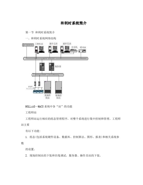
和利时系统简介第一节和利时系统简介一、和利时系统网络结构HOLLiAS—MACS系统中各“站”的功能工程师站工程师站运行相应的组态管理程序,对整个系统进行集中控制和管理。
工程师站主要有以下功能:1. 组态(包括系统硬件设备、数据库、控制算法、图形、报表)和相关系统参数的设置。
2. 现场控制站的下装和在线调试,服务器、操作员站的下装。
3. 在工程师站上运行操作员站实时监控程序后,可以把工程师站作为操作员站使用。
操作员站操作员站运行相应的实时监控程序,对整个系统进行监视和控制。
操作员站主要完成以下功能:1. 各种监视信息的显示、查询和打印,主要有工艺流程图显示、趋势显示、参数列表显示、报警监视、日志查询、系统设备监视等。
2. 通过键盘、鼠标或触摸屏等人机设备,通过命令和参数的修改,实现对系统的人工干预,如在线参数修改、控制调节等通讯站和其它设备通讯服务器服务器运行相应的管理程序,对整个系统的实时数据和历史数据进行管理。
现场控制站现场控制站运行相应的实时控制程序,对现场进行控制和管理。
现场控制站主要运行工程师站所下装的控制程序,进行工程单位变换、数据采集和控制输出、控制运算等。
HOLLiAS—MACS系统中的“网络”包括1. 监控网络MNET特点:1 冗余高速以太网链路2. 使用五类屏蔽双绞线或光纤将各个通讯节点连接到中心交换机上3. 节点有工程师站、操作员站、服务站4. 采用TCP/IP通讯协议5. 监控网络上各个节点用固定分配的IP地址进行标识。
为实现监控网络的冗余,网中每个节点的主机都配有两块以太网卡,一般在工程上将两块以太网卡分别连接到130网段和131网段的交换机上。
监控网络的前两位IP地址分别为130.0和131.0,后两位则可以自行定义。
对于工程师站和操作员站的计算机,我们把它看作同一类计算机,进行统一编号。
工程上编号的惯例为:2.系统网络SNET1. 冗余高速工业以太网2. 采用HSIE 通讯协议3. 使用五类屏蔽双绞线或光纤将各个通讯节点连接到中心交换机上4. 节点有服务站、现场控制站3.控制网络CNET1. 位于现场控制站内部2. Profibus-DP现场总线3. 采用带屏蔽的双绞铜线连接4. 节点主要有DP主站(主控单元)和DP从站(智能I/O单元)5. 完成实时输入/输出数据和从站设备诊断信息的传送6. 站地址为0-1251. Profibus-DP现场总线:Profibus是作为德国国家标准DIN 19245和欧洲标准prEN 50170的现场总线。
PROFIBUS-DP

发送数据无需应答SDN
FDL-DATA.request(DSAP, SSAP, Rem-add, Lsdu, Serv-class) FDL-DATA.indication(DSAP, SSAP, Loc-add, Rem-add, L-sdu, Serv-class) FDL-DATA.confirm(DSAP, SSAP, Rem-add, Serv-class, L-status)
FDL-DATA-ACK.request(DSAP, SSAP, Rem-add, Lsdu, Serv-class) FDL-DATA-ACK.indication(DSAP, SSAP, Loc-add, Rem-add, L-sdu, Serv-class) FDL-DATA-ACK.confirm(DSAP, SSAP, Rem-add, Serv-class, L-status)
从站
1.
2.
Profibus-DP系统通信中的响应方,不能主 动发送数据请求 有紧凑型从站和模块型从站
Profibus-DP的总线访问控制
1.
总线访问控制要求
总线主站节点必须在确定的时间范围内获 得足够的机会来处理其通信任务
2.
主站与从站的数据交换必须快速且有很少 的协议开销
混合总线访问控制机制:主站之间采用令 牌控制,主站与从站采用主从控制方式。
SDN
SDN允许本地用户同时向多个甚至所有远 程用户发送数据。所用接收到数据的远程 站不作应答。本地用户在申请SDN服务后 立即传送原语FDL-DATA.confirm给本地用 户,原语中的参数L-status仅可表示发送成 功或本地FDL错误,不能显示远程站是否正 确接收。
PROFIBUS-DP介绍ppt课件

有的S7-300/400 CPU配备有集成的DP接口,S7-200/300/400 也可以通过通信处理器(CP)连接到PROFIBUS-DP
3
二、PROFIBUS的物理层
ISO/OSI参考模型的物理层是第1层,PROFIBUS可以使用多种 通信媒体,例如带屏蔽的双绞线、光纤、红外线、导轨以及混 合方式。传愉速率为9.6kbit/s一12Mbit/s,每个DP从站的输入数 据和输出数据最大为244B。使用屏蔽双绞线电缆时最长通信距
PROFIBUS-DP符合EIARS-485标准(也称为H2),采用价格便 宜的屏蔽双绞线电缆,电班兼容性(EMC)条件较好时也可以 使用不带屏蔽的双绞线电缆。一个总线段的两端各有一套有源 的总线终端电限。
PROFIBUS的站地址空间为0~127,其中的127为广播用的地
址,所以最多能连接127个站点。一个总线段最多32个站,超过 了必须分段,段与段之间用中继器连接。中继器没有站地址,
①以PC为硬件平台的2类主站 PC加PROFIBUS网卡可以做2类主站。程软件来做编程设备, 用PC和WinCC等组态软件做监控操作站。
②操作员面板/触摸屏(OP/TP) 操作员面板(OP)和触摸屏(TP)用于操作人员对系统的控制和
⑥使用PROFIBUS网卡的PC
10
3.2、2类DP主站
2类DP主站是DP网络中的编程、诊断和管
理设备。2类DP主站除了具有1类主站的功
能外,在于1类DP主站进行数据通信的同
时,可以读取DP从站的输入/输出书和当
前的组态数据,可以给DP从站分配新的总
线地址。
11
3.2、2类DP主站
下列设备可以作为2类DP主站:
profibus协议
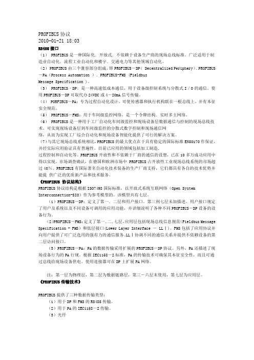
PROFIBUS协议2010-01-21 18:03RS485接口(1) PROFIBUS是一种国际化.开放式.不依赖于设备生产商的现场总线标准。
广泛适用于制造业自动化.流程工业自动化和楼宇.交通电力等其他领域自动化。
(2) PROFIBUS由三个兼容部分组成,即PROFIBUS-DP( Decentralized Periphery).PROFIBUS -PA(Process Automation ).PROFIBUS-FMS (FieldbusMessage Specification )。
(3) PROFIBUS–DP: 是一种高速低成本通信,用于设备级控制系统与分散式I/O的通信。
使用PROFIBUS-DP可取代办24VDC或4-20mA信号传输。
(4) PORFIBUS-PA:专为过程自动化设计,可使传感器和执行机构联在一根总线上,并有本征安全规范。
(5) PROFIBUS-FMS:用于车间级监控网络,是一个令牌结构.实时多主网络。
(6) PROFIBUS是一种用于工厂自动化车间级监控和现场设备层数据通信与控制的现场总线技术。
可实现现场设备层到车间级监控的分散式数字控制和现场通信网络,从而为实现工厂综合自动化和现场设备智能化提供了可行的解决方案。
(7)与其它现场总线系统相比,PROFIBUS的最大优点在于具有稳定的国际标准EN50170作保证,并经实际应用验证具有普遍性。
目前已应用的领域包括加工制造.过程控制和自动化等。
PROFIBUS开放性和不依赖于厂商的通信的设想,已在10多万成功应用中得以实现。
市场调查确认,在德国和欧洲市场中 PROFIBUS占开放性工业现场总线系统的市场超过40%。
PROFIBUS有国际著名自动化技术装备的生产厂商支持,它们都具有各自的技术优势并能提供广泛的优质新产品和技术服务。
《PROFIBUS 协议结构》PROFIBUS协议结构是根据ISO7498国际标准,以开放式系统互联网络(Open System Interconnection-SIO)作为参考模型的。
第5章PROFIBUS-DP

传输距离和使用的传输介质及波特率有关。 PROFIBUS的特征码(Character)由11位(bits)组成,即1个 起始位(起始位总为0),8个数据位,一个校验位和一个停止位 (停止位总为1)
2
2007.2 V2.0
现场总线技术及应用教程 Copyright by Wang Yonghua
5
5.1 PROFIBUS-DP的基本概念
● PROFIBUS-DP 及DP-V0
4. 总线存取过程
PROFIBUS-DP的总线存取过程遵循以下原则:
各主站之间采用令牌(Token)交换的规则,按序交换令牌。令 牌相当于一种权力,谁握有令牌,谁就有对总线的使用权力,没 有令牌的一方只有等待。令牌只有一个,所以同一时间内只能有 一个主站拥有令牌,这就避免了多人发布命令而造成的混乱。在 拥有令牌的时间内,该主站必须完成它应该完成的任务。 从站只能接受主站的请求而产生响应,它不能向主站提出请求。 每个主站都有它自己所控制的从站,它不能控制其他主站的从站, 但它可以读取其他从站的数据。 第二类主站可以对任何从站进行读取操作,但这种操作是非循环 的。
2007.2 V2.0
现场总线技术及应用教程 Copyright by Wang Yonghua
10
5.2 DP各站的功能及通信
● PROFIBUS-DP 及DP-V0
1. 功能
主站(主要指1类主站) 把输出数据送往从站,如果需要 的话也可以得到从站的输入数据。它的主要功能有:
控制托肯的传递; 负责把新的站点放入总线中; 和组态好的从站进行数据交换; 检测失败的从站; 监测定义好的总线时间; 监测组态从站的响应时间(包括重复传送报文); 建立托肯传递站点之间的联系。
PROFIBUS-DP在企业自动化控制中的应用

PROFIBUS-DP在企业自动化控制中的应用摘要:PROFIBUS-DP是一种常用的工业数据通信协议,在企业自动化控制中应用广泛。
本文将对PROFIBUS-DP的特点、优势和应用进行探讨,分析其在自动化控制中的作用及其应用案例,包括物流自动化、制造自动化和生产线控制等方面。
通过案例分析,说明PROFIBUS-DP在企业自动化控制中的应用具有广泛性、效率性和可靠性,是提高企业生产力和竞争力的重要因素。
关键词:PROFIBUS-DP;企业自动化控制;广泛性;效率性;可靠性;应用案例正文:一、PROFIBUS-DP的特点和优势PROFIBUS-DP是一种常用的工业数据通信协议,它能够连接不同的控制和感应设备,实现数据交换和信息传递。
PROFIBUS-DP的特点如下:1.通讯速度快:PROFIBUS-DP的通讯速度可以达到12Mbit/s,数据传输效率高。
2.通讯距离远:PROFIBUS-DP的最大通讯距离是1.2km,通讯距离远,适用于大规模的现场控制。
3.连续性强:PROFIBUS-DP支持高可靠性数据传输,能够实现设备持续工作,减少设备故障。
4.标准性强:PROFIBUS-DP是国际标准化协议,适用于不同厂商和不同系统的设备间通讯。
PROFIBUS-DP的优势如下:1.整合性:PROFIBUS-DP可以连接不同的设备和系统,实现数据和信息的整合,提高生产效率和质量。
2.可靠性:PROFIBUS-DP的数据传输方式可靠性高,能够减少设备故障发生,提高设备的稳定性。
3.实时性:PROFIBUS-DP的通讯速度快,能够实现实时数据传输,满足企业自动化控制的实时性要求。
二、PROFIBUS-DP在企业自动化控制中的应用1.物流自动化:PROFIBUS-DP在物流自动化中,可以实现各设备间的信息交换和数据共享,提高作业效率和质量。
例如在仓库自动化管理中,PROFIBUS-DP可将ERP系统的信息传输到设备系统中,实现物料的自动化管理和运输。
Profibus—dp协议

BusWorks TM 900PB SeriesProfiBus/RS485 Network I/O ModulesTechnical ReferenceINTRODUCTION TO PROFIBUS DPACROMAG INCORPORATED Tel: (248) 624-1541 30765 South Wixom Road Fax: (248) 624-9234 P.O. BOX 437Wixom, MI 48393-7037 U.S.A.Copyright 2002, Acromag, Inc., Printed in the USA.Data and specifications are subject to change without notice. 8500-698-A02M000Introduction To ProfiBus DP__________________________________________________________________2INTRODUCTION TO PROFIBUS DP ABOUT PROFIBUS.……………………………………………3PROFIBUS DP SLAVE STATE MACHINE..…………………7Power ON/Reset State…………………………………..7Parameterization State………………………………….7I/O Configuration State………………………………….7Data Exchange State…………………………………….8Fail Safe Operation…………………..…………………..8Watchdog……………………………..…………………..9GSD FILES………………………………………………………10REQUIRED SOFTWARE…..………………..…………………13TYPES OF TRANSMISSION………………..…………………14SRD Send and Request Data w/Acknowledge……..14SDN Send Data w/No Acknowledge…………………..14PROFIBUS DP DATA CHARACTER FORMAT…………….14ProfiBus Data Error Checking………….……………..15PROFIBUS TELEGRAM STRUCTURE……………………..15Start Delimiter…………………………………………….16Length Of Telegram……………………………………..18Destination Address & Source Address……………..18Function Code Or Frame Control……………………..18Service Access Points…………………………………..19Data Unit…………………………………………………..19Frame Check Sequence…………………………………19End Delimiter……………………………………………..20DP COMMAND FUNCTIONS………………………………….20Function Status…………………………………………..20OPERATING STATES AND APPLICABLE FUNCTIONS....21Initial Power ON/Reset…………………………………..21Set_Slave_Add Telegram…………………………22Parameterization……..…………………………………..23Set_Prm Telegram………………………………….24I/O Configuration……..…………………………………..26Chk_Cfg Telegram………………………………….26Get_Cfg Telegram………………………………….27Diag_Data Telegram……………………………….27Data Exchange State..…………………………………..33Data_Exchange Telegram……..………………….33Read_Inp Telegram……..………………………….33Read_Outp Telegram…………..………………….34Global_Control Services..……..………………….34Use Of Freeze..……..……..………………….35Use Of Sync/Unsync.……..………………….35BUS TIMING (36)This information is provided as a service to our customers and to othersinterested in learning more about Profibus. Acromag assumes noresponsibility for any errors that may occur in this document, and makes nocommitment to update or keep this information current.Be sure to visit Acromag on the web at .Windows® is a registered trademark of Microsoft Corporation.Modbus® is a registered trademark of Modicon, Incorporated.TABLE OFCONTENTSIntroduction To ProfiBus DP___________________________________________________________________3 The following information describes the operation of ProfiBus DP as itrelates to Acromag Series 900PB DP slave I/O modules. For more detailedinformation on ProfiBus, you may refer to the ProfiBus Trade Organization atthe PTO website .Acromag manufactures a line of I/O modules that support Profibus DPover RS485. Feel free to visit our website at to obtainthe latest information about these and other Acromag products.Acromag Series 900PB modules utilize the popular ProfiBus DPABOUT PROFIBUS FieldBus communication format. ProfiBus was created in 1989 by theGerman government in cooperation with several manufacturers ofautomation equipment. It is a messaging format specifically designed forhigh-speed serial I/O in factory and building automation applications. It is anopen standard and is recognized as the fastest FieldBus in operation today.It is based on RS485 and the European EN50170 Electrical Specification.The DP suffix refers to “Decentralized Periphery”, which is used to describedistributed I/O devices connected via a fast serial data link with a centralcontroller. To contrast, a programmable logic controller (PLC) normally hasits input/output channels arranged centrally. By introducing a network busbetween the main controller (master) and its I/O channels (slaves), we havedecentralized the I/O.ProfiBus is based on universal international standards and oriented tothe OSI (Open System Interconnection) reference model per internationalstandard ISO 7498. In this model, every layer handles precisely definedtasks. Layer 1 of this model is the physical layer and defines the physicaltransmission characteristics. Layer 2 is the data link layer and defines thebus access protocol. Layer 7 is the application layer and defines theapplication functions. ProfiBus DP uses only layers 1 & 2 of this model, plusthe user interface. Layers 3 to 7 are not used.A ProfiBus system uses a bus master to poll slave devices distributed inmulti-drop fashion on an RS485 serial bus. A ProfiBus slave is anyperipheral device (I/O transducer, valve, network drive, or other measuringdevice) which processes information and sends its output to the master.The slave forms a “passive station” on the network since it does not havebus access rights, and can only acknowledge received messages, or sendresponse messages to the master upon request. It is important to note thatall ProfiBus slaves have the same priority, and all network communicationoriginates from the master. Acromag I/O modules form intelligent slavedevices.Acromag modules implement the ProfiBus protocol via an industry-standard SPC3 ASIC from Siemens. This ASIC acts like a RAM or UARTchip to the internal microcontroller and completely handles the requirementsof the protocol standard. The ASIC will transfer network data to and fromthe microcontroller and automatically provide the response to the busaccording to the ProfiBus specification.4Introduction To ProfiBus DP __________________________________________________________________A ProfiBus master forms an “active station” on the network. ProfiBusDP defines two classes of masters. A class 1 master handles the normalcommunication or exchange of data with the slaves assigned to it. A class 2master is a special device primarily used for commissioning slaves and fordiagnostic purposes. Some masters may support both class 1 and class 2functionality. Master-to-master communication is normally not permitted inProfibus, except in order to grant bus access rights to another master via theexchange of a token. However, master-to-master communication betweentwo mono-master systems can be facilitated using a DP-DP gateway. Notethat the exchange of bus access rights via this “token ring” only appliesbetween masters on the bus.A class 1 master device is normally a central programmable controller(PLC), or a PC running special software. The class 1 master sets the baudrate and the slave’s auto-detect this rate. The class 1 master handles thedata exchange with the slaves assigned to it, and acts as the main controllerfor the exchange of I/O information with its distributed slaves, cyclicallyretrieving user I/O data according to a defined message cycle. A master cancommunicate actively with its assigned slaves, but only passively (uponrequest) with another class 2 master device.The class 2 master is usually a configuration device, perhaps a laptopor programming console, and is provided for commissioning, maintenance,or diagnostic purposes. It acts like a “supervisory” master in that it canactively communicate with class 1 masters and their slaves, in addition to itsown slaves, but usually only for the purpose of configuration, problemdiagnosis, and data/parameter exchange. That is, class 2 masters may onlybriefly take over control of a slave. All exchanges between a class 2 masterand class 1 master originate with the class 2 master.ProfiBus DP normally operates using a cyclic transfer of data betweenmaster(s) and slave(s) on an RS485 network. That is, an assigned masterperiodically requests (polls) each node (slave) on the network. All datacommunication exchanges between a master and slave originate from themaster device. Each slave device is assigned to one master and only thatmaster may write output data to that slave. Other masters may readinformation from any slave, but can only write output data to their ownassigned slaves.Masters can address individual slaves, a defined group of slaves (multi-cast), or can broadcast a telegram to all connected slaves. Slaves will returna response to all telegrams addressed to them individually, but do notrespond to broadcast or multi-cast telegrams from a master device.ProfiBus sends Broadcast and Multi-Cast messages as global controltelegrams using address 127 and an optional group number for a targetedgroup of slaves.Because ProfiBus uses a cyclic (periodic) polling mechanism betweenmasters and slaves, it is also deterministic. That is, the behavior of aProfiBus system can be reliably predicted over time. In fact, ProfiBus wasdesigned to guarantee a deterministic response. To contrast, CAN andEthernet are event-driven bus systems and consequently form non-deterministic systems.Introduction To ProfiBus DP___________________________________________________________________5The length (and timing) of the I/O data to be transferred from a singleslave to a master is predefined in the slave’s device data base or GSD file.The GSD files of each device connected via the network (slaves and class 1masters only) are compiled into a master parameter record which containsparameterization and configuration data, an address allocation list, and thebus parameters for all connected stations. A master uses this information toset up communication with each slave during startup.After a master receives its master parameter record, it is ready to beginexchanging data with its slaves. During startup, after a system reset, orupon return to power, a master will attempt to re-establish contact with all theslaves assigned to it before assuming the cyclic exchange of I/O data. Eachslave must already have a unique valid address from 0-125 in order tocommunicate with the master. Any slave that has a default address of 126will await the Set_Slave_Address command from a class 2 master before itcan be parameterized. In attempting to establish communication, the masterstarts with the lowest address slave and ends with the highest addressslave. A master will send parameterization and configuration telegrams to allof its assigned slaves (a slave may only be write-accessed by its assignedmaster, the master that parameterized and configured it during startup). Theparameterization and configuration telegrams ensure that the functionalityand configuration of a slave is known to the master. If an additional slave isadded to the network bus and is not already accounted for in the masterrecord, a new master record must be generated and a new configurationperformed so that the master is informed of the status of the new device.ProfiBus DP most often uses a single class 1 master device (mono-master), cyclically polling many distributed slaves. However, ProfiBus alsoallows for acyclic communication between class 2 masters and slaves,making more than one active station or master possible. A class 1 masterwill automatically detect the presence of a new active station connected tothe network bus (a class 2 master). When the class 1 master completes itspolling cycle, it will pass a “token” to the class 2 master granting it temporaryaccess to the bus. Deterministic behavior is maintained because the class 2master can only use the time allotted to it via the gap time specified.Although, mono-master operation is generally recommended, it is notmandatory. That is, a ProfiBus system may have more than one class 1master, but master to master communication is not permitted, except for thegranting of bus access rights via token exchange.To illustrate the idea of communication between masters in a ProfiBusDP system, a class 1 master cyclically exchanges data with all of the slavesassigned to it, one at a time, according to its list of assigned slaves takenfrom the master record. At the end of this data cycle, additional time (gaptime) is allotted to provide for acyclic communication between a class 2master and the same slaves. During this time, the class 1 master will pass atoken to the class 2 master granting it bus access rights. The class 2master which currently holds the token has the opportunity to exchange datawith all the slaves within a specific period of time called the token half-time ortoken hold-time (T H). The class 2 master may then proceed to read data ordiagnostic information from any of the slaves, and then at the completion ofits cycle, it will pass the token back to the class 1 master.6Introduction To ProfiBus DP __________________________________________________________________Since there usually is not enough time during the gap to complete a full dataexchange, this process of data retrieval by the class 2 master may continueover several cycles. At the end of record transfer, the class 2 master willclear the connection. Note however, that the class 2 master may onlyestablish communication with the slaves during the gap time.As stated earlier, it is possible for a class 2 master to temporarily takeover control of a DP slave. During this time, the DP slave will stop its normaldata exchange with its class 1 master. The class 1 master recognizes thisand will proceed to cyclically request diagnostics from the slave, checkingthe Master Address field for as long as another valid address is present.After the class 2 master finishes its communication with the slave, it sets theMaster Address field of the slave to invalid (255). This causes the class 1master to attempt to regain control of the slave and it will reparameterize andreconfigure the slave before resuming data exchange with it.ProfiBus DP –Key Concepts•Open standard based on EN 50170.•Fastest Fieldbus standard to date with data rates up to 12MB.•Plug & play operation.•Up to 244 bytes of input/output data per message.•Up to 126 stations may connect to the bus.•Up to 32 stations per bus segment.Class 1 Master –•Central controller that exchanges I/O data with connected slaves.•Determines the baud rate (slaves auto-detect this rate).•Manages the token transfer between masters. Detects anothermaster during the gap time.Class 2 Master –•Diagnostic, configuration, or startup tool.•Can only control one slave at a time.•Does not have write-access to the slave.•Does not have a GSD file.Slave -• A passive station which can only respond per a master request andacknowledge messages. A slave has no bus control rights.•The GSD file defines the slave for the master.Introduction To ProfiBus DP___________________________________________________________________7The following state machine helps illustrates how ProfiBus DP operateswith respect to the slaves.Note the four main states:Power ON/Reset,Parameterization, I/O Configuration, and Data Exchange.The master uses the following general telegram sequence during startup:1. Request Diagnostics.2. Change Station Address (optional service, Class 2Master only).3. Parameterize the Slaves.4. Configure the Slaves.5. Request Diagnosticsagain before dataexchange to ensure thatsystem startup was OK.6. Data exchange.7. Global Control (optional).Power ON/Reset StateThe power on/reset state is the initial state following power up for theDP slave. In this state, the slave may receive a telegram from a class 2master to change its station address. A slave will be held in this state if itdoes not have a valid address from 0-125. After completion of its power-oninitialization routine and if the slave has a valid station address, the slave willproceed to the Wait for Parameterization state.Parameterization StateIn this state, the DP slave awaits the parameterization telegram fromthe master which identifies the slave’s master and the mode the slave is tooperate in. A slave in this state will reject all other telegrams except arequest telegram for diagnostics or configuration. After its parameters havebeen set, the slave will proceed to the I/O Configuration State.I/O Configuration StateIn this state, the slave awaits a configuration telegram that specifies thenumber of input and output bytes that are to be exchanged in each datatelegram cycle with the slave. The configuration telegram also causes theslave to check the configuration which was sent against the storedconfiguration. A slave in this state will accept a request telegram fordiagnostics or configuration, or a set parameters telegram.PROFIBUS DP SLAVE STATE MACHINE8Introduction To ProfiBus DP __________________________________________________________________Data Exchange StateAfter parameterization and configuration have been accomplished, theslave cyclically exchanges I/O data with the master. This is a cyclic transferof I/O data and possible diagnostic information.Fail Safe OperationA ProfiBus master runs in two modes: Operate and Clear. Withrespect to the master of a ProfiBus DP system, the term fail-safe simplyrefers to whether the class 1 master sends 0 length data, or data set to 0,when it is in Clear Mode. With respect to a DP slave device, the term fail-safe refers to whether the slave will process output telegrams with zerolength data, or not. Whether the combined master/slave system isconsidered fail-safe depends on the actions taken by the slaves if the masterfails, or if the master switches to Clear Mode. Ideally, the failure of a mastershould not cause errors in any of its slaves and the slave outputs should goto a predictable (defined) state. Using a fail-safe mode, the slave outputscan automatically switch to a fail-safe state in the event of master failure, orwhen the master switches to Clear Mode.A slave may assume a fail-safe state if its watchdog time expireswithout having received a message from its assigned master. Normally thistimer is reset every time the master talks to the slave. If this time expires,this means the master has not communicated with the slave recently, andthe slave is not being controlled. The slave will then leave the dataexchange mode and its outputs will go to a pre-defined state (either theirreset state, or another user-defined state). This state is usually set via user-defined parameters of the parameterization telegram and its GSD file, orsometimes via hardware switches on the slave. Some slaves may provideparameters or switches that also allow the slave outputs to retain their laststate, but this is not considered fail-safe.A slave may also assume a fail-safe state if its master switches fromOperate Mode to Clear Mode. With normal operation in Data_Exchangemode, a class 1 master is in Operate Mode and cyclically exchanges I/Odata with its assigned slaves. The class 1 master may use a global controltelegram to inform the slaves that it is switching from Operate Mode to ClearMode. A master may elect to switch to Clear Mode while it is bringing slavesonline and not all slaves have been parameterized and configured yet. Itmay also switch to Clear Mode as a result of a run/stop switch on themaster. In the Clear State, the master may attempt to parameterize andconfigure the remaining slaves assigned to it in an effort to reinitiate dataexchange, while it continues data exchange with the other slaves (they willbe receiving output data of 0, or output data of zero length). Operate modedoes not resume until all slaves are online and exchanging data, or until themaster is told to resume operation via a run/stop switch or under programcontrol. Further, some masters may go to Clear Mode if a slave is disabled,rather than continue to control a partial system (this response may bespecified as a parameter in the master’s GSD file and parameterizationtelegram, via a mechanical switch, or as part of its master program).Introduction To ProfiBus DP___________________________________________________________________9When a master switches to Clear Mode, it sends a global controltelegram to all slaves with the first data byte (octet 1) = 2 and the seconddata byte (octet 2) = 0. In the next data cycle, the master sends datatelegrams to all stations with either the output data equal to 0, or the outputdata length equal to 0 (i.e. only the telegram header and no data). If theslave GSD file contains “Fail_Safe = 0”, the master sends output telegramswith the data set to 0 in Clear Mode. However, if the slave GSD file contains“Fail_Safe = 1” (supports Fail-Safe Mode), the master will send outputtelegrams with a data length of 0 in Clear Mode. . Slaves that do not supportfail-safe mode do not process data telegrams with no data. Some oldermasters do not make this distinction of fail-safe mode and will send datatelegrams with the output data set to 0 in Clear Mode. This will force allslave outputs to go to 0 in Clear Mode and this may not be desirable forsome critical control applications.By the master sending output telegrams with no data in Clear Mode, afail-safe slave has the option of either setting all outputs to 0, retaining thelast output state (though this response is not fail-safe), or going to a pre-defined default “fail-safe” state. This state may be defined in the GSD fileand included in the user-parameters portion of the parameterizationtelegram, or it may be set via switches at the slave. The slave will stay inthis state until it receives a global control broadcast telegram from themaster telling it the master is returning to Operate Mode and it receives anoutput telegram with the correct output data length, whereupon it updates itsoutputs normally as part of data exchange mode.To summarize, fail-safe mode in ProfiBus DP simply refers to whetherthe master sends output data messages of zero length in Clear Mode or not,and whether a slave is able to process output messages of zero length. Theactions taken by the slave in response to these messages is optional andspecific to the slave implementation. Note that a “fail-safe” slave may notactually act in a fail-safe manner (for example, it may retain the last stateprior to Clear Mode). In any case, for PTO compliance, a fail-safe slavemust at least give the option of clearing the outputs if the master fails orswitches to Clear Mode.WatchdogA slave may assume a defined state if its watchdog time expires withouthaving received a message from its assigned master. Normally this timer isreset by the slave every time the master talks to the slave. If this timeexpires, this means the master has not communicated with the slaverecently, and the slave is not being controlled. A communication error isdetected by the slave and reported with a diagnostic telegram (see functioncodes). The slave will then leave the data exchange mode and its outputswill go to a predefined state (either the reset/clear state, or a user-definedstate) and await reparameterization and reconfiguration by the master. Thetimeout state is clear by default, or it may be set via user-defined parametersof the parameterization telegram and GSD file, or sometimes via hardwareswitches on the slave. Some slaves may provide parameters or switchesthat also allow the slave outputs to retain their last state, but this is notconsidered fail-safe.10Introduction To ProfiBus DP __________________________________________________________________During parameterization, a master sets up the communication andmonitoring times for the slave including the watchdog time (T WD set byWatchdog Factors in DU bytes 2 & 3 of the Set_Prm Telegram). The slaveASIC implements a watchdog function where the slave will monitor the buscommunications with the master over time, and in the event of master failure(timeout), the slave outputs go to a defined state. If the watchdog timer isnot retriggered by the slave station via bus communication with the masterwithin the time specified, then the slave will set its outputs to a defined stateand return to the Wait_Prm state (Wait For Parameterization). In settingwatchdog time T WD, you need to consider the bus cycle time, plus a safetyfactor for repeated telegrams (usually 25% minimum).Before we examine slave operation in detail, we need to get a littlebackground information on a device’s GSD file and how the software is usedto build a ProfiBus system.The GSD file is an electronic device data sheet or device data base file GSD FILESthat identifies the ProfiBus device. All ProfiBus devices (class 1 masters andslaves) have their own GSD files. The GSD file is the fundamental buildingblock for the master parameter record. Use of the GSD file by a ProfiBusconfiguration tool permits plug & play interoperability among differentdevices from different manufacturers. This file does not reside within thedevice itself, but usually on a separate disk/drive. It is an ASCII text file thatcontains device-specific data, such as, vendor identification information,supported baud rates, supported message length, number of input/outputdata, meaning of diagnostic messages, timing information, plus options andfeatures supported, data formats, and available I/O signals. For modularProfiBus systems, a GSD file may contain several configurations (one foreach I/O module), one of which will be found valid during startup.A GSD file is named by combining a vendor name identifier with thedevice’s ident_ number. For example, “ACRO06F3.GSD” is used for theAcromag 981PB-1012 device. The suffix “.GSD” denotes a languageindependent GSD file. A “.GSE” file would specify an English file, “.GSF” forFrench, “.GSS” for Spanish, “.GSI” for Italian, and “.GSG” for German.The GSD file begins with the specifier “#Profibus_DP”. In the body ofthe file, the parameters are specified as parameters of a keyword (as in“keyword = parameter”, see below). Comment lines begin with a semicolon.Case is not significant and the sequence of parameters is not important.Lines are limited to 80 characters, but may be continued by placing abackslash character “\” at the end of the line to be continued. A GSD file isdivided into sections as follows:GSD General SpecificationsKeyword Keyword Vendor_name 187.5_supp Model_Name 500_supp Revision 1.5M_supp Ident_Number MaxTsdr_9.6Protocol_Ident MaxTsdr_19.2Station_type MaxTsdr_93.75FMS_Support MaxTsdr_187.5Hardware_Release MaxTsdr_500Software_Release MaxTsdr_1.5M 9.6_suppRedundancy 19.2_supp Repeater_Ctrl_Sig This section containsinformation on vendor anddevice names, hardware andsoftware revisions,ident_number, supported baudrates, reaction time intervals atsupported baud rates formonitoring times, and optionalsignal support at the busconnector.93.75_supp 24V_Pins GSD Slave Specifications KeywordKeyword Freeze_Mode_suppMax_Input_Len Sync_Mode_suppMax_Output_Len Auto_Baud_suppMax_Data_Len Set_Slave_Add_suppUnit_Diag_Bit User_Prm_Data_LenDiag_Text User_Prm_DataUnit_Diag_Area Min_Slave_IntervallModule Modular_StationChannel_Diag This section contains all slave-related specifications,such as the number and type of I/O channels, specification of diagnostic text, auto-baud support, alternate mode support and information on available modules with modular devices.Max_Module Master Specifications (Master Devices Only): This section contains allmaster-related parameters, such as: the maximum number of slaves thatcan be connected, or upload/download options. This section is not presentfor slave devices and not covered here.The GSD files of all connected devices are compiled together to formthe master parameter record. The master parameter record contains theparameterization and configuration data taken from the all the GSD files, andincludes an address allocation list, plus the bus parameters for all theconnected slaves. During startup, a master will use this information to setup communication with each of its assigned slaves prior to exchangingactual I/O data with them.The ProfiBus Trade Organization offers an easy to use, menu-driveneditor which can be used to prepare GSD files. This GSD-Editor alsocontains a GSD-Checker which guarantees the conformance of the GSD fileto the ProfiBus standard. The format of GSD files is precisely specified inthe EN50170 standard and described in ProfiBus Guideline 2.041.The ProfiBus Trade Organization also maintains a library of GSD filesfor all certified slave devices. You can access these files via the internet at .GSD FILES。
profibus-dp循环的基本结构

profibus-dp循环的基本结构Profibus-DP(Process Field Bus - Decentralized Periphery)是一种用于工业自动化领域的通信协议,它采用循环的基本结构来实现数据传输和设备控制。
本文将介绍Profibus-DP循环的基本结构以及其在工业自动化中的应用。
Profibus-DP循环的基本结构主要由Master(主站)和Slave(从站)组成。
Master负责控制整个系统,并通过DP(Decentralized Periphery)将数据发送到Slave。
Slave则负责接收Master发送的数据,并根据指令执行相应的操作。
Master和Slave之间的通信采用主从模式,Master发送请求,Slave响应请求。
Profibus-DP循环的工作原理如下:首先,Master向Slave发送请求,请求Slave发送其当前的输入输出数据。
Slave接收到请求后,将其当前的输入输出数据打包发送给Master。
Master接收到Slave 发送的数据后,进行相应的处理和控制。
Master还可以向Slave发送控制指令,以改变其输入输出状态。
整个循环过程不断重复,以实现实时的数据交换和设备控制。
Profibus-DP循环的结构具有以下特点:首先,它采用了分布式的网络结构,通过DP将控制系统分为多个从站,使得系统更加灵活和可扩展。
其次,循环结构使得数据传输更加高效和可靠,能够满足工业自动化系统对实时性和可靠性的要求。
此外,Profibus-DP还支持多主站和多从站的通信,可以同时连接多个Master和Slave,从而提高系统的容错性和可靠性。
Profibus-DP在工业自动化领域有着广泛的应用。
首先,它可以用于控制系统中的数据传输和设备控制,实现各种工艺过程的自动化控制。
其次,Profibus-DP可以用于监控系统中的数据采集和传输,实时获取设备的状态信息,从而实现对设备的远程监控和故障诊断。
profibusdp总线原理
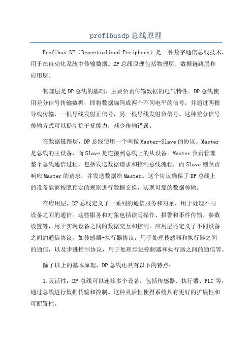
profibusdp总线原理Profibus-DP(Decentralized Periphery)是一种数字通信总线技术,用于在自动化系统中传输数据。
DP总线原理包括物理层、数据链路层和应用层。
物理层是DP总线的基础,主要负责传输数据的电气特性。
DP总线使用差分信号传输数据,即将数据编码成两个不同电平的信号,并通过两根导线传输,一根导线发射正信号,另一根导线发射负信号。
这种差分信号传输方式可以提高抗干扰能力,减少传输错误。
在数据链路层,DP总线使用一个叫做Master-Slave的协议。
Master是总线的主设备,而Slave是连接到总线上的从设备。
Master负责管理整个总线通信过程,包括发送数据请求和控制总线流程,而Slave则负责响应Master的请求,并发送数据给Master。
这个协议确保了DP总线上的设备能够按照预定的规则进行数据交换,实现可靠的数据传输。
在应用层,DP总线定义了一系列的通信服务和对象,用于处理不同设备之间的通信。
这些服务和对象包括读写操作、报警和事件传输、参数设置等,用于实现设备之间的数据交互和控制。
应用层还定义了不同设备之间的通信协议,如传感器-执行器协议,用于处理传感器和执行器之间的通信,以及步进控制协议,用于处理步进控制器和执行器之间的通信等。
除了以上的基本原理,DP总线还具有以下的特点:1.灵活性:DP总线可以连接多个设备,包括传感器、执行器、PLC等,通过总线进行数据传输和控制。
这种灵活性使得系统具有更好的扩展性和可配置性。
2.高效性:DP总线使用异步传输方式,可以同时进行多个通信过程,提高了通信效率。
此外,DP总线采用数据打包和压缩技术,减少了数据传输的开销,提高了总线的带宽利用率。
3.实时性:DP总线具有高实时性,可以在毫秒级别响应数据请求。
这对于实时控制和监测应用非常重要。
4.可靠性:DP总线采用先进的纠错技术和误码检测机制,可以确保数据的可靠传输。
PROFIBUS-DP简单概述

日期
2004/06
页数19
组态智能DP从站CPU315-2DP
日期
2004/06
页数20
将智能DP从站插入到主站系统
日期
2004/06
页数21
练习3
智能从站
日期
2004/06
页数22
日期
2004/06
页数2
现场应用的概述
PROFIBUS-FMS 主要解决车间级通信问题,完成中等传输速度的循环或非循环数据交换任 务。
PROFIBUS-DP 是一种高速(数据传输速率9.6Kbps/s~12Mbps)、经济的设备级网络, 主要用于现场控制器与分散I/O之间的通信,可满足交直流调速系统快速响 应的时间要求。
日期
2004/06
页数8
9针D型连接器的针脚分配(RS485)
日期
2004/06
页数9
日期
2004/06
页数10
日期
2004/06
页数11
日期
2004/06
页数12
日期
2004/06
页数13
日期
2004/06
页数14
日期
2004/06
页数15
组态DP主站系统
日期
2004/06
页数16
PROFIBUS-PA 传输速率为31.25Kbps,提供本质安全特性,适用于安全性要求较高以及由 总线供电的场合。
日期
2004/06
页数3
日期
2004/06
页数4
日期
2004/06
页数5
日期
2004/06
页数6
RS-485传输技术的布线和总线终端器
日期
profibusdp总线原理

profibusdp总线原理PROFIBUS-DP(Process Field Bus - Decentralized Peripherals)是一种用于分布式自动化控制系统的数字通信总线。
PROFIBUS-DP 是德国西门子公司于20世纪90年代早期推出的,已成为目前世界上使用最广泛的数字通信总线之一、下面将详细介绍 PROFIBUS-DP 总线原理。
PROFIBUS-DP 是一种半双工的串行通信系统,它能够提供480Mbps的通信速率。
PROFINET-DP 协议作为一种工业以太网,使用标准以太网物理层(10、100或1Gbps等),同时增加了实时性和对散射现场公差的支持。
PROFIBUS-DP&PROFINET-DP 以单主机和多从机的方式进行通信,它采用2线交流电源进行通信,具有高可靠性和实时性。
PROFIBUS-DP 主要由三部分组成:数据单元(Data unit)、传输单元(Transmission unit)和物理层(Physical layer)。
数据单元:数据单元是PROFIBUS-DP的核心部分,主要包括帧同步、检错和POW和CRC码生成器等功能。
它将用户数据封装成由地址、控制位、长度和内容组成的数据帧,并且对数据帧进行识别和定位,确保帧同步和完整性。
数据帧的地址用于确定目标设备的地址和呼叫方设备的地址,控制位用于指示数据帧的类型,长度字段表示数据帧的长度,而内容字段代表用户数据。
传输单元:传输单元负责帧的传输和接收,主要包括传输计时、检错以及缓冲区控制等功能。
传输单元使用异步通信方式,基本的传输速率为9600bps,并支持更高速率。
异步通信的时序控制是由传输单元中的着陆器、时钟和同步器之间的配合实现的。
传输单元还通过使用缓冲区管理机制来实现传输错误检测和纠正功能以确保数据的完整性和正确性。
物理层:物理层负责将数字信号转换为电信号,以便将信号传输到远程设备。
它靠着在两条电缆上传送电流的方式来实现数据信号的传递和电源的供应,使用橙边的电流互锁技术来抑制干扰。
PROFIBUS_DP主站和从站通讯的设计与实现
PROFIBUS_DP主站和从站通讯的设计与实现PROFIBUS_DP(Process Field Bus - Decentralized Periphery)是一种用于工业自动化领域的通信协议,主要用于连接主站(Master)和从站(Slave)之间进行高效、可靠的数据交换。
1.网络规划和布线:在设计和实施PROFIBUS_DP通信网络之前,需要进行网络规划和布线。
这包括确定主站和从站的物理位置,确定总线长度和拓扑结构,选择合适的网络线缆和连接器,并确保电缆长度、封装和终端阻抗等参数符合规范要求。
2.主站和从站选择:根据系统要求和通信需求,选择合适的PROFIBUS_DP主站和从站设备。
主站设备通常具有更强大的处理能力和更丰富的通信功能,而从站设备则主要负责执行具体的控制任务。
3.通信参数设置:在开始通信之前,需要对主站和从站的通信参数进行设置。
这包括波特率、传输速率、帧格式、地址分配等参数的配置。
主站和从站需要使用相同的通信参数才能正确地进行通信。
4.主站和从站通信协议:PROFIBUS_DP主站和从站之间的通信协议是实现通信的核心。
主站负责发送请求,从站负责响应请求并返回相应结果。
通信协议通常包括数据帧的格式和解析规则、握手和确认机制、错误处理等内容。
主站和从站需要根据PROFIBUS_DP协议规范进行开发和实现。
5.数据交换和处理:主站通过发送请求,从站接收请求并返回响应,主站接收响应,并进行数据处理。
这涉及到数据包的传输和解析,数据的读写和处理,错误的检测和恢复等。
主站和从站需要按照PROFIBUS_DP协议规范来实现数据的交换和处理。
6.系统测试和调试:在设计和实现完PROFIBUS_DP主站和从站通信之后,需要进行系统测试和调试。
这包括检查通信连接的正确性,测试通信的可靠性和稳定性,验证数据的准确性和一致性,以及排除可能存在的通信故障。
总结起来,PROFIBUS_DP主站和从站通信的设计和实现需要进行网络规划和布线、选择合适的设备、设置通信参数、实现通信协议、进行数据交换和处理,以及进行测试和调试。
PROFIBUS-DP现场总线技术
PROFIBUS-DP现场总线技术PROFIBUS-DP(Decentralized Periphery)是德国西门子(Siemens)公司于1992年发布的工业自动化现场总线协议,该协议通常用于自动化控制领域中,用于实现控制器与现场设备(如传感器、执行机构等)的通讯。
PROFIBUS-DP技术结构PROFIBUS-DP是一个基于Master/Slave的现场总线,其技术结构由Master站和Slave站组成。
Master站负责控制和管理总线上的所有Slave站,并且可以向Slave站发送指令;Slave站则负责将现场设备的状态信息发送给Master站,或根据Master站的指令进行相应的控制。
此外,PROFIBUS-DP的技术结构中还包括总线的物理层、数据链路层和应用层。
总线的物理层:PROFIBUS-DP支持RS485和光纤等多种物理媒介,其中最常用的是RS485。
数据链路层:数据链路层负责控制数据帧的传输,为数据传输提供错误检测和纠正机制。
PROFIBUS-DP的数据链路层支持多种传输速率,包括9.6kbit/s、19.2kbit/s、45.45kbit/s、93.75kbit/s和187.5kbit/s等。
应用层:应用层定义了Master和Slave之间的通讯规范和数据格式。
PROFIBUS-DP的应用层支持多种通讯方式,包括请求/响应、发布/订阅等,同时支持多种数据格式,包括二进制、十进制、浮点数等。
PROFIBUS-DP的特点1.速度快PROFIBUS-DP最高速度可达到12Mbit/s,远高于一般总线(如Modbus、CAN等)的速度。
2.可靠性高PROFIBUS-DP采用了多级校验、纠错和恢复机制,可以保障数据传输的准确性和可靠性。
3.灵活性好PROFIBUS-DP支持多种物理媒介、多种传输速率和多种通讯方式,为不同的应用场景提供了灵活的选择。
4.易于操作和维护PROFIBUS-DP的硬件和软件都是标准化的,操作和维护相对简单方便。
ProfiBus-DP总线设备及应用

HollySys 控制网CNET ProfiBus-DP 设备及应用1 前言现场总线(Fieldbus)是应用在现场、在智能化测量控制设备之间实现双向串行多接点数字通信的系统,也被称为开放式、数字化、多点通信的底层控制网络。
ProfiBus 是比较有影响的现场总线技术之一,它符合欧洲标准EN50170。
ProfiBus 根据应用特点分为ProfiBus-DP、ProfiBus-FMS、ProfiBus-PA 三种协议。
ProfiBus-DP 是经过优化的高速通信连接,专为自动控制系统和设备级分散I/O 之间通信设计。
使用P rofiBus-DP 模块可以取代价格昂贵的24V 和0~20mA 并行信号线,用于分布式控制系统的高速数据传输。
2 ProfiBus-DP 简介2. 1 ProfiBus 的基本特性ProfiBus 可使分散式数字化控制器从现场底层到车间级网络化,该系统分为主站和从站。
主站决定总线的数据通讯,当主站得到总线控制权,没有外界请求也可以主动发送信息。
从站没有总线控制权,仅对接收到的信息给予确认或当主站发出请求时向它发送信息。
ProfiBus 提供了三种类型的传输技术:DP 和FMS 的RS485 传输;PA 的IEC1158-2 传输;光纤。
RS485 是ProfiBus 最常用的一种,采用屏蔽双绞线,共用一根导线对。
RS485 为总线结构,最大总线负载32 个单位负载(UL),传输速度可选用9.6Kbps~12Mbps ,一旦设备投运,每条链路上的全部设备需设定为同一传输速率。
传输速度取决于电缆长度。
2. 2 ProfiBus-DP 的基本功能中央控制器周期地读取从设备的输入信息并周期地向从设备发送信息。
ProfiBus-DP 的基本功能如下:传输技术·RS-485 双绞线电缆或光缆·波特率9.6Kbps~12Mbps总线存取HollySys 1Profibus-DP总线设备及应用·各主站间令牌传送,主站与从站间数据传送·支持单主和多主系统·主-从设备,总线上最多站点数126通信·点对点(用户数据发送)或广播(控制指令)·循环主-从用户数据传送和非循环主-主数据传送3 ProfiBus-DP 总线在MACS TM 系统中的应用MACS TM 是和利时公司集多年的开发、工程经验设计的大型综合控制系统。
和利时现场总线系统应用探究

和利时现场总线系统应用探究摘要:选题的理论意义:由于不同的DCS厂家出于垄断经营的目的而对其控制通讯网络采用专用的封闭形式,不同厂家的DCS系统之间以及DCS与上层的Intranet、Internet之间难以实现网络互联和信息共享,因此DCS系统实质上是一种专用封闭的、不能互联的分布式控制系统,且DCS价格昂贵,用户对此提出了开放性和降低成本的迫切要求。
现场总线控制系统(FCS)正是顺应了上述的用户要求,采用了现场总线这一开放的、可互连的网络技术将现场的各种控制器和仪表设备相互连接,把控制功能彻底下放到现场,降低了安装成本和维护费用。
因此,FCS系统实质上是一种开放的、可以互连的、低成本的、彻底分散的分布式控制系统。
作为新一代控制系统:一方面:FCS突破了DCS采用专用通信网络的局限,采用了基于开放式、标准化的通信技术,克服了封闭系统所造成的缺陷;另一方面:FCS进一步变革了DCS中“集散”系统结构,形成了全分布式系统构架,把控制功能彻底下放到现场。
本论文主要分析和利时K系列现场总线控制系统中Profibus-DP和Profibus-PA协议应用,其中PROFIBUSDP数据传输速率9.6Kbps~12Mbps,PROFIBUSPA传输速率为31.25Kbps。
针对现场应用中已经解决的故障、捕捉故障现象分析根本原因,总结解决方案。
为现场总线技术在电厂中应用遇到的问题进行研究。
关-键-词:DCS控制技术;PROFIBUS现场总线;K-DP03;K-PA021 前言利用现场总线技术,把现场测量、控制设备连接成网络系统,按公开、规范的通信协议,在现场测量、控制设备之间,以及这些设备与监控计算机(或DCS控制站)之间,实现双向数据传输和信息交换,构成由现场总线测量、控制设备集成的自治式控制系统,和由现场总线测量、控制设备与监控计算机(或DCS控制站)结合在一起构成一个完整控制系统,并可通过现场总线网络对现场测量、控制设备进行实时诊断、维护的系统。