风扇产品说明书
电风扇说明书格式范文
电风扇说明书格式范文一、欢迎使用。
嗨,朋友!欢迎你把这台超棒的电风扇带回家。
它就像一个小小的清凉精灵,准备在炎热的日子里给你带来凉爽舒适的风哦。
二、外观部件介绍。
1. 扇头。
这是电风扇最重要的部分啦,就像它的大脑一样。
扇叶就在扇头里面呢,扇叶呼呼一转,风就吹出来啦。
而且扇头还可以左右摇头,这样就能把风送到更大的范围啦。
2. 支柱。
支柱就像电风扇的脊梁,它稳稳地支撑着扇头。
有的支柱还可以调节高度哦,不管你是坐在沙发上还是躺在床上,都能把风扇调整到合适的高度,让风正好吹到你身上。
3. 底座。
底座可是电风扇的根基,它又大又重,这样就能保证风扇稳稳地站在地上或者桌子上,不会轻易摔倒啦。
就像一个稳重的小胖子,虽然看起来有点笨笨的,但是作用可大着呢。
三、功能介绍。
1. 风速调节。
咱这风扇一般有好几个风速档呢。
最低档的风就像温柔的小手轻轻抚摸着你,适合在不太热的时候或者你想享受那种轻柔微风的时候用。
高档的风就比较猛啦,像一阵小旋风,在特别热的时候,打开高档,那叫一个凉快。
2. 摇头功能。
这个功能可方便啦。
只要你打开摇头功能,风扇就会像个小机器人一样,脑袋左右摆动,把风送到周围的每个角落。
这样就不用你老是手动去调整风扇的方向啦。
而且有些风扇摇头的角度还可以调节呢,是不是很厉害?3. 定时功能。
如果你担心睡觉的时候风扇一直吹会着凉,或者你只是想让风扇吹一会儿就停,这个定时功能就派上用场啦。
你可以设定30分钟、1小时、2小时等等,到了时间,风扇就会自动停止工作,就像一个听话的小跟班。
四、使用方法。
1. 组装(如果需要)如果你的风扇是需要组装的,那也很简单哦。
一般来说,只要把支柱插到底座上,然后再把扇头安装到支柱上就好啦。
不过在安装的时候要小心一点,别把零件弄坏了。
就像搭积木一样,但是这个积木搭起来可是能给你带来凉爽的呢。
2. 插电开机。
找到风扇的电源线,把它插到合适的插座上。
然后在风扇上找到电源开关,按下开关,风扇就开始工作啦。
新风扇产品说明书

Manual v1.2Evaporative CoolerAF-1000 SeriesOWNER’S MANUALRead and save these instruc tions.2A Name You Can TrustTrust should be earned and we will earn yours. Customer happiness is the focus of our business.From the factory to the warehouse, from the sales floor to your home, the whole NewAir family promises to provide you with innovative products, exceptional service, and support when you need it the most. Count on NewAir.As a proud NewAir owner, welcome to our family. There are no robots here, real people shipped your product and real people are here to help you. Contact Us:For questions regarding your product, please contact us at:Call: 1-855-963-9247Email: ******************Online: Connect with Us: /newairusa /newairusa /newairusa/newairusa3R EAD AND SAVE THESE INSTRUCTIONS.Register Your Product Online (4)Safety Information & Warnings (5)Parts List (6)Assembly & Installation (6)Installing FIlters (7)Cleaning & Maintenance (8)Troubleshooting (9)Limited Manufacturer’s Warranty (10)SPECIFICATIONSM ODEL N O. AF-1000V OLTAGE: 120/60HzC URRENT: 160WF REQUENCY: 20 LitersRegister Your NewAir Product Online Today!Take advantage of all the benefits product registration has to offer: Service and SupportDiagnose troubleshooting and service issues faster and more accuratelyRecall NotificationsStay up to date for safety, system updates and recall notificationsSpecial PromotionsOpt-in for NewAir promotions and offersRegistering your product information online is safe & secure and takes less than 2 minutes to complete:Alternatively, we recommend you attach a copy of your sales receipt below and record the following information, located on the manufacturer’s nameplate on the rear of the unit. You will need this information if it becomes necessary tocontact the manufacturer for service inquiries. Date of Purchase: ___________________________________________ Serial Number: ____________________________________________ Model Number: ____________________________________________SAFETY INFORMATION & WARNINGSWhen using any electrical appliance, basic safety precau ons must be followed in order to reduce the risk of fir e, electrical shock and/or injury to persons or property. Be sure to read all instruc ons before using this appliance and observe the following safety tips:•Carefully read all instruc ons before use.•Check the condi on of the unit a er taking it out of the box. Ensure that all parts are in good condi on.•Before using the unit, verify that the cooler’s voltage requirements correspondwith your power outlet.• Do not use any appliance with a damaged cord or plug. If the cord is damaged, please contact an authorized service center.• Do nempt to repair, adjust, or replace parts in the unit. Any repairs must be made by an authorized technician. • Do not place the unit near gas or electric stoves.• Cau on should be taken when the cooler is used near children. The unit shouldnot be le un ended for any extended period of m e whie in operation.• This appliance should not be used by persons (including children) with reducedphysical, sensory, or mental capabili es, or lack of experience and knowledge,unless they have been given supervision or instruc on concerning its use by a person responsible for their safety.•This unit is intended for household indoor use. Do not operate thi s evaporative cooler in bathrooms or in any other wet or damp loca ons. • Do not insert objects into the air louvers.•Use the “Power” bun to turn the unit on or o ff. Do not contro l operation by pulling the plug from the power outlet.• To prevent the risk of electric shock, do not operate the unit with wet hands. •Save this instruc on manual for future reference.WARNING: TO Reduce The Risk Of Fire Or Electric Shock, Do Not Use This Fan With Any Solid-State Speed Control Device.WARNING :The cells shall be disposed of properly, including keeping them away from children, even used cells may cause injury.PARTS LISTASSEMBLY & INSTALLATION1. POWER: Connect the cord to a power outlet. An indicator light willturn on, indicating that the power source is connected. Press the “On/Speed” button to turn the unit on. When it turns on, the cooler will start at medium speed (number 2) and then drop to the low speed setting (number 1) after a few seconds.2. SPEED: To adjust the fan speed, press the “On/Speed” buttonrepeatedly until the desires speed appears on the display.1. Control Panel2. Air Louvers3. Carrying Handles4. Cord Wrap5. Honeycomb Filter6. Partition7.Carbon Filter8. Dust Filter & RearScreen9. Water LevelIndicator 10. Casters11. Water Tank 12. Drain Hole13.Remote Control•Low Speed•Medium Speed•High Speed3.OSCILLATION: To turn on the oscillation feature, press the “OSC”button once. The indicator will appear on the display. Press the “OSC”button again to turn off the oscillation feature.4.TIMER: The unit comes with a 10-hour timer (max. 10 hours). To setthe timer, press the “Timer” button. Each time the “Timer” button ispressed, 0.5 hour of operation time is added. To have the unit runcontinuously, make sure the timer is off.•Press once – 0.5 hour•Press twice – 1 hour•Press 3 times – 1.5 hours•Up to 10 hours5.COOLING: Fill the tank with water and press the “COOL” button. Theindicator light will turn on. To stop the unit from cooling, press thebutton again.6.ADDING WATER TO THE TANK: Follow these steps to add water to thewater tank:•Pull off the water tank’s cover.•Carefully pour water into the water tank.•Do not exceed the “maximum” water line on the water level indicator.•For enhanced cooling, add ice to the tank. INSTALLING FILTERS1.Remove the two included filters from their packaging.2.Unscrew the rear screen and install the two filters so that they arenearest to the rear screen, not the front of the unit. The order thefilters are installed does not matter.3.Close the rear screen and screw it back in.4.Add water as mentioned in the previous section and your evaporativecooler is now ready to use.CLEANING & MAINTENANCE1.Before disassembling the unit, unplug the unit from the power outletand drain all of the water from the tank by removing the drain cap.e a clean, damp cloth to wipe away any dust or dirt from the unit’sexterior. Also wipe down the air louvers.3.CLEANING THE DUST FILTER: Clean the dust fil ter by unscrewing/pulling out the dust fil ter and washing the dust fil ter with runningwater.4.CLEANING THE HONEYCOMB FILTER AND TANK: Clean thehoneycomb fil ter and tank by following these steps:•Unscrew and pull out the dust fil ter.•Clean the honeycomb fil ter by using a vacuum or brush.•Use a damp cloth with soap to clean and remove any residue from the water tank.•Rinse and drain the water tank.•Replace the honeycomb and dust filt ers back into the unit.Make sure the fil ters are properly inserted before ti ghteningthe screws.NOTE: We recommend cleaning the unit every 3 months with regular use. However, if you have hard water with a high mineral content, we recommend cleaning the unit once a month to prevent residue builduph tt p://TROUBLESHOOTINGThe unit produces no air. The unit is not pluggedin.Check to make sure the plugis plugged into an outlet.The unit should beep twiceonce the power supply isconnected.The water tank is notlocked into the unit.Make sure the water tank islocked into the back of theunit.The unit does not cool.There is insufficientwater in the tank.Check the water level in thetank and make sure there isenough water.The cooler/humidifierbutton was notpressed.Press the COOLER/HUMIDIFER button.The pump is defective. Contact customer service ifthere is an issue with thewater pump.The unit does not cool on high speed.The cooling pad is notsufficiently saturatedwith water.If speed 3 is selected whenin cooling mode, the unit willautomatically revert tospeed 2 for 5 minutes toallow the pad to be fullysoaked. The cooler willautomatically turn to speed3 when the pad is soaked.Water is coming out of the vents.The cooling pad may beclogged with debris.Clean the cooling pad byrinsing it in water andallowing it to thoroughly dry.You can also clean it with awater and vinegar solution.If the problem persists,contact customer service.LIMITED MANUFACTURER’S WARRANTYThis appliance is covered by a limited manufacturer’s warranty. For one year from the original date of purchase, the manufacturer will repair or replace any parts of this appliance that prove to be defective in materials and workmanship, provided the appliance has been used under normal operating conditions as intended by the manufacturer.Warranty Terms:During the first year, any components of this appliance found to be defective due to materials or workmanship will be repaired or replaced, at the manufacturer’s discretion, at no charge to the original purchaser. The purchaser will be responsible for any removal or transportation costs. Warranty Exclusions:The warranty will not apply if damage is caused by any of the following: •Power failure•Damage in transit or when moving the appliance•Improper power supply such as low voltage, defective household wiring or inadequate fuses•Accident, alteration, misuse or abuse of the appliance such as using non-approved accessories, inadequate air circulation in the room orabnormal operating conditions (extreme temperatures) •Use in commercial or industrial applications•Fire, water damage, theft, war, riot, hostility or acts of God such as hurricanes, floods, etc.•Use of force or damage caused by external influences•Partially or completely dismantled appliances•Excess wear and tear by the userObtaining Service:When making a warranty claim, please have the original bill of purchase with the purchase date available. Once confirmed that your appliance is eligible for warranty service, all repairs will be performed by a NewAir™ authorized repair facility. The purchaser will be responsible for any removal or transportation costs. Replacement parts and/or units will be new, re-manufactured or refurbished and is subject to the manufacturer’s discretion. For technical supportandwarrantyservice,********************************.。
电风扇使用说明书

非常感谢选购本公司的产品,请仔细阅读本使用说明书,以便正确地使用本产品。
阅读后请保留作日後參考之用。
※本产品有部份需要由客户自己组装。
本使用說明書之圖片只供參考,實際以廠方生產的規格為準。
●为保证您正确使用本产品,使用前请务必仔细阅读本“安全相关注意事项”。
本注意事项中记载了与安全相关的重要性内容,请必须严格遵守。
为方便您随时取阅,阅读完毕后请务必妥善保管。
图示符号的意思及实例■司此產品不適合身體、感官或精神功能遲緩,或缺乏經驗與知識的人(包括兒童)使用,除非他們在負責其安全的人的監督或指引下使用。
■司請看管好兒童,確保他們不會以本產品玩耍。
■司本電器只可使用隨附的電源裝置。
■司本電器必須使用對應本電器上的標記的安全特低電壓。
您购买后,请确认以下配件。
组装后本产品的包装材料请不要棄掉,使用季节过后,产品收纳起来时可以存储本产品。
底座部.......................................................... 1 个本休机头部 (带香薰盒盖)......................... 1 个中支管.......................................................... 1 个专用AC适配器..............................................1 个遥控器.......................................................... 1 个硬币形锂电池(CR2025 单独胶袋包装...... 1 个香薰棉(香薰盒内装1个)........................... 1 个说明书(包含保修卡) ................................ 1 个包装清单请在水平稳定的地面使用本產品。
2.请使用专用 AC 适配器① 请将 AC 适配器的 DC 插头插进底盘后面的DC 插孔里。
飞利浦 3000系列 电风扇(冷风扇) 使用手册说明书

ACR3142C3 功能特点3••••••冷风加湿原理:利用水泵将水箱中冷水抽到机体顶部后经过湿帘纸流下,再由转动的风轮把湿帘纸周围具有一定湿度的冷空气吹出;因为水份蒸发吸热,从而达到降低温度和加湿功能。
电子式控制:本机具有电子式控制功能,安全耐用,外型美观。
风速、风类可调:三档风速,三种风类设计,送风量大,在炎热的夏季可为您带来舒适的生活环境。
并可实现左右、上下送风。
负离子,健康好生活:采用负离子发生技术,在工作的同时释放大量负离子,清新空气,强力杀菌。
冷风增湿功能:本机采用冰晶制冷和空气加湿技术,可降低出风口空气温度和提高空气相对湿度,防止空气干燥。
抽拉式水箱,可拆卸式湿帘纸,清洗方便:采用抽拉式水箱,不漏水,防止细菌滋生。
可拆卸式湿帘纸,用中性的清洗剂和软毛刷即可轻松清洗干净。
••••广角送风:自动横摆页和竖摆页,风向可自动水平上下和左右广角送风。
远距离遥控功能:5 米远距离遥控,60° 大角度接收。
键控蜂鸣提示功能:对有效的按键操作进行蜂鸣提示,使用方便。
水泵无水情况下防空转干烧功能:在水箱中安装了水位开关,时时监控水箱内的水位情况,无水时发出“嘀··嘀”报警声;防止水泵在无水状态下空转干烧。
1 24加水方法4打开包装箱取出冷风扇,将冷风扇放在水平地面上;检查包装箱内零件是否与说明书内装箱单相符。
注意:冰晶盒放置于纸箱内泡沫中。
加水:从机体背部下方拉出水箱,使水箱外露 1/3 ,向水箱中加入清洁的自来水即可。
(图1)注意:a . 加水时请先拔掉电源插头。
b . 加水时请注意冷风扇水位窗上的 “水位显示”。
(图2)c . 加水时注意水箱水位不可超过“MAX ”(最高)指示刻度。
冷风加 湿时,应控制水箱的总水位不可低于 “MIN ”(最低)指示刻度。
d . 如欲加强降温效果,可将冰或经过冷 冻的冰晶盒放在机体内的水箱中。
(警告:加入冰或冰晶盒后,水箱总 水位不可超过“MAX ”最高指示刻 度)。
无叶风扇说明书
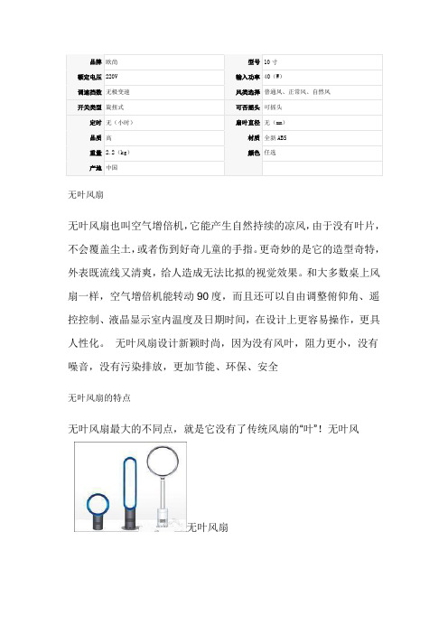
无叶风扇无叶风扇也叫空气增倍机,它能产生自然持续的凉风,由于没有叶片,不会覆盖尘土,或者伤到好奇儿童的手指。
更奇妙的是它的造型奇特,外表既流线又清爽,给人造成无法比拟的视觉效果。
和大多数桌上风扇一样,空气增倍机能转动90度,而且还可以自由调整俯仰角、遥控控制、液晶显示室内温度及日期时间,在设计上更容易操作,更具人性化。
无叶风扇设计新颖时尚,因为没有风叶,阻力更小,没有噪音,没有污染排放,更加节能、环保、安全无叶风扇的特点无叶风扇最大的不同点,就是它没有了传统风扇的“叶”!无叶风无叶风扇[1]扇利用喷气式飞机引擎及汽车涡轮增压中的技术,通过底部的吸风孔吸入空气,圆环边缘的内部隐藏的一个叶轮则把空气以圆形轨迹喷出,最终形成一股不间断的冷空气流。
重要的是这种空气流动比普通风扇产生的风更平稳。
它产生的空气量相当于目前市场上性能最好的风扇。
因为没有风扇片来…切割‟空气,你不会感到冲击和刺激。
它通过持续的空气流让你感觉凉爽。
这款无叶风扇同时带有变频风速大小调节装置,方便用户根据实际情况调节风速的大小,风量均匀增加,不会冲击电压,能耗低,是普通风扇一半能耗。
因为没有风叶,这种风扇不仅看起来更酷,而且比传统风扇更安全,同时摇头、风速控制等功能也与后者不相上下。
无叶风扇的起源无叶风扇于2009年10月12日在英国首度推出,这项发明的灵感源于空气无叶风扇叶片干手器。
空气叶片干手器的原理是迫使空气经过一个小口来“刷”干手上的水,空气增倍机是让空气从一个1.3毫米宽、绕着圆环转动的切口里吹出来。
由于空气是被强制从这一圆圈里吹出来的,通过的空气量可增到15倍,它的时速可增至35公里。
空气增倍机的空气流动比普通风扇产生的风更平稳。
它产生的空气量相当于目前市场上性能最好的风扇。
因为没有风扇片来…切割‟空气,使用者不会感到阶段性冲击和波浪形刺激。
它通过持续的空气流让你感觉更加自然的凉爽。
” 无叶风扇的原理无叶风扇的工作原理为:基座中带有的40瓦电力马达每秒钟将33升的无叶风扇空气吸入风扇基座内部,经由气旋加速器加速后,空气流通速度最大被增大16倍左右,经由无叶风扇扇头环形内唇环绕,其环绕力带动扇头附近的空气随之进入扇头,并以每秒405升的速度向外吹出。
荣事达三洋电器 FD30-436D FD30-436Y电风扇产品 说明书
电风扇产品使用说明书型号:FD30-436D、FD30-436Y目录功能与特点 2 主要技术指标 2 安装说明 2 结构图 3 清洁与贮存 4 特别注意事项 4 使用说明 5 遥控器操作的注意事项 6 遥控器电池的更换方法 6 电路图7 保修卡7●使用前请仔细阅读本说明书●请注意保存1功能与特点该豪华电风扇是采用国际先进的技术及新颖设计而成的家用乘凉电器,它不仅外观美丽、大方、简洁,且设置了IC程序控制、遥控负离子空气净化等功能,并能根据需要调节高度,具有功能耗低,超静音,风量大等优点。
主要技术指标规格:300mm额定电压:AC220V额定频率:50Hz额定功率:45W摇头角度:65°高度调节:1085~825 mm安装说明1.将基座杆插入基座中,同时基座杆的▲标记与基座的▼标记对齐,并用锁紧环紧固。
2.取下机头上的风帽与锁紧环。
3.将后网罩(提手向上)嵌入电机前罩,同时后网罩的凹部对准电机前罩的凸起处,再用锁紧环紧固后网罩。
4.将扇叶中心孔对准电机轴推入,然后用风帽逆时针拧入紧固扇叶。
5.松开前网罩上的锁紧装置,然后前网罩挂扣扣准后网罩上中点后从上向下卡入后网罩。
6.用前网罩锁紧装置锁定前后网罩。
2结构图3清洁与贮存1.电风扇清洁前,务必切断电源并拔出电源线插头。
2.按组装相反之程序拆下电风扇零部件。
3.用棉质软布及非溶剂清洁剂除去零部件表面污渍。
切勿用汽油、松香水、去污粉、碱性洗涤剂擦洗风扇,否则会使风扇变色、变形、开裂。
4.切勿将电扇置于水中清洗。
5.电风扇长期不用时,需将风扇表面弄干后包装好,置于干燥环境中贮存。
特别注意事项1.为确保安全,请于安装、使用前认真阅读说明书。
2.开启产品包装后,检查有无异样。
3.勿将包装件留给小孩和老弱病残者。
4.连接电源前,检查使用电源是否与电风扇规格相符。
5.尽量避免使用附加多联插座和加长线。
如有必要该零件必须与电风扇使用安全规定相符。
6.该电风扇仅限于室内使用,避免浴室使用。
便携迷你折叠小风扇说明书

便携迷你折叠小风扇说明书
一、概述
AI 智能风扇是一款高灵敏度智能视觉摄像采集人脸、人形识别,搜索其所在位置,在采集搜索位置过程中风速是最小的。
当搜索到准确位置时,进行小幅度的摆动设备,风扇根据人物的与其的距离远近自动调节风速。
二、产品特性
材质:铝合金&ABS 塑料
供电方式:内置 18650 锂电池供电
功率:1.3至4.8W
噪音分贝:30至40db
电压/电流:5V,2A
风速:2.3至4.0 m/S
电芯:电池容量 7200mAh, 3.7V
充满电约 4 小时左右,待机时间 6~12 小时,使用时间 2~4 小时。
三、使用说明
1、开关键
拨动开关键位置,拨向 ON 是开启风扇,拨向 OFF 是关闭风扇。
2、电源输入口
电源接口电源使用 USB 接口 5V/2A 进行充电,充电时指示灯会依次亮,充满电时指示灯全亮。
3、OPEN 标识
折叠状态下,在“OPEN”处向上拉开,然后打开风扇
四、包装配件
AI 智能风扇一台;充电线一条;使用说明书一份。
五、注意事项
使用前请先将本产品充满电。
本产品内置充电锂电池,废弃时请不要污染环境,尽量分类回收利用。
本产品应经常使用,如长时间不使用时,需要存放 2 个月充电一次,每次充电至少 2 小时,否则会降低电池寿命。
禁止拉伸,以免损坏线路连接。
请勿过度调节产品的活动关节或支撑杆,以免损坏产品。
jimmy电风扇说明书

jimmy电风扇说明书Jimmy电风扇说明书一、产品介绍Jimmy电风扇是一款高品质的家用电器,拥有强大的风力和静音设计,为用户带来舒适的风扇体验。
本说明书将为您详细介绍Jimmy 电风扇的特点、使用方法和注意事项。
二、产品特点1. 强力风力:Jimmy电风扇采用高效电机和扇叶设计,能够产生强劲的风力,快速带走炎热和闷热。
2. 静音设计:Jimmy电风扇采用先进的静音技术,减少噪音干扰,让您在享受清凉的同时保持宁静。
3. 多档风速:Jimmy电风扇拥有多档风速调节,可根据需要选择合适的风力,满足不同场景的使用需求。
4. 宽角摆风:Jimmy电风扇具有宽广的摆风角度,能够将凉风均匀地送到每一个角落,使整个房间都能感受到凉爽。
5. 定时功能:Jimmy电风扇配备定时功能,可根据个人需求,设置自动关闭时间,方便夜间使用和节约能源。
三、使用方法1. 插上电源:将电风扇的插头插入电源插座,确保电源稳定。
2. 打开电源开关:将电风扇上的电源开关调到“开”位,此时电风扇开始工作。
3. 调节风速:根据个人需求,选择合适的风速档位。
旋转电风扇上的风速调节钮即可调整风力大小。
4. 调整摆风角度:按下电风扇上的摆风按钮,电风扇将开始左右自动摆风。
如需固定风向,可手动调整风扇头部角度。
5. 设置定时关闭:如需使用定时功能,按下电风扇上的定时按钮,根据提示设置自动关闭时间。
四、注意事项1. 使用时请确保电源插座连接牢固,避免松动或触电风险。
2. 使用过程中请勿将手指或其他物体伸入电风扇进风口或出风口,以免发生意外。
3. 使用定时功能时,请合理设置自动关闭时间,避免浪费电能。
4. 使用前请仔细阅读本说明书,并按照说明进行正确操作。
5. 在清洁电风扇之前,请先将电源切断,并等待电风扇完全停止工作。
6. 清洁电风扇时,请使用干布或软刷清除风扇表面的灰尘,切勿使用水直接清洗。
7. 如遇到故障或异常情况,请立即切断电源并联系售后服务中心。
30英寸濒水平风扇产品说明书

30 InchMisting Pedestal FanOwner’s ManualWARNING:Item #63668Thank you very much for choosing a Strongway®product!For future reference, please complete the owner’s record below:Serial Number/LotDate Code: ________________________________ Purchase Date: ____________________________________________ Save the receipt, warranty, and this manual. It is important that you read the entire manual to become familiar with this product before you begin using it.This fanis designed for certain applications only. Northern Tool and Equipment is not responsible for issues arising from modification or improper use of this product such as an application for which it was not designed. We strongly recommend that this product not be modifiedand/or used for any application other than that for which it was designed. For technical questions, please call 1-800-222-5381.Table of ContentsIntended Use (4)Packaging Contents (4)Technical Specifications (5)Important Safety Information (5)Specific Operation Warnings (6)Grounding (7)Extension Cords (8)Main Parts of Fan (9)Parts List (9)Assembly Instructions (9)Before Each Use (13)Operating Instructions (13)After Each Use (14)Maintenance (14)Troubleshooting (16)Parts Diagram (17)Parts List (17)Replacement Parts (17)Limited Warranty (18)Intended UseThe Strongway 30 Inch Misting Pedestal Fan is ideal for home, garages, workshops, greenhouses, garden areas, and other areas needing a misting fan.Packaging ContentsTechnical SpecificationsProperty SpecificationMotor 120Volt AC / Direct DriveDiameter 30”Airflow 7200 CFMMax Current Consumption 2.0 AmpsMax Working Pressure N/AImportant Safety Information•Read and understand all instructions. Failure to follow all instructions may result in serious injury or property damage.•The warnings, cautions, and instructions in this manual cannot cover all possible conditions or situations that could occur. Exercise common sense and caution when using this tool. Always be aware of the environment and ensure that the tool is used in a safe and responsible manner.•Do not allow persons to operate or assemble the product until they have read this manual and have developed a thorough understanding of how it works.•Do not modify this product in any way. Unauthorized modification may impair the function and/or safety and could affect the life of the product. There are specific applications for which the product was designed.•Use the right tool for the job. DO NOT attempt to force small equipment to do the work of larger industrial equipment. There are certain applications for which this equipment was designed. This product will be safer and do a better job at the capacity for which it was intended. DO NOT use this equipment for a purpose for which it was not intended.•Industrial or commercial applications must follow OSHA requirements.WORK AREA SAFETY•Inspect the work area before each use. Keep work area clean, dry, free of clutter, and well-lit.Cluttered, wet, or dark work areas can result in injury. Using the product in confined work areas may put you dangerously close to cutting tools and rotating parts.•Do not use the product where there is a risk of causing a fire or an explosion; e.g., in the presence of flammable liquids, gases, or dust. The product can create sparks, which may ignite theflammable liquids, gases, or dust.•Keep children and bystanders away from the work area while operating the tool. Do not allow children to handle the product.•Be aware of all power lines, electrical circuits, water pipes, and other mechanical hazards in your work area. Some of these hazards may be hidden from your view and may cause personal injury and/or property damage if contacted.PERSONAL SAFETY•Stay alert, watch what you are doing, and use common sense when operating the tool. Do not use the tool while you are tired or under the influence of drugs, alcohol, or medication. A moment of inattention while operating the tool may result in serious personal injury.•Dress properly. Do not wear loose clothing, dangling objects, or jewelry. Keep your hair, clothing and gloves away from moving parts. Loose clothes, jewelry, or long hair can be caught in moving parts. Air vents on the tool often cover moving parts and should be avoided.•Wear the proper personal protective equipment when necessary. Use ANSI Z87.1 compliant safety goggles (not safety glasses) with side shields, or when needed, a face shield. Use a dust mask in dusty work conditions. Also use non-skid safety shoes, hardhat, gloves, dust collection systems, and hearing protection when appropriate. This applies to all persons in the work area.•Do not overreach. Keep proper footing and balance at all times.⚠CAUTIONFANUSE AND CARE•Do not force the fan. Products are safer and do a better job when used in the manner for which they are designed. Plan your work, and use the correct product for the job.•Check for damaged parts before each use. Carefully check that the product will operate properly and perform its intended function. Replace damaged or worn parts immediately. Never operate the product with a damaged part.•Do not use a product with a malfunctioning switch. Any power tool that cannot be controlled with the power switch is dangerous and must be repaired by an authorized service representative before using.•Disconnect the power/air supply from the product and place the switch in the locked or off position before making any adjustments, changing accessories, or storing the tool. Such preventive safety measures reduce the risk of starting the tool accidentally.•Store the fan when it is not in use. Store it in a dry, secure place out of the reach of children.Inspect the tool for good working condition prior to storage and before re-use.•Use only accessories that are recommended by the manufacturer for use with your product.Accessories that may be suitable for one product may create a risk of injury when used withanother tool. Never use an accessory that has a lower operating speed or operating pressure than the tool itself.•Keep guards in place and in working order. Never operate the product without the guards in place. •Do not leave the tool running unattended.Specific Operation Warnings•To prevent serious injury or property damage, read and understand owner’s manual before operating.•Electric shock hazard. Do not expose the unit or the plug to water or rain. Do not use the fan neara water source such as a swimming pool, bathtub, or shower.•Be sure the fan is properly grounded.•Do not use this fan with any solid-state speed control device.•Only plug the unit into a power outlet with the same voltage as rated voltage of it.•Rotating blade hazard. Keep hands clear to avoid serious injury.•Do not operate in the presence of explosive and/or flammable fumes.•Always disconnect the power before servicing and cleaning or moving the fan to a new location. •Do not plug/unplug the fan into/from the electrical outlet while wet or standing in a wet or damp area.•Never operate the fan without the guard in place.•For indoor use only. Do not use outdoors. Do not place the fan in or near a window. Rain may create an electrical hazard.•Do not operate any fan with a damaged cord or plug. Discard fan or return to an authorized service facility for repair before resuming operation.•Do not run cord under carpeting. Do not cover cord with throw rugs, runners, or similar coverings. •Do not place cord under furniture or appliances. Arrange cord away from a higher traffic area and where it will not be tripped over.Grounding•This machine must be grounded while in use to protect the operator from electrical shock. This unit is equipped with an electrical cord that has an equipment grounding conductor and agrounding plug. The plug MUST be plugged into a matching receptacle that is properly installed and grounded in accordance with ALL local codes and ordinances.•DO NOT MODIFY THE PROVIDED PLUG. If it will not fit the receptacle, have the proper receptacle installed by a qualified electrician.•CHECK with a qualified electrician or service person if you do not completely understand the grounding instructions, or if you are not sure the tool is properly grounded.Grounded Tools: Tools with 3-Prong PlugsTools marked with Grounding Required have a 3-wire cord and 3-prong grounding plug. The plug must be connected to a properly grounded outlet. If the tool should electrically malfunction or break down, grounding provides a low resistance path to carry electricity away from the user, reducing the risk of electric shock. (See Figure A.)The grounding prong in the plug is connected through the green wire inside the cord to the grounding system in the tool. The green wire in the cord must be the only wire connected to the tool’s grounding system and must never be attached to an electrically live terminal.Your tool must be plugged into an appropriate outlet, properly installed and grounded in accordance with all codes and ordinances. The plug and outlet should look like those in the following illustration.Extension Cords⚠WARNING•USE A PROPER EXTENSION CORD. Make sure your extension cord is in good condition. When using an extension cord, be sure to use one heavy enough to carry the current your product will draw. An undersized cord will cause a drop in line voltage, resulting in loss of power and cause overheating.•Be sure your extension cord is properly wired and in good condition. Always replace a damaged extension cord or have it repaired by a qualified person before using it. Protect your extension cords from sharp objects, excessive heat and damp or wet areas.•Grounded tools require a 3-wire extension cord. Double Insulated tools can use either a 2- or 3-wire extension cord.•As the distance from the supply outlet increases, you must use a heavier gauge extension cord.Using extension cords with inadequately sized wire causes a serious drop in voltage, resulting in loss of power and possible tool damage.•The smaller the wire’s gauge number, the greater the capacity of the cord. For example, a 14-gauge cord can carry a higher current than a 16-gauge cord. Minimum extension cord wire size is shown in the following table:Minimum Wire Size Of Extension CordsNameplate AMPSCord Length25' 50' 100' 150'0-6 18 AWG 16 AWG 16 AWG 14 AWG6-10 18 AWG 16 AWG 14 AWG 12 AWG10-12 16 AWG 16 AWG 14 AWG 12 AWG12-16 14 AWG 12 AWG NOT RECOMMENDED •When using more than one extension cord to make up the total length, make sure each cord contains at least the minimum wire size required.•If you are using one extension cord for more than one tool, add the nameplate amperes and use the sum to determine the required minimum cord size.•If you are using an extension cord outdoors, make sure it is marked with the suffix W-A (W in Canada) to indicate it is acceptable for outdoor use.•Make sure your extension cord is properly wired and in good electrical condition. Always replacea damaged extension cord or have it repaired by a qualified electrician before using it. •Protect your extension cords from sharp objects, excessive heat, and damp or wet areas.Main Parts of FanParts ListPart No. Description Quantity1 Misting Device 12 Front Guard 13 Blade 14 Rear Guard 15 Motor 16 Power Cord with GFCI plug 17 Upper Pole 18 Spring 19 Lower Pole 110 Base 1Assembly Instructions1. Insert five screws (2) through the holes in the standing pole (1) and then attach the standing poleto the base (3).2. Loosen and remove the three screws (1) on the height, adjusting base on the upperconnectingpole (2). Place the spring(4) into the standing pole(4). Insert the upper connecting pole(2) into thestanding pole (4), making sure the holes on the height adjusting base and the standingpole (4) arealigned. Insert the three screws (1) into the standing pole (4) and tighten them. Adjust theheight of the upper connecting pole (2) as desired and secure using the adjusting knob.3. Insert a bolt (5) into the hole on the neck bearing (found on the motor) and into thetop of theupper connecting pole. Secure them together using a bushing (1) anda nut (2). Insert one bolt (6) through the hole in the neck bearing and into the top of theupper connecting pole and secure them using a bushing (4) and a nut (3).4. Remove four sets of hexagonal nuts, spring washers, and big washers from the motor.Save themfor step 5.5. Attach the rear guard (4) to the screws found on the motor and secure them together usingfourbowl washers (1), four spring washers (2), and four nuts (3) from step 4.6. Attach the blade (2) to the shaft on the motorand secure them together using two screws (1).7. Attach the front guard (1) to the rear guard (2) and secure them together using the clips onthefront guard.8. Secure the assembly on the front and rear guard by tightening the screw(1) and nut(2) onthebottom of them.9. Connect the misting switch (1) to the water pipe (2) and tighten it. Turn the switch (open) to openthe misting function. Turn the switch (close) to close the misting function.Before Each UsePlace the fan on a safe, flat surface where it cannot fall or be pulled by the cord.Operating Instructions⚠WARNING•Electric shock hazard. Do not expose the unit or the plug to water or rain. Do not use the fan neara water source such as a swimming pool, bathtub, or shower.•Be sure the fan is properly grounded.•Do not use this fan with any solid state speed control device.•Only plug the unit into a power outlet with the same voltage as rated voltage of it.•Rotating blade hazard. Keep hands clear to avoid serious injury.•Do not operate in the presence of explosive and/or flammable fumes.•Do not plug/unplug the fan into/from the electrical outlet while wet or standing in a wet or damp area.•Never operate the fan without the guard in place.•Do not place the fan in or near a window. Rain may create an electrical hazard.•Do not operate any fan with a damaged cord or plug. Discard fan or return to an authorized service facility for repair before resuming operation.•Do not run cord under carpeting. Do not cover cord with throw rugs, runners, or similar coverings.•Do not place cord under furniture or appliances. Arrange cord away from a higher traffic area and where it will not be tripped over.1. Plug the fan into an electrical outlet.2. Pull power chain once to operate the low speed. Allow it to run for 10 seconds. Once 10 secondshave passed, pull the power chain to the medium or high position.AfterEach UseAlways turn off (0-Off) and unplug the fan after using.MaintenanceMaintain your fan. It is recommended that the general condition of any fan be examined before it is used. Keep your fan in good repair by adopting a program of conscientious repair and maintenance in accordance with the recommended procedures found in this manual.1. Depending on the usage, a regularly scheduled inspection should be established.2. Check for unusual noises when the fan is running.3. Periodically inspect and tighten all bolts, screws, and set screws.Misting Nozzle Maintenance•If the misting nozzles become clogged, remove them from grill and washthem by water. Use a non-metallic brush to scrub them if necessary, if theobstacle still exists, use the replacement nozzle or contact the customerservice for assistance. Never Clear the nozzles with pins or other sharpMisting Hose Walve Maintenance•If the misting hose walve becomes clogged, unscrew it from the gardenhose, flush it with running water to remove obstacles and debris, make surethe fillter washer is clean and well.TroubleshootingUse the table below to troubleshoot problems before contacting service personnel or your local dealer. If the problem continues after troubleshooting, call your local dealer for assistance.Symptom Possible Cause(s) Corrective ActionFan fails to operate Fan may not be plugged in.Make sure the fan is pluggedinand electrical outlet isworkingproperly.There may be some obstructions in thefan.Check for any obstruction. Ifyoufind an obstruction, turnthefanOFF. Unplug the fanandcarefully remove theobstruction.Plug the fan in andturn it onagain, referring to theoperationssection.Excessive vibration Nuts mounting motor to rear guard aretorqued insufficiently.Torque the nuts to 35-40 in. lb.Propeller imbalance due toaccumulation of dirt and debris.Clean propeller.Parts DiagramParts ListReference Part Number Part Description Quantity1 1 Misting Device 12 2 Front Guard 13 3 Blade 14 4 Rear Guard 15 5 Motor 16 6 Power Cord with GFCI Plug 17 7 Upper Pole 18 8 Spring 19 9 Lower Pole 110 10 Base 1Replacement Parts•For replacement parts and technical questions, please call Customer Service at 1-800-222-5381. •Not all product components are available for replacement. The illustrations provided are a convenient reference to the location and position of parts in the assembly sequence.•When ordering parts, the following information will be required: item description, item model number, item serial number/item lot date code, and the replacement part reference number. •The distributor reserves the rights to make design changes and improvements to product lines and manuals without notice.Limited WarrantyNorthern Tool and Equipment Company, Inc. ("We'' or "Us'') warrants to the original purchaser only ("You'' or "Your") that the Strongway product purchased will be free from material defects in both materials and workmanship, normal wear and tear excepted, for a period of one yearfrom date of purchase. The foregoing warranty is valid only if the installation and use of the product is strictly in accordance with product instructions. There are no other warranties, express or implied, including the warranty of merchantability or fitness for a particular purpose. If the product does not comply with this limited warranty, Your sole and exclusive remedy is that We will, at our sole option and within a commercially reasonable time, either replace the product or product component without charge to You or refund the purchase price (less shipping). This limited warranty is not transferable.Limitations on the WarrantyThis limited warranty does not cover: (a) normal wear and tear; (b) damage through abuse, neglect, misuse, or as a result of any accident or in any other manner; (c) damage from misapplication, overloading, or improper installation; (d) improper maintenance and repair; and (e) product alteration in any manner by anyone other than Us, with the sole exception of alterations made pursuant to product instructions and in a workmanlike manner.Obligations of PurchaserYou must retain Your product purchase receipt to verify date of purchase and that You are the original purchaser. To make a warranty claim, contact Us at 1-800-222-5381, identify the product by make and model number, and follow the claim instructions that will be provided. The product and the purchase receipt must be provided to Us in order to process Your warranty claim. Any returned product that is replaced or refunded by Us becomes our property. You will be responsible for return shipping costs or costs related to Your return visit to a retail store.Remedy LimitsProduct replacement or a refund of the purchase price is Your sole remedy under this limited warranty or any other warranty related to the product. We shall not be liable for: service or labor charges or damage to Your property incurred in removing or replacing the product; any damages, including, without limitation, damages to tangible personal property or personal injury, related to Your improper use, installation, or maintenance of the product or product component; or any indirect, incidental or consequential damages of any kind for any reason.Assumption of RiskYou acknowledge and agree that any use of the product for any purpose other than the specifieduse(s) stated in the product instructions is at Your own risk.Governing LawThis limited warranty gives You specific legal rights, and You also may have other rights which vary from state to state. Some states do not allow limitations or exclusions on implied warranties or incidental or consequential damages, so the above limitations may not apply to You. This limited warranty is governed by the laws of the State of Minnesota, without regard to rules pertaining to conflicts of law. The state courts located in Dakota County, Minnesota shall have exclusive jurisdiction for any disputes relating to this warranty.Distributed by:Northern Tool & Equipment Company, Inc.Burnsville, Minnesota 55306Made in China。
米家 智米电风扇 1X 用户手册说明书

47581169102包装清单 1电机+支柱3底座扇叶旋钮底座螺栓风扇罩螺丝7号干电池内六角扳手电源线遥控器风扇组件风扇罩旋钮Wi-Fi 指示灯支柱底座电源线接口开关机/模式切换按键开关机/模式切换按键定时关机按键定时关机按键摆头控制按键摆头控制按键风量调节按键风量调节按键状态指示灯底座螺栓产品介绍使用 6 内六角扳手,顺时针拧紧 7 底座螺栓,使支柱与底座固定。
将 7 底座螺栓插入底座底部的孔位。
安装取出风扇组件,如下图 1 逆时针旋转风扇格栅至松动,按 2 方向向外卸下风扇格栅,取出扇叶。
打开风扇组件按图示方向将 1 电机和支柱与 3 底座插口对位,将支柱下端插入底座插口。
安装底座2风扇组件121314风扇格栅扇叶风扇后罩1231将 8 风扇罩螺丝插入风扇罩底部的孔位,使用十字螺丝刀顺时针拧紧。
安装安装风扇后罩注意事项警告将风扇格栅嵌入风扇后罩边框,顺时针旋转风扇格栅,与后罩上的刻印标识对齐。
将扇叶中心孔对准电机轴,安装入位,逆时针旋紧 4扇叶旋钮,将扇叶固定在已安装好风扇后罩的电机头部。
安装扇叶安装风扇格栅固定风扇格栅将风扇后罩对位点 向上,安装至电机头部,顺时针旋紧 5风扇罩旋钮,使风扇后罩与电机头部固定。
连接电源/电池充电安装2135246安全须知以下情况时请勿使用,以防止发生触电、火灾、人身伤害以及其他损害:易倾倒或不稳定场所。
附近有易倾倒或不稳定的物体。
浴室等高温、潮湿、会沾水的场所。
电源线有损坏或电源插头松动时。
请勿过度拧捏、弯曲或扭转交流电源线,否则线芯可能会暴露在外或折断。
不可让儿童或未了解本操作手册的成人操作风扇产品。
未安装风扇格栅、风扇后罩运行电扇。
请勿将手指或异物插入风扇格栅、风扇后罩或转动的扇叶中。
请勿将头发、织物等靠近风扇,以免被卷入造成危险。
请勿使用不适当的交流电插座。
请勿在任何其他装置上使用本产品所提供的交流电源线。
安 装搬运移动时,请务必使主机停止运行,并拔出电源插头。
伊莱克斯制冷风扇说明书
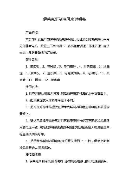
伊莱克斯制冷风扇说明书产品特点:本公司开发生产的伊莱克斯制冷风扇,行业首创冰晶制冷,采用无刷静音电机,风道上下自由调节,多档随意调速,环保节能,经济实惠,是防暑降温的好帮手。
部件名称:1、前面板,2、导风条,3、导向推杆,4、开关旋钮,5、冰晶罐,6、后面板,7、主机箱,8、电源线插头,9、电动机,10、风扇叶,11、隔板,12、接水盘使用方法:1、检查并确认机器无异常,然后放在稳定可靠的水平支撑面上。
2、把冰晶罐放入冰箱内冷冻2小时。
3、把冷冻好的冰晶罐放在伊莱克斯制冷风扇主机箱的冰晶罐安置架上。
4、确认电源插座无异常并且其供电电压与伊莱克斯制冷风扇适用的电压一致,然后把伊莱克斯制冷风扇的电源插头插入电源插座中,检查确认插接可靠。
5、把伊莱克斯制冷风扇的旋钮开关拨到“1”档,伊莱克斯制冷风扇开始以低速运转。
清洁和储藏1、伊莱克斯制冷风扇清洁前,必须切断电源,拔出电源线插头。
2、把冰晶罐从主机箱的冰晶罐安置架上取出,把冰晶罐安置架下方的隔板和接水盘取出,清空积水。
3、应用软布及非溶剂型清洁剂除去各零部件表面污垢。
4、切勿用汽油、香蕉水等溶剂擦洗,否则可能使伊莱克斯制冷风扇变色、变形、开裂。
5、切勿把伊莱克斯制冷风扇置于水中清洗。
注意事项1、为确保安全、请于使用前仔细阅读使用说明书。
2、开启产品包装后,请当即检查有无异常。
3、请勿把包装材料留给儿童或老弱病残孕者。
4、在插入电源前,请检查确认使用的电源符合伊莱克斯制冷风扇规格对应技术参数的要求。
5、本伊莱克斯制冷风扇只适合室内使用,并且应避免在浴室内使用。
16英寸Storm-Air 风扇 产品说明书

16” STORM - AIR MOVEROWNER’S MANUALOPERATING INSTRUCTIONS - MAINTENANCE - SAFETY -TROUBLESHOOTINGSerial No. Purchase Date DealerPearson Industries • 5420 Newport Drive STE 56 • Rolling Meadows, IL 60008 • Phone: (847) 963-9633Fax: (847) 963-9733 • Toll Free 888-364-9836Read and save these instructions for future reference.INTRODUCTIONCongratulations on your purchase of a new 16” Storm-Air Mover vane axial fan from Pearson In-dustries. It is our goal to provide you with the highest quality air mover. The Storm-Air Mover is durable and will provide years of trouble free service when you follow the recommendations included in this manual.Please read this manual before operating the unit. If you do not understand any portion of this manual, please contact Pearson or an autho-rized dealer for additional assistance and guid-ance before operating the fan.SAFETY INFORMATIONDO NOT operate the 16” Storm-Air Mover fan without first reading this owner’s Manual and understanding the fans operation.Pearson has endeavored to design and make the best ventilation equipment possible. How-ever, the possibility exists that the fan can be subjected to applications for which it was not designed. This misuse can lead to serious in-jury or death. Refer to current OSHA job safe-ty and health rules and regulations pertaining to the construction industry. Pay particular at-tention to the rules governing Permit-Required Confined Spaces for General Industry 29 CFR 1910.This fan is designed and made for air ventila-tion only. It is not designed to move/transport any sort of liquid or semi-liquid material.Do not operate the fan in any explosive or flammable atmosphere. Neither the mo-tor nor the fan is designed to work in such environments. Serious property damage, injury or death may result if used in an ex-plosive or flammable environment.Keep the unit grounded with a three pronged grounding plug and a grounded electrical out-let. Do not use an ungrounded extension cord or an ungrounded adapter.GETTING STARTED1) Read this owner’s manual to familiarize your-self with all warnings and precautions.2) Inspect the fan to confirm that it’s in it’s original factory configuration. If it is not, contact Pearson or an authorized Pearson representative.3) Always use your legs to lift the fan to help prevent back injury.4) The fan should not be operated by a minor. Use caution when operating this fan around chil-dren.5) Inspect the fan on a regular basis for signs of any damage and lose or worn parts. Inspect all accessories as well.6) Understand how to turn the fan off in an emer-gency. Turn it off by pushing the ON/OFF switch which is located on the side of the unit or unplug it at the power source.7) The fan uses a NEMA 5-15P plug and is de-signed to work ONLY from a grounded, 115 volt nominal AC~, 60Hz, single phase power source. This power source should utilizes a NEMA 5-15R receptacle. Use of a ground fault circuit inter-rupter (GFCI) to further protect against electrical shock hazards caused by ground faults.Always use caution before entering a con-fined space area. Test all confined space air with gas detection equipment that is appropriate for the job. Assume that a confined space is contaminated until it is proven otherwise.DANGER!DANGER!GENERAL SAFETY INFORMATION1) Do not operate any fan with a damaged cord or plug. Discard fan or return to an authorized service facility for examination and/or repair.2) Do not run cord under carpeting. Do not cover cord with throw rugs, runners, or similar cover-ings. Do not route cord under furniture or appli-ances. Arrange cord away from traffic area and where it will not be tripped over.3) Do not block the air intake grill.4) Do not put any object in the air intake grill.5) Do not place the fan in standing water be-cause of extreme shock hazard.6) Do not operate the fan outside when it is rain-ing. Only store the fan indoors.7) Do not discharge flammable solvents or chemicals through the fan air intake grill.8) Do not use the Fan in areas where flamma-ble or combustible liquids, gases, vapors, dust, fibers, or filings may be present.9) This fan is not toy.8) A properly grounded outlet should only be used with this fan.9) Unplug the fan from the power supply before servicing and when not in use.10) Do not handle the fan with wet hands. Do not pull or carry the fan by its cord, do not use cord as a handle, do not close a door on the cord, and do not pull cord around sharp edges or corners. Keep cord away from heated surfaces. Do not unplug the fan by pulling on cord, grasp the plug and not the cord.11) Do not place hair, loose clothing, fingers, and any parts of the body near the air intake grill.12) Do not allow water inside the motor. Un-plug the fan and let it dry thoroughly before using again, if the motor becomes wet.13) Do not remove ground from the power cord. Removing it may result in electrical shock or electrocution. Removing the ground will void the warranty.14) Inspect the fan if it has been dropped, left outdoors, or dropped into water, etc.. Thor-oughly inspect it prior to use.15) The Storm-Air Mover is not ductable.DO NOT USE THE FAN IF THE INLET AND OUTLET GRILLS ARE NOT INSTALLED.If the Fan is not working or if you have a question about its safe operation, do not operate it.Contact a Pearson Industries Authorized Ser-vice Center, or the factory direct at (847) 963-9633 or .DANGER!MAINTENANCEDANGER!Shut off the fan and unplug it before conduct -ing any service or inspection . Accidental elec -trocution or shock may occur if the fan is not disconnected from a power supply. Confirm that the fan blade has stopped rotating before removing the grills and handling the fan blade.1) Check for any loose or broken fasteners or components. Replace, repair or tighten as needed with only factory approved parts.2) Clean the fan blade of any debris. A build up of debris such as paint, cement dust, dirt, etc can unbalance the fan blade and damage the unit.OPERATION1) When unpacking the fan, inspect it for any damage that may have occurred during ship -ping.2) Read this manual before connecting and operating the fan.3) Determine if your job is considered hazard -ous. The working environment may contain explosive gases or dust in explosive amounts 4) The outlet to be used must be grounded.5) Make sure that both grills on the fan are not obstructed in anyway that may restrict the airflow. Do not operate the fan at anytime if the grills are not installed.6) The fan is marked with an arrow on either side. This is the direction of airflow.7) Never stand in front of the fan in the di -rection of airflow. Serious injury or death may occur from being struck with debris that are sucked into the fan and discharged at a high speed.8) Do not place the fan next to an obstructionsuch as a wall as this will decrease airflow.TROUBLESHOOTINGPROBLEM CAUSESOLUTIONUnit does not run1. Switch is not on.2. No power at outlet.3. Switch is broken.4. Loose wiring.1. Turn on switch.2. Check circuit breaker for power to outlet.3. Replace Switch.4. Check wiring, tighten as needed.Unit runs briefly, then shuts off on overload. 1. One or both grills are exhausted.2. Motor bearing are failing or have failed.3. Internal motor wiring is faulty.1. Clear grills.2. Replace motor3. Replace motor Unit vibrates exces -sively when oper -ating. 1. The fan blade is damaged.2. There is dirt build up on the fan blade.3. The motor shaft is bent because of asevere jolt.1. Replace fan blade.2. Clean fan blade.3. Replace motor. If necessary, re -place fan blade.Unit makes a scraping sound while running. 1. A severe jolt has deformed the hous -ing.2. A sever jolt has dislodged the mo -tor from the housing and/or the motormount vanes.1. Replace the housing or the entire unit if necessary.2. Replace the motor if necessary. Replace the motor mount vanes if necessary.Fan does not run, but motor makes noise. 1. A severe jolt has deformed the hous -ing causing interference with the fan blade.2. The capacitor has failed or the ca -pacitor wire is broken.1. Repair or replace the housing as necessary.2. Repair or replace the capacitor as necessary.For parts and service contact a Pearson Industries Authorized Service Center, or thefactory direct at (847) 963-9633 or .DANGER!ALL THE SERVICE PROCEDURES BELOW SHOULD BE CONDUCTED WITH THE UNITTURNED OFF AND UNPLUGGED!16” STORM-AIR MOVER EXPLODED VIEWMOTOR SPECIFICATIONSSTORM-PLUS Voltage 115V AC~Phase Single Frequency 50/60 Hz Electric Motor 1/4 hp Current (amps) 2.5R.P .M.1450Max. S.P .0.6"AIR FLOW RATES CFM M 3/Min.Free Air 226064DIMENSIONS Size 16" diameter (407 mm)Weight 34 lbs. (16 Kg)Height 22" (559 mm)Length 14" (356 mm)Width16" (407 mm)ITEM PART#DESCRIPTION 12578101111A 121414A 1718192022PII-V0139082PII-6002PII-6004PII-6010PII-00010PII-VM82510PII-V00137PII-V00011PII-S6005-USI-USI PII-V3003PII-6686K26PII-15008-NS PII-V71787PII-00163Duct Ring Screw Duct Ring/GrillFan Blade Assembly1 HP (110V 60HZ) Motor Assy. w/vanesRivetBolt (for rubber foot)Rubber FootWell Nut (for rubber foot)ShellCapacitorCable Tie (capacitor mount)Switch Plate w/gasket Switch Plate Bolt Cord Strain ReliefPII-020097A PII-08-315Rocker Switch w/cover Cord (20’ length, 110V)STORM PLUS STORMPII-S6002M PII-S16010-C16” Metal Grill1 HP (110V 60HZ) Motor Assy. w/vanes5420 Newport Drive STE 56 Rolling Meadows, IL 60008 Phone: (847) 963-9633 Fax: (847) 963-9733 Toll Free 888-364-9836© 2015 Pearson IndustriesPEARSON INDUSTRIES LIMITED WARRANTYThe original purchaser of a new Peasron Industries fan is entitled to a limited warranty subject to the terms and conditions set forth herein. Pearson’s limited warranty is for the replacement or repair of any part that proves to be defective in workmanship or materials for a period of two (2) years from the date of purchase by the original purchaser. During these two years, Pearson will provide all parts necessary to correct any defects free of charge. This limited warranty is not transferable and is only available for the original purchaser.The limited warranty is only for the repair or replacement of parts found to be defective upon Pearson’s examination. This limited warranty will be null and void unless the assembled unit is returned, freight pre-paid, together with a letter describing the problem to Pearson or an authorized Pearson dealer, This warranty is limited to ninety (90) days for labor from the date of the purchase. Thereafter, any labor costs incurred will be charged to the customer at the current hourly rate.This limited warranty is null and void if the product has been used in an improper manner, disassem -bled, altered or not maintained properly. Furthermore, this limited warranty is null and void if fan has been subjected to unauthorized repairs, corrosive chemicals, improper voltage, fire, flood, abnormal wear or any causes beyond Pearson’s control.This limited warranty is null and void if the serial number has been removed, obliterated, or defaced.Pearson Industries reserves the right to make changes to the fan design, materials or specifications as necessary and without prior notice. Pearson shall not be obliged to make any changes or modifications to any product previously manufactured.Please provide the serial number of the fan and call Pearson to receive a return authorization number. Replacements parts cannot be provided unless Pearson has the proper information from the customer.To obtain replacement parts pursuant to this limited warranty, you must write to Pearson or call (888) 364-9836 to receive an authorization number.VER. 1/2014。
电风扇操作说明书
电风扇操作说明书一、产品概述电风扇是一种常见的家用电器,用于循环空气以降低室内温度。
本操作说明书是为了帮助用户正确、安全地使用电风扇,并了解其功能和操作方法。
二、安全须知1. 在使用电风扇前,请仔细阅读并理解本操作说明书,按照指引正确操作。
2. 在插拔电源插头时,务必确保手部干燥,避免触电事故。
3. 长时间使用电风扇时,请务必注意通风情况,避免空气过于干燥或者局部氧气不足。
4. 请勿将电风扇放置在靠近水源的地方,避免发生漏电等安全隐患。
5. 操作完毕后,请将电源插头拔出插座,以免浪费用电和发生意外。
三、产品组成1. 主体部分:包括电机、叶片和外壳。
2. 控制面板:包括开关按钮、风速控制按钮和定时器按钮(视具体型号而定)。
四、使用方法1. 将电风扇放置在平稳的底座上,并确保插座与电风扇之间的电源线连接牢固。
2. 打开电源开关按钮,此时电风扇处于待机状态。
3. 按下风速控制按钮,可以切换不同的风速档位。
通常有低速、中速和高速可选择。
4. 如需设置定时器功能,按下定时器按钮,并按照显示屏上的指引设置持续时间。
在设定时间后,电风扇将自动关闭。
5. 在使用过程中,如果需要调整风向,可手动调整电风扇的头部角度,确保风吹到所需位置。
6. 使用结束后,按下电源开关按钮,关闭电风扇。
五、注意事项1. 使用过程中,请勿将手指、头发等物体靠近电风扇的叶片,以免发生伤害。
2. 对于儿童和宠物,请保持距离,避免发生触电或其他危险。
3. 长时间使用后,电风扇可能会产生一定的噪音,请尽量放置在安静的环境中使用,以免干扰休息或工作。
4. 如发现产品存在故障或异常情况,请立即停止使用,并咨询专业技术人员进行检修或维护。
六、清洁与维护1. 在清洁电风扇前,请先将插头拔出插座,并等待其完全停止运转。
2. 使用干布或柔软的刷子轻轻擦拭电风扇的表面,避免使用水或化学溶液直接清洁。
3. 定期清洁电风扇的叶片和滤网,以免积尘影响使用效果。
4. 如发现电风扇存在异常噪音、震动等情况,请及时联系售后服务中心或专业技术人员进行检修。
乐简台式风扇的说明书
乐简台式风扇的说明书性能要求1.电源电压:160VAC~250VAC,50Hz2.工作环境温度:20℃~+70 3.工作环境湿度:10%~一90%一、运行模式1.自动2.节能3.睡眠4.送风二、控制目标1.电机:高、中、低、节能档、自动档2.导风轮((同步电机>3、七段数码管码(显示档位)4、LED灯5、蜂鸣器三、输入参数1.室内环境温度(以下简称RT)2.预设时间(以下简称BT)设定温度简称为ST3.用户按键信息四、按键说明1.“开/关”键:用于控制器运行的开启与关闭。
上电后首次开机时(延时2秒钟动作)。
蜂鸣器响一长声,进入送风。
1.“开/关”键:用于控制器运行的开启与关闭。
上电后首次开机时(延时2秒钟动作)。
蜂鸣器响一长声,进入送风。
2.“模式”键:按键可按下述操作:(模式切换时延时2秒动作)应当三种模式切换还包括普通运行→自动→睡眠3.“风速”键:按键可按下述操作:(风速切换时延时2秒动作)自然→>低一>中→>高-4.“▲”键:通常按“”键可设置设定关机时间五、模式说明1.自动模式RT>25℃时:选择高风,ST为21℃。
21℃≤RT≤25℃时:选择中风,ST为22℃。
RT<21℃时选择低风,ST 为23℃。
自动模式下设定温度不可调,系统自动根据室温选择运行模式和设定温度。
2.睡眠模式电机中风10秒停3秒3.自然模式电机高风8秒后低风3秒六、其它控制1.风摆的控制:控制导风轮转动(视情况而定)2.蜂鸣器的控制:开机时:长鸣2s模式撤换:1短声档位撤换:1短声七、保护措施:1.倒下自动断电保护:当检测到风扇倒下时,风扇自动关机。
2.待机保护:风扇开启12小时内无键盘操作,风扇自动关机。
3.制热过热保护:电机温度超过49℃时,风扇自动关机。
风扇说明书
风扇说明书风扇说明书1. 产品概述风扇是一种常见的家用电器,用于产生空气流动,提供凉爽的环境。
本风扇说明书将为您提供关于风扇的详细信息,包括产品特点、使用方法和注意事项等。
2. 产品特点- 高效节能:本风扇采用先进的节能技术,可提供强劲的风力同时降低能耗。
- 多功能控制:具备多种控制方式,如遥控器、触摸面板和机械开关,方便用户选择。
- 静音运行:采用静音设计,确保风扇运行时产生的噪音最低限度。
- 可调节角度:风扇头部可上下调节,可根据需要调整风向和风力。
- 环保材料:选择高质量的环保材料制造,无害人体健康。
3. 使用方法3.1 组装在使用风扇之前,您需要进行简单的组装。
1. 取出风扇包装盒,检查产品是否完好。
2. 打开风扇包装箱,取出风扇主体和底座部分。
3. 将底座部分插入风扇主体底部的插槽中,确保底座稳固。
4. 根据需要,连接风扇电源线。
3.2 启动和操作风扇提供多种操作方式。
- 使用遥控器:按下遥控器上的开关按键,风扇将启动。
您可以使用遥控器调节风速、风向和定时功能等。
- 使用触摸面板:触摸面板位于风扇主体上,可实现与遥控器相同的功能。
- 使用机械开关:在风扇主体上方或底座上,有一个机械开关,将其拨到合适的档位即可启动风扇。
3.3 清洁和维护为确保风扇的正常运转和延长使用寿命,建议您定期清洁和维护风扇。
1. 关闭风扇电源,拔掉电源插头。
2. 使用柔软的布料蘸取温水或中性清洁剂,擦拭风扇表面。
避免使用酸性或腐蚀性清洁剂,以免损坏产品。
3. 清洁风扇叶片时,可以使用软毛刷小心地除去灰尘。
4. 在清洁过程中,避免弄湿风扇内部,以免引起电气故障。
5. 清洁完成后,确保风扇完全干燥后再通电使用。
4. 注意事项- 在使用风扇之前,请仔细阅读本说明书,并按照说明正确操作以确保安全。
- 使用风扇时,请确保插头和插座干燥,插头与插座连接牢固。
- 长时间使用风扇时,建议定期休息一段时间,以避免疲劳。
- 风扇必须放置在平稳的表面上,以防止倾倒和损坏。
电风扇说明书格式范文

电风扇说明书格式范文嗨,朋友!欢迎你拥有这台超棒的电风扇。
在你开始享受清凉之前,先来看看这个简单的说明书吧。
一、外观部件。
1. 扇叶。
这可是风扇的核心部件之一哦。
扇叶就像小翅膀一样,高速旋转起来就能把风呼呼地吹出来。
可别随便去掰它,要是变形了,风扇就不能好好工作啦,而且还可能会有危险呢。
2. 网罩。
前面的网罩是为了保护你不被快速转动的扇叶碰到。
它就像一个小卫士,紧紧地守护着扇叶。
后面也有个网罩,这两个网罩把扇叶夹在中间,让风扇安全又可靠。
3. 电机外壳。
电机就在这个外壳里面,它可是风扇的动力源泉。
电机要是累了,风扇可就转不动了,所以要好好对待它。
这个外壳摸起来可能有点凉凉的,那是正常的哦。
4. 支柱。
支柱就像风扇的大长腿,把扇头和底座连接起来。
有些支柱可以调节高度,这样你就可以根据自己的需求,把风扇调得高高的或者矮矮的。
5. 底座。
底座是风扇的根基,它要稳稳地站在地上或者桌子上。
有些底座里面还可以放一些小物件呢,是不是很贴心?二、功能介绍。
1. 风速调节。
我们的风扇一般有好几个风速档哦。
就像跑步有慢跑、快跑一样,风扇也有微风、中风和强风档。
如果你刚从外面回来,热得不行,那就直接开到强风档,让大风呼呼地吹走你的燥热。
要是你只是想有点微微的凉风,微风档就很合适啦。
你只要找到风扇上的风速调节按钮,按一按就能轻松切换风速啦。
2. 摇头功能。
这个功能可厉害了。
按下摇头按钮,风扇的脑袋就会左右摆动,这样就能把风送到更大的范围。
就像一个小舞者在左右摇摆,把清凉带给更多的地方。
如果不想让它摇头了,再按一下这个按钮就好啦。
3. 定时功能。
有时候我们可能想让风扇吹一会儿就自动停下来,这时候定时功能就派上用场了。
你可以根据自己的需要,设置15分钟、30分钟、1个小时等等不同的时间。
设置好之后,风扇就会乖乖地按照你设定的时间工作,然后自动休息啦。
就像一个听话的小助手。
三、使用注意事项。
1. 放置位置。
要把风扇放在平稳的地方,无论是地面还是桌面,都要保证它不会轻易晃动或者倾倒。
智能风扇Nimbus产品说明书

The driving fo r ce SmartFan®NimbusFEATURES•Controls fan/motor speed based on:— 4-20 mA control signal— 2-10 VDC control signal— Remote temperature sensors (supplied separately)— Remote transducer (humidity, pressure, flow etc.)— On board pressure transducer•Power source: 95-250 VAC, automatically detected •Frequency: 47-64 Hz, automatically detected•Fan On/Off threshold selectable by DIP Switch•AC Motor Type Compatibility: PSC (Permanent Split Capacitor) or Shaded Pole, automatically detected.•Full voltage start pulse•RoHS (6/6) compliant•UL recognized to UL508, CSA-C22.2,File E100344SELECTABLE OPTIONS•Current ratings: 2.5A to 7.5A (at 40C still air)•Mounting Options: PCB mount, DIN Rail mount, 4x4electrical job box mount•4 selectable temperature settings•10 selectable pressure settings•64 selectable fixed speed settings •Temperature alarm and lost signal alarm •Accepts up to 3 temperature sensors•Selectable idle speeds and control temperature slopeSmartFan Nimbus is a compact, TRIAC based fan & motor control designed for OEM applications in HVAC, electronic and industrial control markets. The Nimbus automatically controls single phase motors that have been approved for voltage control by the motor manufacturer. Typical applications include: humidity control, clean room pressurization, equipment cooling, ceiling fans, exhaust ventilators, pumps, duct fans & blowers. The Nimbus regulates motor speed from a control signal (2-10 VDC, 4-20 mA), humidity sensor, pressure transducer, flow transducer or up to 3 remote temperature sensors. Automatic voltage and frequency detection, current ratings up to 7.5A and 3 mounting and connection configurations, including DIN rail mount and ”4x4 job box” mount, make this microprocessor based design extremely flexible and economical.Speed Control for AC Fans, Pumps and MotorsCONTROLP/N 240B7T00-Fwith DIN350-F DIN rail mount kit (sold separately).P/N 240BJW00-Fwith 4x4 Job Box (not supplied) in background.P/N 240B2T00-FACControlsSmartFan ®NimbusCONTROL Nimbus Control Mode2Current Rating /Packaging4ConnectorSpecial FeaturesRoHS Compliant240B = Current, Voltage, Temp., Remote Transducer or Fixed Speed T = Temperature & Transducer only 32 = .15 - 2.5A3 = .15 - 3.0A (Job Box only)6 = .50 - 6.0A 7 = .50 - 7.5AJ = .50 - 7.0A (Job Box only)T = Terminal Block W = 18 AWG Wires(Job Box only)00 = Standard -F = 6/6 RoHS Compliant DIN350-F Din Rail Kit1Confirm TRIAC (voltage) controllability with the fan/motormanufacturer before ordering.2When used in the temperature or remote transducer control mode (T), a sensor (sold separately) is required. Choose a compatible SmartFan Sensor shown in the CRI catalog or website at or control via your own transducer.3A minimum order of 50 units is required to supply T models.440°C, still air, max current rating. Maximum surge current not to exceed 24 AmpsPART NUMBERING SYSTEM 1X = 0.86(21.8) at 2.5 A X = 1.06(26.9) at 6 A X = 2.06(52.3) at 7.5 AElectrical job box mount styleP/N 240XJWxxCONTROL RESOURCES INCORPORATEDTEL: (978) 486-4160 FAX: (978) 486-4772Email:********************Page 3 of 8CONFIRM FAN/MOTOR COMPATIBILITYConfirm TRIAC (voltage control) compatibility with the fan/motor manufacturer before installation.Attempting to control a motor that is not compatible could cause excessive heating and permanent damage.SETTING CONTROL MODES (switches #7,8)Unless otherwise specified, the Nimbus is factory set to control fans in the Temperature Control mode. Tocontrol via a current or voltage source, remote powered transducer or fixed speed setting, set switches 7 and 8 as shown below, then refer to the control mode section you have selected to customize the Nimbus for your application. For on board pressure control models,(2401xx00 and 2405xx00) refer to “USING PRESSURE CONTROL MODELS” section.USING CURRENT OR VOLTAGE CONTROL MODEUnless otherwise specified, the Nimbus is factory set to control fans in the “Temperature Control” mode. To switch to controlling fan speed via a “Control Signal”, refer to table 2. Select the type of control signal you are using [I for 0-20mA (30mA Max.) or V for 0-10VDC (12VDC max.)] using the jumper on header J1. The Nimbus can also be customized to accept other control schemes, contact customer service for details.Setting Idle Speed (switch #2,3): The idle speed is the minimum voltage (as a % of supply voltage) supplied to the fan. The Nimbus is factory set for idle speeds of 30, 40, 50 and 60% by setting DIP switches 2 and 3. The default idle setting is 50%. Other idle speeds can besupplied, contact customer service for details.Fan On / Fan Off Feature (switch #1): To turn fan(s) off below the set idle speed (see table 3), set switch #1 to the ON position. To keep fans running at idle speed below the set idle speed, set switch #1 to the OFF position.Control Signal Loss Options (switch #6): If the control signal is lost, (less than 4mA in I mode, less than 2VDC in V mode) when switch 6 is OFF fans will continue to idle or remain off. To send fans to full speed if thecontrol signal is lost (less than 4mA in I mode, less than 2VDC in V mode) set switch 6 to the ON position.60%20% 40%100% 80%410820mA 4VDC 2VACFigure 6USING TEMPERATURE CONTROL MODEThe Nimbus can automatically control temperature (air, liquid or surface) by proportionately increasing ordecreasing fan speed as required. Up to 3 sensors can be used to sense temperature. When more than one sensor is used, the hottest sensor will control fan speed. To set the Nimbus to temperature control mode refer to table 2.Control Temperature (switch #4,5): The controltemperature is the point above which fans will run at full speed (T C ). The Nimbus is factory set to control fans at 30, 35, 40 or 45˚C by setting DIP switches 4 and 5. The default setting is 35˚C. Other temperature setting can be supplied, contact customer service for details.CONTROLSetting Idle Speed (switch #2,3): The idle speed is the minimum voltage (as a % of supply voltage) supplied to the fan. The Nimbus is factory set for idle speeds of 30, 40, 50 and 60% by setting DIP switches 2 and 3, see table #3. The default setting is at 50%. Other idle speeds can be supplied, contact customer service for details. See figure 7.Temperature Slope (switch #6): The temperature slope (T S ) is the temperature difference between idle speed and full speed. The slope can be set at 4˚C or 10˚C by using DIP switch #6. The default setting is 4˚C. Other slopes can be supplied, contact customer service for details. See figure 7.Fan On / Fan Off Feature (switch #1): To turn fans off automatically when temperatures drop below the set idle temperature (T C – T S ), set switch #1 to the ON position. To keep fans running at idle speed below the set idle temperature, set switch #1 to the OFF position. See figure 7.C S60% 20%40%100% 80% CT VACFigure 7USING REMOTE POWERED TRANSDUCER MODEWhen used in the remote transducer mode, the Nimbus can power and control from most 0-5VDC transducers (humidity, pressure, flow etc.) with a maximum supply current of 5mA. To set the Nimbus to remote transducer mode, see table 2.Setting Control Parameters (switch #3,4,5,6): To customize the control slope to your transducer, use DIP switches 3 & 4 to set idle or minimum speed voltage, use switches 5 & 6 to set full speed control voltage. See table 6, and figure 8 for details.VDC(min)60%20%40% 100% 80%VDC(max)VACFigure 8Fan On / Fan Off Feature (switch #1): To turn fans off automatically when transducer voltage drops below VDC (min), set switch #1 to the ON position. To keep fans running at idle speed below the VDC(min), set switch #1 to the OFF position. See figure 8.Setting Idle Speed (switch #2): The idle speed is the minimum voltage (as a % of supply voltage) supplied to the fan. When used in the remote transducer mode, the Nimbus can be set for idle speeds of 30% by setting DIP switch #2 to OFF or 60% by setting DIP switch #2 to ON. Other idle speeds can be supplied, contact customer service for details. See figure 8.USING FIXED SPEED MODEAutomatic speed control can be overridden in the fixed speed mode. To set the Nimbus to fixed speed mode, see table 2. In the fixed speed mode, the user can select motor voltages from 27% to 99% (in 1% or 2% increments) of supply voltage using DIP switches 1 through 6, see table 7.versions of the Nimbus can be used with MeasurementSpecialties () humidity sensor P/NHM1500LF or an on-board pressure sensor factory setto 0.10” to 1.00” or 0.50 to 5.00 H2O. Contact customerservice for details.MOUNTINGElectrical “job box” mount (Fig 3): The Nimbus can besupplied in circuit board form or with a cover, ready tomount in a standard 4x4x1.5 electrical job box. Whensupplied in the job box form, part number 240_JW__ or240_3W__, connections are made through 4.0” (10cm),18AWG wires. Wires should be terminated using wirenuts (not included) according to local electrical codes.Unused wires may be cut off at the circuit board or canbe depopulated at the factory for production orders.Caution: bundling unused wires together may cause ashort and damage the unit.Circuit Board Form: When supplied in the circuit boardform, a spacing of ¼” (6.3mm) should be maintainedbetween the circuit board and chassis ground and 5/16”(8mm) to any uninsulated secondary circuits to satisfysafety agency requirements. To enable part numbers240x6xxx or 240x7xxx to pass HI-POT testing, avoidmaking connection to ground at the mounting holeclosest to the heatsink, H1. See Figure 4.DIN Rail Option (Fig 1): Units supplied in circuit boardform may be mounted on a DIN rail using DIN rail kit CRI#DIN350-F.CONTROLCONNECTIONSWARNING: Dangerous voltages are present on the circuit board when connected to the power line. Power must be removed before making any connections or adjustments to avoid electrical shock or damage to the unit.Power Connections: It is recommended that an adequately sized circuit breaker be connected between the power service and the control to permit fail-safe removal of power before making adjustments or connections. Connect line power (white) to location N. Connect line power (black) to location L. When using an electrical “job box” mount version secure any ground (green) wire to a steel electrical box or consult local electrical codes.The Nimbus is not compatible with Uninterruptible Power Supplies (UPS) that generate a square wave.Fan Connections: Connect fan or fans to positions marked F (red) and L (black). Any number of fans may be controlled in parallel from one unit as long as the total current does not exceed the current rating. See table 1 and figure 9.Temperature Sensor Selection and Connection: The Nimbus will accept signals from up to 3 temperature sensors and control fan speed based on the hottest sensor. Choose an air, surface or liquid temperature sensor from the CRI catalog or website at Each sensor, S1, S2, S3 shares a common return marked SRTN. CAUTION: SRTN is a non-isolated input; use CRI sensor P11-F or other sensor with a jacketed cable if installing temperature sensors in a dwelling. When fewer than 3 sensors are used, sensors may be hooked up to S1, S2 or S3. In “Temperature mode”, if no sensors are connected or all sensors read below -25°C, fans will run at full speed and the temperature alarm will activate. The Nimbus can also be supplied with a board mount sensor, contact customer service for details. See wiring diagram, figure 9.Remote Powered Transducer Connections: When used in the remote transducer mode, the Nimbus can power and control from any 0-5VDC transducer (humidity, pressure, flow etc.) with a maximum supply current of 5mA. Connect the + lead to SRTN, connect – to S1, connect Vout to S2.Refer to “USING REMOTE POWERED TRANSDUCER MODE” section to set control parameters for your transducer. Over Temperature and Loss of Signal Alarm Connection (for 240Bxxxx models only): When used in the temperature control mode, (see table 2) an over-temperature alarm can be triggered when thetemperature goes 10˚C (18˚F) above the control temperature (T C) or below -25°C. When used in the Voltage or Current signal mode a “loss of signal” alarm can be triggered when DIP switch #6 is in the ON position. Alarm connections are made at –ALM+The alarm output is a normally open, optically isolated MOS Relay. When no alarm condition is present, the relay is closed and can conduct up to 100 ma. AC or DC, of load current. When the alarm is triggered, the relay opens, and can support up to 300 Volts AC or DC across its terminals. Other alarm trigger points can be supplied, contact customer service for details. See figure 9, 9a,9b or 9c for possible alarm configurations.Current or Voltage Control Signal Connections: When used in the current or voltage control mode (see table 2), connect a 0-10VDC or 0-20mA control signal to –ISO+ as shown in figure 9.CONTROLInput ConfigurationsCONTROLCONTROL TEL: (978) 486-4160TESTING & TECHNICAL DATAFan Compatibility : The Nimbus is compatible withmany PSC (Permanent Split Capacitor) and shaded pole motors. The Nimbus is not compatible with capacitor start motors. Confirm TRIAC controllability with the motor manufacturer before installation. Attempting to control a fan that is not compatible could causeexcessive heating and could permanently damage the fan motor.Control Accuracy and Hysteresis : The standard Nimbus is accurate to within ±1.5˚C in the temperature control mode and ±0.4VDC, ±0.8mA in the control signal mode. If your application requires greater accuracy, contact customer service. For most single-phase AC fans, there is direct correlation between fan speed and voltage. For some fans however, this will not be the case. To prevent fans (using fan ON/OFF feature) and alarms from cycling on and off, a certain amount ofhysteresis has been built in to the Nimbus. That is, fans will shut off 2-3% below the set point and turn back on 2-3% above the set point. Alarms will turn on at the setpoint and turn off 1-2°C below or 5% above the set point.Voltage Loss: For a typical fan, expect a voltage drop to the fan of about 2-4% at full voltage.Changing Control Settings : With the exception of the “fixed speed mode”, the Nimbus will not recognize any changes in switch or jumper settings made with power applied. Power must be turned OFF before changing any switch or jumper settings.Minimum fan currents : Fans may not control properly if the total fan current is less than the minimum published current, see table 1.Maximum fan currents : Some motors draw higher current at less than maximum voltage. Contact motor manufacturer for details.Start Pulse : Some fans that run just fine at lower voltages will not start at these voltages; therefore the Nimbus will start fans at full voltage for 2 seconds before throttling back to the appropriate control speed.EMI: The amount of electrical noise emitted by theNimbus increases as fan speed decreases. The amount of noise emitted is fan dependant. If the electrical noise is an issue, an AC Input Line Filter can be used. CRI recommends the following line filters from or equivalent.Current Derating : The Nimbus may be run above 40˚C. However, the maximum current ratings will decline according the chart below.601060%20%40% CURRENT DERATING VS AMBIENT TEMP.100% 80%8070% Rated Current20304050Ambient Temperature C°Figure 10Specifications:• Power Source: 95 – 250 VAC• Frequency: 47-64 Hz • Current Ratings: see table 1• Storage Temperature: -40˚C to 125˚C • Operating Temperature: -25˚C to 70˚CControl Resources has been a leading provider of off-the-shelf and custom fan controls and alarms since 1984. Control Resources can offer DC Speed Controls, AC Speed Controls, Tach Alarms, Fan Trays, Lab Test Equipment and complete custom design and manufacturing services. With in house ISO 9001 design andmanufacturing capabilities, CRI is the One-Stop-Shop for all your thermal design needs. For information on other CRI products, see our website at or contact Control Resources, Inc.。
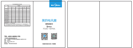
美的FS40-16FRA电风扇使用说明书
WIFI风扇应用系统框架图
使用注意事项
- 为了避免金属屏蔽效应影响通信,WIFI风扇与金属/家电需保持50cm以上距离;- 支持设备:
iOS 6.0及以上操作系统的移动终端;
Android 2.3.6及以上操作系统的移动终端;
- 在2G/3G/4G网络下使用美的APP软件进行远程操作,会产生通信流量;
- 如需获得更多信息和服务,请拨打美的服务热线:400-8899-315。
打开阿里智能APP,点击登录。
输入账号和密码进行登录(如没账号需
先进行注册)。
等待配网完成。
添加成功后,会进入该家电的控制页面
(控制页面也可以从首页点击该家电进入)。
3、家电配网流程
登录成功后,点击添加设备。
点击“按分类查找”->“风扇”->“美的
风扇FS40-16FRA”,如图示按提示操作
家电,将风扇上电后,在开机状态下,同时
按下“风类”和“摇头”键,听到滴一声,
家电进入配网模式,APP上点击“下一步”。
输入要连接到的WiFi密码,点击“搜索设备”。
4、风扇与阿里智能APP连接后,使用APP控制开关、风类、风速及设置定时预约
在APP首页,点击要控制的家电。
在控制界面可对开关机、风类和风速进行
控制。
在开机状态下可设置预约,在关机状态下
可设置定时。
APP定时时间小于30分钟
以下的数码屏显示0.5小时,大于等于30
分钟以上的显示1小时,10小时以上时间
位显示1小时方式。
6
87。
智能风扇控制器的说明书

智能风扇控制器的说明书
感谢您购买本产品,本说明书将详细介绍智能风扇控制器的使用、功能及相关注意事项。
在使用本产品之前,请务必认真阅读本说明书并按照说明操作。
一、产品介绍
智能风扇控制器是一款可控制风扇转速的智能设备。
该设备集成了先进的智能控制芯片,可以通过上下左右方向键调节风扇转速,同时还可以设置定时开关机,方便实用。
本设备支持多个风扇同时使用,有效的解决了多风扇管理问题。
二、使用说明
(一)设置风扇转速
1.将电源插座插入智能风扇控制器。
2.将风扇插入智能风扇控制器后面的风扇接口。
3.按下设备上的上下左右方向键,可分别调节风扇的转速。
(二)设置定时开关机
1.按下设备上的“定时”键,设备进入定时模式。
2.按下“加”或“减”键,可分别设置开启或关闭设备的时间。
3.完成设定后,再次按下“定时”键,退出定时模式。
三、注意事项
1.请勿将本产品安装在阳台等露天场所,以免受到雨水等天气影响。
2.请勿将本产品长时间处在高温潮湿的环境中,否则可能导致设备
内部电路损坏。
3.本设备采用220V电源,请勿插入与其电压不符的电源。
4.请勿将本设备接入过载的电路中,以免引起电路过负载而导致电
器故障或火灾等危险事故。
感谢您阅读本说明书,如有任何问题或者建议,欢迎随时与我们联系。
我们会尽最大的努力为您解决问题并提供优质的服务。
- 1、下载文档前请自行甄别文档内容的完整性,平台不提供额外的编辑、内容补充、找答案等附加服务。
- 2、"仅部分预览"的文档,不可在线预览部分如存在完整性等问题,可反馈申请退款(可完整预览的文档不适用该条件!)。
- 3、如文档侵犯您的权益,请联系客服反馈,我们会尽快为您处理(人工客服工作时间:9:00-18:30)。
23/22 2700/3000 2.60/3.20
12038L
B S
220/240 0.09/0.08 50/60
16/15 2250/2450 2.12/2.31
东莞市冠凌实业有限公司 地址:东莞市寮步镇凫山乐平19号 电话:0769-33381187 33390027 传真:0769-82319770 联系人:燕小姐 手机:13728128080 邮编:523401 网址:
0.12/0.11
50/60
12/11 2500/2850
0.07/0.06
50/60
14/13 2500/2850
风量 (Air Flow)
(CFM)
0.50/0.60
0.50/0.60
东莞市冠凌实业有限公司 地址:东莞市寮步镇凫山乐平19号 电话:0769-33381187 33390027 传真:0769-82319770 联系人:燕小姐 手机:13728128080 邮编:523401 网址:
邮编:523401
网址:
GL18060交流散热风机产品说明
外框尺寸: 180X180X60mm
TOPCOOL
设计特点: 铝合金外框,含玻纤PBT扇叶 lmpedance protected
轴承: 滚珠轴承
ed 工作环境温度: r 滚珠轴承-30℃ to +75℃
转速
风量
(Speed) (Air Flow)
(RPM)
(CFM)
2450/2850 0.80/1.01
220/240 0.08/0.06
50/60
14/13 2500/2950 0.85/1.05
S
东莞市冠凌实业有限公司 地址:东莞市寮步镇凫山乐平19号 电话:0769-33381187 33390027 传真:0769-82319770 联系人:燕小姐 手机:13728128080 邮编:523401 网址:
10.8
20060H
B
220
0.45
50
65
2650
10.8
东莞市冠凌实业有限公司 地址:东莞市寮步镇凫山乐平19号 电话:0769-33381187 33390027 传真:0769-82319770 联系人:燕小姐 手机:13728128080 邮编:523401 网址:
is 参数表:
g 型号 e (Model) UnR 15050H
轴承 (Bearing)
B:Ball S:Sleeve
B S B S B
电压 (Voltage)
(VAC)
110/120
220/240
电流 (Current)
(AMP)
0.51/0.48
0.23/0.21
频率 (Frequency)
(Hz)
GL12038交流散热风机产品说明
外框尺寸: 120X120X38mm
TOPCOOL
设计特点: 铝合金外框,含玻纤PBT扇叶 lmpedance protected
轴承: 含油或滚珠轴承
工作环境温度:
d 含油轴承-10℃ to +70℃
滚珠轴承-30℃ to +75℃
re 重量: te 530g
is 参数表:
功率 (Power) (WATTS)
16/15
16/15
转速 (Speed)
(RPM)
2250/2350
2250/2350
风量 (Air Flow)
(CFM)
1.86/2.20
1.86/2.20
东莞市冠凌实业有限公司 地址:东莞市寮步镇凫山乐平19号 电话:0769-33381187 33390027 传真:0769-82319770 联系人:燕小姐 手机:13728128080 邮编:523401 网址:
(WATTS) (RPM) (m3/min)
50
2700
8.5
18060H
B
220
0.35
50
50
2700
8.5
东莞市冠凌实业有限公司 地址:东莞市寮步镇凫山乐平19号 电话:0769-33381187 33390027 传真:0769-82319770 联系人:燕小姐 手机:13728128080 邮编:523401 网址:
g 轴承 e 型号 (Bearing)
(Model) B:Ball S:Sleeve
R B n S
12025H B
U S
电压 (Voltage)
(VAC)
110/120
220/240
电流 (Current)
(AMP)
0.18/0.17
0.09/0.08
频率 (Frequency)
(Hz)
50/60
50/60
GL22060交流散热风机产品说明
外框尺寸: 220X60mm
TOPCOOL
设计特点: 铝合金外框,含玻纤PBT扇叶 lmpedance protected
轴承: 滚珠轴承
ed 工作环境温度: r 滚珠轴承-30℃ to +75℃
te 重量: is 1700g
g 参数表:
Re 型号(Model) Un 22060H
g 型号 e (Model) UnR 12038H
轴承
电压
(Bearing) (Voltage)
B:Ball S:Sleeve
(VAC)
B S
110/120
B S
220/240
B S
380
电流 (Current)
(AMP)
0.22/0.20
0.11/0.10
0.06
频率 (Frequency
(Hz)
功率
转速
(Power) (Speed)
(WATTS) (RPM)
14/13 2200/2400
14/13 2200/2850
风量 (Air Flow)
(CFM)
0.60/0.71
0.68/0.88
东莞市冠凌实业有限公司 地址:东莞市寮步镇凫山乐平19号 电话:0769-33381187 33390027 传真:0769-82319770 联系人:燕小姐 手机:13728128080 邮编:523401 网址:
50/60
50/60
50
功率 (Power) (WATTS)
21/19
21/19
19
转速 (Speed)
(RPM)
2650/2950
2650/2950
2600
风量 (Air Flow)
(m3/min)
2.50/3.10
2.50/3.10
2.49
12038X
B S
220/240 0.14/0.12 50/60
is 轴承
型号 (Bearing)
(Model) B:Ball
g S:Sleeve e B
S
R 8038H B Un S
电压 (Voltage)
(VAC)
110/120
220/240
电流 (Current)
(AMP)
0.14/0.13
0.08/0.07
频率 (Frequency)
(Hz)
50/60
50/60
GL12025交流散热风机产品说明
外框尺寸: 120X120X25mm
TOPCOOL
设计特点: 铝合金外框,含玻纤PBT扇叶 lmpedance protected
轴承: 含油或滚珠轴承
工作环境温度:
d 含油轴承-10℃ to +70℃
滚珠轴承-30℃ to +75℃
re 重量: te 330g
is 参数表:
50/60
50/60
功率 (Power) (WATTS)
36/34
36/34
转速 (Speed)
(RPM)
2650/3050
2650/3050
风量 (Air Flow)
(m3/min)
5.30/6.50
5.30/6.50
380
0.11
50
34
2700
5.30
S
东莞市冠凌实业有限公司 地址:东莞市寮步镇凫山乐平19号 电话:0769-33381187 33390027 传真:0769-82319770 联系人:燕小姐 手机:13728128080
转速(Speed)
(Hz)
(WATTS)
(RPM)
50/60
16/15 2250/2350
50/60
16/15 2250/2350
S
风量 (Air Flow)
(CFM)
1.70/2.00
1.70/2.00
东莞市冠凌实业有限公司 地址:东莞市寮步镇凫山乐平19号 电话:0769-33381187 33390027 传真:0769-82319770 联系人:燕小姐 手机:13728128080 邮编:523401 网址:
g 轴承
型号 (Bearing)
e (Model) B:Ball
S:Sleeve
电压 (Voltage)
(VAC)
电流 (Current)
(AMP)
频率 (Frequency)
(Hz)
R B
110/120 0.13/0.11
50/60
n S
9225H
U B
功率 (Power) (WATTS)
13/12
(Bearing) 型号(Model)
g B:Ball
S:Sleeve
e B R S
8025H
n B U S