DRA240-48B中文资料
D、DG、、DF、DY、MD系列多级离心泵(D240-46D240-40)
概述D型泵是采用JB/T6435.2及GB5659-85《多级离心泵技术条件》、MT/T114-2005《煤矿用多级离心泵》制造的卧式分段式多级离心泵,它适合于输送清水(杂质含量小于1%,固体颗粒小于0.1毫米)及物理化学性质类似于清水的其它液体。
也可通过改变材质、密封型式和增加冷却系统而适用于输送热水、油品、腐蚀性介质等。
D型泵输送的介质温度不大于800C,适用于高层建筑或大型建筑的生活(增压)供水、排水和消防以及空调机组的冷却水循环等。
DG(锅炉给水泵):输送的介质温度不大于105℃,适合于输送热水的场合。
如锅炉给水、城市和企业的供暖系统。
根据输送的介质不同D型泵可分为:DY(多级离心油泵):输送不含固体颗粒、温度为-20~1050C、粘度小于120厘泊的油类和石油产品。
DF(耐腐蚀多级离心泵):输送不含固体颗粒、温度为-20~1050C的腐蚀性液体。
MD(耐磨矿用多级离心泵):输送颗粒含量≤1.5%,粘度≤0.5mm温度为-20~1050C的中性矿井水及其他类似的污水.参数范围:额定流量:6—740米3/小时额定杨程:40-690米(扬程的高低可通过增减泵的级数来达到)转速:2900转/分,1450转/分型号意义D(DG、DF、DY、MD) 4 6 — 5 0 × 1 0100 D(DG、DF、DY、MD)16 × 3泵的级数泵的级数泵的单级扬程(m)泵的单级扬程(m)泵的流量(m3/h)卧式多级泵卧式多级泵泵进口直径(m m)泵的轴承规格结构说明泵的结构参见结构图本系列多级泵为两端支承,泵通过弹性柱销联轴器与电机联接。
泵的旋转方向从驱动端看为顺时针旋转。
D型泵吸入口呈水平方向,出水口为垂直向上。
DG型泵的进出水口均为垂直向上。
多级泵存在着较大的轴向力(与泵的级数成正比),轴向力全部由平衡机构平衡,轴承不承受轴向力。
泵在运行时允许转子有轴向串动,故不能采用向心轴承。
轴承采用钙基黄油润滑。
DXI800 中文手册

2005 Beckman Coulter, Inc. P/N 986266E 3/05
i
UniCel DxI 800 使用说明
目录
4 样品架和样品容器 . . . . . . . . . . . . . . . . . . . . . . . . . . . . . . . . . . . . . . . . . . .4-1
本手册与 UniCel DxI Access 免疫分析系统 一同使用。
Access、 AccuTnI、 DxI、 Hybritech、 Ostase、 UniCel 以及 BECKMAN COULTER 徽标是 Beckman Coulter, Inc. 的商标
UniCel DxI 800 使用说明
2 关闭和重新启动 . . . . . . . . . . . . . . . . . . . . . . . . . . . . . . . . . . . . . . . . . . . . .2-1
SP240A资料
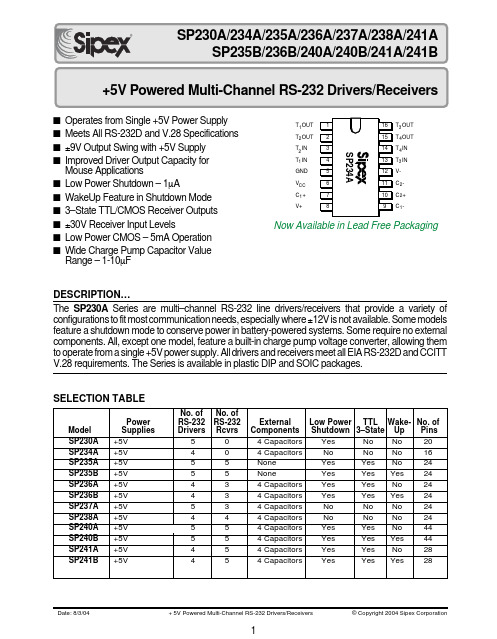
■Operates from Single +5V Power Supply ■Meets All RS-232D and V.28 Specifications ■±9V Output Swing with +5V Supply ■Improved Driver Output Capacity for Mouse Applications■Low Power Shutdown – 1µA■WakeUp Feature in Shutdown Mode ■3–State TTL/CMOS Receiver Outputs ■±30V Receiver Input Levels■Low Power CMOS – 5mA Operation ■Wide Charge Pump Capacitor Value Range – 1-10µFDESCRIPTION…The SP230A Series are multi–channel RS-232 line drivers/receivers that provide a variety of configurations to fit most communication needs, especially where ±12V is not available. Some models feature a shutdown mode to conserve power in battery-powered systems. Some require no external components. All, except one model, feature a built-in charge pump voltage converter, allowing them to operate from a single +5V power supply. All drivers and receivers meet all EIA RS-232D and CCITT V.28 requirements. The Series is available in plastic DIP and SOIC packages.SELECTION TABLET OUT T OUT T IN T IN V- C - C + C -34221T OUT T OUT T IN T IN GND V C + V+12CC 12134Now Available in Lead Free Packaging元器件交易网ABSOLUTE MAXIMUM RATINGS This is a stress rating only and functional operation of the device at these or any other conditions above those indicated in the operation sections of this specification is not implied. Exposure to absolute maximum rating conditions for extended periods of time may affect reliability.VCC ...............................................................................................................................................................+6VV+...................................................................................................................(Vcc–0.3V) to +13.2V V–.............................................................................................................................................................13.2V Input Voltages:T IN .......................................................................................................................–0.3 to (Vcc +0.3V)RIN ............................................................................................................................................................±30VOutput Voltages:TOUT.................................................................................................(V+, +0.3V) to (V–, –0.3V)ROUT..............................................................................................................–0.3V to (Vcc +0.3V)Short Circuit Duration:TOUT.........................................................................................................................................ContinuousPower Dissipation:CERDIP..............................................................................675mW(derate 9.5mW/°C above +70°C)Plastic DIP..........................................................................375mW(derate 7mW/°C above +70°C)Small Outline......................................................................375mW(derate 7mW/°C above +70°C)ELECTRICAL CHARACTERISTICS元器件交易网0V 5V 0V5V 0V0VT INT INT OUTT OUTR L = 3k Ω, C L = 2,500pFNo loadTransmitter Propagation DelayTransmitter Output WaveformsReceiver Output WaveformShutdown to V+, V– Rise TimeInOut5V 0V 0VSDV +V –Rise TimeR L = 3k Ω; C L = 2,500pF All inputs = 20kHzT INT OUTT INT OUTFall TimeR L = 3k Ω; C L = 2,500pFReceiver Propagation DelayRIN 5V 0VR OUT5V 0VR IN5V 0VR OUTPINOUTFall Time Rise TimeReceiver Output Enable/Disable TimesDisable5V 0V5V 0VEN INR OUTEnable5V 0V5V 0VEN INR OUTPINOUTFEATURES…The multi–channel RS-232 line drivers/receivers pro-vides a variety of configurations to fit most communi-cation needs, especially those applications where ±12V is not available. The SP230A, SP235A/B, SP236A/B, SP240A/B, and SP241A/B feature ashutdown mode which reduces device power dissipa-tion to less than 5µW. All feature low power CMOS operation, which is particularly beneficial in battery-powered systems. The SP235A/B use no external components and are ideally suited where printed circuit board space is limited.All products in the Series include two charge pump voltage converters which allow them to operate from a single +5V supply. These converters convert the +5V input power to the ±10V needed to generate the RS-232 output levels. An internal charge pump converter produces the necessary –12V supply. All drivers and receivers meet all EIA RS-232D and CCITT V.28 specifications.The Series are available for use over the commer-cial, industrial and military temperature ranges. They are packaged in plastic DIP and SOIC packages. For product processed and screened to MIL–M–38510 and MIL–STD–883C require-ments, please consult the factory.THEORY OF OPERATIONThe SP230A/B–241A/B series devices are made up of t hree b asic c ircuit b locks –1) t ransmitter, 2) r eceiver and 3) charge pump. Each model within the series incorporates variations of these circuits to achieve the desired configuration and performance.Driver/TransmitterThe drivers are inverting transmitters, which accept TTL or CMOS inputs and output the RS-232 signals with an inverted sense relative to the input logic levels. Typically the RS-232 output voltage swing is ±9V. Even under worst-case loading conditions of 3kΩand 2500pF, the output is guaranteed to be ±5V, which is consistent with the RS-232 standard specifications. The transmitter outputs are protected against infi-nite short-circuits to ground without degradation in reliability.The drivers of the SP230A, SP235A/B, SP236A/B, SP240A/B and SP241A/B can be tri-stated by using the SHUTDOWN function. In this “power-off” state, the output impedance will remain greater than 300 Ohms, again satisfying the RS-232 specifications. Should the input of the driver be left open, an internal 400kΩ pull–up resistor to VCCforces the input high, thus committing the output to a low state.The slew rate of the transmitter output is internally limited to a maximum of 30V/µs in order to meet theTable 1. EIA Standards Definition 元器件交易网Charge Pump Output Loading versus VCC; a) V+; b) V–ENABLE Input (EN)The SP235A/B , SP236A/B , SP240A/B, and SP241A/B all feature an enable input (EN),which allows the receiver outputs to be either tri–stated or enabled. The enable input is active outputs. This can be especially useful when the receiver is tied directly to a microprocessor data bus.Protection From Shorts to >±15VThe driver outputs are protected against shorts to ground, other driver outputs, and V + or V -.For protection against voltages exceeding ±15V,two back–to–back zener diodes connected to clamp the outputs to an acceptable voltage level are recommended. (Refer to Figure 3.)Improved Drive Capability for Mouse ApplicationsEach of the devices in this data sheet have improved drive capability for non-standard ap-plications. Although the EIA RS-232D stan-dards specify the maximum loading to be 3k Ωand 2500pF, the SP230A , SP234A , SP235A/B ,SP236A/B , SP237A , SP238A , SP240A/B, and SP241A/B can typically drive loads as low as 1k Ω and still maintain ±5V outputs. This feature is especially useful when the serial port is in-tended to be used for a “self-powered” mouse.In this case the voltage necessary to operate the circuits in the mouse can be derived from the RS-232 driver output as long as the loading is ≥1k Ω (refer to Figure 4). For applications which even exceed this requirement, drivers can be connected in parallel, increasing the drive capa-bility to 750Ω, while maintaining the ±5V V OH and V OL levels (refer to Figure 5).Figure 3. High Voltage Short Circuit ProtectionFigure 2. Charge Pump Voltage Inverter output impedance of V + and V -, which will degrade V OH and V OL . Capacitor values can be as low as 1.0µF.Shutdown (SD)The SP230A , SP235A/B , SP236A/B , SP240A/B and SP241A/B all feature a control input which will disable the part and reduce V CC current typically to less than 5µA, which is especially useful to designers of battery–pow-ered systems. In the “power–off” mode the receiver and transmitter will both be tri-stated.V + will discharge to V CC , and V - will discharge to ground.For complete shutdown to occur and the 10µA current drain to be realized, the following con-ditions must be met:• +5.00V must be applied to the SD pin;• ENABLE must either 0V, +5.0V or not connected;• the transmitter inputs must be either +5.0V or not connected;• V CC must be +5V;• Receiver inputs must be >0V and <+5VPlease note that for proper operation, the SD input pin must never be left floating.Table 2. Wake–Up Truth TableFigure 4. Mouse Application Drive Capability 10 9 8 7 6 5 4 3 2 1 0V O L /V O H (V o l t s )246810121820I OL /I OH (mA)161422V OL vs I OLV OH vs I OHFigure 5. Parallel DriversWake-Up FeatureThe SP235B , SP236B , SP240B and SP241B have a wake-up feature that keeps all receivers in an enabled state when the device is in the shutdown mode. Table 2 defines the truth table for the wake-up function. Timing for the wake-up function is shown in Figure 6.If the SP235B , SP236B , SP240B and SP241B are powered up in the shutdown state (SD driven high during V CC power up), the part must remain in a powered on state for a minimum of 3ms before the wake-up function can be used. After the 3ms wait time, there is a 2ms delay time before data is valid for both enable and disableFigure 6. Wake–Up and Shutdown Timing元器件交易网of the charge pump. If the SP2XXB is powered up with SD low, then only the 2ms delay time will apply (refer to Figure 6). Under normal operation, both the wait time and delay time should be transparent to the user.With only the receivers activated, the device typically draws less than 5µA (10µA max) sup-ply current. In the case of a modem interfaced to a computer in power-down mode, the RI (ring indicator) signal from the modem would be used to “wake up” the computer, allowing it to accept the data transmission.After the ring indicator signal has propagated through the SP2XXB receiver, it can be used to trigger the power management circuitry of the computer to power up the microprocessor and bring the SD pin to the SP2XXB low, taking it out of shutdown. The receiver propagation de-lay is typically 1µs. The enable time for V+ and V- is typically 2ms. After V+ and V- have settled to their final values, a signal can be sent back to the modem on the DTR (Data Terminal Ready) pin signifying that the computer is ready to accept and transmit data.All receivers that are active during shutdown maintain 500mV (typ.) of hysteresis.Varying Capacitor ValuesAs stated earlier, the capacitor values are some-what non-critical. Since they are an actual compo-nent of the charge pump circuitry, their value will affect its performance, which in turn affects the V OH and V OL levels. There is no upper limit for the value of any of the four capacitors; lower values will impact performance. C 1 and C 2 are respon-sible for the charge accumulation and can be reduced to 1µF; this will increase the output im-pedance of V + and V –. Reducing these capacitor values will limit the ability of the SP2XXA/B to maintain the dc voltages needed to generate the RS-232 output levels. Capacitors C 3 and C 4 can also be reduced to 1µF; doing so will increase the ripple on V + and V–.Typically each driver will require 1µF of capaci-tance as a minimum to operate within all specified parameters; if five drivers are active in the circuit,then C 3 and C 4 should be 5µF. In order to operateat these minimum values, the supply voltage must be maintained at +5.0V ±5%. Also, the ambient operating temperature must be less than 60°C.The capacitor values must be chosen to suit the particular application. The designer must bal-ance board space, cost and performance to maxi-mize the design. The capacitors can be polarized or non–polarized, axial-leaded or surface-mount.As the size and value decrease, so does the cost;however, the value should be chosen to accom-modate worst-case load conditions.IBM Modem Port InterconnectionsINTERFACE EXAMPLE – A MODEM ON THE IBM PC SERIAL PORTThe RS-232 standard defines 22 serial interface signals. These signals consist of ground lines,timing, data, control and test signals, plus a set of signals rarely used for a second data channel.Many of these signal lines are not used in typical RS-232 applications; in fact, the IBM ® PC serial port is implemented using only nine pins.For example, consider the case of a PC using this nine pin port to communicate with a peripheral device such as a modem. We see the following activity on each of the RS-232 lines as the computer and modem are activated and commu-nicate with each other as well as the remote modem at the other end of the phone line.Signal Ground (GND)The Signal Ground pin acts as a reference for all the other signals. This pin is simply maintained at a 0V level to serve as a level to which all other signals are referenced. Both the PC and the modem will have this line connected to their respective internal ground lines.元器件交易网Data Terminal Ready (DTR)This is the pin the computer uses to tell periph-eral devices that it is on–line and ready to communicate.Data Set Ready (DSR)Peripheral devices use this line to tell the com-puter that they are on–line and ready to commu-nicate. When the modem is turned on and has completed its self–test routine (assuming it does one), it will send a signal to the PC by asserting this line.Request To Send (RTS)The computer activates this line to notify the peripheral device that it is ready to send data. In this example, the computer notifies the modem that it is ready to send data to be transmitted by the modem.Clear To Send (CTS)This is the line on which the peripheral device tells the computer that it is ready to receive data from the computer. If the modem was not ready, i.e. it was performing a loop–back self–test, for example, it would not assert this line. Once the modem was ready to receive data from the PC, it would assert this line. When it receives the CTS signal from the modem, the PC knows that a data transmission path has been established between itself and the modem.Transmitted Data (TD or TX)This is the pin on which the computer sends the actual data signal to be transmitted, i.e. a posi-tive voltage (+3V to +15V) to represent a logic “0”, and a negative voltage (–3V to –15V) to represent a logic “1”. The PC would send the data on this line to be transmitted by the modem. Ring Indicator (RI)This line is used by the peripheral device to tell the computer that a remote device wants to start communicating. The modem would activate the RI line to tell the computer that the remote modem was calling, i.e. the phone is ringing. Data Carrier Detect (DCD)This line is used by the modem to tell the computer that it has completed a transmission path with the remote modem, and to expect to start receiving data at any time.Received Data (RD or RX)This is the pin on which the modem sends the computer the incoming data signal, i.e. a posi-tive voltage (+3V to +15V) to represent a logic “0”, and a negative voltage (-3V to -15V) to represent a logic “1”.INTERFACE EXAMPLE – A PRINTER ON THE IBM PC SERIAL PORTThe RS-232 standard defines 22 serial interface signals. These signals consist of ground lines, timing, data, control and test signals, plus a set of signals rarely used for a second data channel. Many of these signal lines are not used in typical RS-232 applications; in fact, the IBM® PC serial port is implemented using only nine pins.For example, consider the case of a PC using this nine pin port to communicate with a peripheral device such as a printer. We see the following activity on each of the RS-232 lines as the com-puter and printer are activated and communicate. Signal Ground (GND)The Signal Ground pin acts as a reference for all the other signals. This pin is simply maintained at a 0V level to serve as a level to which all other signals are referenced. Both the PC and the printer will have this line connected to their respective internal ground lines.Data Terminal Ready (DTR)This is the pin the computer uses to tell peripheral devices that it is on–line and ready to communi-IBM Printer Port Interconnections元器件交易网cate. Once the computer is powered–up and ready, it will send out a signal on the DTR to inform the printer that it is powered–up and ready to go. The printer really doesn’t care, since it will simply print data as it is received. Accordingly, this pin is not needed at the printer.Data Set Ready (DSR)Peripheral devices use this line to tell the computer that they are on–line and ready to communicate. When the printer is turned on and has completed its self–test routine (assuming it does one), it will send a signal to the PC by asserting this line. Request To Send (RTS)The computer activates this line to notify the peripheral device that it is ready to send data. In this example, the computer notifies the printer that it is ready to send data to be printed by the printer. Clear To Send (CTS)This is the line on which the peripheral device tells the computer that it is ready to receive data from the computer. If the printer was not ready, i.e. it was out of paper, for example, it would not assert this line. Once the printer was ready to receive data from the PC, it would assert this line. When it receives the CTS signal from the printer, the PC knows that a data transmission path has been established between itself and the printer. Transmitted Data (TD or TX)This is the pin on which the computer sends the actual data signal representing the actual informa-tion to be printed, i.e. a positive voltage (+3V to +15V) to represent a logic “0”, and a negative voltage (-3V to -15V) to represent a logic “1”. Ring Indicator (RI)This line is used by the peripheral device to tell the computer that a remote device wants to start com-municating. A modem would activate the RI line to tell the computer that a remote modem was calling, i.e. the phone is ringing. In the case of a printer, this line is unused.Data Carrier Detect (DCD)This line is used by a peripheral device to tell the computer to expect to start receiving data at any time. Since the printer would not be sending data to the PC in this case this line is not needed.Received Data (RD or RX)This is the pin on which the computer receives the incoming data signal, i.e. a positive voltage (+3V to +15V) to represent a logic “0”, and a negative voltage (-3V to -15V) to represent a logic “1”. Again, in this instance, since the printer will not be sending the PC any data, this line is not needed.元器件交易网ORDERING INFORMATIONModel .......................................................................................Temperature Range....................................................................PackageSP230ACP .....................................................................................0°C to +70°C ...............................................................................20 pin PDIP SP230ACT .....................................................................................0°C to +70°C ............................................................................20 pin WSOIC SP230ACT/TR ...............................................................................0°C to +70°C ............................................................................20 pin WSOIC SP230ACX .....................................................................................0°C to +70°C ............................................................................................Dice SP230AEP ...................................................................................–40°C to +85°C .............................................................................20 pin PDIP SP230AET ...................................................................................–40°C to +85°C ..........................................................................20 pin WSOIC SP230AET/TR .............................................................................–40°C to +85°C ..........................................................................20 pin WSOIC SP234ACP .....................................................................................0°C to +70°C ...............................................................................16 pin PDIP SP234ACT .....................................................................................0°C to +70°C ............................................................................16 pin WSOIC SP234ACT/TR ...............................................................................0°C to +70°C ............................................................................16 pin WSOIC SP234ACX .....................................................................................0°C to +70°C ............................................................................................Dice SP234AEP ...................................................................................–40°C to +85°C .............................................................................16 pin PDIP SP234AET ...................................................................................–40°C to +85°C ..........................................................................16 pin WSOIC SP234AET/TR .............................................................................–40°C to +85°C ..........................................................................16 pin WSOIC SP235ACP .....................................................................................0°C to +70°C ...............................................................................24 pin PDIP SP235AEP ...................................................................................–40°C to +85°C .............................................................................24 pin PDIP SP235BCP .....................................................................................0°C to +70°C ...............................................................................24 pin PDIP SP235BEP ...................................................................................–40°C to +85°C .............................................................................24 pin PDIP SP236ACS .....................................................................................0°C to +70°C ...............................................................................24 pin PDIP SP236ACT .....................................................................................0°C to +70°C ............................................................................24 pin WSOIC SP236ACT/TR ...............................................................................0°C to +70°C ............................................................................24 pin WSOIC SP236ACX .....................................................................................0°C to +70°C ............................................................................................Dice SP236AES ...................................................................................–40°C to +85°C .............................................................................24 pin PDIP SP236AET ...................................................................................–40°C to +85°C ..........................................................................24 pin WSOIC SP236AET/TR .............................................................................–40°C to +85°C ..........................................................................24 pin WSOIC SP236BCS .....................................................................................0°C to +70°C .............................................................................. 24 pin PDIP SP236BCT .....................................................................................0°C to +70°C ............................................................................24 pin WSOIC SP236BCT /TR ..............................................................................0°C to +70°C ............................................................................24 pin WSOIC SP236BCX .....................................................................................0°C to +70°C ............................................................................................Dice SP236BES ...................................................................................–40°C to +85°C .............................................................................24 pin PDIP SP236BET ...................................................................................–40°C to +85°C ..........................................................................24 pin WSOIC SP236BET /TR ............................................................................–40°C to +85°C ..........................................................................24 pin WSOIC SP237ACS .....................................................................................0°C to +70°C ...............................................................................24 pin PDIP SP237ACT .....................................................................................0°C to +70°C ............................................................................24 pin WSOIC SP237ACT/TR ...............................................................................0°C to +70°C ............................................................................24 pin WSOIC SP237ACX .....................................................................................0°C to +70°C ............................................................................................Dice SP237AES ...................................................................................–40°C to +85°C .............................................................................24 pin PDIP SP237AET ...................................................................................–40°C to +85°C ..........................................................................24 pin WSOIC SP237AET/TR .............................................................................–40°C to +85°C ..........................................................................24 pin WSOIC/TR = Tape and ReelPack quantity is 1,500 for WSOIC.Available in lead free packaging. To order add "-L" suffix to part number.Example: SP230AEP = standard; SP230AEP-L = lead free Please consult factory for SP235B, SP236B, SP240B, SP241B, and dice.CorporationANALOG EXCELLENCESipex Corporation Headquarters and Sales Office233 South Hillview Drive Milpitas, CA 95035TEL: (408) 934-7500FAX: (408) 935-7600元器件交易网。
LSE240D8;中文规格书,Datasheet资料
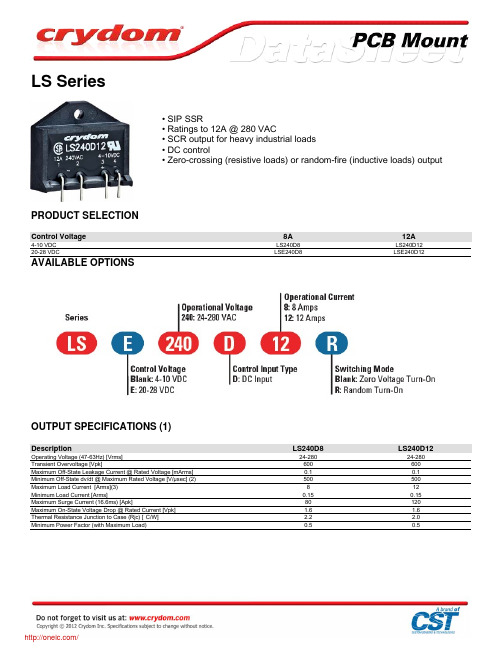
WIRING DIAGRAM
/
MECHANICAL SPECIFICATIONS
THERMAL DERATE INFORMATION
AGENCY APPROVALS
E116950
LR816889 (For 12A models only)
R72060707
Rev. 111611
LS
4-10 VDC 4.0 VDC 1.0 VDC 15 mAdc 270 Ohm 1/2 Cycle 1/2 Cycle
LSE
20-28 VDC 20 VDC 1.0 VDC 15 mAdc 1500 Ohm 1/2 Cycle 1/2 Cycle
GENERAL SPECIFICATIONS
Description
PRODUCT SELECTION
Control Voltage
4-10 VDC 20-28 VDC
8A
LS240D8 LSE240D8
12A
LS240D12 LSE240D12
AVAILABLE OPTIONS
OUTPUT SPECIFICATIONS (1)
Description
Operating Voltage (47-63Hz) [Vrms] Transient Overvoltage [Vpk] Maximum Off-State Leakage Current @ Rated Voltage [mArms] Minimum Off-State dv/dt @ Maximum Rated Voltage [V/µsec] (2) Maximum Load Current [Arms](3) Minimum Load Current [Arms] Maximum Surge Current (16.6ms) [Apk] Maximum On-State Voltage Drop @ Rated Current [Vpk] Thermal Resistance Junction to Case (Rjc) [°C/W] Minimum Power Factor (with Maximum Load)
MAX485CPA+中文资料
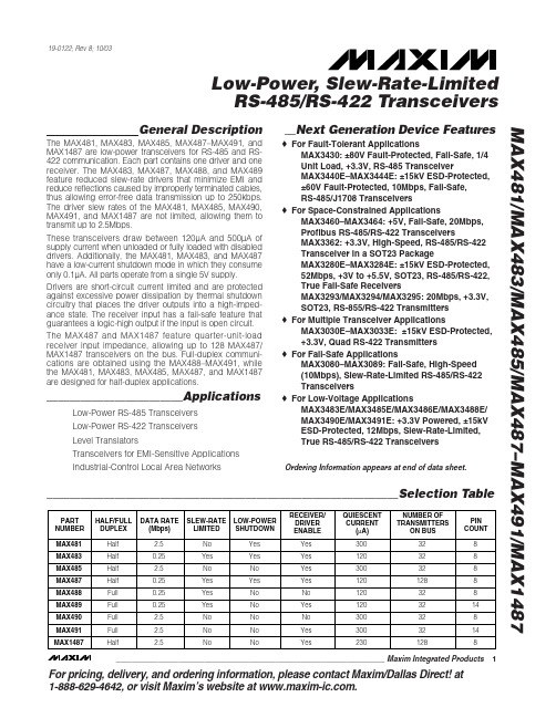
For pricing, delivery, and ordering information,please contact Maxim/Dallas Direct!at 1-888-629-4642, or visit Maxim’s website at .General DescriptionThe MAX481, MAX483, MAX485, MAX487–MAX491, and MAX1487 are low-power transceivers for RS-485 and RS-422 communication. Each part contains one driver and one receiver. The MAX483, MAX487, MAX488, and MAX489feature reduced slew-rate drivers that minimize EMI and reduce reflections caused by improperly terminated cables,thus allowing error-free data transmission up to 250kbps.The driver slew rates of the MAX481, MAX485, MAX490,MAX491, and MAX1487 are not limited, allowing them to transmit up to 2.5Mbps.These transceivers draw between 120µA and 500µA of supply current when unloaded or fully loaded with disabled drivers. Additionally, the MAX481, MAX483, and MAX487have a low-current shutdown mode in which they consume only 0.1µA. All parts operate from a single 5V supply.Drivers are short-circuit current limited and are protected against excessive power dissipation by thermal shutdown circuitry that places the driver outputs into a high-imped-ance state. The receiver input has a fail-safe feature that guarantees a logic-high output if the input is open circuit.The MAX487 and MAX1487 feature quarter-unit-load receiver input impedance, allowing up to 128 MAX487/MAX1487 transceivers on the bus. Full-duplex communi-cations are obtained using the MAX488–MAX491, while the MAX481, MAX483, MAX485, MAX487, and MAX1487are designed for half-duplex applications.________________________ApplicationsLow-Power RS-485 Transceivers Low-Power RS-422 Transceivers Level TranslatorsTransceivers for EMI-Sensitive Applications Industrial-Control Local Area Networks__Next Generation Device Features♦For Fault-Tolerant ApplicationsMAX3430: ±80V Fault-Protected, Fail-Safe, 1/4Unit Load, +3.3V, RS-485 TransceiverMAX3440E–MAX3444E: ±15kV ESD-Protected,±60V Fault-Protected, 10Mbps, Fail-Safe, RS-485/J1708 Transceivers♦For Space-Constrained ApplicationsMAX3460–MAX3464: +5V, Fail-Safe, 20Mbps,Profibus RS-485/RS-422 TransceiversMAX3362: +3.3V, High-Speed, RS-485/RS-422Transceiver in a SOT23 PackageMAX3280E–MAX3284E: ±15kV ESD-Protected,52Mbps, +3V to +5.5V, SOT23, RS-485/RS-422,True Fail-Safe ReceiversMAX3293/MAX3294/MAX3295: 20Mbps, +3.3V,SOT23, RS-855/RS-422 Transmitters ♦For Multiple Transceiver ApplicationsMAX3030E–MAX3033E: ±15kV ESD-Protected,+3.3V, Quad RS-422 Transmitters ♦For Fail-Safe ApplicationsMAX3080–MAX3089: Fail-Safe, High-Speed (10Mbps), Slew-Rate-Limited RS-485/RS-422Transceivers♦For Low-Voltage ApplicationsMAX3483E/MAX3485E/MAX3486E/MAX3488E/MAX3490E/MAX3491E: +3.3V Powered, ±15kV ESD-Protected, 12Mbps, Slew-Rate-Limited,True RS-485/RS-422 TransceiversMAX481/MAX483/MAX485/MAX487–MAX491/MAX1487Low-Power, Slew-Rate-Limited RS-485/RS-422 Transceivers______________________________________________________________Selection Table19-0122; Rev 8; 10/03Ordering Information appears at end of data sheet.M A X 481/M A X 483/M A X 485/M A X 487–M A X 491/M A X 1487Low-Power, Slew-Rate-Limited RS-485/RS-422 Transceivers 2_______________________________________________________________________________________ABSOLUTE MAXIMUM RATINGSSupply Voltage (V CC ).............................................................12V Control Input Voltage (RE , DE)...................-0.5V to (V CC + 0.5V)Driver Input Voltage (DI).............................-0.5V to (V CC + 0.5V)Driver Output Voltage (A, B)...................................-8V to +12.5V Receiver Input Voltage (A, B).................................-8V to +12.5V Receiver Output Voltage (RO).....................-0.5V to (V CC +0.5V)Continuous Power Dissipation (T A = +70°C)8-Pin Plastic DIP (derate 9.09mW/°C above +70°C)....727mW 14-Pin Plastic DIP (derate 10.00mW/°C above +70°C)..800mW 8-Pin SO (derate 5.88mW/°C above +70°C).................471mW14-Pin SO (derate 8.33mW/°C above +70°C)...............667mW 8-Pin µMAX (derate 4.1mW/°C above +70°C)..............830mW 8-Pin CERDIP (derate 8.00mW/°C above +70°C).........640mW 14-Pin CERDIP (derate 9.09mW/°C above +70°C).......727mW Operating Temperature RangesMAX4_ _C_ _/MAX1487C_ A...............................0°C to +70°C MAX4__E_ _/MAX1487E_ A.............................-40°C to +85°C MAX4__MJ_/MAX1487MJA...........................-55°C to +125°C Storage Temperature Range.............................-65°C to +160°C Lead Temperature (soldering, 10sec).............................+300°CDC ELECTRICAL CHARACTERISTICS(V CC = 5V ±5%, T A = T MIN to T MAX , unless otherwise noted.) (Notes 1, 2)Stresses beyond those listed under “Absolute Maximum Ratings” may cause permanent damage to the device. These are stress ratings only, and functional operation of the device at these or any other conditions beyond those indicated in the operational sections of the specifications is not implied. Exposure to absolute maximum rating conditions for extended periods may affect device reliability.V V IN = -7VV IN = 12V V IN = -7V V IN = 12V Input Current (A, B)I IN2V TH k Ω48-7V ≤V CM ≤12V, MAX487/MAX1487R INReceiver Input Resistance -7V ≤V CM ≤12V, all devices except MAX487/MAX1487R = 27Ω(RS-485), Figure 40.4V ≤V O ≤2.4VR = 50Ω(RS-422)I O = 4mA, V ID = -200mV I O = -4mA, V ID = 200mV V CM = 0V-7V ≤V CM ≤12V DE, DI, RE DE, DI, RE MAX487/MAX1487,DE = 0V, V CC = 0V or 5.25VDE, DI, RE R = 27Ωor 50Ω, Figure 4R = 27Ωor 50Ω, Figure 4R = 27Ωor 50Ω, Figure 4DE = 0V;V CC = 0V or 5.25V,all devices except MAX487/MAX1487CONDITIONSk Ω12µA ±1I OZRThree-State (high impedance)Output Current at ReceiverV 0.4V OL Receiver Output Low Voltage 3.5V OH Receiver Output High Voltage mV 70∆V TH Receiver Input Hysteresis V -0.20.2Receiver Differential Threshold Voltage-0.2mA 0.25mA-0.81.01.55V OD2Differential Driver Output (with load)V 2V 5V OD1Differential Driver Output (no load)µA±2I IN1Input CurrentV 0.8V IL Input Low Voltage V 2.0V IH Input High Voltage V 0.2∆V OD Change in Magnitude of Driver Common-Mode Output Voltage for Complementary Output States V 0.2∆V OD Change in Magnitude of Driver Differential Output Voltage for Complementary Output States V 3V OC Driver Common-Mode Output VoltageUNITS MINTYPMAX SYMBOL PARAMETERMAX481/MAX483/MAX485/MAX487–MAX491/MAX1487Low-Power, Slew-Rate-Limited RS-485/RS-422 Transceivers_______________________________________________________________________________________3SWITCHING CHARACTERISTICS—MAX481/MAX485, MAX490/MAX491, MAX1487(V CC = 5V ±5%, T A = T MIN to T MAX , unless otherwise noted.) (Notes 1, 2)DC ELECTRICAL CHARACTERISTICS (continued)(V CC = 5V ±5%, T A = T MIN to T MAX , unless otherwise noted.) (Notes 1, 2)ns 103060t PHLDriver Rise or Fall Time Figures 6 and 8, R DIFF = 54Ω, C L1= C L2= 100pF ns MAX490M, MAX491M MAX490C/E, MAX491C/E2090150MAX481, MAX485, MAX1487MAX490M, MAX491MMAX490C/E, MAX491C/E MAX481, MAX485, MAX1487Figures 6 and 8, R DIFF = 54Ω,C L1= C L2= 100pF MAX481 (Note 5)Figures 5 and 11, C RL = 15pF, S2 closedFigures 5 and 11, C RL = 15pF, S1 closed Figures 5 and 11, C RL = 15pF, S2 closed Figures 5 and 11, C RL = 15pF, S1 closed Figures 6 and 10, R DIFF = 54Ω,C L1= C L2= 100pFFigures 6 and 8,R DIFF = 54Ω,C L1= C L2= 100pF Figures 6 and 10,R DIFF = 54Ω,C L1= C L2= 100pF CONDITIONS ns 510t SKEW ns50200600t SHDNTime to ShutdownMbps 2.5f MAX Maximum Data Rate ns 2050t HZ Receiver Disable Time from High ns 103060t PLH 2050t LZ Receiver Disable Time from Low ns 2050t ZH Driver Input to Output Receiver Enable to Output High ns 2050t ZL Receiver Enable to Output Low 2090200ns ns 134070t HZ t SKD Driver Disable Time from High |t PLH - t PHL |DifferentialReceiver Skewns 4070t LZ Driver Disable Time from Low ns 4070t ZL Driver Enable to Output Low 31540ns51525ns 31540t R , t F 2090200Driver Output Skew to Output t PLH , t PHL Receiver Input to Output4070t ZH Driver Enable to Output High UNITS MIN TYP MAX SYMBOL PARAMETERFigures 7 and 9, C L = 100pF, S2 closed Figures 7 and 9, C L = 100pF, S1 closed Figures 7 and 9, C L = 15pF, S1 closed Figures 7 and 9, C L = 15pF, S2 closedM A X 481/M A X 483/M A X 485/M A X 487–M A X 491/M A X 1487Low-Power, Slew-Rate-Limited RS-485/RS-422 Transceivers 4_______________________________________________________________________________________SWITCHING CHARACTERISTICS—MAX483, MAX487/MAX488/MAX489(V CC = 5V ±5%, T A = T MIN to T MAX , unless otherwise noted.) (Notes 1, 2)SWITCHING CHARACTERISTICS—MAX481/MAX485, MAX490/MAX491, MAX1487 (continued)(V CC = 5V ±5%, T A = T MIN to T MAX , unless otherwise noted.) (Notes 1, 2)3001000Figures 7 and 9, C L = 100pF, S2 closed Figures 7 and 9, C L = 100pF, S1 closed Figures 5 and 11, C L = 15pF, S2 closed,A - B = 2VCONDITIONSns 40100t ZH(SHDN)Driver Enable from Shutdown toOutput High (MAX481)nsFigures 5 and 11, C L = 15pF, S1 closed,B - A = 2Vt ZL(SHDN)Receiver Enable from Shutdownto Output Low (MAX481)ns 40100t ZL(SHDN)Driver Enable from Shutdown toOutput Low (MAX481)ns 3001000t ZH(SHDN)Receiver Enable from Shutdownto Output High (MAX481)UNITS MINTYP MAX SYMBOLPARAMETERt PLH t SKEW Figures 6 and 8, R DIFF = 54Ω,C L1= C L2= 100pFt PHL Figures 6 and 8, R DIFF = 54Ω,C L1= C L2= 100pFDriver Input to Output Driver Output Skew to Output ns 100800ns ns 2000MAX483/MAX487, Figures 7 and 9,C L = 100pF, S2 closedt ZH(SHDN)Driver Enable from Shutdown to Output High2502000ns2500MAX483/MAX487, Figures 5 and 11,C L = 15pF, S1 closedt ZL(SHDN)Receiver Enable from Shutdown to Output Lowns 2500MAX483/MAX487, Figures 5 and 11,C L = 15pF, S2 closedt ZH(SHDN)Receiver Enable from Shutdown to Output Highns 2000MAX483/MAX487, Figures 7 and 9,C L = 100pF, S1 closedt ZL(SHDN)Driver Enable from Shutdown to Output Lowns 50200600MAX483/MAX487 (Note 5) t SHDN Time to Shutdownt PHL t PLH , t PHL < 50% of data period Figures 5 and 11, C RL = 15pF, S2 closed Figures 5 and 11, C RL = 15pF, S1 closed Figures 5 and 11, C RL = 15pF, S2 closed Figures 5 and 11, C RL = 15pF, S1 closed Figures 7 and 9, C L = 15pF, S2 closed Figures 6 and 10, R DIFF = 54Ω,C L1= C L2= 100pFFigures 7 and 9, C L = 15pF, S1 closed Figures 7 and 9, C L = 100pF, S1 closed Figures 7 and 9, C L = 100pF, S2 closed CONDITIONSkbps 250f MAX 2508002000Maximum Data Rate ns 2050t HZ Receiver Disable Time from High ns 25080020002050t LZ Receiver Disable Time from Low ns 2050t ZH Receiver Enable to Output High ns 2050t ZL Receiver Enable to Output Low ns ns 1003003000t HZ t SKD Driver Disable Time from High I t PLH - t PHL I DifferentialReceiver SkewFigures 6 and 10, R DIFF = 54Ω,C L1= C L2= 100pFns 3003000t LZ Driver Disable Time from Low ns 2502000t ZL Driver Enable to Output Low ns Figures 6 and 8, R DIFF = 54Ω,C L1= C L2= 100pFns 2502000t R , t F 2502000Driver Rise or Fall Time ns t PLH Receiver Input to Output2502000t ZH Driver Enable to Output High UNITS MIN TYP MAX SYMBOL PARAMETERMAX481/MAX483/MAX485/MAX487–MAX491/MAX1487Low-Power, Slew-Rate-Limited RS-485/RS-422 Transceivers_______________________________________________________________________________________530002.5OUTPUT CURRENT vs.RECEIVER OUTPUT LOW VOLTAGE525M A X 481-01OUTPUT LOW VOLTAGE (V)O U T P U T C U R R E N T (m A )1.515100.51.02.0203540450.90.1-50-252575RECEIVER OUTPUT LOW VOLTAGE vs.TEMPERATURE0.30.7TEMPERATURE (°C)O U T P U TL O W V O L T A G E (V )500.50.80.20.60.40100125-20-41.5 2.0 3.0 5.0OUTPUT CURRENT vs.RECEIVER OUTPUT HIGH VOLTAGE-8-16M A X 481-02OUTPUT HIGH VOLTAGE (V)O U T P U T C U R R E N T (m A )2.5 4.0-12-18-6-14-10-203.54.5 4.83.2-50-252575RECEIVER OUTPUT HIGH VOLTAGE vs.TEMPERATURE3.64.4TEMPERATURE (°C)O U T P UT H I G H V O L T A G E (V )0504.04.63.44.23.83.01001259000 1.0 3.0 4.5DRIVER OUTPUT CURRENT vs.DIFFERENTIAL OUTPUT VOLTAGE1070M A X 481-05DIFFERENTIAL OUTPUT VOLTAGE (V)O U T P U T C U R R E N T (m A )2.0 4.05030806040200.5 1.5 2.53.5 2.31.5-50-2525125DRIVER DIFFERENTIAL OUTPUT VOLTAGEvs. TEMPERATURE1.72.1TEMPERATURE (°C)D I F FE R E N T I A L O U T P U T V O L T A G E (V )751.92.21.62.01.8100502.4__________________________________________Typical Operating Characteristics(V CC = 5V, T A = +25°C, unless otherwise noted.)NOTES FOR ELECTRICAL/SWITCHING CHARACTERISTICSNote 1:All currents into device pins are positive; all currents out of device pins are negative. All voltages are referenced to deviceground unless otherwise specified.Note 2:All typical specifications are given for V CC = 5V and T A = +25°C.Note 3:Supply current specification is valid for loaded transmitters when DE = 0V.Note 4:Applies to peak current. See Typical Operating Characteristics.Note 5:The MAX481/MAX483/MAX487 are put into shutdown by bringing RE high and DE low. If the inputs are in this state for lessthan 50ns, the parts are guaranteed not to enter shutdown. If the inputs are in this state for at least 600ns, the parts are guaranteed to have entered shutdown. See Low-Power Shutdown Mode section.M A X 481/M A X 483/M A X 485/M A X 487–M A X 491/M A X 1487Low-Power, Slew-Rate-Limited RS-485/RS-422 Transceivers 6___________________________________________________________________________________________________________________Typical Operating Characteristics (continued)(V CC = 5V, T A = +25°C, unless otherwise noted.)120008OUTPUT CURRENT vs.DRIVER OUTPUT LOW VOLTAGE20100M A X 481-07OUTPUT LOW VOLTAGE (V)O U T P U T C U R R E N T (m A )6604024801012140-1200-7-5-15OUTPUT CURRENT vs.DRIVER OUTPUT HIGH VOLTAGE-20-80M A X 481-08OUTPUT HIGH VOLTAGE (V)O U T P U T C U R R E N T (m A )-31-603-6-4-2024-100-40100-40-60-2040100120MAX1487SUPPLY CURRENT vs. TEMPERATURE300TEMPERATURE (°C)S U P P L Y C U R R E N T (µA )20608050020060040000140100-50-2550100MAX481/MAX485/MAX490/MAX491SUPPLY CURRENT vs. TEMPERATURE300TEMPERATURE (°C)S U P P L Y C U R R E N T (µA )257550020060040000125100-50-2550100MAX483/MAX487–MAX489SUPPLY CURRENT vs. TEMPERATURE300TEMPERATURE (°C)S U P P L Y C U R R E N T (µA )257550020060040000125MAX481/MAX483/MAX485/MAX487–MAX491/MAX1487Low-Power, Slew-Rate-Limited RS-485/RS-422 Transceivers_______________________________________________________________________________________7______________________________________________________________Pin DescriptionFigure 1. MAX481/MAX483/MAX485/MAX487/MAX1487 Pin Configuration and Typical Operating CircuitM A X 481/M A X 483/M A X 485/M A X 487–M A X 491/M A X 1487__________Applications InformationThe MAX481/MAX483/MAX485/MAX487–MAX491 and MAX1487 are low-power transceivers for RS-485 and RS-422 communications. The MAX481, MAX485, MAX490,MAX491, and MAX1487 can transmit and receive at data rates up to 2.5Mbps, while the MAX483, MAX487,MAX488, and MAX489 are specified for data rates up to 250kbps. The MAX488–MAX491 are full-duplex trans-ceivers while the MAX481, MAX483, MAX485, MAX487,and MAX1487 are half-duplex. In addition, Driver Enable (DE) and Receiver Enable (RE) pins are included on the MAX481, MAX483, MAX485, MAX487, MAX489,MAX491, and MAX1487. When disabled, the driver and receiver outputs are high impedance.MAX487/MAX1487:128 Transceivers on the BusThe 48k Ω, 1/4-unit-load receiver input impedance of the MAX487 and MAX1487 allows up to 128 transceivers on a bus, compared to the 1-unit load (12k Ωinput impedance) of standard RS-485 drivers (32 trans-ceivers maximum). Any combination of MAX487/MAX1487 and other RS-485 transceivers with a total of 32 unit loads or less can be put on the bus. The MAX481/MAX483/MAX485 and MAX488–MAX491 have standard 12k ΩReceiver Input impedance.Low-Power, Slew-Rate-Limited RS-485/RS-422 Transceivers 8_______________________________________________________________________________________Figure 2. MAX488/MAX490 Pin Configuration and Typical Operating CircuitFigure 3. MAX489/MAX491 Pin Configuration and Typical Operating CircuitMAX483/MAX487/MAX488/MAX489:Reduced EMI and ReflectionsThe MAX483 and MAX487–MAX489 are slew-rate limit-ed, minimizing EMI and reducing reflections caused by improperly terminated cables. Figure 12 shows the dri-ver output waveform and its Fourier analysis of a 150kHz signal transmitted by a MAX481, MAX485,MAX490, MAX491, or MAX1487. High-frequency har-monics with large amplitudes are evident. Figure 13shows the same information displayed for a MAX483,MAX487, MAX488, or MAX489 transmitting under the same conditions. Figure 13’s high-frequency harmonics have much lower amplitudes, and the potential for EMI is significantly reduced.MAX481/MAX483/MAX485/MAX487–MAX491/MAX1487Low-Power, Slew-Rate-Limited RS-485/RS-422 Transceivers_______________________________________________________________________________________9_________________________________________________________________Test CircuitsFigure 4. Driver DC Test Load Figure 5. Receiver Timing Test LoadFigure 6. Driver/Receiver Timing Test Circuit Figure 7. Driver Timing Test LoadM A X 481/M A X 483/M A X 485/M A X 487–M A X 491/M A X 1487Low-Power, Slew-Rate-Limited RS-485/RS-422 Transceivers 10_______________________________________________________Switching Waveforms_________________Function Tables (MAX481/MAX483/MAX485/MAX487/MAX1487)Figure 8. Driver Propagation DelaysFigure 9. Driver Enable and Disable Times (except MAX488 and MAX490)Figure 10. Receiver Propagation DelaysFigure 11. Receiver Enable and Disable Times (except MAX488and MAX490)Table 1. TransmittingTable 2. ReceivingLow-Power Shutdown Mode (MAX481/MAX483/MAX487)A low-power shutdown mode is initiated by bringing both RE high and DE low. The devices will not shut down unless both the driver and receiver are disabled.In shutdown, the devices typically draw only 0.1µA of supply current.RE and DE may be driven simultaneously; the parts are guaranteed not to enter shutdown if RE is high and DE is low for less than 50ns. If the inputs are in this state for at least 600ns, the parts are guaranteed to enter shutdown.For the MAX481, MAX483, and MAX487, the t ZH and t ZL enable times assume the part was not in the low-power shutdown state (the MAX485/MAX488–MAX491and MAX1487 can not be shut down). The t ZH(SHDN)and t ZL(SHDN)enable times assume the parts were shut down (see Electrical Characteristics ).It takes the drivers and receivers longer to become enabled from the low-power shutdown state (t ZH(SHDN ), t ZL(SHDN)) than from the operating mode (t ZH , t ZL ). (The parts are in operating mode if the –R —E –,DE inputs equal a logical 0,1 or 1,1 or 0, 0.)Driver Output ProtectionExcessive output current and power dissipation caused by faults or by bus contention are prevented by two mechanisms. A foldback current limit on the output stage provides immediate protection against short cir-cuits over the whole common-mode voltage range (see Typical Operating Characteristics ). In addition, a ther-mal shutdown circuit forces the driver outputs into a high-impedance state if the die temperature rises excessively.Propagation DelayMany digital encoding schemes depend on the differ-ence between the driver and receiver propagation delay times. Typical propagation delays are shown in Figures 15–18 using Figure 14’s test circuit.The difference in receiver delay times, | t PLH - t PHL |, is typically under 13ns for the MAX481, MAX485,MAX490, MAX491, and MAX1487 and is typically less than 100ns for the MAX483 and MAX487–MAX489.The driver skew times are typically 5ns (10ns max) for the MAX481, MAX485, MAX490, MAX491, and MAX1487, and are typically 100ns (800ns max) for the MAX483 and MAX487–MAX489.MAX481/MAX483/MAX485/MAX487–MAX491/MAX1487Low-Power, Slew-Rate-Limited RS-485/RS-422 Transceivers______________________________________________________________________________________1110dB/div0Hz5MHz500kHz/div10dB/div0Hz5MHz500kHz/divFigure 12. Driver Output Waveform and FFT Plot of MAX481/MAX485/MAX490/MAX491/MAX1487 Transmitting a 150kHz SignalFigure 13. Driver Output Waveform and FFT Plot of MAX483/MAX487–MAX489 Transmitting a 150kHz SignalM A X 481/M A X 483/M A X 485/M A X 487–M A X 491/M A X 1487Low-Power, Slew-Rate-Limited RS-485/RS-422 Transceivers 12______________________________________________________________________________________V CC = 5V T A = +25°CV CC = 5V T A = +25°CV CC = 5V T A = +25°CV CC = 5V T A = +25°CFigure 14. Receiver Propagation Delay Test CircuitFigure 15. MAX481/MAX485/MAX490/MAX491/MAX1487Receiver t PHLFigure 16. MAX481/MAX485/MAX490/MAX491/MAX1487Receiver t PLHPHL Figure 18. MAX483, MAX487–MAX489 Receiver t PLHLine Length vs. Data RateThe RS-485/RS-422 standard covers line lengths up to 4000 feet. For line lengths greater than 4000 feet, see Figure 23.Figures 19 and 20 show the system differential voltage for the parts driving 4000 feet of 26AWG twisted-pair wire at 110kHz into 120Ωloads.Typical ApplicationsThe MAX481, MAX483, MAX485, MAX487–MAX491, and MAX1487 transceivers are designed for bidirectional data communications on multipoint bus transmission lines.Figures 21 and 22 show typical network applications circuits. These parts can also be used as line repeaters, with cable lengths longer than 4000 feet, as shown in Figure 23.To minimize reflections, the line should be terminated at both ends in its characteristic impedance, and stub lengths off the main line should be kept as short as possi-ble. The slew-rate-limited MAX483 and MAX487–MAX489are more tolerant of imperfect termination.MAX481/MAX483/MAX485/MAX487–MAX491/MAX1487Low-Power, Slew-Rate-Limited RS-485/RS-422 Transceivers______________________________________________________________________________________13DIV Y -V ZRO5V 0V1V0V -1V5V 0V2µs/divFigure 19. MAX481/MAX485/MAX490/MAX491/MAX1487 System Differential Voltage at 110kHz Driving 4000ft of Cable Figure 20. MAX483, MAX487–MAX489 System Differential Voltage at 110kHz Driving 4000ft of CableFigure 21. MAX481/MAX483/MAX485/MAX487/MAX1487 Typical Half-Duplex RS-485 NetworkM A X 481/M A X 483/M A X 485/M A X 487–M A X 491/M A X 1487Low-Power, Slew-Rate-Limited RS-485/RS-422 Transceivers 14______________________________________________________________________________________Figure 22. MAX488–MAX491 Full-Duplex RS-485 NetworkFigure 23. Line Repeater for MAX488–MAX491Isolated RS-485For isolated RS-485 applications, see the MAX253 and MAX1480 data sheets.MAX481/MAX483/MAX485/MAX487–MAX491/MAX1487Low-Power, Slew-Rate-Limited RS-485/RS-422 Transceivers______________________________________________________________________________________15_______________Ordering Information_________________Chip TopographiesMAX481/MAX483/MAX485/MAX487/MAX1487N.C. RO 0.054"(1.372mm)0.080"(2.032mm)DE DIGND B N.C.V CCARE * Contact factory for dice specifications.__Ordering Information (continued)M A X 481/M A X 483/M A X 485/M A X 487–M A X 491/M A X 1487Low-Power, Slew-Rate-Limited RS-485/RS-422 Transceivers 16______________________________________________________________________________________TRANSISTOR COUNT: 248SUBSTRATE CONNECTED TO GNDMAX488/MAX490B RO 0.054"(1.372mm)0.080"(2.032mm)N.C. DIGND Z A V CCYN.C._____________________________________________Chip Topographies (continued)MAX489/MAX491B RO 0.054"(1.372mm)0.080"(2.032mm)DE DIGND Z A V CCYREMAX481/MAX483/MAX485/MAX487–MAX491/MAX1487Low-Power, Slew-Rate-Limited RS-485/RS-422 Transceivers______________________________________________________________________________________17Package Information(The package drawing(s) in this data sheet may not reflect the most current specifications. For the latest package outline information go to /packages .)S O I C N .E P SM A X 481/M A X 483/M A X 485/M A X 487–M A X 491/M A X 1487Low-Power, Slew-Rate-Limited RS-485/RS-422 Transceivers 18______________________________________________________________________________________Package Information (continued)(The package drawing(s) in this data sheet may not reflect the most current specifications. For the latest package outline information go to /packages .)MAX481/MAX483/MAX485/MAX487–MAX491Low-Power, Slew-Rate-Limited RS-485/RS-422 TransceiversMaxim cannot assume responsibility for use of any circuitry other than circuitry entirely embodied in a Maxim product. No circuit patent licenses are implied. Maxim reserves the right to change the circuitry and specifications without notice at any time.Maxim Integrated Products, 120 San Gabriel Drive, Sunnyvale, CA 94086 408-737-7600 ____________________19©2003 Maxim Integrated ProductsPrinted USAis a registered trademark of Maxim Integrated Products.M A X 481/M A X 483/M A X 485/M A X 487–M A X 491/M A X 1487P D I P N .E PSPackage Information (continued)(The package drawing(s) in this data sheet may not reflect the most current specifications. For the latest package outline information go to /packages .)。
VDRP-240-48中文资料
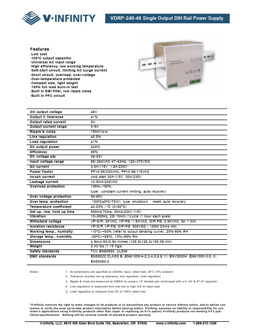
DC output voltage48V Output V.tolerance±1%Output rated current5A Output current range0-5A Ripple & noise150mVp-p Line regulation±0.5%Load regulation±1% DC output power240W Efficiency85% DC voltage adj.48-53V Input voltage range85~264VAC 47~63Hz; 120~370VDC AC current3.5A/115V 1.8A/230V Power FactorPF>0.95/230VAC, PF>0.98/115VAC Inrush currentcold start 30A/115V 50A/230V Leakage current<3.5mA/240VAC Overload protection105%~150%type: constant current limiting, auto recovery Over voltage protection54-60V Over temp. protection100ºC±5ºC(TSW) type: shutdown reset: auto recovery Temperature coefficient±0.03% / °C (0~50°C)Set up, rise, hold up time500ms;70ms; 30ms/230V,115V Vibration10~500Hz, 2G 10min./1cycle (1 hour each axes)Withstand voltageI/P-O/P: 3KVAC, I/P-FG: 1.5KVAC, O/P-FG: 0.5KVAC, for 1 min.Isolation resistanceI/P-O/P, I/P-FG, O/P-FG: 500VDC / 100M Ohms min.Working temp., humidity-10°C~+60% (refer to output derating curve), 20%-90% RH Storage temp., humidity-20ºC~+85ºC, 10%~95% RH Dimensions4.94x4.93x3.94 inches (125.5x125.2x100.08 mm) Weight2.43 lbs (1.10 Kgs) Safety standardsTUV EN60950, UL508EMC standards EN55022 CLASS B ,EN61000-4-2,3,4,5,6,8,11; ENV50204 ,EN61000-3-2,-3 ,EN50082-2Notes: 1. All parameters are specified at 230VAC input, rated load, 25°C 70% ambient2. Tolerance includes set up tolerance, line regulation, load regulation3. Ripple & noise are measured at 20MHz by using a 12” twisted pair terminated with a 0.1uF & 47 uF capacitor4. Line regulation is measured from low line to high line at rated load5, Load regulation is measure from 0% to 100% rated load*V-Infinity reserves the right to make changes to its products or to discontinue any product or service without notice, and to advise cus-tomers to verify the most up-to-date product information before placing orders. V-Infinity assumes no liability or responsibility for cus-tomer’s applications using V-Infinity products other than repair or replacing (at V-I’s option) V-Infinity products not meeting V-I’s pub-lished specifications. Nothing will be covered outside of standard product warranty.Features·Low cost·105°C output capacitor·Universal AC input range·High efficiency, low working temperature·Soft-start circuit, limiting AC surge current·Short circuit, overload, over-voltage·Over-temperature protected·Compact size, light weight·100% full load burn-in test·Built in EMI filter, low ripple noise·Built in PFC circuitDimensions (mm)。
迅磊变频器说明书说课讲解

迅磊变频器说明书目录一、前言 Introduction1、购入时注意事项 Checks upon Delivery2、HC系列铭牌说明 Nameplate Description of HC Series Inverter二、安全使用注意事项Safety Precautions1、送电前Before the Power-up)2、运转中During the Operation三、产品标准规格Standards and Specifications1、产品个别规格Particular Specifications2、产品通用规格General Specifications四、储存及安装Storage and Installation1、储存Storage2、安装场所及环境Installation Site and Environment3、安装空间与方向Installation and Direction五、配线 Wiring1、主回路配线图Main Circuit Wiring Schematic Diagram2、接线端子说明Description of Terminal Block3、基本配线图Basic Connection Diagram4、配线注意事项Precautions on Wiring六、数位操作器说明Instruction of the Digital Operator1、数位操作器说明Description of the Digital Operator2、显示项目说明Description of Indicator Lamp Status3、操作说明Description of Operation Examples七、试运行Commissioning1、运行前检查Important Checks before the Commissioning2、试运行方式Commissioning Methods八、功能一览表Function List九、功能说明Descriptions of Functions十、保养维护、故障信息及排除方法Care & Maintenance, Fault Information and Troubleshooting1、保养检查注意事项Precautions about Inspection and Maintenance2、定期检查项目Periodical Inspection and Maintenance items3、故障信息及排除方法Fault Indication and Troubleshooting4、故障及分析Faults and Analysis十一、周边设施选用及配置Selection of Peripheral Devices and Disposition1、选件Options2、配置Disposition十二、附录Appendice1、简单应用举例Simple Examples of Application一、 前言承蒙您惠顾HC 系列多功能,高性能通用变频调速器。
合康变频中低压选型样本
风机、水泵/水泥、陶瓷、玻璃生产线全线;
中央空调节能改造/空压机节能改造;
市政锅炉、污水处理;
部分拉丝机牵引;
矿井中的带式输送机、刮板运输机、给煤机、机油泵、油田的潜油电泵等;
......
叠层母排
HICONICS DRIVE TECHNOLOGY (WUHAN) CO.,LTD. 3.
绿色科技 造福人类
HICONICS DRIVE TECHNOLOGY (WUHAN) CO.,LTD.
卓尔不凡 超越无止境
该样本已经过认真的校对,但是仍然不能保证存在错漏之处,用户一旦发现请立即与合康变频科技(武汉)有限公司联系; 2wwHIwC.OhiNcIoC合nSic康Ds变.RcIo频VmE科T技E(CH武N汉OL)O有G限Y 公(W司U的HA目N标) C是O不.,L断TD追. 求科技进步,公司保留对该样本的修改权利,因此,样本中的部分内容可能会与实际产品稍有不同;
公司主导产品合康 HID 系列中、低压变频器均拥有自主 知识产权,已获得多项发明专利和实用新型专利。公司在能 量回馈 / 矢量控制技术、同步变频技术和大功率变频技术等方 面在国内居领先地位。产品广泛应用于火力发电、冶金、钢铁、 采油、矿山、建材、制药、纺织、化工、造纸、塑胶、机床、 起重、拉丝机、城市供水等行业和领域,主要对各类负载进 行调速、软启动和智能控制,不仅能提升工况效率,更具有 显著的节能效果,其不但能够极大提高客户产品的性能、工艺、 效率,更能为客户降低成本,有效提升客户核心价值。
6个数字输入端子,可扩展至10路,多达40种自定义功能,可兼容有源PNP输入或NPN输入;其中一路可 做高频脉冲输入(0~50kHz);2个模拟输入端子,可接收电压信号(0~10V)或电流信号(0~20mA); 可扩展至3路 0.4~1.5kW机型无扩展功能
DT1 DIN 轨浪涌保护 I+II 类 25 KA 模式 240 V 电缆保护设备说明书

CATALOG NUMBERDT130020RCERTIFICATIONSFEATURES紧凑、高浪涌额定可插拔设计,使用最小的 DIN 轨道宽度External back-up fuse is not required up to 315 A (IEC only)固定夹可确保提升抗振动和冲击性能采用红色/绿色状态指示和转换触点标准,实现远程监控产品属性Nominal System Voltage (Un): 240 VMax Continuous Operating Voltage (Uc): 300 VNominal Discharge Current (In), IEC: 20 kA 8/20 -sMax Discharge Current (Imax), IEC: 50 kA 8/20 -sImpulse Current (Iimp): 12.5 kA 10/350 μsVoltage Protection Level (Up): 1400 VResponse Time: 25 ns maxBack-Up Fuse @ Isccr: 250 A @ 50 kA A; 315 A @ 25 kA A Frequency: 50 – 60 HzShort Circuit Current Rating (Isccr): 25 kA; 50 kAProtection Modes: L-N; N-PETemporary Over Voltage 120 min (Ut/mode): 442 V 安全故障Temporary Over Voltage Withstand 5 s (Ut): 337 VVoltage Protection Rating (VPR): 900 VNominal Discharge Current (In), UL: 20 kA 8/20 -sReplacement Module: DT1300MShort Circuit Current Rating (SCCR): 150 kATechnology: 热断开Connection, Solid: 35 mm² maxConnection, Stranded: 25 mm² maxTorque: 4.5 N·mHumidity: 5 – 95Temperature: 从 -35 到 85 °CEnclosure Material: UL® 94V-0 热塑性塑料Enclosure Rating: IP 20Mounting: 35 毫米顶帽式 DIN 轨Remote Contact Switching Capacity: 0.5 A @ 12 VDC A; 0.5 A @ 24 VDC A; 0.5 A @ 48 VDC A; 1 A @ 125 VAC A; 1 A @ 250 VAC ARemote Contacts: 是Status Indication: 机械旗形组件Depth: 85 mmHeight: 90 mmWidth: 36 mmUnit Weight: 0.35 kgCertification Details: UL® 1449 版本 5 1CA 型Complies With: EN 61643-11 Type 1, Type 2; IEC® 61643-11 Class I, Class IIDIAGRAMS警告应仅根据 nVent 的产品说明书与培训材料安装并使用 nVent 的产品。
in4148中文资料_数据手册_参数
SEMTECH ELECTRONICS LTD.
Subsidiary of Sino-Tech International (BVI) Limited ®
Dated: 14/01/2013 Rev: 01
1N4148
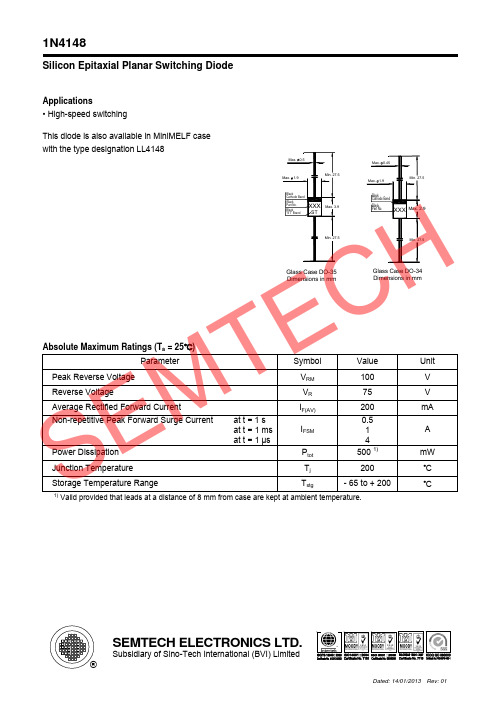
Admissible power dissipation versus ambient temperature
Max. 0.5 Max. 1.9
Min. 27.5
Max. 0.45 Max. 1.9
Min. 27.5
Black Cathode Band
Black Part No.
Black "ST" Brand
XXX
ST
Max. 3.9
Black Cathode Band
Black Part No.
XXX Max. 2.9
Reverse Recovery Time at IF = 10 mA to IR = 1 mA, Irr = 0.1 x IR, VR = 6 V, RL = 100 Ω
Thermal Resistance Junction to Ambient Air
Vfr
-
trr
-
RthA
-
Rectification Efficiency at f = 100 MHz, VRF = 2 V
ηV
0.45
1) Valid provided that leads at a distance of 8 mm from case are kept at ambient temperature.
4
2.5
4 0.35 1)
-
pF V
ns K/mW
CR型格兰富水泵说明书
图3 9 最小入口压力的计算方法:
4.9 尺寸和重量 尺寸:请参见第 69 页图 C。 重量:请参见包装上的标签。
4.10 噪音等级ຫໍສະໝຸດ 请参见第 30/31 页图 D。5.安装
泵必须用螺栓通过法兰孔或者泵座孔安全在可靠的坚实的基 础上。 在安装泵时,必须严格按照以下过程序进行操作,以免损坏泵。
步骤
安装方法
4.5 最大进口压力 第 27/28 页图 B 标示了进口最大压力。但是,泵入口压力加 泵在闭阀时的扬程必须低于最大允许压力。 应该如第 27/28 页图 B 所示,压力测试在所示压力的 1.5 倍 下进行。
4.6 最小流量 由于过热的危险,泵不应该工作在最小流量状态下。 下图显示在相应温度下,最小流量占正常流量的百分比。 虚线为空气冷却曲线顶点。
CR, CRI, CRN
安装与操作说明书
格兰富说明书
设计标准申明
我们格兰富公司申明:在我们销售的职责范围内,对于 CR,CRI 和 CRN 型号的产品,符合欧共体成员国试行法工作委员会指 令性文件,相关文件如下: —机械(98/37/欧共体).
采用标准:EN ISO 12100.[译者注:英语 国际标准 12100] —电磁相容性(89/336/欧洲经济共同体).
·安装有功率最大为 11kW 的格兰富 MG 电机的 CR,CRN 32,45,64,90 泵,应该通过提升泵端部的环状螺母来提升 泵。
·安装有功率在 15kW 以上的西门子电机的 CR,CRN 32,45, 64,90 泵,应该通过提升电机法兰上的的环状螺栓来提升泵。
·对于安装除上述之外的其它型号的电机的泵,建议用皮带等
在开始安装之前,应该仔细阅读如下安装和操作
说明。安装和操作也应该参照当地的有关法规或
表计
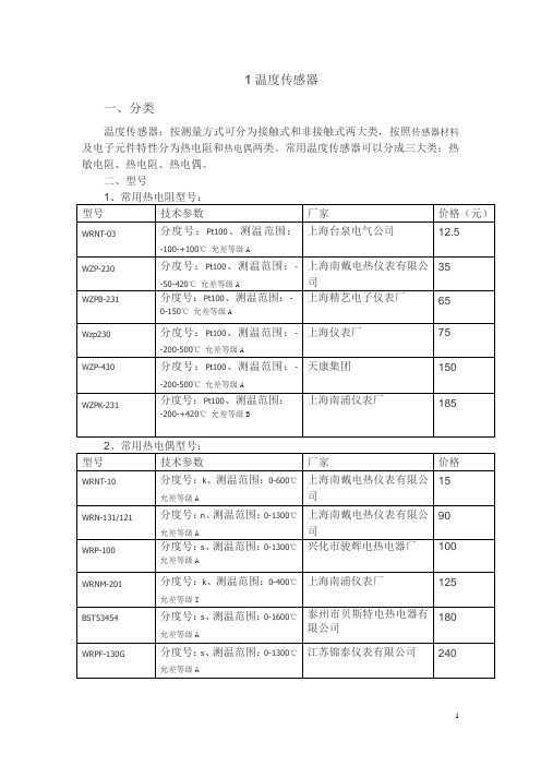
厂家
价格
金湖宏程自动化仪表有限 1000 公司
6
MRWJ-ZN
公称通径: 25 (mm) 、 工作温度: -40-50 (℃) 、工作压力:1.6(MPa) 、精确等 级:0.5、测量范围:1-800(m3/h)
宁波北仑明润船舶设备有 2000 限公司 济南昌润自动化仪表有限 1500 公司
CR-LF
LXS-15
技术参数
口径:15mm 旋翼式
厂家 上海沪光仪表厂 上海暖通阀门厂 上海暖通阀门厂 埃美柯 宁波牌
价格 23 21 37 228 370
LXS-20
口径:20mm 容积式
LXS-25
口径:25mm 容积式
LXS-C
口径:50mm
LXL-150
口径:150mm
YSDC20
口径:300mm
上海轶尚电子科技有限公 4536 司
重 庆 瑞 力 比 燃 气 设 备 有 95 限公司
G6/10/16/25/40/65
上海自动化仪表四厂
50
Y-100
表 盘 直 径 : 100mm 、 测 量 范 围 0-60mpa、精确等级:1.6 级、环境温 度:-4~70℃相对湿度不大于 85%、 使 用 温 度 偏 离 20 ± 5 ℃ 时 , 不 大 于 0.4%/10℃
上海减压器厂
52
2、精密压力表
型号
YB-150
技术参数
立新科技
550
DTSD710
额定电压: 3x220/380v 、额定电流: 3x1.5(6)A、 额定频率 50Hz、 计量精度: 有功 1 级无功 2 级、通讯:RS485 接口
友腾电器
650
3 压力表 一、分类
格兰富电子样本
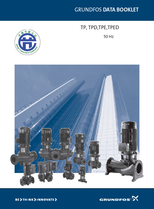
TP, TPD,TPE,TPED GRUNDFOS DATA BOOKLET 管道循环泵50 Hz目录产品数据引言3型号说明4轴封编码4性能曲线,2极5性能曲线,4极6性能曲线,6极7产品范围,2极10产品范围,4极12产品范围,6极14 TP100系列和TP200系列16 TP300系列/ TPE(D)1000系列17 TPE(D)2000系列18格兰富CUE19法兰21泵送液体22液体温度22泵送液体列表22结构电机24 EFF1标准电机的电气数据24 EFF2标准电机的电气数据26配有内置变频器的标准电机的电气数据27性能曲线,技术数据TP(D),TPE(D),2极28 TP(D),TPE(D),4极46 TP(D),TPE(D),6极67附件EMC滤波器71传感器72最小进口压力——净正吸入压头(NPSH)TP(D),TPE(D),2极73 TP(D),TPE(D),4极74 TP(D),6极74底板75泵型重量76节能认证说明7723引言TP 泵可用于如下系统:●区域供热系统●供热系统●空调系统●区域制冷系统●供水●工业生产工艺●工业冷却大多数泵均配有标准电机(TP 和TPD 型),同时还可以配置变频电机(TPE 和TPED )。
所有这些泵都是单级管道离心泵,配有标准电机和机械轴封。
泵是直联式结构,光泵和电机是独立的单元。
此类泵的分体结构比起相近类型的封闭转子结构来,更不容易受到泵送液体中杂质的影响。
这些泵均为顶部拉出式设计,也就是说,可以在不影响泵壳两侧的管路系统的情况下,对泵进行拆卸。
因此,即便是最大型号的泵,一个人也可以借助工具进行维修。
经ATEX 认证的TP 泵应要求,格兰富提供经ATEX 认证的TP 型和TPD 型泵。
所有经ATEX 认证的TP 泵均符合94/9/EC 指标(第二组,第3类)。
高效电机带有1.1kW 至90kW 功率电机的2极和4极TP 泵装配有高效电机(EFF 1)。
ZWS240PAF-24S中文资料(DENSEI-LAMBDA)中文数据手册「EasyDatasheet - 矽搜」

2 year warranty
型号名称
ZWS 100AF-5/
Series Name
Option
Output Power
Active Filter contained
Output Voltage
特征
marking (Low Voltage Directive) Active Filter contained, PFHC type Applicable to peakoutput wattage 120% (12V, 15V, 24V output) Low leakage current 0.5mA max Equipped with Remote ON/OFF control (with-cover type excluded) and output variable voltage 2 year warranty
产品阵容
Model name ZWS50AF ZWS75AF ZWS100AF ZWS150AF
ZWS50AF-5 ZWS50AF-12 ZWS50AF-15 ZWS50AF-24 ZWS75AF-5
ZWS75AF-12 ZWS75AF-15 ZWS75AF-24 ZWS100AF-5 ZWS100AF-12 ZWS100AF-15
芯片中文手册,看全文,戳
ZWS-AF -系列
单路输出50W〜150W
(Low Voltage Directive)
技术指标
1.输 入 电 压 范 围 2.功 率 因 数 3,输 出 电 压 范 围 4.冷 却 5.工 作 环 境
温度 (标准安装)
6.耐 压 7.安 全 标 准 8. CE标志 9. EMI 10.免 疫 11. PFHC 12.函 数
ADM2483BRW中文资料
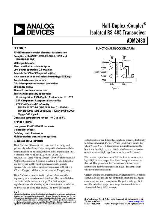
One Technology Way, P.O. Box 9106, Norwood, MA 02062-9106, U.S.A.
Tel: 781.329.4700
Fax: 781.326.8703 © 2004 Analog Devices, Inc. All rights reserved.
UL recognition: 2500 VRMS for 1 minute per UL 1577 CSA Component Acceptance Notice #5A VDE Certificate of Conformity
DIN EN 60747-5-2 (VDE 0884 Rev. 2): 2003-01 DIN EN 60950 (VDE 0805): 2001-12; EN 60950: 2000 VIORM = 560 V peak Operating temperature range: −40°C to +85°C
The receiver inputs have a true fail-safe feature that ensures a logic-high receiver output level when the inputs are open or shorted. This guarantees that the receiver outputs are in a known state before communication begins and at the point when communication ends.
APPLICATIONS
Low power RS-485/RS-422 networks Isolated interfaces Building control networks Multipoint data transmission systems
DR240数据采集器英文介绍资料
Bulletin 04M01D01-00E Data Acquisition and Recording WindowsHybrid RecorderAdvanced instrumentation technology for cost-effective datalogging and data acquisition.Data Acquisition and Recording WINdows for now and the future./tm/... and subscribe to “Newswave,”our free e-mail newsletterHighly Advanced, Versatile, 250 mm Hybrid Recorderthat Meets Your Present and Future Needs A highly reliable, functional expert tool-idealfor data acquisition and recordingHighly Expandable and Cost Effective DR240 Expandable Model 45DR240 expandable model The DR240 expandable model consists of a main unit, subunits, input/output and com-munications modules. Connecting the main unit to multiple subunits with dedicated ca-bles of up to 500 m total length, you can easily configure a recording/data acquisi-tion environment ranging from 10 to 300channels. Another key feature is its ability to scan up to 300 channels every 500 ms.You can also install one subunit on the back of the main unit of the hybrid recorder.Subunits (DS400, DS600)A subunit acts as an interface for connect-ing input modules to the main unit of the DR240 expandable model. There are two types of subunits, the DS400 which permitsconnection of up to four input and output modules, and the DS600 which permits con-nection of up to six input and output mod-ules.Normally, when a subunit is connected, itwill be at a separate location from the main unit.(When a subunit DS600 is mounted on the back of a main unit, a dedicated cable is required between them.)Alarm output module This is a 4-channel or 10-channel output module which outputs contact alarm signals according to preset conditions. You can set four alarm levels per channel (choose from upper limit, lower limit, delta high limit, delta low limit, or rate-of-change). You can install alarm output modules on the subunits.Input ModuleThe input module is a 10-channel* small remote multiplexer that A/D-converts the measured signals as fast as every 500 ms.** The input signals include not only DC voltage and temper-ature, but also contact, power monitor, pulse, strain and DCA (mA) signals.*:Power monitor modules are 2- or 6-channel.**:If input modules of different measurement intervals are mixed, the resulting measurement interval is that of the longest intervalinput module.● Universal Input Module The universal input module permits mea-surement of DC voltages between 20 mV and 50 V, thermocouple inputs, RTD inputs,and contact signals in up to 500-ms inter-vals.Other cost-effective universal input modules are available that measure data from 20 or30 channels in 2-second intervals, and low-cost dedicated input modules that accept voltages and thermocouple outputs.● Strain Measurement ModuleThe strain measurement module measures static strain, and comes in two types.One corporates a 120 or 350Ω bridge resistor,the other is for connecting an external bridge box. One module enables data in 10 channelsto be measured, however, it requires two slotsworth of space.The minimum measurement in-terval (data update cycle) is 500 ms.● Pulse Input Module The pulse input module receives TTL or con-tact signals from a flow or tachometer, and counts and integrates the number of puls-es. The minimum measurement interval is0.5 second and the data update cycle is one second.● Power Monitor Module The power monitor module receives AC volt-age or current input signals and measures RMS values, active power, apparent pow-er, reactive power, frequency, power factor and phase angle.The minimum measurement interval (data update cycle) is 2 seconds.Main unit (DR242)The DR242 acquires data measured by the input modules installed on each subunit,records the data in real time and/or trans-fers it to a PC using a general-purpose com-munications interface, and also stores it in a memory device.You can connect a communication module,Ethernet, RS -232C, RS -422/485 or GP-IB,and also a DI/DO module to the main unit.An input module, on a subunit (DS600), can be installed on the back of the main unit. A highly reliable, functional expert tool-ideal for data acquisition and recording General-purpose communications module You can connect a Ethernet, RS-422A/RS-485, RS -232C, or GP-IB general-purpose communications module to the back panel of the main unit. All measured data is trans-ferred in real time via the installed commu-nications module.DI/DO module This module enables the DR240 hybrid re-corder to be controlled* from a remote lo-cation, and also outputs the chart end and recorder fail signals to your external annun-ciator.*Remote control functions:Start and stop recording Change chart speed Start message printing Start and stop memory sampling Control statistical calculation interval The DR242 expandable model incorporates the fail and chart end output as standard features.● Direct Current (mA) Module The shunt resistor (100 Ω) is pre-installed tomeasure the DCA signal.Extension module Using an extension module, you can sup-ply power directly from a subunit for each input module*1, mounted on an extension base unit. Also, connecting an extension module on a subunit allows connection of up to three input modules as well as three extension base units, over a distance of up to 30 m.*1 :10-ch universal input module or 10-ch DCV/TC/DI input module Dedicated cableDedicated cableGeneral-purpose cable Dedicated cableDV250-001 Cable adapter The DV250-001 cable extension adapter is used as a junction terminal for extending a dedicated cable that connects betweenDARWIN units or as an adapter for connecting the dedicatedcable to a different cable.Dedicated cable ➑Ethernet Module The Ethernet module enables you to achieve high-speed, multi-channel, remote data com-munication via Ethernet. The module supports all commands generally used for DARWIN and permits data access from a max-imum of four personal comput-ers (configured to do so with user-created software).Example of an extension module and base units with DS400subunit6This model has a simple building block architec-ture, and comes with I/O and communications modules installed on the back of the main unit.Structural SimplicityDR240 Stand-alone ModelSpecify 10, 20 or 30 input channels, and desired options, at the time of ordering.Simple integrated construction You can connect 10, 20 or 30 channels directly to the main unit.The DR240 stand-alone model, which comes with I /O modules already in-stalled, is a cost-effective general-pur-pose model.The external appearance, recorder function, memory and communications functions of this model are identical to those of the expandable model. Be-cause this model is of integrated con-struction, it can be carried about easily.Universal and power monitor range Universal inputs permit measurement of a variety of inputs including DC voltage,thermocouple, RTD and contact signals.Low-cost model for measuring only voltage and thermocouple signals is available. You can also select power monitor (optional) for measuring AC voltage and current.Variety of options, including gen-eral-purpose communications and DI/DO functionsGeneral-purpose communications (Eth-ernet, RS-232C, RS-422A/485, and GP-IB), 10-point SPDT alarm output relays,DI/DO (2 alarm relays, remote control of recorder, CPU fail and chart end con-tacts).Specify your required options when or-dering.Rear panel of the stand-alone modelAC or DC power terminal7Versatile Operator Display and Ease of Operation Monitoring/Configuration FunctionsThe DR240 incorporates a 3-line, large vacuum flu-orescent display (VFD) which can be used as a pro-cess monitor enabling you to readily view data or check alarm statuses, even from a remote location.The DR240 is interactively configured using the easily-read display.Versatile display formatsThe large vacuum fluorescent display shows a total of 102 char-acters, one line of 22 large characters, and two lines of 44smaller characters.It displays the measured results and alarm statuses in an eas-Simple setupThe DR240 is interactively configured using the 102 character VFD display. The setup items are always displayed in large characters at the top, with the range of choices and other in-formation displayed at the bottom.In addition, the setup menus separate items that are frequent-ly used from those that are rarely changed once set, thus sim-plifying configuration.ily readable format. There are a large number of display for-mats including up to 5-ch digital data, bar graph, and alarm relay status. Tag names and engineering units are displayed,making process monitoring easier than ever.Input range and span configuration menuReplacing consumables The ink ribbon is a quickly replaceable cassette. Also, the chart holder is a pull-out type enabling the chart to be replaced with ease.The ink ribbon and chart paper are completely interchange-able with the ribbon and paper used in YOKOGAWA's HR2400hybrid recorder.Removable input/output modulesThe input and output sections are of modular construction,enabling them to be removed when performing wiring. Also,the universal input modules are available with either screw or push-in (clamp) type terminals.Chart speed setup menu8Clear Hybrid Recording FunctionsA recorder's performance is measured by the read-ability of the information on its printed chart. TheDR240 can record clearly, in 10 colors, data fromall measurement points, at 2-second intervals. Ithas a wide variety of recording functions includinganalog trend recording over an effective recordingwidth of 250 mm, recording of digital measuredvalues, recording of various messages, zone re-cording, and partially compressed and expandedrecording, that help interpret the data.● High speed recording at 2-second intervals● Programable ten-color recording● Versatile recording formatsThe interpolation function enables data points of each channel to be linked by lateral line segments soas to show the continuity of the data.9PC-FriendlyData Acquisition Software is designed to run under Windows 98/Me/NT4.0/2000/XPIn addition to performing real time recording in the field and saving measured data to a removable memory media, the DR240 functions as a PC based high speed multi-point data acquisition unit.Various kinds of application software are available.Software for configuration and data acquisition, and software for converting data saved to a removable memory device, is available. This application soft-ware makes your tasks of configuration and data acquistion quick and easy.DARWIN DAQ32 SoftwareDARWIN DAQ32Plus SoftwareThe data acquisition software 32PLus (DAQ32Plus) is the en-hanced software for common use with all the data gathering instruments in the DARWIN series. Like the standard DAQ32,this software includes hardware setup, simplified data logging,simplified data viewing, data conversion (Excel, Lotus 1-2-3or ASCII format), preference setting, system diagnosis, cali-bration, and tag number setting functions, all in one package.DAQ32Plus is far more powerful than DAQ32, however, in terms of the data monitoring and logging functions. It contains a number of additional functions not found in DAQ32. Additions include a display of up to 30 data groups each having a max-imum of 32 channels' worth of data per window (as compared with the DAQ32's display of up to 2 data groups each having a maximum of 10 channels' worth of data per window); dis-plays of various meters including level meters, analog meters and thermometers (not offered by DAQ32); alarm displays; as well as a DDE server, logger autostart, retry, password and tag setting function.Example of hardware setup displayThe data acquisition software 32 (DAQ32) is the standard soft-ware for common use with all the data gathering instruments in the DARWIN series. The software includes hardware setup,simplified data logging, simplified data viewing, data conver-sion (Excel, Lotus 1-2-3 or ASCII format), preference setting,system diagnosis and calibration functions, all in one pack-age. All models of the DA100 data acquisition unit and DC100data collector come standard with this software. For each model of the DR130, DR230 and DR240 hybrid data record-ers, you can specify whether software is necessary or unnec-essary when ordering. When you specify software as "neces-sary," DAQ32 software comes standard with the model.Example of date logging displayExample of date viewing display10The DR240 provides many economic benefits forthe user, such as reduced wiring for remote mea-surement, space saving due to compact design,and optimized signal conversion costs due to theavailability of a large variety of input modules.Max. 500 ms/300 channel highspeed measurement (expand-able model)Parallel processing of data is used bythe dedicated A/D converter inside eachinput module. 1 Mbps high speed datatransfer is accomplished between themain unit and each subunit. Further-more, the use of a distributed multi-CPUcontrol method for the overall systemachieves high speed measurement ofdata from 300 channels over an intervalof 500 ms. The DR240 has a time axisresolution four times that of the previ-ous model (DA2500E), achieving bettertime synchronization between channels.Space saving due to compactdesignThe depth of the main unit of the DR240hybrid recorder has been greatly re-duced: it is about 60%* of previousmodels in the case of the 60-channelmodel, and about 80%** in the case ofthe 30-channel general-purpose mod-el. Also, the use of high breakdown volt-age solid state relays and a planar trans-former developed by YOKOGAWA hasenabled the volume of the 60-point in-put remote measurement section to bereduced to 1/5*** of that of previousmodels, resulting in a highly compactunit. The mass of the unit has also beenreduced to about 1/2*. This makes formore efficient use of control room or lab-oratory space and reduces toal costs.*Compared to YOKOGAWA's HR2500E, in-cluding the input measurement section**Compared to YOKOGAWA's HR2400, in-cluding the input measurement sectionIn addition, it provides superb environmental rug-gedness, and onboard computation and memoryfunctions, enabling it to be used for a wide rangeof applications.Application Versatilityules are installedDA2500E remote scanner11Computing functions The main unit of the DR240 with option-al MATH feature can perform the four arithmetic operations, integration of measured data, and computations such as detection of maximum and minimum values, in realtime. Even without the optional feature, the DR240 can com-pute linear scaling, difference and mov-ing average. The results of such com-putations are transferred with the mea-sured data to a PC, thus reducing sys-tem requirements on the PC and also resulting in more efficient analytical pro-cessing.The main computing functions are as follows. (The shortest computation peri-od differs depending on the kind of com-putation.)Standard computing functions Linear scaling, moving average, differ-ential calculation, pulse integration (when a pulse input module is recognized)Optional functions The four arithmetic operations, logic operations, related operations, calcula-tion of absolute and relative values, and statistical calculations (maximum, mini-mum, mean, and integrated values for fixed intervals)Report function (/M3)You can calculate the maximum, mini-mum, average values, and integrated value of the measured results, and print hourly, daily and monthly reports. The calculated values are also recorded in the report results.Memory function You can select a floppy disk function with 512 kB SRAM capability for stor-age of information on a removable me-dia. You can save several configura-tion setups and in addition store themeasured data before and after analarm, and also calculated values.You can record the memorized data on DR240 chart, transfer it off-line to a PC,or analyze it or make it into a report us-ing commercially available spreadsheet software.●You can save the measured data in the following cases:•By manual command or when a com-munications command is input •When an alarm is detected •When the end of the chart is reached ●The save modes are as follows:•Single: Data of the specified length is sampled once only.•Repeat: Data of the specified length is sampled exactly the number of times specified in advance.*When measured values are saved to a flop-py disk, they are first stored in the buffer memory (512 kB DRAM).By using the DR240 in combination with the optional DI/DO module or alarm function, you can easily perform batch processing.● Moving average functionThis function renews the measured val-ue while calculating the moving average,is effectively monitoring the trend of a varying input signal over a long period.It can also be used as a digital filter when noise components are present on the input signal. You can set the number of moving average scans by selecting avalue between 2 and 64.12High breakdown voltage solidstate relay (SSR)Developed by YOKOGAWA, the SSRswitches the inputs when performingmulti-channel measurement. A semi-conductor device takes the place of thecontacts and drive part of a mechani-cal relay, thus overcoming the problemof defective measurement caused byfaulty or worn contacts of the mechani-cal type relay. YOKOGAWA's solid staterelay has a high breakdown voltage(1500 VDC), enhancing safety in thefield. Also, its low leakage current (1nA) enables the very low level voltagesignals from a thermocouple to be mea-sured with high accuracy.YOKOGAWA currently uses this SSR inits hybrid recorders and the advancedµR series of industrial recorders. Over800 thousand channels of this technol-ogy have performed successfully in var-ious field and laboratory applications,thus verifying the reliability of the relaydevice.A new surface-mounted version of thishighly reliable SSR is used in the DAR-WIN family.This permits a high degree of miniatur-ization, low power consumption, longdevice life and quiet operation.Increased ReliabilityYOKOGAWA has Continually Improved its Measurement Technology for Your BenefitThe history of YOKOGAWA in strip chart recordinginstruments can be summarized as the provisionof the world's most reliable and readable record-ers, with unmatched performance, over the last fif-teen years. In 1981, YOKOGAWA developed theModel 4088 hybrid recorder which was the first dotprinting type recorder in the world to contain a mi-croprocessor. Since then, we have continued tomake many technical breakthroughs, including thenon-contact ultrasonic position detector, and highbreakdown voltage (HBV) solid state relay, bring-ing multipoint recording closer to perfection.This commitment to you is also evident in theDR240 hybrid recorder, which uses YOKOGAWA'sadvanced technologies to help you achieve higherreliability and compactness, and improved PC-com-patibility.Planar transformerA planar transformer is a revolutionaryintegrated transformer which takes theplace of the conventional wire-woundtransformer, the most antiquated of allelectronic components. This small, thintransformer consists of multi-layer pre-cision thin film coils, enhancing insula-tion, and also reducing heat and noiseemission. This concept design meansthat the power supply unit occupies just1/2 to 1/4 of the volume of conventionalunits.All of the transformers in the main unit,subunits and input and output modulesof the DR240 are planar transformers.This is an important factor in achievingthe large degree of miniaturization andweight reduction of the DR240.Adoption of ASICsThe DR240 uses ASI Cs (ApplicationSpecific Integrated Circuit) which weredeveloped with more than 40 years ofdata acquisition know-how accumulat-ed by YOKOGAWA. Moreover, a highdegree of integration has been attainedby gate arrays, used around the A/Dconverter, communication interface, re-cording and display control circuits. Asa result of this high degree of integra-tion, the DR240 has become smaller andlighter, and power consumption andheat generation reduced, improving thereliability of the overall system.Advanced carriage driveThe carriage drive section of the dotprinter head employs a screw shaftwhich is unique for a strip chart record-er. The drive belt and wire cable havebeen removed, resulting in increasedreliability.Integration of the design, manu-facture and quality evaluationsystemRoutine installation work is automated,preventing careless mistakes during theproduction process from assemblythrough inspection. The result is a highgrade, highly reliable product.We also use precision test equipmenton the production line to further increasereliability.Supported standardsCSAULCEC-TickObtained CSA22.2 No.1010.1,Installation category (Overvoltagecategory): II, Degree of pollution: 2Obtained UL3111-1 (CSA NRTL/C)EMCdirectiveLow voltagedirectiveAS/NZS 2064 Class A Group 1EN61326EN61000-3-2EN61000-3-3EN55011 Class A Group 1EN61010-1Measurement category: II,Degree of pollution: 213SpecificationsHz) and 100 ms (10 Hz)Minimum measurement interval when the 100-ms integration mode becomes:DR241:30 channels; 6 seconds●Number of Recording Points300 points maximum (stand-alone model: 30 points + AC 6 points)●Recording PaperEffective recording width :250 mm (for analog trend measurement)●Analog recording color (You can specify a color for each channel.)Purple, red, green, blue, brown, black, navy blue, yellow-green, red-purple,orange●Analog Recording Interval FIX:Recording takes place at the specified measurementinterval between 2 and 60 seconds (not all measured values are sampled for analog recording in case of the 0.5- and 1-second measurement intervals)AUTO:Linked to recording paper feed speed ●Recording Paper Feed Paper feed speed: 1 to 1,500 mm/hour Display Section ●Display Section Display:VFD display (5 x 7 dot matrix, 3 lines)Number of characters:22 characters (large/1 line), 40 characters (2 lines)Memory Function Section ●Memory Media3.5-inch floppy disk drive with 512 kB SRAM buffer memory ●Data Capacity10 data/ch to 50 kdata/ch(Total data memory should be less than total memory length.)●Applicable dataSetting values, measurement values and computed values except report calculating values ●Memory Mode BinaryCan be converted to ASCII (CSV) format for copying buffer memory data to floppy disk ●Sample RateSynchronized with the measurement interval of the recorder unit, or synchronized with event.Alarms●Number of SettingsUp to four settings can be made for each channel.●Kinds of AlarmsUpper/lower limit, difference upper/lower limit, upper/lower limit of percentage change, upper or lower limit only for the results of computation Percentage change alarm time interval: 1 to 15 scans ●Number of Alarm Output Points DR241:12 maximum (alarm option: 10; DI/DO option: 2)DR242:300 in total Standard Computation Functions ●Kinds of ComputationDifference between arbitrarily selected channels, linear scaling, moving average,pulse integrationScalable range:DC voltage, thermocouple, RTD, contact Scaling range:–30,000 to +30,000Moving average: 2 to 64 scans Pulse integration:Effective when a pulse input module is recognized(up to 60 channels)Fail, Chart End Output(DR expandable model. The DR stand-alone model uses the /R1 option.)Functions:Refer to the DI / DO modules.●Number of Computation Channels DR241:30 channels maximum DR242:60 channels maximum ●KindsRemote RJC, four arithmetic operations, SQR (square root), ABS (absolute value), LOG (common or natural logarithm), EXP (exponential), statistics processing (CLOG, TLOG), logic (AND, OR, NOT, XOR), relative computation,previous data reference.CLOG:Mathematical processing within a group of data thatwas measured at the same time (total, maximum,minimum, average, max. - min.)TLOG:Mathematical processing of data from a certainchannel over a period of time (24 hours maximum)(total, maximum, minimum, average max. - min.)Report Function (/M3)Instantaneous values of measured data, as well as maximum, minimum, average and total, for each hour, day or month are printed in tabular form on recording paper. Analog recording is interrupted while a report is being made.Report calculation channels :Up to 60 channels Note:This function does not allow the results of the reportand computing function to be saved on floppy disks.(Thus, to be able to transfer the results to a personal computer, the DP380 report software is needed.Note that the DP380 software cannot be run simultaneously with the DAQ32 or DAQ32Plus software package.)Power Monitor Options (/N7, /N8)●Applicable models and outline specificationsDR241 stand-alone model (For the DR242, the power monitor module is sold separately.) Refer to the power monitor module.GP-IB Communications Option (/C1)●Applicable models and outline specificationsDR241 stand-alone model (For the DR242, the GP-IB module is sold separately.)Refer to the GP-IB module.●External Dimensions; Weight (with I/O module installed)DR241:approximately 444 (W)×288 (H)×343 (D) mm; approximately 16 kg DR242:approximately 444 (W)×288 (H)×308 (D) mm; approximately 12 kg DS400:approximately 336 (W)×165 (H)×100 (D) mm; approximately 2.5 kg DS600:approximately 422 (W)×176 (H)×100 (D) mm; approximately 3.5 kg ●AC Power Supply Rated supply voltage:100 to 240 VAC Usable supply voltage:90 to 250 VAC Rated supply frequency:50/60 Hz●DC power supply (Runs on a DC power supply only. Specify when ordering.)Rated supply voltage:12 to 28 VDC Usable supply voltage:10 to 32 VDC Terminal:Screw terminals ●Insulation ResistanceAt least 20 M Ω at 500 VDC between the power supply and ground, between each terminal and the ground, and between input terminals ●Withstanding VoltageBetween power supply terminal and ground:1,500 VAC (50/60 Hz, 1 min.)Between input/output terminal and ground:1,500 VAC (50/60 Hz, 1 min.)●Normal Operating Conditions Supply frequency:50 Hz ±2% or 60 Hz ±2%Ambient temperature:DR241, DR242 0 to 50˚C (FD operation 5 to 40˚C)DS400, DS600Panel mount –10 to 60˚CDesk-top –10 to 50˚CAmbient humidity:20 to 80% RH (between -10 and 40˚C)●Safety StandardsCSA C22.2 No.1010.1-92, IEC1010-1:1995, EN61010●EMI StandardEN55011:1991, Group 1 class A ●EMC Standard EN50082-2:1995System Configuration ●Configuration Method DR241:Configure a system with this model by specifying necessary options, such as the input and communications functions, according to the model code when ordering.DR242:Configure a system with this model by combining one or more of the modules and subunits listed below.Connecting Modules and Subunits (DR242)●Standard Modules and Software for System ConfigurationThe following modules and software can be installed in a main unit and subunit to configure a data acquisition system.Input Modules:Universal (DCV, TC, RTD and DI), DCV/TC/DIdedicated, power monitor, strain, pulse, direct current (mA) and digital input modules Connectable to DS400 and DS600Communications Modules :Eternet, GP-IB, RS-232C and RS-422A/485Connectable to DR242 main unitAlarm Contact Output Modules: 4 contacts (SPDT: NO-C-NC) and 10 contacts (makecontact: NO-C).Connectable to DR242 main unit or DS400 and DS600DI/DO Modules:Two alarm output contacts (NO-C-NC) and fail outputConnectable to DR242 main unit or DS400 and DS600Up to 1 module/1 system can be connected.Extension Modules:Interfaces for remote power supplyOne extension module can be connected to each DS400 and DS600.(should be used with extension base units)Software:DAQ32 (Stardard software)DAQ32 plus (Optional software)●Types and Number of Modules That Can Be Connected DR241:Specify the types of modules and the numberaccording to the model code.DR242:Communications module DI/DO module or alarmcontact output moduleDS400/600Input module, alarm contact output modules, DI/DOmodules and extension modulesFour or six modules can be connected.●Connection of Subunits DR241:Cannot be connected.DR242:Up to 6 subunits can be connected. One subunit canbe installed on the rear panel by screws.Input Section●Number of Input Channels DR241:10 to 30 channels (Specify the number of channelswhen ordering)Power monitor input option: 2 or 6 channelsDR242:0 channel. Expandable up to 300 channels byconnecting subunits.●Types of Input Modules DR241:Universal (DC voltage, thermocouple, RTD andcontact), DCV/TC/DI dedicated (Specify the types when ordering), power monitor optionDR242:Universal (DC voltage, thermocouple, RTD andcontact), DCV/TC/DI dedicated, power monitor,strain, pulse, direct current (mA) and digital input modules●Measurement Range:See the specifications for each input module.●Measurement Interval:0.5, 1, 2, 3, 4, 5, 6, 10, 12, 15, 20, 30 and 60 seconds DR241:Maximum of 2 s per 30 channels DR242:Maximum of 500 ms per 300 channels (including thesubunit)The measurement interval is dependent on the slowest input module if input modules of different measurement intervals are connected at the same time.●A/D Integration PeriodManual selection or automatic switchover between 20 ms (50 Hz), 16.7 ms (60。
IRFP240A中文资料

Value Units A V mJ A A V TO-3P1.Gate2. Drain3. Source3212002012.7802672030 +_TRADEMARKSACEx™CoolFET™CROSSVOLT™E 2CMOS TM FACT™FACT Quiet Series™FAST ®FASTr™GTO™HiSeC™The following are registered and unregistered trademarks Fairchild Semiconductor owns or is authorized to use and is not intended to be an exhaustive list of all such trademarks.LIFE SUPPORT POLICYFAIRCHILD’S PRODUCTS ARE NOT AUTHORIZED FOR USE AS CRITICAL COMPONENTS IN LIFE SUPPORTDEVICES OR SYSTEMS WITHOUT THE EXPRESS WRITTEN APPROV AL OF FAIRCHILD SEMICONDUCTOR CORPORA TION.As used herein:ISOPLANAR™MICROWIRE™POP™PowerTrench™QS™Quiet Series™SuperSOT™-3SuperSOT™-6SuperSOT™-8TinyLogic™1. Life support devices or systems are devices or systems which, (a) are intended for surgical implant intothe body, or (b) support or sustain life, or (c) whosefailure to perform when properly used in accordancewith instructions for use provided in the labeling, can be reasonably expected to result in significant injury to the user.2. A critical component is any component of a lifesupport device or system whose failure to perform can be reasonably expected to cause the failure of the life support device or system, or to affect its safety or effectiveness.PRODUCT STATUS DEFINITIONS Definition of Terms Datasheet Identification Product Status DefinitionAdvance InformationPreliminary No Identification Needed Obsolete This datasheet contains the design specifications for product development. Specifications may change in any manner without notice.This datasheet contains preliminary data, andsupplementary data will be published at a later date.Fairchild Semiconductor reserves the right to make changes at any time without notice in order to improve design.This datasheet contains final specifications. Fairchild Semiconductor reserves the right to make changes at any time without notice in order to improve design.This datasheet contains specifications on a product that has been discontinued by Fairchild semiconductor.The datasheet is printed for reference information only.Formative or In DesignFirst ProductionFull ProductionNot In ProductionDISCLAIMERFAIRCHILD SEMICONDUCTOR RESERVES THE RIGHT TO MAKE CHANGES WITHOUT FURTHER NOTICE TO ANY PRODUCTS HEREIN TO IMPROVE RELIABILITY , FUNCTION OR DESIGN. FAIRCHILD DOES NOT ASSUME ANY LIABILITY ARISING OUT OF THE APPLICATION OR USE OF ANY PRODUCT OR CIRCUIT DESCRIBED HEREIN; NEITHER DOES IT CONVEY ANY LICENSE UNDER ITS PATENT RIGHTS, NOR THE RIGHTS OF OTHERS.UHC™VCX™。
240R中文资料
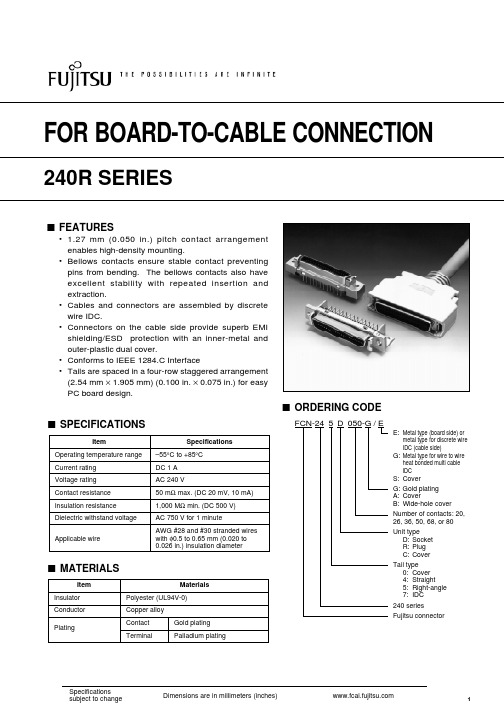
FOR BOARD-TO-CABLE CONNECTION240R SERIESs FEATURES• 1.27 mm (0.050 in.) pitch contact arrangement enables high-density mounting.•Bellows contacts ensure stable contact preventing pins from bending. The bellows contacts also have excellent stability with repeated insertion and extraction.•Cables and connectors are assembled by discrete wire IDC.•Connectors on the cable side provide superb EMI shielding/ESD protection with an inner-metal and outer-plastic dual cover.•Conforms to IEEE 1284.C Interface•Tails are spaced in a four-row staggered arrangement (2.54 mm × 1.905 mm) (0.100 in. × 0.075 in.) for easy PC board design.s SPECIFICATIONSSpecifications–55°C to +85°C DC 1 A AC 240 V50 m Ω max. (DC 20 mV, 10 mA)1,000 M Ω min. (DC 500 V)AC 750 V for 1 minuteAWG #28 and #30 stranded wires with φ0.5 to 0.65 mm (0.020 to 0.026 in.) insulation diameterItemOperating temperature range Current rating Voltage rating Contact resistance Insulation resistance Dielectric withstand voltage Applicable wireMaterialsPolyester (UL94V-0)Copper alloy Contact Terminals MATERIALSItemInsulator Conductor PlatingGold plating Palladium platings ORDERING CODEFCN-245D 050-G /EE:Metal type (board side) or metal type for discrete wire IDC (cable side)G:Metal type for wire to wire heat bonded multi cable IDC S:CoverG:Gold plating A:CoverB:Wide-hole cover Number of contacts: 20,26, 36, 50, 68, or 80Unit type D:Socket R:Plug C:Cover Tail type 0:Cover 4:Straight 5:Right-angle 7:IDC 240 seriesFujitsu connector240R SeriesSTRAIGHT SOCKET s DIMENSIONSs MOUNTING HOLE LAYOUT (COMPONENT SIDE)s PATTERN INHIBITED AREASs RECOMMENDED PANEL DIMENSIONSs PART NUMBERS AND DIMENSIONSNumber of contacts202636506880Part number FCN-244D020-G/E FCN-244D026-G/E FCN-244D036-G/E FCN-244D050-G/E FCN-244D068-G/E FCN-244D080-G/EA 11.43 (0.450)15.24 (0.600)21.59 (0.850)30.48 (1.200)41.91 (1.650)49.53 (1.950)B 13.45 (0.529)17.26 (0.679)23.61 (0.929)32.50 (1.279)43.93 (1.729)51.55 (2.029)C 16.45 (0.647)20.26 (0.797)26.61 (1.047)35.50 (1.397)46.93 (1.847)54.55 (2.147)D 27.45 (1.080)31.26 (1.231)37.61 (1.480)46.50 (1.830)57.93 (2.280)65.55 (2.580)E33.35 (1.312)37.16 (1.462)43.51 (1.712)52.40 (2.062)63.83 (2.512)71.45 (2.812)F 23.30 (0.917)27.11 (1.067)33.46 (1.317)42.35 (1.667)53.78 (2.117)61.40 (2.417)Unit: mm (in.)240R Series© 2005 Fujitsu Components America, Inc. All company and product names are trademarks or registered trademarks of their respective owners. Rev. 01/17/2005.JapanFujitsu Component Limited Gotanda-Chuo Building3-5, Higashigotanda 2-chome, Shinagawa-ku Tokyo 141, Japan Tel: (81-3) 5449-7010Fax: (81-3) 5449-2626Email: promothq@ Web: North and South AmericaFujitsu Components America, Inc.250 E. Caribbean DriveSunnyvale, CA 94089 U.S.A.Tel: (1-408) 745-4900Fax: (1-408) 745-4970Email: marcom@ Web: EuropeFujitsu Components Europe B.V.Diamantlaan 252132 WV Hoofddorp NetherlandsTel: (31-23) 5560910Fax: (31-23) 5560950Email: info@ Web: Asia PacificFujitsu Components Asia Ltd.102E Pasir Panjang Road#04-01 Citilink Warehouse Complex Singapore 118529Tel: (65) 6375-8560Fax: (65) 6273-3021Email: fcal@ Fujitsu Components International Headquarter Offices。
MAX5048BAUT中文资料

Note 1: Continuous output current is limited by the power dissipation of the package. *As per JEDEC51 standard.
Stresses beyond those listed under “Absolute Maximum Ratings” may cause permanent damage to the device. These are stress ratings only, and functional operation of the device at these or any other conditions beyond those indicated in the operational sections of the specifications is not implied. Exposure to absolute maximum rating conditions for extended periods may affect device reliability.
♦ +4V to +12.6V Single Power Supply ♦ 7.6A/1.3A Peak Sink/Source Drive Current ♦ 0.23Ω Open-Drain n-Channel Sink Output ♦ 2Ω Open-Drain p-Channel Source Output ♦ 12ns (typ) Propagation Delay ♦ Matching Delay Time Between Inverting and
For pricing, delivery, and ordering information, please contact Maxim/Dallas Direct! at 1-888-629-4642, or visit Maxim’s website at .
施耐德电子行业有限公司产品数据表1000VA 240 480V-24V行业控制变压器说明书

Package 1 Height Package 1 width Package 1 Length
1 phase 1000 VA UL 1000 VA CSA 1000 VA NOM 630 VA 240 x 480 V 24 V 115 °C Screw clamp terminals 4.51 in (114.55 mm) 5.25 in (133.35 mm) 6.3 in (160.02 mm) Copper winding FSC2
8.50 in (21.590 cm) 11.00 in (27.940 cm) 10.00 in (25.400 cm)
Jul 7, 2020
1
Offer Sustainability
Sustainable offer status REACh free of SVHC EU RoHS Directive Toxic heavy metal free Mercury free RoHS exemption information China RoHS Regulation Environmental Disclosure PVC free
2
Contractual warranty
Warranty
Green Premium product Yes
Compliant Yes Yes
EU RoHS Declaration
Yes
China RoHS Declaration
ห้องสมุดไป่ตู้
Product Environmental Profile Yes
10 Years
Industrial Control Transformer
- 1、下载文档前请自行甄别文档内容的完整性,平台不提供额外的编辑、内容补充、找答案等附加服务。
- 2、"仅部分预览"的文档,不可在线预览部分如存在完整性等问题,可反馈申请退款(可完整预览的文档不适用该条件!)。
- 3、如文档侵犯您的权益,请联系客服反馈,我们会尽快为您处理(人工客服工作时间:9:00-18:30)。
Conditions Conditions
Input / Output Input / Output, @ 500VDC Operating at Vi nom Vi nom, from +61 to +71 C Non operational Vi nom, Io nom Screw terminal type Detachable connector type Free air convection Metal
115 / 230 VAC 115 / 230 VAC
OUTPUT OUTPUT WATTAGE VOLTAGE Single Output Models
240 WATTS 240 WATTS + 24 VDC + 48 VDC
OUTPUT CURRENT
10A 5A
EFF. (min.)
87% 88%
CONTROL AND PROTECTION
Characteristics
Input fuse Rated over load protection Power Rdy (for 24V model only) Vi nom
Threshold voltage of contact closed(at start up) Electrical isolation Contact rating at 60VDC
WEIGHT
1100g
2008.09.23
sales@
元器件交易网
DRA240 SERIES
MECHANISM & PIN CONFIGURATION
mm [inch]
CONSTRUCTION
83 [3.27]
6 1
83 [3.27]
EFF. (typ.)
89% 90%
SPECIFICATION
All Specifications Typical At Nominal Line, Full Load, 25oC Unless Otherwise Noticed
GENERAL
Characteristics
Isolation voltage Isolation resistance Ambient temperature Derating Storage temperature Relative humidity Dimension Cooling Case material
typ.
max.
132 264 370
unit
VAC VAC VAC VDC A Hz A A
115 / 230(auto select)
Rated input current Line frequency Inrush current P F. C. .
Io nom Vi nom, Io nom Vi nom, Io nom Vi : 230VAC, Io nom Vi : 115VAC Vi : 230VAC 47
DC LO DC ON
S P
- - ++ Rdy
Vout ADJ.
123.6 [4.87] 142 [5.59]
DC LO DC ON
INSTALLATION
Ventilation / Cooling Normal convection All sides 25mm free space For cooling recommended Connector size range Screw terminal: 10-24AWG flexible / solid cable, 8 m/m stripping at cable end recommends Detachable connector: 14-24AWG flexible / solid cable, 7 m/m stripping at cable end recommends
min.
-0 0
typ.
max.
+ 1 0.5 1 5 0.02 100
unit
% % % % % % / oC mV ms ms
Minimum load Line regulation Load regulation Temperature coefficient Ripple & noise Hold up time Voltage trim range
120 Current limited
145
2008.09.23
sales@
元器件交易网
DRA240 SERIES
SPECIFICATION
All Specifications Typical At Nominal Line, Full Load, 25oC Unless Otherwise Noticed
5.4 / 2.2 63 30 60 0.7
OUTPUT SPECIFICATIONS
Characteristics
Output voltage accuracy
(Adjusted before shipment)
Conditions
Vi nom, Io max Vi nom Io nom, Vi min ...Vi max Vi nom, Io min ...Io nom Vi nom, Io min Vi nom, Io nom,BW = 20MHz Vi nom, Io nom Vi nom, Io nom Vi nom, Io nom Vi nom, Io nom 0.9 Io max Vi nom, Io nom, Po / Pi Vi = 115VAC Vi = 230VAC 24V models 48V models 24V models 48V models 24V models 48V models single mode parallel mode
16 25 30 22.5 47 17.6 37 17.6 37 Up to 90%, See model list 28.5 56 19.4 43 19.4 43 3
VDC VDC VDC VDC VDC VDC unit
DC ON indicator threshold at start up DC LOW indicator threshold after start up Parallel operation Efficiency
CIRCUIT SCHEMATIC
Block diagram for DRA240 series
L Fuse Filter N Y
Inrush Current Limiter, Rectifier and Auto Select 115 / 230 Vac
Vo + P. F. C. Circuit
Smoothing Circuit Switching
sales@
元器件交易网
DRA240 SERIES
SPECIFICATION
All Specifications Typical At Nominal Line, Full Load, 25oC Unless Otherwise Noticed
INPUT SPECIFICATIONS
116.6 [4.59]
7.0 [0.3]
Easy snap-on mounting onto the DIN-Rail (TS35/7.5 or TS35/15), unit sits safeIy and firmly on the rail.
6
1
S P
- - ++ Rdy
Vout ADJ.
123.6 [4.87]
元器件交易网
DRA240 SERIES
AC - DC DIN RAIL MOUNTABLE 240W INDUSTRIAL CONTROL EQUIPMENT
FEATURES
COMPACT DESIGN HIGH EFFICIENCY UP TO 90% P .F.C. FUNCTION AVAILABLE PARALLEL FUNCTION AVAILABLE (SWITCH) INPUT VOLTAGE 115/230VAC AUTO SELECT
APPROVALS AND STANDARDS
UL / cUL TUV CE UL508 Listed, UL60950-1 Recognized EN60950 EN61000-6-3, EN55022 class B EN61000-3-2, EN61000-3-3 EN61000-6-2, EN55024 EN61204-3
SELECTION CHART
DRA 240 - 24 x
Wattage A : SCREW TERMINALS B : DETACHABLE CONNECTOR 24 : 24V OUT 48 : 48V OUT
MODEL LIST
MODEL NO.
DRA240-24x DRA240-48x
INPUT VOLTAGE
Device
Rectifier
Current Detection
Vo Single / Parallel Select Vout ADJ.
PWM Controller
Opto Isolation Opto Isolation
Reference & Error Amp. Over Voltage Detection Output Level Detection
Conditions
min.
120 17.6 500
typ.
max.
145 19.4 0.3
unit
% VDC VDC A %
T6.3A / 250VAC internal
