怎样控制电路xg2
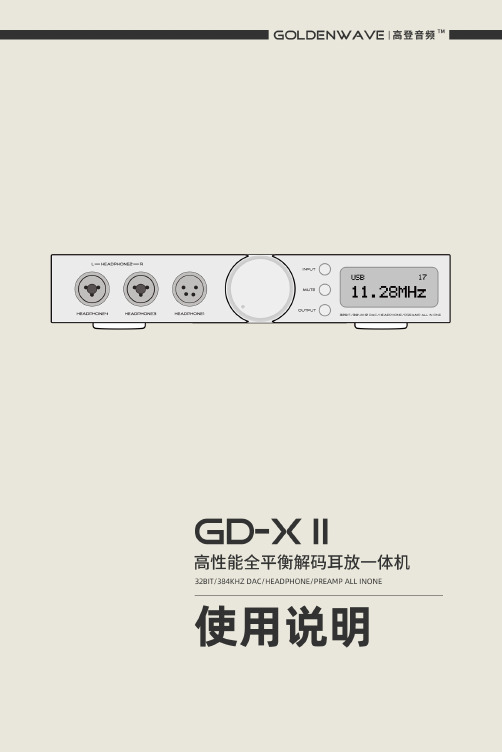
GD-X II使用手册说明书

9
PC 设置
(2) 待程序确认安装状态后,Next >( 下一步 ) 变为可点击状态,点击进 入下一步。如果有红色文字提示 Setup requires that the device is..., 请重开关 Sapphire III 或者重新拔插 USB 线。
连接设备 .................................................. 3 环境要求 ............................................... 4 连接数字音源 ........................................... 4 连接其他音频设备(充当前级放大器)...................... 4 连接电源 ............................................... 6 连接耳机 ............................................... 7
(3) 按提示点击 Next >( 下一步 ) 或者 Install( 安装 ) 即可。
10
PC 设置
(4) 安装过程大概需要 3 到 5 分钟。
(5) 若出现安装警告,点击“始终安装此驱动程序软件”。
11
PC 设置
(5) 安装成功时,界面会提示“Preinstallation was successful”, 即安装成功,再点击 Next>( 下一步 ) 退出即可。
附送的 USB 线缆
OTG 线缆
* 功能等同于 OTG 线缆,可在各大电商网站搜索“Lightning 至 USB 转换器”或者“iPhone OTG”等关键字购得
电气控制开关操作方法

电气控制开关操作方法
电气控制开关可以通过以下几种方法进行操作:
1. 手动操作:通过手动打开或关闭开关,可以直接控制电路的通断状态。
这种方法适用于简单的电气控制系统,如照明开关或手动切换控制器。
2. 自动操作:通过自动化设备,如传感器、计时器或程序控制器等,来控制开关的状态。
当自动控制设备检测到特定条件或触发事件时,会发送信号给开关,使其打开或关闭。
3. 远程操作:通过遥控器、无线网络或互联网等远程控制设备,可以实现对开关的远程操作。
用户可以通过手机、平板电脑或电脑等终端设备发送指令,远程控制开关的状态。
4. 压力操作:通过压力传感器控制开关的状态。
当传感器检测到特定的压力值时,会触发开关动作,实现电路的通断控制。
5. 温度操作:通过温度传感器控制开关的状态。
当传感器检测到设定的温度值时,会触发开关动作,实现电路的通断控制。
需要注意的是,在进行电气控制开关操作时,应根据具体的应用需求和安全要求选择适当的方法,并确保操作的准确性和可靠性。
在使用自动化设备或远程控制
时,还应确保设备的正常运行和网络的稳定性。
此外,应按照相关的电气安全规范和操作说明进行操作,以确保人员和设备的安全。
XGN2-12高压开关柜结构原理

XGN2-12高压开关柜结构原理由主母线室、小母线室、端子室、开关室、开关室包括(上隔离开关、下隔离开关、上接地刀闸、下接地刀闸、电流互感器、零序互感器、避雷器、真空断路器)、机械闭锁、微机保护装置、保护连片、电流表、信号灯、转换开关、高压带电显示器、程序锁、照明灯、柜体等组成。
工作原理:储能、合闸、分闸根据原理图可知在保证正常开启前应先检查隔离刀闸是否已经合上,控制电源开关已合上,操作转换把手应打在正常工作位置,远方、就地转换开关打在就地位置,储能已经就绪,储能、分闸指示灯亮,微机保护器上无任何异常显示。
储能工作原理合上储能空断,将储能开关打在合的位置,储能电机得电动作带动凸轮机构转动到一定位置使位置开关WK动作,其常闭触点断开使储能电机失电停止运转,同时常开触点闭合使储能指示灯亮储能结束,为开车作准备。
合闸(送电)原理按启动按钮或在开关柜上扳动分、合闸转换开关到合闸位置,合闸线圈HQ得电,线圈铁芯杆推动断路器机构动作,挂住机构,主回路接触器动触头动作,接触静触头给电机供电带动电机运转工作。
同时断路器辅助触点DL常闭触点断开使合闸线圈HQ断电,防止该线圈因长时间得电烧毁,线圈失电后线圈铁芯杆在弹簧力的反作用下返回原位;辅助触点DL常闭触点断开,使分闸指示灯熄灭;微机上分位指示灯熄灭。
分闸停车回路DL常开触点闭合为停车作准备,同时运行指示灯亮,微机上合位指示灯亮,此时启动完成。
(启动运行时电流表指针应有明显的指示,微机显示器上有电流显示,电机运行正常。
)分闸(停电)原理按停止按钮或在开关柜上扳动转换开关到分闸位置,分闸线圈TQ得电,分闸线圈铁芯杆推动断路器机构杆动作,断路器主触头分断断开,电机失电停止运行。
断路器辅助触点DL常开触点断开使分闸线圈TQ断电,防止线圈长期得电烧毁,线圈铁芯杆在弹簧力的反作用下恢复还原;合闸回路DL常闭触点闭合为下次开车作准备,同时运行指示灯、微机上的合位指示灯熄灭,分闸指示灯亮,停车结束。
施歌电气 XG2 系列发电机-主电源保护 使用手册说明书

GENERATOR-MAINS PROTECTIONOriginal documentEnglish Revision: DXG2PROTECTION TECHNOLOGY MADE SIMPLEGENERATOR-MAINS PROTECTIONProfessional LineSEG Electronics GmbH Manual XG2 SEG Electronics reserves the right to update any portion of this publication at any time.Information provided by SEG Electronics is believed to be correct and reliable.However, no responsibility is assumed by SEG Electronics unless otherwise expressly undertaken.© SEG Electronics 2022. All rights reserved.2 DOK-TD-XG2, Rev. DManual XG2 SEG Electronics GmbHContents1.Applications and features (4)2.Design (5)3.Function (7)4.Operation and settings (12)4.1Setting of DIP-switches (13)4.2Setting of tripping values (14)4.3Communication via serial interface adapter XRS1 (15)5.Relay case and technical data (16)5.1Relay case (16)5.2Technical Data (17)DOK-TD-XG2, Rev. D 3SEG Electronics GmbH Manual XG2 1. Applications and featuresVector surge relay XG2 of the PROFESSIONAL LINE pro-vides reliable protection for generators in parallel operation with the mains, by switching off very quickly in case of mains failure. Supervision of the phase sequence is also possible.When compared to conventional protection equipment all relays of the PROFESSIONAL LINE re-flect the superiority of digital protection techniques with the following features:•High measuring accuracy by digital data processing•Fault indication via LEDs•Extremely wide operating ranges of the supply volt-age by universal wide range power supply•Very fine graded wide setting ranges•Data exchange with process management system by serial interface adapter XRS1 which can be retrofitted•RMS measurement•Extremely short response time•Compact design due to SMD-technologyIn addition to this relay XG2 has the following special features:•Supervision of the phase sequence•Switching over from 1-phase measurement to 3-phase measurement4 DOK-TD-XG2, Rev. DManual XG2 SEG Electronics GmbH 2. DesignFigure 2.1: Connection two-wire systemFigure 2.2: Connection three--wire system ΔFigure 2.3: Connection four-wire system Y/ΔDOK-TD-XG2, Rev. D 5SEG Electronics GmbH Manual XG2 Analog inputsThe analog voltage input signals are connected to the protection device via terminals L1-L3 and N. Auxiliary voltage supplyUnit XG2 can be supplied directly from the measuring quantity itself or by a secured auxiliary sup-ply. Therefore a DC or AC voltage must be used.Unit XG2 has an integrated wide range power supply. Voltages in the range from 19 - 55 V DC can be applied at connection terminals A1 (L-) and A2 (L+). Terminals A1/A3 are to be used for voltag-es from 50 - 750 V DC or from 36 - 520 V AC.Contact positionsFigure 2.4: Contact positions of the output relays6 DOK-TD-XG2, Rev. DManual XG2 SEG Electronics GmbH 3. FunctionThe vector surge supervision protects synchronous generators in mains parallel operation due to very fast de-coupling in case of mains failure. Very dangerous are mains auto reclosing for syn-chronous generators. The mains voltage returning after 300 ms can hit the generator in asynchro-nous mode. The same very fast de-coupling is also necessary in case of transient mains failures. Generally there are two different applications:a) Only mains parallel operation no single operation. In this application the vector surge supervision protects the generator by tripping the generator circuit breaker in case of mains failure.b) Mains parallel operation and single operation. For this application the vector surge supervision trips the mains circuit breaker. Here it is insured that the gen.-set is not blocked when it is required as the emergency set.A very fast decoupling in case of mains failures for synchronous generators is known as very diffi-cult. Volt-age supervision units cannot be used because the synchronous alternator as well as the consumer impedance support the decreasing voltage.The voltage reaches the threshold of voltage supervision unit because of this reason after a couple of 100 msec. and therefore a safe detection of auto reclosing in the mains is not possible with sin-gle-voltage supervision units.Also frequency relays cannot be used, because even a fully overloaded generator decreases the speed after 100 msec. Current protection relays detects the fault, by existing short circuit currents. Power sensing relays can also detect but cannot avoid the decreasing change of power to short circuit power. A problem is also the failure tripping of this kind of devices when to suddenly loading the generator. Without any mentioned limitation, the XG2 described detects mains failures within 70 msec., because it was specially designed for such kind of applications, where the kind of fault requires a very fast decoupling from the mains.The total tripping time lies still under 170 msec. even, when the circuit breaker time and the relay time is added. Requirement for a tripping of the generator mains monitor is a change of power of more than 15 - 20 % nominal power. Slow changes of the system frequency, for example control-ling of the governor does not trip the relay.Short circuits in the mains can also trip the relay, be-cause a vector surge higher than the preset threshold can be detected. The value of the vector surge is de-pendent on the short circuit distance to the generator. This function offers the advantage for the utility that the mains short circuit capaci-ty and therefore the energy feeding the short circuit is limited.DOK-TD-XG2, Rev. D 7SEG Electronics GmbH Manual XG28 DOK-TD-XG2, Rev. DMeasuring principle of vector surgeWhen a synchronous alternator is loaded, the rotor displacement angle is build between the termi-nal voltage (mains voltage U1) and the synchronous electromotive force (Up). Therefore a voltage is difference ΔU is built between Up and U1 (fig. 3.1).Figure 3.1: Equivalent circuit of synchronous generator in parallel with the mainsFigure 3.2: Voltage vectors at mains parallel operationThe rotor displacement angle between stator and rotor is depending of the mechanical moving torque of the generator shaft. The mechanical shaft power is balanced with the electrical feeded mains power, and therefore the synchronous speed keeps constant (figure 3.2).Manual XG2 SEG Electronics GmbHDOK-TD-XG2, Rev. D 9Figure 3.3: Equivalent circuit at mains failureIn case of mains failure or auto reclosing the generator suddenly feeds a very high consumer load. The rotor displacement angle is decreased repeatedly and the voltage vector U1 change its direc-tion U1 (figure 3.3 and 3.4).Figure 3.4: Voltage vectors at mains failureSEG Electronics GmbH Manual XG2Figure 3.5: Voltage vector shiftAs shown in the time diagram the voltage jumps to another value and the phase position change. This procedure is named phase or vector surge.The XG2 are continuously measuring the cycles, starting each zero message up ward slope.The cycle time is internally compared to the quarz table reference time. In case of vector surge as shown in fig. 3.5, the zero message is delayed and the device trips instantaneously. The trip angle Δ and consequently the sensitivity of the vector surge detection is adjustable.Information for useAlthough the vector surge relay guarantees very fast and reliable detection of mains failures under nearly all operational conditions of mains parallel running alternators, the following borderline cases have to be considered accordingly:a) No or only insignificant change of power flow at the utility connection point when a mains failure occursThis can arise during peak lopping operation or in CHP stations (Combined Heat and Power) where the power flow between power station and the public grid may be very low. For detection of a vector surge at parallel running alternators, the load change must be at least 15 - 20 % of the rat-ed power. If the active load at the utility connection point is regulated to a minimal value and a high resistance mains failure occurs, then there are no vector surge nor power and frequency changes and the mains failure is not detected.This can only happen if the public grid is disconnected near the power station and so the alterna-tors are not additionally loaded by any consumers. At distant mains failures the synchronous alter-nators are abruptly loaded by remaining consumers which leads directly to a vector surge and so mains failure detection is guaranteed.If such a situation occurs the following has to be taken into account:In case of an undetected mains failure, i.e. with the mains coupling C.B. in operation, the vector surge relay reacts upon the first load change causing a vector surge and isolates the mains C.B.10 DOK-TD-XG2, Rev. DManual XG2 SEG Electronics GmbH For detecting high resistance mains failures a zero sequence relay with an adjustable time delay can be used. A time delay is needed to allow regulating ac-tions where the current may reach "ze-ro" at the utility connection point. At high resistance mains failures, the mains coupling C.B. is tripped by the zero sequence relay after the time delay.To prevent asynchronous switching on, an automatic restart by the public grid should be not possi-ble during this time delay.As a further measure the load regulation at the utility connection point should be such that an ac-tive energy of 5 % of the alternator rated power is always flowing.b) Short circuit type loading of the alternators at distant mains failuresAt any distant mains failure, the remaining consumers cause sudden short circuit type loading of the power station alternators. The vector surge relay detects the mains failure in about 70 ms and switches off the mains coupling C.B. The total switch off time is about 150 - 170 ms. If the alterna-tors are provided with an extremely fast short circuit protection e.g. able to detect di/dt, the alterna-tors might be switched off unselectively by the alternator C.B., which is not desireable because the power supply for the station is endangered and later on synchronized changeover to the mains is only possible after manual reset of the overcurrent protection.To avoid such a situation, the alternator C.B.s must have a delayed short circuit protection. The delay time must be long enough so that mains disconnection by the vector surge relay is guaran-teed.DOK-TD-XG2, Rev. D 11SEG Electronics GmbH Manual XG212 DOK-TD-XG2, Rev. D4. Operation and settingsAll operating elements needed for setting parameters are located on the front plate of the XG2 as well as all display elements. Because of this all adjustments of the unit can be made or changed without disconnecting the unit from the DIN-rail.Figure 4.1: Front plateFor adjustment of the unit the transparent cover has to be opened as illustrated. Do not use force! The transparent cover has two inserts for labels.Figure 4.2: How to open the transparent coverManual XG2 SEG Electronics GmbH LEDsLED "ON" is used for display of the readiness for operation (at applied auxiliary voltage Uv) and flashes at wrong phase sequence. LED Δ signals tripping of the vector surge function.Test push buttonThis push button is used to test tripping of the relay and when pressed for 5 s a check up of the hardware takes place. Both output relays are tripped and the tripping LED lights up.4.1 Setting of DIP-switchesThe DIP switch block on the front plate of unit XG2 is used for adjustment of the nominal values and setting of function parameters:Table 4.1: Function of DIP-switches* Only one of the DIP-switches 1 - 3 shall be in …ON“-position at the same time.Rated voltageThe required rated voltage (phase-to-phase voltage) can be set with the aid of DIP-switch 1 - 3 to 100, 110, 230 or 400 V AC. It has to be ensured that only one of the three DIP-switches is switched on.The following DIP-switch configurations for adjustment of the rated voltage are allowed:Figure 4.3: Adjustment of rated voltageRated voltage chosen too low does not cause destruction of the unit but leads to wrong measuring results which may lead to false tripping.Phase sequence supervisionIf DIP switches 4 and 5 are in position "ON", the phase sequence supervision is active. Wrong phase sequence is indicated with the flashing LED "ON" and all output relays will be tripped. A cor-rect phase sequence is indicated with the permanently lit LED "ON".The phase sequence supervision is activated when UB< is exceeded. When connected to two-wire systems, the phase sequence supervision must be switched off.DOK-TD-XG2, Rev. D 13SEG Electronics GmbH Manual XG214 DOK-TD-XG2, Rev. DSupervision of single- and three-phase AC voltagesFor supervision of single phase AC voltages DIP-switch 4 + 5 must be switched off. If three phases should be supervised, DIP switch 5 has to be in position "ON".For supervision of 3-wire systems without N the DIP switch 5 must be in position ON.Note!Single-phase supervision (DIP switch 5 = OFF) can also be switched on with three-phase connec-tion. The device triggers if in at least one of the three phases the set limit value Δ is exceeded and the surge in the remaining phases is not bigger than 1° in the opposite direction.The three-phase supervision (DIP switch 5 = ON) trips if in at least two of the three phases the set limit value is exceeded and the surge in the remaining phase is not bigger than 1° in the opposite direction. The vector surge supervision is only active when the blocking period of tv = 5 s has ex-pired and the phase voltages exceed the blocking voltage UB<.Thanks to the criterion of the angular surges in the opposite direction, unintented disconnection during transient balancing processes is prevented.4.2 Setting of tripping valuesThe PROFESSIONAL LINE units have the unique possibility of of high accuracy fine adjustments. For this, two potentiometers are used. The course setting potentiometer can be set in discrete steps of 5°. A second fine adjustment potentiometer is then used for setting of the final 1 - 6°. Adding of the two values results in the precise tripping value.Vector surge trippingBy using the potentiometer shown on the following figure, the vector surge trip relay can be adjust-ed in a range from 1° to 31° in 1° steps.Example:The requested tripping value to be set is 19°. To achieve this, the setting value of the potentiometer on the right is simply to be added to the value of the potentiometer on the left. (The arrow of the po-tentiometers must always be in the middle of the marked bar, otherwise a definite setting value is not possible).Figure 4.4: Adjusting exampleBlocking timeTo prevent wrong trippings caused by oscillations after the synchronizing procedure, tripping is blocked after applying the measuring voltage for a fixed time tv = 5 s.If the measuring voltage drops below U B < the blocking time tv is reset. tv is activated again if the measuring voltage exceeds UB<.Blocking voltageWith the aid of potentiometer U B </Un the blocking voltage can be set continuously variable in the range from 20 - 70 % Un (phase-to-phase voltage).Manual XG2 SEG Electronics GmbH 4.3 Communication via serial interface adapter XRS1Figure 4.5: Communication principleFor communication of the units among with a superior management system, the interface adapter XRS1 is available for data transmission, including operating software for our relays. This adapter can easily be retrofitted at the side of the relay. Screw terminals simplify its installation. Optical transmission of this adapter makes galvanic isolation of the relay possible. Aided by the software, actual measured values can be processed, relay parameters set and protection functions pro-grammed at the output relays. Information about unit XRS1 in detail can be taken from the descrip-tion of this unit.DOK-TD-XG2, Rev. D 15SEG Electronics GmbH Manual XG216 DOK-TD-XG2, Rev. D5. Relay case and technical data5.1 Relay caseRelay XG2 is designed to be fastened onto a DIN-rail acc. to DIN EN 50022, the same as all units of the PROFESSIONAL LINE.The front plate of the relay is protected with a sealable transparent cover (IP40).Figure 5.1: Dimensional drawingsConnection terminalsThe connection of up to a maximum of 2 x 2.5 mm 2 cross-section conductors is possible. For this the transparent cover of the unit has to be removed (see chapter 4).Manual XG2 SEG Electronics GmbH 5.2 Technical DataConnection possibilities:Table 5.1: Connection possibilitiesMeasuring input circuitsRated dataRated voltage Un: 100, 110, 230, 400 V AC (phase-to-phase voltage)Rated frequency range: 35 - 78 Hz (35 - 66 Hz at communication viaserial interface)Power consumptionat the voltage circuit: 1 VA/per phase at UnThermal carrying capacityof the voltage circuit: continuously 520 V ACAuxiliary voltageAuxiliary voltage range: 36 - 520 V AC(*) (f = 35 - 78 Hz)or 50 - 750 V DC(*) / 4 W (terminals A1-A3)(*) max. 300 V AC / 424 V DC against ground (earth). Power consumption: 19 - 55 V DC / 3 W (terminals A1 (L-) and A2 (L+))Common dataDropout to pickup ratio: depending on the adjusted hysteresisResetting time from pickup: <50 msReturning time from trip: 500 msMinimum initialization timeafter supply voltage has applied: 100 msMinimum response timewhen supply voltage is available: 70 msOutput relayNumber of relays: 2Contacts: 1 changeover contact for each trip relayMaximum breaking capacity: ohmic 1250 VA/AC or 120 W/DCinductive 500 VA/AC or 75 W/DCMax. rated voltage: 250 V AC220 V DC ohmic load Imax. = 0,2 Ainductive load Imax. = 0,1 A at L/R ≤ 50 ms24 V DC inductive load Imax. = 5 AMinimum load: 1 W / 1 VA at Umin ≥ 10 VMax. rated current: 5 AMaking current (16 ms): 20 AContact life span: 105 operations at max. breaking capacityDOK-TD-XG2, Rev. D 17SEG Electronics GmbH Manual XG2 System dataDesign standards: VDE 0435, VDE 0843 Part 1-4, VDE 0871, EN 50178:1998 Temperature rangeat storage and operation: -25°C to +70°CClimatic resistance class Facc. to DIN 40040 andDIN IEC 68, T.2-3: more than 56 days at 40°C and 95 % relative humidity High voltage test acc. to VDE 0435, part 303Voltage test: 2.5 kV (eff.), 50 Hz - 1 minSurge voltage test: 5 kV, 1.25/50 µs, 0.5 JHigh frequency test: 2.5 kV/1MHzElectrostatic discharge (ESD)acc. to IEC 0801 part 2: 8 kVRadiated electro-magnetic fieldtest acc. to IEC 0801 part 3: 10 V/mElectrical fast transient (burst)acc. to IEC 0801 part 4: 4 kV / 2.5 kHz, 15 msRadio interference suppressiontest acc. to DIN 57871and VDE 0871: limit value class ARepeat accuracy: 0.2°Rated values: 0.4°Frequency effect: 0.2° for the whole frequency rangeMechanical testShock: class 1 acc. to DIN IEC 255-21-2Vibration: class 1 acc. to DIN IEC 255-21-1Degree of protectionFront plate: IP40 when the front cover is closedWeight: approx. 0.5 kgMounting position: anyRelay case material: self-extinguishingTable 5.2: Setting ranges and graduationTechnical data subject to change without notice!18 DOK-TD-XG2, Rev. DManual XG2 SEG Electronics GmbH Setting-list XG2Project: Job.-no.:Function group: = Location: + Relay code: -Relay functions: Date:Setting of parameters*Only one of the DIP-switches 1 - 3 shall be in …ON“-position at the same time.DOK-TD-XG2, Rev. D 19Professional Linehttps://docs.SEGelectronics.de/xg2SEG Electronics GmbH reserves the right to update any portion of this publication at any time.Information provided by SEG Electronics GmbH is believed to be correct and reliable. However, SEGElectronics GmbH assumes no responsibility unless otherwise expressly undertaken.SEG Electronics GmbHKrefelder Weg 47 ∙ D–47906 Kempen (Germany)Postfach 10 07 55 (P.O.Box) ∙ D–47884 Kempen (Germany)T elephone: +49 (0) 21 52 145 1Internet: www.SEGelectronics.deSalesT elephone: +49 (0) 21 52 145 331Fax: +49 (0) 21 52 145 354E-mail: **********************ServiceT elephone: +49 (0) 21 52 145 600Fax: +49 (0) 21 52 145 354E-mail: **********************SEG Electronics has company-owned plants, subsidiaries, and branches, as well as authorized distributors and other authorized service and sales facilitiesthroughout the world.Complete address / phone / fax / email information for all locations isavailable on our website.MANUAL │ XG2XG2。
XGN2高压柜工作原理

变压器日常巡视检查应包括以下内容:
XGN高压柜常见故障分析
8、开关储能后自动合闸的原因: ①开关柜上手动合闸按钮未复原顶住合闸 机构杆; ②合闸线圈铁芯杆得电动作后卡住合闸机 构,不能退回; ③启动按钮卡住不能复原; ④启动按钮控制线短路。
隔离开关接触部分发热的原因有哪 些?如何处理?
引起隔离开关接触部分发热的原因有: (1)压紧弹簧或螺丝松劲; (2)接触面氧化,使接触电阻增大; (3)刀片与静触头接触面积太小,或过负荷运行; (4)在拉合过程中,电弧烧伤触头或用力不当,使接触 位置不正,引起压力降低。 处理方法有: (1)检查、调整弹簧压力或更换弹簧。 (2)用“0-0”号砂纸清除触头表面氧化层,打磨接触面, 增大接触面,并涂上中性凡士林。 (3)降负荷使用,或更换容量较大的隔离开关。 (4)操作时,用力适当,操作后应仔细检查触头接触情 况。
故障和机械故障两类。 电气故障可分为电动不能储能、电动 不能合闸、电动不能分闸等。 机械故障主要有:机械连锁故障、操作 机构故障等。故障部位多是紧固部位 松动、传动部件磨损、限位调整不当 等。
1、按合闸按钮开关不动作 ①看有无电源; ②空断是否合上; ③是否已储能; ④储能后微动开关触点是否接触完好; ⑤启动按钮是否完好 ,分闸指示灯应亮; ⑥以上无异则查看启动按钮处有无220V直电压; ⑦无则检查合闸回路的线圈、常闭触点是否完好正常; ⑧远方就地开关是否打在就地位置; ⑨北京高开的应打开面板检查控制插件是否振松。
XGN2-12(Z)固定式高压开关柜的结构与参数及操作程序

XGN2-12(Z)固定式高压开关柜结构与参数及操作程序XGN2-12(Z)固定式高压开关柜,简称开关柜;图3-4外形图。
适用于3~10kV三相交流50Hz系统中作为接受与分配电能之用,并具有对电路进行控制、保护和检测等功能。
特别适用于频繁操作的场所,其母线系统为单母线,并可派生出单母线带旁路和双母线结构。
经过多年的改进完善,产品最大额定电流可做到4000A;可在海拔4000m以下正常运行。
本开关柜既可采用ZN28A-12分体式真空断路器,还可配用ZN28D-12、VS1-12、ZN12-12、ZN65-12等整体式真空断路器;隔离开关主要采用旋转式GN30-12(D),大电流柜也可采用GN25-12,GN22-12等隔离开关。
由于该产品电流等级大,母线结构多样,所以在变电站得到广泛应用。
1.产品型号含义:3.隔离开关:GN30-12(D)型的基本参数,表3-4:4.开关柜外形尺寸:*小电流柜电缆进出线及联络柜标准方案: 宽1100×深1200×高2650。
*小电流架空进出线柜标准方案: 宽1100×深(1200+400)×高2650。
*大电流柜电缆进出线及联络柜标准方案: 宽1200×深1200×高2650。
*大电流架空进出线柜标准方案: 宽1200×深(1200+600)×高2650。
注: 小电流柜的相间距为250mm; 大电流柜的相间距为275mm;5.开关柜的结构:图3-4为外型图,图3-5为配ZN28A-12真空断路器的方案,图3-6为配VS1真空断路器的方案。
本开关柜为金属封闭箱型结构,柜体骨架由型钢和优质冷轧钢板焊接而成,柜内分为断路器室、主母线室、电缆室、继电器室,室与室之间用钢板隔开。
断路器室在柜体下部,ZN28A-12真空断路器的传动拉杆与操动机构连接,真空断路器下接线端子与电流互感器连接,电流互感器与下隔离开关的接线端子连接,真空断路器上接线端子与上隔离开关的接线端子连接。
水电站电气二次设备的安装与调试分析

水电站电气二次设备的安装与调试分析水电站电气二次设备的安装与调试是水电站建设中非常重要的环节,它直接关系到水电站的运行效率和安全稳定。
下面将对水电站电气二次设备的安装与调试进行分析。
水电站电气二次设备的安装要注意以下几个方面:设备的摆放位置、接线端子的正确连接、设备的固定和接地等。
在选择摆放位置时,首先要考虑设备的通风散热和维修保养的便利性,避免设备相互干扰导致故障。
设备的接线端子必须按照设计要求进行接线,不能出现错误连接,避免因接错导致设备无法正常工作或引发事故。
设备的固定和接地也是非常重要的,只有设备固定稳定和良好接地,才能保证设备的安全运行。
水电站电气二次设备的调试也是一个至关重要的过程。
调试主要包括参数设置、设备启动和测试等步骤。
参数设置是根据设计要求对设备进行合理的参数设置,如调整保护装置的动作时间、电流互感器的等级等。
这些参数设置直接关系到设备的正常运行和安全性能。
设备的启动是指根据操作规程,依次对设备进行开关操作,以保证设备的按序启动和互锁。
测试是对设备进行各项性能指标的检验,包括设备的运行状态、保护装置的动作逻辑和测试数据等。
只有经过全面的测试,设备的安全性、可靠性和稳定性才能得到保障。
为了保证水电站电气二次设备的安装与调试工作的顺利进行,需要注意以下几个关键点。
要严格按照相关标准和规范进行施工和设备选择,确保设备的质量和性能达到要求。
要加强施工过程中的质量控制,认真按照施工方案和图纸要求进行操作,避免疏忽和失误。
对安装和调试人员要进行专业培训,提高其技术水平和操作能力。
要建立健全相关的记录和档案,方便后期维护和管理。
水电站电气二次设备的安装与调试是一个关键且复杂的过程,需要严格按照相关要求进行操作,确保设备的安全可靠运行。
只有做好安装与调试工作,水电站才能发挥其正常的发电功能,保障水电站的经济效益和设备的寿命。
防电源接反,这里有个方法,加个肖特基二级管就可以!

防电源接反,这里有个方法,加个肖特基二级管就可以!熟悉二极管的特性就知道,二极管显著的一个特性就是单向导电性。
防止电路板正负极接反,在电路板中加二极管是最简单有效的方法。
为什么用肖特基二极管呢?因为肖特基二极管功耗低、超高速。
其最显著特点是反向恢复时间极短(可以小到几纳秒),正向导通压降0.4V左右。
其主要用于高频、低压、大电流整流二极管、续流二极管、保护二极管,也有在微波通信等电路中作整流二极管、小信号检波二极管使用。
在变频器、通信电源等应用中比较常见。
那么该怎么在电路板中加肖特基二极管呢?有几种方法:(1)最常见的就是在电路板电源输入正极上加一个二极管如图所示,在电源的正极上接个二极管,由二极管的单向导电性可知,此时,电源与负载电路板形成一条回路,电路板可正常工作。
当电源正负极接反时,如图所示:此时电流从电路板负极流向正极,经过二极管处时,由于二极管的单向导电性,阻止了电流流过,此时的电路板与电源无法构成一条回路,因此电源接反对电路板没有任何影响。
假如没有这个防电源接反二极管,当电源接反时,此时负载电路构成回路,负载流过的电流与正常情况不一样,从而导致负载电路烧毁。
(2)在电路板电源输入负极上加一个二极管原理和加在正极一样,当电源接反时,二极管阻止了电流流过,无法形成回路。
(3)一种无极电路接法上面单二极管防反接原理,只有当电源正负极接线正常时电路板才能正常工作。
下面介绍一种方法:电源正负极接反一样可以正常工作的电路原理。
具体原理如图所示。
(1)当输入IN1为正,IN2为负时,D1导通,D3截止,正电压电流从D1流向电路板正极;D4导通,D2截止,电路板负极电流由D4流向IN2,形成一条完整的回路,电路板正常工作。
(2)当输入IN2为正,IN1为负时,D2导通,D4截止,正电压电流从D2流向电路板正极;D3导通,D1截止,电路板负极电流由D3流向IN1,形成一条完整的回路,电路板正常工作。
总结:此电路的优点是,无论电源的正负极如何接线,电路板一样正常工作;缺点是,整个回路有两个二极管的压降。
开关柜二次控制原理与接线讲解学习

开关柜二次控制原理与接线讲解学习开关柜是指用于分配和控制电能的设备,常见于电力系统中。
开关柜的二次控制是指其中的“二次”信号传输和控制原理。
一、二次控制原理:开关柜的二次控制主要是通过信号传输和处理方式来实现。
常见的二次控制原理有以下几种:1.电位器调节型二次控制:通过调节电位器的阻值,来改变电路的工作参数,从而实现控制目的。
2.电压比例控制型二次控制:通过将测量得到的模拟电压信号与参考电压进行比较,从而控制电路的工作状态。
3.开关量控制型二次控制:通过将测量得到的模拟信号经过比较、判断、处理等操作,最终转换为开关量信号进行控制。
4.数模转换型二次控制:将模拟信号转换为数字信号,再通过数字信号的处理实现控制。
以上几种二次控制原理可以单独使用,也可以相互组合使用,根据实际控制需求进行选择。
二、二次控制接线讲解:开关柜的二次控制接线分为信号输入端和信号输出端,下面分别进行讲解:1.信号输入端接线:信号输入端主要接收来自传感器、测量设备等的信号,并对其进行采集和处理。
在接线时,需要根据信号类型选择相应的接线方式,如电位器调节型需要接入电位器,电压比例控制型需要接入模拟电压信号线,开关量控制型需要接入开关量信号线等。
2.信号输出端接线:信号输出端主要传输处理好的信号,并控制相应的设备工作。
在接线时,需要根据设备类型和控制方式选择相应的接线方式,如控制电机需要接入电机控制线圈,控制继电器需要接入继电器控制线圈等。
3.接线注意事项:在进行二次控制接线时,需要注意以下几点:(1)接线可靠性:接线时要确保接触良好,不得出现接触不良、插拔不良等情况。
(2)接线规范:按照设计规范和相关标准进行接线,确保接线正确、安全。
(3)接线保护:合理布置电缆线路,进行绝缘保护,避免电缆磨损、短路等情况。
(4)接线标识:在接线时要进行标识,方便维护和排查故障。
电气二次控制回路基础知识精讲(通俗易懂),萌新都能看懂!

电气二次控制回路基础知识精讲(通俗易懂),萌新都能看懂!电气二次原理接线图是用来表示二次接线各元件(仪表、继电器、信号装置、自动装置及控制开关等设备)的电气联系及工作原理的电气回路图。
那么电气二次控制回路图怎么看呢?首先,我们来先认识一些低压元器件。
(1)低压电器简介1. 刀闸开关控制对象:380V, 5.5kW 以下小电机2. 熔断器作用:用于短路保护。
3. 控制按钮4. 行程开关5. 接触器6. 热继电器功能:过载保护(2)基本控制环节1. 异步机的直接起动1)点动控制2)电动机连续运行3)多地点控制4)点动+连续运行2. 电机的正反转控制3. 电机的正反转控制—加互锁4. 行程控制5. 定时控制空气式时间继电器的工作原理:6. 时间继电器触头类型7. 定时控制例一:电机的Y-△起动8. Y-△ 起动控制电路9. 定时控制例二:顺序控制1)顺序控制电路:两电机只保证起动的先后顺序,没有延时要求。
2)顺序控制电路:M1起动后,M2延时起动。
(3)电动机的保护1. 失压保护2. 短路保护方法:加熔断器。
异步电动机的起动电流( Is t)约为额定电流(IN)的 (5~7)倍。
选择熔体额定电流时,必须躲开起动电流,但对短路电流仍能起保护作用。
通常用以下关系:3. 过载保护方法:加热继电器。
4. 自动空气断路器(自动开关)作用:可实现短路、过载、失压保护。
(4)控制电路读图和设计中应注意的问题1. 首先了解工艺过程及控制要求;2. 搞清控制系统中各电机、电器的作用以及它们的控制关系;3. 主电路、控制电路分开阅读或设计;4. 控制电路中,根据控制要求按自上而下、自左而右的顺序进行读图或设计;5. 同一个电器的所有线圈、触头不论在什么位置都叫相同的名字;6. 原理图上所有电器,必须按国家统一符号标注,且均按未通电状态表示;7. 继电器、接触器的线圈只能并联,不能串联;8. 控制顺序只能由控制电路实现,不能由主电路实现。
XG2822电路

由XG2822构成的耳聋助听器电路
图(a)是由功放XG2822构成的的耳聋助听器电路。
适用于耳聋程度不同的患者。
1.电路组成
图(a)所示电路是由双功放集成电路XG2822(IC1)为主构成的。
MIC为驻极话筒;RP1用于调节MIC的接收灵敏程度;XS为耳机插座,兼作电源开关,与8Ω的低阻耳塞插头配合使用;RP2为音量调节电位器;IC1是一块内含两组独立音频功率放大器的IC,其内电路方框图如图(b)所示。
2.工作原理
(1)信号流程
语音信号被MIC话筒接收转换为电信号后经C1耦合加到IC1-1⑥脚,经放大后从③脚输出,再经C3耦合,R2与R3分压,RP2调节以后加到IC1-2⑦脚,由该电路进一步放大以后从①输出,由C9电容耦合,经XS插座②脚去驱动耳机发声。
(2)元件作用
调节RP2可改变耳机中音量的大小;电容C5、C6为高频滤波网络,用于防止电路产生自激;电阻R4与电容C8为茹欠尔网络,用于抑制高频滤波网络,以提高音频信号的纯度。
C2、C7均为交流负反馈电容。
(3)电源开关
电源开关是利用XS插座上的触点断开与接通来实现的。
当将耳塞插入XS内时,XS 插座的①与③触点闭合,即可接通电源负极与电路地线,使电路得电工作。
水电站电气二次设备的安装与调试分析

水电站电气二次设备的安装与调试分析水电站电气二次设备是指用于水电站发电机组运行和输电线路过载保护、自动化控制、测量、监控等用途的设备。
其安装与调试是确保水电站运行安全稳定、提高发电效率的重要环节。
本文将从安装与调试步骤、常见问题及解决方法等方面展开分析。
一、安装步骤1. 安装前的准备工作在进行电气二次设备安装之前,首先需要对设备进行检查,确保设备完好无损,同时对安装现场进行环境检查,确保安装条件符合要求。
需要准备好相应的安装工具和材料,以确保安装顺利进行。
2. 设备安装在进行设备安装时,需要严格按照设备安装说明书和相关标准进行操作,确保设备安装牢固、连接可靠。
同时还需对设备进行线路接地、屏蔽等工作,以确保设备的安全可靠性。
3. 设备连接及接线在设备安装完成后,需要进行设备之间的连接及接线工作。
这一步需要精心操作,确保连接可靠、接线正确,避免因接线错误导致设备故障或运行不稳定。
4. 设备调试前的检查在进行设备调试之前,需要对已安装设备进行全面检查,确保设备安装符合要求,连接正确可靠,无漏电、短路等问题存在。
二、调试分析1. 设备调试及功能测试调试工作主要包括设备参数的设置、功能测试及联锁试验等工作。
在进行设备调试时,需要根据设备的说明书进行参数设置,同时进行相应的功能测试,确保设备各项功能正常。
2. 故障排除在设备调试过程中,有可能会出现各种故障,如设备无法通电、功能异常、参数设置错误等。
在遇到这些问题时,需要及时进行故障排除,找出故障原因并进行修复。
3. 调试完成及验收在设备调试工作完成后,需要进行设备的整体检测及验收工作。
这一步是确保设备调试工作的关键环节,只有通过了整体检测及验收工作,设备才能正式投入运行。
三、常见问题及解决方法1. 设备无法通电可能原因:电源接线错误、设备损坏等。
解决方法:检查电源接线是否正确,排除电源故障;如电源正常,检查设备是否损坏,如发现损坏部分及时更换。
2. 设备功能异常可能原因:参数设置错误、接线不良等。
机床电气控制线路操作方法

机床电气控制线路操作方法
机床电气控制线路操作方法通常分为以下几个步骤:
1. 了解机床电气控制线路的原理和结构:熟悉机床电气控制线路的组成部分,例如电气控制柜、开关按钮、电动机等,以及线路的连接关系。
2. 做好安全措施:在进行任何电气控制线路操作之前,确保自身安全,例如戴好绝缘手套、工作服,仔细检查线路是否带电。
3. 打开电源:将电源开关打开,通电。
4. 操作开关按钮:根据需要,按下或拨动相应的开关按钮,例如启动按钮、停止按钮、正反转按钮等,来实现机床的运行、停止以及方向的控制。
5. 调节速度和位置:如果需要调节机床的运行速度和位置,可以通过旋转或拨动相应调速和调位开关按钮来实现。
6. 关闭电源:操作完毕后,将电源开关关闭,断电。
需要注意的是,在进行机床电气控制线路操作时,必须严格按照相关操作规程和注意事项进行,以确保操作的安全和正确性。
如果不熟悉电气控制线路的操作方
法,最好请专业的技术人员进行操作或指导。
开关柜二次控制原理与接线

开关柜二次控制原理与接线一、开关柜二次控制原理开关柜的二次控制是指使用开关柜上的辅助电路和接线进行信号传输和控制执行器的操作。
开关柜的辅助电路主要用于控制电磁继电器、断路器和接触器等开关元件,实现电气设备的远程操作和监控。
1.开关量控制:通过输入的高低电平信号(0V或24V)控制开关元件的断开和闭合。
例如,当输入信号为高电平时,柜内的继电器闭合,从而使得控制回路完成闭合,实现设备的工作。
2.模拟量控制:通过电流或电压的连续变化控制开关元件、执行器或调整器的位置、速度、温度等。
模拟量控制可以实现设备的精确控制和调节。
3.逻辑控制:通过逻辑运算进行开关元件的切换和组合,实现复杂的控制逻辑。
逻辑控制可以利用逻辑门或PLC等进行逻辑判断和控制操作。
二、开关柜二次控制接线1.并联控制接线:多个控制按钮并联接入继电器或接触器的控制回路,通过任意一个按钮的闭合都可以控制开关元件的动作。
这种接线方式适用于需要多个位置控制的场合,如远程和本地控制。
2.串联控制接线:多个控制按钮串联接入继电器或接触器的控制回路,只有同时按下所有按钮才能控制开关元件的动作。
这种接线方式适用于需要多重保护的设备,如按钮必须同时按下才能启动。
3.平行控制接线:多路控制信号平行接入继电器或接触器的控制回路,每个信号独立控制一个开关元件。
这种接线方式适用于需要分别控制多个开关元件的场合,如分别控制多个电动机的起停。
4.反馈控制接线:开关元件动作后,通过传感器或反馈信号将动作状态反馈给控制回路,以实现闭环控制。
例如,通过电流互感器将电机运行状态反馈给PLC控制系统,实现过载保护和远程监控。
以上只是一些常见的开关柜二次控制接线方式,实际应用中还可以根据具体需要进行自由组合。
在接线时应注意合理安排电缆的布线和保护措施,确保接线的可靠性和安全性。
同时,在接线之前需要进行电路的调试和测试,确保控制系统的正常工作。
两级常开触点开关使用方式

两级常开触点开关使用方式
两级常开触点开关是一种常见的电路控制器,通常用于开关电气设备的电路。
其原理是通过触点的通断控制电流的通断,从而实现电路的开关控制。
下面详细介绍其使用方式。
1. 贴片型两级常开触点开关的使用方式
首先,需要确定开关的输入和输出端口。
输入端口通常是开关的中央引脚,输出端口则是开关的两侧引脚。
接下来,将输入端口连接到电路的电源端,输出端口连接到需要控制的负载端。
以控制LED灯为例,连接方式如下:
将开关的中央引脚连接到电源的正极,将开关的两侧引脚连接到LED的正极和电源的负极,这样当开关打开时,电流就可以从电源流经LED并返回电源,从而点亮LED;当开关关闭时,电路断开,LED 熄灭。
2. 立式两级常开触点开关的使用方式
立式两级常开触点开关的使用方式与贴片型类似,只是连接方式略有不同。
首先,需要将开关拆开,将两个触点分别连接到需要控制的电路中。
以控制电机为例,连接方式如下:
将开关的一个触点连接到电机的正极,另一个触点连接到电源的正极,这样当开关打开时,电流就可以从电源流经开关和电机,并返回电源,从而驱动电机旋转;当开关关闭时,电路断开,电机停止运转。
总之,两级常开触点开关的使用方式和连接方式可能会因不同的负载和电路而有所变化。
在使用时,需要仔细阅读开关的使用说明书,并根据具体情况进行连接。
电力二次设备调试步骤

二次设备调试步骤二次设备调试步骤如下:1、接线:连接远动机、后台服务器、公共测控和一切电气设备上测控装置的网线。
2、对点:效验电气设备上面的各个辅助节点是否一一对应。
在电气设备上面操作看后台是否对应。
3、测控装置保护试验:用继电保护测试仪给保护装置加上电压和电流,看看保护是否能正确动作,主要看速断和过流保护。
4、单体调试:对单个设备(开关)进行分合闸、保护跳闸试验。
5、联调:对多个设备(开关)进行分合闸和连跳试验,目的是看看保护逻辑是否正确。
6、保护定值:由调度或者电力公司计算出各个电气设备的定值,然后输入到保护装置里面。
7、和调度对点:与调度核对遥测和遥信的点。
8、调试完成。
我们常听说的四遥功能由远动系统终端RTU实现,它包括:遥测(遥测信息):远程测量。
采集并传送运行参数,包括各种电气量(线路上的电压、电流、功率等量值)和负荷潮流等。
遥信(遥信信息):远程信号。
采集并传送各种保护和开关量信息。
遥控(遥控信息):远程控制。
接受并执行遥控命令,主要是分合闸,对远程的一些开关控制设备进行远程控制。
遥调(遥调信息):远程调节。
接受并执行遥调命令,对远程的控制量设备进行远程调试,如调节发电机输出功率。
一遥:指遥信功能。
两遥:指遥信和遥测功能。
三遥:指实现遥信、遥测和遥控功能。
四遥:指实现遥信、遥测、遥控和遥调功能。
具备遥控、遥测、遥信、遥调功能的系统。
又称遥控遥测遥信遥调系统。
四遥系统主要用于输油输气管线等分散目标型系统。
中国已研制成通用分散目标型四遥设备。
四遥功能即遥信(YX),遥测(YC),遥控(YK)和遥脉(YM)。
遥信:要求采用无源接点方式即某一路遥信量的输入应是一对继电器的触点,或者是闭合,或者是断开。
通过遥信端子板将继电器触点的闭合或断开转换成为低电平或高电平信号送入RTU的YX模块。
遥信功能通常用于测量下列信号,开关的位置信号、变压器内部故障综合信号、保护装置的动作信号、通信设备运行状况信号、调压变压器抽头位置信号。
XGN2B开关柜培训教程

XGN2B开关柜的结构及原理
• 5、防误机械联锁装置 • 五防闭锁功能是通过装配于开关柜上 的防误机械联锁装置来实现的。且以 闭锁功能手柄处在“检修”、“工 作”、“分断闭锁”三个不同的位置 来限制进行各种操作。 • (1)闭锁功能手柄处在“检修”、 “工作”、“分断闭锁”三个不同的 位置时的作用: • a 、在“分断闭锁”位置时,不能分 合开关(由于限位机构闭锁,一但合 上立即自动跳开),开关柜门处于关 闭状态,只能操作刀闸和地刀,这是 为了防止运行时带负荷合刀闸。
ZN98-12型真空断路器面板图(正面)
ZN98真空断路器的结构、使用要求及原理
• • • • • • • • • • 2.触头压力弹簧 3.弹簧座 4.接触行程调整螺栓 5.拐臂 6.导向板 7.螺钉 8.导电夹紧固螺栓 9.下支座 10.真空灭弧室 11.真空灭弧室 12.上支座 13.绝缘子固定螺丝 14.绝缘子 15.螺栓 16.连接弹簧或电磁操动机构的 大轴
•
XGN2B开关柜的结构及原理
• d、当断路器分闸后,闭锁功能手柄才能从“工作”位置转到“分断闭锁”位 置,进行隔离开关和接地刀闸的操作,;当隔离开关分闸,接地刀闸合闸后, 闭锁功能手柄才能从“分断闭锁”位置转到“检修”位置,功能手柄只有在 “检修”位置柜门才能打开,反之,只有当柜门关闭后,闭锁功能手柄才能 从“检修”位置转到“分断闭锁”或“工作”位置,当柜门处于打开位置时, 闭锁功能手柄始终处于“检修”位置,防止误送电到检修间隔。 (3)设备的操作顺序: a、停电检修的操作: 断开断路器――把手拔至“分断闭锁”――分下隔离――分上隔离――合接 地刀――把手拔至“检修”位置――开前门――拿钥匙去开后门。 b、送电操作: 关后门――拿后门的钥匙插在前门上,关前门――把手拔至“分断闭 锁”――分接地刀――合上隔离――合下隔离――把手拔至“工作”位置 ――合断路器。 前门和后门要用钥匙来实现闭锁。这样做,目的是为了预防检修完毕,在没 有关好后门的情况下,进行送电操作,防止误入带电间隔。
- 1、下载文档前请自行甄别文档内容的完整性,平台不提供额外的编辑、内容补充、找答案等附加服务。
- 2、"仅部分预览"的文档,不可在线预览部分如存在完整性等问题,可反馈申请退款(可完整预览的文档不适用该条件!)。
- 3、如文档侵犯您的权益,请联系客服反馈,我们会尽快为您处理(人工客服工作时间:9:00-18:30)。
导线
电池
下一步
导线
电池
返回
灯泡
电池
返回
灯泡
导线
返回
开
关
下一步
返回
返回
我们的声明:
• 同学要记清,发言仔细听。 • 实验轻声做,科学动脑筋。 • 记录要真实,合作很要紧。 • 材料保管好,我们最文明。
单键开关
拔动开关
三联开关
拉线开关
按钮开关 触 摸 屏 开 关
旋钮开关
两联开关
转换开关 按 钮 开 关 手电开关
矿 用 防 爆 开 关
空气开关是一种只要电路中电流过大 就会自动断开的开关。它利用了空气来 控制电路,达到保护的目的。
光控开关是一种利用光的强弱,从而 控制电路通断的开关。广泛应用于公共场 合起到日熄夜亮的控制作用,以节约用 电。
声控开关是一种利用声音的大小,从 而控制电路通断的开关。也适合用在公共 场合,可以根据人的活动自动开关,方便 实惠。
友情提示:
• • • • 请遵守《我们的声明》。 请保持周围环境的干净整洁。 别忘了把《记录表》交上来。 有什么问题,请轻轻地告诉老师或者 同学。
爱迪生,美国伟大的发明家, 他和他领导的研究所的发明超过 2000种。 爱迪生发明了电灯。为了研 制电灯,他搜集记录资料就用了 200多个笔记本,为了寻找制作灯 丝的材料,他做了1600多次耐热 材料和600多种植物纤维的实验, 最后选中了一种竹丝,经碳化才 制成最初的灯丝,制造出第一个 灯泡。因此,爱迪生常常说: “天才是百分之一的灵感加上百 分之九十九的勤奋。”
