用LM137电源设计
三端电源及LDO线性电源测试原理
三端稳压电源及LDO线性电源测试方法作者:李雷一、 器件介绍三端稳压器电路(简称三端电源)是模拟集成电路中较大的一个系列,也是各种电子系统中不可缺少的电源供电电路,它广泛的应用于各种电子整机和电源系统之中。
随着集成电路技术的快速发展,许多电源芯片公司推出了Low Dropout Regulator,即:低压差线形稳压器,简称LDO。
这种电源芯片的压差只有1.3-0.2伏,可以实现5v转3.3v/2.5v,3.3v转2.5v/1.8v等要求。
本文主要介绍通用线性电源的测试原理和实用测试方法。
1.三端稳压电源的分类从不同的角度,三端电源可以分为多类:1.从输入、输出电压极性上可分为:正稳压电源(如:78XX、78MXX、78LXX),负稳压电源(如:79XX、79MXX、79LXX)。
2.从输出电压幅度上可分为:5V输出----24V输出。
(如:7805,7809、7815、7824、7905、7909、7912、7915等)3.从输出功率上可分为:小功率L系列(IO=100MA)如:78L05、79L12等。
中功率M系列(IO=500MA)如:78M09、79M05等大功率系列(IO=1.5A)如:7812、7915等4.从封装形式上可分为:TO-3、TO-220、TO-39等。
5.从输出形式上可分为:固定输出(78XX、79XX、78MXX、79MXX等),可调输出(LM117/217/317、LM137/237/337、LM150、LM138等)。
6.从产品等级上可分为:军用级(LM117、LM137),工业级(LM217、LM237),民用级(LM317、LM337)。
2.三端电源的典型测试系统简介A LTX公司的SAI600测试包作为模拟器件测试系统著名生产厂家之一的LTX公司采用SAI600测试包对线性三端稳压器件进行测试。
SAI600测试包是基于大规模线性集成电路测试系统LTX-77 的一个通用测试包。
三端电源及LDO线性电源测试原理

三端稳压电源及LDO线性电源测试方法作者:李雷一、 器件介绍三端稳压器电路(简称三端电源)是模拟集成电路中较大的一个系列,也是各种电子系统中不可缺少的电源供电电路,它广泛的应用于各种电子整机和电源系统之中。
随着集成电路技术的快速发展,许多电源芯片公司推出了Low Dropout Regulator,即:低压差线形稳压器,简称LDO。
这种电源芯片的压差只有1.3-0.2伏,可以实现5v转3.3v/2.5v,3.3v转2.5v/1.8v等要求。
本文主要介绍通用线性电源的测试原理和实用测试方法。
1.三端稳压电源的分类从不同的角度,三端电源可以分为多类:1.从输入、输出电压极性上可分为:正稳压电源(如:78XX、78MXX、78LXX),负稳压电源(如:79XX、79MXX、79LXX)。
2.从输出电压幅度上可分为:5V输出----24V输出。
(如:7805,7809、7815、7824、7905、7909、7912、7915等)3.从输出功率上可分为:小功率L系列(IO=100MA)如:78L05、79L12等。
中功率M系列(IO=500MA)如:78M09、79M05等大功率系列(IO=1.5A)如:7812、7915等4.从封装形式上可分为:TO-3、TO-220、TO-39等。
5.从输出形式上可分为:固定输出(78XX、79XX、78MXX、79MXX等),可调输出(LM117/217/317、LM137/237/337、LM150、LM138等)。
6.从产品等级上可分为:军用级(LM117、LM137),工业级(LM217、LM237),民用级(LM317、LM337)。
2.三端电源的典型测试系统简介A LTX公司的SAI600测试包作为模拟器件测试系统著名生产厂家之一的LTX公司采用SAI600测试包对线性三端稳压器件进行测试。
SAI600测试包是基于大规模线性集成电路测试系统LTX-77 的一个通用测试包。
基于multisim的多路输出直流稳压电源设计
基于multisim的多路输出直流稳压电源设计【摘要】设计一种多路输出的直流稳压电源。
通过对220V电网电压进行降压、整流、滤波,并以三端可调和固定输出的集成稳压器稳压,得到多路电压输出。
设计中依据Multisim仿真,通过不断调试修改电路参数,取得了理想的设计效果。
该电源可以满足多种工作电压系统的需求,并在实际中得到很好地使用,具有很强的实用价值。
【关键词】Multisim仿真;稳压电源;多路输出1.引言在电子电路和电子设备中常常需要各种不同电压的直流电源,但有些电源只有某一固定电压输出,或有些电源体积偏大,给一些便携式电子产品及小型的电子系统使用带来不变,基于此本设计研究一种多输出便于携带的直流稳压电源,它将电网交流电变为各种需要的直流稳压电源。
为保证设计实现,电路基于Multisim仿真进行设计。
Multisim是美国国家仪器公司推出的原理电路设计、电路功能测试的虚拟仿真软件,它具有较为详细的电路分析功能,可以设计、测试和演示各种电子电路。
2.设计任务及方案设计多路输出直流稳压电源,即输出±(1.25V~20V)任意可调电压;输出±12V电压;输出±5V电压。
设计的直流稳压电源由电源变压器、整流电路、滤波电路和稳压电路四部分组成,如图1所示。
其各部分主要完成的作用是:电源变压器将交流电网电压u1变为合适的交流电压u2;整流电路将交流电压u2变为脉动的直流电压u3;滤波电路将脉动直流电压u3转变为平滑的直流电压u4;稳压电路清除电网波动及负载变化的影响,保持输出电压uo的稳定。
图1 直流稳压电源框图3.单元电路设计3.1 变压器降压和整流电路220V交流电首先要降压,以得到合适的电压值,其降压和整流电路如图2所示。
根据设计任务,需要降压电路具有2路输出,电源变压器可选一次输入220V AC,二次输出2个绕组均为20V,其A点仿真波形如图3所示,图中两条曲线分别为输入交流电压波形和降压后的波形,A点相位与输入相同,B点相位与输入相反。
集成直流稳压电源的设计
设计题目:集成直流稳压电源的设计集成直流稳压电源的设计1 设计目的及性能指标要求:掌握集成直流稳压电源的实验方法。
掌握用变压器、整流二极管、滤波电容和集成稳压器来设计直流稳压电源的方法。
掌握直流稳压电源的主要性能指标及参数的测试方法。
为下一个综合实验——语音放大电路提供电源。
设计一个双路直流稳压电源。
输出电压Uo = ±12V ,最大输出电流Iomax = 1A 。
输出纹波电压ΔUop-p ≤5mV , 稳压系数SU ≤5×10⁻³ 。
选作:加输出限流保护电路。
2电路框图和原理图方案一:采用LM317、LM337共地可调式三端稳压器电源LM317可调式三端稳压器电源能够连续输出可调的直流电压,不过它只能允许可调的正电压,稳压器内部含有过流,过热保护电路;由一个电阻(R)和一个可变电位器(RP)组成电压输出调节电路,输出电压为:Vo=1.25(1+RP/R)。
LM337输出为负的可调电压,采用两个独立的变压器分别和LM317及LM337组装,操作比较简单。
电路图2-1所示图2-1 LM317与LM337组装电路方案二: 采用LM7812和LM7912组装成稳压电路固定式三端稳压器LM7812和LM7819组装电路可对称输出±12v,其电路图如图2-2所示.图2-2 LM7812和LM7912组装方案的最终选择方案一的电路由三端可调式稳压器LM317和LM337组装而成,可输出范围为±1.25 -±12连续可调,通过对Rw的调整可输出+5V, ±12,(3-9)V连续可调.其电路组装比较简单,但输出所需电压时需要调整可变电阻,不能直接输出,因此使用时不方便.方案二由三端固定式稳压器组成,所用器件较少,并且电路组装简单,不会增添麻烦,在方案二中可直接得到+5v和±12的输出电压.使用式比较方便,综上所述,方案二比方案一合理,因此选择方案二。
电子工艺实习 直流稳压源的焊接 实验报告
《电子技术工艺基础》实验报告直流稳压源的焊接指导老师:周克峰通信工程20131060XXX一、摘要随着现代科技的飞速发展,人们对电的要求越来越高,各种新型节能的电源应运而生,稳定高效的电源不仅方便而且可以延长产品的使用寿命。
直流稳压电源一般由电源变压器,整流滤波电路及稳压电路所组成。
变压器把市电交流电压变为所需要的低压交流电。
整流器把交流电变为直流电。
经滤波后,稳压器再把不稳定的直流电压变为稳定的直流电压输出。
本此实验是基于LM317的可调稳压源,电路简单实用,性能可靠安全,具有很强的实用价值。
关键词:LM317;直流;稳压;变压二、目的意义(1)了解常用电子器件的类别、型号、规格、性能及其使用范围,能查阅有关的电子器件图书。
能够正确识别和选用常用的电子器件,并且能够熟练使用万用表。
(2)通过手工焊接的使用使我们更加了解了各种元器件在焊接上的用途,在PCB板上懂得了如何安放元器件,如何分辨元器件正负,提高了我们的实验能力。
(3)熟悉手工焊锡的常用工具的使用及其维护与修理,基本掌握手工电烙铁的焊接技术。
(4)了解电子产品的焊接、调试与维修方法。
初步学习调试电子产品的方法,提高动手能力。
(5)学习并掌握超直流稳压电源充电器的工作原理.(6)通过手工装联焊接使我们更加了解整个操作流程,也更加了解了浸润现象在焊接中的作用,通过焊接使我们更加熟悉了电子产品制造流程,同时也对手工装联焊接有了更深层次的理解,掌握了手工焊接的基本焊接工艺。
三、实验设备(1)电烙铁(2)焊锡丝(3)助焊剂(4)螺丝刀和螺母(5)钳子(6)组装元器件(7)万用表(8)示波器四、实验电路及基本原理分析直流稳压源是一种将220V工频交流电转换成稳压输出的直流电的装置,它需要变压、整流、滤波、稳压四个环节组成。
一般由电源变压器、整流滤波电路及稳压电路组成。
首先通过变压器将二百二十伏电压降下来,然后通过四只二极管构成了桥式整流电路,然后通过rc电路和lm137芯片构成了稳压可调的稳定电压输出,通过CD4069六反向芯片构成了数电输出。
三端集成稳压器[5篇]
![三端集成稳压器[5篇]](https://img.taocdn.com/s3/m/f967fb07cd7931b765ce0508763231126edb7764.png)
三端集成稳压器[5篇]以下是网友分享的关于三端集成稳压器的资料5篇,希望对您有所帮助,就爱阅读感谢您的支持。
三端集成稳压器第一篇单片集成稳压电源,具有体积小,可靠性高,使用灵活,价格低廉等优点。
最简单的集成稳压电源只有输入,输出和公共引出端,故称之为三端集成稳压器。
常用的是W78xx、w79xx系列三端集成稳压器,该组件如下图,稳压器的硅片封装在普通功率管的外壳内,电路内部附有短路和过热保护环节。
线性三端集成稳压器的分类1.三端固定正输出,国标型号为CW78--/CW78M--/CW78L--2.三端固定负输出,国标型号为CW79--/CW79M--/CW79L--3.三端可调正输出,国标型号为CW117--/CW117M--/CW117L-CW217--/CW217M--/CW217L--CW317--/CW317M--/CW 317L--4.三端可调负输出,国标型号为CW137--/CW137M--/CW137L-CW237--/CW237M--CW237L--CW337--/CW337M--/CW337L--5.三端低压差 1.5A 0.5A 0.1A6.大电流三端以上1---为军品级;2---为工业品级;3---为民品级。
军品级为金属外壳或陶瓷封装,工作温度范围-55℃~150℃;工业品级为金属外壳或陶瓷封装,工作温度范围-25℃~150℃;民品级多为塑料封装,工作温度范围0℃~125℃。
线性集成稳压应用电路三端集成稳压电路的输入、输出和接地端绝不能接错,不然容易烧坏。
一般最小输入、输出电压差约为2V,否则不能输出稳定的电压,一般应使电压差保持在4-5V 。
安装足够大的散热器,散热片总是和最低电位的第③脚相连C1,C4改善纹波特性,C2消除芯片自激震荡和改善瞬态响应,C3减小高频干扰。
由于稳压管反相电压较低,当输入无电压时,反并联二极管D用于泄放C4电容能量。
UREF=1.25V,IREF=50uA,UREF很稳定采用LM117和LM137实现的输出电压连续可调的正、负输出稳压电路大电流稳压器:NS公司的LM196/396大电流可调稳压器1.25V——15V范围内可以提供10A电流低失稳稳压器失稳电压:当输入电压逐渐降低直至输出电压波动超出规定电压时,输入和输出电压之差为失稳电压。
基于 的直流稳压电源设计
基于7805的直流稳压电源设计目录1.直流稳压器的发展------------------------------------------------------------------- ------1多端可调式集成稳压器--------------------------------------------------------------- --------1三端固定式集成稳压器------------------------------------------ -----1三端可调式集成稳压器------------------------------------------ -----1跟踪集成稳压器------------------------------------------------- ----12.芯片电路原理图、外形及使用要求----------------------------------------------13.稳压电路的质量指标---------------------------------------------------------2稳压系数Sr--------------------------------------------------------2负载调整特性SI------------------------------------------------- --2输出电阻RO--------------------------------------------------------2纹波抑制比SR------------------------------------------------------34. 设计题目及要求-------------------------------------------------------------45. 元器件选型-----------------------------------------------------------------4确定稳压器型号,输入电压和输入电流---------------------------- ----4桥式整流二极管参数要求--------------------------------------- -----4滤波电容---------------------------------------------------- ------4电源变压器容量--------------------------------------------- -------4发光二极管指示灯的参数------------------------------------- -------4 6. 测量与调试-----------------------------------------------------------------4 原理图- --------------------------------------------------------------58.元器件列表------------------------------------------------------------------5 结论---------------------------------------------------------------------------------------------------------------6 参考文献---------------------------------------------------------------------------------------------------------7 致谢---------------------------------------------------------------------------------------------------------------8一.直流稳压器的发展所谓集成稳压器,就是用半导体工艺和薄膜工艺将稳压电路中的二极管、三极管、电阻、电容等元件制作在同一半导体或绝缘基片上,形成具有稳压功能的固体电路.集成稳压器在近十多年内发展很快.按电路的结构方式分,有单片式集成稳压器和组合式集成稳压器.按电路的工作方式分,有线性集成稳压器和开关式集成稳压器.按管脚的连接方式分,有三端式集成稳压器和多端式集成稳压器.按制造工艺分,有半导体集成稳压器,薄膜混合集成稳压器和厚膜混合集成稳压器.集成稳压器是在半导体硅片上使用外延、氧化、光刻、扩散和金属蒸发等工艺制作而成的稳压电路.这种集成稳压器的各种元件在同一工序中制成.常用的集成稳压器有下列几种.1.多端可调式集成稳压器这种稳压器取样电阻和保护电路的元件需要外接,它的外接端比较多,便于适应不同的用法。
多路输出直流稳压电源课程设计

课程设计任务书题目: 多路输出直流稳压电源的设计仿真与实现初始条件:可选元件:变压器/15W/±12V;整流二极管或整流桥若干,电容、电阻、电位器若干;根据需要选择若干三端集成稳压器;交流电源220V,或自选元器件。
可用仪器:示波器,万用表,毫伏表等要求完成的主要任务:(1)设计任务根据技术要求和已知条件,完成对多路输出直流稳压电源的设计、装配与调试。
(2)设计要求①要求设计制作一个多路输出直流稳压电源,可将220V/50Hz交流电转换为多路直流稳压电源输出:±12V/1A,±5V/1A,一组可调正电压+3~+18V/1A。
②选择电路方案,完成对确定方案电路的设计。
计算电路元件参数与元件选择、并画出总体电路原理图,阐述基本原理。
(用Proteus画电路原理图并实现仿真)③安装调试并按规范要求格式完成课程设计报告书。
时间安排:1、2011 年1月3日至2011年1月7日,完成仿真设计、制作与调试;撰写课程设计报告。
2、2011 年1月8日提交课程设计报告,进行课程设计验收和答辩。
指导教师签名:年月日系主任(或责任教师)签名:年月日目录2 课程设计内容及要求 (6)2.1设计的初始条件及主要任务 (6)2.1.1设计的初始条件 (6)2.1.2设计任务要求 (6)2.2设计思路 (6)3设计原理 (7)3.1电源变压器 (7)3.2整流电路 (7)3.3滤波电路 (9)3.4稳压电路 (11)3.5电源指示 (13)4电路元件选择 (14)4.1集成稳压器的选择: (14)4.1.1输出电压固定的集成稳压器的选择 (14)4.1.2输出电压可调的集成稳压器的选择 (14)4.2电源变压器的选择 (14)4.3集成整流桥及滤波电容的选择 (14)5 整体电路图 (16)6.选用仪器清单及其型号 (17)7. 电路模拟与仿真 (18)7.1P ROTEUS简介 (18)7.1.1Proteus软件简介 (18)7.1.2基本操作步骤 (18)7.2P ROTEUS ISIS原理图设计 (19)7.3仿真过程及记录 (19)7.4.1参数测试分析 (24)7.4.2波形分析 (24)8.电路实物的安装与调试 (25)8.1电路安装 (25)8.2电路调试 (26)8.3参数测量 (26)9. 设计小结 (28)9.1各参数分析 (28)9.2误差分析 (28)附录 (31)电子技术课程设计进度要求 (31)电子技术课程设计说明书与图纸要求 (31)引言当今社会人们极大的享受着电子设备带来的便利,但是任何电子设备都有一个共同的电路--电源电路。
LM137H中文资料
LM137QML SNVS313C–DECEMBER2010–REVISED APRIL2013 LM137QML3-Terminal Adjustable Negative RegulatorsCheck for Samples:LM137QMLFEATURESDESCRIPTION•Output Voltage Adjustable from−37V to−1.2VThe LM137are adjustable3-terminal negative • 1.5A Output Current Guaranteed,−55°C tovoltage regulators capable of supplying in excess of +150°C−1.5A over an output voltage range of−37V to−1.2V.•Line Regulation Typically0.01%/V These regulators are exceptionally easy to apply,requiring only2external resistors to set the output •Load Regulation Typically0.3%voltage and1output capacitor for frequency •Excellent Thermal Regulation,0.002%/Wcompensation.The circuit design has been optimized •77dB Ripple Rejection for excellent regulation and low thermal transients.Further,the LM137series features internal current •Excellent Rejection of Thermal Transientslimiting,thermal shutdown and safe-area •50ppm/°C Temperature Coefficientcompensation,making them virtually blowout-proof •Temperature-independent Current Limit against overloads.•Internal Thermal Overload ProtectionThe LM137serve a wide variety of applications •Standard3-lead Transistor Package including local on-card regulation,programmable-output voltage regulation or precision current •Output is Short Circuit Protectedregulation.The LM137are ideal complements to theLM117adjustable positive regulators.Table1.LM137Series Packages and PowerCapabilityDevice Package Rated Power DesignDissipation LoadCurrentTO-3(K)20W 1.5ALM137TO-39(NDT)2W0.5A Connection DiagramNOTE:Case is InputFigure1.TO-3,Bottom ViewMetal Can PackagePlease be aware that an important notice concerning availability,standard warranty,and use in critical applications ofTexas Instruments semiconductor products and disclaimers thereto appears at the end of this data sheet.All trademarks are the property of their respective owners.PRODUCTION DATA information is current as of publication date.Copyright©2010–2013,Texas Instruments Incorporated Products conform to specifications per the terms of the TexasInstruments standard warranty.Production processing does notnecessarily include testing of all parameters.LM137QMLSNVS313C–DECEMBER2010–REVISED NOTE:Case Is InputFigure2.TO-39,Bottom ViewMetal Can PackageTypical ApplicationsFull output current not available at high input-output voltages†C1=1μF solid tantalum or10μF aluminum electrolytic required for stability*C2=1μF solid tantalum is required only if regulator is more than4″from power-supply filter capacitorOutput capacitors in the range of1μF to1000μF of aluminum or tantalum electrolytic are commonly used to provideimproved output impedance and rejection of transientsFigure3.Adjustable Negative Voltage RegulatorThese devices have limited built-in ESD protection.The leads should be shorted together or the device placed in conductive foam during storage or handling to prevent electrostatic damage to the MOS gates.2Submit Documentation Feedback Copyright©2010–2013,Texas Instruments IncorporatedProduct Folder Links:LM137QMLLM137QML SNVS313C–DECEMBER2010–REVISED APRIL2013Absolute Maximum Ratings(1)Power Dissipation(2)Internally LimitedInput-Output Voltage Differential40VOperating Ambient Temperature Range−55°C≤T A≤+125°C Operating Junction Temperature Range−55°C≤T J≤+150°C Storage Temperature−65°C≤T A≤+150°C Maximum Junction Temperature150°CLead Temperature(Soldering,10sec.)300°CMinimum Input Voltage−41.25V Maximum Power Dissipation T0–328Watts(@25°C)T0–39 2.5WattsThermal ResistanceθJA T0–3Metal Can(Still Air)40°C/WT0–3Metal Can(500LF/Min Air Flow)14°C/WT0–39Metal Can(Still Air@0.5W)174°C/WT0–39Metal Can(500LF/Min Air Flow@0.5W)64°C/WθJC T0–34°C/WT0–39Metal Can(@1.0W)15°C/WPackage Weight(typical)T0–312,750mgT0–39Metal Can955mgESD Rating(3)4000V(1)Absolute Maximum Ratings indicate limits beyond which damage to the device may occur.Operating Ratings indicate conditions forwhich the device is functional,but do not guarantee specific performance limits.For ensured specifications and test conditions,see the Electrical Characteristics.The ensured specifications apply only for the test conditions listed.Some performance characteristics may degrade when the device is not operated under the listed test conditions.(2)The maximum power dissipation must be derated at elevated temperatures and is dictated by T Jmax(maximum junction temperature),θJA(package junction to ambient thermal resistance),and T A(ambient temperature).The maximum allowable power dissipation at any temperature is P Dmax=(T Jmax-T A)/θJA or the number given in the Absolute Maximum Ratings,whichever is lower.(3)Human body model,100pF discharged through1.5KΩRecommended Operating ConditionsT A−55°C≤T A≤+125°CInput Voltage Range−41.25V to−4.25VQuality Conformance Inspection-Std-883,Method5005—Group A(1)Subgroup Description Temp(°C) 1Static tests at+252Static tests at+1253Static tests at-554Dynamic tests at+255Dynamic tests at+1256Dynamic tests at-557Functional tests at+258A Functional tests at+1258B Functional tests at-559Switching tests at+2510Switching tests at+12511Switching tests at-55(1)Group“A”sample only,test at all temps.Copyright©2010–2013,Texas Instruments Incorporated Submit Documentation Feedback3Product Folder Links:LM137QMLLM137QMLSNVS313C–DECEMBER2010–REVISED LM137H883Electrical Characteristics DC ParametersThe following conditions apply,unless otherwise specified.V IN=−4.25V,I L=8mA,V OUT=V Ref(1)(2)Sub-Symbol Parameter Conditions Notes Min Max Unitsgroups-1.275-1.225V1-1.3-1.2V2,3V Ref Reference VoltageV IN=-42V-1.275-1.225V1V IN=-41.3V-1.3-1.2V2,3V OUT=-1.7V 3.0mA1,2,3V OUT=-1.7V,V IN=-11.75V 3.0mA1,2,3I Q Minimum Load CurrentV OUT=-1.7V,V IN=-42V 5.0mA1V OUT=-1.7V,V IN=-41.3V 5.0mA2,3-42V≤V IN≤-4.25V-9.09.0mV1R Line Line Regulation-41.3V≤V IN≤-4.25V-2323mV2,35mA≤I L≤500mA,V IN=-6.25V-2525mV1,2,3R Load Load Regulation5mA≤I L≤500mA,V IN=-14.5V-2525mV15mA≤I L≤150mA,V IN=-40V-2525mV1,2,3I L=5mA100µA1,2,3I Adj Adjustment Pin Current V IN=-42V100µA1V IN=-41.3V100µA2,3-42V≤V IN≤-4.25V,I L=5mA-5.0 5.0µA1 Adjust Pin Current Change vs.ΔI Adj/V LineLine Voltage-41.3V≤V≤-4.25V,I L=5mA-5.0 5.0µA2,3INΔI Adj/I Load Adjust Pin Current Change vs.5mA≤I L≤500mA,V IN=-6.5V-5.0 5.0µA1,2,3 Load CurrentV IN=-14.5V,I L=500mA,-5.0 5.0mV1t=10mSθR Thermal RegulationV IN=-14.5V,I L=5mA,-5.0 5.0mV1t=10mSθJC Thermal Resistance(3)15°C/W1V IN=-5V-1.8-0.5A1,2,3I CL Current LimitV IN=-40V-0.65-0.15A1,2,3-1.28-1.22V1V O Output Voltage-1.3-1.2V2,3(1)V IN=−41.3V at+125°C and−55°C(2)−41.3V≤V IN≤−4.25V at+125°C and−55°C(3)Ensured parameter,not tested.LM137H883Electrical Characteristics AC ParametersV IN=-6.25V,V OUT=V Ref,R R Ripple Rejection Ratio I L=125mA,e I=1V RMS,(1)(2)(1)66dB4,5,6F=120Hz(1)Bench test,refer to(SG)RPI-3-362.(2)Test at+25°C,ensured but not tested at+125°C and−55°C4Submit Documentation Feedback Copyright©2010–2013,Texas Instruments IncorporatedProduct Folder Links:LM137QMLLM137QML SNVS313C–DECEMBER2010–REVISED APRIL2013LM137K883Electrical Characteristics DC ParametersThe following conditions apply,unless otherwise specified.V IN=−4.25V,I L=8mA,V OUT=V Ref(1)(2)Sub-Symbol Parameter Conditions Notes Min Max Unitsgroups-1.275-1.225V1-1.3-1.2V2,3V Ref Reference VoltageV IN=-42V-1.275-1.225V1V IN=-41.3V-1.3-1.2V2,3V OUT=-1.7V 3.0mA1,2,3V OUT=-1.7V,V IN=-11.75V 3.0mA1,2,3I Q Minimum Load CurrentV OUT=-1.7V,V IN=-42V 5.0mA1V OUT=-1.7V,V IN=-41.3V 5.0mA2,3-42V≤V IN≤-4.25V-9.09.0mV1R Line Line Regulation-41.3V≤V IN≤-4.25V-2323mV2,3V IN=-6.25V,8mA≤I L≤1.5A-2525mV1,2,3V IN=-14.5V,8mA≤I L≤1.5A-2525mV1R Load Load RegulationV IN=-40V,8mA≤I L≤300mA-2525mV1V IN=-40V,8mA≤I L≤250mA-2525mV2,3100µA1,2,3I Adj Adjustment Pin Current V IN=-42V100µA1V IN=-41.3V100µA2,3ΔI Adj/V Line-42V≤V IN≤-4.25V-5.0 5.0µA1 Adjust Pin Current Change vs.Line Voltage-41.3V≤V≤-4.25V-5.0 5.0µA2,3INΔI Adj/I Load Adjust Pin Current Change vs.8mA≤I L≤1.5A,V IN=-6.25V-5.0 5.0µA1,2,3 Load CurrentV IN=-14.5V,I L=1.5mA,-5.0 5.0mV1t=10mSV Rth Thermal RegulationV IN=-14.5V,I L=8mA,t=10mS-5.0 5.0mV1θJC Thermal Resistance(3) 4.0°C/W1V IN=-5V-3.5-1.5A1,2,3I CL Current LimitV IN=-40V-1.2-0.24A1,2,3(1)V IN=−41.3V at+125°C and−55°C(2)−41.3V≤V IN≤−4.25V at+125°C and−55°C(3)Ensured parameter,not tested.LM137K883Electrical Characteristics AC ParametersSub-Symbol Parameter Conditions Notes Min Max UnitsgroupsV IN=-6.25V,V OUT=V Ref,R R Ripple Rejection Ratio f=120Hz,I L=0.5A,(1)(2)(1)66dB4,5,6e I=1V RMS(1)Bench test,refer to(SG)RPI-3-362.(2)Test at+25°C,ensured but not tested at+125°C and−55°CCopyright©2010–2013,Texas Instruments Incorporated Submit Documentation Feedback5Product Folder Links:LM137QMLLM137QMLSNVS313C–DECEMBER2010–REVISED LM137H RH Electrical Characteristics DC ParametersThe following conditions apply,unless otherwise specified.(1)Sub-Symbol Parameter Conditions Notes Min Max Unitsgroups-1.275-1.225V1V IN=-4.25V,I L=5mA-1.3-1.2V2,3-1.275-1.225V1V IN=-4.25V,I L=500mA-1.3-1.2V2,3V OUT Output Voltage-1.275-1.225V1V IN=-41.25V,I L=5mA-1.3-1.2V2,3-1.275-1.225V1V IN=-41.25V,I L=50mA-1.3-1.2V2,3V IN=-41.25V to-4.25V,-9.09.0mV1V R Line Line Regulation I=5mA-2323mV2,3L-1212mV1V IN=-6.25V,I L=5mA to500mA-2424mV2,3-6.0 6.0mV1V R Load Load Regulation V IN=-41.25V,I L=5mA to50mA-1212mV2,3-6.0 6.0mV1V IN=-6.25V,I L=5mA to200mA-1212mV2,3V Rth Thermal Regulation V IN=-14.6V,I L=500mA-5.0 5.0mV1V IN=-4.25V,I L=5mA25100µA1,2,3I Adj Adjust Pin CurrentV IN=-41.25V,I L=5mA25100µA1,2,3ΔI Adj/V Line Adjust Pin Current Change vs.V IN=-41.25V to-4.25V,-5.0 5.0µA1,2,3 Line Voltage I L=5mAΔI Adj/I Load Adjust Pin Current Change vs.V IN=-6.25V,I L=5mA to500mA-5.0 5.0µA1,2,3 Load CurrentV IN=-4.25V0.5 1.8A1,2,3I OS Output Short Circuit CurrentV IN=-40V0.050.5A1,2,3-1.275-1.225V1V IN=-4.25V-1.3-1.2V2,3V OUT Output Voltage Recovery AfterRecovery Output Short Circuit Current-1.275-1.225V1V IN=-40V-1.3-1.2V2,3V IN=-4.25V0.2 3.0mA1,2,3I Q Minimum Load Current V IN=-14.25V0.2 3.0mA1,2,3V IN=-41.25V 1.0 5.0mA1,2,3-1.275-1.225V1V Start Voltage Start-up V IN=-4.25V,I L=500mA-1.3-1.2V2,3V OUT Output Voltage V IN=-6.25V,I L=5mA(2)-1.3-1.2V2 (1)Pre and post irradiation limits are identical to those listed under AC and DC electrical characteristics except as listed in the PostRadiation Limits Table.These parts may be dose rate sensitive in a space environment and demonstrate enhanced low dose rate effect.Radiation end point limits for the noted parameters are specified only for the conditions as specified in Mil-Std-883,Method1019.5, Condition A.(2)Tested at+125°C;correlated to+150°C6Submit Documentation Feedback Copyright©2010–2013,Texas Instruments IncorporatedProduct Folder Links:LM137QMLLM137QML SNVS313C–DECEMBER2010–REVISED APRIL2013LM137H RH Electrical Characteristics AC ParametersThe following conditions apply,unless otherwise specified.(1)Sub-Symbol Parameter Conditions Notes Min Max UnitsgroupsΔV IN/V IN=-6.25V,I L=125mA,Ripple Rejection48dB9ΔV OUT e I=1V RMS at2400HzV NO Output Noise Voltage V IN=-6.25V,I L=50mA120µV RMS9ΔV OUT/V IN=-6.25V,V Pulse=-1V,Line Transient Response80mV/V9ΔV IN I L=50mAΔV O/ΔI L V IN=-6.25V,I L=50mA,Load Transient Response(2)60mV9ΔI L=200mA(1)Pre and post irradiation limits are identical to those listed under AC and DC electrical characteristics except as listed in the PostRadiation Limits Table.These parts may be dose rate sensitive in a space environment and demonstrate enhanced low dose rate effect.Radiation end point limits for the noted parameters are specified only for the conditions as specified in Mil-Std-883,Method1019.5, Condition A.(2)Limit of0.3mV/mA is equivalent to60mVLM137H RH Electrical Characteristics DC Parameters Drift ValuesThe following conditions apply,unless otherwise specified.(1)Delta calculations performed on QMLV devices at group B,subgroup5only.Sub-Symbol Parameter Conditions Notes Min Max UnitsgroupsV IN=-4.25V,I L=5mA-0.010.01V1V IN=-4.25V,I L=500mA-0.010.01V1V OUT Output VoltageV IN=-41.25V,I L=5mA-0.010.01V1V IN=-41.25V,I L=50mA-0.010.01V1V R Line Line Regulation V IN=-41.25V to-4.25V,I L=5mA-4.0 4.0mV1V IN=-4.25V,I L=5mA-1010µA1I Adj Adjust Pin CurrentV IN=-41.25V,I L=5mA-1010µA1 (1)Pre and post irradiation limits are identical to those listed under AC and DC electrical characteristics except as listed in the PostRadiation Limits Table.These parts may be dose rate sensitive in a space environment and demonstrate enhanced low dose rate effect.Radiation end point limits for the noted parameters are specified only for the conditions as specified in Mil-Std-883,Method1019.5, Condition A.LM137H RH Electrical Characteristics DC Parameters Post Radiation Limits+25°C5962P9951701VXA(1)The following conditions apply,unless otherwise specified.(2)Symbol Parameter Conditions Sub-Notes Min Max UnitsgroupsΔI Adj/V Line Adjust Pin Current Change vs.V IN=-41.25V to-4.25V,-2020µA1 Line Voltage I L=5mA(1)Pre Burn-In stress test per RPI-5-025.(2)Pre and post irradiation limits are identical to those listed under AC and DC electrical characteristics except as listed in the PostRadiation Limits Table.These parts may be dose rate sensitive in a space environment and demonstrate enhanced low dose rate effect.Radiation end point limits for the noted parameters are specified only for the conditions as specified in Mil-Std-883,Method1019.5, Condition A.Copyright©2010–2013,Texas Instruments Incorporated Submit Documentation Feedback7Product Folder Links:LM137QMLLM137QMLSNVS313C–DECEMBER2010–REVISED LM137H RH Electrical Characteristics DC Parameters Post Radiation Limits+25°C5962P9951708VXA(1)The following conditions apply,unless otherwise specified.(2)Symbol Parameter Conditions Sub-Notes Min Max UnitsgroupsV IN=-41.25V,I L=5mA-1.30-1.225V1V OUT Output VoltageV IN=-41.25V,I L=50mA-1.30-1.225V1V IN=-41.25V to-4.25V,V R Line Line Regulation-9.0+50mV1I L=5mAI Adj Adjust Pin Current V IN=-41.25V,I L=5mA25140µA1ΔI Adj/Adjust Pin Current Change vs.V IN=-41.25V to-4.25V,-70+20µA1V Line Line Voltage I L=5mAV OUT Output Voltage Recovery After V IN=-4.25V-1.30-1.225V1 Recovery Output Short Circuit Current(1)Pre Burn-In stress test per RPI-5-025.(2)Pre and post irradiation limits are identical to those listed under AC and DC electrical characteristics except as listed in the PostRadiation Limits Table.These parts may be dose rate sensitive in a space environment and demonstrate enhanced low dose rate effect.Radiation end point limits for the noted parameters are specified only for the conditions as specified in Mil-Std-883,Method1019.5, Condition A.8Submit Documentation Feedback Copyright©2010–2013,Texas Instruments IncorporatedProduct Folder Links:LM137QMLLM137QML SNVS313C–DECEMBER2010–REVISED APRIL2013APPLICATION INFORMATIONSchematic DiagramFigure4.Schematic DiagramThermal RegulationWhen power is dissipated in an IC,a temperature gradient occurs across the IC chip affecting the individual IC circuit components.With an IC regulator,this gradient can be especially severe since power dissipation is large. Thermal regulation is the effect of these temperature gradients on output voltage(in percentage output change) per Watt of power change in a specified time.Thermal regulation error is independent of electrical regulation or temperature coefficient,and occurs within5ms to50ms after a change in power dissipation.Thermal regulation depends on IC layout as well as electrical design.The thermal regulation of a voltage regulator is defined as the percentage change of V OUT,per Watt,within the first10ms after a step of power is applied.The LM137's specification is0.02%/W,max.Copyright©2010–2013,Texas Instruments Incorporated Submit Documentation Feedback9Product Folder Links:LM137QMLLM137QMLSNVS313C–DECEMBER2010–REVISED LM137,V OUT=−10VV IN−V OUT=−40VI IL=0A→0.25A→0AVertical sensitivity,5mV/divFigure5.In Figure5,a typical LM137's output drifts only3mV(or0.03%of V OUT=−10V)when a10W pulse is applied for 10ms.This performance is thus well inside the specification limit of0.02%/W×10W=0.2%max.When the 10W pulse is ended,the thermal regulation again shows a3mV step as the LM137chip cools off.Note that the load regulation error of about8mV(0.08%)is additional to the thermal regulation error.In Figure6,when the 10W pulse is applied for100ms,the output drifts only slightly beyond the drift in the first10ms,and the thermal error stays well within0.1%(10mV).LM137,V OUT=−10VV IN−V OUT=−40VI L=0A→0.25A→0AHorizontal sensitivity,20ms/divFigure6.10Submit Documentation Feedback Copyright©2010–2013,Texas Instruments IncorporatedProduct Folder Links:LM137QMLLM137QML SNVS313C–DECEMBER2010–REVISED APRIL2013 Typical ApplicationsFull output current not availableat high input-output voltages*The10μF capacitors are optional to improve ripple rejectionFigure7.Adjustable Lab Voltage RegulatorFigure8.Current Regulator*When C L is larger than20μF,D1protects the LM137in case the input supply is shorted**When C2is larger than10μF and−V OUT is larger than−25V,D2protects the LM137in case the output is shortedFigure9.Negative Regulator with Protection DiodesLM137QMLSNVS313C–DECEMBER2010–REVISED *Minimum output≃−1.3V when control input is lowFigure10.−5.2V Regulator with Electronic Shutdown*Figure11.Adjustable Current RegulatorFigure12.High Stability−10V RegulatorLM137QML SNVS313C–DECEMBER2010–REVISED APRIL2013Typical Performance Characteristics(NDT&K Packages)Load Regulation Current LimitFigure13.Figure14.Adjustment Current Dropout VoltageFigure15.Figure16.Temperature Stability Minimum Operating CurrentFigure17.Figure18.LM137QMLSNVS313C–DECEMBER2010–REVISED Typical Performance Characteristics(continued)(NDT&K Packages)Ripple Rejection Ripple RejectionFigure19.Figure20.Ripple Rejection Output ImpedanceFigure21.Figure22.Line Transient Response Load Transient ResponseFigure23.Figure24.LM137QML SNVS313C–DECEMBER2010–REVISED APRIL2013REVISION HISTORYDate Released Revision Section Changes3MDS data sheets converted into one Corp.datasheet format.MNLM137-X,Rev.0B1,MNLM137-K12/08/2010A New Release,Corporate formatRev.0A0,and MRLM137–X-RH Rev.2A0.MDS datasheets will be archived.Ordering Info—Added new LM137H1PQMLV.,ForOrdering Information,LM137K883Electrical the DC Parameters of LM137K883and LM137RH,Characteristics DC Parameters.,LM137H RH widened columns to accommodate correct limits.Electrical Characteristics DC Parameters.,Added to the HEADER of DC Parameters—Post03/16/2012BDC Parameters Post Radiation Limits+25Radiation Limits5962P9951701VXA.Added theDeg.C for701VXA.,DC Parameters Post HEADER and TABLE of DC Parameters—PostRadiation Limits+25Deg.C for708VXA Radiation Limits5962P9951708VXA.Rev A will bearchived.04/17/2013C Changed layout of National Data Sheet to TI format.PACKAGING INFORMATION(1) The marketing status values are defined as follows:ACTIVE: Product device recommended for new designs.LIFEBUY: TI has announced that the device will be discontinued, and a lifetime-buy period is in effect.NRND: Not recommended for new designs. Device is in production to support existing customers, but TI does not recommend using this part in a new design.PREVIEW: Device has been announced but is not in production. Samples may or may not be available.OBSOLETE: TI has discontinued the production of the device.(2) Eco Plan - The planned eco-friendly classification: Pb-Free (RoHS), Pb-Free (RoHS Exempt), or Green (RoHS & no Sb/Br) - please check /productcontent for the latest availability information and additional product content details.TBD: The Pb-Free/Green conversion plan has not been defined.Pb-Free (RoHS): TI's terms "Lead-Free" or "Pb-Free" mean semiconductor products that are compatible with the current RoHS requirements for all 6 substances, including the requirement that lead not exceed 0.1% by weight in homogeneous materials. Where designed to be soldered at high temperatures, TI Pb-Free products are suitable for use in specified lead-free processes.Pb-Free (RoHS Exempt): This component has a RoHS exemption for either 1) lead-based flip-chip solder bumps used between the die and package, or 2) lead-based die adhesive used between the die and leadframe. The component is otherwise considered Pb-Free (RoHS compatible) as defined above.Green (RoHS & no Sb/Br): TI defines "Green" to mean Pb-Free (RoHS compatible), and free of Bromine (Br) and Antimony (Sb) based flame retardants (Br or Sb do not exceed 0.1% by weight in homogeneous material)(3) MSL, Peak Temp. - The Moisture Sensitivity Level rating according to the JEDEC industry standard classifications, and peak solder temperature.(4) There may be additional marking, which relates to the logo, the lot trace code information, or the environmental category on the device.(5) Multiple Device Markings will be inside parentheses. Only one Device Marking contained in parentheses and separated by a "~" will appear on a device. If a line is indented then it is a continuation of the previous line and the two combined represent the entire Device Marking for that device.Addendum-Page 1(6) Lead/Ball Finish - Orderable Devices may have multiple material finish options. Finish options are separated by a vertical ruled line. Lead/Ball Finish values may wrap to two lines if the finish value exceeds the maximum column width.Important Information and Disclaimer:The information provided on this page represents TI's knowledge and belief as of the date that it is provided. TI bases its knowledge and belief on information provided by third parties, and makes no representation or warranty as to the accuracy of such information. Efforts are underway to better integrate information from third parties. TI has taken and continues to take reasonable steps to provide representative and accurate information but may not have conducted destructive testing or chemical analysis on incoming materials and chemicals. TI and TI suppliers consider certain information to be proprietary, and thus CAS numbers and other limited information may not be available for release.In no event shall TI's liability arising out of such information exceed the total purchase price of the TI part(s) at issue in this document sold by TI to Customer on an annual basis.OTHER QUALIFIED VERSIONS OF LM137QML, LM137QML-SP :•Military: LM137QML•Space: LM137QML-SPNOTE: Qualified Version Definitions:•Military - QML certified for Military and Defense Applications•Space - Radiation tolerant, ceramic packaging and qualified for use in Space-based applicationAddendum-Page 2K0002CNOTES:1. All linear dimensions are in millimeters. Dimensions in parenthesis are for reference only. Dimensioning and tolerancing per ASME Y14.5M.2. This drawing is subject to change without notice.3. Leads not to be bent greater than 15ºNDT0003AIMPORTANT NOTICETexas Instruments Incorporated and its subsidiaries(TI)reserve the right to make corrections,enhancements,improvements and other changes to its semiconductor products and services per JESD46,latest issue,and to discontinue any product or service per JESD48,latest issue.Buyers should obtain the latest relevant information before placing orders and should verify that such information is current and complete.All semiconductor products(also referred to herein as“components”)are sold subject to TI’s terms and conditions of sale supplied at the time of order acknowledgment.TI warrants performance of its components to the specifications applicable at the time of sale,in accordance with the warranty in TI’s terms and conditions of sale of semiconductor products.Testing and other quality control techniques are used to the extent TI deems necessary to support this warranty.Except where mandated by applicable law,testing of all parameters of each component is not necessarily performed.TI assumes no liability for applications assistance or the design of Buyers’products.Buyers are responsible for their products and applications using TI components.To minimize the risks associated with Buyers’products and applications,Buyers should provide adequate design and operating safeguards.TI does not warrant or represent that any license,either express or implied,is granted under any patent right,copyright,mask work right,or other intellectual property right relating to any combination,machine,or process in which TI components or services are rmation published by TI regarding third-party products or services does not constitute a license to use such products or services or a warranty or endorsement e of such information may require a license from a third party under the patents or other intellectual property of the third party,or a license from TI under the patents or other intellectual property of TI.Reproduction of significant portions of TI information in TI data books or data sheets is permissible only if reproduction is without alteration and is accompanied by all associated warranties,conditions,limitations,and notices.TI is not responsible or liable for such altered rmation of third parties may be subject to additional restrictions.Resale of TI components or services with statements different from or beyond the parameters stated by TI for that component or service voids all express and any implied warranties for the associated TI component or service and is an unfair and deceptive business practice. TI is not responsible or liable for any such statements.Buyer acknowledges and agrees that it is solely responsible for compliance with all legal,regulatory and safety-related requirements concerning its products,and any use of TI components in its applications,notwithstanding any applications-related information or support that may be provided by TI.Buyer represents and agrees that it has all the necessary expertise to create and implement safeguards which anticipate dangerous consequences of failures,monitor failures and their consequences,lessen the likelihood of failures that might cause harm and take appropriate remedial actions.Buyer will fully indemnify TI and its representatives against any damages arising out of the use of any TI components in safety-critical applications.In some cases,TI components may be promoted specifically to facilitate safety-related applications.With such components,TI’s goal is to help enable customers to design and create their own end-product solutions that meet applicable functional safety standards and requirements.Nonetheless,such components are subject to these terms.No TI components are authorized for use in FDA Class III(or similar life-critical medical equipment)unless authorized officers of the parties have executed a special agreement specifically governing such use.Only those TI components which TI has specifically designated as military grade or“enhanced plastic”are designed and intended for use in military/aerospace applications or environments.Buyer acknowledges and agrees that any military or aerospace use of TI components which have not been so designated is solely at the Buyer's risk,and that Buyer is solely responsible for compliance with all legal and regulatory requirements in connection with such use.TI has specifically designated certain components as meeting ISO/TS16949requirements,mainly for automotive use.In any case of use of non-designated products,TI will not be responsible for any failure to meet ISO/TS16949.Products ApplicationsAudio /audio Automotive and Transportation /automotiveAmplifiers Communications and Telecom /communicationsData Converters Computers and Peripherals /computersDLP®Products Consumer Electronics /consumer-appsDSP Energy and Lighting /energyClocks and Timers /clocks Industrial /industrialInterface Medical /medicalLogic Security /securityPower Mgmt Space,Avionics and Defense /space-avionics-defense Microcontrollers Video and Imaging /videoRFID OMAP Applications Processors /omap TI E2E Community Wireless Connectivity /wirelessconnectivityMailing Address:Texas Instruments,Post Office Box655303,Dallas,Texas75265Copyright©2014,Texas Instruments Incorporated。
用运放自制高稳定大电流直流可调稳压电源

用运放自制高稳定大电流直流可调稳压电源2015-01-01 10:58:48作者:钟荣钟雨姣278我要评论稳定度较高的大电流直流稳压电源,应有一个精密稳定的基准源。
高稳定度直流电源的取样,_般是将输出电压经分压电阻(1/2左右)分压供给比较电路。
但是一个可调直流稳压电源要做一个很高精度的基准源是不现实的,若需要时,需在变压器另增一个绕组单独供电,十分麻烦。
笔者选择改变取样电压大小来改变输出电压的方法。
制作了一款可调电压。
输入电压采用分挡供电,在稳定电流范围内以降低调整管上的压降,减小管温,进一步增加热稳定性,同时也提高了效率。
当然分挡调整输入电压,随之而来的问题就是基准源供电也会由低到高变化,为进一步提高基准稳定性,在基准前端串入了三端稳压块先初稳,再供给基准电路,这样处理后再由LM317作基准源,其稳定发较高。
附图是笔者经过实践制作的·款带电压比较器的高稳定度大电流直流稳压电路。
主要由电源变压、整流滤波、基准源电路、电压比较、复合功率调整、过流保护电路等几部分组成。
电源变压及整流滤波较为简单,这里不多述。
IC1(7805)、IC2(EM317)构成精密基准源;IC3在这里接成反相比较器,作为电压比较电路,且同相端接入基准源,反相端输入取样电压,经IC3内同相端基准进行比较后,由输出端输出比较的结果去控制复合调整管的导通程度,以调整输出电压的升降。
V1、V2组成复合功率调整电路,将比较器电路的控制电流放大至数安培的负载电流,提高驱动能力。
其中V1勿需像普通“串稳”电源那样增加c、b极间的偏流电阻。
V3、R6、R5组成负载过流保护电路,过流取样电阻R6串在电源负端,不设在稳压控制之内,使其对稳压输出几乎无影响(针对取样电阻R6串在调整管输出端的电路而言)。
工作原理电源变压后经整流滤波平滑的直流电压供给稳压电路。
一路经IC1初步稳压成5V后再供给IC2稳压输出作为基准电压1.25V,此基准电压直接供给电压比较器IC3(LM358)的同相端;而另一路则作为IC3的供电电源。
基于CPLD的OMAP-L137与ADS1178数据通信设计
基于CPLD的OMAP-L137与ADS1178数据通信设计发布时间:2010-1-14 20:55 发布者:李宽阅读次数:356引言串行外围设备接口(Serial Peripheral InteRFace,SPI)总线技术是Motorola公司推出的一种高速同步串行输入/输出接口,近年来广泛应用于外部移位寄存器、D/A转换器、 A/D转换器、串行EEPROM、LED显示器等外部设备的拓展。
SPI总线是一种三线同步总线(CLK、SI-MO、SOMI),可以共享,便于组成带多个SPI接口的控制系统。
其传输速率可编程,连接线少,具有良好的拓展性。
ADS1178是一款典型的具有SPI接口的A/D转换器,它可以方便地与带有SPI接口的处理器或控制器相连接。
OMAP-L137是一款处理能力强、外接存储空间大、集成度高、外设管理方便的新型工控芯片。
目前,ADS1178与OMAP-L137的数据通信主要通过SPI接口直接连接实现。
通过配置,使OMAP-L137工作在主模式,ADS1178工作在从模式,由OMAP-L137提供用来进行数据传输的时钟。
但是,采用此模式结合EDMA进行数据接收时,每接收一组采样数据都需要通过中断来改变接收数据的存放地址,即完成N组数据的接收需要N个中断来完成,这会给系统的资源管理带来很大的麻烦。
本设计使OMAP-L137、ADS1178的SPI接口工作在从模式,由CPLD作主片来提供进行数据传输的时钟。
在准确、快速完成数据传输的同时,节省了处理器资源,方便了系统资源的管理。
1 硬件设计1.1 芯片概述ADS1178是TI公司于2008年9月推出的一款A/D控制芯片,它采用△-∑模/数转换器结构,可以达到16位的数据采集精度,并且拥有良好的交流特性。
其带宽达25 kHz,具有97 dB的信噪比和-105 dB的总谐波失真。
在正常工作时每通道的功耗只有31 mW,支持8路通道同时采样,并将数据依次连续地送上数据总线;在满足实时同步采样的同时,还具有52 ksps的转换速率。
直流稳压电源设计与装调ppt课件
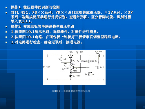
图10.7 由两只三极管组成的四种类型的复合管
当由于电源电压上升引起输出电压上升时,稳压过程由下列式子给出: Ui↑→Uo↑→Ub2↑→Ic2↑→Uc2↓→Ub1↓→Ube1↓→Uce1↑→Uo↓。 其实这个稳压过程的实质,就是电路的负反馈电路在起作用。 三极管串联调整型稳压电路的优点是:稳压效果好,带负载能力大,输出电压在一定范围内可调。
如果用三极管来代替限流电阻,就构成了三极管串联调整型稳压电路,如图10.3所示。
图10.3 最简单的三极管串联调整型稳压电路
2. 三极管串联调整型稳压电路的稳压过程 三极管串联调整型稳压电路的稳压过程如下: 当负载不变、输入电压Ui升高时,会引起输出电压Uo变高。由于稳压二极管两端的电压基本不变,所以b点的电压也基本不变,Ube=Ub-Uo值变小,根据三极管得输出特性,基极电流Ib和集电极电流Ic都要减小,导致Uce变大,于是抵消了Uo的升高,保持输出电压值基本稳定。当负载不变、输入电压Ui降低时,稳压过程与上述相反。 当输入电压不变、负载电流变大时,电流在电源内祖上的压降增加,会引起输出电压Uo降低。由于Ub基本不变,则Ube=Ub-Uo值变大,导致Uce跟随着变小,于是抵消了Uo的降低,保持输出电压值基本稳定。当输入电压不变、负载电流变小时,稳压过程与上述相反。
输出电压由下式决定: 一个输入直流电压为UI=15V、输出直流稳定电压为8~12V、最大负载电流为I0max=3A的实际电路如图10.8所示
图10.8 实用的三极管串联调整型稳压电路
1.三端固定输出式集成稳压器系列 常用的三端固定输出式集成稳压器有输出为正电压的W78××[u1] 系列和输出为负电压的W79××系列。如图10.9所示,为W78××系列的外形、电路符号及基本接法。W78××系列三端稳压块的输出电压有5V、6V、9V、12V、15V、18V和24V共七种规格,型号的后两位数字表示其输出电压的稳压值。例如,型号为W7805和W7812的集成块,其输出电压分别为5V和12V。 同一种规格的三端稳压块,在输出电流的大小上也有所不同,例如标注为7805、78M05和78L05的三端稳压块,其输出稳压值都是5V,但输出电流分别为1.5A、0.5A和0.1A(这个电流值都是指在满足一定散热条件下的最大输出电流值)。 W79××系列的稳压块其输出电压的规格与W78××系列相同,但其管脚功能与W78××系列不同。79××系列稳压块的1脚是输入端,2脚为接地端,3脚为输出端。79××系列稳压块的1脚是接地端,2脚为输入端,3脚为输出端。在使用时要特别引起注意。 [u1]此处的“W78××和W79××”是否应改为“CW78××和CW79××”?也可以不该,带C的是中国产的。
线性直流稳压电源

1设计任务描述1.1设计题目:线性直流稳压电源1.2 设计要求1.2.1 设计目的(1)掌握线性直流构成原理与设计方法;(2)熟悉模拟元件的选择,使用方法。
1.2.2 基本要求(1)220V交流输入电压,12V直流输出电压;(2)使用集成三端稳压器进行稳压输出,输出纹波系数<1%;(3)输出功率>5%。
1.2.3 发挥部分(1)输出电压线性可调;(2)估算出线性电源高效率(>50%)的使用范围。
2 绪论根据小功率稳压电源的构成,它是由电源变压器、整流、滤波和稳压器等四部分组成的,其结构图和稳压过程如下所示:直流稳压电源的作用是将交流电网的电压转化为直流电压,为放大电路提供直流工作电源。
各部分的工作过程是:(1) 电源变压器将交流电网提供的电压V1=220V变为所需要的V2=12V的交流电压;(2)通过整流电路将交流为12V的电压转变为脉动的直流电压V R,其峰值仍然为12V;(3)由于脉动的直流电压V R中还含有较大的纹波,必须通过滤波电路加以滤除,所以此过程是用滤波电路将纹波滤除,从而得到平滑的直流电压V F;(4)因为得到的直流电压V F还会随着电网电压的波动、负载和温度的变化而变化,因而在进行了整流、滤波之后,还需要进行稳压处理。
此过程中稳压电路的作用是当电网电压波动、负载和温度发生变化时,进一步滤波,维持输出直流电压为12V的稳定性和带载能力。
通过上述四个大过程,就大体上完成了直流稳压电源的工作。
然后,根据每一个部分的工作原理,可以进一步对电路的元器件进行选择和对电路进行连接。
整流电路的作用是将交流电变换成直流电完成这一任务主要是靠二极管的单向导电性的作用,因此二极管是构成整流电路的关键原件,在选择二极管的时候要了解其工作的电压,以方便对它合理的选择。
在一般的小功率整流电路中,常见的几种整流电路有单向、半波、全波桥式和倍压整流电路。
在分析整流电路时,一般二极管都是用其理想模型来进行处理,即正向导通电阻为零,反向电阻为无穷大。
Lm电源芯片布线指导
Lm系列电源芯片布线指导1.Both the designer and the CAD person need to be aware that the design of a switching power converter is only as good as its layout设计者和CAD布局者都要明白:开关转换器的设计仅仅是布局良好的一方面。
2.The overall subject of PCB design is an extremely wide one,embracing several test/mechanical/production issues and also in some cases compliance/regulatory issues.There is also a certain amount of physics/electromagnetics involved,PCB设计的总体具体是一个非常广泛,包括几个测试/机械/生产问题,并在某些情况下遵守/管理问题。
也有涉及到一些物理学和电磁学的问题。
3.we have provided recommended starting points for layout when using the popular LM267x,LM259x and LM257x families (Figure 2) The focus is on the step-down (Buck) Simple Switcher ICs from National, but the same principles hold for any topology and switching power application我们对布局提供建议的出发点是使用比较流行的LM267x、LM259x和LM257x系列,主要集中在降压(Buck)简单开关电源转换芯片,但是同样的原则在其它的任何拓补结构和开关电源应用中依然适用。
OMAPL137评估模块技术参考手册11
OMAP-L137 评估模块技术参考手册2008 DSP 开发系统 511345-0001 Rev. A 2009年2月15日第一章 OMAP-L137 EVM介绍第一章提供了omap-l137 EVM的描述,以及它的主要特点和电路框图1.1主要特点. . . . . . . . . . . . . . . . . . . . . . . . . . . . . . . . . . . .. . . . . . . . . . . . . . . . . . . . . . . . . .21.2 OMAP-L137功能性概述. . . . . . . . . . . . . . . . . . . . . . . . . . . . . . . . . . . . . . . . . . . . . . . . . . . 31.3 基本操作. . . . . . . . . . . . . . . . . . . . . . . . . . . . . . . . . . . . . . .. . . . . .. . . . . . . . . . . . . . . . 3 1.4 存储区映射. . . . . . . . . . . . . . . . . . .. . . . . . . . . . . . . . . . . . . . . . . . . . . . . . . . . . . . . . . . . . 3 1.5 启动开关设置. . . . . . . . .. . . .. . . . . . . . . . . . . . . . . . . . . .. . . . . . . . . . . . . . . . . . . . . . . . . 4 1.6 电源供应. . . . . . .. . . . . . . . . . . . . . . . . . . . . . . . . . . . . . .. . . . . . . . . . . . . . . . . . . . . . . . . 5 1.1主要特点:OMAP-L137 EVM自成体系(独立)的开发平台,此开发平台能让用户评估和开发TI OMAP-L137处理器系列应用。
音频工程师关于程控交流电源设计指南
音频工程师关于程控交流电源设计指南
音频工程师关于程控交流电源设计指南
LED工程实例赣州飞龙岛大桥照明设计理念
Q4调研出炉LED液晶电视面板走势超越CCFL
武汉新芯期待涅磐中芯代管模式或到终点
LED工程师必备产业六大应用领域及市场分析
奢侈消费转变3DLED电视带动实质体验消费
采用冶金结合方式LED照明散热难题告破
如何解决混合动力汽车功率模块中稳定性问题
系统结构与控制原理
升压+全桥逆变器和输出LC滤波器是大功率程控交流电源极为常用的拓扑之一。
如图1所示,这是一种两级非隔离拓扑,其第一级是升压级,用于把模块整流电压升压到实际峰值直流电压(>325V);第二级是逆变级,用于把峰值直流电压转变为交流电压,再经LC滤波器得到50Hz的交流输出电压。
全桥逆变器一般采用单极性控制方式,其特点是高频臂的两只功率管以较高的开关频率互补开关,保证可以得到理想的正弦输出电压波形;另两只功率管以较低的输出电压基波频率工作,从而很大程度上减小了开关损耗。
该全桥逆变器并不是一个桥臂始终为低频(输出基频),另一个桥臂始终为高频(载波频率),而是以半个输出电压周期切换工作,即同一个桥臂前半个周期工作在低频,后半周则工作在高频,这样就保证两个桥臂功率管工作在均。
- 1、下载文档前请自行甄别文档内容的完整性,平台不提供额外的编辑、内容补充、找答案等附加服务。
- 2、"仅部分预览"的文档,不可在线预览部分如存在完整性等问题,可反馈申请退款(可完整预览的文档不适用该条件!)。
- 3、如文档侵犯您的权益,请联系客服反馈,我们会尽快为您处理(人工客服工作时间:9:00-18:30)。
U2=Ui/1.2=12.5V
N1/N2=U1/U2=220/12.5=17.6
3)在满载情况下选择滤波电容的大 小(取5倍工频半周期)
R L C (3 5) T 2
C=5*T*Ii/(2Ui)
C=5*0.02*1/(2*15)*10^6=3333uf
用LM137设计一个输出1A的恒 压源,输出电压为-3~-10V
题目 11
成员:高彦飞 冯超 郭靖
题目要求
1)画出系统电路图,并画出变压器输出、滤波 电路输出及稳压输出的电压波形;画出变压器副边 电流的波形。 2)输入工频220V交流电的情况下,确定变压 器变比; 3)在满载情况下选择滤波电容的大小(取5 倍工频半周期); 4)求滤波电路的输出最大电压; 5)求电路中固定电阻阻值。
性能介绍
输出电压范围
电源稳压能力测试
THANK YOU
3300uf
耐压值:U=1.414*U2*1.1=19.4V 故电容选3300uF/50V的电解电容
4)求滤波电路的输出最大电压
5)求电路中固定电阻阻值
U
O
U
REF
U
F
REF
(1
R1 R2
)
U O 1 .2 (1
R2 R1
)
1.2(1+R1/120)=3~10 R2=180~880Ω
系统电路图
旁路 电位 器两 端纹 波电 压 用来改 善负载 的瞬态 响应。
滤波电 容 用来抵消输入端接线 较长时的电感效应, 防止产生自激振荡。
变压器输出电压波形
滤波电路输出电压波形
滤波电路输出电压波形
稳压输出的电压波形电的情况下,确定 变压器变比
