东崎计数器CB7说明书
里程计中文说明书
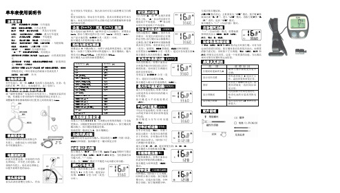
单车表使用说明书功能说明- SPD CURRENT SPEED / 行车速度. -ODO ODOMETER / 行车总里程.-DST TRIP DISTANCE / 单次行车里程. - MXS MAXIMUM SPEED / 最大行车速度. - A VS A VERAGE SPEED / 平均速度. - TM ELAPSED TIME / 行车时间.- RPM ROTATION PER MINUTE / 车轮转数. - CLK CLOCK (12H/24H )/时钟. - SCAN ( )ICON /自动循环显示. - “▲” “▼” COMPAPATOR / 对比提示- SETTING SPEED SCALE (km/h,m/h )/公里或英里设定- SETTING TYRE CIRCUMFERENCE / 胎圆周设定(60CM ~229CM )- SETTIN THE LAST V ALUE OF ODOMETER / ODO 原数值设定(即行前设定的距离公里或英里) -AUTO ON/OFF 开/关电池的安装打开电池门,将一粒AG13电池放入电池盒内,注意:电池的正极(+)向上,电池装好后,盖上电池门。
磁性传感器和磁体的安装将“磁性传感器”安装在自行车前叉上,和磁体安装在同一侧,传感器卡带可垫附件中的橡胶垫固定在前叉上。
调整磁铁和传感器的相对位置,使之间的距离为1mm 。
表座的安装使用表座的螺丝将表座固定在车把上,如锁扣过大可使用附件中的橡胶垫片。
电缆的固定沿前叉布置电缆,并用附件中的扎带固定,在车把上的电缆,必须绕在车把上,用尼龙扎带固定,以便不妨碍车把的活动。
表头的安装表头沿表座滑槽完全推入,有扣位可使表头不易拔出,拆出表头时可用力沿滑槽反方向推出。
检查安装情况:转动自行车前轮,看表头屏幕是否有讯号输入,如无反应或反应不太灵敏可适当的调整磁铁和传感器的相对位置。
公里(km/h )/ 英里(m/h )选择装入电池后15秒钟内(15秒后进入自动循环),屏幕显示km/h, 按动 左键可选择公里/小时(km/h )或英里(m/h )。
信inton CUB7P 8位小型编程计数器卡片说明书
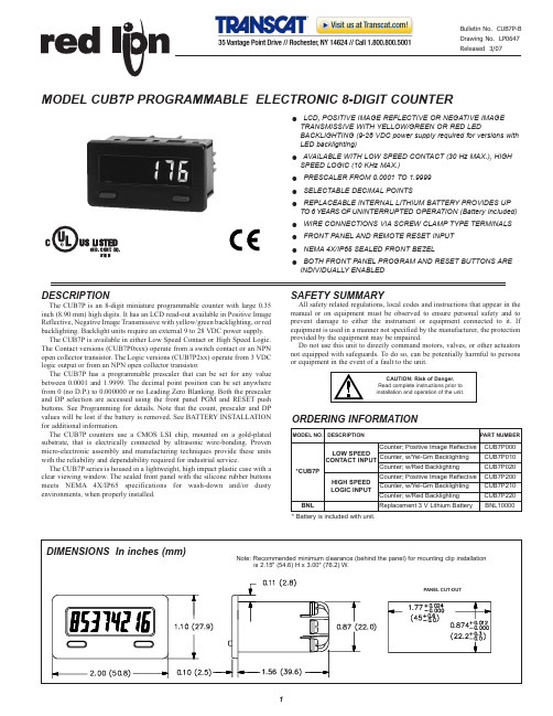
DESCRIPTIONThe CUB7P is an 8-digit miniature programmable counter with large 0.35inch (8.90 mm) high digits. It has an LCD read-out available in Positive Image Reflective, Negative Image Transmissive with yellow/green backlighting, or red backlighting. Backlight units require an external 9 to 28 VDC power supply. The CUB7P is available in either Low Speed Contact or High Speed Logic.The Contact versions (CUB7P0xxx) operate from a switch contact or an NPN open collector transistor. The Logic versions (CUB7P2xx) operate from 3 VDC logic output or from an NPN open collector transistor.The CUB7P has a programmable prescaler that can be set for any value between 0.0001 and 1.9999. The decimal point position can be set anywhere from 0 (no D.P.) to 0.000000 or no Leading Zero Blanking. Both the prescaler and DP selection are accessed using the front panel PGM and RESET push buttons. See Programming for details. Note that the count, prescaler and DP values will be lost if the battery is removed. See BATTERY INSTALLATION for additional information.The CUB7P counters use a CMOS LSI chip, mounted on a gold-plated substrate, that is electrically connected by ultrasonic wire-bonding. Proven micro-electronic assembly and manufacturing techniques provide these units with the reliability and dependability required for industrial service.The CUB7P series is housed in a lightweight, high impact plastic case with a clear viewing window. The sealed front panel with the silicone rubber buttons meets NEMA 4X/IP65 specifications for wash-down and/or dusty environments, when properly installed.SAFETY SUMMARYAll safety related regulations, local codes and instructions that appear in the manual or on equipment must be observed to ensure personal safety and to prevent damage to either the instrument or equipment connected to it. If equipment is used in a manner not specified by the manufacturer, the protection provided by the equipment may be impaired.Do not use this unit to directly command motors, valves, or other actuators not equipped with safeguards. To do so, can be potentially harmful to persons or equipment in the event of a fault to the unit.OLCD, POSITIVE IMAGE REFLECTIVE OR NEGATIVE IMAGE TRANSMISSIVE WITH YELLOW/GREEN OR RED LEDBACKLIGHTING (9-28 VDC power supply required for versions with LED backlighting)OAVAILABLE WITH LOW SPEED CONTACT (30 Hz MAX.), HIGH SPEED LOGIC (10 KHz MAX.)O PRESCALER FROM 0.0001 TO 1.9999O SELECTABLE DECIMAL POINTSOREPLACEABLE INTERNAL LITHIUM BATTERY PROVIDES UP TO 6 YEARS OF UNINTERRUPTED OPERATION (Battery Included)OWIRE CONNECTIONS VIA SCREW CLAMP TYPE TERMINALS O FRONT PANEL AND REMOTE RESET INPUT O NEMA 4X/IP65 SEALED FRONT BEZELOBOTH FRONT PANEL PROGRAM AND RESET BUTTONS ARE INDIVIDUALLY ENABLEDMODEL CUB7P PROGRAMMABLE ELECTRONIC 8-DIGIT COUNTER* Battery is included with unit.SPECIFICATIONS1. DISPLAY: 8-digit LCD, 0.35" (8.90 mm) high digits.2. POWER SOURCE: Replaceable Internal3.0 V lithium battery to provide up to 6 years of continuous operation. (Battery life is dependent upon usage. Contacts that remain closed for long periods of time reduce battery life.) 3. BACKLIGHT POWER REQUIREMENTS: 9 to 28 VDC; 35 mA. typical, 50 mA max. Above 26 VDC, derate max. operating temperature to 40°C. Must use NEC Class 2 or SELV rated power supply.4. SIGNAL INPUT: (LS terminal #4) See Count Edge under Programming for incrementing edge of input signal.Contact Input(CUB7P0xx):30 Hz max. from Switch Contact or solid state Transistor Switch to Common with a50% duty cycle. Contact burden7 µAmax. Logic Input(CUB7P2xx): 10 KHz max. from a 3.0V bipolar output or 200 Hz max.from a solid state Transistor Switch to Common with a 50% duty cycle. Contact burden 7 µA max.5. REMOTE RESET: 15 msec min. pulse width (active low) from 3.0 V bipolar output, an open collector transistor, or a switch contact to common.6. ENVIRONMENTAL CONDITIONS:Operating Temperature Range: 0 to 50°C Derate max. operating temperature to 40°C above 26 VDC (Backlight versions).Storage Temperature: -30 to 80°COperating and Storage Humidity: 85% max. relative humidity (non-condensing) from 0°C to 50°C.Vibration According to IEC 68-2-6:5 to 500 Hz, in X, Y, Z direction for 1.5 hours, 5g’s.Shock According to IEC 68-2-27:Operational 30 g, 11 msec in 3 directions. Altitude: Up to 2000 meters7. CERTIFICATIONS AND COMPLIANCES:SAFETYUL Listed, File # E137808, UL508, CSA C22.2 No. 14-M95LISTED by Und. Lab. Inc. to U.S. and Canadian safety standardsType 4X Indoor Enclosure rating (Face only), UL50IEC-61010-1, EN 61010-1: Safety requirements for electrical equipmentfor measurement, control, and laboratory use, Part 1.IP65 Enclosure rating (Face only), IEC 529ELECTROMAGNETIC COMPATIBILITYNotes1. Backlit powered units require a power line filter to be installed, RLCLFIL0000 or equivalent, so as not to impair the function of thebacklighting.Refer to EMC Installation Guidelines for additional information.8. CONNECTIONS: Wire clamping screw terminalsWire Strip Length: 0.3" (7.5 mm)Wire Gage: 30-14 AWG copper wireTorque: 5 inch-lbs (0.565 N-m) max.9. CONSTRUCTION: High impact plastic case with clear viewing window. The front panel meets NEMA4X/IP65 requirements for indoor use when properly installed. Installation Category I, Pollution Degree 2. Panel gasket and mounting clip included.10. WEIGHT: 2 oz. (57 grams) [with battery]900 MHz ± 5 MHz Immunity to EN 50082-2200 Hz, 50% duty cycle Electrostatic discharge EN 61000-4-2Level 2; 4 Kv contactLevel 3; 8 Kv air Electromagnetic RF fields EN 61000-4-3Level 3; 10 V/m80 MHz - 1 GHzFast transients (burst)EN 61000-4-4Level 4; 2 Kv I/OLevel 3; 2 Kv power 1 RF conducted interference EN 61000-4-6Level 3; 10 V/rms150 KHz - 80 MHz Simulation of cordless telephone ENV50204Level 3; 10 V/mEmissions to EN 50081-1RF interference EN 55022Enclosure class BEMC INSTALLATION GUIDELINESAlthough this unit is designed with a high degree of immunity to ElectroMagnetic Interference (EMI), proper installation and wiring methods must be followed to ensure compatibility in each application. The type of the electrical noise, source or coupling method into the unit may be different for various installations. In extremely high EMI environments, additional measures may be needed. The unit becomes more immune to EMI with fewer I/O connections. Cable length, routing and shield termination are very important and can mean the difference between a successful or a troublesome installation. Listed below are some EMC guidelines for successful installation in an industrial environment.1. Use shielded (screened) cables for all Signal and Control inputs. The shield (screen) pigtail connection should be made as short as possible. The connection point for the shield depends somewhat upon the application. Listed below are the recommended methods of connecting the shield, in order of their effectiveness.a. Connect the shield only at the panel where the unit is mounted to earthground (protective earth).b. Connect the shield to earth ground at both ends of the cable, usually whenthe noise source frequency is above 1 MHz.c. Connect the shield to common of the unit and leave the other end of theshield unconnected and insulated from earth ground.2. Never run Signal or Control cables in the same conduit or raceway with AC power lines, conductors feeding motors, solenoids, SCR controls, and heaters, etc. The cables should be run in metal conduit that is properly grounded. This is especially useful in applications where cable runs are long and portable two-way radios are used in close proximity or if the installation is near a commercial radio transmitter.3. Signal or Control cables within an enclosure should be routed as far away as possible from contactors, control relays, transformers, and other noisy components.4. In extremely high EMI environments, the use of external EMI suppression devices, such as ferrite suppression cores, is effective. Install them on Signal and Control cables as close to the unit as possible. Loop the cable through the core several times or use multiple cores on each cable for additional protection. Install line filters on the power input cable to the unit to suppress power line interference. Install them near the power entry point of the enclosure. The following EMI suppression devices (or equivalent) are recommended:Ferrite Suppression Cores for signal and control cables:Fair-Rite # 0443167251 (RLC #FCOR0000)TDK # ZCAT3035-1330ASteward #28B2029-0A0Line Filters for input power cables:Schaffner # FN610-1/07 (RLC #LFIL0000)Schaffner # FN670-1.8/07Corcom #1VR3Note: Reference manufacturer’s instructions when installing a line filter.5. Long cable runs are more susceptible to EMI pickup than short cable runs. Therefore, keep cable runs as short as possible.WIRING CONNECTIONSThe electrical connections are made via screw-clamp terminals located on the back of the unit. All conductors should meet voltage and current ratings for each terminal. Also, cabling should conform to appropriate standards of good installation, local codes and regulations. It is recommended that power supplied to the unit be protected by a fuse or circuit breaker. When wiring the unit, use the battery cover to identify the wire position with the proper function. Strip the wire, leaving approximately 1/4" bare wire exposed (stranded wires should be tinned with solder). Insert the wire under the screw-clamp and tighten down the screw until the wire is clamped in tightly. Each terminal can accept up to two: Lithium battery may explode if incinerated.INSTALLATION ENVIRONMENTThe unit should be installed in a location that does not exceed the maximum operating temperature and provides good air circulation. Placing the unit near devices that generate excessive heat should be avoided.The bezel should be cleaned only with a soft cloth and neutral soap product. Do NOT use solvents.Continuous exposure to direct sunlight may accelerate the aging process of the bezel.Do not use tools of any kind (screwdrivers, pens, pencils, etc.) to operate the push buttons of the unit.INSTALLATIONThe CUB7P meets NEMA4X/IP65 requirements for indoor use when properly installed. The units are intended to be mounted into an enclosed panel. The viewing window and reset button are factory sealed for a washdown environment. A sponge rubber gasket and mounting clip are provided for installing the unit in the panel cut-out.The following procedure assures proper installation:1. Cut panel opening to specified dimensions. Remove burrs and clean around panel opening.2. Carefully remove and discard the center section of the gasket.3. Slide the panel gasket over the rear of the counter body to the back of the bezel. Install CUB7P unit through the panel cut-out.4. Insert the mounting screws onto both sides of mounting clip. Tip of screw should NOT project from hole in mounting clip.5. Slide the mounting clip over the rear of the unit until the clip is against the back of the panel. The mounting clip has latching features which engage into mating features on the CUB7P housing.6. Note: It is necessary to hold the unit in place when sliding mounting clip into position.7. Alternately tighten each screw to ensure uniform gasket pressure. Visually inspect the front panel gasket. The gasket should be compressed to about 75 to 80% of its original thickness. If not, gradually turn mounting screws to further compress gasket.8. If the gasket is not adequately compressed and the mounting screws can no longer be turned, loosen mounting screws, and check that the mounting clip is latched as close as possible to the panel.9. Repeat from step #5 for tightening mounting screws.PROGRAMMING EXAMPLESSCALING A COUNTERExample:An encoder generates 600 pulses per foot. The Desired Display is tenths of inches. The Prescaler is determined using the formula below.Prescaler =Where:Desired Display = The number of DesiredDisplay units (revolutions, feet, 10ths of feet, meters, etc.).Number of Pulses = The number of pulsesrequired to achieve the Desired DisplayDecimal Point Value = The desired decimal pointplacement on the display.Example:Display tenths of inches when usingPrescaler = = 10/50 = 0.21 (inch) x 10 (Decimal Point Value)600 pulses/foot x 1 foot/ 12 inchesDesired Display Units x Decimal Point ValueNumber of PulsesTROUBLESHOOTINGFor further technical assistance, contact technical support at the appropriate company numbers listed.This page intentionally left blankLIMITED WARRANTYThe Company warrants the products it manufactures against defects in materials and workmanship for a period limited to two years from the date of shipment, provided the products have been stored, handled, installed, and used under proper conditions. The Company’s liability under this limited warranty shall extend only to the repair or replacement of a defective product, at The Company’s option. The Company disclaims all liability for any affirmation, promise or representation with respect to the products.The customer agrees to hold Red Lion Controls harmless from, defend, and indemnify RLC against damages, claims, and expenses arising out of subsequent sales of RLC products or products containing components manufactured by RLC and based upon personal injuries, deaths, property damage, lost profits, and other matters which Buyer, its employees, or sub-contractors are or may be to any extent liable, including without limitation penalties imposed by the Consumer Product Safety Act (P.L. 92-573) and liability imposed upon any person pursuant to the Magnuson-Moss Warranty Act (P.L. 93-637), as now in effect or as amended hereafter.No warranties expressed or implied are created with respect to The Company’s products except those expressly contained herein. The Customer acknowledges the disclaimers and limitations contained herein and relies on no other warranties or affirmations.。
Love Controls LCT216计时器 计数器 速度计说明书
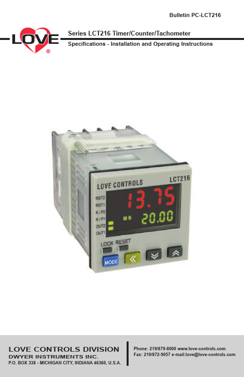
TABLE OF CONTENTSModel Number Identification . . . . . . . . . . . . . . . . . . . . . . . . . . . . . . . . . . . . . . . . . . . . . . . .3 Getting Started . . . . . . . . . . . . . . . . . . . . . . . . . . . . . . . . . . . . . . . . . . . . . . . . . . . . . . . . . .3 Installation3Panel Cutout Dimensions . . . . . . . . . . . . . . . . . . . . . . . . . . . . . . . . . . . . . . . . . . . . . .3 Mounting . . . . . . . . . . . . . . . . . . . . . . . . . . . . . . . . . . . . . . . . . . . . . . . . . . . . . . . . . . .4 Wiring Diagrams . . . . . . . . . . . . . . . . . . . . . . . . . . . . . . . . . . . . . . . . . . . . . . . . . . . . . . . . .5 Front Panel Key Functions . . . . . . . . . . . . . . . . . . . . . . . . . . . . . . . . . . . . . . . . . . . . . . . . .6 Security Features . . . . . . . . . . . . . . . . . . . . . . . . . . . . . . . . . . . . . . . . . . . . . . . . . . . . . . . .7 Timer Settings . . . . . . . . . . . . . . . . . . . . . . . . . . . . . . . . . . . . . . . . . . . . . . . . . . . . . . . . . . .8 Parameter Configuration . . . . . . . . . . . . . . . . . . . . . . . . . . . . . . . . . . . . . . . . . . . . . . .8 Timing Functions . . . . . . . . . . . . . . . . . . . . . . . . . . . . . . . . . . . . . . . . . . . . . . . . . . . . .9 Counter Settings . . . . . . . . . . . . . . . . . . . . . . . . . . . . . . . . . . . . . . . . . . . . . . . . . . . . . . . .10 Counter Configuration . . . . . . . . . . . . . . . . . . . . . . . . . . . . . . . . . . . . . . . . . . . . . . . .10 Counter Modes . . . . . . . . . . . . . . . . . . . . . . . . . . . . . . . . . . . . . . . . . . . . . . . . . . . . .13 Tachometer Settings . . . . . . . . . . . . . . . . . . . . . . . . . . . . . . . . . . . . . . . . . . . . . . . . . . . . .14 Tachometer Configuration . . . . . . . . . . . . . . . . . . . . . . . . . . . . . . . . . . . . . . . . . . . . .14 Tachometer Output Methods . . . . . . . . . . . . . . . . . . . . . . . . . . . . . . . . . . . . . . . . . . .14 Mixed Timer / Counter Settings . . . . . . . . . . . . . . . . . . . . . . . . . . . . . . . . . . . . . . . . . . . . .15 Mixed Timer / Counter Configuration . . . . . . . . . . . . . . . . . . . . . . . . . . . . . . . . . . . .15 DIP Switch Settings . . . . . . . . . . . . . . . . . . . . . . . . . . . . . . . . . . . . . . . . . . . . . . . . . . . . . .16 Specifications . . . . . . . . . . . . . . . . . . . . . . . . . . . . . . . . . . . . . . . . . . . . . . . . . . . . . . . . . .17 Precautions . . . . . . . . . . . . . . . . . . . . . . . . . . . . . . . . . . . . . . . . . . . . . . . . . . . . . . . . . . . .18MODEL NUMBER IDENTIFICATIONGETTING STARTED1.Install the control as described on page 4.2. Wire your control following the instructions on page 5. Please read the Precautionssection located at the end of this manual before wiring the control.INSTALLATIONMount the instrument in a location that will not be subject to excessive temperature, shock,or vibration. All models are designed for mounting in an enclosed panel.Select the position desired for the instrument on the panel. Prepare the panel by cutting and deburring the required opening per the panel cut out dimensions listed below. Follow the mounting instructions listed on page 4. Lastly, wire the controller per the appropriate wiring diagram listed on page 5.1 = 100 to 240 VAC0 = Transistor1 = Relay0 = NoneLCT216Panel Cut OutMOUNTING METHODStep 1:From the front of the panel, slide the controller housing through the cut out. The housing gasket should be against the housing flange before installing.Step 2:Slide the mounting collar over the housing from the rear of the panel.Step 3: Push the mounting collar forward until the bracket stops at the panel wall.Step 4: Insert and tighten the screws on the bracket to secure the controller in place.(The screw torque should be 0.8 kgf-cm).Mounting Bracket InstallationWIRINGTerminal IdentificationInput Connections NPNPNPCounter CP1CP2Reset1Reset2Timer GateReset1StartTachometerCP1Reset1Timer &Counter CP1Gate Reset1StartMulti-Function Input PINFRONT KEY FUNCTIONSKey functions are as follows:MODE: Pressing the Mode key advances the display to the next menuitem and saves any changed parameter values.UP ARROW: Increments a value or changes a menu item. If pressed whilein the home display, the set point value will be increased.DOWN ARROW: Decrements a value or changes a menu item. Ifpressed while in the home display, the set point value will be decreased.LEFT ARROW: Changes the selected digit to the left. This is used toquickly change set point values for large values.RESET: Clear and reset the PV display.LOCK: Press to enter secure mode. See Security Feature section formore information.SECURITY FEATURESThe Series LCT216 has two built-in security lock settings to prevent unauthorized personnel from changing parameter settings.The LoC1 setting affects all parameters in the controller. If LoC1 setting is enabled, the operator will have to unlock the controller to make any changes to the controller’s parametersThe LoC2 setting affects all parameters except the set point and the reset function. If LoC2 setting is enabled, the only parameters that the operator will be able to change are the set point and resetting the process value. In order to change any other parameters, the operator will have to unlock the control before making a change.In order to unlock the control, the operator must depress the MODE and LEFT ARROW key simultaneously.CONTROL OPERATION DESCRIPTIONHome DisplayThe HOME display is the normal display while the control is operating. If no errors or functions are active, the HOME display will indicate the process value on the top display and the set value on the bottom display. Below the set value, the current mode of operation will be shown as TAC (tachometer), CNT (counter), or TMR (timer). There will also be a descriptor for the time units and type of counter operation.While in the HOME display, the user can use the UP ARROW, DOWN ARROW, and LEFT ARROW keys to change the set point value. The RESET key will clear the process value. The LOCK key will enable the security feature.Parameter Configuration DisplayHolding the MODE KEY for 3 seconds will enter the parameter configuration display. Once in the parameter configuration display, the parameter will be listed in the top display and the value of that parameter will be listed in the bottom display. Pressing the MODE key will cycle through the parameters for the respective operation modes. The UP and DOWN arrows change the values of the parameters. The MODE key must be pressed to save any changes. Return to the HOME display by holding the MODE key for 3 seconds.TIMER SETTINGSThe timer function of the series LCT216 takes a signal input to start a timing sequence. The sequence can be paused using the GATE input or reset using RST1 input. Use the below parameters and timing functions to configure the timer.Parameter ConfigurationPV SVFUnC timE Sets the controller to function as a timer.t mode UP Sets the display to count up or down.downt otmd Sets the output timing functions. See the timing functionssection or page 9 for detail description of each timingfunction.t Unit Sets the display units of measure. See below table for alist of the available units.Table A: List of Timing UnitsT oUt 1Sets the pulse width (t) for output 1. The default output timeis0.02 seconds. If you wish the system to keep the operation ofthe output, please set the output time to 0.00 seconds.rtSr Sets the minimum pulse width at either 1 msec or 20 msec. inPtLC Sets the transistor input type to NPN or PNP. For contact input,the selection can be either PNP or NPN, but the selection willdetermine whether the connection is to terminal 11 or terminal 6.See the input connection diagrams on page 5.Timer FunctionsCOUNTER SETTINGSParameter configurationPV SVFUnC Cont Sets the controller to function as a counterCntFUn Select the counter to perform single stage counting, twostage counting, batch counting, total counting or dualcounting.STAGE1Controller has a single process value and set point value.Output 2 will be the same as output 1.STAGE2Controller has up to two set point and process values. Theoperation is based on the input modes and output types.bAtCH Controller can be set to count batch processes. In this mode,the counter will count up until it reaches the set value and then willincrement the batch present value by one. The process willcontinue until the batch set point value is reached.totAL Controller has a single set point. The display can show thepresent value since last reset or total counts.dUAL Controller will either add or subtract the counts from the twocounter inputs.C inPt Counter input mode can be selected to count up or down when acounter input signal is received.UP The present value will increase with each counter input signal.doun The present value will decrease with each counter input signal.Ud A Command up / down setting will increase or decrease thepresent value with each counter 1 input signal depending on ifcounter 2 input is engaged. When counter 2 input is engaged, eachcounter 1 input signal will decrease the count.Ud b Individual up / down setting will increase the present value with each counter 1 input signal and decrease with each counter 2 inputsignal.Ud C Quadrature up / down uses the order of the inputs to determine whether to count up or down. If counter input 1 leads counter input2, the unit will count up. If counter input 2 leads counter input 1, theunit will count down.C otmd Counter Output Mode determines the output operation of thecontrol. It also determines how the counter will function afterreaching the set point. See the output mode charts on page 13 formore information.C SPEd Counting Speed can be set from one count per second up to10,000 counts per second. This setting determines the minimuminput signal width.t oUt1Sets the pulse width (t) for output 1.t oUt2Sets the pulse width (t) for output 2.Point Sets the number of digits to the right of the decimal point on thedisplay.PSCALE Pre-Scale is used when converting the process value’s units ofmeasure. The pre-scale value would be set as the conversion factor.(Pv = Pv * PSCALE)PwErS Power Save feature allows the control to save the current processvalue upon loss of power.SAvE Save process value upon power lossCLEAr Clear process value upon power lossrtSr Minimum width of reset signal determines how long the resetterminals must be engaged to reset the device.inPtLC Input signal can be set for PNP or NPN. This parameterdetermines which wiring diagram should be used.Counter Output Mode ChartsOutput Modes S, T, and D can only be used with up/down counting inputs.TACHOMETER SETTINGSParameter ConfigurationPV SVFUnC tACH Sets the controller to function as a tachometer.tAotmd Tachometer Output Mode determines the output condition when theprocess value exceeds the set point value. See output mode chartsbelow for more information.C SPEd Maximum Input Frequency can be set from one count per second upto 10,000 counts per second.Point Sets the number of digits to the right of the decimal point on thedisplay.PSCALE Pre-Scale is used when converting the process value’s units ofmeasure. This value is commonly used to convert the inputfrequency (counts per second) to a rotational speed (rpm) using thebelow equation.Frequency (Hz) * Pre-Scale = Rotation Speed (rpm)Pre-Scale = 60 / n (where n = number of pulses perrevolution).St tAC Initial Power Up Interrupt delays the output from triggering for up to99.9 seconds.St AvG Input Filter allows the tachometer to average 2, 4, or 8 readings togive a more stable reading. (1= 2 data points, 2 = 4 data points, and3 = 8 data points).rtSr Minimum Width of Reset Signal determines how long thereset terminals must be engaged to reset the device.inPtLC Input signal can be set for PNP or NPN. This parameterdetermines which wiring diagram should be used.TIMER + COUNTER MIXED MODE SETTINGSParameter ConfigurationPV SVFUnC miX Sets the controller to function as a timer and counter.T mode Timer Mode sets the timer to count up or Down.T otmd Timer Output Mode sets the output timing functions. See thetiming functions section on page 9 for detail description of eachtiming function.t Unit Sets the display units of measure. See table A on page 8 for a listof the available units.C inPt Counter input mode can be selected to count up or down when acounter input signal is received.UP The present value will increase with each counter inputsignal.doun The present value will decrease with each counter inputsignal.C otmd Counter Output Mode determines the output operation of thecontrol. It also determines how the counter will function afterreaching the set point. See the output function tables on page 13for more information.C SPEd Counting Speed can be set from one count per second up to10,000 counts per second. This setting determines the minimuminput signal width.t oUt1Sets the pulse width (t) for output 1.t oUt2Sets the pulse width (t) for output 2.Point Sets the number of digits to the right of the decimal point on thedisplay.PSCALE Pre-Scale is used when converting the process value’s units ofmeasure. The pre-scale value would be set as the conversion factor.(Pv = Pv * PSCALE).PuErS Power Save feature allows the control to save the current processvalue upon loss of power.SAvE Save process value upon power lossCLEAr Clear process value upon power lossrtSr Minimum width of reset signal determines how long the resetterminals must be engaged to reset the device.inPtLC Input signal can be set for PNP or NPN. This parameterdetermines which wiring diagram should be used.DIP SWITCH SETTINGSThe Series LCT216 can be configured either using the configuration parameters discussed in the previous section or by using DIP switches located on the side of the housing. When the DIP switch setting is turned on, the parameters can be viewed, but not changed using the front panel.Table B: DIP Switch Parameter ListSPECIFICATIONSOperating Temperature Range: 32 to 122°F (0 to 50°C).Humidity Conditions: 35 to 85% RH (non-condensing).Control Output Ratings: (Out 1) Relay: SPST 5A at 250 VAC, Transistor: NPN Open collector 100 mA / 30 VDC residual voltage = 1.5 VDC max; (Out 2) Relay: SPST 5A at 250 VAC, Transistor: NPN Open collector 100 mA / 30 VDC residual voltage = 1.5 VDC max.Weight: 4 oz (114 g).Reset Time: 0.001 seconds minimum.Inputs: Dry contact, PNP, or NPN.Timing Functions: 14 pre-programmed timing functions.Supply Voltage: 100 to 240 VAC 50 / 60 Hz.Power Consumption: Less than 10 VA.Internal Power Supply: 12 VDC ±10%, 100 mA..Display: Two-line 6 digit negative transmissive LCD display.Agency Approvals: CE, UL.1.Always use recommended solder-less terminals: Fork terminals with isolation(M3 screw, width 7.0 mm), hole (diameter 3.2 mm). Screw size: M3x6.5 (with6.8x6.8 square washer). Recommended tightening torque: 0.4 N.m ().Applicable wire: solid/twisted wire of 2 mm2, 12 AWG to 24 AWG. Please be sure to tighten them properly.2.Prevent dust or metallic debris from falling into the device and causemalfunctions.3.DO NOT modify or uninstall the device.4.DO NOT use empty terminals.5.Make sure the wires are correctly connected to proper terminals.6.Keep away from high-voltage and high-frequency environment duringinstallation in case of interference.7.Prevent using the device in premises which contain: dust or corrosive gas, highhumidity, high radiation, vibration and shock.8.LCT216 is an open-type device. Make sure to install it in an enclosure toprevent dust, humidity in case of an electric shock.9.Please make sure the power cables and signal device are installed correctlybefore switching on the power; otherwise serious damage may occur.10.DO NOT touch the terminals or repair the device when the power is on;otherwise an electric shock may occur.11.Please wait for one minute after the power is switched off to allow the capacitorto discharge and DO NOT touch the internal wiring within this period.e dry cloth to clean the device. DO NOT use acid or alkaline liquid to cleanthe device.©Copyright 2015 Dwyer Instruments, Inc Printed in U.S.A. 4/15 FR#443702-00 Rev. 2 LCT216 is an OPEN-TYPE device. They are intended for installation completely withinan overall panel and for use in counting or timing applications. If it will cause series injury to workers or damages on other equipment when used in a dangerous environment, please make sure it is installed in an automatic safety protection device.1. When the power is on, DO NOT touch the AC terminals in case an electric shockmay occur.2. Make sure the power is disconnected when you check the unit inside.。
RAD7 说明书

4 . 9 . 管理背景 6 0 5 .P C 连接 6 1 5 . 1R S 2 3 2 串口 6 1 5 . 1 . 1能力 6 1 5 . 1 . 2硬件桥接器 6 1 5 . 1 . 3软件桥接器 6 1 5 . 1 . 4应用 6 1 5 . 1 . 5R A D 7 串口的技术规格 6 2 5 . 1 . 6串口输出 6 2 5 . 2捕捉 1 . 2 6 4 5 . 3传输 6 5 5 . 4R A D L I N K 6 5 5 . 4 . 1 能力 6 5 5 . 4 . 2要求 6 5 5 . 4 . 3R A D 7 远程指挥格式 6 6 5 . 4 . 4特别键 6 6 5 . 4 . 5特别命令 6 7 6 .维修 6 8 6 . 1附件使用和维护 6 8 6 . 1 . 1干燥剂 6 8 6 . 1 . 1 . 1实验干燥设备 6 9 6 . 1 . 1 . 2 小干燥管 (小管)6 9 6 . 1 . 1 . 3层叠式干燥管 6 9 6 . 1 . 2过滤器 7 0 6 . 1 . 3电池 7 0 6 . 1 . 4实时时钟和非易失内存 7 1 6 . 1 . 5打印机和适配器 7 1 6 . 2操作范围 7 1 6 . 3服务和维修 7 2 6 . 3 . 1校准 7 2 6 . 3 . 2维修 7 2 6 . 3 . 3运输 7 3 6 . 3 . 4升级 7 3 6 . 4R A D 7 规格 7 3
o 3 0 . 4 C
3 4 . 1 6p C i / l(注释 1 ) 0 . 5 0 3C P M ( p C i / l )(注释 2 ) 0 . 2 4 4C P M ( p C i / l )(注释 2 ) 2 %l s i g m a (注释 4 、5 ) p C i / l ) C P M (注释 3 ) 1 . 9 9( 4 . 1 0( p C i / l ) C P M(注释 3 )
计数器说明书2
WSD-ZH-09A计数器使用说明手册杭州威士德喷码技术有限公司服务电话:400-685-2815杭州威士德喷码技术有限公司是专门经销和生产喷码设备和耗材的一家优秀企业,从事喷码行业多年,有着非常丰富的经验。
为了适应广大用户的生产需求,特为水泥行业开发WSD-ZH-09 型计数器,该计数器使用简单,计数准确,使用方便,可以用一台主机最多连接12个计数器窗口,可在不同的地方随时观察计数数值,子窗口链接距离1000米。
可减少人工计数人员的工作量,降低误差,以一个年产100万吨的水泥厂为例,0.5%的误差是(1000000吨*20包/吨*0.5%)=100000包,这样的误差对于水泥企业来说无疑是巨大的,还容易造成企业利益流失及客户信任度下降。
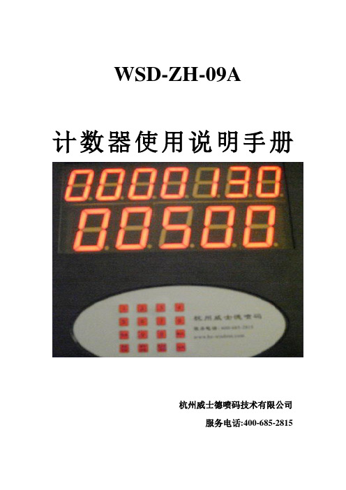
设备面板显示:上面7位数码管为计数总和,总计数为9999999,可自动循环计数。
下面一行为单次车装量,最大值为59999。
使用方法:开机显示:月份日期星期以及时间1.时间的设定:当时间不准确时请按累加数/时间键,机器将显示年二位。
月二位,日二位,星期一位,空一位,小时二位,分钟二位。
如:2009年2月27号星期五9:55分,将显示成:按正确的数字键将修改闪烁那位的数字并前进一位,如有错误可按取消键退格。
最后按确认修改保存,回到初时时间界面。
如不保存只能关电源。
2.计包学习:本产品可以适应任何长度、任何流水线速度的包装产品的计数,主要是通过计包学习来完成的,通过对水泥厂的流水线进行速度和包长的综合检测,当设备安装完成(即接近开关和红外感应检测都正常)后,先必须进行计包长度学习。
按清零/学习键,屏幕将出现表示第一次学习(按取消可退出),开动流水线,让包过红外对管,此时屏幕下行会出现一数字,如:07 08。
07表示接近开关的计数值,08表示光电开关的计数基值。
此数字表示一包在红外对管接收到信号时接近开关翻转次数,建议此数据要大于5小于16,按确认完成,这时候会出现表示第二学习,共学习四次,每次按确认完成。
琦胜计数器说明书CONCH
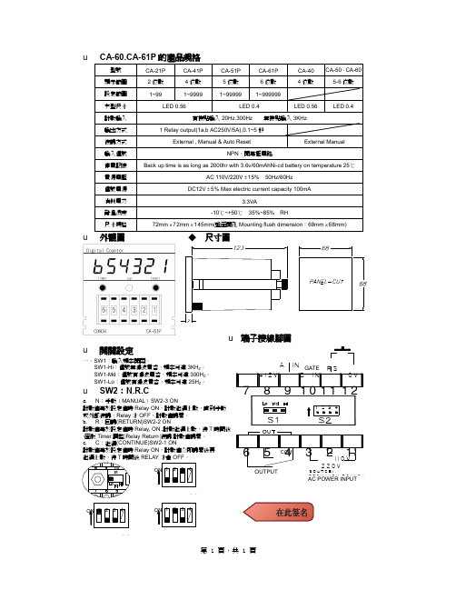
CA-60.CA-61P 的產品規格
型號 顯示範圍 設定範圍 字型尺寸 計數輸入 輸出方式 復歸方式 輸入信號 停電記憶 電源電壓 信號電源 消耗電力 耐溫濕度 尺寸規格 CA-21P 2 位數 1~99 CA-41P 4 位數 1~9999 LED 0.56 CA-51P 5 位數 1~99999 CA-61P 6 位數 1~999999 LED 0.56 無接點輸入 3KHz LED 0.4 CA-40 4 位數 CA-50、CA-60 5-6 位數
LED 0.4 有接點輸入 20Hz.300Hz
1 Relay output(1a,b AC250V/5A),0.1~5 秒 External , Manual & Auto Reset NPN,開集極電路 Back up time is as long as 2000hr with 3.6v/60mAhNi-cd battery on temperature 25 ℃ AC 110V/220V ± 15% 50Hz/60Hz External Manual
COM
AC POWER INPUT
S2
ON 1 2 3 4
ON 1 2 3 4
S2
S2
第 1 頁,共 1 頁
GATE ㆒、SW1:輸入頻率開關。 SW1-Hi:信號無濾波電容,頻率可達 3KHZ。 SW1-Md:信號有濾波電容,頻率可達 300HZ。 SW1-Lo:信號有濾波電容,頻率可達 25HZ。
u
SW2:N.R.C
a. N:手動(MANUAL)SW2-3 ON 計數值等於設定值時 Relay ON,計數繼續㆖數,直到手動 或外部復歸,Relay 才 OFF,計數值歸零。 b. R:回歸(RETURN)SW2-2 ON 計數值等於設定值時 Relay, ON ,計數繼續㆖數,待 T 時間後 (面板 Timer 調整)Relay Return(復歸)計數值歸零。 c. C:繼續(CONTINUE)SW2-1 ON 計數值等於設定值時 Relay ON,計數值立即歸零後再 繼續㆖數,待 T 時間後 RELAY 才會 OFF。
东崎 TOKY CA计数器操作说明书
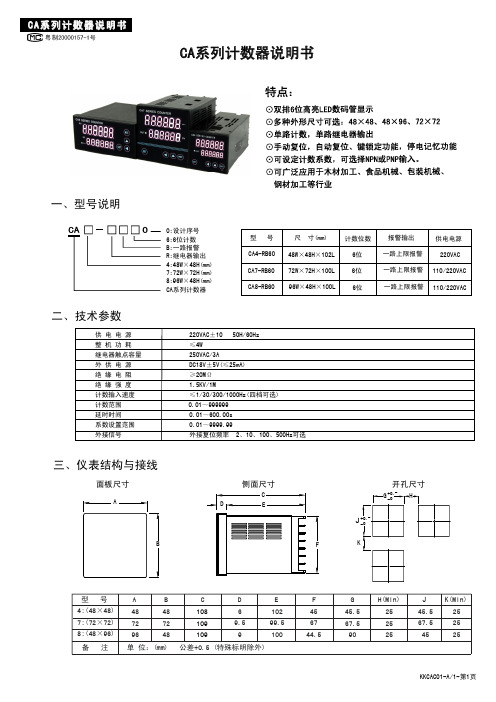
CA系列计数器说明书一、型号说明二、技术参数0:设计序号 6:6位计数B:一路报警R:继电器输出4:48W×48H(mm) 7:72W×72H(mm)8:96W×48H(mm)型 号尺 寸(mm)CA系列计数器说明书CA系列计数器三、仪表结构与接线CA4-RB60CA7-RB60CA8-RB6048W×48H×102L 72W×72H×100L 96W×48H×100L计数位数6位6位6位报警输出一路上限报警一路上限报警一路上限报警供电电源220VAC110/220VAC 110/220VAC4:(48×48)7:(72×72)8:(48×96)487296型 号A H(Min) GBCD EF J48724810810910969.5910299.510045.567.59025252545.567.545456744.5K (Min)252525面板尺寸 侧面尺寸 开孔尺寸备 注 单 位:(mm) 公差+0.5%(特殊标明除外)J 220VAC±10% 50H/60Hz ≤4W250VAC/3ADC18V±5V(≤25mA) ≥20MΩ1.5KV/1M≤1/30/300/1000Hz(四档可选)0.01~600.00s 0.01~9999.99外接复位频率 2、10、100、500Hz可选供 电 电 源整 机 功 耗继电器触点容量外 供 电 源绝 缘 电 阻绝 缘 强 度计数输入速度计数范围延时时间系数设置范围外接信号0.01~999999五、仪表操作流程注:若有改动恕不另行通知,接线请参照仪表接线图。
18VDC 码轮M 感应头接近开关POWER OUTGNDCPIN GNDCA仪表18VDC POWER OUT GNDCPIN GNDCA仪表测量状态测量状态按 键按SET键按 、 键改变预置值参数修改状态输入速度选择按SET键按SET键系数设定按SET键按SET键按SET键外接信号频率选择按SET键输出方式选择输出延时时间(S)按SET键掉电保护按SET键六、计数器输出方式逻辑图继电器输出方式为N、F、R、C四种CA8接线图CA7接线图CA4接线图按SET键按键锁定等级按SET键≥3S②①= Level0:没有锁定功能= Level1:锁RST键= Level2:锁 、△键= Level3:锁 、△、RST键②按键锁定等级( )①在菜单中选择NPN或者PNP后请将电路 板上对应的插针短接(默认为NPN) S1NPN PNPS1 NPN PNPNPN或PNP选择:NPN常开:NPN常闭:PNP常开:PNP常闭小数点选择(最多两位小数)。
计数、计米、计时、频率、转速使用说明书 1 XMT-50a XMT-50a

XMT-50a十段计时器显示仪!提请注意:1。
仪表在通电使用中,不允许将机芯移出机壳,不能随意触摸或接近后面板,以免触电危险。
2.仪表的安装及调试应由技术人员来完成。
第一部分产品介绍§1、产品概述XMT—A型系列智能化仪表是以先进的单片机及微电子技术为中心,应用霍尔传感器或旋转编码器,由北京智能拓维技术研究所设计制作而成的新一代计数、计时、计米、频率、速度等仪表,广泛应用于现代工程系统中。
其应用领域现以渗透到国防技术、航空、航天、铁路、冶金、化工、电力、农业等国民经济各部门以及日常生活中。
该系列仪表功能强,使用方便灵活,性能稳定可靠,精度高,主要特点如下:1.一机多用,功能齐全,任意选择,方便用户使用;2.①计数器/计米器可外接旋转编码器和霍尔传感器使用②,每种方式又可分为带倍率和不带倍率两种;3、①计时器集正计时.倒计时于一体,正.反计时共10种延时范围.②每一种延时范围内有10个时间段可任意选择;4、频率和转速表具有两大功能,其中频率计数又分为,1~9999HZ和0.1~999.9HZ两个档,输出控制配有6种继电器工作方式。
5.六种继电器方式可任意选择;6.对输入输出信号实行光电隔离,软硬件加看门狗功能,使仪表抗干扰能力强.7.仪表采用智能化的工作模式,用户可根据实际需要,通过面板上的触摸键,灵活地改变仪表的工作方式和参数设置。
§2、综合技术参数1、仪表工作环境:温度50℃以下;湿度90%以下;2、仪表精度:0。
2---0。
5级3、标准模拟信号输出:①电流输出:4--20mA②电压输出:0—5V4、整机功耗:3VA5、供电电源:①、仪表内部不含交流开关电源:直接输入AC220V50HZ。
②、仪表内部含交流开关电源:交流输入可在85V—265V50HZ之间。
6、采用国际通用面板面板上采用触摸按键。
通过按键所设定的值掉电时不丢失。
7、外型尺寸/开孔尺寸48×48/44×4448×96/44×9296×48/92×4496×96/91×91160×80/15 8仪表端子接线图48×48/44×4448×96/44×9296×48/92×4448×48/44×44§3、仪表安装与注意事项:1、仪表的安装:仪表的安装形式是嵌入式,应安装在厚度为1—3。
XSN智能计数器使用说明书

XSN智能计数器使用说明书目录1、概述 (1)2、型号规格 (3)3、技术规格 (6)3.1 基本技术规格 (6)3.2 选配件技术规格 (7)4、安装与接线 (9)5、参数一览表 (14)6、操作 (19)6.1 面板及按键说明 (19)6.2 参数设置说明 (20)6.3 预置输出设定值的设置方法 (20)6.4 密码设置方法 (21)6.5 其它参数的设置方法 (21)7、功能及相应参数说明 (23)7.1 计数及显示 (23)7.1.1 计数 (23)7.1.2 清零 (25)7.1.3 显示锁定 (27)7.1.4 输入类型为D的仪表 (27)7.2 预置输出 (29)7.3 变送输出 (31)7.4 通信接口 (32)7.5 打印接口及打印单元 (33)8、抗干扰措施 (35)概述1、概述XSN系列智能计数器与各类脉冲信号的传感器配合,用于数量、长度、位移的记录、测量、变换、显示、传送和控制。
分低速(10Hz以下)和高速两种类型最高计数频率10kHz0.0001~45.000宽范围计数比率显示方式分为S型和L型S型仪表显示范围:-19999~45000,小数点位置可设定。
可以选择多计数比率方式。
L型仪表显示范围:-9999999~9999999,小数点位置可设定。
输入类型为2的仪表,输入双相正交脉冲,自动识别正、反向运动。
2点预置输出。
2种输出方式,延时恢复及自动清零功能外部控制清零,加/减计数,显示锁定功能变送输出可将测量、变换后的显示值以标准电流、电压形式输出供其它设备使用全透明、高速、高效的网络化通信接口,实现计算机与仪表间完全的数据传送和控制。
独有的控制权转移功能使计算机可以直接控制仪表的报警输出和变送输出。
读取一次测量数据的时间小于10ms 提供测试软件,组态软件和应用软件技术支持概述具备带硬件时钟的打印接口和打印单元,实现手动、定时打印功能,如果选配智能打印单元,可实现多台仪表共用一台打印机XSN系列仪表采用单片机嵌入式组合设计,硬件扩充性强,软件平台灵活,可以扩展开关量输入、定时、程序顺序控制等,不局限于标准功能。
STEP7常用功能块说明
STEP7常用功能块说明STEP7 常用功能块说明1. SFB0 "CTU" SFB1 "CTD" SFB2 "CTUD" SFB4 "TON" SFB5 TOF兼容IEC61131-3的计数和计时功能块2. SFB41 "CONT_C" SFB42 "CONT_S" SFB43 "PULSEGEN"用于PID控制41---连续42---离散43---用于将一个模拟量转化为与之对应的周期性开关量脉冲信号,该脉冲的占空比与模拟量的数值大小成正比.3. SFC0 "SET_CLK" SFC1 "READ_CLK"用于读写PLC中的系统时间4. SFC14 "DPRD_DAT" SFC15 "DPWR_DA T"用于读写DP从站中的一致性数据如:读写用DP通讯的变频器中的控制字5. SFC20 "BLKMOV" SFC21 "FILL"块拷贝,块填充6. SFC46 "STP" SFC47 "WAIT"SFC46 使PLC进入STOP状态,挺有用的:可以当软件陷阱,或利用上位控制PLC停机7. SFC60 "GD_SND" SFC61 "GD_RCV"MPI的GD通讯8.IEC Function BlocksFC22 "LIMIT" FC25 "MAX" FC27 "MIN"FC22 ---限幅输出FC25,FC27 --- 3个数比大小9.PID Control BlocksFB41/42/43 同SFB41 "CONT_C" SFB42 "CONT_S" SFB43 "PULSEGEN"FB58 "TCON_CP" FB59 "TCONT_S" 用于温度控制PID10.Ti-S7 Converting BlocksFC105 "SCALE" FC106 "UNSCALE"模拟量输入输出的比例和数据类型转换11、SFC1 读取系统时钟12、SFC3 启动/停止运行时间定时器13、OB1:主程序循环14、OB10--OB17:在设置的日期和时间启动15、OB20--OB23:延时后启动16、OB30--OB38:以设定的时间为周期17、OB40--OB47:检测到来自外部模块的中断请求时启动18、OB55:DPV1中断(PROFIBUS-DP中断)目录1 组织块1-11.1 组织块(OB)概述................................................................................................ 1-11.2 程序循环组织块(OB1)....................................................................................... 1-41.3 时钟中断组织块(OB10到OB17) ....................................................................... 1-6 1.4 时间延迟中断组织块(OB20 到OB23).............................................................. 1-10 1.5 周期性中断组织块(OB30 到OB38) ................................................................. 1-12 1.6 硬件中断组织块(OB40到OB47) ..................................................................... 1-14 1.7 状态中断OB(OB 55)........................................................................................ 1-161.8 更新中断OB(OB 56)........................................................................................ 1-171.9 制造商特定中断OB(OB57).............................................................................. 1-181.10 多值计算中断组织块(OB60)............................................................................ 1-19 1.11 同步周期性中断OB(OB 61 到OB 64)............................................................... 1-21 1.12 I/O冗余出错OB(OB70).................................................................................... 1-22 1.13 CPU冗余出错OB(OB72)................................................................................. 1-241.14 通讯冗余出错OB(OB73) ................................................................................. 1-27 1.15 时间出错组织块(OB80)................................................................................... 1-281.16 电源出错组织块(OB81)................................................................................... 1-301.17 诊断中断组织块(OB82)................................................................................... 1-321.18 插入/删除模块中断组织块(OB83) ................................................................... 1-34 1.19 CPU硬件故障组织块(OB84) ........................................................................... 1-37 1.20 优先级出错组织块(OB85) ............................................................................... 1-38 1.21 机架故障组织块(OB86)................................................................................... 1-421.22 通讯出错组织块(OB87)................................................................................... 1-451.23 处理中断OB(OB 88)........................................................................................ 1-471.24 后台组织块(OB90) .......................................................................................... 1-481.25 启动组织块(OB100、OB101和OB102) .......................................................... 1-50 1.26 编程出错组织块(OB121)................................................................................. 1-551.27 I/O访问出错组织块(OB122) ............................................................................ 1-572 SFC的公共参数2-12.1 通过输出参数RET_V AL判断出错...................................................................... 2-1 2.2 异步SFC的REQ、RET_V AL和BUSY参数的含义............................................. 2-4 目录用于S7-300/400系统和标准功能的系统软件x A5E00446508-013 复制功能和块功能3-13.1 使用SFC20 “BLKMOV”复制存储区域............................................................... 3-1 3.2 使用SFC81 “UBLKMOV”不间断地复制变量..................................................... 3-4 3.3 使用SFC21 “FILL”初始化存储区....................................................................... 3-6 3.4 使用SFC22 “CREAT_DB”创建数据块............................................................... 3-8 3.5 使用SFC23 “DEL_DB”删除数据块.................................................................. 3-103.6 使用SFC24 “TEST_DB”测试数据块................................................................ 3-123.7 使用SFC25 “COMPRESS”压缩用户存储器.................................................... 3-133.8 使用SFC44 “REPL_V AL”传送一个替换值到累加器1...................................... 3-15 3.9 使用SFC82 “CREA_DBL”在装载存储器中生成数据块................................... 3-16 3.10 使用SFC83 “READ_DBL”从装载存储器的数据块中读取数据........................ 3-19 3.11 使用SFC84 “WRIT_DBL”在装载存储器中写入数据块.................................... 3-213.12 使用SFC85 “CREA_DB”创建数据块............................................................... 3-234 用于控制程序执行的SFC 4-14.1 使用SFC43 “RE_TRIGR”重新触发循环时间监视............................................. 4-1 4.2 使用SFC46 “STP”将CPU切换为STOP............................................................. 4-1 4.3 使用SFC47 “WAIT”延时用户程序执行.............................................................. 4-2 4.4 使用SFC35 “MP_ALM”触发多处理器中断........................................................ 4-34.5 使用SFC104 “CiR”控制CiR............................................................................... 4-45 用于处理系统时钟的SFC 5-15.1 使用SFC0 “SET_CLK”设定TOD....................................................................... 5-15.2 使用SFC1 “READ_CLK”读取时间.................................................................... 5-25.3 使用SFC48 “SNC_RTCB”同步子时钟.............................................................. 5-35.4 使用SFC100 “SET_CLKS”设定时间日期和TOD状态....................................... 5-46 用于处理运行系统计时器的SFC 6-16.1 运行时间定时器................................................................................................. 6-16.2 使用SFC101 “RTM”控制运行时间定时器.......................................................... 6-2 6.3 使用SFC2 “SET_RTM”设置运行时间定时器..................................................... 6-4 6.4 使用SFC3 “CTRL_RTM”启动和停止运行时间定时器....................................... 6-5 6.5 使用SFC4 “READ_RTM”读取运行时间定时器.................................................. 6-66.6 使用SFC64 “TIME_TCK”读取系统时间............................................................ 6-77 用于传送数据记录的SFC 7-17.1 读写一条数据记录............................................................................................. 7-17.2 使用SFC54 “RD_DPARM”读取定义的参数...................................................... 7-3 7.3 使用SFC102 “RD_DPARA”读取预定义参数..................................................... 7-4 7.4 使用SFC55 “WR_PARM”写动态参数............................................................... 7-57.5 使用SFC56 “WR_DPARM”写一条数据记录...................................................... 7-7 7.6 用SFC57 “PARM_MOD”将参数分配给模块..................................................... 7-8 7.7 使用SFC58 “WR_REC”写入数据记录............................................................. 7-117.8 使用SFC59 “RD_REC”读一个数据记录.......................................................... 7-13 7.9 SFC 55到59的进一步出错信息....................................................................... 7-18目录用于S7-300/400系统和标准功能的系统软件A5E00446508-01 xi8 符合PNO AK 1131的DPV1 SFB 8-18.1 使用SFB “RDREC”从DP从站读一个数据记录.................................................. 8-1 8.2 使用SFB53“WRREC”将数据记录写入DP从站.................................................. 8-3 8.3 用SFB54“RALRM”STATUS[3]从DP从站接收中断.......................................... 8-58.4 用SFB75“SALRM”向DP主站发送中断............................................................ 8-149 用于处理时钟中断的SFC 9-19.1 处理时钟中断.................................................................................................... 9-19.2 SFC 28到31的特征........................................................................................... 9-29.3 使用SFC28 “SET_TINT”设置日时钟中断.......................................................... 9-4 9.4 使用SFC29 “CAN_TINT”取消时钟中断............................................................. 9-5 9.5 使用SFC30 “ACT_TINT”激活时钟中断............................................................. 9-69.6 使用SFC31 “QRY_TINT”查询日时钟中断......................................................... 9-710 用于处理延时中断的SFC 10-110.1 处理延时中断.................................................................................................. 10-110.2 使用SFC32 “SRT_DINT”启动延时中断........................................................... 10-3 10.3 使用SFC34 “QRY_DINT”查询日时钟中断...................................................... 10-410.4 使用SFC33 “CAN_DINT”取消延时中断.......................................................... 10-511 用于处理同步出错的SFC 11-111.1 屏蔽同步出错.................................................................................................. 11-111.2 使用SFC36 “MSK_FLT”屏蔽同步出错.......................................................... 11-10 11.3 使用SFC37 “DMSK_FLT”解除屏蔽同步出错................................................ 11-1111.4 使用SFC38 “READ_ERR”读取出错寄存器................................................... 11-1212 用于处理中断和异步出错的SFC 12-112.1 延迟和禁用中断和异步出错............................................................................. 12-112.2 使用SFC39 “DIS_IRT”禁用新中断和异步出错的处理..................................... 12-3 12.3 使用SFC40 “EN_IRT”启用新中断和异步出错的处理...................................... 12-5 12.4 使用SFC41 “DIS_AIRT”延迟更高优先级中断和异步出错的处理.................... 12-712.5 使用SFC42 “EN_AIRT”启用处理较高优先级的中断和异步出错..................... 12-813 用于诊断的SFC 13-113.1 系统诊断......................................................................................................... 13-113.2 使用SFC6 “RD_SINFO”读取OB启动信息....................................................... 13-1 13.3 使用SFC51 “RDSYSST”读取系统状态列表或部分列表.................................. 13-4 13.4 使用SFC52 “WR_USMSG”将自定义诊断事件写入诊断缓冲区................... 13-10 13.5 使用SFC78 “OB_RT”确定OB程序运行时间.................................................. 13-14 13.6 使用SFC87 “C_DIAG”诊断当前连接状态...................................................... 13-1813.7 使用SFC103 “DP_TOPOL”识别DP主站系统的总线拓扑.............................. 13-2314 用于更新过程映像和处理位域的SFC和SFB 14-114.1 使用SFC26 “UPDA T_PI”更新过程映像输入表................................................ 14-1 14.2 使用SFC27 “UPDA T_PO”更新过程映像输出表.............................................. 14-3 14.3 使用SFC79 “SET”在I/O区域中设置位域......................................................... 14-5 14.4 使用SFC 126 “SYNC_PI”在同步循环中更新过程映像分区输入表................. 14-6 14.5 使用SFC 127 “ISO_PO”在同步循环中更新过程映像分区输出表.................... 14-8 14.6 使用SFC80 “RSET”复位I/O区域中的位域..................................................... 14-10 14.7 使用SFB 32 “DRUM”实现一个操作序列....................................................... 14-11 目录用于S7-300/400系统和标准功能的系统软件xii A5E00446508-0115 用于寻址模块的系统功能15-115.1 使用SFC5 “GADR_LGC”查询模块的逻辑基址................................................ 15-1 15.2 使用SFC49 “LGC_GADR”查询属于一个逻辑地址的模块插槽....................... 15-315.3 使用SFC50 “RD_LGADR”查询模块的所有逻辑地址...................................... 15-516 用于分布式I/O的SFC 16-116.1 使用SFC7 “DP_PRAL”在DP主站上触发硬件中断.......................................... 16-1 16.2 用SFC11 “DPSYC_FR”同步DP从站组........................................................... 16-4 16.3 用SFC12 “D_ACT_DP”激活和取消激活DP从站........................................... 16-10 16.4 用SFC13 “DPNRM_DG”读取DP从站的诊断数据(从站诊断) ........................ 16-14 16.5 使用SFC14 “DPRD_DAT”读取DP标准从站的连续数据................................ 16-1816.6 使用SFC15 “DPWR_DAT”将连续数据写入到DP标准从站........................... 16-2017 用于全局数据通讯的SFC 17-117.1 使用SFC60 “GD_SND”发送一个GD信息包.................................................... 17-117.2 通过SFC61 “GD_RCV”编程接受已接收到的GD信息包.................................. 17-418 通讯和S7基本通讯的概述18-118.1 S7通讯块和S7基本通讯块之间的差别............................................................ 18-118.2 数据的一致性.................................................................................................. 18-418.3 S7通讯块概述................................................................................................. 18-618.4 用于S7基本通讯的功能块总览........................................................................ 18-819 S7通讯19-119.1 用于S7通讯的SFB/FB和SFC/FC的公用参数.................................................. 19-1 19.2 用于组态的S7连接的SFB启动例行程序.......................................................... 19-5 19.3 SFB对故障如何反应........................................................................................ 19-719.4 通过SFB8/FB8“USEND”进行无协调的数据发送............................................. 19-9 19.5 通过SFB/FB9“URCV”进行无协调的数据接收............................................... 19-12 19.6 通过SFB/FB12 “BSEND”发送分段数据........................................................ 19-15 19.7 通过SFB/FB13 “BRCV”接收分段数据........................................................... 19-18 19.8 通过SFB/FB15“PUT”向远程CPU写入数据................................................... 19-21 19.9 通过SFB/FB14GET”从远程CPU中读取数据................................................. 19-24 19.10 使用SFB16“PRINT”将数据发送到打印机...................................................... 19-27 19.11 通过SFB 19“START”在远程设备上开始一个暖重启或冷重启...................... 19-33 19.12 通过SFB 20“STOP”将远程设备切换到STOP状态........................................ 19-36 19.13 通过SFB 21“RESUME”在远程设备上开始一个热重启.................................. 19-38 19.14 使用SFB 22“STA TUS”查询远程伙伴的状态................................................. 19-40 19.15 通过SFB23 “USTATUS”接收远程设备的状态改变....................................... 19-42 19.16 通过SFC62 “CONTROL”查询属于SFB实例的连接状态............................... 19-44 19.17 通过FC62 “C_CNTRL”查询连接状态............................................................ 19-46 19.18 S7通讯SFB/FB的工作存储器要求................................................................. 19-48目录用于S7-300/400系统和标准功能的系统软件A5E00446508-01 xiii20 用于未组态S7连接的通讯SFC 20-120.1 通讯SFC的公用参数....................................................................................... 20-120.2 用于未组态S7连接的通讯SFC的出错信息...................................................... 20-2 20.3 使用SFC65 “X_SEND”将数据发送给在本地S7站外的一个通讯伙伴.............. 20-7 20.4 通过SFC66 “X_RCV”从本地S7站以外的通讯伙伴中接收数据....................... 20-8 20.5 通过SFC68 “X_PUT”将数据写入本地S7站以外的通讯伙伴.......................... 20-1120.6 通过SFC67 “X_GET”从本地S7站以外的通讯伙伴中读取数据..................... 20-13 20.7 通过SFC69 “X_ABORT”中止已存在的、到本地S7站以外的通讯伙伴的连接20-15 20.8 使用SFC72 “I_GET”从本地S7站内的一个通讯伙伴上读取数据.................... 20-16 20.9 使用SFC73 “I_PUT”将数据写入到本地S7站内的一个通讯伙伴.................... 20-1820.10 通过SFC74 “I_ABORT”中止已存在的、到本地S7站内的通讯伙伴的连接.... 20-2021 PROFInet 21-121.1 SFC112、113和114背景信息......................................................................... 21-121.2 使用SFC112 “PN_IN”更新用于PROFInet组件的用户程序接口的输入........... 21-4 21.3 使用SFC113 “PN_OUT”更新用于PROFInet组件的用户程序接口的输出....... 21-521.4 使用SFC114 “PN_DP”更新DP互连................................................................ 21-622 生成与块相关的消息22-122.1 关于使用SFB生成块相关消息的介绍.............................................................. 22-122.2 使用SFB 36 “NOTIFY”生成无需确认的块相关消息........................................ 22-5 22.3 使用SFB31 “NOTIFY_8P”生成无确认显示的块相关消息............................... 22-7 22.4 使用SFB 33 “ALARM”生成需要确认的块相关消息....................................... 22-10 22.5 使用SFB35 “ALARM_8P”生成针对八个信号的带有关联值的块相关消息..... 22-13 22.6 使用SFB34 “ALARM_8”生成针对八个信号的不附带关联值的块相关消息.... 22-16 22.7 使用SFB37 “AR_SEND”发送归档数据......................................................... 22-18 22.8 使用SFC10 “DIS_MSG”禁止与块相关的消息、与符号相关的消息以及组状态消息................................................................ 22-2022.9 使用SFC9 “EN_MSG”启用块相关、符号相关和组状态消息......................... 22-22 22.10 用于生成与块相关的消息的SFB的启动特性................................................. 22-2422.11 用于生成与块相关的消息的SFB如何响应故障.............................................. 22-25 22.12 使用SFC生成与块相关的消息简介................................................................ 22-2622.13 使用SFC17 “ALARM_SQ”生成可确认的与块相关的消息以及使用SFC18 “ALARM_S”生成永久确认的与块相关的消息................................................ 22-2922.14 使用SFC19 “ALARM_SC”查询上一ALARM_SQ/ALARM_DQ进入事件消息的确认状态.......................................................... 22-3222.15 使用SFC 107 “ALARM_DQ”和108 “ALARM_D”生成可确认和永久确认的块相关消息............................................................ 22-3322.16 使用SFC105 “READ_SI”读取动态系统资源.................................................. 22-3522.17 使用SFC106 “READ_SI”读取动态系统资源.................................................. 22-3823 IEC定时器和IEC计数器23-123.1 使用SFB 3“TP”生成一个脉冲.......................................................................... 23-123.2 使用SFB 4“TON”生成一个接通延迟................................................................ 23-3 23.3 使用SFB 5“TOF”生成一个关闭延迟................................................................ 23-523.4 使用SFB 0 “CTU”递增计数............................................................................. 23-723.5 使用SFB 1 “CTD”递减计数............................................................................. 23-823.6 使用SFB2 “CTUD”递增/递减计数................................................................... 23-9目录用于S7-300/400系统和标准功能的系统软件xiv A5E00446508-0124 IEC功能24-124.1 概述................................................................................................................. 24-124.2 IEC功能的技术数据......................................................................................... 24-324.3 日期和时间作为复杂数据类型......................................................................... 24-5 24.4 时间功能......................................................................................................... 24-624.5 比较DATE_AND_TIME变量......................................................................... 24-10 24.6 比较STRING变量.......................................................................................... 24-1324.7 编辑数值....................................................................................................... 24-1624.8 STL示例........................................................................................................ 24-1724.9 STL示例........................................................................................................ 24-1824.10 编辑STRING变量.......................................................................................... 24-1924.11 转换数据类型格式......................................................................................... 24-2425 用于集成控制的SFB 25-125.1 使用SFB41/FB41 “CONT_C”实现连续控制.................................................... 25-1 25.2 使用SFB42/FB42 “CONT_S”进行步控制........................................................ 25-8 25.3 使用SFB43/FB43 “PULSEGEN”生成脉冲.................................................... 25-1425.4 PULSEGEN块的实例.................................................................................... 25-2526 用于紧凑型CPU的SFB 26-126.1 通过SFB44 “Analog”使用模拟量输出进行定位............................................... 26-1 26.2 通过SFB46 “DIGITAL”使用数字量输出进行定位.......................................... 26-13 26.3 使用SFB47 “COUNT”控制计数器................................................................. 26-23 26.4 使用SFB48 “FREQUENC”控制频率测量...................................................... 26-28 26.5 使用SFB49 “PULSE”控制脉宽调制............................................................... 26-32 26.6 使用SFB60 “SEND_PTP”发送数据(ASCII,3964(R)) .................................. 26-35 26.7 使用SFB61 “RCV_PTP”接收数据(ASCII,3964(R)) .................................... 26-38 26.8 使用SFB62 “RES_RCVB”删除接收缓冲区(ASCII,3964(R))...................... 26-41 26.9 使用SFB63 “SEND_RK”发送数据(512(R)) ................................................... 26-43 26.10 使用SFB64 “FETCH RK”获取数据(RK 512) ................................................. 26-47 26.11 使用SFB65 “SERVE_RK”接收和提供数据(RK 512) ..................................... 26-5226.12 SFB 60至65的附加出错信息......................................................................... 26-5727 用于H CPU的SFC 27-127.1 在H系统中使用SFC90 “H_CTRL”控制操作.................................................... 27-128 集成功能(对于带集成I/O的CPU) 28-128.1 SFB29(HS_COUNT)....................................................................................... 28-128.2 SFB30(FREQ_MES)....................................................................................... 28-328.3 SFB38(HSC_A_B).......................................................................................... 28-428.4 SFB39(POS)................................................................................................... 28-529 Plastics Techology 29-129.1 SFC63 (AB_CALL) ......................................................................................... 29-130 诊断数据30-130.1 诊断数据结构概述........................................................................................... 30-130.2 诊断数据......................................................................................................... 30-230.3 通道专有诊断数据的结构................................................................................ 30-4目录用于S7-300/400系统和标准功能的系统软件A5E00446508-01 xv31 系统状态列表(SSL) 31-131.1 系统状态列表(SSL)概述.................................................................................. 31-1 31.2 部分SSL列表的结构........................................................................................ 31-3 31.3 SSL-ID ............................................................................................................ 31-431.4 可能的部分系统状态列表................................................................................ 31-5 31.5 SSL-ID W#16#xy11 - 模块标识...................................................................... 31-631.6 SSL-ID W#16#xy12 - CPU特征...................................................................... 31-731.7 SSL-ID W#16#xy13 - 存储区域...................................................................... 31-931.8 SSL-ID W#16#xy14 - 系统区........................................................................ 31-1031.9 SSL-ID W#16#xy15 - 块类型........................................................................ 31-1231.10 SSL-ID W#16#xy19 - 模块LED的状态.......................................................... 31-13 31.11 SSL-ID W#16#xy1C - 组件标识.................................................................... 31-15 31.12 SSL ID W#16#xy25 - 将过程映像分区分配到OB.......................................... 31-18 31.13 SSL-ID W#16#xy32 - 通讯状态数据............................................................. 31-21 31.14 SSL-ID W#16#0132,索引为W#16#0005的部分列表的数据记录摘录....... 31-22 31.15 SSL-ID W#16#0132,索引为W#16#0008的部分列表的数据记录摘录....... 31-23 31.16 SSL-ID为W#16#0132、索引为W#16#000B的部分列表摘录的数据记录.... 31-25 31.17 SSL-ID为W#16#0132、索引为W#16#000C的部分列表摘录的数据记录.... 31-26 31.18 SSL-ID W#16#0232,索引为W#16#0004的部分列表的数据记录摘录....... 31-27 31.19 SSL-ID W#16#xy71 - H CPU的组信息......................................................... 31-28 31.20 SSL-ID W#16#xy74 - 模块LED的状态.......................................................... 31-31 31.21 SSL-ID W#16#xy75 - H系统中切换的DP从站.............................................. 31-33 31.22 SSL-ID W#16#xy90 - DP主站系统信息........................................................ 31-35 31.23 SSL-ID W#16#xy91 - 模块的状态信息.......................................................... 31-37 31.24 SSL-ID W#16#xy92 - 机架/站的状态信息..................................................... 31-41 31.25 SSL-ID W#16#xy95 - 扩展DP主站系统信息................................................. 31-44 31.26 SSL-ID W#16#xyA0 - 诊断缓冲区................................................................ 31-46 31.27 SSL-ID W#16#00B1 - 模块的诊断信息......................................................... 31-47 31.28 SSL-ID W#16#00B2 - 对应物理地址的诊断数据记录1................................. 31-49 31.29 SSL-ID W#16#00B3 - 带逻辑基址的模块诊断数据....................................... 31-5031.30 SSL-ID W#16#00B4 - DP从站的诊断数据.................................................... 31-5132 事件32-132.1 事件和事件标识符........................................................................................... 32-132.2 事件等级1 - 标准OB事件................................................................................. 32-3 32.3 事件等级2 - 异步出错...................................................................................... 32-3 32.4 事件等级3 - 异步出错...................................................................................... 32-4 32.5 事件等级4 - 停止事件和其它模式改变............................................................ 32-7 32.6 事件等级5 - 模式运行期事件......................................................................... 32-10 32.7 事件等级6 - 通讯事件.................................................................................... 32-11 32.8 事件等级7 - H/F事件..................................................................................... 32-12 32.9 事件等级8 - 模块的诊断事件......................................................................... 32-14 32.10 事件等级9 - 标准用户事件............................................................................. 32-16 32.11 事件等级A和B - 自由用户事件...................................................................... 32-17 32.12 保留的事件等级............................................................................................. 32-18目录用于S7-300/400系统和标准功能的系统软件xvi A5E00446508-0133 SFC和SFB列表33-133.1 按编号排序的SFC列表.................................................................................... 33-1 33.2 按字母排序的SFC列表.................................................................................... 33-4 33.3 按编号排序的SFB列表.................................................................................... 33-7 33.4 按字母排序的SFB列表.................................................................................... 33-9 参考书目词汇表索引用于S7-300/400系统和标准功能的系统软件A5E00446508-01 1-11 组织块1.1 组织块(OB)概述何为组织块?组织块(OB)是指CPU的操作系统与用户程序之间的接口。
东崎温控表资料

温控器根据温度传感器采样的信号读取实际温度,然后将这个实际温度值与设定温度值进行比较,采用智能PID控制算法输出一个模拟量或者开关量驱动继电器或者大功率执行机构实现加热或者冷却控制,并将实际温度值恒定控制在设定值范围内。
热工温度控制仪表全新设计AI208智能温控表全新软/硬件设计,具有极高的性价比。
TC/RTD通用信号输入,内置针对不同控制对象的多种PID算法,以满足不同行业的控制需求,使客户达到最佳的控制效果。
软件有加热,制冷,多种功AI708人工智能调节仪TE-W/AI208智能温控表TM拨码设定温控表AI808程序段控制调节仪AI518万能输入温控表4:48H×48W×96L6:96H×48W×96L7:72H×72W×96L8:48H×96W×96L9:96H×96W×96L80:80H×160W×96L80H×160W×96L 4:48H×48W×96L 6:96H×48W×96L 7:72H×72W×96L4:45H×45W6:92H×45W7:69H×69W8:45H×92W4:45H×45W■ 型号说明■ 型号说明■ 产品图片及功能特点特点★ 热电偶/热电阻/模拟信号通用软件选择输入★ 双PID算法,带自整定功能★ 多种控制输出选择,可选4~20mA线性输出★ 二路报警,具有多种报警方式可选★ 丰富的尺寸选择,超大的数码管显示★ 具有RS485通讯功能,ModBUS-RTU协议★ 超工业级EMC等级测试,可靠性更高■ 型号说明■ TE-W系列输入信号表(原TE输入信号表详见产品说明书)■ 系列接线图(上排为TE-W系列,下排为原TE系列)TE4-WTE6/8/9-WTE7-W1267345RTDT CAL13141516171819AC 220VRELAY 1718SSR■ TE-W系列外观及安装尺寸(原TE系列尺寸请参看产品说明书)面板尺寸ABC EDFG KJ +0.5-+0.5-H型 号AH(Min)GBCDEFJ K (Min)252525252530302525252525303045.54567.59292155.5764589.56744.591.575.51559188.588.588.588.583836.59999131397.597.597.597.597.596964896724896801604848729696160804:(48*48)6:(96*48)7:(72*72)8:(48*96)9:(96*96)80:(80*160)16:(160*80)45.59267.5459276155.5开孔尺寸东崎仪表侧面尺寸AC 220V123454 5109876-+TCAL RTD RELAY AC/DC 100~240V+-SSR OUT TE467 8 123 45 9103 34 56 7BB RTAL1-+85~265V AC/DC NCNO R E L A YT G SCR+-SSR 输入信号代码输入类型测量范围分辨率精度输入阻抗K型热电偶J型热电偶E型热电偶T型热电偶S型热电偶PT100CU50CU100-20~1300℃-20~1000℃-20~600℃-20~400℃-20~1700℃-199.9~610.0℃-50.0~150.0℃-50.0~150.0℃1℃1℃1℃1℃1℃0.1℃0.1℃0.1℃0.5%F.S 0.5%F.S 0.5%F.S 0.5%F.S 0.5%F.S 0.5%F.S 0.5%F.S 0.5%F.S>100KΩ>100KΩ>100KΩ>100KΩ>100KΩ(0.2mA)(0.2mA)(0.2mA)TE6/96 54 3 44 3327 891016 15 16 1514 13 1217 181920 R E L A YNCNOAL~220V ~110V G SCRTB A B Rt TCS S R传感器显示控制表时间继电器人机界面 信号隔离器电力仪表脉冲转速线速度工频频率表 旋转编码器接近开关固态继电器热工类显示控制仪表计数器 系列记录仪巡检仪电工仪表电力保护装置滤波器补偿器制冷专用控制仪表OUTTE765 4 32176716 15141317 18 19 -+TC Rt BBA NC RELAYNO AL~220v/110V CMYCMMYCYCMYK■ 接线图AI208-4AI208-7AI208-6/8/9■ 外观及安装尺寸面板尺寸ABC EDFG KJ +0.5-+0.5-H型 号AH(Min)GBCDEFJ K (Min)252525252530302525252525303045.54567.59292155.5764589.56744.591.575.51559188.588.588.588.583836.59999131397.597.597.597.597.596964896724896801604848729696160804:(48*48)6:(96*48)7:(72*72)8:(48*96)9:(96*96)80:(80*160)16:(160*80)45.59267.5459276155.5开孔尺寸侧面尺寸东崎仪表OUT OUT OUTSSRPOWER ALALALRELAY 5551013141516171819131211131211101415161617181819981098767644332211543213NC COM NO 100~240VAC/DC POWER POWER100~240V AC/DC100~240V AC/DC TCRTDRTD -SSR++ SSR --+TC RELAY - +TCRTDNO COM NC RELAY 传感器显示控制表时间继电器人机界面信号隔离器电力仪表脉冲转速线速度工频频率表 旋转编码器接近开关固态继电器热工类显示控制仪表计数器系列记录仪巡检仪电工仪表电力保护装置滤波器补偿器制冷专用控制仪表■ AI208通用输入系列输入信号表(单输入系列详见产品说明书)输入信号代码输入类型测量范围分辨率精度输入阻抗K型热电偶J型热电偶E型热电偶T型热电偶PT100CU50CU100-50~999℃-50~999℃-50~850℃-50~400℃-199~650℃-50~150℃-50~150℃1℃1℃1℃1℃1℃1℃1℃0.5%F.S 0.5%F.S 0.5%F.S 0.5%F.S 0.5%F.S 0.5%F.S 0.5%F.S>100KΩ>100KΩ>100KΩ>100KΩ(0.2mA)(0.2mA)(0.2mA)CMYCMMYCYCMYK■ 型号说明拨码选择:A:进工拨码 B:国产拨码输入信号:10:表示1路通用信号输入报警输出: B: 表示一路报警控制输出: R: 继电器控制输出 S: 逻辑输出 K:可控硅控制输出(订做)供电电源: 空:220V AC (可订做AC 110V或DC 24V)外形尺寸(mm):4:48H×48W×100L 6:96H×48W×100L 7:72H×72W100LTM系列拨码设定智能温控表TM□□-□□□□型号TM□-SB10B TM□-RB10B TM□-SB10A TM□-RB10A 1路报警1路报警逻辑输出继电器输出1路报警1路报警逻辑输出继电器输出报警输出控制输出■ 型号种类注:4尺寸为85~265V AC/DC,6、7尺寸为220V供电,110V需订做■ 外观及安装尺寸48.048.045+0.53045+0.5251004548.096.0100904591253072.072.067.567.5321410067■ 接线图TM4TM6TM7东崎仪表123334455987610NCNOR E L A YR E L A Y85~265V AC/DCBB A Rt AL NCALS S R传感器显示控制表时间继电器人机界面信号隔离器电力仪表脉冲转速线速度工频频率表 旋转编码器接近开关固态继电器热工类显示控制仪表计数器 系列记录仪巡检仪电工仪表电力保护装置滤波器补偿器制冷专用控制仪表TM4TM6TM7CMYCMMYCYCMYK富士变频器、富士接触器、富士开关按钮、富士温控表、富士断路器、富士触摸屏、富士P L C 三菱变频器、三菱接触器、和泉开关按钮、R K C温控表、三菱断路器、三菱触摸屏、三菱P L C 西门子变频器、西门子接触器、西门子开关按钮、西门子P L C 、西门子断路器、西门子触摸屏A B B变频器、A B B接触器、A B B开关按钮、A B B断路器、A U T ON I C S 光电开关、欧姆龙光电海利普变频器、丹佛斯变频器、日立变频器、东芝变频器、三肯变频器、三晶变频器、L G变频器、L G接触器、天得开关按钮、天得限位开关、L G断路器、L G P L C施耐德变频器、施耐德接触器、施耐德开关按钮、施耐德断路器、施耐德P L C士林变频器、士林接触器、康沃变频器、A U T ON I C S温控表、台安断路器、A U T ON I C S 行程开关安川变频器、艾默生变频器、富士开关按钮、松下变频器、松下P L C、富士P L C台达变频器、英威腾变频器、欧姆龙行程开关、正泰接触器、正泰断路器、台达触摸屏、台达P L C 富士继电器、和泉继电器、红波开关按钮、欧姆龙温控表、欧姆龙触摸屏、欧姆龙P L C。
WAGO 750-404 000-001 24V 二进制脉冲计数器说明书

https:///750-404/000-001Up Counter; Release InputData sheet | Item number: 750-404/000-001This counter records 24 V binary pulses and transmits the counter status to the fieldbus system.Counting is enabled and inhibited via the GATE input.Digital outputs DO 1 and DO 2 can be set using the control byte.The control byte sets or resets the counter.Technical dataNumber of digital outputs 2Number of counters 1Signal type Voltage Signal type (voltage)24 VDC Counter depth 32 bits Input current (typ.) 6 mA Output current per channel 0.5 AOutput currentshort-circuit-protected Switching frequency (max.)100 kHz Voltage range for signal (0)−3 … +5 VDC Voltage range for signal (1)15 … 30 VDCData width32-bit data; 8-bit control/status Supply voltage (system)5 VDC; via data contacts Current consumption (5 V system supply)70 mASupply voltage (field)24 VDC (-15 … +20 %); via power jumper contacts (power supply via blade contact;transmission via spring contact)Isolation500 V system/field Number of incoming power jumper contacts 2Number of outgoing power jumper contacts2Connection dataConnection technology: inputs/outputs8 x CAGE CLAMP®Connection type 1Inputs/outputsSolid conductor0.08 … 2.5 mm² / 28 … 14 AWGFine-stranded conductor0.08 … 2.5 mm² / 28 … 14 AWGStrip length8 … 9 mm / 0.31 … 0.35 inchesPhysical dataWidth12 mm / 0.472 inchesHeight100 mm / 3.937 inchesDepth69.8 mm / 2.748 inchesDepth from upper-edge of DIN-rail62.6 mm / 2.465 inchesMechanical dataMounting type DIN-35 railMaterial dataColor light grayHousing material Polycarbonate; polyamide 6.6Fire load 1.562 MJWeight49.6 gConformity marking CEEnvironmental requirementsAmbient temperature (operation)0 … +55 °CSurrounding air temperature (storage)-25 … +85 °CProtection type IP20Pollution degree (5) 2 per IEC 61131-2Operating altitude0 … 2000 m / 0 … 6562 ftMounting position horizontal (standing/lying); vertical Relative humidity (without condensation)95 %Vibration resistance4g per IEC 60068-2-6Shock resistance15g per IEC 60068-2-27EMC immunity to interference per EN 61000-6-2, marine applications EMC emission of interference per EN 61000-6-4, marine applications Exposure to pollutants per IEC 60068-2-42 and IEC 60068-2-43 Permissible HS contaminant concentration at a relative humidity 75 %10 ppm2contaminant concentration at a relative humidity 75 %25 ppmPermissible SO2Commercial dataProduct Group15 (Remote I/O)**********27-24-26-05*********27-24-26-05ETIM 8.0EC001601ETIM 7.0EC001601PU (SPU) 1 StückPackaging type BoxCountry of origin VKOrg Germany DEGTIN4045454429744Customs tariff number VKOrg Germany853********Approvals and certificatesGeneral approvalsApprovalStandardCertificate nameEACBrjansker ZertifizierungsstelleTP TC 020/2011EAC RU C-DE.AM02.B.00087/19KCNational Radio Research AgencyArticle 58-2, Clause 3MSIP-REM-W43-CTM750ULUnderwriters Laboratories Inc. (ORDINARY LOCATIONS)UL 508E175199 Sec.1Approvals for marine applicationsApprovalStandardCertificate nameABSAmerican Bureau of Shipping-22-2219060BSHBundesamt fuer Seeschifffahrt und Hydrographie-1104BVBureau Veritas S.A.-13453/E0 BV DNVDNV Germany GmbHDNV-CG-0339,Aug.2021TAA0000194KRKorean Register of Shipping-KR HMB05880-AC001LRLloyds Register EMEA -LR22180952TA PRSPolski Rejestr Statków -TE/2236/880590/19RINARINA Germany GmbH-ELE343521XG001Approvals for hazardous areasApprovalStandardCertificate nameATEXTUEV Nord Cert GmbH EN 60079-0CCC CNEXCNCA-C23-012020312310000213 (Ex ec IIC T4 Gc)EACBrjansker ZertifizierungsstelleTP TC 012/2011EAC RU C-DE.AM02.B.00163/19 (2Ex nA IIC T4Gc X)IECExTUEV Nord Cert GmbH IEC 60079-0IECEx_TUN_14.0035_X (Ex ec IIC T4 Gc)INMETROTÜV Rheinland do Brasil Ltda.IEC 60079-0BR-Ex_TÜV 12.1297 XULUnderwriters Laboratories Inc. (HAZARDOUS LOCATIONS)UL 121201E198726 Sec.1Compliance Search Environmental Product Compliance750-404/000-001Documentation ManualProduct Manual Up/ Down counter V 1.2.0pdf371.40 KBSystem Manual WAGO I/O System 750 / 753V 3.1.011.05.2022pdf8495.90 KBSystem Manual Series 750/753System Description750/753 Series I/O-System ‒ General Product Informationpdf953.35 KBOverview on WAGO-I/O-SYSTEM 750 approvalspdf770.48 KBUse in Hazardous EnvironmentsV 1.0.0pdf1007.06 KBBid Text750-404/000-00119.02.2019xml 4.05 KB750-404/000-00109.10.2017doc 24.00 KBCAD/CAE-DataCAD data2D/3D Models 750-404/000-001CAE data EPLAN Data Portal 750-404/000-001WSCAD Universe 750-404/000-001 ZUKEN Portal 750-404/000-001Device Files Device DriverWAGO USB Service Kabel Treiber / Serie 750 und 8576.5.3.010.09.2014zip4721.96 KBDownloadsEnvironmental Product ComplianceSubject to changes. Please also observe the further product documentation! Current addresses can be found at: 。
mp21b七参数组合测井仪使用说明书

快速操作指南缆头电压:电缆头接点处的电压,此电压随遥测挂接仪器不同而变化。
总线电压:遥测下挂点的电压,此接点为遥测和下挂仪器的通讯总线,此处电压不随遥测挂接仪器不同而变化,如无特殊说明,下文所述工作电压均指此电压。
曼码地址:0道-总线电压;1道-流量;2道-密度;3道-持水;4道-压力井温;5道-压力;6道-井温;7道-伽马; 8道-未用;9道-磁定位。
注:6道数据是实际井温测量值,而4道数据测量捆绑在压力探头上的PT1000的温度值,它用于补偿压力值;仪器刻度:总线电压:线性刻度,计数值2340对应30V电压,4096计数值对应52.5V。
流量刻度:测后查图版。
密度刻度:对数刻度,需在作业现场实时刻度。
持水刻度:测后查图版。
井温刻度:线性刻度,计数值1600对应0℃,10600计数值对应100℃。
压力刻度:为非线形刻度,所需的刻度系数可从仪器配送光盘获取。
仪器供电:正压(+30V~+54V)为仪器采集电路正常工作电压,因仪器采用开关电源供电,供电电压越高,仪器工作电流越小,如下所示:仪器采集电路工作电压: +30V~+54V,推荐工作电压+38V(0道记数3000HZ 左右),因仪器不是采用恒流供电,故仪器供电操作以此电压为准。
MP21B-YCWY 3+X(遥测+磁定位、压力、井温)仪工作电流:50mA±10%mA MP21B-GAMA伽玛仪工作电流: 40mA±10%mA MP21B-FWHY流量含水仪(含集流伞)工作电流:30mA±10%mA开伞电压:+70V,开伞电流:<150 mA收伞电压:-70V,收伞电流:<120 mA MP21B-FLUD密度仪工作电流:40mA±10%mA 仪器外形尺寸:(1)MP21B-DLT 电缆头安装净长度:263mm(2)MP21B-JZ 加重杆安装净长度:1490.5mm重量:(3)MP21B-YCWY3+X测井仪安装净长度:1272.5mm磁定位零长:224.5mm井温零长:1193mm压力零长:1140mm(4)MP21B-GAMA伽玛仪安装净长度:917.5mm伽玛零长:747mm(5)MP21B-FWHY流量含水仪安装净长度:1682mm流量零长:566mm含水零长:487mm(6)MP21B-FLUD密度仪安装净长度:1124mm密度零长:885mm1、概述MP21B七参数组合测井仪主要用于油田生产和开发测井。
东精计量仪V4功能设定说明书汇编
主动测量·检测用控制仪PULCOM V4功能设定说明书株式会社东精工程东精计量仪(平湖)有限公司目录第一章概要------------------------------------------------------------------1-1概要------------------------------------------------------------------1-2画面构成------------------------------------------------------------1-3设定条件一览表---------------------------------------------------1-5 第二章设定条件的变更----------------------------------------------------2-1设定条件变更项目-------------------------------------------------2-2基本功能设定条件的变更----------------------------------------2-3扩展功能设定条件的变更----------------------------------------2-5 概要PULCOM V4对于各种功能的有/无以及设定值的变更,用键操作就可以简单的进行,举一个例子,由于安装机床的振动,显示数据经常闪动。
此时,设定滤波功能,闪动的显示就能够稳定下来,这样,有效的利用各种功能就可以设定最适宜的测量条件。
在能够设定的条件中,因为是有限制的所以希望在很好的阅读本书,很好的理解内容的基础上进行变更。
在本书中,关于各种功能,用哪一个画面能够变更,进行了说明。
1-2画面构成基板(BCD/二进制)100记忆110记忆信号输出●LED 检查●LCD检查●薄膜键检查●表头检查●零位D/A检查●放大倍率检查1-3旋转开关:G1. G2旋转开关:M1. M2(选择功能)在各种扩展功能或选择功能有效时才显示。
