光电计数器器说明书
光电计数器资料

图 4-1 数字式光电计数器原理图电路接通电源后,红外线发光二极管发出稳定的红外线信号。
当红外线接收管VT 接收到红外线发光二极管LED 发出的红外线信号时,其集电极输出低电平,此低电平送至电压比较器IC2B ,比较器的参考电压由电阻R3 、R4分压获得。
送至IC2B 反向输入端的低电平信号使得反相输入端电位低于同相输入端的电位,IC2B 输出高电平。
IC2B 输出的高电平送至电压比较器IC2A 的反相输入端。
IC2A 的参考电压同样由电阻R3 、R4分压获。
送至IC2A 反向输入端的高电平高于同相输入端电位,IC2A 输出低电平,使得光电耦合器得电工作,VT 导通,其T集电极输出低电平。
当有物体通过LED和VTD之间时,红外线被阻挡,VTD接收不到红外线信号,其集电极输出高电平,使得比较器IC2B输出低电平,IC2A输出高电平,光电耦合器停止工作VT截止,其集电极输出高电平。
由此,当有物体从红外线发光二极管LED和接收管VTD之间通过时,VT就截止1次,其集电极电位也随之跳变1次,相当于输出1 个计数脉冲。
如果有物体不断通过,VT就输出连续的计数脉冲。
双十进制同步计数器集成电路CD4518对VT的集电极输出的计数脉冲的下降沿进行计数。
为了满足下降沿计数的要求,需要将CD4518的正脉冲计数输入1CP端1脚接地,计数脉冲由EN端2脚输入。
本电路将CD4518的第一级计数器的输出端Q3连接第二级的2EN端10脚,构成两级串联计数,可实现0——99计数。
R12和C2是计数器的上电清零电路,电路接通电源的瞬间,CD4518的清零端15脚得到一个高电平脉冲,计数器被清零。
两片四线-七线锁存、译码驱动器CD4543和共阴极型LED数码管构成了计数显示电路,计数器CD4518输出的BCD码计数脉冲送至CD4543进行译码锁存处理,驱动LED数码管显示计数结果,本电路可显示0——99。
电路中,C4和R12组成开机复位电路,接通电源后由RC电路产生一个复位脉冲的复位端R,计数器自动清0.本电路中的计数器采用脉冲下降沿触发方。
杰迪尼克模型6300电子反馈计数器说明书

Model 6300 Electronic LCD CounterCounter OperationAny of four different counting methods may be specified in each unit. These counting methods are factory set.Dual Range:In the Dual Range Mode, the counter waits for a pulse on either Input A or Input B. The first input to have a pulse is recognized and its pulses are counted. The other input is ignored until the counter is reset. The rated speed for one of the inputs is 40 Hz and for the other input it is 500 Hz. This mode is best for single up-counter operation.I/O FunctionsThe I/O functions can be mixed and matched to maximize the functionality of the counter. There are three types of inputs that the counter can accept. The interfaces for each are factory set. The inputs can be:• Switch – open circuit or switch closure• Low Voltage DC – Low input is less than 1VDC andHigh Input is 3 – 30VDC.• High Voltage DC or AC – Low is less than 3VDC or3VAC. A High Input is either 10 – 300VDC or 20-300VAC.For the Switch and Low Voltage DC Counters, there are six screw terminals for all of the I/O. For the High Voltage Counters, there are four screw terminals for the I/O. The combinations of the I/O and power supply are factory set.Pulse Inputs:The pulse inputs are those inputs that are counted.Remote Reset:When the remote reset is at a high level, the counter will reset.Front Panel Reset Enable:The counter will reset when the Front Panel Reset Enable is at a high level, and the Front Panel Reset Switch is pressed.The counter will not reset when the Front Panel Reset Enable is at a low level and the Front Panel Reset Switch is pressed. Optional Preset FunctionEach counter may be placed in a preset operating mode. This mode can be programmed through the front panel for those units that have the front panel programming option. It may also be factory programmed. IT IS NOT RECOMMENDED THAT THE PRESET FUNCTION BE USED AT THE SAME TIME THAT ALERTS ARE ENABLED.The preset counters can be set up for either automatic reset or external (front panel or remote) reset.Optional Alert FunctionsThe Model 63 Counter can be programmed to operate as a maintenance device in which alerts notify the user of certain maintenance actions to be taken after accumulation of a predefined number of counts. When the accumulated count equals the predefined alert value, an icon is illuminated on the display. When the alert is reset, the icon is turned off, but the count value is not reset.There are two types of alerts. The first is a break-in alert. A break-in alert only occurs once at the start of unit operation. The second type of alert is recurring. A recurring alert occurs continuously at a predefined period. When tied to a break-in alert, the recurring alert will not begin its count until the break-in alert has occurred.The intervals for the recurring alert can be performed as start-to start or end-to-start. A start-to-start interval count starts when the last alert is turned on. The end-to-start interval count starts when the last alert is turned off.The Model 63 Counter can support three alerts using front panel programming and four alerts when factory programmed. IT IS NOT RECOMMEDED THAT THE PRESET FUNCTION BE USED AT THE SAME TIME THAT ALERTS ARE ENABLED.In both cases, Alert #1 is a break-in alert that is tied to Alert #2, which is recurring. Alert #3 is recurring, and Alert #4 can be factory set as either break-in or recurring. If Alert #4 is break-in, then it is tied to Alert #3.The Model 63 Counter can be programmed to be latched or kept on for a predetermined number of counts. When latched, an external reset is required to turn off the alert.Front PanelThe liquid crystal display is reflective with dark characters on a light background. There are 8 digits on the display. The standard display contains seven icons which can be assigned as desired to either alerts or a preset.Model 63 Counters with the front panel programming optionare capable of being programmed for either alerts or thepreset function. There are two front panel switches. To begin programming, the two switches are pressed simultaneously. The programming menu must be completed in its entirety to return to normal operation. The switch functions are described as follows:SEL: During normal operation, the displayedcounters will be swapped when the SEL switch ispressed and released. During programming, thisswitch is used to select options.RST: During normal operation, the RST switch isused for front panel reset. During programming, theRST switch is used to enter an option.ResetsUnless using alerts, a reset returns the display to zero. If using alerts, the reset turns an alert off. There are three different reset configurations available:Non-Reset: The counter can never be reset. A non-reset unit also has no front panel programming option.Remote Reset: A model with Remote reset has a dedicated terminal for performing the reset function. The unit resets when the remote reset signal is at a high level. When the reset signal is at a low level, accumulating counts can occur.Manual Reset: Manual reset occurs when the RST switch on the front of the counter is pressed. Counting resumes upon release of the RST switch. The exception to this operation is in the Dual Counter case in which the non-resettable counter cannot be reset.Note: Some counters are equipped with a Manual Reset Enable Input. In this case, the Manual Reset Enable Input must be high for the RST switch to be functional.OperationsPart NumbersTrumeter (Europe)Pilot Mill Alfred Street Bury, BL9 9EFTel: +44 161 674 0960Email:*********************Trumeter (The Americas)6601 Lyons Rd, Suite H-7, Coconut Creek, Florida FL 33073, USATel: +1 954 725 6699Email:**********************Innovative Design Technologies Sdn. Bhd Lot 5881, Lorong Iks Bukit Minyak 1Taman Perindustrian Iks, 14000 Bukit Tengah Penang, MalaysiaWeb: Tel: + 604 5015700Email:*********************6300-DS.v.3.1 11/2020SpecificationsDisplay Figures: 8 LCD digits 0.32” [8mm] highAnnunciators Icon: A choice of 7 Icons 0.08” [2mm] high Reset: R emote, manual & non-reset. Manual reset enable isavailable on some modelsSpeed: Low speed: 0-40 counts per second (min. 12.5ms-on, 12.5ms-off)High speed: 0-500 counts per second (min. 1.0 ms-on, 1.0ms-off)Inputs Switch (no voltage) DC Voltage: Absolute voltage range: -0.5 VDC, minimum to 30.0VDC, maximum VIH: 3.0 VDC, maximum VIL: 1.0 VDC, minimum High Voltage AC/DC: Absolute Maximum voltage: 300VAC/VDC VIH: 10VDC/20 VAC, max. VIL: 3VDC/3 VAC, minimum Power: I nternally powered models: Self powered Battery Life: 10 years (battery life reduced to 5 years for temps above 100˚F/37.8˚C)Mounting: Panel with clipTerminations: Terminal block Weight:2 oz. [57g]Environmental:T emp. (Storage & Operating): -4˚F to +140˚F [-20˚C to +60˚C]Humidity: 0 to 95% RH, non-condensing Vibration: O perating: 10 to 55 Hz, 0.01” [0.25mm] doubleamplitudeNon-operating: 10 to 55 Hz, 0.03” [0.75mm] double amplitude Shock: Operating: 10G’s Non-operating: 30G’s Dielectric: 1000 VAC 50/60Hz for 1 minute Accuracy: 100% (provided signal meets stated parameters)EMC Compliance: E N61326:1997 with A1: 1998 & A2:2001 for industrialenvironmentsEnclosure: N EMA 4/4X, 12, & IP66 compliance (from the front)when properly mounted using the optional gasketApprovals: CE compliant, UL & cUL recognized Environmental Compliant to the European WEEE & RoHS Compliance: Dimensions Notes1. When interfacing the Model 63 with a Solid State Relay or AC Sensor, the leakage current needs to be considered.2. The Absolute Voltage Range and the Absolute Maximum Voltage are the voltages at which operation beyond the specified limits may result in damage to the unit.Part Number DescriptionGasket 6300-0000-0000 DUAL RANGE COUNTER 40/500HZ DRY CONTACT INPUT REMOTE RESET5003-0136300-0500-0000 DUAL RANGE COUNTER 40/500HZ DRY CONTACT INPUT PROGRAMMING/FPRESET inc REDI-ALERTS 5003-0136300-0600-0000 DUAL RANGE COUNTER 40/500HZ DRY CONTACT INPUT FPRESET **SPECIAL ORDER** MOQ = 50 PCS5003-0136300-1000-0000 DUAL RANGE COUNTER 40/500HZ 3-30 VDC INPUT REMOTE RESET5003-0136300-1500-0000 DUAL RANGE COUNTER 40/500HZ 3-30 VDC INPUT PROGRAMMING/FPRESET inc REDI-ALERTS 5003-0136300-1600-0000 DUAL RANGE COUNTER 40/500HZ 3-30 VDC INPUT FPRESET **SPECIAL ORDER** MOQ = 50 PCS 5003-0136300-2500-0000 DUAL RANGE COUNTER 40/500HZ 10-300/20-300 VDC/VAC INPUT PROGRAMMING/FPRESET inc REDI-ALERTS 5003-0136300-2600-0000 DUAL RANGE COUNTER 40/500HZ 10-300/20-300 VDC/VAC INPUT FPRESET **SPECIAL ORDER ** MOQ = 50 PCS5003-0136301-2000-0000COUNTER 40HZ - 10-300/20-300 VDC/VAC INPUT REMOTE RESET5003-013FOR FRONT PANEL PROGRAMMABLE PRESET AND REDI-ALERT OPTIONS PLEASE CONTACT US.Panel Cutout: 1.79” [45.5mm] x 0.89” [22.6mm]Recommended Panel Thickness: 0.125” [3.1mm]Available Icons。
计数器说明书2
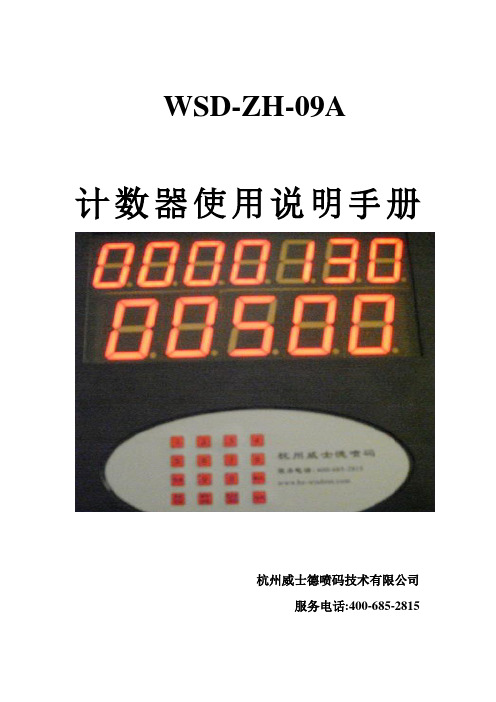
WSD-ZH-09A计数器使用说明手册杭州威士德喷码技术有限公司服务电话:400-685-2815杭州威士德喷码技术有限公司是专门经销和生产喷码设备和耗材的一家优秀企业,从事喷码行业多年,有着非常丰富的经验。
为了适应广大用户的生产需求,特为水泥行业开发WSD-ZH-09 型计数器,该计数器使用简单,计数准确,使用方便,可以用一台主机最多连接12个计数器窗口,可在不同的地方随时观察计数数值,子窗口链接距离1000米。
可减少人工计数人员的工作量,降低误差,以一个年产100万吨的水泥厂为例,0.5%的误差是(1000000吨*20包/吨*0.5%)=100000包,这样的误差对于水泥企业来说无疑是巨大的,还容易造成企业利益流失及客户信任度下降。
设备面板显示:上面7位数码管为计数总和,总计数为9999999,可自动循环计数。
下面一行为单次车装量,最大值为59999。
使用方法:开机显示:月份日期星期以及时间1.时间的设定:当时间不准确时请按累加数/时间键,机器将显示年二位。
月二位,日二位,星期一位,空一位,小时二位,分钟二位。
如:2009年2月27号星期五9:55分,将显示成:按正确的数字键将修改闪烁那位的数字并前进一位,如有错误可按取消键退格。
最后按确认修改保存,回到初时时间界面。
如不保存只能关电源。
2.计包学习:本产品可以适应任何长度、任何流水线速度的包装产品的计数,主要是通过计包学习来完成的,通过对水泥厂的流水线进行速度和包长的综合检测,当设备安装完成(即接近开关和红外感应检测都正常)后,先必须进行计包长度学习。
按清零/学习键,屏幕将出现表示第一次学习(按取消可退出),开动流水线,让包过红外对管,此时屏幕下行会出现一数字,如:07 08。
07表示接近开关的计数值,08表示光电开关的计数基值。
此数字表示一包在红外对管接收到信号时接近开关翻转次数,建议此数据要大于5小于16,按确认完成,这时候会出现表示第二学习,共学习四次,每次按确认完成。
光电计数器

AT89C51的工作电源电压为5(1±0.2)V且典型值为5V,最高工作频率为24MHz。
4.2 键盘输入电路及数码管LED显示当前键入数字电路
键盘是计算机最常用的输入设备,是实现人机对话的纽带。按其结构形式可分为非编码键盘和编码键盘。
编码键盘采用硬件方法产生键码。每按下一个键,键盘能自动生成键盘代码,键数较多,且具有去抖动功能。这种键盘使用方便,但硬件较复杂,PC机所用键盘即为编码键盘。非编码键盘仅提供按键开关工作状态,其键码由软件确定,这种键盘键数较少,硬件简单,广泛应用于各种单片机应用系统,本次试验使用的就是非编码键盘。
3.2 设计原理
1、系统利用红外LED发光管作为光源,光敏三极管接受计数脉冲,当光敏三极管未受到光照时,使光电管截止,其集电极输出高电平,光敏三极管受到光照时,使光电管导通,集电极变为低电平,如此便在光敏三极管的集电极产生一个负脉冲。若将此脉冲接在单片机定时器/计数器的输入端,便可以进行光电计数。
2、光电计数器的计数值通过单片机扩展的电路在LED显示器上11553
12级通信工程二班
指导老师王琼
2015年7月18日
一、课题概述
在许多实际生产过程中都要对事件进行计数,例如,通过传送带上的货物,生产流水线上的产品数量等均要进行自动计数,可见计数器在工业控制中有着广泛的应用。传统的数字计数器都是用中小规模数字集成电路构成的,不但电路复杂,成本高,功能修改也不易。用单片机制作的计数器可以克服传统数字电路计数器的局限,有着广阔的应用前景。
六、软件流程图
七、心得体会
通过这次光电计数器的设计,使我对单片机系统有了更深的了解。本设计只是一个简单的光电计数器,还可以有很多的附加功能。这次实验不仅使我对单片机的认识有了加深,也提高了自己的动手能力。我意识到实践的重要性,同时也学到了很多书本上学不到的知识。
LE-03电能计数器说明书

LE-03Electric energy meter,3-phaseThe LE-03 is a static (electronic) calibrated electricity meter of three-phase alternating current in a direct system.A special electronic system under the influence of flowing cu-rrent and applied voltage in each phase generates pulses pro-portional to the energy drawn in the respective phase. Energy consumption in the phase is indicated by a flashing of corre-sponding LED (L1, L2, L3). The sum of the three phase pulses is indicated by a flashing LED and converted into energy absorbed throughout the three-phase system. Its value is displayed by the mechanical drum abacus.The last, red number on the drum abacus indicates row 1/10 kWh (100 Wh).F&F Filipowski sp. j.Konstantynowska 79/81, 95-200 Pabianice, POLAND phone/fax (+48 42) 215 23 83 / (+48 42) 227 09 71Do not dispose of this device in the trash along with other waste! According to the Law on Waste, electro coming from households free of charge and can give any amount to up to that end point of collec� on, as well as to store the occasion of the purchase of new equipment (in accordance with the principle of old-for-new , regard-less of brand). Electro thrown in the trash or abandoned in nature, pose a threat to the environment and human health.Active energy consumed AE+ [kWh]The indicator has a pulse output. This allows you to connect a pulse meter-reading pulses generated by the counter. For proper operation of the indicator is not required to connect additional devices.The meter is marked with individual serial number allowing its unambiguous identification. The marking is laser engraved and cannot be removed).1. Disconnect the power supply.2. T he indicator mounted on a rail in the distribution box.3. U sing a screwdriver, remove the screws and remove the front shield meter terminals.4. C onnect power to terminals 1 (L1), 3 (L2), 5 (L3).5. N -wire connect to terminal 7.6. A dditional pulse receiver connected (optional) to terminals 9 (+) and 8 (–).Mounting1power input L1IN6power output L3OUT 2power output L1OUT7N-wire neutral3power input L2IN8pulse output (–)4power output L2OUT9pulse output (+)installation 4-wire rated voltage 3×230/400 V minimum measured current 0.04 A base current 10 A maximum current 100 A voltage measuring range 160÷265 V measurement accuracy (IEC62052) 1st class rated frequency 50 Hz insulation protection class II housing PC+ABS material own power consumption <10 VA; <2 W indication range 0÷999999.9 kWh constant 800 pulses/kWh current consumption signalling L1, L2, L3 phases 3× red LED read-out signalling red LED pulse outputtype open collector maximum voltage 27 V DC maximum current 27 mA pulse time 35÷80 ms* working temperature -20÷55°C terminal 25 mm² screw terminals dimensions 7 modules (122 mm) mounting on TH-35 rail ingress protection IP20 __________* depends on the current consumptionF&F products are covered by a 24-month warranty from the date of purchase. The warranty is only valid with proof of purchase. Contact your dealer or contact us directly.CE declarationF&F Filipowski sp. j. declares that the device is in conformity with the essential requirements of The Low Voltage Directive (LVD) 2014/35/EU and the Electromagnetic Compatibility (EMC) Directive 2014/30/UE.The CE Declaration of Conformity, along with the references to the standards in relation to which conformity is declared, can be found .pl on the product subpage.»Please read the instructions carefully before installation.»The device should be installed and operated by qualified per-sonnel who are familiar with its design, operation, and asso-ciated risks.»Do not install a meter that is damaged or incomplete.»The user is responsible for proper grounding of the system, proper selection, installation, and efficiency of other devices connected to the meter, including safety devices such as over-current, residual current and overvoltage circuit breakers.»Before connecting the power supply, make sure that all cables are connected correctly.»It is essential to observe the operating conditions of the meter (supply voltage, humidity, temperature).»To avoid electric shock or damage to the meter, turn off the power supply whenever the connection is changed.»Do not make any changes to the unit yourself. Doing so can result in damage to or improper operation of the device, which in turn can pose a threat to people operating it. In such cases, the manufacturer is not responsible for the resulting events and may refuse the provided warranty in the event of a complaint.»Do not tighten the terminals without the wire inserted. This may damage the lift mechanism of the terminal or the plastic cover of this terminal.。
ct4s-1p计数器说明书
ct4s-1p计数器说明书一.产品概述CT4S-1P计数器是一款高性能、可靠稳定的计数器,广泛应用于工业自动化领域。
其具有高精度计数、可编程设置、触摸屏操作等特点,可满足各种计数控制需求。
二.产品特点1.高精度计数:CT4S-1P计数器采用先进的技术和高质量的元器件,能够实现精确计数,最小计数单位可达0.0012.可编程设置:用户可以根据实际需要,自定义计数范围、警报设置、计数方式等参数,满足不同应用场景的需求。
3.触摸屏操作:CT4S-1P计数器配备了高灵敏度触摸屏,可以直观、便捷地进行设置和操作,大大提高了用户使用的便利性。
4.多种输入方式:支持多种输入方式,包括脉冲输入、光电开关输入、手动输入等,适应不同的计数控制需求。
5.易于安装:CT4S-1P计数器具有紧凑的外形设计和方便的安装孔位,可以轻松安装在各种设备中。
三.技术参数1.输入电压:AC110-240V2.输入信号:脉冲信号、开关信号3.输出信号:继电器输出、电平输出5.计数方式:正向计数、反向计数、累计计数6.计数精度:0.0017. 外观尺寸:128mm * 96mm * 65mm四.使用说明1.电源接入:将CT4S-1P计数器插头插入相应电源插座,确保输入电压符合产品要求。
2.输入信号接入:根据实际需求选择适当的输入信号接口,并将输入信号线连接到对应接口上。
3.参数设置:按下触摸屏上的设置按钮,进入设置界面,可以设置计数范围、警报值、计数方式等参数。
4.计数操作:按下启动按钮,计数器开始计数,触摸屏上的显示会随着计数的增加而变化。
可以通过停止按钮停止计数,或者通过清零按钮将计数器清零。
5.输出控制:可以根据需要选择输出方式,通过触摸屏上的设置按钮进入设置界面,选择继电器输出或电平输出,并设置相应的参数。
五.注意事项1.安装前请确保输入电压符合产品要求,接线正确可靠。
2.请避免计数器与强磁场、高温、湿度较大的环境直接接触。
3.在调整设置参数时,请确保机器停止工作,以免发生意外。
计数器说明书
计数器说明书计数器说明书简介计数器是一种常见的工具,用于记录和计算数量。
它可以用于各种场景,例如统计人数、记录器材使用次数、倒计时等。
本文将介绍计数器的使用方法、规格和注意事项。
使用方法计数器通常有以下几种基本操作:1. 初始化计数器在开始使用计数器之前,需要将计数器的初始值设定为所需的值。
可以通过编程语言的变量或者操作界面上的设置按钮来进行初始值的设定。
2. 计数增加通过增加计数器的值来记录数量的增加。
一般来说,可以通过点击计数器的加号按钮、调节旋钮或者编程语言的计数器加法操作来实现计数的增加。
可以根据实际需求选择合适的增加步长。
3. 计数减少通过减少计数器的值来记录数量的减少。
与计数增加类似,可以通过点击计数器的减号按钮、调节旋钮或者编程语言的计数器减法操作来实现计数的减少。
同样,可以根据实际需求选择合适的减少步长。
4. 显示计数值计数器通常会有一个显示面板,用于显示当前的计数值。
显示面板可以是一个数字显示屏、LED指示灯或者编程语言的输出窗口。
通过观察显示面板上的数值,可以了解当前的计数结果。
5. 重置计数器在某些场景下,需要清零计数器并重新开始计数。
可以通过点击计数器的重置按钮、调节旋钮或者编程语言的计数器赋初值操作来实现计数器的重置。
规格计数器通常具备以下规格:- 计数范围:不同的计数器具有不同的计数范围。
有些计数器的范围是固定的,例如0到9999,而有些计数器的范围可以根据需要进行设定。
- 步长:计数器的步长是指每次增加或减少的数量。
步长可以根据实际需求进行调整,一般可以是1,也可以是其他数字。
- 显示方式:计数器的显示方式可以根据实际需求进行选择。
常见的显示方式包括数字显示屏、LED指示灯等。
- 计数器类型:计数器可以分为模拟计数器和数字计数器两种类型。
模拟计数器通常通过旋钮进行操作,而数字计数器则通过按钮或者编程语言进行操作。
注意事项在使用计数器的过程中,需要注意以下几点:1. 避免超过计数范围:在使用计数器时,需要注意不要超过计数器的计数范围。
多功能光电计时器操作说明简表与使用说明书

多功能光電計時器操作說明簡表與使用說明書編寫者:國立清華大學物理系戴明鳳,日期:97.02.22圖A-1 多功能光電計時器一、儀器工作原理及特點使用精密的紅外線光電感應器所製作的光電閘,搭配高速微處理運算器測量運動體的運動時間、速率和加速度,具特定實驗模組化的測量功能。
本機採用國際流行的薄膜式按鍵開關面設計,並含微處理機單元及智能化的測量技術讀取、處理暨儲存數據。
以微秒級為時基的時間測量裝置,可提供精確位數高達五位元的時間測量,並具有存儲功能。
操作簡單,只需使用四個操作鍵即可完成各種不同的測量功能。
可作為計時器、計數器、信號源和6V直流穩壓電源使用。
本機除了具有一般計時器的功能外,並可用以測量運動物體的加速度、重力加速度、周期等物理量,可直接顯示物體的移動速率和加速度值。
經常運用在大學院校普物實驗課程中有關運動的實驗中,如與氣墊導軌、斜槽軌道、自由落體和碰撞等各種運動實驗系統的儀器配合使用。
二、儀器規格(1)以美國INTEL公司的MCS-51數位微處理單元(CPU)為自動測量及數據處理的主控系統。
(2)採用12MHz的石英晶體振盪器最為時基單元,時基精度為2 MHz ±20 Hz (10 ppm)。
(3)使用0.56〞高亮度的LED數碼顯示裝置,具有五位元的顯示單元,分別為四個LED單位顯示和八個LED功能指示。
(4)溢出指示“0.0.0.0.”。
(5)含小數點和單位顯示,具有量程自動定位、自動換檔及自動進行四捨五入的智能化數據處理功能。
(6)各項物理量的測量範圍(a)速度範圍為:0.00~1000.0 cm/s(b)加速度範圍為:±0.00~1200.0 cm/s2(c)計數範圍為:0~99999(d)計時範圍為:0.00 ms~999.99 s(e)0.01 ms數量級以上確保五位有效數字顯示。
(7)可存儲20個時間數據,在周期測量中存儲21個時間數據(前20個振動周期和一個n次(最多9999周期)振動的累加時間總和。
- 1、下载文档前请自行甄别文档内容的完整性,平台不提供额外的编辑、内容补充、找答案等附加服务。
- 2、"仅部分预览"的文档,不可在线预览部分如存在完整性等问题,可反馈申请退款(可完整预览的文档不适用该条件!)。
- 3、如文档侵犯您的权益,请联系客服反馈,我们会尽快为您处理(人工客服工作时间:9:00-18:30)。
光控计数器使用说明书
一.系统组成及工作原理
1.1 系统组成
整个系统由五个部分组成:光控电路、触发脉冲、加减计数、显示译码和数码显示,其工作原理框图如下:
1.2 工作原理
首先由光控电路将接收的光信号转换为电信号,经施密特触发器整形触发脉冲,输出计数脉冲信号。
再通过计数器和译码器,在LED数码显示管上显示数目的增加或减少,实现自动计数的功能。
二.使用说明
设计上下两路光控电路,模拟当人进入或走出房间时,先后触发两路光控电路产生脉冲信号。
先挡住上路中的红外线发射二极管,再挡住下路中的发射二极管,LED数码管上显示数目增加;反之,先挡下路二极管,再挡上路,LED数码管上显示数目减少。
三.电路图
5V。