Set 7240 - Fire Station
富士通文件扫描仪FI-7240说明书

The essential fi Series scanner with exceptional business performance.40Pages per minute DuplexScans bothsidesSizes up toLegal8.5” x 14” max.ScansPlastic CardsFlat andembossed600Optical DPI24-bit ColorAcceptsSticky NotesTapedReceiptsLabelsTWAIN& ISIS®SupportedProfessional workgroupdocument scannerTechnical Specifi cationsDocument feeding methodsAutomatic Document Feeder (ADF)FlatbedScanning modes Simplex/Duplex in Color, Grayscale, or MonochromeImage sensor type Color Charge-Coupled Device (CCD) x 3(Front x 1, Back x 1, Flatbed x 1)Light source White LED Array x 3 (Front x 1, Back x 1, Flatbed x 1)Multi-feed protection Ultrasonic multi-feed detection sensorPaper detection sensorPaper protectionLag detection Document sizeMinimum2.0” x 2.13” (50.8 x 54 mm)Maximum8.5” x 14” (216 x 355.6 mm)Long page scanning 18.5” x 220” (216 x 5,588 mm)Flatbed maximum8.5” x 11.7” (216 x 297 mm)Paper weightPaper 7.2 to 110 lb (27 to 413 g/m 2)Plastic cardUp to 1.4mm 2Scanning speed 3200 or 300 dpi, Letter, Color 4, Grayscale 4and Monochrome 5ADF, Simplex 40 pages/minute ADF, Duplex 80 images/minute Flatbed1.7 seconds (200 dpi)ADF capacity 680 Sheets (A4/Letter: 20 lb. or 80 g/m 2)Background colors ADF: White / Black (switchable)Flatbed: White (Black optional, sold separately)Output resolution 7Color (24-bit), Grayscale (8-bit), Monochrome (1-bit)50 to 600 dpi, 600 dpi optical, 1200 dpi software 8InterfaceUSB 2.0 / USB 1.1Power requirements 100 to 240 VAC, 50/60 Hz Power consumption Operating: 39 W or less Sleep mode: 1.8 W or lessAuto-standby (Off) mode: 0.35 W or lessOperating environmentTemperature 41° to 95°F (5° to 35°C)Relative humidity 20% to 80% (non-condensing) Dimensions (WxDxH) 911.8” x 22.7” x 9.2” (300 x 577 x 234 mm)Weight19.4 lb (8.8 kg)Included in the boxADF paper chute, AC cable & adapter,USB cable, Setup DVD-ROM Bundled software (DVD format)PaperStream IP (TWAIN/ISIS) Driver, WIA Driver 12,PaperStream Capture, ABBYY FineReader for ScanS-nap 10, Scanner Central Admin, Software OperationPanel, Error Recovery GuideEnvironmental designations 11ENERGY STAR®, RoHS, and EPEAT Silver Supported operating systemsWindows® 10 (32-bit/64-bit), Windows® 8.1 (32-bit/64-bit), Windows® 7 (32-bit/64-bit), Windows Server® 2019 (64-bit),Windows Server® 2016 (64-bit),Windows Server® 2012 R2 (64-bit),Windows Server® 2012 (64-bit), Windows Server® 2008 R2 (64-bit), Windows Server® 2008 (32-bit/64-bit)Linux (Ubuntu)12Image processing functionsMulti-image output, Auto color detection, Blank page detection, Dynamic threshold (iDTC), Advanced DTC, SDTC, Error diffusion, Dither, De-screen, Emphasis, Dropout color, sRGB output, Hole punch removal, Index tab cropping, Split image, De-skew, Edge fi ller, Vertical streak reduction, Cropping, Static threshold,Moire removal1 Can scan documents longer than A4 sheets. Documents longer than 34” require using lower resolution (200DPI or less) 2 Can scan up to 3 flat plastic cards or one embossed card at a time 3 Actual scanning speeds are affected by data transmission and software processing times 4 Using JPEG compression 5 Using TIFF CCITT Group 4 compression 6 Maximum capacity varies depending upon paper thickness 7 Selectable maximum density may vary depending on length of document 8 When scanning at high resolutions (600 dpi or higher), some limitations to document size may apply depending on system environment 9 Dimensions measured with machine closed to minimum positions. During operation, machine depth is increased by the ADF chute and output tray 10 Can be downloaded following instructions on Setup DVD-ROM 11 PFU Limited, a Fujitsu company, hasdetermined that this product meets the ENERGY STAR ® guidelines for energy efficiency and RoHS requirements (2005/95/EC) 12 Functions equivalent to those offered by PaperStream IP may not be available with the ImageScanner Driver for Linux and WIA DriverFujitsu Computer Products of America, Inc.1250 East Arques Avenue, Sunnyvale, CA 94085888.425.8228 Sales · 800.626.4686 Technical Support /fcpa·*****************.comThe essential business scanner▪Scans documents at up to 40 pages / 80 images per minute ▪Large-capacity 80-page Automatic Document Feeder ▪Letter-sized fl atbed for delicate and bound documents ▪Supports plastic and embossed cards ▪Scans long documents up to 220”Smart features to enable your workfl ow▪Scan documents of mixed paper sizes and weights all at once—no need to pre-sort ▪Doesn’t slow down when scanning in color at 300dpi▪Intelligent MultiFeed Function allows easy manual bypass for sticky notes, taped receipts, andlabels that can slow down batch scanning▪Ultrasonic Double Feed Detection identifi es sheets stuck together so you don’t miss an image ▪Skew Reduction signifi cantly improves feeding performance and ensures that your wholedocument gets accurately captured from edge to edge Clean up and optimize scans without changing settings in advancePaperStream IP (PSIP) is a TWAIN/ISIS ®-compliant driver with easy-to-use features including:▪Assisted Scanning lets you choose the best image cleanup through visual selection▪Advanced Image Cleanup corrects the toughest documents, including colored and decoratedbackgrounds, to improve OCR and reduce rescans▪Auto Color Detection identifi es the best color mode for the document ▪Blank Page Detection removes blank pages automatically▪Front and Back Merge places two sides of a page into one convenient imagePaperStream Capture makes scanning fast and easyEliminate the learning curve. PaperStream Capture’s user-friendly interface allows easy operation from start to fi nish. Changing scan settings is simple. Indexing and sorting features include barcode, patch code, and blank page separation —making batch scanning a breeze for operators.Centralized fl eet managementIncludes Scanner Central Admin Agent to remotely manage your entire fi Series fl eet. Effectively allocate your resources based on scan volume, consumables wear, and more.Make it even better with PaperStream Capture Pro Optional PaperStream Capture Pro software offerssuperior front-end capture, image processing, and options for enhanced data extraction and indexing for release.Popular Consumables and OptionsBrake Roller PA03670-0001Replace every 200,000 sheets or 1 year Pick Roller PA03670-0002Replace every 200,000 sheets or 1 yearBlack Flatbed Pad PA03670-D801Black fl atbed background pad PaperStream Capture ProPA43404-A665PaperStream Capture Pro workgroup licenseVisit to buy Genuine Fuijtsu Parts and Consumables©2019 Fujitsu Computer Products of America, Inc. All rights reserved. Microsoft, SharePoint, and Windows are trademarks of Microsoft Corporation. ISIS is a registered trademark of EMC Corporation. ABBYY , FineReader are trademarks of ABBYY Software Ltd. ENERGY STAR is a U.S. registered trademark. PaperStream is registered trademark of PFU Limited. All other trademarks are the property of their respective owners. Specifi cations subject to change without notice. Printed in USA on paper from responsible sources. Please recycle. 190331R1♼Insist on Genuine Fujitsu Service to keep your scanner running at its best. Ask your reseller or call 888.425.8228.。
微芯科技-家用独立式红外烟雾报警器控制方案

微芯科技:家用独立式红外烟雾报警器控制方案
众所周知,在中国,如办公、宾馆、商业和娱乐等公共场所,都必须要求安装烟雾报警器及消防设施;而在如公寓、别墅和宿舍等民用场所则没有强制要求。
但是,在欧美发达国家,居民的消防意识比较强,通常住宅中也会安装烟雾报警器,报警器的探头一般采用独立式,其工作原理与我们常见的集控式探头非常类似,也是由红外或者离子传感器、电子控制单元以及蜂鸣器组成,不同的是由单独的电池供电。
目前,很多独立式烟雾报警器通常由9V电池供电。
然而,9V电池
的成本较高且实际使用寿命较短,用户可能每隔3~4年就必须更换电池,这样不仅给日常的使用带来不便,同时也增加了客户的使用成本。
此外,现有的解决方案通常采用硬件校准,电路相对复杂,生产效率低。
鉴于这样的原因,Microchip(美国微芯科技公司)近期推出了一款可以工作在3V系统中,可软件编程校准的专用芯片RE46C190。
RE46C190是专用于光电式烟雾报警器的集成芯片,它具有工作电压低、功耗低和外围电路简单等特点。
图1是典型的应用电路。
研控科技 YKD2405PR 总线型步进驱动器 用户手册说明书
目录前言 (1)1概述 (2)1.1产品介绍 (2)1.2特性 (2)1.3应用领域 (2)1.4产品命名规则 (3)2性能指标 (4)2.1电气特性 (4)2.2使用环境 (4)3安装 (5)3.1安装尺寸 (5)3.2安装方法 (5)4 驱动器端口与接线 (6)4.1接线示意图 (6)4.2端口定义 (7)4.2.1状态指示灯 (7)4.2.2控制信号输入/输出端口 (7)4.2.3电源输入/电机输出端口 (8)4.2.4拨码开关 (8)4.2.5 MODBUS总线端口 (8)4.3输入/输出端口操作 (8)4.4拨码开关设定 (10)4.5 RS485通讯端口 (12)5适配电机 (13)5.1电机尺寸 (13)5.2技术参数 (13)5.3电机接线图 (14)6 MODBUS通讯协议 (15)6.1 MODBUS寄存器地址定义 (15)6.2 MODBUS常用功能码 (21)6.2.1读保持寄存器命令03 (21)6.2.2写单个寄存器命令06 (22)6.2.3写多个寄存器命令16 (22)6.2.4通讯错误码 (23)6.2.5应用示例 (24)7运动控制功能介绍 (26)7.1位置模式 (26)7.2速度模式 (27)7.3多段位置模式 (27)7.3.1 位置段参数介绍 (27)7.3.2 多段位控制方式 (28)7.4多段速度模式 (29)7.4.1 速度段参数介绍 (29)7.4.2 多段速度控制方式 (29)7.5回原点功能 (30)7.6运动控制命令 (31)7.6.1 启动命令(0x0027) (31)7.6.2 停止命令(0x0028) (31)7.6.3 回原点命令(0x0030) (32)8报警排除 (33)9版本修订历史 (34)10保修及售后服务 (35)10.1保修 (35)10.2售后服务 (35)前言感谢您使用本公司总线型步进驱动器。
在使用本产品前,请务必仔细阅读本手册,了解必要的安全信息、注意事项以及操作方法等。
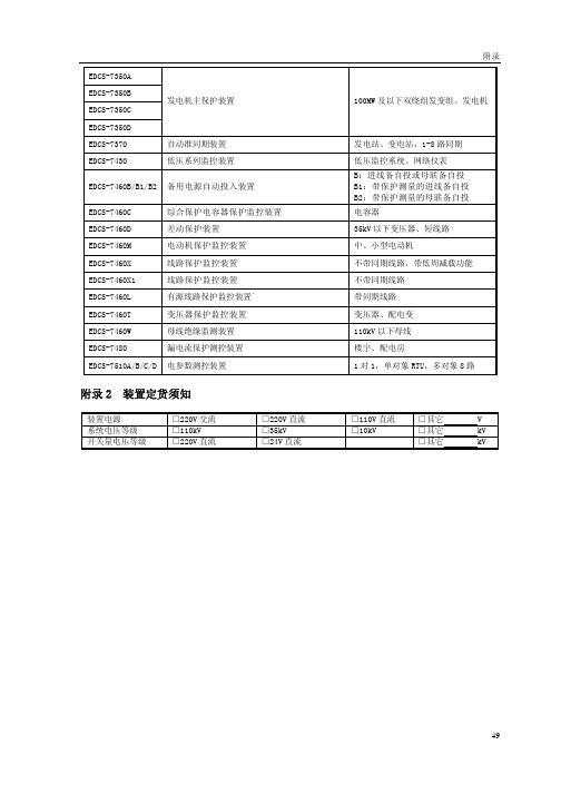
EDCS-7240 _4U25与6U20_使用说明书2.00(07.11.14)
CANL 2
G00 3
G00
G00
图 2-1 CAN 通讯连接示意图
R G00
注: a.在一个系统的整个 CAN 通讯网中,装置端只能装接 1 只 120Ω的电阻。因为通讯总线加匹 配电阻可以使其成为回路,有效防止通讯总线上产生自激振荡,而影响通讯效果。 b.通讯网络中的屏蔽地 G00 应与计算机的屏蔽地相接。 c.上图接线是以 PCL-841CAN 总线通信卡为例。
实际应用中 RS-485 组网有多种拓扑结构,以下图 2-2 以 RS-422/485 通信卡(PCL-745)为例。 线形连接,就是从上位机开始自近及远将多台 EDCS-7000 系列装置一个接一个连入网络,这 种连接方式适合装置装置较为集中,未来又有扩展需要的场合。如图 2-2 所示。 图中 Rt 为防反射电阻。反射电阻值的大小必须与所用电缆的阻抗相匹配。
35kV 及以下双绕组变压器
电容器 厂用电 大、中型异步电动机 大、中型同步电动机 110kV 及以下线路,具有距离保护(最 短可保护 1 公里)、高频保护、录波功 能。 110kV 及以下线路,带 11 次谐波监视 及低周低压解列。 110kV 三绕组变压器 110kV 三绕组变压器(最大四侧) 110kV 三绕组变压器(最大五侧) 需要非电量保护的场合 110kV 变压器后备保护、测控 110kV 及以下单母线、单母线分段、 双母线、双母线四分段,且带旁母运 行的主接线型式。 100MW 及以上发变组、发电机 100MW 及以上发变组、发电机 200MW 及以下发变组、发电机
110kV 线路保护装置
EDCS-7220 EDCS-7230A EDCS-7230B EDCS-7230G EDCS-7230F EDCS-7240
硬件模块单元测试报告-模板

硬件模块单元测试报告编制: 日期:审核: 日期: 批准: 日期:目录目录 (1)第一章概述 (3)1.1目的和范围 (3)1.2测试概述 (3)第二章测试资源及环境 (4)2.1 硬件配置 (4)2.2 测试设备清单 (4)2.3 测试环境 (4)2.4 测试方式 (4)第三章测试数据 (6)3.1 主控板测试 (6)3.1.1短路测试 (6)3.1.2直流电压、纹波测试 (6)3.1.3接口通讯信号测试 (8)3.1.3.1主控板与按键板打印部分 (8)3.1.3.2主控板与核心板 (8)3.1.3.3主控板与液晶屏 (8)3.1.3.4主控板与触摸屏 (9)3.1.3.5主控板与感光板 (10)3.1.3.6主控板对按键板指示灯部分检测信号 (10)3.1.3.8主控板与WIFI板 (10)3.1.4充电测试 (11)3.1.5电源转换效率测试 (11)3.1.5.1 5V电源转换效率测试 (11)2.1.5.2 +8V电源转换效率测试 (13)3.1.6 DC_DC带负载测试 (14)3.2 按键板测试 (15)3.2.1短路测试 (15)3.2.2直流电压、纹波测试 (15)3.2.3接口通讯信号测试 (15)3.2.3.1 按键板与打印机 (15)第一章概述1.1目的和范围本文描述H3硬件模块的测试方法和步骤, 本方案的来源是《H3硬件总体需求》和《H3硬件总体方案》适用范围是:1.2测试概述在硬件模块测试阶段, 测试人员根据细化后的方案进行集成测试, 测试的重点是接口, 主要包括以下几个方面:1.各个板卡接口和测试点电压纹波测试2.控制/检测信号逻辑状态分析第二章测试资源及环境2.1 硬件配置2.3 测试环境环境温度: 0-55℃;大气压力: 700hPa~1060hPa;相对湿度:15% ~ 95%, 非凝2.4 测试方式内部测试第三章测试数据3.1 主控板测试3.1.1短路测试3.1.3接口通讯信号测试3.1.3.1主控板与按键板打印部分3.1.3.2主控板与核心板3.1.3.3主控板与液晶屏3.1.3.4主控板与触摸屏3.1.3.5主控板与感光板3.1.3.8主控板与WIFI板3.1.4充电测试使用电源交流100~240Vac 50Hz/60Hz 使用内置锂电池 12.6V/2600mA3.1.6 DC_DC带负载测试3.2 按键板测试3.2.1短路测试3.2.3接口通讯信号测试3.2.3.1 按键板与打印机。
菜维尔火警系统MF200 400用户手册说明书
PLEASE PASS THIS BOOKLET TO THE USER,AFTER INSTALLATION KEEP WITH PANEL.MENVIER FIRE SYSTEM MF200/400 MF200-72/400-72For serviceTel:please call:Service agreement numberCooper Lighting and Security Ltd.Wheatley Hall Road, Doncaster, South Yorkshire, DN2 4NB, United Kingdom SalesGeneralExportTel:+44 (0)1302 - 303303+44 (0)1302 - 321541 +44 (0)1302 - 303250CONTENTSSERVICE SUPPORT NUMBER (1)SYSTEM INFORMATION (2)PANEL CONTROLS AND INDICATORS (3)PANEL OPERATION (4)GENERAL (4)NORMAL OPERATION (4)SUPERVISOR MODE (4)PANEL INTERFACE CONNECTIONS AND PANEL CONTROLS (6)INPUTS (6)OUTPUTS (6)FIRE CONDITION (6)WIRING DIAGRAMS (7)INSTALLATION INSTRUCTIONS (8)GENERAL (8)ADDITIONAL NOTES ON INSTALLATION FOR ELECTROMAGNETICCOMPATIBILITY(EMC) (8)INSTALLING THE PANEL (9)ROUTINE TESTING (9)FAULTS (10)FUSES (10)TECHNICAL SPECIFICATION (11)FIRE ALARM SYSTEM LOG MASTER SHEET (12)Zone No. of Call No. of Smoke No. of Heat LocationNo Points Detectors Detectors123*4*TOTAL ALARM LOAD CurrentNo of Sounders, BellsElectronicOtherDetails of system expansion:* MF400 only THIS SYSTEM HAS BEEN INSTALLED IN ACCORDANCE WITH THEREQUIREMENTS OF ..................................................STANDARDSIGNED ..................................................................... DATE .............................. FOR...........................................................................................................................THIS SYSTEM HAS BEEN COMMISSIONED IN ACCORDANCE WITH THEREQUIREMENTS OF ..................................................STANDARDSIGNED ..................................................................... DATE .............................. FOR...........................................................................................................................AudiblePiezo buzzer integral within panel, common to fire and fault.KeysThe controls of the panel are via a 5 key keyboard on the front of the panel.A key press is acknowledged by a vlip of the internal panel buzzer and in the normal mode the Supervisor Mode LED will flash.Keys labelled 1, 2 and 3 have more than one function these are described below.KEY Normal Operation Supervisor Mode Primary function Secondary function Tertiary function1Code Entry Toggle for Supervisor Mode Toggle for Supervisor Mode Disable Mode and Test Mode Disable Mode and Test Mode 2Code Entry Silence/Re-Sound Alarms Select Function-Disable or Test 3Code Entry Lamp Test/Exit (Toggle through Functions)Disable or Test 4NONERESETRESETPANEL CONTROLS AND INDICATORS Note Zones 3 & 4are not providedon MF200VisualPANEL OPERATIONGeneralThe panel has 2 levels of operation. Normal Mode and Supervisor Mode.Normal OperationSilence Buzzer (key 5)The user can silence the PANEL buzzer by pressing the 'SILENCE BUZZER' key (at any time), the buzzer will then give a beep approximately every 10 seconds.Note:-This does not silence the alarms only the panel buzzer.Supervisor Mode Entry (key 1, key 2, key 3)By entering a 4 digit access code the user will enter the Supervisor Mode. The access code is 2113. By pressing the keys in the correct order the user will see the Supervisor LED flash indicating the panel is in Supervisor Mode.Supervisor Mode Operation -Enter supervisor mode using access code 2113 prior to carrying out any of the following operations.Auto time-out of supervisor mode will occur 2 minutes after last action.RESET(key 4)Pressing 'RESET' at any time while in Supervisor Mode will reset the panel, clearing any fire, fault or Test Mode information. If a fire or fault exists the panel will re-enter the fire condition.Note:-Operating RESET will not clear disable information.Lamp Test/Exit supervisor Mode (key 3)While the supervisor LED is flashing the user can perform a lamp and buzzer test. All LED's will light and the buzzer will sound. This also exits the Supervisor Mode.Silence/Sound Alarms (key 2)While the Supervisor LED is flashing pressing 'SOUND/SILENCE' will silence or sound the alarms. If a fire is detected on another zone the alarms will re-sound.Note:-If the alarms are silenced and fire condition exists the panel buzzer will sound continuously. Disable Mode (key 1, key 2, key 3)The panel allows the supervisor to disable individual zones, both alarm lines together or the remote signal output. When any of these functions are disabled the buzzer will beep.Zones, when disabled will not be monitored for fires or faults.Alarms, when disabled will not be monitored for faults, or be activated by a fire condition.Remote signal, when disabled will not be activated by a fire condition.To disable/re-enable any of the above functions the following procedure should be followed:-1.Press 'key 1' to toggle the flashing LED from 'Supervisor Mode' to 'Disable Mode'.PANEL OPERATION - continued2.Release and repress (key 3) to toggle through LED's representing each function.3.When you highlight the LED representing each function to be enabled/disabled press'key select’to enable/disable this function.4.To exit Disable Mode and leave the panel in the disable state press 'key 1' to toggle to SupervisorMode LED and press ‘key 3’or ‘key 4’5.When a function is disabled the LED corresponding to that function will remain lit even when youexit the Disable Mode.6.To reset from Disable Mode to Normal operation, press ‘keys 2-1-1-3’, repress ‘key 3’to togglethrough LEDs to required Zone, press ‘key 2’Disable Mode LED flashing. This will extinguish in 2 minutes.Test Mode (key 1, key 2, key 3)The panel allows the supervisor to test each zone individually or any combination of zones.When a zone is put into Test Mode the buzzer will beep.Remote signal will not operate when a fire signal is received from a zone in the test mode.The operation of zones which are not in the test mode will function as normal.A fire signal from a zone in test will cause the alarms to operate for a few seconds only.To put a zone into Test Mode, the following procedure should be used:-.1.Press 'key 1' to toggle the flashing LED from 'Supervisor Mode' to 'Disable Mode' to 'Test Mode'.2.Release and repress ‘key 3’to toggle through LED's representing each zone.3.When you highlight the LED corresponding to the zone to be put into Test / taken out of Testpress 'SELECT' (key 2) to select that zone. (Zone LED lit, Test LED flashing)4.Each manual call point and detector on the zone in test can now be tested.5.When a manual call point or detector is put into a fire condition on the zone in test, the alarmswill activate for approximately 2 seconds and the zone will remain in the fire condition forapproximately 10 seconds. The panel will then automatically reset the zones, which will take approximately 10 seconds. The panel will indicate a fire signal from a zone in test by turning on the corresponding zone fire LED.6.To clear all zone fire LED's press ‘key 3’.7.To exit Test Mode and leave the panel in the test state press 'key 1' to toggle to Supervisor ModeLED and press 'Lamp Test/EXIT(key 3) or press 'RESET' (key4). Zone LED lit, Test LED lit.8.To reset from Test Mode to Normal operation, press ‘keys 2-1-1-3’, ‘key 1-1’(i.e. twice). Repress‘key 3’to toggle through LEDs to required zone, press ‘key 2’Test Mode LED flashing. This will extinguish in 2 minutes.Note:-Alarms cannot be put into test modeIf a manual call point or detector is left in a fire condition on a zone in test, the panel will carry out step 5 until the fire signal is cleared.Operating 'RESET' will not clear test information. Test information is only lost when the mains supply and battery are disconnected or the function is re-enabled.PANEL INTERFACE CONNECTIONS AND INTERFACE CONTROLSInputsClass ChangeA pair of terminals are provided for class change. By shorting these terminals together (e.g. switch, time clock) the alarms will sound. The panel will not indicate a fire. The alarms will cancel when the short circuit is removed. If the short circuit is not removed the Alarms will NOT cancel.WARNING:- NO VOLTAGE SHOULD BE APPLIED TO THIS INPUT.ZonesMF400 provides 4 zones & MF200 provides 2 zones . The maximum number of detectors per zone line is 20 and end of line resistors must be fitted for correct operation.Manual call points used in the system are polarised. Use the connection details accompanying the call points to ensure the correct polarity is used, using the terminal marked '9300'.Detectors used in the system are polarised 24V Menvier detectors. They must be wired in accordance with instructions accompanying the detector. Use the terminal marked '9300'.OutputsAuxiliary DC OutputA24Vdc output is provided. This output is protected by a fuse which is monitored for rupture. This output can be to used to power fire or fault auxiliary equipment. Equipment must be connect to this output so that current will only be drawn from this output when a fire condition exists or when no fault exists.WARNING:-DO NOT EXCEED THE RATED OUTPUT CURRENTAuxiliary Fault OutputThis is a 'solid state' semiconductor switch which is normally operated with no fault present and de-activates when the panel detects a fault. It operates by providing 24Vdc which can be connected directly to a 24V auxiliary device (e.g. relay) and a pull down switch to 0V. It is current limited to10mA.Remote Signal Output (Auxiliary Fire Output)This is a 'solid state' semiconductor switch which operates when the panel detects a fire. It operates by providing 24Vdc which can be connected directly to a 24V auxiliary device (e.g. relay) and a pull down switch to 0V. It is current limited to 10mA. 'Class Change' and 'Sound/Silence' do not operate this output.AlarmsAlarm outputs are provided. ONLY polarised and suppressed equipment should be used.Ensure the polarity of the connections are observed at all times and end of line resistors are fitted for correct operation.The maximum alarm load is specified in the Technical Specification section.Alarm devices should be spread equally across the 2 alarm circuits.WARNING:-DO NOT EXCEED THE RATED OUTPUT CURRENT.Options included within this panel which are not required by EN54 are, Class Change, Remote Signal Output and Auxiliary DC output. These options cannot be used to simulate options with requirements within EN54.FIRE CONDITIONIf the panel receives a fire signal from a manual call point or detector the red fire LED will light, the panel buzzer will sound, the alarm devices will be activated and the remote signal will also activate. The red zone fire LED will light corresponding to the zone in fire. Any new zone in a fire condition will light.WIRING DIAGRAMS22K O h mA U X F A U L T A N D R E M O T E S I G N A L C O N N E C T I O N SINSTALLATION INSTRUCTIONSGeneralAll cables entering the panel must be via the cable entries provided or the aperture in the rear face. All cables must be tested for earth fault before connecting to the panel. Do not use a High Voltage Tester (Megger) on any cable after connection to any equipment including the panel.The wiring of each zone, interface control or alarm line should be in a 2 core cable.The total cable resistance for each zone must not exceed 85ohm.Any voltage drop on alarm line cables will affect the sound level of alarm devices and should be kept to a minimum.The Cable used for alarm devices must be of a type suitable for protection against fire for at least 30 minutes. The Extra Low voltage unscreened cables must be segregated from the mains cables. Please refer to BS 5839 part 1 1988 for more details.For zones and alarms the end of line resistor must be fitted to the end of the circuit. No 'spurs' shall be used.If a zone is not to be used the end of line resistor should be fitted in the corresponding zone terminal block between '+' and '-'.A cable screen termination for each panel interface is provided. The cable screen of any zone, interface control or alarm line should be connected directly to the corresponding terminal marked 'E'. Additional Notes On Installation For Electromagnetic Compatibility (EMC)When used as intended this product complies with EMC Directive (89/336/EEC) and the UK EMC regulations 1992 (SI 2372/1992) by meeting the limits set by the standards EN61000-3-2 1994,EN50081-1 1992 and EN50130-4 1996. The following installation guidelines must be followed:1. External cables must be connected using the cable entries or knockouts provided.2. When routing external cables inside the product they must bea) kept as short as possible.b) routed close to the metal back box.c) kept as far as possible from the electronics.Any modifications other than those in the main installation leaflet, or any other use of the product may cause interference & is the responsibility of the user, who should ensure compliance with the EMC & low Voltage directives.BatteryconnectionsInstalling the PanelRead all the installation instructions before commencing with the installation.Installation of this panel must be done by a suitably qualified/trained person. The installation must comply with IEE wiring regulations and with BS5839 part 1 1988.The electronic components within the Fire Panel are Static Sensitive. Do not touch the electronic components directly.1.Remove the front cover.2.Fix the metal back box to the wall using the 3 fixing holes. No 8 screws (or similar size) arerecommended.3.Interface cables may be connected into the panel either via the back cable entry slot or throughthe top cable entries, fit the plastic blanking plugs to any unused holes.4.The mains supply should be exclusive to the panel and double pole isolating switch should beprovided and clearly labeled 'FIRE SYSTEM- DO NOT SWITCH OFF.' (See BS5839 part 1 1988) Mains cable should only enter the panel via the top or bottom left cable entries.5.Connect the mains cable to the Mains input terminal block. Connect Earth to the terminal marked(E), Neutral to the terminal marked (N) and Live to the terminal marked (L). DO NOT TURN ON THE MAINS SUPPLY TO THE PANEL.6.Connect the battery connectors to the battery. Connect the RED wire to the battery terminalmarked RED (+). Connect the BLACK wire to the battery terminal marked BLACK (-). Ensure the wires are routed away from the switches.7.When power is first supplied, the Panel Buzzer will sound and all the LED Indicators will light forapproximately 2 seconds. Only the green power LED should be ON. After a few seconds the Fault and Power fault LED's will flash and the buzzer will beep to indicate no mains is present on the panel. (Other fault Indicators may be flashing at this stage). If the System Fault LED is lit and the buzzer is on continuously, remove the (+) battery connection and follow step (6) again.8.Connect the front cover to the panel by locating the bottom clips in their slots and fixing the anti-tamper screw located on top of the panel. CAUTION ELECTRIC SHOCK HAZARD :- BEFORE TURNING ON THE MAINS SUPPLY THE PANEL COVER MUST BE FITTED.9.Turn on the mains supply to the panel. The Power fault Indication should stop after a fewseconds.10.Carry out testing of the system.11.Manual call points should be individually tested for correct operation.12.Each detector should be tested.13.If any Auxiliary outputs are used or the Class Change input is used these should also be testedfor correct operation.14.Check all alarm devices work correctly.15.Details of the Fire Alarm installation should be made in this Instruction Booklet (page 2).16.Fill in the zone Identification Label and display clearly on or next to the panel.17. Pass all the documentation over to the end user.Maintenance should be carried out at regular intervals. Daily, Weekly, Quarterly and Yearly tests should be carried out. Detailed below is a summary of the Daily and Weekly tests. For full details of all the tests please refer to BS5839 Part 1 1988.Daily attention by the user•The panel indicates normal operation. If a fault is displayed it should be recorded in the log bookand reported to the service organisation.•That any faults from the previous day have received attention.Weekly attention by the user•At least one detector or call point per week is operated for correct operation, choosing a differentzone each week. The Panel should register this fire signal and the alarms and any ancillary equipment should operate•The Panel indication should be checked by pressing 'Lamptest/Exit'(key3) while in thesupervisor mode.•Any defects should be recorded in the log book and corrective action taken as soon as possible.INSTALLATION INSTRUCTIONS - continuedROUTINE TESTINGFAULTSGeneralAll fault conditions on the fire panel will be indicated by the 'FAULT' LED flashing, the panel buzzer beeping and at least one other fault specific LED flashing. The auxiliary fault output will de-activate. All faults indications will be cleared automatically if the fault is removed unless stated.CAUTION ELECTRIC SHOCK HAZARD :- BEFORE REMOVING THE PANEL COVER THE MAINS SUPPLY MUST BE TURNED OFF.Specific Fault Indication Fault/ActionPower Fault LED Flashing The 240V Mains supply, battery standby supply, battery charger andall the fuses are monitored for faults.Check the battery is connected to the charger correctly. Check theMains supply is switched on. Check the fuses for rupturesPower LED Flashing The Fire Panel internal power supplies are monitored for faults.Check 240V Mains supply is turned on. Check the fuses for ruptures.If the problem persists contact your service company.Zone(s) Fault LED Flashing The zone lines are monitored for open circuit, short circuit anddetector removed.Check the wiring for open circuits and short circuits. All detectors inthe system must be correctly fitted to the detector bases. Ensure theend of line resistors are correctly connected. If all the zone faultLED's are lit pressing 'RESET' whilst in the Supervisor Mode willclear this fault Indication.Alarm Fault LED Flashing This fault should be investigated immediately as it should beassumed the alarms are not operational. Each alarm line is monitoredfor open circuit and short circuit. The alarm line fuses are alsomonitored for ruptures. Exceeding rated Alarm and Aux DC load maycause internal power faults. If the Alarm lines switch off shortly afteroperation check for alarm line over-load. Press 'RESET' whilst inSupervisor mode to clear the fault indication.Check the wiring for open circuits and short circuits Ensure the end ofline resistors are correctly connected. Check the fuses for ruptures. Earth Fault LED Flashing The Fire Panel will indicate an earth fault if any connection to earthexists in any wiring connected to the panel, other than the Mainssupply Safety Earth. This could be caused if the any wiring insulationis broken, or ancillary equipment connected to the panel has a nonsafety earth connection. If the fault persists contact your servicecompany.System Fault LED on The Micro controller has a supervisor circuit monitoring it for correctoperation and has detected either a software or hardware fault. Toclear this fault indication press 'RESET' whilst in the SupervisorMode. If this fault persists contact your service company.Alarm 1 (1A 250V)Aux DC (250mA 250V) Alarm 2 (1A 250V)Note.All fuses are glass20mm quick blowBattery (5A 250V)TECHNICAL SPECStandards Design to comply with EN54 Part 4 1996 and Part 21996Electromagnetic Compatibility EN 50130-4 1996Alarm Systems Part 4 EN50081-1 1992EN61000-2-2-1994Number of Zones4(MF400) 2(MF200)Number of alarm Lines2Mains Input Voltage240Vac +10%-15%Standby Duration24HrSystem operating Voltage24Vdc NominalIndicatorsFire High intensity red Light Emitting Indicators (LED)Fault High intensity yellow LED'sPower High intensity green LEDFault IndicationsZones Open and short circuit, detector removedAlarms Open and short circuitPower Mains fail, battery fault, battery charge fault. All fuses aremonitored.Earth Fault Any Earth connection to low voltage systemSystem Fault Micro contoller faultEnd of Line ElementsZones22kohmAlarms22kohmMaximum No of detectors per zone 20 (24V-30µA each)Maximum Alarm Load750mA24VdcAuxiliary DC Output32mA24Vdc (Up to 100mA at the expense of Alarm Load) Auxiliary Fault Output24Vdc pull to 0V. Maximum 10mARemote Signal Output24Vdc pull to 0V. Maximum 10mAStandby Power source (Battery) One Valve Regulated (Absorption Type) Lead Acid12V Battery Recommenced replacement period 4years. Capacity 4AH (24Hr Standby) 7AH(72Hr standby) Max current draw is 3A resistive.Battery Recharge Period48HrsTerminal Connector Capacity0.5mm2to 2.5mm2Dimensions300mm X 300mm X 74mmPanel Weight (Mass)24Hr 4.8kg, 72Hr 6.0KgPanel operating temperature-5°C to +40°C Humidity 75% (Non Condensing)PAGE 11F I R E A L A R M S Y S T E M L OG - PH O T O C O P Y T HI S S H E E T I t i s r e c o m m e n d e d t h a t t h i s b o o k i s m a i n t a i n e d b y a r e s p o n s i b l e e x e c u t i v e a n d t h a t e v e r y ‘e v e n t ’a f f e c t i n g t h e i n s t a l l a t i o n s h o u l d b e r e c o r d e d . A n ‘e v e n t ’s h o u l d i n c l u d e f a l s e a l a r m s , f a i l u r e s , t e st s , t e m p o r a r y d i s c o n n e c t i o n s , t h e d a t e s o f i n s t a l l i n g e n g i n e e r ’s v i s i t s a n d a n o t e o f a n y o u t s t a n d i n g w o r k o r c o n d i t i o n s .。
博世DS7240V2产品参数
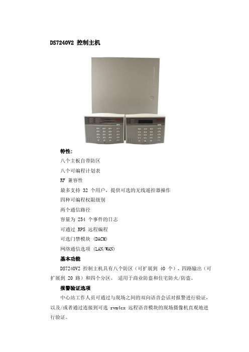
DS7240V2 控制主机特性:八个主板自带防区八个可编程计划表RF 兼容性最多支持 32 个用户,提供可选的无线遥控器操作四种可编程权限级别两个通信路径容量为 254 个事件的日志可通过 RPS 远程编程可选门禁模块 (DACM)网络通信选项 (LAN/WAN)基本功能DS7240V2 控制主机具有八个防区(可扩展到 40 个)、四路输出(可扩展到 20 路)和四个分区。
适用于商业防盗和住宅防火/防盗。
报警验证选项中心站工作人员可通过与现场之间的双向语音会话对报警进行验证,以及/或者通过连接到可选 rvm4cx 远程语音模块的现场摄像机直观地进行验证。
八个主板自带防区DS7240V2 控制主机有八个自带防区。
可以是有线连接扩展防区和无线防区。
可对任何防区进行编程,有 15 个防区功能备选。
DS7240V2 控制主机还允许使用两个电阻对每个传感器回路进行配置。
控制主机将监控每个传感器回路的两个防区,从而提供 16 个主板自带防区。
有线连接扩展防区也具有双防区功能。
对防区的进入和离开延迟时间进行编程时,对于离键盘距离较远的防区,延时可设得稍长一些。
权限级别和 PIN系统支持 32 种个人识别号 (PIN)。
PIN 默认为四位数,但可以选择其它位数:三到七位。
可指定无限数量的主 PIN。
可使用主 PIN 对现有PIN 进行重新编程。
最多可将 PIN 编为四个不同的权限级别,从而限制PIN 对系统进行旁路、测试和撤防。
可本地或远程编程可以通过键盘对系统进行完全编程(需要 DS7447E 或DS7447V2 键盘)。
键盘还有安装程序功能,可快速进入编程菜单。
远程编程软件 (RPS) 是一种基于Windows® 的帐户管理和主机编程及诊断实用程序。
它专门用于在远程(或在本地使用DX4010i Aux Data 针)对 DS7240V2 控制主机进行设置和编程。
LED 和 LCD 键盘支持键盘DS7445i LED 键盘DS7445V2 LED 键盘DS7446KP LCD 键盘DS7447E LCD 键盘DS7447V2 LCD 键盘可在同一 DS7240V2 控制主机系统上混用 LED 和 LCD 键盘。
浔星金牛 Cheetah 73LP 安装指南说明书

Cheetah 73LP Installation GuideModel ST373405LW/LC/LWV/LCV, ST336605LC/LCVSCSI interface disc drivePublication Number: 100109946, Rev. A, April 2001Handling precautions/Electrostatic discharge protection •Disc drives are fragile. Do not drop or jar the drive and handle the drive only by the edges or frame.•Drive electronics are extremely sensitive to static electricity. Keep the drive in its antistatic container until you are ready to install it. Wear a wrist strap and cable connected to ground. Discharge static from all items near or that will contact the drive. Never use an ohmmeter on any circuit boards.•T urn off the power to the host system during installation.•Always use forced-air ventilation when operating the drive.•Use caution when troubleshooting a unit that has voltages present.•Do not disassemble the drive; doing so voids the warranty.•Return the entire drive for depot service if any part is defective.•Do not apply pressure or attach labels to circuit board or drive top.Electromagnetic complianceSee Safety and Regulatory Agency Specifications, p/n 75789512.Drive characteristicsST373405ST336605 Formatted capacity (Gbytes)73.4 36.7Max. data blocks 143,374,74171,687,371(088BB995h)(0445DCCBh) Cylinders (user accessible)29,54929,549Heads (user accessible)84Disc rotation (rpm)10,04110,041 Operating voltages+5V+12V+5V+12VTypical operating current (Amps)0.820.910.820.82What you need•Phillips screwdriver and four 6-32 UNC drive mounting screws•Forced-air ventilation to provide adequate drive cooling•An unused drive power connector from your system’s power supply (not applicable to LC/LCV models because power is supplied through the interface connector on these units)T o operate at LVD transfer rates, you may also need an LVD-capable SCSI host adapter, LVD I/O cable and active negation external terminator. Multimode interfaceThis drive can operate in single-ended (SE) or low voltage differential (LVD) mode. This multimode capability provides backwards compatibility so you can use it with or without an LVD-capable host adapter. The primary bene-fits of LVD technology include faster transfer rates, reduced power con-sumption, increased allowable cable lengths, and improved device connectivity.Y ou can configure the drive to switch between SE and LVD modes automat-ically or force it to operate in SE mode only. To configure this option, see Figure 2.Note.T o operate at the Ultra2 rates in LVD mode, all devices on the same bus (cable) must be running in LVD mode. If you add any SE device to the bus, all devices on that bus operate in SE mode.Note.Some LVD host adapters provide an LVD connector and an SE con-nector on the same host adapter to allow you to run SE and LVD drives concurrently at their maximum capabilities. Check your SCSI host adapter documentation. See Figure 3.Caution.Do not mix LVD drives on the same bus with high voltage differen-tial (HVD) devices–drive damage may occur.Installation instructions1.Set the SCSI IDDetermine which SCSI IDs are already being used in the system and then assign this disc drive a SCSI ID that isn’t already being used. Use the J6 connector located on the front of the drive to set the SCSI ID (see Figure 1). •Most ST373405 drives are factory set with the SCSI ID set at 0. If this is the only SCSI drive in your system and there are no other SCSI deviceson the daisychain, you can leave this drive’s SCSI ID set to 0 and pro-ceed to the next step.•The host system’s SCSI controller usually uses SCSI ID 7.•If you have an LC or LCV model drive, the host normally sets the ID over the I/O interface, so you don’t need to worry about this step.•Some systems provide a cable designed to connect to the J5 jumper block on the drive to remotely set the ID. Y ou can connect this cable to J5Figure 1.Setting the SCSI ID (the J5 block is on LW/LWV models only)2.Configure terminationIf you are installing the drive in a system that has other SCSI devices installed, terminate only the end devices on the SCSI bus (cable). This drive does not have internal terminators or any other way of adding internal termi-nation on the drive. Y ou must provide external termination when termination is required. This is normally done by adding an inline terminator on the end of the cable. See Figure 3 for an illustration showing a system configuration that uses an external terminator.•Use active (ANSI SCSI-2 Alternative 2) single-ended terminators when terminating a bus operating in single-ended mode.•Use SPI-2-compliant active low voltage differential terminators when ter-minating a SCSI Ultra2 bus operating in LVD mode.•The host adapter is normally on the end of the bus and internally termi-nated. Y ou can configure your bus with another device on the end if you remove termination from the host adapter.3.Configure terminator powerTerminators have to get power from some source. The default configuration results in the drive not supplying termination power to the bus. Y ou should normally leave this drive set at this default unless your host system requires the drive to supply termination power to the bus. To configure this drive to supply termination power to the bus, place a jumper on J2 pins 1 and 2 as shown in Figure 2.•Host systems designed to use LC and LCV drives normally provide termi-nation power from the host adapter or other source. For this reason, LC and LCV model drives cannot be configured to provide termination power to the bus.Figure 2.Option select jumpers4.Connect the drive activity LED (optional)Connect the Drive Activity LED cable to J6 pins 11 and 12 (see Figure 2), or connect a drive ID and Drive Activity LED cable to J5, depending on host system requirements.5.Check the other available jumper settingsSelect other options on J2 as illustrated in Figure 2. Do not change these unless instructed to do so by the host system documentation.6.Mount the drive in the host system and connect cablesNote.LC and LCV drives are designed to be attached to a carrier or tray and inserted into the host system without I/O or power cables.a.Mount LW and LWV model drives to the host system’s chassis usingfour 6-32 UNC screws. Two mounting holes are in each side of the drive and there are four mounting holes in the bottom of the drive. Do not over-tighten or force the screws. Y ou can mount the drive in any orienta-tion.b.Connect the SCSI I/O cable into the drive’s SCSI connector. Take carenot to stretch or crimp this cable, and do not block the system’s cooling air flow with the cable.Note.For Ultra2 and faster operation, special twisted pair LVD cables are required.c.Connect the DC power cable to the drive. See Figure 3.Figure 3.Cable connections and external termination7.Format the driveThe drive has been low level formatted at the factory. Y ou do not need to perform another low level format on this drive unless you decide to perform certain diagnostics through the host adapter. If you do decide to perform a low level format, do not abort the format as this is likely to make the drive inoperable. A low level format, with verify turned on, will typically take two hours for ST373405 models and 90 minutes for ST336605 models.Protect against power failure or other power interruptions during the format.a.Turn on DC power to the host system.b.Boot the system from a system floppy, CD, or from a previously installedhard disc drive if there is one.c.Format the drive.Caution.Formatting a drive erases all user data. Be sure that you under-stand this principle before formatting any hard disc drive. It is notnecessary to format a drive that previously has been used tostore data, unless your intention is to erase all user data. Seagateis not responsible for lost user data.Cheetah disc drives are designed to operate with a variety of operating sys-tems. Please refer to your system or SCSI controller manual for information about formatting and setting up the drive. Some quick desktop system notes are provided below.•Microsoft TM. Set the drive type in CMOS to “Zero,” “None,” or “No hard drive installed.” Use FDISK.EXE and FORMA T.EXE. Systems using Win-dows 98 or later can create one single partition (drive letter) on the drive.•Macintosh TM. Use a third-party drive utility (most revisions of Apple’s HD Setup utility only work with drives having special Apple firmware). Troubleshooting•Drive does not spin up. Check cables and all jumper settings. Make sure cable pin 1 (edge stripe) matches PCB pin 1.•Drive spins, but no LED on/off activity. Check SCSI ID setting. Set the ID so that each device on the SCSI chain has its own unique ID. See also the next item below. Host I/O controller is usually ID7.•Computer does not seem to recognize the drive. Verify that the drive is enabled by the SCSI host adapter setup utility.•FDISK does not detect the drive. Run the FDISK program located on your Windows startup diskette. Type fdisk/status to verify that your hard drive is present.Seagate support servicesFor online information about Seagate products, visit or ***********************************************If you need help installing your drive, consult your dealer first. If you need additional help, call a Seagate technical support specialist. Before calling, note your system configuration and drive model number (ST373405LW/ LWV or ST373405LC/LCV).Africa+31-20-316-7222Norway800-113 91 Australia1800-14-7201Poland00 800-311 12 38 Austria0 800-20 12 90Spain900-98 31 24 Belgium0 800-74 876Sweden0 207 90 073 Denmark80 88 12 66Switzerland0 800-83 84 11 France0 800-90 90 52Singapore800-1101-150 Germany************Taiwan+886-2-2514-2237 Hong Kong800-90-0474Thailand001-800-11-0032165 Indonesia001-803-1-003-2165Turkey00 800-31 92 91 40 Ireland 1 800-55 21 22United Kingdom************Italy800-790695USA/Canada/1-800 SEAGA TE or Malaysia1-800-80-2335Latin America+1-405-936-1234 Middle East+31-20-316-7222Other EuropeanNetherlands0 800-732-4283countries+31-20-316-7222 New Zealand0800-443988Warranty. Contact your place of purchase or our web site (above).Return Merchandise Authorization (RMA). Before returning the drive, verify that it is defective. Seagate Worldwide customer service centers are the only facilities autho-rized to service Seagate drives. Contact nearest center for return procedures and trade regulations.Shipping the driveCaution. Back up the data before shipping. Seagate assumes no responsibility for data lost during shipping or service. Shipping drive in an unapproved container voids the warranty. Pack the drive with original box and packing materials. Use no other materials. This prevents electrical and physical damage in transit.© 2001 Seagate T echnology LLC All rights reservedPublication number: 100109946, Rev. A, April 2001, Printed in U.S.A.Seagate, Seagate Technology, and the Seagate logo are registered trademarks of Seagate T echnology LLC. Cheetah is a registered trademark of Seagate T echnology LLC. Other product names are registered trademarks or trademarks of their owners. Seagate reserves the right to change, without notice, product offerings or specifica-tions.。
Fire Alarm Pull Station说明书

OperationThe single-action pull-station isactivated by a single pull-down of the alarm handle. The dual-action versions require pushing in the handle, then pulling the handle down for activation. The PS-DA/PS-SA manual pull stations are UL listed and meet the ADArequirement of a 5-lbs. maximum pull force to activate. Operating instructions are molded into the handle along with Braille text.Molded terminal numbers can be found adjacent to the wiring termi-nals.Models:PS-SA –Single action with ‘pigtail’connections and a key lock reset.Pigtail wires are provided for con-nection to the Fire Alarm Control Panel’s (FACP) initiation circuit.PS-DA –Dual action model with screw terminal connections and a key lock reset.PS-DAH –Same as PS-DA except with hex lock reset.PS-DALOB –Same as PS-DA with “outdoor use” listing. Includes SB-I/O backbox and sealing gasket.PS-DASP –Same as PS-DA except with both English and Spanish operating instructions.Features:•UL Listed •CSFM Listed•Meets ADA requirements•Operating instructions are mold-ed into the handle along with Braille text.•Made of durable Lexan •Available in Spanish •Key resettable•Easy to Install and operate •Single or dual action•Surface mount box availableSpecification:Dimensions:Height:5-1/2” (13.97 cm)Width:4” (10.16 cm)Depth:1-7/16” (3.65 cm)Operating temperature:32°F to 120°F (0°C to 49°C)Electrical:Switch Contact Rating:0.25 A @ 30 VAC or VDCAccessories:SB-I/O Surface Mount Back-box BG-TRTrim RingPS-DA and PS-SAConventional Pull-stationsThe PS-DA/PS-SA Pull Stations are non-coded manual pull stations which provide a Fire Alarm Control Panel (FACP) with a single alarm initiatinginput signal. The PS-DA/PS-SA pull stations includes both single-action and dual-action models equipped with key lock / reset. It was designed to meetmultiple applications with the installer and end-user in mind. Its innovative design, durable construction, and mul-tiple mounting options make the PS-DA and PS-SA simple to install, maintain, and operate.Easy to Install and OperatePS-DAPS-DASPCONVENTIONAL FIRE CONTROL PANEL ACCESSORYCONVENTIONAL FIRE CONTROL PANEL ACCESSORYPS-DA and PS-SAConventional Pull-StationsEngineering SpecificationManual Fire Alarm Stations shall be non-code, with a key-operated reset lock in order that they may be tested,and so designed that after actual Emergency Operation, they cannot be restored to normal except by use of a key. An operated station shall automatically condition itself so as to be visually detected as activated. Manual stations shall be constructed of red colored LEXAN® (or polycarbonate equivalent) with clearly visible operating instructions provided on the cover. The word FIRE shall appear on the front of the stations in white letters, 1.00inches (25.4 mm) or larger.* Stations shall be suitable for surface mounting on matching back-box SB-10; or semi-flush mounting on a standard single-gang, double-gang, or 4" (10.16 cm) square electrical box, and shall be installed within the limits defined by the Americans with Disabilities Act (ADA) or per national/local require-ments. Manual Stations shall be Underwriters Laboratories listed.*NOTE:The words “FIRE/FUEGO” on the PS-DASP shall appear on the front of the station in white letters,approximately 3/4" high.PS-SA Front View PS-DA Front View PS-SA Rear View PS-DA Rear ViewMADE IN AMERICAP/N 350241 Rev.C©2009 Honeywell International Inc.This document is not intended to be used for installation purposes. We try to keep our product information up-to-date and accurate. We cannot cover all specific applications or anticipate all requirements. All specifications are sub-ject to change without notice. For more information, contact Silent Knight 12Clintonville Road Northford, CT 06472-1610 Phone: (800) 328-0103, Fax: (203) 484-7118. 。
Firetrol Mark IIXG型电动消防泵控制器使用手册说明书
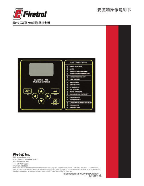
安装和操作说明书Fire Pump Controllers General InformationCalifornia Proposition 65WarningWARNING : This product can expose you to chemicals including DINP, which is known to the State of California to cause cancer, and DIDP which is known to the State of California to cause birth defects or other reproductive harm.WARNING : This product can expose you to chemicals including lead and lead compounds, which are know to the State of California to cause cancer and birth defects or other reproductive harm.For more information go to: 3412 Apex Peakway Apex, North Carolina 27502P +1 919 460 5200F +1 919 460 目 录介绍 (1)安装控制器 (2)墙式安装 (2)地板/基座式安装 ....................................................................................................................2-3电气连接 ................................................................................................................................3-4系统压力连接管 . (4)一般预启动操作 (4)一般启动操作 (4)相位旋转 (5)电机旋转方向FTA750、1000、1500、1800、2000、2400控制器 (5)FTA1250 控制器 (5)FTA1300、1350 控制器..............................................................................................5-6 FTA1930 控制器 . (6)FTA900、975电源转换开关 (6)FTA950、976电源转换开关 (6)初始启动操作 (7)手动启动 (7)应急运行启动 (7)简单启动顺序FTA750, 1000, 2000, 2400 (7)FTA1250 .....................................................................................................................7-8 FTA1300, 1350 (8)FTA1500 (8)FTA1800 (8)FTA1930 (8)型IIXG程序设置用户界面和显示器 (9)用户菜单结构 (10)程序设置说明 (11)菜单设置系统设置显示亮度 (12)对比度 (12)反向 (12)键盘 (12)语言和单元语言 (12)压力单位 (12)密码1级 (12)2级 (12)日期和时间时间 (12)日期 (12)日期格式 (12)日光节约 (13)定时器延时开机 (13)最短运行/关机延迟 (13)加速 (13)子系统旁路 (13)压力压力单位 (14)启动 (14)停止 (14)禁用自动停机 (14)过压报警 (14)记录 -德耳塔 (14)传感器 (14)校正 (14)恢复默认设置 (14)电机和电源电压 (14)相序 (15)频率 (15)全负荷安培数 (15)CT 比值 (15)过负荷 (15)数字软启动电机 FLA (15)初始化电流 (15)最大电流 (15)斜坡加速时间 (15)UTS定时器 (15)减速开始水平 (15)减速中止水平 (15)减速中止时间 (15)减速结束水平 (15)斜坡减速时间 (15)相位旋转 (15)启用超时 (15)超时 (15)全负荷电流 (16)CT比值 (16)TX (16)RX (16)误差 (16)微调电压 (16)报警极限过压报警 (16)最小电压 (16)最大电压 (16)最小频率 (16)最大频率 (16)不平衡 (16)过负荷 (16)功能设置互锁报警 (17)低压力声音报警 (17)低吸入压力 (17)泵运行报警 (17)用户输入 (17)每周测试 ..........................................................................................................17-18选项设置 .. (18)主菜单- 事件日志 (18)主菜单-数据历史 (18)主菜单 USB储存到 USB (18)移出驱动器 (19)工厂配置序列号 (19)型号 (19)马力 (19)电压 (19)全负荷电流 (19)CT 比值 (19)频率 (19)相序 (19)压力传感器 (19)自动启动 NC (19)用户输入数字 (19)低吸入压力 (19)配置 - 选项 (20)配置 – 模数转换器 校正 (20)诊断原始输入:模拟 (20)原始输入:独立部件 (20)原始输入:键 (20)原始输出:独立部件 (20)IIXG型启动 (20)指示灯测试 (20)声音报警测试 (20)USB 测试 (20)相位失锁 (20)相序逆转 (20)并联跳闸装置1 (21)并联跳闸装置2 (21)标志 (21)工具清除数据历史 (21)清除事件日志 (21)恢复出厂设置 (21)固件更新 (21)关于......................................... (21)警告在设备通电期间,禁止安装或维护设备!接触通电设备可能造成死亡、人身伤害或大量财产损失。
泰和安报价表Ver.201407(7月印制)

目录
一、火灾探测器及接口部件 1 ································································································· 二、现场模块及指示部件 1 ······································································································ 三、各类火灾报警、联动控制器 3 ······················································································ 四、气体灭火控制设备 13 ·········································································································· 五、扩展操作盘 13 ························································································································· 六、机柜、机箱 14 ························································································································· 七、火灾显示盘 14 ························································································································· 八、直流不间断电源 14 ·············································································································· 九、中央管理软件及接口设备 15 ························································································· 十、网络接口设备 15 ··················································································································· 十一、消防广播系统 15 ·············································································································· 十二、消防电话系统 16 ·············································································································· 十三、防爆产品系列 16 ·············································································································· 十四、蓄电池及备品备件 18 ···································································································· 十五、消防应急照明与疏散指示系统 19 ·········································································· 十六、电气火灾监控设备 21 ···································································································· 十七、电气火灾探测器 22 ········································································································· 十八、互感器 23 ······························································································································ 十九、测温式探测器 23 ··············································································································
海康威视总线制报警主机操作手册

警告 事项提醒用户防范潜在的 注意 事项提醒用户防范潜在的 说明 事项提醒用户附加或强调
死亡或严重伤害危险。
伤害或财产损失危险。
的信息。
警告 在本产品安装使用中,必须严格遵守国家和使用地区的各项电气安全规程。 在接线、拆装等操作时请一定要将电源断开,切勿带电操作。 如果设备工作不正常,请联系购买设备的商店或最近的服务中心,不要以任何方式拆卸或修改设备。
1.1 功能简介 .................................................................................................................................... 9 1.2 功能特性 .................................................................................................................................... 9 1.3 防区类型说明 .......................................................................................................................... 10 1.4 布防类型说明 .......................................................................................................................... 11
2.2.1 探测器接线 ....................................................................................................................... 13 2.2.2 触发器输出接线 ............................................................................................................... 14 2.2.3 电源接线 ........................................................................................................................... 15 2.2.4 防拆开关接线 ................................................................................................................... 15 2.2.5 键盘接线 ........................................................................................................................... 16 2.2.6 警号接线 ........................................................................................................................... 16 2.2.7 电话接线 ........................................................................................................................... 17 2.2.8 GPRS 接线 ......................................................................................................................... 17 2.2.9 辅电接线 ........................................................................................................................... 18 2.2.10 总线扩展接线 ................................................................................................................... 18
安舍火灾报警计算机控制系统安装指南789982
安舍火灾报警计算机控制系统安装指南789982
安舍108火灾报警系统主要由七个部分构成:
(1)安舍1Q8系列火灾报警控制器安舍1Q8 Con r o l M型火灾报警控制器、安舍108 Control C型火报警控制兴、安会108型火灾报警控制器联动型y。
(2)安全多样化、多种类单体及多重复合探测票。
(3)安合手动报警按销。
(4)安舍多功能智能输入输出模块。
(5)安舍108Wreless无线探测器及网关。
(6)安合RS232中文图形监控系统。
(7)安会RS232与BA系统通讯接口。
计算机化、模块化和通用化扩展插槽式结构使该系统的控制器在系统构成上,变得更灵活、更具适应性、应用也更广泛。
用户和设计人员可根据各自的要求,任意选择组合,任意扩展功能。
网络技术的应用使得火灾报警可跨区域管理,各控制器之间的互联互控,探测回路上环路与支路的并举,探测器及控制单元的线路自动编码及自动寻址,以及整个系统的远程监视维护都成了现实。
同时,使探测器的报警及联动更准确、更可靠,系统的抗干扰性大大提高,故障率及误报率大大降低。
对探测器而言,采样分析、火警判断、数据储存、各种参数的自动补尝等工作都可独立完成,从而将整个系统的性能指标提高到了一个新的水平。
7420主机设置程序无线
报警主机设置方法:(7240无线)一、设置主机的基本程序:9876#418;进入编程状态7240#1※;打开超级管理员权限2944#1※;恢复出厂设置1026#2※;EOL电阻值为2.2K1249#1※;无线接收机的选择(单接收机1、双接收机3)1250#0※1032#0※1033#0※注:程序中有下划线的为不确定值,根据实际情况选择,主机出厂默认用户密码为1234,安装密码为9876。
如有双键盘设置应该再添加以下设置:(副控键盘的地址跳线2应短接)0680 # 7 *0681 # 1 *二、设置9~33防区的防区类型为瞬时防区747#15※;设置第09防区为瞬时防区752#15※;设置第10防区为瞬时防区757#15※;设置第11防区为瞬时防区762#15※;设置第12防区为瞬时防区767#15※;设置第13防区为瞬时防区772#15※;设置第14防区为瞬时防区777#15※;设置第15防区为瞬时防区782#15※;设置第16防区为瞬时防区787#15※;设置第17防区为瞬时防区792#15※;设置第18防区为瞬时防区797#15※;设置第19防区为瞬时防区802#15※;设置第20防区为瞬时防区807#15※;设置第21防区为瞬时防区812#15※;设置第22防区为瞬时防区817#15※;设置第23防区为瞬时防区822#15※;设置第24防区为瞬时防区827#15※;设置第25防区为瞬时防区832#15※;设置第26防区为瞬时防区837#15※;设置第27防区为瞬时防区842#15※;设置第28防区为瞬时防区847#15※;设置第29防区为瞬时防区852#15※;设置第30防区为瞬时防区857#15※;设置第31防区为瞬时防区862#15※;设置第32防区为瞬时防区867#15※;设置第33防区为瞬时防区872#15※;设置第34防区为瞬时防区877#15※;设置第35防区为瞬时防区882#15※;设置第36防区为瞬时防区887#15※;设置第37防区为瞬时防区892#15※;设置第38防区为瞬时防区897#15※;设置第39防区为瞬时防区902#15※;设置第40防区为瞬时防区三、设置9~33防区的设备类型746#4※;设置第09防区使用1号接收机751#4※;设置第10防区使用1号接收机756#4※;设置第11防区使用1号接收机761#4※;设置第12防区使用1号接收机766#4※;设置第13防区使用1号接收机771#4※;设置第14防区使用1号接收机776#4※;设置第15防区使用1号接收机781#4※;设置第16防区使用1号接收机786#4※;设置第17防区使用1号接收机791#4※;设置第18防区使用1号接收机796#4※;设置第19防区使用1号接收机801#4※;设置第20防区使用1号接收机806#4※;设置第21防区使用1号接收机811#4※;设置第22防区使用1号接收机816#4※;设置第23防区使用1号接收机821#4※;设置第24防区使用1号接收机826#4※;设置第25防区使用1号接收机831#4※;设置第26防区使用1号接收机836#4※;设置第27防区使用1号接收机841#4※;设置第28防区使用1号接收机846#4※;设置第29防区使用1号接收机851#4※;设置第30防区使用1号接收机856#4※;设置第31防区使用1号接收机861#4※;设置第32防区使用1号接收机866#4※;设置第33防区使用1号接收机871#4※;设置第34防区使用1号接收机876#4※;设置第35防区使用1号接收机881#4※;设置第36防区使用1号接收机886#4※;设置第37防区使用1号接收机891#4※;设置第38防区使用1号接收机896#4※;设置第39防区使用1号接收机901#4※;设置第40防区使用1号接收机※(按住3秒钟);退出编程状态注:(7240防盗主机共支持40个防区,1~8防区为有线防区,9~40为扩展防区,在扩展防区不超过32个时,一般不占用1~8防区,1~8防区可以作为主机开盖报警等功能使用;以下程序设置中打开了9~40个防区,可根据需要设置,如果不需要32个防区,程序中不能打开,可根据实际情况删除对应防区的设置;在设备类型选择程序中,数字4代表1号接收机,数字5代表2号接收机,选择时以报警发射模块与接收天线距离近为第一原则)。
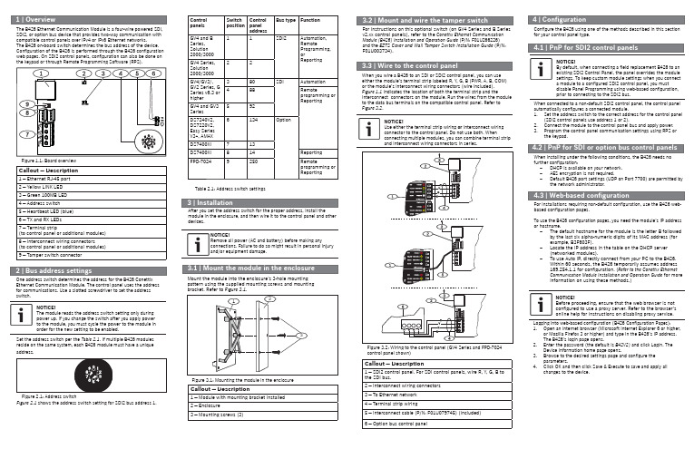
Brainlink B426智能电源模块用户指南说明书
module in the enclosure, and then wire it to the control panel and otherdevices.NOTICE!Remove all power (AC and battery) before making anyconnections. Failure to do so might result in personal injuryand/or equipment damage.Mount the module into the enclosure’s 3-hole mountingpattern using the supplied mounting screws and mountingbracket. Refer to Figure 3.1.Figure 3.1: Mounting the module in the enclosureCallout ― Description1 ― Module with mounting bracket installed2 ― Enclosure3 ― Mounting screws (3)When you wire a B426 to an SDI or SDI2 control panel, you can useeither the module’s terminal strip labeled R, Y, G, B (PWR, A, B, COM)or the module’s interconnect wiring connectors (wire included).Figure 1.1 indicates the location of both the terminal strip and theinterconnect connectors on the module. Run the wires from the moduleto the data bus terminals on the compatible control panel. Refer toFigure 3.2.NOTICE!Use either the terminal strip wiring or interconnect wiringconnector to the control panel. Do not use both. Whenconnecting multiple modules, you can combine terminal stripand interconnect wiring connectors in series.For instructions on this optional switch (on GV4 Series and B Seriesv2.xx control panels), refer to the Conettix Ethernet CommunicationModule (B426) Installation and Operation Guide (P/N: F01U266226)and the EZTS Cover and Wall Tamper Switch Installation Guide (P/N:F01U003734).Set the address switch per the Table 2.1. If multiple B426 modulesreside on the same system, each B426 module must have a uniqueaddress.Callout ― Description1 ― SDI2 control panel. For SDI control panels, wire R, Y, G, B tothe SDI bus.2 ― Interconnect wiring connectors3 ― To Ethernet network4 ― Terminal strip wiring5 ― Interconnect cable (P/N: F01U079745) (included)6 ―Option bus control panelFigure 3.2: Wiring to the control panel (GV4 Series and FPD-7024Confi gure the B426 using one of the methods described in this sectionfor your control panel type.NOTICE!By default, when connecting a fi eld replacement B426 to anexisting SDI2 Control Panel, the panel overrides the modulesettings. To keep custom module settings when you connecta module to a confi gured SDI2 control panel, you mustdisable Panel Programming using web-based confi guration,prior to connecting to the SDI2 bus.When connected to a non-default SDI2 control panel, the control panelautomatically confi gures a connected module.1. Set the address switch to the correct address for the control panel(SDI2 control panels use address 1 or 2).2. Connect the module to the control panel bus and apply power.3. Program the control panel communication settings using RPS orthe keypad.NOTICE!Before proceeding, ensure that the web browser is notconfi gured to use a proxy server. Refer to the browser’sonline help for instructions on disabling proxy service.When installing under the following conditions, the B426 needs nofurther confi guration:–DHCP is available on your network.–AES encryption is not required.–Default B426 port settings (UDP on Port 7700) are permitted bythe network administrator.For installations requiring non-default confi guration, use the B426 web-based confi guration pages.To use the B426 confi guration pages, you need the module’s IP addressor hostname.–The default hostname for the module is the letter B followedby the last six alpha-numeric digits of its MAC address (forexample, B3F603F).–Locate the IP address in the table on the DHCP server(networked modules).–To use Auto IP, directly connect from your PC to the B426.Within 60 seconds, the B426 temporarily assumes address169.254.1.1 for confi guration. (Refer to the Conettix EthernetCommunication Module Installation and Operation Guide for moreinformation on using these methods.)Logging into web-based confi guration (B426 Confi guration Pages):1. Open an internet browser (Microsoft Internet Explorer 6 or higher,or Mozilla Firefox 3 or higher) and type in the B426’s IP address.The B426’s login page opens.2. Enter the password (the default is B42V2) and click Login. TheDevice Information home page opens.3. Browse to the desired settings page and confi gure theparameters.4. Click OK and then click Save & Execute to save and apply allchanges to the device.control panel shown)NOTICE!The module reads the address switch setting only duringpower up. If you change the switch after you apply powerto the module, you must cycle the power to the module inorder for the new setting to be enabled.One address switch determines the address for the B426 ConettixEthernet Communication Module. The control panel uses the addressfor communications. Use a slotted screwdriver to set the addressswitch.Figure 2.1 shows the address switch setting for SDI2 bus address 1.Figure 2.1: Address switchTable 2.1: Address switch settingsControlpanelsSwitchpositionControlpaneladdressBus type FunctionGV4 and BSeries,Solution2000/300011SDI2Automation,RemoteProgramming,orReportingGV4 Series,Solution2000/300022GV4/GV3/,GV2 Series, GSeries v6.3 orhigher380SDI Automation488Remoteprogramming orReportingGV4 and GV3Series592DS7240V2,DS7220V2,Easy SeriesV3+, AMAX6134OptionDS7400Xi713DS7400Xi814ReportingFPD-70249250Remoteprogramming orReportingThe B426 Ethernet Communication Module is a four-wire powered SDI,SDI2, or option bus device that provides two-way communication withcompatible control panels over IPv4 or IPv6 Ethernet networks.The B426 on-board switch determines the bus address of the device.Confi guration of the B426 is performed through the B426 confi gurationweb pages. On SDI2 control panels, confi guration can also be done onthe keypad or through Remote Programming Software (RPS).Figure 1.1: Board overviewCallout ― Description1 ― Ethernet RJ-45 port2 ― Yellow LINK LED3 ― Green 100MB LED4 ― Address switch5 ― Heartbeat LED (blue)6 ― TX and RX LEDs7 ― Terminal strip(to control panel or additional modules)8 ― Interconnect wiring connectors(to control panel or additional modules)9 ― Tamper switch connectorCopyrightThis document is the intellectual property of Bosch Security Systems, Inc. and is protected by copyright. All rights reserved.TrademarksAll hardware and software product names used in this document are likely to be registered trademarks and must be treated accordingly.Bosch Security Systems, Inc. product manufacturing datesUse the serial number located on the product label and refer to the Bosch Security Systems, Inc. website at /datecodes/.Dimensions 59.5 mm x 108 mm x 16 mm (2.19 in x 4.25 in x 0.629 in)Voltage (operating)12 VDC nominal Current (maximum)100 mA maxConnectors LAN/WAN: RJ-45 modular port (Ethernet)Ethernet cable Category 5 or better unshielded twisted pair, 100 m (328 ft) max length InterfaceIEEE 802.3Data bus wire size 1.02 mm to 0.65 mm (18 AWG to 22 AWG)Data bus wire lengthMaximum distance - Wire size:150 m (500 ft) - 0.65 mm (22 AWG)300 m (1000 ft) - 1.02 mm (18 AWG)Web browser Microsoft Internet Explorer 6 or higher; Mozilla Firefox 3 or higher CompatibilityD9412, D7412, D7212, D9112G Series Version 6.3 or higher GV2 Series GV3 Series GV4 Series B SeriesDS7240 Version 2.10 or higher DS7220 Version 2.10 or higher Easy series V3+DS7400Xi Version 4.10 or higher FPD-7024 Version 1.02 or higher AMAX 2000/2100/3000/4000Solution 2000/3000The B426 module includes the following on-board LEDs to assist with troubleshooting issues:– Heartbeat (system status). – RX (receve). – TX (transmit).Flash patternFunctionFlashes once every 1 sec Normal state: Indicates normal operation state.3 quick fl ashes every 1 secCommunication error state: Indicates a bus communication error. The module is not receiving commands from the control panel.On Steady Trouble state. Indicates a trouble condition exists.OffLED trouble state. Module is not powered, or some other trouble condition prohibits the module from controlling the heartbeat LED.Table 4.1: Heartbeat LED descriptionsFlash patternFunctionRX (Receive) fl ashes Occurs when the module receives a messageover the network connection – UPD, TCP, or DNS.TX (Transmit) fl ashesOccurs when the module sends a message over the network connection – UPD, TCP, or DNS.Table 4.2: RX and TX LEDs descriptionsLINK (yellow)fl ash pattern100mb (green)fl ash patternFunctionOff Off No Ethernet link On Steady Off 10 BASE-T link Flash Off 10 BASE-T activity On Steady On Steady 100 BASE-T link FlashOn Steady100 BASE-T activityTable 4.3: Ethernet LINK and 100mb LEDs descriptionsRegion Certi fi cationApplicable control panelsUSUL 365 – Police Station Connected Burglar Alarm Units and Systems B Series, GV4 Series, GV3 Series, GV2 Series UL 609 – Local Burglar Alarm Units and SystemsB Series, GV4 Series, GV3 Series, GV2 Series UL 864 – Control Units and Accessories for Fire Alarm Systems(Including NFPA 72)GV4 Series, GV3 Series, GV2 Series, FPD-7024UL 985 – Household Fire Warning System Units B Series, GV4 Series, GV3 Series, GV2 Series UL 1023 – Household Burglar Alarm System Units B Series, GV4 Series, GV3 Series, GV2 Series UL 1076 – Proprietary Burglar Alarm Units and Systems B Series, GV4 Series, GV3 Series, GV2 Series UL 1610 – Central Station Burglar Alarm Units B Series, GV4 Series, GV3 Series, GV2 SeriesFCC Part 15 Class B, NIST FIPS-197 AES Certi fi cation (IP Communications)B Series, GV4 Series, GV3 Series, GV2 Series, G Series, DS7200, DS7400, Easy Series V3+, AMAX 2000CanadaCAN/ULC S303 - Local Burglar Alarm Units and SystemsB Series, GV4 Series, GV3 Series, GV2 Series CAN/ULC S304 - Signal Receiving Centre and Premise Alarm Control UnitsB Series, GV4 Series, GV3 Series, GV2 Series ULC-ORD C1023 - Household Burglar Alarm System Units B Series, GV4 Series, GV3 Series, GV2 Series ULC-ORD C1076 - Proprietary Burglar Alarm Units and SystemsB Series, GV4 Series, GV3 Series, GV2 Series ICES-003 - Digital ApparatusB Series, GV4 Series, GV3 Series, GV2 Series EU EN 50130-4, EN 61000-6-3, EN 60950DS7200, DS7400, Easy Series V3+, AMAX 2000/2100/3000/4000AustraliaC-TickEasy Series V3+Table 4.4: Trouble conditions indicated through LEDsConditionHeartbeatTransmit (TX)Receive (RX)Network cabledisconnectedOn SteadyOff1 quick fl ash, repeating Obtaining an IP addressOn Steady Off2 quick fl ashes, repeatingLow bus voltageOn Steady Off3 quick fl ashes, repeatingInternal failure On Steady On Steady On Steady。
BOSCH-DS7240简易说明书

DS7240简易说明书一、键盘编程进入、退出、恢复出厂设置(1)进入安装编程模式:系统在撤防状态(所有分区)输入安装员密码(出厂值为9876)按#41,键盘显示功能菜单按8,进入键盘编程模式,键盘显示软件版本DS7420 Revision V2.1,并自动跳到地址0000的位置,显示Adr.0000 D=0按7240# 1*进入高级编程状态(2)退出编程模式按#持续3秒,退出编程,数据不保存按*持续3秒,退出编程,数据保存(3)恢复出厂设置在高级编程状态下,输入2944# 1*二、操作说明出厂用户1的密码为1234日期时间设定:#45,输入时间和日期(DD/MM/YY HH:MM),每次断电后重新上电要重新设定时间全部布防:输入密码+按布防键强制布防:输入密码+按布防键2次撤防/解除报警:输入密码+按撤防键旁路防区:按旁路键,输入防区号(1-40)+*进行旁路,按#退出查看报警记录:#40进入查看,按#退出查看系统故障:#42进入查看,按#退出查看防区故障:#48进入查看,按#退出系统测试:按41进行测试,按#退出重置系统:#47或长按复位键三、键盘编程进入高级编程状态后操作,每一个编程地址由4位数字组成(0-9999),每个编程地址都有一个编程值(0-15)。
(1)设置中心电话号码第一中心:0000-0031,0032-0063(以87504321八位号码为例)第二中心:0066-0097,0098-0129(2)设置接收机报告格式(需与接警中心确认具体报告格式,以下以Contact ID格式为例)设置接收机1报告格式:0064# 2*设置接收机2报告格式:0130# 2*[说明] 格式代码定义:1:保留;2:Contact ID;3:SIA 300;4:Basec Pager;7:个人拨号格式;11:SIA 300(带文本)(3)设定用户编号(需与接警中心确认具体用户编号,以下以1204为例)(4)设定防区功能(以下只列出1-8防区,其他请参与附带安装手册)(5)设定进入退出延时时间(6)设定警号输出时间地址:1040,编程值:0-15分钟。
电器平安性能检测台

电器平安性能检测台组装型操作指导感激您购买和利用咱们的产品,为了保证平安、正确地利用本产品,敬请用户在操作之前详细阅读本产品说明书的全数内容。
本说明书适用以下型号的电器综合测试仪:LH-6: 可测试项目<耐压,接地,泄漏,绝缘,低压启动,功率> LH-4: 可测试项目<耐压,接地,泄漏,绝缘>LH-4A: 可测试项目<耐压,接地,泄漏,功率>本说明书含有开箱检查、平安警告事项、产品的要紧技术指标、产品利用操作方式和常见故障处置等一系列内容。
在编写进程中,咱们已经尽力确保本说明书内容的全面性和准确性。
若是用户在利用进程中有疑问,或发觉有不足和错误的地方,欢迎直接与本公司联系。
用户对说明书若是有不同明白得,以本公司技术部的说明为准。
本说明书的内容或个别地址可能发生改变,恕不另行通知。
请用户妥帖保管本说明书,以保证测试台的正常利用。
2平安警告事项在利用本测试台的进程中必需注意以下平安规定,如不遵守本规定,产品功能可能受损并危及人身平安,与本公司无关。
注意:★勿在侵蚀性环境中利用本产品不要在含有侵蚀性液体或气体的地址利用本产品,不然将对本产品造成损害。
★勿在爆炸性环境下操作不要在放有易燃易爆品的地址利用本产品,不然可能危及平安。
★采纳标准电源插座采纳单相250V/10A三极标准电源插座,其接地极必需与地线相连。
★爱惜地线打开电源前请确保接好本产品的爱惜地线,且应幸免将零线用作爱惜地线。
★供电电源打开电源前确保供电电源电压与额定电压相符。
本产品利用的电源标准为AC220V±10%、50Hz。
★保险丝为幸免火灾,请利用标准保险丝(2A),改换保险丝前,切断电源和负载,勿用不符合要求的保险丝或短接保险丝管座。
★保护事项在确保切断电源及拨下电源插头的情形下,方可进行测试台的日常保护、清洁或改换保险丝等工作。
测试台内部清洁工作及故障修理,必需由专业人员操作。
平常禁止打开机箱,以避免发生触电事故。
台湾无线燃气报警控制器功能区的键盘介绍

台湾无线燃气报警控制器功能区的键盘介绍
台湾无线燃气报警控制器的功能区键盘一般包括以下几个按键:
1. 开关/复位按键:用于打开或关闭燃气报警控制器的电源,或进行系统的复位操作。
2. 报警静音按键:用于静音报警器,通常在确认误报时使用。
3. 解除报警按键:用于解除燃气报警状态,通常在确认无报警情况下使用。
4. 系统设置按键:用于进行系统参数的设置和调整,比如设置报警阈值、报警延时等。
5. 消防应急呼叫按键:用于紧急情况下向消防部门发送求助信号。
值得注意的是,具体的键盘布局和按键功能可能因产品型号和品牌而有所不同,以具体产品说明书或用户手册为准。
同时,在操作过程中,请仔细阅读产品说明,遵循正确的使用方法,确保安全。
