MAP130-4004G中文资料
NUC130中文手册

3
编号信息列表及管脚名称定义 ................................................................................................... 12
3.1 NuMicro™ NUC130产品选型指南 ................................................................................. 12
3.2.1 NuMicro™ NUC130管脚图 ..............................................................................................13
3.3 管脚功能描述 ................................................................................................................ 16
5.5 I2C 串行接口控制器 (Master/Slave) (I2C)...................................................................... 44
5.5.1 概述.................................................................................................................................44 5.5.2 特征.................................................................................................................................45
Flexi

5
1
产品介绍 系统原理图
Flexi Cluster 系统由FMC ,mHub和mAP组成的三级架构系统; FMC 系统中DCS从信源RRU耦合信号,LTE通过FMC设备内部的FWNC(NOKIA小站)设 备提供信号,系统采用数字传输方式,通过光纤传输到mHub ,mHub进行数字信号分配后
通过光纤传输给多个mAP, mAP对信号进行数字处理后放大,通过天线实现覆盖;
mAP可以在对应的mHub任意2小区选一个;
2G+4G(DCS 25MHZ;LTE 40MHz(50MHz内可移, E频段)设备中光模块要求为:FMC与 mHub/mHub与mHub设备之间均使用6Gb/s速率光模块; mHub 与mAP设备之间使用3Gb/s速率光模块; 9
1
产品介绍
小区扩容功能
19
3
勘测事项
Ncs:小区最大接入半径
对基站覆盖区进行测试,获得基站小区输出信号的PCI、ID、EARFCN、基站覆 盖区上传下载吞吐量、单双流开通情况以及基站小区Ncs循环移位设臵情况等
信息;
注:Ncs循环移位(小区最大切换接入半径),假设室内基站Ncs值设为6,对应覆盖距离5.7km; Flexi Cluster 设备内部时延7us,最大光纤拉远距离为(5.7km/0.3km-7us) *0.2km/us=2.4km;超过2.4km拉远距离需要调整循环移位参数,否则影响外部进入该覆盖区
重 量
FMC:约5kg(整机重量) mHub:约3kg(整机重量) mAP:约1.5kg(整机重量)
15
1
产品介绍
设备主要性能指标——环境特性
分类 FMC :-10℃~+45℃ mHub:-10℃~+45℃ Map :-10℃~+45℃ 特性
MSP430中文数据手册

MSP430混合信号微控制器数据手册产品特性●低电压范围:2.5V~5.5V●超低功耗——活动模式:330μA at 1MHz, 3V——待机模式:0.8μA——掉电模式(RAM数据保持):0.1μA●从待机模式唤醒响应时间不超过6μs●16位精简指令系统,指令周期200ns●基本时钟模块配置——多种内部电阻——单个外部电阻——32kHz晶振——高频晶体——谐振器——外部时钟源●带有三个捕获/比较寄存器的16位定时器(Timer_A)●串行在线可编程●采用保险熔丝的程序代码保护措施●该系列产品包括——MSP430C111:2K字节ROM,128字节RAM——MSP430C112:4K字节ROM,256字节RAM——MSP430P112:4K字节OTP,256字节RAM●EPROM原型——PMS430E112:4KB EPROM, 256B RAM●20引脚塑料小外形宽体(SOWB)封装,20引脚陶瓷双列直插式(CDIP)封装(仅EPROM)●如需完整的模块说明,请查阅MSP430x1xx系列用户指南(文献编号:SLAU049产品说明TI公司的MSO43O系列超低功耗微控制器由一些基本功能模块按照不同的应用目标组合而成。
在便携式测量应用中,这种优化的体系结构结合五种低功耗模式可以达到延长电池寿命的目的。
MSP430系列的CPU采用16位精简指令系统,集成有16位寄存器和常数发生器,发挥了最高的代码效率。
它采用数字控制振荡器(DCO),使得从低功耗模式到唤醒模式的转换时间小于6μs.MSP430x11x系列是一种超低功耗的混合信号微控制器,它拥有一个内置的16位计数器和14个I/0引脚。
典型应用:捕获传感器的模拟信号转换为数据,加以处理后输出或者发送到主机。
作为独立RF传感器的前端是其另一个应用领域。
DW封装(顶视图)可用选型功能模块图管脚功能简介:1.CPUMSP430的CPU采用16位RISC架构,具有高度的应用开发透明性。
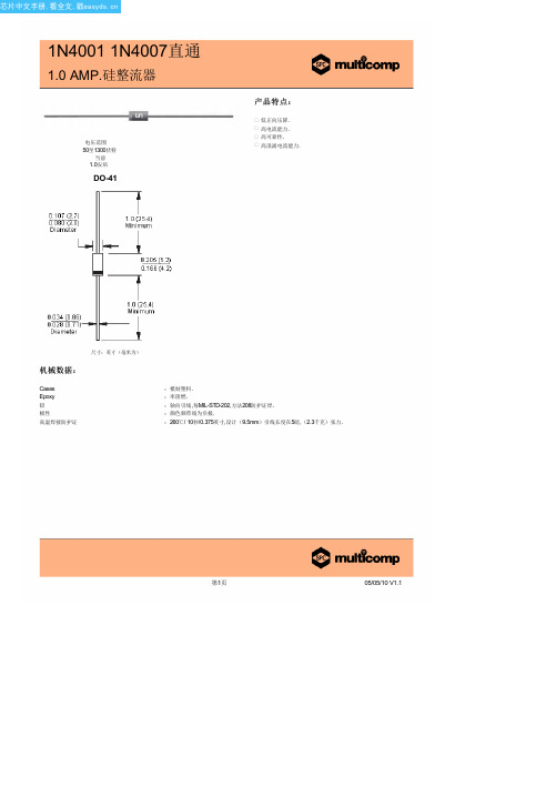
型号1N4004(MULTICOMP)中文数据手册「EasyDatasheet」
pF °C/W
°C
典型正向特性
安培
平均正向整流电流 环境温度(℃)
瞬时正向电流( A) 正向电压( V)
第2页
07/05/10 V1.1
芯片中文手册,看全文,戳
1N4001 1N4007直通
1.0 AMP.硅整流器
额 定 值 和 特 性 曲 线 ( 1N4001)
最大非重复正向浪涌电流
第3页
07/05/10 V1.1
第1页
05/05/10 V1.1
芯片中文手册,看全文,戳
1N4001 1N4007直通
1.0 AMP.硅整流器
最大额定值和电气特性:
评分在25°C环境温度,除非另有规定. 单相,半波,60赫兹,电阻或电感性负载. 对于容性负载,减免电流20%.
型号数量
最大经常峰值反向电压
最大RMS电压
典型结电容
峰值正向浪涌电流( A) 循环次数在 60Hz
典型反向特性
µ
瞬时反向电流( μA)
额定峰值反向电压百分比(%)
结电容( pF) 反向电压( V)
Disclaimer This data sheet and its contents (the "Information") belong to the Premier Farnell Group (the "Group") or are licensed to it. No licence is granted for the use of it other than for information purposes in connection with the products to which it relates. No licence of any intellectual property rights is granted. The Information is subject to change without notice and replaces all data sheets previously supplied. The Information supplied is believed to be accurate but the Group assumes no responsibility for its accuracy or completeness, any error in or omission from it or for any use made of it. Users of this data sheet should check for themselves the Information and the suitability of the products for their purpose and not make any assumptions based on information included or omitted. Liability for loss or damage resulting from any reliance on the Information or use of it (including liability resulting from negligence or where the Group was aware of the possibility of such loss or damage arising) is excluded. This will not operate to limit or restrict the Group's liability for death or personal injury resulting from its negligence. SPC Multicomp is the registered trademark of the Group. © Premier Farnell plc 2010.
CD4013中文资料及应用
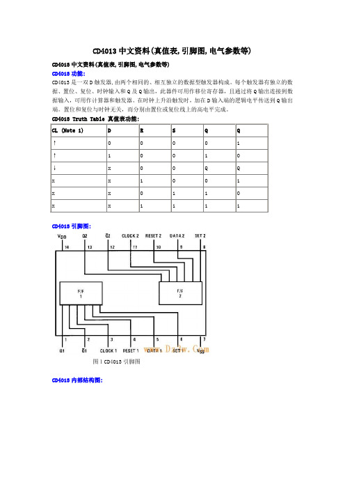
CD4013中文资料(真值表,引脚图,电气参数等)CD4013中文资料(真值表,引脚图,电气参数等)CD4013功能:CD4013是一双D触发器,由两个相同的、相互独立的数据型触发器构成。
每个触发器有独立的数据、置位、复位、时钟输入和Q及Q输出,此器件可用作移位寄存器,且通过将Q输出连接到数据输入,可用作计算器和触发器。
在时钟上升沿触发时,加在D输入端的逻辑电平传送到Q输出端。
置位和复位与时钟无关,而分别由置位或复位线上的高电平完成。
CD4013 Truth Table 真值表功能:CL (Note 1) D R S Q Q↑0 0 0 0 1↑ 1 0 0 1 0↓x 0 0 Q Qx x 1 0 0 1x x 0 1 1 0x x 1 1 1 1CD4013引脚图:图1CD4013引脚图CD4013内部结构图:图2CD4013内部电路图图3 CD4013逻辑图CD4013电气参数:Absolute Maximum Ratings 绝对最大额定值:DC Supply Voltage 直流供电电压 (VDD) -0.5 VDC to +18 VDC Input Voltage输入电压 (VIN) -0.5 VDC to VDD +0.5 VDC Storage Temperature Range储存温度范围 (TS) -65℃ to +150℃Recommended Operating Conditions 建议操作条件:DC Electrical Characteristics 直流电气特性:AC Electrical Characteristics 交流电气特性:图4 切换时间波形CD4013应用电路:图5(左)和图(右)中的CD4013是CMOS双D触发器,这类电路置位和复位信号是高电平有效,由于开关闭合时电容可视为短路而产生高电平,使RD=1,Q=0;若将此信号加到SD,则SD=1,Q=1;置位、复位过后,电容充电而使RD(SD)变为0,电路可进入计数状态。
三相多功能电力监控仪PM130EH

PM130 PLUS QuickstartQuick Start GuidePM130 PLUSSeriesPowermetersBG0441 REV.A7PM130 PLUS Quickstart2Figure 1: Instrument DimensionsPM130 PLUS Quickstart3Figure 2: Mounting the PM130 PLUS (Square or Round cut-out)PM130 PLUS Quickstart4 NOTE:Refer to the Installation and operation manual for the wiring schematics diagramsFigure 3: Common Wiring Mode: 4LL3 or 4L-n3Wiring Configuration Setup Code3-wire 2-element Direct connection using 2 CTs 3dir24-wire Wye 3-element direct connection using 3 CTs 4Ln3 or 4LL34-wire Wye 3-element connection using 3 PTs, 3 CTs 4Ln3 or 4LL33-wire 2-element Open Delta connection using 2 PTs, 2 CTs 3OP24-wire Wye 2½ -element connection using 2 PTs, 3 CTs 3Ln3 or 3LL33-wire 2½ -element Open Delta connection using 2 PTs, 3 CTs 3OP34-wire 3-element Delta direct connection using 3 CTs 4Ln3 or 4LL33-wire 2½-element Broken Delta connection using 2 PTs, 3 CTs 3bLn3 or 3bLL3PM130 PLUS Quickstart5Figure 4: CT WiringThis section applies to the I/O and Communication modules.Figure 5: PM130 PLUS modulesMODULE4 ANALOG OUTMODULE ETHERNETMODULE 4DI/2DOPM130 PLUS Quickstart6Figure 6: Mounting moduleNOTE:Refer to the Installation and operation manual for the wiringschematics diagramsModule ConnectorPM130 PLUS Quickstart7All setups can be performed directly from the display panel or via communication ports using PAS communication software, except for Communications and Display setups, which must be performed directly at the instrument panel.To set the CT Primary current, perform the following steps: •• Press ▲ +↓• • Use the ▲▼ arrows to scroll to the desired value (Press ▲▼ continuously for quick scrolling). • • Performing Basic and Communications Setup • (X3) • Press ▲▼ to scroll to desired menu. • • Press ▲▼ to scroll to desired option. • • Press ▲▼ to scroll to desired value. • • Î ÎCHG Small LEDs indicate measured parameterLoad bar graph, indicates % nominal load currenthttp://www.19 PM130 PLUS Quickstart8 DATA DISPLAYThe front panel has a simple interface that allows you to display numerous measurement parameters in up to 38 display pages. For easier reading, the parameters are divided into three groups, each accessible by a designated key. These are:y Common measurements - no selection keyy Min/Max measurements -y Energy measurements-The up/down arrow keys are used as follows in Display Mode:▼ Scrolls through the pages downward (forward) ▲Scrolls through the pages upward (backward)▲ ▼ Returns to the first page within current measurement groupFor each display page, up to three parameters can be displayed. The Load bar graph displays the percentage of the highest of 3 phases current measured by the PM130 PLUS.Selecting a Display Page• Press the ▲▼ to scroll through display pages. Selecting Common Measurements• Press the key pointed to by the illuminated round LED below the front panel display. If no LED is lit up, the front panel is currently displaying the common measurements parameters. Selecting Min/Max Measurements• Press the key. Use the ▲▼ to scroll through Min/Max and Max. demandSelecting Energy Measurements• Press the key. Use the ▲▼ to scroll through the different energy readings.PM130 PLUS Quickstart9CodeParameter Options DescriptionConF Wiring mode 3OP2 3-wire open delta using 2 CTs 4Ln3 4-wire Wye using 3 PTs (default) 3dir2 3-wire direct connection using 2 CTs 4LL3 4-wire Wye using 3 PTs 3OP3 3-wire open delta using 3 CTs 3Ln3 4-wire Wye using 2 PTs 3LL3 4-wire Wye using 2 PTs3bLn3 3-wire Broken delta using 2 PTs, 3 CTs 3bLL3 3-wire Broken delta using 2 PTs, 3 CTs Pt PT ratio1.0∗ - 6,500.0 The potential transformer ratioCtCT primary current 1-50,000A (5*)The primary rating of the current transformerd.P PM130E PLUS, PM130EH PLUSPower demand period1, 2, 5, 10, 15*, 20, 30, 60, E The length of the period for power demand calculations, inminutes . E = external synchronizationn.dp PM130E PLUS PM130EH PLUS Number of power demand periods 1-15(1*)The number of demand periods to be averaged for sliding windowdemands1 = block interval demand calculationA.dP Ampere/Volt demand period 0-1800 (900*) The length of the period for volt/ampere demand calculations, in seconds. 0 = measuring peak currentFreqNominal frequency25, 50, 60, 400 (Hz) The nominal power utility frequency• - Default setupCOM1 settingCodeParameterOptions DescriptionProt Communications protocol ASCII ∗, rtu, dnP3 ASCII, Modbus RTU (default) or DNP3.0 protocol rS Interface standard485RS-485 interface (default)Addr Address ASCII: 0 (default) - 99, Modbus: 1 (default) -247, DNP3.0: 0 (default) -255 bAudBaud rate 110, 300, 600, 1200, 2400, 4800, 9600 (default), up to 115,200 bps dAtAData format7E, 8E (7/8 bits, even parity), 8n (default) (8 bits, no parity)COM2 setting (optional communication module)CodeParameterOptions DescriptionProt Communications protocol rtu, dnP3, PrFB Modbus/TCP or DNP3/TCP or Profibus DP protocol rS Interface standardEth., PrFBEthernet interface (default) or Profibus DPAddrAddress Modbus: 1 (default) -247, DNP3.0: 0-65532, Profibus DP: 0-126PM130 PLUS Quickstart10DIRECT INPUT - Nominal: 690V line-to-line voltage, 790V maximum; 400V line-to-neutral, 460V maximum - Burden: <0.5 VA. INPUT USING PT - Burden: <0.15 VA690 V: (standard)INPUT USING PT - Nominal: 120V line-to-line voltage, 144V maximum - Burden: <0.1 VA120 V: (optional) Maximum wire section: 4 mm2 (10 AWG)Voltage input terminals 3 voltage inputsINPUT VIA CT with 5A secondary output - Burden: 2.5 to 4 mm2 (13-11 AWG) wire from CT Overload withstand: 15A RMS continuous, 300A RMS for 1 second.5A: (standard)INPUT VIA CT with 1A secondary output - Burden: 2.5 to 4 mm2 (13-11 AWG) wire from CT Overload withstand: 3A RMS continuous, 80A RMS for 1 second.1A:(optional) 3 current inputs (Galvanically isolated )Optically isolated, max. speed 115.2Kb/s EIA RS-485 standard 3 x Maximum wire section: 2.5 mm2 (12 AWG) COM1 terminals Communication port COM185-265VAC, 88-290VDC; 50/60/400 Hz 9VA 120/230 V AC/DC (standard)9.5-18VDC 12 VDC (optional) 18.5-72VDC24/48 VDC (optional) 3 x Maximum wire section: 2.5 to 4 mm2 (13-11 AWG) Power Supply input terminalsPower Supply (Galvanically isolated)Dry contact, internally wetted @ 24VDCDIGITAL INPUTS x 4 optically isolated inputs5A/250 VAC; 5A/30 VDC, 1 contact (SPST Form A) RELAY x 2 0.15A/250 VAC - 400 VDC, 1 contact (SPST Form A) SSR x 2DIGITAL OUTPUTS9 x Maximum wire section: 2.5 mm2 (12 AWG) 4DI/2DO terminalsMODULE 4DI/2DO(Optional )±1 mA, maximum load 5 k Ω (100% overload)0-20 mA, maximum load 510 Ω 4-20 mA, maximum load 510 Ω0-1 mA, maximum load 5 k Ω (100% overload)ANALOG OUT x 4 optically isolated outputs (4 different options)5 x Maximum wire section: 2.5 mm2 (12 AWG)4 AO terminalsMODULE 4 AO (Optional )10/100 Base T, auto adaptation speed, Max. speed 100Mb/s Ethernet Shielded RJ45 cable ETH connector Communication port COM2 (Optional ) Max. speed 12 Mb/sProfibus5 x Maximum wire section: 2.5 mm2 (12 AWG) or using terminal to DB9 converter: P/N AC0153 REV.A2Profibus terminalsCommunication port COM2 (Optional )。
ABB继电器选型资料

开关量输入和输出接点数量
输入/输出接点数量 开关量输入接点 跳闸回路监视输出接点
REF 541 15 2
REF 543 25 2
REF 545 34 2
大容量输出接点(NO 单极)
0
大容量输出接点(NO 双极)
5
信号输出接点(NO)
2
2
3
9
11
2
4
信号输出接点(NO/NC)
5
5
8
装置自检输出接点
1
1
0,IEC 60870-5-103 及 SPA 协议,通讯波特率最大可 量量、控制、报警和参数的详细信息。
至 19.2kbps。这些端口可以方便用户简易快速地接入各
类厂家的后台系统。
REF 541,REF 543 和 REF 545 的差别仅仅在于三者的开
关量输入和输出接点数量不同。
4
二 订货号
REF 54_ KC127AAAA
1
5
三 端子接线图
*) 功率方向 **) 典关 Q1 合 隔离开关 Q1 分
隔离开关 Q2 合 隔离开关 Q2 分 隔离开关 Q3 合 隔离开关 Q3 分
REF 542plus 开关柜保护和测控装置
一概述
在中压开关柜的无论有无后台系统各种应用场合中,均能 使用数字式控制技术的解决方案。开关柜保护和测控装置 REF 542plus 就如同它的前一代产品 REF 542,集成了测 量、监视、保护、控制和自检等功能,同时拥有完善的通 讯规约,REF 542plus 能够方便地集成到 ABB 或其他第三 方后台系统中。上述功能和其他一些电能质量检测功能都 基于可编程环境中,新一代装置特别的灵活性和可扩展性 使得一个装置可实现所有的二次方案,甚至传统的方法无 法实现的方案,它都很容易实现。
手机OruxMaps导航软件户外等高线

手机OruxMaps导航软件户外等高线、卫星地图制作方法OruxMaps安卓平台导航是完全免费的一款软件,支持离线地图,可脱离手机信号运行,功能强大,支持轨迹导入,记录等等。
有关该软件的详细情况请自行搜索,不做累述必须软件1、OruxMaps 2、GoogleGPSMapsPortable 3、global_mapper12 4、OruxMapsDesktop其他软件5、ColorfulTracks123V2 6、Mobile Atlas Creator 1.9.7 7、Google 地球必须资料8、SRTM3高程数据9、GoogleGPSMapsPortable下载的地图资料,软件及资料可上网搜索下载使用.个人户外群共享有相关下载第一部分,采集高程数据和卫星地图资料。
/SELECTION/inputCoord.asp点击适合区域的小方块,陕西地区秦岭山脉高程数据所处位置如图所示,下载得到一个名称为srtm_58_06的压缩文件包,留存待用,打开GoogleGPSMapsPortable卫星地图软件1、第一项地图选择默认是卫星图—谷哥Ditu,下载时可以不变。
2、地标选择,使用默认。
aS{|uE]3、GPS,下载地图时,不要勾选。
否则造成数据阅读和制作过程超慢。
4、KML地标,使用默认无勾选0(eB ZdRO5、地图截取。
使用滚轮选择适合的选择画面,比预定区域略大即可,单击第二项选择区域地图册截取地图截取间隔设置为1秒(必须勾选)同时输出PNW文件截取下来的文件有三个不同的格式,保存待用,关闭GoogleGPSMapsPortable软件OruxMaps 支持分级显示地图,一般建议14-17级即可,这里以16级制作示例。
其他级别类同,数字越高代表地图的清晰度越高,也就是俯视地面的距离越近。
但17、18下载的数据所占的空间会随选择的区域而变大,在后期制作中,就需要分区域制作。
OruxMaps中的离线文件系统,有个相当大的好处就是可以把同区域中分段的地图,在使用中自动连接起来。
4G Cell Site - 4G基站介绍 (中英文)

Sketch Map of Cellar Base Station, Equipments installation and Cables laying Outlook sketch of a cell siteCellsite Optical Cable Equipment RoomAntennaAC power from GridBase Station: Installation Plan of the In-room 2G/3G equipmentsOutdoor antennaCable TrayHLKCBast StationEquipmentsSwitchingPowerBattery Pack 1Battery Pack 2Cable TrayAC Distribution PanelAirconGrid AC PowerBase Station: Installation Plan of the 4G In-room equipmentsBattery Pack 1Battery Pack 2Comprehensive cabinetCable TrayHLKC Grouping EquipmentSwitchingPowerAC Distribution PanelOutdoor antennaAirconGrid AC Power2G/3G base station Cable layingGrid AC Power Transmission Optical Cable Indoor Optical CableOutdoor OutdoorAntennaFeederSignal CableOutdoor Lightingprotection grounding busAC Distribution PanelSwitching PowerPower CordWall Mounted Comprehensive cabinetBattery PackInternal work/protection Grounding bus GroundHLKC4G base station Cable layingGrid AC Power Transmission OpticalIndoor Optical CablePower Module AC Distribution PanelSwitching PowerPower CordBattery PackGroundCable rack Internal work/protection Grounding busOutdoor grounding busGrouping Equipment Optical cable fixatorOutdoor OutdoorAntennaPower CordHLKCLighting ArresterPower ModuleOptical CableEquipment Room - Cable Rack & Tray Installation1. The cable rack and cable tray should be installed according to the plan, lateral deviation shall not exceed 50mm2. Horizontal deviation of horizontal cablerack shall not exceed 2mm; VerticalDeviation of vertical cable tray shall notexceed 3mm3. Installation of cable rack / tray shall be firmand stable, and shall be shockproof.4. cables shall be bound on the rack / tray in proper order.Installation of the equipments1.Installation must be done according to the plan2.Horizontal deviation: Allowed Horizontal deviation for installation of the rackis 0.1% max3.Vertical Deviatin: Allowed Vertical deviation for installation of the rack is0.1% max4.Max clearance: same array of the racks should be on the same line,deviation allowed is 3mm max, clearance between two racks is about 3mmCable Laying Requirements in the cable tray.1.The signal cables shall be laid straight and without twistingand knotting. All turning points shall be smooth & easy.2.The Outer layer of shielding wires shall be grounded firmly.3.The core of the cables shall not be damaged, welding pointshall be smooth and well distributed, no leakage and virtualwelding allowed.4.The Maximum cable length from the system controller tothe channel machine shall meet the technical requirementson the manual.5.Signal cables, high frequency feeders and power cordsshould be distributed separately .Installation of the power cord and grounding cable1.The length of the power cord and grounding cable shall match the measured length of the calbe laying path, then cutthe -48V power cord, working gound cable and protection ground cable accordingly. When peeling the insulation skin, the length of peeling shall match the length of the lug. Clamp the lugs tightly and then heat shrink seal the lug and the cable properly. No uncovered cable core is allowed. Connect and fasten one end of the power cord on the power terminal of the BTS, then place the power cord neatly along the cable rack / tray, tie up the power cord and then terminal the power cable to the power cabinet properly.2.Color Definition of the Power CordsThe COMMON color definition of the power cords are:-48V cord : BlackWorking Ground : BlueProtection Ground : YellowNOTE: Different manufactures might have different colorsMin 1 source of Grid AC power supply, 1 AC distribution Panel, 1 set of -48V High Frequency integrated switching power (includes AC Power unit, High Frequency Switch Rectifier Module, Monitoring Module , DC distribution Unit) and 2 pack (or 1 pack) of VRLA battery unitsComposition of the power supply systemThe Power supply system must maintain steady, reliable and can supply power safelyNew build cell site shall include:Sketch Map of the power system of base stationGrid AC power Genset3G Equipments 2G equipments 4G EquipmentsBackupFuseFuseMonitoring moduleRectifier module-48V Pack1-48V Pack2Battery PackSwitch Power SupplyLighting Protecion box illuminationSocketsAirconTransmission TransmissionBackupMore than one Grid power lead-in are requested for the cell stations. For small towns and countryside, the ratedcapacity is recommended 15KW, for urban cities, suburban and country based base stations, 20KW min isrecommended. For Metropolitan Urban base stations, 25~30KW is recommended.The AC power supply system consists of 380V AC power supply, lighting protection box, AC distribution box and switch powerAll AC equipments of the base station, such as switching power supply frame, air conditioner, illuminating device, sockets, aviation warning lamp of the tower, are connected from the output of AC distribution box.A transfer switch need to be installed in the AC distribution box for switching betweenmunicipal power supply and geneset & emergency mobile geneset.When the grid power is normal, the AC power from the grid shall be the main power supply for the base station; when the grid power is in failure, the geneset/mobile emergency geneset shall be used as power source for the equipments, and before theAC distribution panel of the cell sitesTo Switch Power Supply To Aircon, IlluminationKW.h MeterLighting arresterGenset PowerGrid AC power Lead-inLighting Protection of the power supplyPower SourceBreakers lightning protection Air switchBase Station AC power supply systemBase station Mobile type AC Distribution PanelGenser Power380V AC Grid Poer Lead-inSwich PowerReservedAirconReservedProtection GroundSocketIlluminationStandard Configuration of AC distribution panel 1.AC Power supply: 100A/3P (grid) x 1 2.AC Power Supply: 100A/3P (Genset) x 1 3. Output: 63A /3P (switch Power supply) x 2, one as backup4. Output: 25A/3P (Aircon) x 2, one as backup5. Output : 16A/1P (socket) x 26. Output: 10A/1P (Illumination) x 2Sketch Map of DC communication Uninterrupted power supply System Communication Power SourceBattery Pack 48VDCBusBarBase Station EquipmentsTransmission EquipmentsPower System Structure - Single CabinetDC power distribution UnitRectifier moduleAC Distribution UnitPower System Structure - Multi-CabinetsAC Distribution UnitDC power distribution Unit Rectifier modulePower System Structure — Single Cabinet. - Mid/small capacityBattery PackFuse of Battery PackLoad FuseDC Contactor Positive bus grounding batteryCommon LoadTransceiverImportant Loadoptical transmitter and receiverLoad Power Down and Battery ProtectionPower SourceTransmission equipmentBattery Protection Contactorsecond disconnectionFirst disconnectionLoad Power Down ContactorBattery PackBattery Battery Battery BatteryBattery Battery Battery BatterySketch Map of Remote Power SupplyApplication scenario Remote power supply of base station equipmentsSystem Power SourceDC 280V —380VSpecial Cable or CompositeOptical CableRemote DeviceDistance Power SupplySystem at Local EndBase Station EquipmentsSketch Map of Remote power supply system-48V DC input RRU base station/repeater remote power supplySystem power sourceDistance Power Supply System at Local EndSpecial Cable or Composite Optical CableDC 280V —380VOUtdoor -48V integrated Power cabinetRRU Base station -48V inputRRU Base station -48V inputSketch map - Subsystem interface of 3G base stationbaseband - RF interfaceSketch map - Subsystem interface of 4G base stationLTE network access is mainly composed of E-UTRAN unit (eNode B) and access gatewaycore networkwireless accessCharacteristics of 2 /3 G base station networkingUsing centralized integrated macro-station and distributed BBU + RRU for the networking, and SDH+ wave packet network for transmission. A large number of coaxial calves are needed for signal transmission between RU-antennas of the integrated marco-station, which is costly and inconvenient for installation & maintenance.Characteristics of LTE base station networkingLTE is divided into TDD & FDD systems. Both systems adopt distributed BBU + RU networking mode, transmission using IP Packet + wave packet network. The signal transmission between BBU and RU uses field optical cable, which has good transmission quality, lower cost, flexible and convenient in networking and are being used widely.Installation of Base Station EquipmentsExample: Base station equipment installation(1)2/3G base station: Integrated MarcoBase Station. — example (ZTE 3GMarco base station BS8800 equipment)(2)3G base station: Distributed Basestation (BBU + RRU) — example (ZTE8200 + 8400 equipment)(3)LTE: Distributed Base Station (BBU +RRU) — example: Huawei 3900 + 3939(4)4G base station IP grouping device:ZTE 6110. 62202/3G Marco Base station Main EquipmentsComprehensive cabinettransmission equipmentPower Supply Battery3G base station 8800 equipmentE xample: Marco-station Equipment (ZTE 8800)RF UnitBaseband unit8800 equipment of macro base station: RF UnitRF Unit Connect to Outdoor antenna through Feeder Connect to Baseband Unit8800 Equipment of macro base station — Baseband UnitPM (Power -48V)FS (Provide interface between BBU & RRU )Baseband processingFA (Fan)CC (Main controller FE100 InterfaceSA (Alarm 2M Interface。
PM130 PLUS高性能电源表说明书

PM130 PLUSHIGH PERFORMANCEPOWERMETERThe PM130 PLUS is a compact, multi-function, three-phase ACpowermeter specially designed to meet the requirements of usersranging from electrical panel builders to substation operators. ThePM130 PLUS measurement inputs and power supply comply with Measuring Category II.The PM130 PLUS series includes:→ A bright 3-row LED display enabling easy reading of local meters→ A standard RS-485 communication port and an additional plug-in RS-232/RS-422/RS-485, Ethernet, Profibus, GPRS and RF port module (RF is available in certain regions only), enabling local andremote automatic meter readings and setup→Selection of I/O plug-in modules ranging from 4DI/2DO, 4AO and up to 12DI/4RO with communication→All models are suitable for mounting on both 4-inch round and 92 92mm square cutoutsModelsThe PM130 PLUS series offers 3 types of models: PM130P The basic model, providing standardvoltage, current, power & frequencymeasurements and controlcapabilities.PM130E Offers all the features of the basicmodel plus energy measurements anddata logging. This version is availablein certain regions only.PM130EH Offers all the features of the PM130Eplus harmonic analysis capabilities. FeaturesMultifunctional 3-phasePower Meter→ 3 voltage inputs and 3 currenttransformer-isolated AC inputs for directconnection to power line or via potentialand current transformers→True RMS, volts, amps, power, powerfactor, neutral current, voltage and currentunbalance, frequency→Ampere/Volt demand meter→25/50/60/400 Hz measurementcapabilitiesProvided by Northeast Power Systems, Inc. Billing/TOU Energy Meter(PM130E & PM130EH)→Class 0.5S IEC 62053-22 four-quadrant active and reactive energy polyphase staticmeter→Three-phase total and per phase energy measurements; active, reactive andapparent energy counters→Time-of-Use, 4 totalization and tariffenergy/demand registers x 8 tariffs, 4seasons x 4 types of days, 8 tariff changesper day,→One-time easy programmable tariffcalendar schedule→Automatic daily energy and maximumdemand profile log for total and tariffregistersHarmonic Analyzer (PM130EH)→Voltage and current THD, current TDD and K-Factor, up to 40th order harmonic →Voltage and current harmonic spectrum and anglesReal-time Waveform Capture→Real-time “scope mode” waveformmonitoring capability→Simultaneous 6-channel one-cyclewaveform capture at a rate of 64 samplesper cycleProgrammable Logical Controller→Embedded programmable controller→16 control setpoints; programmablethresholds and delays→Relay output control→1-cycle response timeEvent and Data Recording(PM130E and PM130EH)→Non-volatile memory for long-term event and data recording→Event recorder for logging internaldiagnostic events and setup changes→Two data recorders; programmable datalogs on a periodic basis; automatic dailyenergy and maximum demand profile logI/O Options→TOU+4DI module – four digital inputs with1-ms scan time and battery backup for thereal time clock; automatic recording of lastfive digital input change events withtimestamps (see the PM130 PLUS ModbusReference Guide)→4DIO – four digital inputs and two relayoutputs with 1-cycle update time;unlatched, latched, pulse and KYZoperation; energy pulses, selection of solidstate or electromechanical relays→12DIO – twelve digital inputs, 4 relayoutputs and optional Ethernet or RS-485communication port→4AO - four optically isolated analogoutputs with an internal power supply;Selection of 0-20mA, 4-20mA, 0-1mA, and±1mA output; 1-cycle update timeDisplay→Easy to read 3-row (2x4 characters + 1x5characters) bright LED display, adjustableupdate time and brightness→Auto-scroll option with adjustable pageexposition time; auto-return to a defaultpage→LED bar graph showing percent load withrespect to user-definable nominal loadcurrentReal-time Clock→Internal clock with 20-second retentiontime→Optional battery backup (TOU+4DImodule)Provided by Northeast Power Systems, Inc. Communications→Standard 2-wire RS-485 communication port→Protocols: Modbus RTU, ASCII, DNP3.0, Optional IEC 60870-5-101; With EthernetModbus/TCP, DNP3/TCP; Optional IEC60870-5-104 and with GPRS module:Modbus/TCP→ExpertPower TM client for communicating with SATEC ExpertPower TM Internetservices (with Ethernet or GPRS modules) →TCP notification client for communicating with a remote Modbus/TCP server onevents or periodically on a time basis (withthe Ethernet or GPRS module) Measurement→Direct voltage measurement of up to 690v →Selection of current input connections: →5A – measurement of up to 10A usingconventional 5A CTs→1A – measurement of up to 2A usingconventional 1A CTs→RS5 – allowing connection remotely of 5A conventional CTs with split coreremote sensors→HACS - selection of remote sensors upto 1200A with built in shorting circuitand class 0.5s system accuracy (meterplus CTs)Unique Design→Pass-through CT connection providesminimal burden→Auxiliary CT connection terminal for simple installation→Dual panel mounting – 92*92mm square or 4" round cutout→Add on modular design to add secondcommunication port, digital I/O or AnalogoutputsMeter Security→Password security for protecting metersetups and accumulated data fromunauthorized changesUpgradeable Firmware→Easy upgrading device firmware through aserial or Ethernet portSoftware Support→PAS™ – SATEC’s bundled software formeter configuration and data acquisitiontool, including waveforms, phasors,harmonics and more→ExpertPower TM– SATEC’s unique Internetservices offer the industry leading energymanagement software (EMS) withoutclient software installationProvided by Northeast Power Systems, Inc. Technical SpecificationsENVIRONMENTAL CONDITIONSOperatingtemperature-30°C to 60°C (-22°F to 140°F)Storagetemperature-40°C to 85°C (-40°F to 185°F) Humidity0 to 95% RH non-condensing Weight 0.70kg (1.54 lb.)Dimensions[H×W×D]114×114×109mm(4.5×4.5×4.3")Case enclosure plastic PC/ABS blendFront panel plastic PCPCB FR4 (UL94-V0)Terminals PBT (UL94-V0) Connectors-Plug-in typePolyamide PA6.6 (UL94-V0)Packaging case Carton and Stratocell®(Polyethylene Foam) brackets LabelsPolyester film (UL94-V0)120/230V AC-DC Option →Rated input: 85-265V AC 50/60/400 Hz, 88-290VDC,Burden 9VA→Isolation: 2500V AC(Input to ground)12 VDC Option →Rated input: 9.5-18V DC,Burden 4VA→Isolation: 1500V DC24/48 VDC Option →Rated input: 18.5-58 VDC,Burden 4VA→Isolation: 1500VDC→Wire size: up to 12 AWG (upto 3.5 mm2)INPUT RATINGSVOLTAGE INPUTSOperating range 690VAC line-to-line, 400VACline-to-neutral Direct input andinput via PTup to 790VAC line-to-line, up to460VAC line-to-neutralInput impedance 1000 kBurden for 400V < 0.4 VABurden for 120V < 0.04 VAOver-voltagewithstands1000 VAC continuous,2000 VAC for 1 secondWire size up to 12 AWG (up to 3.5mm2)Wire size 12 AWG (up to 3.5 mm2)Galvanic isolation3500 VACOperating range Continuous 10A RMSBurden < 0.2 VA @ In=5A (with 12AWGwire and 1 m long)Overloadwithstand15A RMS continuous, 300ARMS for 1 second(with 12AWG section wire)Operating range Continuous 2A RMSBurden < 0.02 VA @ In=1A (with12AWG wire and 1 m long)Overloadwithstand3A RMS continuous, 80A RMSfor 1 second (with 12AWGsection wire)Depends on sensor rating. See HACS datasheet SAMPLING RATE MEASUREMENTSampling rate 128 samples/cycleOPTIONAL RELAY OUTPUTSELECTROMECHANICAL RELAYDry Contact, Option (4DI/DO or 12DI/DO Optional module)2 or 4 relays rated at 5A/250 VAC;5A/30 VDC, 1 contact (SPST Form A)Galvanic isolation →Between contacts andcoil: 3000 VAC 1 min→Between opencontacts: 750 VACProvided by Northeast Power Systems, Inc. Operate time 10 ms maxRelease time 5 ms maxUpdate time 1 cycleWire size 14 AWG (up to 1.5 mm2)2 relays rated at 0.15A/250 V AC/DC, 1 contact (SPST Form A)Galvanic isolation 3750 VAC 1 minOperate time 1 ms maxRelease time 0.25 ms maxUpdate time 1 cycleConnector type Removable, 4 pinsWire size14 AWG (up to 1.5 mm2)4 or 12 Digital Inputs (4DI/2DO or 12DI/4DO Optional module) Dry Contacts, internally wetted @ 24VDC or Wet contact @ 250VDC (12DI/4DO only) Sensitivity Open @ input resistance>100 kΩ, Closed @ Inputresistance < 100 ΩGalvanic isolation 3750 VAC 1 minInternal powersupply24VDC, 4DI/2DO or 12DI/4DOExternal powersupply250V DC (12DI/4DO only) Scan time 1 msConnector type Removable, 5 pinsWire size14 AWG (up to 1.5 mm2)4 Analog Outputs optically isolated(AO Optional module)Ranges (upon order) →±1 mA, maximum load 5 kΩ(100% overload)→0-20 mA,maximum load 510 Ω→4-20 mA,maximum load 510 Ω→0-1 mA, maximumload 5 k Ω (100% overload)Isolation 2500 VAC 1 minPower supply InternalAccuracy 0.5% FSUpdate time 1 cycleConnector type Removable, 5 pinsWire size 14 AWG (up to 1.5 mm2)RS-485 optically isolated portIsolation 3000 VAC 1 minBaud rate up to 115.2 kbpsSupportedprotocolsModbus RTU, DNP3, and SATECASCIIConnector type Removable, 3 pinsWire sizeUp to 14 AWG (up to 1.5 mm2)Transformer-isolated 10/100BaseT Ethernet port.SupportedprotocolsModbus/TCP (Port 502),DNP3/TCP (Port 20000)Number ofsimultaneousconnections4 (2 Modbus/TCP + 2DNP3/TCP)Connector type RJ45 modularGPRS PORTSupportedprotocolsModbus/TCP (Port 502)Connector type SMARS-485 optically isoated Profibus interfaceConnector type Removable, 5 pinsBaud rate 9600 bit/s – 12 Mbit/s(auto detection)32 bytes input, 32 bytes outputSupportedprotocolsPROFIBUS DPProvided by Northeast Power Systems, Inc. RS-232 or RS-422/485 optically isolated port Isolation 3000 VAC 1 minBaud rate Up to 115.2 kbpsSupported protocols Modbus RTU, DNP3, and SATEC ASCIIConnector type Removable, 5 pins forRS-422/485 and DB9 for RS-232 Wire size Up to 14 AWG (up to 1.5 mm2)Standard MeterClock →Accuracy: typical error 1minute per month @ 25︒C→Typical clock retention time:30 seconds TOU ModuleMeter Clock→Battery-backed clock→Accuracy: typical error 7seconds per month @ 25︒C(±2.5ppm)→Typical clock retention time:High-brightness seven-segment digital LEDs, two 4-digit + one 5 digit windows3 color led load bar graph (40-110%)Keypad 6 push buttonsStandards ComplianceAccuracy→Complies IEC62053-22, class 0.5S→Meets ANSI C12.20 –1998, class 10 0.5% Electromagnetic Immunity→Comply with IEC 61000-6-2:→IEC 61000-4-2 level 3:Electrostatic Discharge→IEC 61000-4-3 level 3:Radiated Electromagnetic RF Fields →IEC 61000-4-4 level 3:Electric Fast Transient→IEC 61000-4-5 level 3: Surge→IEC 61000-4-6 level 3:Conducted Radio Frequency→IEC 61000-4-8:Power Frequency Magnetic Field →Meets ANSI/IEEE C37.90.1:Fast Transient SWC Electromagnetic Emission→Comply with IEC 61000-6-4:Radiated/Conducted class A→Comply with IEC CISPR 22:Radiated/Conducted class ASafety/Construction→UL File no. E236895→Meets IEC 61010-1: 2006AC and Impulse Insulation→Comply with IEC 62052-11: 2500 VACduring 1 minute→6KV/500Ω @ 1.2/50 μs impulseProvided by Northeast Power Systems, Inc. Provided by Northeast Power Systems, Inc. Note: RF module and accessories are available in certain regions only. Please consult your local supplier.HACS (High Accuracy Current Sensors) Order StringHigh Accuracy Current SensorsSATEC Proprietary High Accuracy Current Sensors (HACS) designed tobe used with our HACS-ready meters and analyzers.SATEC current sensors have several benefits over CTs:1. High accuracy2. Wide bandwidth (for harmonics measurement)3. Safe to use - no need for shorting bars4. Longer cable - up to 200m without performance reductionProvided by Northeast Power Systems, Inc. PLUS!PLUS!PLUS!PLUS!Displays up to the 39th harmonic UTILITIES INDUSTRIES COMMERCEMeasurement SpecificationsPM130 PLUS ORDER STRINGMODELSPM130P PM130PPM130EH PM130EHOPTIONSVOLTAGE INPUTS FOR SETTING ONLY!690V AC Nominal Voltage Input O120V AC Nominal Voltage Input UCALLIBRATION AT:25 Hz2550 Hz5060 Hz60400 Hz400CURRENT INPUTS5 Ampere51 Ampere1READING OPTIONSLow Resolution0High Resolution HPOWER SUPPLY85-265V AC and 85-290V DC ACDC9.5-18V DC1DC18.5-72V DC23DC480V AC +/- 10%4ACPM130OPTIONAL MODULEMaximum 1 module per instrument1.ANALOG OUTPUT A01mA A10-20mA A20-1mA A34-20mA A4 2.DIGITAL INPUT (Dry Contact) / OUTPUT DIORelay Output (Form A) 250VAC/5A RSolid State Relay Output (Form A) 250VAC/0.1A S MUNICATIONS COMEthernet (TCP/IP)ETHPROFIBUS PRO AO OR DIO OR COMSee Optional Module belowParameter Full Scale @ Input Range Accuracy Range% Reading % FSVoltage120VxPT @ 120V / 400VxPT @ 690V0.20.010 to 1,150,000 V Starting voltage 1.5-5.0% FS (selectable) Line current CT 0.20.020 to 50,000 A Starting current: 0.1% FSActive power0.36xPTxCT @ 120V / 1.2xPTxCT @ 690V0.20.02-10,000,000 kW to +10,000,000 kWReactive power0.36xPTxCT @ 120V / 1.2xPTxCT @ 690V0.30.04-10,000,000 kvar to +10,000,000 kvarApparent power 0.36xPTxCT @ 120V0.20.020 to 10,000,000 kVAPower factor 1.0000.2-0.999 to +1.000Frequency0.02-15 Hz up to 70 HzTotal Harmonic Distortion999.9 1.50.10 to 999.9THD V(I), %V f (%I f)Total Demand Distortion TDD, %100 1.50-100Active energy import / export Class 0.5S under conditions 0 to 999,999,999 kWhas per IEC 62053-22:2003Reactive energy Import / export Class 0.5S under conditions 0 to 999,999,999 kvarhas per IEC 62053-21:2003Apparent energy Class 0.5S under conditions 0 to 999,999,999 kVAhas per IEC 62053-21:2003Provided by Northeast Power Systems, Inc. 。
BIGEMAP Pro国产基础软件介绍

Bigemap Pro国产基础软件介绍一款多源数据处理软件,国产化自主知识产权基础软件一、软件简介Bigemap Pro是由成都比格图数据处理有限公司(下称”BIGEMAP”)开发和发行的国产大数据处理基础软件。
Bigemap Pro是在BIGEMAP GIS Office基础上,经过十年的用户积累与反馈和技术更新迭代出的新一代基础软件产品。
Bigemap Pro国产基础软件集成了数据采集、数据处理、时空大数据分析及数据可视化等功能,为用户提供数据流、工作流的大数据处理应用场景,满足广大用户对这类软件的使用期望:简单易用、轻量高效、功能全面。
Bigemap Pro主要功能:①矢量数据编辑;②栅格数据处理(投影、识别、服务);③高程数据计算(等高线、水分、坡度坡向、地形三维);④专题地图制图、打印;⑤数据分析处理工具。
计算机的广泛应用和不断发展使得各行业的数据要素越来越详细,数据内容越来越多。
长时间积累下来,留下了各行各业的海量数据集合。
在每一个行业的数据领域,越来越多的大数据需要分析应用和展示。
多源数据和大数据的编辑加工处理、时空大数据的管理与分析以及数据的最终可视化展示等需求,对计算机基础软件提出了更高的要求。
Bigemap Pro在多年的行业积累上,不断迭代出满足用户使用需求的产品,为各行业的数据处理提供快速高效的解决方案。
同时,能够满足对大数据、超大数据的友好承载,即无需特殊处理,就能实现大数据的加载、展示、编辑,具备大数据处理分析能力。
二、基本信息软件名称:Bigemap Pro软件平台:Windows(win7及以上)、Linux、国产操作系统、Mac OS硬件要求:4G以上内存;CPU:i5及以上;显卡(三维模式下,独立显卡)最近更新时间:2023年软件语言:中文、英文开发商:成都比格图数据处理有限公司软件授权:付费/免费软件大小:要求160MB可用磁盘空间软件分类:数据处理编辑分析软件脚本:C++上线时间:2023年三、发展历史随着生产要素数据日趋庞大,其关系也越来越复杂,动辄几百T的大数据。
KT-400中文说明书

以太网四门控制器
安装手册
DN1726-0811
目录
KT-400以太网四门控制器安装手册
预安装信息. ……………………......................................................................................................................... 1 版权信息................................................................................................................................................................... 1 安全说明 …………….................................................................................................................................................. 1
准备安装KT-400以太网四门控制器………………………………............................................................................. 19 物理安装................................................................................................................................................................. 19 接地……………....................................................................................................................................................... 19 门锁定装置........................................................................................................................................................... 19 连接输入……………............................................................................................................................................... 20 连接读卡器和小键盘…………............................................................................................................................... 20 继电器控制的输出……….. ...................................................................................................................................... 21 辅助输出.. ……….................................................................................................................................................... 21 防瞎摆开………….................................................................................................................................................... 21 连接KT-400以太网四门控制器….................................................................................................................. 22 将VC-485或USB-485连接到RS-485总线................................................................................................................ 22 在企业网络(局域网)上连接…………… ................................................................................................................ 23 为KT-400以太网四门控制器供电................................................................................................................ ..23 串行外围接口扩展端口................................................................................................................................ .24 扩展模块的重要安装规则................................................ ............................................................................ .25 故障检修.. ……….......................................................................................................................................... 29 默认初始化.................................................................................................................................................. ..30
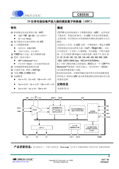
CS5530中文资料
GARMIN FAQ集锦

總共1133個img文件,若要作明細表,會很耗時,教你辦別的方法,來知道每個文件的經緯度範圍比較快:文件名稱的設定方式:30NNEEE0,N是緯度,E是經度,前30後0是俺版本代號,這都是一度四方範圍img文件。
例如:30290920即是:N29~N30&E029~E093的意思若用mapedit開啟img,在Map Properties內的Name,即有Be veg @ go green .save the planet_N29E092--西藏那要看你用何機型,若用OREGON 400T可以單獨將等高線合併成一個GMAPSUPP.img,然後複製到卡上使用,因為400T可多圖安裝使用。
若是60CSX則須與其他糾偏版詳圖合併成一個GMAPSUPP.img比較好。
這最主要依你自己需要及機子而定。
在分割地图时出现错误,Gmaptool自动退出(我是win7系统,在操作其它地图时没出现这个问题),大家有解吗我的程序是这样的,大家给下指导啊:1、合并venus750图和这个等高线图2、分割合并出来的图3、安装好MapSource地图4、合并Mapsource图,给60cx用-- by 会员ArBu (7/20/2010 12:58:21 PM) 你是以v enus750图和这个等高线图先合并成GMAPSUPP.img后,再分割取得安装文件,才装到MapSource上罢,暨然都装上MapSource了,就直接从MapSource输入到60CX即可,何必再合并呢?还有第一次合并成GMAPSUPP.img,也可以复制到60CX上来用阿。
只怕合并的设置不符手持机规定,无法显示或不正常。
所以俺是采取用从MapSource输入到60CSX,虽然传输速度是很慢,但安装到60CSX后运行很顺,显示也很正常。
请你参考看看谢谢wang的制作,下载了后,安装在MapSource里面,有很多“map created with ”,是不是有办法去除?以前看到过如下一个方法,不知对您有无帮助使用cGPSMapper產生的img檔後,以GPSMapEdit開啟後,將有"map created with "文字之POI的內容,將其前8碼記下,再使用UltraEdit以28000000替代,便可消除其文字部分。
赛米控丹佛斯 SEMITRANS IGBT模块 SKM400GB12T4 数据表

SEMITRANS ®3Fast IGBT4 ModulesSKM400GB12T4Features•IGBT4 = 4. generation fast trench IGBT (Infineon)•CAL4 = Soft switching 4. generation CAL-diode•Isolated copper baseplate using DBC technology (Direct Bonded Copper) •Increased power cycling capability •With integrated gate resistor•For higher switching frequenzies up to 20kHz•UL recognized, file no. E63532Typical Applications*•AC inverter drives •UPS•Electronic welders at fsw up to 20 kHzRemarks•Case temperature limited to T c = 125°C max.•Recommended T op = -40 ... +150°C •Product reliability results valid for T j = 150°CAbsolute Maximum Ratings SymbolConditions Values UnitIGBT V CES T j =25°C 1200V I C T j =175°CT c =25°C 616A T c =80°C474A I Cnom 400A I CRMI CRM = 3xI Cnom 1200A V GES -20...20V t psc V CC =800V V GE ≤ 15V V CES ≤ 1200VT j =150°C10µs T j-40...175°C Inverse diode I F T j =175°CT c =25°C 440A T c =80°C 329A I Fnom400A I FRM I FRM = 3xI Fnom1200A I FSM t p =10ms, sin 180°, T j =25°C1980A T j -40 (175)°C Module I t(RMS)T terminal =80°C500A T stg -40...125°C V isolAC sinus 50 Hz, t =1min4000VCharacteristics SymbolConditions min.typ.max.UnitIGBT V CE(sat)I C =400A V GE =15V chiplevel T j =25°C 1.80 2.05V T j =150°C 2.20 2.40V V CE0chiplevel T j =25°C 0.80.9V T j =150°C 0.70.8V r CE V GE =15V chiplevel T j =25°C 2.50 2.88m ΩT j =150°C3.754.00m ΩV GE(th)V GE =V CE , I C =15.2mA55.86.5V I CES V GE =0V V CE =1200V T j =25°C 5mA T j =150°C mA C ies V CE =25V V GE =0Vf =1MHz 24.6nF C oes f =1MHz 1.62nF C res f =1MHz1.38nF Q G V GE =- 8 V...+ 15 V 2260nC R Gint T j =25°C 1.9Ωt d(on)V CC =600V I C =400A V GE =±15V R G on =1ΩR G off =1Ωdi/dt on =9700A/µs di/dt off =4300A/µs T j =150°C 220ns t r T j =150°C 47ns E on T j =150°C 33mJ t d(off)T j =150°C 505ns t f T j =150°C 78ns E off T j =150°C 42mJ R th(j-c)per IGBT0.072K/WCharacteristics SymbolConditionsmin.typ.max.UnitInverse diodeV F = V EC I F =400AV GE =0V chiplevelT j =25°C 2.20 2.52V T j =150°C 2.15 2.47V V F0chiplevel T j =25°C 1.3 1.5V T j =150°C 0.9 1.1V r FchiplevelT j =25°C 2.3 2.5m ΩT j =150°C3.1 3.4m ΩI RRM I F =400A di/dt off =8800A/µs V GE =±15VV CC =600VT j =150°C 450A Q rr T j=150°C68µC E rr T j =150°C 30.5mJR th(j-c)per diode0.14K/W Module L CE 1520nH R CC'+EE'terminal-chip T C =25°C 0.25m ΩT C =125°C0.5m ΩR th(c-s)per module 0.020.038K/W M s to heat sink M635Nm M t to terminals M62.55Nm Nm w325gSEMITRANS ® 3Fast IGBT4 ModulesSKM400GB12T4Features•IGBT4 = 4. generation fast trench IGBT (Infineon)•CAL4 = Soft switching 4. generation CAL-diode•Isolated copper baseplate using DBC technology (Direct Bonded Copper) •Increased power cycling capability •With integrated gate resistor•For higher switching frequenzies up to 20kHz•UL recognized, file no. E63532Typical Applications*•AC inverter drives •UPS•Electronic welders at fsw up to 20 kHzRemarks•Case temperature limited to T c = 125°C max.•Recommended T op = -40 ... +150°C •Product reliability results valid for T j = 150°CFig. 1: Typ. output characteristic, inclusive R CC'+ EE'Fig. 2: Rated current vs. temperature I C = f (T C )Fig. 3: Typ. turn-on /-off energy = f (I C )Fig. 4: Typ. turn-on /-off energy = f (R G )Fig. 5: Typ. transfer characteristic Fig. 6: Typ. gate charge characteristicFig. 7: Typ. switching times vs. I C Fig. 8: Typ. switching times vs. gate resistor R GFig. 9: Transient thermal impedance Fig. 10: Typ. CAL diode forward charact., incl. R CC'+ EE'Fig. 11: CAL diode peak reverse recovery current Fig. 12: Typ. CAL diode peak reverse recovery chargeThis is an electrostatic discharge sensitive device (ESDS), international standard IEC 60747-1, Chapter IX* The specifications of our components may not be considered as an assurance of component characteristics. Components have to be tested for the respective application. Adjustments may be necessary. The use of SEMIKRON products in life support appliances and systems is subject to prior specification and written approval by SEMIKRON. We therefore strongly recommend prior consultation of our staff.。
美国红狮表中文说明书

美国红狮表中文说明书
PAX模拟量输入面板仪表具有较强的功能以适应宽范围的工业应用。
共有5中不同的型号分别处理不同的模拟量信号,包括直流电压电流,交流电压电流,过程量,温度和应变力。
请参考型号仪表的详细说明。
可选择的插入式功能卡为目前的应用提供丰富功能,同时为以后的产品升级提供了极为方便的条件。
PAX模拟量仪表具有5位14.2mm红色日光下可读或标准绿色的LED显示,并且显示亮度可以调节,保证无论在黑暗的空间还是在日光下,都可以读出数值。
同时具有最大值和最小值的峰值记忆功能,为了避免启动或非正常过程中捕捉到错误的峰值,此表的捕捉时间可以设定。
信号累加器可来计算某一时间的结果,这一结果被用来提供累加流量读数、电机和泵的工作间隔、选组称重等等。
指示符:
MAX一最大读数选择MIN一最小读数选择
TOT一累加读数选择,当累加值益处时闪烁SP1一设定点报警1触发SP2一设定点报警2触发SP3一设定点报警3触发SP4一设定点报警4触发
单位标签一可选工程单位标签,背光显示按键:共有5个按键,其中3个可编程功能键AD转换器:16位精度
更新率:
AD转换速率:20次1秒显示更新率: 1~20次1秒
设定点输出开l关延时:0~3275秒模拟量输出更新率:0~~10秒最大
1最小捕捉延时:0~3275秒。
广哈MAP交换机说明

广哈调度交换机说明MAP模块结构是根据用户要求来完成,分为冗余型和非冗余型(我厂为冗余型),MAP系统最多有896个端口。
非冗余系统要达到最大端口数需要4个模块,其中第一个模块(主控模块)为128端口。
而冗余系统要达到最大端口数则需要5个模块,因冗余型配备有两个主控模块。
MAP系统最少1个模块(带主控部分),128个用户;最多5个模块(冗余型两个主控部分),896个用户。
我厂MAP系统为冗余配置,模块内结构由两层机架组成,背部有背板。
上层机架为公共/接口模块,包括主控、用户、中继、服务板。
下层机架为告警、铃流、话路滤波、电源分配、交/直流转换。
各板件在机架中因作用、重要性不同,板件颜色不同,易于区分。
常用的有:红板,CPU板、冗余板、总线服务板;篮板,电话定时板(时钟)、会议和信号音板、时隙交换板、扫描及信号板;黑色板,模拟用户、中继板、各种服务板件(调度台接口板、以太网、来电显示等)。
常用电路板外观结构:板件正面有上、下两个插拔器。
1.上插拔器上标有一个6位数的代码,叫PN(Party Number),表示板的型号。
如763586.2.下插拔器上标有英文字母,是板的英文缩写,如ECPU。
一.板件介绍:1.公共控制板(红色,槽口1-5)ECPU 中央处理器板(1-3槽口)ECPU 负责处理呼叫控制、呼叫跟踪、呼叫过程及数据库管理。
配置为:处理器——奔腾233,内存——64M,数据位——32bit,主频——233MHz,版本要求——24版本以上,本身含磁盘装置。
RMU 冗余存储器(4槽口)用于存放已建立对话的端口的话音或数据信息,并把这些信息写到备用机架,保证备用机架处于热备用状态。
HCSU 高速C_总线服务板为呼叫处理器和电话控制设备之间提供通信接口。
2.电话控制板(蓝色,6-11槽口)TTU 电话定时板为系统提供时钟和同步信号,且是公共控制和电话控制子系统的接口点。
通过HCSU为CPU提供一个异步微处理器型的接口(R-总线)。
全能电子地图下载器用户手册

全能电⼦地图下载器⽤户⼿册全能电⼦地图下载器⽤户使⽤⼿册⼀、软件概述软件概述全能电⼦地图下载器,是⼀个专门下载地图⽡⽚数据的⼯具,可以从⾕歌地图、⾼德地图、腾讯地图、雅虎地图、必应地图、诺基亚地图、百度地图、天地图等⽹络地图中下载⽡⽚地图,并可⽆缝拼接成⼤图,是各居家旅⾏探险者的必备良伴。
她有以下特点:1.⽀持多线程⾼速下载(默认为10线程,最⼤⽀持20线程),线程数可由⽤户根据⾃⼰的⽹络带宽情况⾃⾏设置。
2.提供海量地图下载,下载图⽚数量⽆任何限制,如何你的硬盘够⼤,⽹络速度够快,可以把整个⽹络地图下载下来,除百度地图和天地图外,其他地图切⽚均可以⽤于⾕歌地图API调⽤,可轻松构建离线地图系统(百度地图需要⽤百度地图API)。
3.提供了全国主要城市边界坐标,内置了全国共有3000个县级⾏政区划单位边界坐标。
4.下载⽅式灵活多样,操作简单⽅便,只要拖动⼏下⿏标,就可按圆形,矩形,不规则多边形和⾏政区范围下载。
5.可⽆缝拼接单张⼤图,可拼接成BMP、PNG、JPG⼤图,最⼤⽀4G,GeoTIFF可拼接为⽆限制⼤图。
6.可⽣成精确坐标⽂件,可将所下载的图⽚精确地叠加到其它软件中,⽐如GlobalMapper。
7.可⾃动升级地图版本(仅⾕歌地图)8.⽀持下载完成后⾃动关机。
9.提供了地名搜索,坐标定位。
10.⽀持任务的断点续传,智能下载。
11.⽀持HTTP代理下载。
12.提供测量距离,测量⾯积,书签等⼈性化功能。
13.提供绿⾊版和安装版,均⽆需安装JA V A虚拟机或.NETFramework,⼩巧轻便,运⾏快速稳定。
⼆、⼆、下载地图下载地图2.1选择“图源”——⽐如:⾼德地图、⾕歌普通地图、⾕歌卫星图、⾕歌混合图、⾕歌地形图、腾讯普通地图,腾讯卫星图,腾讯混合图、雅虎中国地图全能电⼦地图下载器1、选择地图等级——⾕歌地图等级为0-19级,其他地是3-18级,地形图0-14级,建议下载区域遵循以下原则即可:世界1-4级,中国4-7级,城市8-17级。
布鲁克Quantax 400能谱仪说明

QUANTAX能谱仪用户手册Version 1.0目录系统简介 (3)1. QUANTAX硬件系统 (4)1.1 XFlash®系列探测器 (6)1.2 SVE系列信号处理器 (8)1.3 PC工作站 (11)2. QUANTAX软件系统 (12)2.1 软件登录 (13)2.2 主菜单介绍 (13)2.3 软件的基本功能介绍 (15)2.4 谱图采集的简易步骤与方法 (19)3. 显微分析基础知识 (28)3.1 粒子的相互作用 (29)3.2 连续X射线的产生 (Bremsstrahlung) (29)3.3 微分析中的激发空间和渗透深度 (30)3.4 辐射的能量计算 (30)3.5 临界能量 (31)4. 定性和定量方法 (33)5. 名词解释 (33)6. 常见用户疑问 (33)7. 参考书及资料 (33)系统简介QUANTAX是一种理想的多功能能量色散型微分析系统,广泛应用于工业、教育、科研等领域。
QUANTAX系统提供了不同的配置及各种选项以满足日益复杂的分析要求。
该系统可配置在扫描电子显微镜、透射电子显微镜、电子探针,以及双束FIB等分析仪器上。
所有的QUANTAX系统均可对体材料、薄膜材料、抛光样品、粗糙样品以及颗粒样品提供最先进的真正无标样定量分析。
该系统优化的自动或交互式图谱分析方法、先进的P/B-ZAF方法和精确全面的元素数据库确保无标样定量具有非常高的置信度。
此外,该系统还提供了基于PhiRhoZ的有标样定量分析选项包。
QUANTAX系统独特组合的有标样定量方法和无标样定量方法大大扩展了其分析能力。
QUANTAX系统直观的图形用户界面、灵活的项目管理组,以及不同风格报告的生成器是分析工作更为方便。
该软件可根据目的进行不同的设置以同时满足初学者和专家级用户的分析需求。
所有的QUANTAX系统均包含了一个在线帮助系统并且支持远程诊断和远程帮助。
本操作手册包含了基本的操作规程和简略的软件介绍,在线帮助系统及用户手册提供了更为详尽的资料。
- 1、下载文档前请自行甄别文档内容的完整性,平台不提供额外的编辑、内容补充、找答案等附加服务。
- 2、"仅部分预览"的文档,不可在线预览部分如存在完整性等问题,可反馈申请退款(可完整预览的文档不适用该条件!)。
- 3、如文档侵犯您的权益,请联系客服反馈,我们会尽快为您处理(人工客服工作时间:9:00-18:30)。
Features
•RoHS lead-solder-exempt compliant
•Automatic 115/230 input voltage selection
•All outputs fully regulated
•Remote sense, overvoltage protection, and
overtemperature protection
•Power Fail signal included
•Greater than 100,000 Hour MTBF
•U-Channel chassis: 8.50" x 4.50" x 2.00"
(215.9mm x 114.3mm x 50.8mm)
•Optional cover
•Metric and SAE mounting inserts
Multiple Output Model Selection– 130W Continuous Output Power
MODEL OUTPUT ADJUSTMENT OUTPUT PEAK CURRENT LINE LOAD TYPICAL RIPPLE &INITIAL SETTING VOLTAGE RANGE CURRENT(NOTE 1)REGULATION REGULATION NOISE %p-p (NOTE 2)ACCURACY
+5V 4.75V to 5.50V20A30A0.2%1%1% 5.1V to 5.2V
MAP130-4000+12V11.5V to 12.5V5A10A0.5%2%1%11.75V to 12.0V -5V Fixed1A1A0.5%2%1%-4.8V to -5.2V
-12V Fixed1A1A0.5%2%1%-11.6V to -12.4V
+5V 4.75V to 5.50V20A30A0.2%1%1% 5.1V to 5.2V
MAP130-4001+24V23.0V to 25.0V 3.5A5A0.5%2%1%23.9V to 24.1V -12V Fixed1A1A0.5%2%1%-11.6V to -12.4V
+12V Fixed1A1A0.5%2%1%-11.6V to -12.4V
+5V 4.75V to 5.50V20A30A0.2%1%1% 5.1V to 5.2V
MAP130-4002+12V11.5V to 12.5V5A10A0.5%2%1%11.9V to 12.1V -12V Fixed1A1A0.5%2%1%-11.6V to -12.4V
+12V Fixed1A1A0.5%2%
1%11.6V to 12.4V +5V 4.75V to 5.50V
20A30A1%1%1% 5.1V to 5.2V MAP130-4003+15V14.0V to 16.0V
4A8A1%2%1%15.0V to 15.1V -5V Fixed1A1A2%2%1%-4.8V to -5.2V
-15V Fixed1A1A2%2%1%-14.7V to -15.3V Power-One’s MAP130 Series of single and multiple output power supplies provide fully-regulated outputs with high peak current capabilities in a compact 4.50" x 8.50" x 2.00" U-channel chassis. Other standard features include autoselect AC input, EMI level B filtering, power fail, thermal shutdown (with warning), remote sense, and metric and SAE mounting inserts.
This convection-cooled series is designed for use in commercial and industrial environments in temperatures up to 50°C. All products are approved to the latest international regulatory standards and display the CE Mark. Description
Multiple Output Model Selection (Cont.)– 130W Continuous Output Power
MODEL OUTPUT ADJUSTMENT OUTPUT PEAK CURRENT LINE LOAD TYPICAL RIPPLE &INITIAL SETTING VOLTAGE RANGE CURRENT(NOTE 1)REGULATION REGULATION NOISE %p-p (NOTE 2)ACCURACY
+5V 4.75V to 5.50V20A30A0.2%1%1% 5.15V to 5.2V
MAP130-4004+24V23.0V to 25.0V 3.5A5A0.5%2%1%23.9V to 24.1V -15V Fixed1A1A0.5%2%1%-14.5V to -15.5V
+15V Fixed1A1A0.5%2%1%14.5V to 15.5V
+5V 4.75V to 5.50V20A30A0.2%1%1% 5.1V to 5.25V
MAP130-4010+12V11.5V to 12.8V5A10A0.5%2%1%11.75V to 12.0V -5V Fixed1A1A0.5%2%1%-4.8V to -5.2V
-12V Fixed3A3A0.5%2%1%-11.6V to -12.4V
+5V 4.75V to 5.50V20A30A0.2%1%1% 5.1V to 5.25V
MAP130-4020+12V11.5V to 12.8V5A10A0.5%2%1%11.75V to 12.0V -12V Fixed1A1A0.5%2%1%-11.6V to -12.4V
-5V Fixed3A3A0.5%2%1%-4.8V to -5.2V NOTES:1) Peak loads up to 165 Watts, (total of all outputs), for 60 seconds or less are acceptable, (10% duty cycle max.).
2) Maximum peak to peak noise expressed as a percentage of output voltage, 20MHz bandwidth.
OVERALL SIZE: 8.50" x 4.50" x 2.00" (215.9mm x 114.3mm x 50.8mm)
WEIGHT: 2.5 lb (1.13 kg)
NUCLEAR AND MEDICAL APPLICATIONS - Power-One products are not designed, intended for use in, or authorized for use as critical components in life support systems, equipment used in hazardous environments, or nuclear control systems without the express written consent of the respective divisional president of Power-One, Inc.
TECHNICAL REVISIONS - The appearance of products, including safety agency certifications pictured on labels, may change depending on the date manufactured. Specifications are subject to change without notice.。
