BAS16HT1中文资料
Belimo 产品B216 型号15 技术数据表说明书

B216•Stainless Steel Ball and StemType overviewType DNB21615Technical dataFunctional data Valve size0.5" [15]Fluid chilled or hot water, up to 60% glycolFluid Temp Range (water)0...250°F [-18...120°C]Body Pressure Rating600 psiClose-off pressure ∆ps200 psiFlow characteristic equal percentageServicing maintenance-freeFlow Pattern2-wayLeakage rate0% for A – ABControllable flow range75°Cv16No Characterized Disc TRUECv Flow Rating A-port: as stated in chart B-port: 70% of A – ABCvMaterials Valve body Nickel-plated brass bodyStem stainless steelStem seal EPDM (lubricated)Seat PTFECharacterized disc No Disc (full flow)Pipe connection NPT female endsO-ring EPDM (lubricated)Ball stainless steelSuitable actuators Non-Spring TRLRB(X)NRSpring TFRB(X)LFSafety notesWARNING: This product can expose you to lead which is known to the State of California tocause cancer and reproductive harm. For more information go to B216ApplicationMode of operationProduct featuresThis valve is typically used in air handling units on heating or cooling coils, and fan coil unit heating or cooling coils. Some other common applications include Unit Ventilators, VAV box re-heat coils and bypass loops. This valve is suitable for use in a hydronic system with variable flow.Flow/Mounting detailsTwo-way valves should be installed with thedisc upstream.Product featuresSY7~8 Replacement HandwheelDimensionsType DN B21615LRB, LRXAB C D E F H1H29.4" [239]2.4" [60]5.6" [141]5.0" [127]1.3" [33]1.3" [33]1.2" [30]1.1" [28]TRAB C D E F 3.7" [95]2.4" [60]5.2" [132]4.6" [117]1.3" [33]1.3" [33]B216TFRB, TFRXA B C D E F6.6" [167] 2.4" [60] 5.5" [139] 4.7" [120] 1.5" [39] 1.5" [39]LFA B C D E F7.9" [200] 2.4" [60] 6.1" [154] 5.5" [140] 1.3" [33] 1.3" [33]ARB N4, ARX N4, NRB N4, NRX N4A B C D E F11.4" [289] 2.4" [60]7.7" [196]7.0" [179] 3.1" [80] 3.1" [80]FootnotesNEMA 4X, Modulating Control, Non-Spring Return, 24 V, for DC 2...10 V or 4...20 mATechnical dataElectrical dataNominal voltageAC/DC 24 V Nominal voltage frequency 50/60 Hz Power consumption in operation 3.5 W Power consumption in rest position 0.6 WTransformer sizing 5 VA (class 2 power source)Electrical Connection Screw terminal (for 26 to 14 GA wire), 1/2" conduit connectorOverload Protectionelectronic throughout 0...95° rotation Functional dataOperating range Y 2...10 VOperating range Y note 4...20 mA w/ ZG-R01 (500 Ω, 1/4 W resistor)Input Impedance 100 kΩ for 2...10 V (0.1 mA), 500 Ω for 4...20 mA Position feedback U 2...10 V Position feedback U note Max. 1 mADirection of motion motor selectable with switch 0/1Manual override external push button Angle of rotation Max. 90°Angle of rotation note adjustable with mechanical stop Running Time (Motor)90 s / 90°Noise level, motor 45 dB(A)Position indicationpointer Safety dataDegree of protection IEC/EN IP66/67Degree of protection NEMA/UL NEMA 4XEnclosure UL Enclosure Type 4XAgency ListingcULus acc. to UL60730-1A/-2-14, CAN/CSA E60730-1:02, CE acc. to 2014/30/EU and 2014/35/EU Quality Standard ISO 9001Ambient temperature -22...122°F [-30...50°C]Ambient temperature note -40...50°C for actuator with integrated heating Storage temperature -40...176°F [-40...80°C]Ambient humidity Max. 100% RH Servicingmaintenance-freeMaterialsHousing material Die cast aluminium and plastic casing†Rated Impulse Voltage 800V, Type of action 1.AA, Control Pollution Degree 3AccessoriesElectrical accessories Description TypeBattery backup system, for non-spring return models NSV24 USBattery, 12 V, 1.2 Ah (two required)NSV-BATAuxiliary switch 1 x SPDT add-on S1AAuxiliary switch 2 x SPDT add-on S2AFeedback potentiometer 140 Ω add-on, grey P140A GRFeedback potentiometer 1 kΩ add-on, grey P1000A GRFeedback potentiometer 10 kΩ add-on, grey P10000A GRFeedback potentiometer 2.8 kΩ add-on, grey P2800A GRFeedback potentiometer 500 Ω add-on, grey P500A GRFeedback potentiometer 5 kΩ add-on, grey P5000A GR Electrical installationINSTALLATION NOTESProvide overload protection and disconnect as required.Actuators may be connected in parallel. Power consumption and input impedance must beobserved.Actuators may also be powered by DC 24 V.Only connect common to negative (-) leg of control circuits.A 500 Ω resistor (ZG-R01) converts the 4...20 mA control signal to 2...10 V.Actuators are provided with a numbered screw terminal strip instead of a cable.Meets cULus requirements without the need of an electrical ground connection.Warning! Live electrical components!During installation, testing, servicing and troubleshooting of this product, it may be necessaryto work with live electrical components. Have a qualified licensed electrician or other individualwho has been properly trained in handling live electrical components perform these tasks.Failure to follow all electrical safety precautions when exposed to live electrical componentscould result in death or serious injury.Wiring diagrams2...10 V / 4...20 mA ControlDimensions。
BAS16TT1资料

This document contains information on a new product. Specifications and information herein are subject to change without notice.
© Semiconductor Components Industries, LLC, 2000
元器件交易网
BAS16TT1
Advance Information Silicon Switching Diode
MAXIMUM RATINGS (TA = 25°C)
Rating Continuous Reverse Voltage Recurrent Peak Forward Current Peak Forward Surge Current Pulse Width = 10 ms Symbol VR IF IFM(surge) Max 75 200 500 Unit V mA mA 3 CATHODE 1 ANODE
BTA16中文资料_数据手册_参数
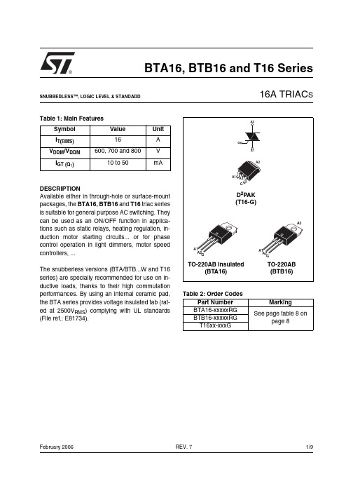
®1/9Table 1: Main FeaturesDESCRIPTIONAvailable either in through-hole or surface-mount packages, the BTA16, BTB16 and T16 triac series is suitable for general purpose AC switching. They can be used as an ON/OFF function in applica-tions such as static relays, heating regulation, in-duction motor starting circuits... or for phase control operation in light dimmers, motor speed controllers, ...The snubberless versions (BTA/BTB...W and T16series) are specially recommended for use on in-ductive loads, thanks to their high commutation performances. By using an internal ceramic pad,the BTA series provides voltage insulated tab (rat-ed at 2500V RMS ) complying with UL standards (File ref.: E81734).Symbol Value Unit I T(RMS)16A V DRM /V RRM 600, 700 and 800V I GT (Q 1)10 to 50mABTA16, BTB16 and T16 Series16A TRIAC SREV. 7February 2006SNUBBERLESS™, LOGIC LEVEL & STANDARDTable 2: Order CodesPart Number Marking BTA16-xxxxxRG See page table 8 onpage 8BTB16-xxxxxRG T16xx-xxxGBTA16, BTB16 and T16 Series2/9Table 3: Absolute Maximum Ratings Tables 4: Electrical Characteristics (T j = 25°C, unless otherwise specified)■SNUBBERLESS and Logic Level (3 quadrants)Symbol ParameterValue Unit I T(RMS)RMS on-state current (full sine wave)D 2PAK /TO-220AB T c = 100°C 16ATO-220AB Ins.T c = 15°C I TSM Non repetitive surge peak on-state current (full cycle, T j initial = 25°C) F = 50 Hz t = 20 ms 160A F = 60 Hz t = 16.7 ms168I ²t I ²t Value for fusingt p = 10 ms 144A ²s dI/dtCritical rate of rise of on-state cur-rent I G = 2 x I GT , t r ≤ 100 nsF = 120 HzT j = 125°C 50A/µs V DSM /V RSM Non repetitive surge peak off-state voltaget p = 10 msT j = 25°C V DSM /V RSM + 100V I GM Peak gate currentt p = 20 µsT j = 125°C 4A P G(AV)Average gate power dissipation T j = 125°C1W T stg T jStorage junction temperature range Operating junction temperature range- 40 to + 150- 40 to + 125°CSymbol Test ConditionsQuadrant T16BTA16 / BTB16Unit T1635SW CW BW I GT (1)V D = 12 V R L = 33 ΩI - II - III MAX.35103550mA V GT I - II - III MAX. 1.3V V GD V D = V DRM R L = 3.3 k ΩT j = 125°C I - II - IIIMIN.0.2V I H (2)I T = 500 mA MAX.35153550mA I L I G = 1.2 I GTI - III MAX.50255070mA II60306080dV/dt (2)V D = 67 %V DRM gate open T j = 125°C MIN.500405001000V/µs(dI/dt)c (2)(dV/dt)c = 0.1 V/µsT j = 125°C MIN.-8.5--A/ms(dV/dt)c = 10 V/µsT j = 125°C - 3.0--Without snubberT j = 125°C8.5-8.514BTA16, BTB16 and T16 Series3/9■Standard (4 quadrants)Table 5: Static Characteristics Table 6: Thermal resistance Symbol Test ConditionsQuadrant BTA16 / BTB16Unit C B I GT (1)V D = 12 V R L = 33 ΩI - II - III IV MAX.255050100mA V GT ALL MAX. 1.3V V GD V D = V DRM R L = 3.3 k Ω T j = 125°C ALLMIN.0.2V I H (2)I T = 500 mA MAX.2550mA I L I G = 1.2 I GTI - III - IVMAX.4060mA II 80120dV/dt (2)V D = 67 %V DRM gate openT j = 125°C MIN.200400V/µs (dV/dt)c (2)(dI/dt)c = 7 A/ms T j = 125°CMIN.510V/µsSymbol Test ConditionsValue Unit V T (2)I TM = 22.5 A t p = 380 µs T j = 25°C MAX. 1.55V V to (2)Threshold voltage T j = 125°C MAX.0.85V R d (2)Dynamic resistance T j = 125°C MAX.25m ΩI DRM I RRMV DRM = V RRMT j = 25°C MAX.5µA T j = 125°C2mANote 1: minimum I GT is guaranted at 5% of I GT max.Note 2: for both polarities of A2 referenced to A1.Symbol ParameterValue Unit R th(j-c)Junction to case (AC)D 2PAK / TO-220AB 1.2°C/WTO-220AB Insulated 2.1R th(j-a)Junction to ambient S = 1 cm ²D 2PAK45°C/WTO-220AB / TO-220AB Insulated60S = Copper surface under tab.BTA16, BTB16 and T16 Series4/9Figure 1: Maximum power dissipation versus RMS on-state current (full cycle)Figure 2: RMS on-state current versus case temperature (full cycle)Figure 3: RMS on-state current versus ambient temperature (printed circuit board FR4, copper thickness: 35µm) (full cycle)Figure 4: Relative variation of thermal impedance versus pulse durationFigure 5: On-state characteristics (maximum values)Figure 6: Surge peak on-state current versus number of cyclesBTA16, BTB16 and T16 Series5/9Figure 7: Non-repetitive surge peak on-state current for a sinusoidal pulse with width t p < 10 ms and corresponding value of I 2tFigure 8: Relative variation of gate trigger current, holding current and latching current versus junction temperature (typical values)Figure 9: Relative variation of critical rate of decrease of main current versus (dV/dt)c (typical values) (Snubberless & L ogic level types)Figure 10: Relative variation of critical rate of decrease of main current versus (dV/dt)c (typical values) (Standard types)Figure 11: D 2P AK Thermal resistance junction to ambient versus copper surface under tab (printed circuit board FR4, copper thickness: 35µm)BTA16, BTB16 and T16 Series6/9Figure 12: Ordering Information Scheme (BTA16 and BTB16 series)Figure 13: Ordering Information Scheme (T16 series)Table 7: Product SelectorPart Numbers Voltage (xxx)Sensitivity Type Package 600 V 700 V 800 V BTA/BTB16-xxxB X X X 50 mA Standard TO-220AB BTA/BTB16-xxxBW X X X 50 mA Snubberless TO-220AB BTA/BTB16-xxxCX X X 25 mA Standard TO-220AB BTA/BTB16-xxxCW X X X 35 mA Snubberless TO-220AB BTA/BTB16-xxxSW X XX 10 mA Logic level TO-220ABT1635-xxxGXX35 mASnubberlessD 2PAKBTB: non insulated TO-220AB packageBTA16, BTB16 and T16 Series Figure 14: D2PAK Package Mechanical DataFigure 15: D2PAK Foot Print Dimensions(in millimeters)7/9BTA16, BTB16 and T16 Series8/9In order to meet environmental requirements, ST offers these devices in ECOPACK® packages. These packages have a Lead-free second level interconnect . The category of second level interconnect is marked on the package and on the inner box label, in compliance with JEDEC Standard JESD97. The maximum ratings related to soldering conditions are also marked on the inner box label. ECOPACK is an ST trademark. ECOPACK specifications are available at: .Table 8: Ordering InformationOrdering type Marking Package Weight Base qtyDelivery modeBTA/BTB16-xxxyzRGBTA/BTB16xxxyz TO-220AB 2.3 g 50Tube T1635-xxxG T1635xxxG D 2PAK1.5 g50Tube T1635-xxxG-TRT1635xxxG1000Tape & reelNote: xxx = voltage, yy = sensitivity, z = typeTable 9: Revision HistoryDate Revision Description of ChangesOct-20026A Last update.13-Feb-20067TO-220AB delivery mode changed from bulk to tube.ECOPACK statement added.BTA16, BTB16 and T16 Series Information furnished is believed to be accurate and reliable. However, STMicroelectronics assumes no responsibility for the consequencesof use of such information nor for any infringement of patents or other rights of third parties which may result from its use. No license is granted by implication or otherwise under any patent or patent rights of STMicroelectronics. Specifications mentioned in this publication are subject to change without notice. This publication supersedes and replaces all information previously supplied. STMicroelectronics products are notauthorized for use as critical components in life support devices or systems without express written approval of STMicroelectronics.The ST logo is a registered trademark of STMicroelectronics.All other names are the property of their respective owners© 2006 STMicroelectronics - All rights reservedSTMicroelectronics group of companiesAustralia - Belgium - Brazil - Canada - China - Czech Republic - Finland - France - Germany - Hong Kong - India - Israel - Italy - Japan - Malaysia - Malta - Morocco - Singapore - Spain - Sweden - Switzerland - United Kingdom - United States of America9/9万联芯城-电子元器件采购网,提供一站式配套,解决物料烦恼,万联芯城是国内优质的电子元器件供应商,货源渠道来自原厂及代理商,只售原装现货,只需提交BOM物料清单,我们将为您报出一个满意的价格,解决客户采购烦恼,为客户节省采购成本,点击进入万联芯城。
BAS16H中文资料

105
IR (nA)
104
VR = 75 V
mga884
max 103
75 V
25 V 102
typ
typ 10
0
100
Tj (°C)
200
Fig 3. Reverse current as a function of junction temperature
1 10−2
10−1
1
10
tp (ms)
Max Unit
715 mV
855 mV
1
V
1.25 V
30 nA
1
µA
30 µA
50 µA
1.5 pF
4
ns
1.75 V
9397 750 14478
Product data sheet
Rev. 01 — 15 April 2005
© Koninklijke Philips Electronics N.V. 2005. All rights reserved.
元器件交易网
BAS16H
High-speed switching diode in SOD123F package
Rev. 01 — 15 April 2005
Product data sheet
1. Product profile
1.1 General description
100
0
0
1
VF (V)
2
(1) Tamb = 150 °C; typical values (2) Tamb = 25 °C; typical values (3) Tamb = 25 °C; maximum values
BAS16中文资料
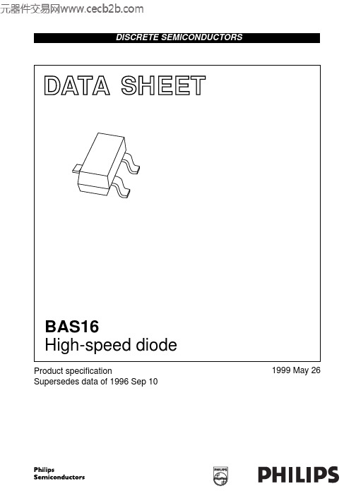
DATASHEETProduct specificationSupersedes data of 1996 Sep 101999May 26DISCRETE SEMICONDUCTORSBAS16High-speed diodebook, halfpageM3D088High-speed diodeBAS16FEATURES•Small plastic SMD package •High switching speed: max.4ns •Continuous reverse voltage:max.75V•Repetitive peak reverse voltage:max.85V•Repetitive peak forward current:max. 500mA.APPLICATIONS•High-speed switching in hybrid thick and thin-film circuits.DESCRIPTIONThe BAS16 is a high-speed switchingdiode fabricated in planar technology,and encapsulated in a small SOT23plastic SMD package.PINNINGPIN DESCRIPTION 1anode 2not connected 3cathodeFig.1 Simplified outline (SOT23) and symbol.Marking code: A6p =made in Hong Kong; A6t =made in Malaysia .handbook, halfpage 213MAM1852n.c.13LIMITING VALUESIn accordance with the Absolute Maximum Rating System (IEC 134).Note1.Device mounted on an FR4 printed-circuit board.SYMBOL PARAMETERCONDITIONSMIN.MAX.UNITV RRM repetitive peak reverse voltage −85V V R continuous reverse voltage −75V I F continuous forward current see Fig.2; note 1−215mA I FRM repetitive peak forward current −500mA I FSMnon-repetitive peak forward currentsquare wave; T j =25°C prior to surge; see Fig.4t =1µs −4A t =1ms −1A t =1s−0.5A P tot total power dissipation T amb =25°C; note 1−250mW T stg storage temperature −65+150°C T j junction temperature−150°CHigh-speed diodeBAS16ELECTRICAL CHARACTERISTICS T j =25°C unless otherwise specified.THERMAL CHARACTERISTICS Note1.Device mounted on an FR4 printed-circuit board.SYMBOL PARAMETERCONDITIONSMAX.UNIT V Fforward voltagesee Fig.3I F =1mA 715mV I F =10mA 855mV I F =50mA 1V I F =150mA1.25V I Rreverse currentsee Fig.5V R =25V 30nA V R =75V1µA V R =25V; T j =150°C 30µA V R =75V; T j =150°C50µA C d diode capacitance f =1MHz; V R =0; see Fig.61.5pF t rrreverse recovery timewhen switched from I F =10mA to I R =10mA; R L =100Ω; measured at I R =1mA; see Fig.74nsV frforward recovery voltage when switched from I F =10mA; t r =20ns;see Fig.81.75VSYMBOL PARAMETERCONDITIONSVALUE UNIT R th j-tp thermal resistance from junction to tie-point 330K/W R th j-a thermal resistance from junction to ambientnote 1500K/WHigh-speed diodeBAS16GRAPHICAL DATADevice mounted on an FR4 printed-circuit board.Fig.2Maximum permissible continuous forward current as a function of ambient temperature.0501002002500200MSA562 -115015010050I F (mA)T amb (o C)(1)T j =150°C; typical values.(2)T j =25°C; typical values.(3)T j =25°C; maximum values.Fig.3Forward current as a function of forward voltage.handbook, halfpage02300I F(mA)100200MBG3821V F (V)(1)(3)(2)Fig.4 Maximum permissible non-repetitive peak forward current as a function of pulse duration.Based on square wave currents.T j =25°C prior to surge.handbook, full pagewidthMBG70410t p (µs)1I FSM (A)10210−1104102103101High-speed diode BAS16Fig.5Reverse current as a function of junction temperature.10510410200MGA884100T ( C)jo I R (nA)10310275 V25 VtypmaxV = 75 V RtypFig.6Diode capacitance as a function of reverse voltage; typical values.f =1MHz; T j =25°C.handbook, halfpage08161240.80.60.40.2MBG446V R (V)C d (pF)High-speed diode BAS16Fig.7 Reverse recovery voltage test circuit and waveforms.(1)I R =1mA.handbook, full pagewidtht rr(1)I F toutput signalt rtt p10%90%V Rinput signal V = V I x R R F SR = 50SΩI FD.U.T.R = 50iΩSAMPLING OSCILLOSCOPEMGA881Fig.8 Forward recovery voltage test circuit and waveforms.t rtt p10%90%Iinputsignal R = 50SΩIR = 50iΩOSCILLOSCOPEΩ1 k Ω450 D.U.T.MGA882V frtoutput signalVHigh-speed diodeBAS16PACKAGE OUTLINEUNIT A 1max.b p c D E e 1H E L p Q w v REFERENCESOUTLINE VERSION EUROPEAN PROJECTIONISSUE DATE 97-02-28IECJEDECEIAJmm0.10.480.380.150.093.02.81.41.20.95e 1.92.52.10.550.450.10.2DIMENSIONS (mm are the original dimensions)0.450.15SOT23b pD e 1eAA 1L pQdetail XH EE w M v M ABAB 01 2 mmscaleA 1.10.9cX123Plastic surface mounted package; 3 leadsSOT23High-speed diode BAS16DEFINITIONSData Sheet StatusObjective specification This data sheet contains target or goal specifications for product development. Preliminary specification This data sheet contains preliminary data; supplementary data may be published later. Product specification This data sheet contains final product specifications.Limiting valuesLimiting values given are in accordance with the Absolute Maximum Rating System (IEC 134). Stress above one or more of the limiting values may cause permanent damage to the device. These are stress ratings only and operation of the device at these or at any other conditions above those given in the Characteristics sections of the specification is not implied. Exposure to limiting values for extended periods may affect device reliability.Application informationWhere application information is given, it is advisory and does not form part of the specification.LIFE SUPPORT APPLICATIONSThese products are not designed for use in life support appliances, devices, or systems where malfunction of these products can reasonably be expected to result in personal injury. Philips customers using or selling these products for use in such applications do so at their own risk and agree to fully indemnify Philips for any damages resulting from such improper use or sale.High-speed diode BAS16NOTESHigh-speed diode BAS16NOTESPhilips Semiconductors Product specification High-speed diode BAS16NOTES1999May2611© Philips Electronics N.V. SCA All rights are reserved. Reproduction in whole or in part is prohibited without the prior written consent of the copyright owner.The information presented in this document does not form part of any quotation or contract, is believed to be accurate and reliable and may be changed without notice. No liability will be accepted by the publisher for any consequence of its use. Publication thereof does not convey nor imply any license under patent- or other industrial or intellectual property rights.Internet: 199965Philips Semiconductors – a worldwide company Netherlands: Postbus 90050, 5600PB EINDHOVEN, Bldg.VB,Tel.+31402782785,Fax.+31402788399New Zealand: 2Wagener Place, C.P.O.Box 1041, AUCKLAND,Tel.+6498494160,Fax.+6498497811Norway: Box 1, Manglerud 0612, OSLO,Tel.+4722748000,Fax.+4722748341Pakistan: see Singapore Philippines: Philips Semiconductors Philippines Inc.,106Valero St.Salcedo Village, P.O.Box 2108MCC,MAKATI,Metro MANILA, Tel.+6328166380,Fax.+6328173474Poland: Ul.Lukiska 10, PL 04-123WARSZAWA,Tel.+48226122831,Fax.+48226122327Portugal: see Spain Romania: see Italy Russia: Philips Russia, atcheva 35A, 119048MOSCOW,Tel.+70957556918,Fax.+70957556919Singapore: Lorong 1, Toa Payoh, SINGAPORE 319762,Tel.+653502538,Fax.+652516500Slovakia: see Austria Slovenia: see Italy South Africa: S.A. PHILIPS Pty Ltd., 195-215Main Road Martindale,2092JOHANNESBURG, P.O.Box 58088 Newville 2114,Tel.+27114715401,Fax.+27114715398South America: Al.Vicente Pinzon,173, 6th floor,04547-130SÃO PAULO,SP, Brazil,Tel.+55118212333,Fax.+55118212382Spain: Balmes 22, 08007BARCELONA,Tel.+34933016312,Fax.+34933014107Sweden: Kottbygatan 7, Akalla, S-16485STOCKHOLM,Tel.+46859852000,Fax.+46859852745Switzerland: Allmendstrasse 140, CH-8027ZÜRICH,Tel.+4114882741Fax.+4114883263Taiwan: Philips Semiconductors, 6F, No.96, Chien Kuo N.Rd.,Sec.1,TAIPEI, Taiwan Tel.+886221342886,Fax.+886221342874Thailand: PHILIPS ELECTRONICS (THAILAND) Ltd.,209/2Sanpavuth-Bangna Road Prakanong, BANGKOK 10260,Tel.+6627454090,Fax.+6623980793Turkey: Yukari Dudullu, Org. San. Blg., 2.Cad. Nr. 28 81260Umraniye,ISTANBUL, Tel.+902165221500,Fax.+902165221813Ukraine : PHILIPS UKRAINE, 4Patrice Lumumba str., Building B, Floor 7,252042KIEV, Tel.+380442642776, Fax. +380442680461United Kingdom: Philips Semiconductors Ltd., 276Bath Road, Hayes,MIDDLESEX UB35BX, Tel.+441817305000,Fax.+441817548421United States: 811East Arques Avenue, SUNNYVALE, CA 94088-3409,Tel.+18002347381, Fax.+18009430087Uruguay: see South America Vietnam: see Singapore Yugoslavia: PHILIPS, Trg N. Pasica 5/v, 11000BEOGRAD,Tel.+38111625344,Fax.+38111635777For all other countries apply to: Philips Semiconductors,International Marketing &Sales Communications, Building BE-p, P.O.Box 218,5600MD EINDHOVEN, The Netherlands,Fax.+31402724825Argentina: see South AmericaAustralia: 34 Waterloo Road, NORTH RYDE, NSW 2113,Tel.+61298054455,Fax.+61298054466Austria:Computerstr. 6, A-1101 WIEN, P.O. Box 213,Tel.+431601011248, Fax.+431601011210Belarus: Hotel Minsk Business Center, Bld.3, r.1211, Volodarski Str.6,220050MINSK, Tel.+375172200733,Fax.+375172200773Belgium: see The NetherlandsBrazil:see South AmericaBulgaria:Philips Bulgaria Ltd., Energoproject, 15th floor,51James Bourchier Blvd., 1407SOFIA,Tel.+3592689211,Fax.+3592689102Canada: PHILIPS SEMICONDUCTORS/COMPONENTS,Tel.+18002347381, Fax.+18009430087China/Hong Kong: 501Hong Kong Industrial Technology Centre,72Tat Chee Avenue, Kowloon Tong, HONG KONG,Tel.+852********,Fax.+852********Colombia: see South AmericaCzech Republic: see AustriaDenmark: Sydhavnsgade 23, 1780COPENHAGEN V,Tel.+4533293333,Fax.+4533293905Finland: Sinikalliontie 3, FIN-02630ESPOO,Tel.+3589615800,Fax.+358961580920France: 51Rue Carnot, BP317, 92156SURESNES Cedex,Tel.+33140996161,Fax.+33140996427Germany: Hammerbrookstraße 69, D-20097HAMBURG,Tel.+4940235360,Fax.+494023536300Hungary:see AustriaIndia: Philips INDIA Ltd, Band Box Building, 2nd floor,254-D,Dr.Annie Besant Road, Worli, MUMBAI 400025,Tel.+91224938541,Fax.+91224930966Indonesia: PT Philips Development Corporation, Semiconductors Division,Gedung Philips, Jl. Buncit Raya Kav.99-100, JAKARTA 12510,Tel.+62217940040ext.2501, Fax.+62217940080Ireland: Newstead, Clonskeagh, DUBLIN 14,Tel.+35317640000,Fax.+35317640200Israel: RAPAC Electronics, 7Kehilat Saloniki St, PO Box 18053,TEL AVIV 61180, Tel.+97236450444,Fax.+97236491007Italy: PHILIPS SEMICONDUCTORS, Piazza IV Novembre 3,20124MILANO, Tel.+390267522531,Fax.+390267522557Japan: Philips Bldg 13-37, Kohnan 2-chome, Minato-ku,TOKYO 108-8507, Tel.+81337405130,Fax.+81337405057Korea: Philips House, 260-199Itaewon-dong, Yongsan-ku, SEOUL,Tel.+8227091412,Fax.+8227091415Malaysia: No.76Jalan Universiti, 46200PETALING JAYA, SELANGOR,Tel.+60 37505214,Fax.+6037574880Mexico: 5900Gateway East, Suite 200, EL PASO, TEXAS 79905,Tel.+9-58002347381, Fax +9-58009430087Middle East: see Italy Printed in The Netherlands 115002/03/pp12 Date of release: 1999May 26Document order number: 939775005878。
BAS16HT1G;中文规格书,Datasheet资料
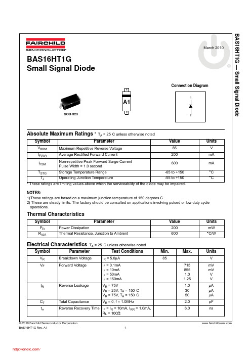
Absolute Maximum Ratings * T A = 25°C unless otherwise noted* These ratings are limiting values above which the serviceability of the diode may be impaired.NOTES:1)These ratings are based on a maximum junction temperature of 150 degrees C.2) These are steady limits. The factory should be consulted on applications involving pulsed or low duty cycle operations.Thermal CharacteristicsElectrical Characteristics T A = 25°C unless otherwise notedSymbolParameterValueUnitsV RRM Maximum Repetitive Reverse Voltage 85V I F(AV)Average Rectified Forward Current 200mA I FSM Non-repetitive Peak Forward Surge Current Pulse Width = 1.0 second 600mA T STG Storage Temperature Range -65 to +150°C T JOperating Junction Temperature-55 to +150°CSymbolParameter ValueUnitsP D Power Dissipation200mW R θJAThermal Resistance, Junction to Ambient600°C/WSymbolParameterTest ConditionsMin.Max.UnitsV R Breakdown Voltage I R = 5.0μA 85V V FForward VoltageI F = 0.1mA I F = 10mA I F = 50mA I F = 150mA7158551.01.25mV mV V V I RReverse LeakageV R = 75VV R = 25V, T A = 150°C V R = 75V, T A = 150°C 1.03050μA μA μA C T Total CapacitanceV R = 0, f = 1.0MHz2.0pF t rrReverse Recovery Time I F = I R = 10mA, I RR = 1.0mA,R L = 100Ω6.0ns2The following includes registered and unregistered trademarks and service marks, owned by Fairchild Semiconductor and/or its global subsidiaries, and is notAccuPower¥Auto-SPM¥Build it Now¥CorePLUS¥CorePOWER¥CROSSVOLT¥CTL¥Current Transfer Logic¥DEUXPEED®Dual Cool™ EcoSPARK®EfficientMax¥®Fairchild®Fairchild Semiconductor®FACT Quiet Series¥FACT®FAST®FastvCore¥FETBench¥FlashWriter®*FPS¥F-PFS¥FRFETGlobal Power Resource SMGreen FPS¥Green FPS¥ e-Series¥G max¥GTO¥IntelliMAX¥ISOPLANAR¥MegaBuck¥MICROCOUPLER¥MicroFET¥MicroPak¥MicroPak2¥MillerDrive¥MotionMax¥Motion-SPM¥OptoHiT™OPTOLOGIC®OPTOPLANAR®®PDP SPM™Power-SPM¥PowerTrenchPowerXS™Programmable Active Droop¥QFET®QS¥Quiet Series¥RapidConfigure¥¥Saving our world, 1mW/W/kW at a time™SignalWise¥SmartMax¥SMART START¥SPM®STEALTH¥SuperFET¥SuperSOT¥-3SuperSOT¥-6SuperSOT¥-8SupreMOS¥SyncFET¥Sync-Lock™®*The Power FranchiseTinyBoost¥TinyBuck¥TinyCalc¥TinyLogic®TINYOPTO¥TinyPower¥TinyPWM¥TinyWire¥TriFault Detect¥TRUECURRENT¥*P SerDes¥UHC®Ultra FRFET¥UniFET¥VCX¥VisualMax¥XS™* Trademarks of System General Corporation, used under license by Fairchild Semiconductor.DISCLAIMERFAIRCHILD SEMICONDUCTOR RESERVES THE RIGHT TO MAKE CHANGES WITHOUT FURTHER NOTICE TO ANY PRODUCTS HEREIN TO IMPROVE RELIABILITY, FUNCTION, OR DESIGN. FAIRCHILD DOES NOT ASSUME ANY LIABILITY ARISING OUT OF THE APPLICATION OR USE OF ANY PRODUCT OR CIRCUIT DESCRIBED HEREIN; NEITHER DOES IT CONVEY ANY LICENSE UNDER ITS PATENT RIGHTS, NOR THE RIGHTS OF OTHERS. THESE SPECIFICATIONS DO NOT EXPAND THE TERMS OF FAIRCHILD’S WORLDWIDE TERMS AND CONDITIONS, SPECIFICALLY THE WARRANTY THEREIN, WHICH COVERS THESE PRODUCTS.LIFE SUPPORT POLICYFAIRCHILD’S PRODUCTS ARE NOT AUTHORIZED FOR USE AS CRITICAL COMPONENTS IN LIFE SUPPORT DEVICES OR SYSTEMS WITHOUT THE EXPRESS WRITTEN APPROVAL OF FAIRCHILD SEMICONDUCTOR CORPORATION.As used herein:1. Life support devices or systems are devices or systems which, (a) areintended for surgical implant into the body or (b) support or sustain life, and (c) whose failure to perform when properly used in accordance with instructions for use provided in the labeling, can be reasonably expected to result in a significant injury of the user. 2. A critical component in any component of a life support, device, orsystem whose failure to perform can be reasonably expected to cause the failure of the life support device or system, or to affect its safety or effectiveness.ANTI-COUNTERFEITING POLICYFairchild Semiconductor Corporation's Anti-Counterfeiting Policy. Fairchild's Anti-Counterfeiting Policy is also stated on our external website, , under Sales Support.Counterfeiting of semiconductor parts is a growing problem in the industry. All manufacturers of semiconductor products are experiencing counterfeiting of their parts. Customers who inadvertently purchase counterfeit parts experience many problems such as loss of brand reputation, substandard performance, failed applications, and increased cost of production and manufacturing delays. Fairchild is taking strong measures to protect ourselves and our customers from the proliferation of counterfeit parts. Fairchild strongly encourages customers to purchase Fairchild parts either directly from Fairchild or from Authorized Fairchild Distributors who are listed by country on our web page cited above. Products customers buy either from Fairchild directly or from Authorized Fairchild Distributors are genuine parts, have full traceability, meet Fairchild's quality standards for handling and storage and provide access to Fairchild's full range of up-to-date technical and product information. Fairchild and our Authorized Distributors will stand behind all warranties and will appropriately address any warranty issues that may arise. Fairchild will not provide any warranty coverage or other assistance for parts bought from Unauthorized Sources. Fairchild is committed to combat this global problem and encourage our customers to do their part in stopping this practice by buying direct or from authorized distributors.PRODUCT STATUS DEFINITIONSDefinition of TermsDatasheet Identification Product Status Definition分销商库存信息: FAIRCHILDBAS16HT1G。
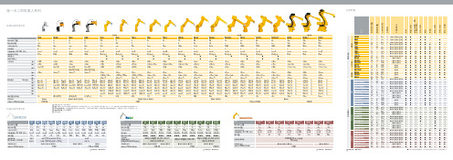
史陶比尔 机器人 (产品系列)
200 mm
200 mm (400 mm 可选)
200 mm (400 mm 可选)
±138°
±500° (4)
±500° (4)
±500° (4)
±270°
-
-
-
+133.5°/-120°
-
-
-
±270° (4)
350°/s 360°/s 350°/s 360°/s 290°/s 290°/s 287°/s 555°/s
±270° +130°/-110° ±270° (4) 130°/s 155°/s 115°/s 130°/s 135°/s 205°/s 190°/s 237°/s 200°/s 243°/s 297°/s 562°/s 726
CS8 或 CS8 M
RX170 HP 65 60 1835 6 ±0.04 IP65 (67)
l l
±180° ±120° ±145°
RX260 150 130 2831 6 ±0.07 IP65
±180° +75°/-55° +110°/-170°
±270°
±280°
+130°/-110°
±120°
±270° (4) 91°/s 57°/s
155°/s 130°/s
±2700° 108°/s (5) 104°/s (5)
手臂安装方式 史陶比尔CS8系列控制器
TX40 TX60 CR/ TX60 L TX90 TX90 L TX90 XL RX160 RX160 L RX130
CR
SCR CR/SCR CR/SCR CR/SCR CR/SCR CR
CR XL CR
2,3
乐泰各类胶粘剂型号及简介
乐泰各类胶粘剂型号及简介
乐
泰
瞬
干
胶
乐泰瞬干胶在工业上得到了最广泛的应用。乐泰瞬干胶涵盖了各种粘度,不同固化速度。充分适应各种充间隙及与被粘接材料。
乐泰系列瞬干胶包括增强型、低气味、无白化,对表面不敏感耐热型的产品。
380增强型
橡胶增强型,可粘接金属,橡胶及塑料,优良的抗剥离,冲击及剪切强度。
403低气味,低白化型
紫
外
线
固
化
胶
乐泰UV胶秉承其厌氧胶系列技术。使其产品从诞生就展现了卓越的适用性。广泛应用于工业,电子的粘接,固定,密封。
349通用型
紫外线固化,中粘度ຫໍສະໝຸດ 适合粘接玻璃和金属352通用型
高粘度,坚韧柔性,耐冲击及振动,粘接材料广泛,可使用紫外线或活化剂,或两者同时使用。使用紫外线时,在几秒钟内固化
3491通用型
460低气味,低白化型
·无白化,低粘度,低气味。粘接后零件洁净无玷污。
480橡胶增强型黑色
中等粘度,耐冲击,耐振动,耐剥离及耐热性能优良。
495塑料粘接型
通用型,中低粘度。用于粘接橡胶、金属和塑料件。能填充的间隙。
496金属粘接型
中粘度、初固迅速。用于粘接金属。
498耐热循环
中粘度、耐高温产品,适用于所有金属、大部分的塑料和橡胶。耐连续106°C高温和120°C间歇高温。
·快速固化,可用于惰性表面,容油性好。易拆卸,可在轻微油质的工作表面使用。用于乐泰预涂剂Dir-Loc螺栓拆装后重装时锁固。可用于M20以下螺纹的锁固与密封。
262高强度
·适用于大多数金属表面。触变性黏度,耐化学性好。用于M20以下螺纹的锁固与密封。是一种永久锁固的螺纹锁固剂,在极端的化学/环境条件下有优良的防锈及耐腐蚀性能。
伊顿断路器

-
SPC-E-130
SPC-E-280
SPC-E-335
SPC-E-385
SPC-E-460 SPC-E-580 SPC-EH-280 SPC-E-N/PE
插拔式
-
-
SPC-65/385 SPC-65/385/2 SPC-65/385/3 SPC-65/385/4 SPC-65/385/1N SPC-65/385/3P+N
型号说明?伊顿丰富的产品线?低压配电?空气断路器?塑壳断路器?低压终端配电产品?低压控制产品?电动机起动和保护产品?驱动产品?主令控制产品?工业自动化产品?2011eatoncorporation
伊顿低压配电产品型号说明
亚太区低压市场部
© 2011 Eaton Corporation. All rights reserved.
运最行大电持压续Uc
型号 固定式
额定(放k电A)电流In (8/20) µs
35
440
SPI-35/440
120
B 50
260
SPI-50/NPE
80
100
260
SPI-100/NPE
-
B+C
12.5
280
SPB-12/280
65
20
C
-
-
-
25
30
光D伏
-
-
-
-
-
10 40
运最行大电持压续Uc
385
极数: 1:1极 2:4极 3:3极 4:4极
© 2011 Eaton Corporation. All rights reserved.
14
14
Xpole-漏电断路器
BAS16HT1G;BAS16HT3G;BAS16HT1;中文规格书,Datasheet资料

STYLE 1: PIN 1. CATHODE (POLARITY BAND) 2. ANODE
0.63 0.025
1.60 0.063 2.85 0.112
0.83 0.033
*For additional information on our Pb−Free strategy and soldering details, please download the ON Semiconductor Soldering and Mounting Techniques Reference Manual, SOLDERRM/D.
nor the rights of others. SCILLC products are not designed, intended, or authorized for use as components in systems intended for surgical implant into the body, or other applications
†For information on tape and reel specifications, including part orientation and tape sizes, please refer to our Tape and Reel Packaging Specifications Brochure, BRD8011/D.
ISSUE H
b
C
NOTE 3
HE D
1
2
E
L
NOTE 5
A1
NOTES: 1. DIMENSIONING AND TOLERANCING PER ANSI Y14.5M, 1982. 2. CONTROLLING DIMENSION: MILLIMETERS. 3. LEAD THICKNESS SPECIFIED PER L/F DRAWING WITH SOLDER PLATING. 4. DIMENSIONS A AND B DO NOT INCLUDE MOLD FLASH, PROTRUSIONS OR GATE BURRS. 5. DIMENSION L IS MEASURED FROM END OF RADIUS.
道依茨产品介绍1016
DEUTZ柴油机项目是一汽集团公司引进德国道依茨公司产品技术的重点项目,总
投资123693万元人民币,一期生产纲领5万台发动机,2006年4月末实现批量生产。
缸体生产线 缸盖生产线 联合厂房
主 要 投 资 内 容
凸轮轴生产线
装配、试验生产线
在大连开发区 绿地建厂
新 建
联合动力站房 污水处理站 供油站 食堂
7
DEUTZ产品研发体系
严格执行了DEUTZ公司SE 0163 5001“发动机技术认可标准”、 DEUTZ公司SE 0163 5002“零件技术认可标准”
性能和材料复验 全尺寸检验 样件状态认可 功能试验(气道试验) 结构强度试验(曲轴) 零件耐久性试验(水泵) 公差试验(油嘴的流量值) 发动机性能试验 10台8~10万公里道路试验 整 机 耐 久 试 验 2台10000次热冲击试验 国 产 化 技 术 认 可 2台1000h全负荷耐久性试验
9
产品投产计划
序 号 1 2 3 4 5 6 7 8 9 10 11 12 13 14 15 16 17 18 19 20 21 22 23 24 25 26 型号 4/2012 4/2012 4/2012 4/2012 4/2012 4/2012 6/2012 6/2012 6/2012 6/2012 6/2012 4/1013 4/1013 4/1013 4/1013 4/1013 4/1013 6/1013 6/1013 6/1013 6/1013 6/1013 6/1013 6/1013 6/1013 6/1013 额定 功率 120 130 140 120 130 140 200 210 180 200 210 160 170 180 160 180 190 220 240 260 280 220 240 260 280 300 额定 转速 2500 2500 2500 2500 2500 2500 2500 2500 2500 2500 2500 2300 2300 2300 2300 2300 2300 2300 2300 2300 2300 2300 2300 2300 2300 2300 最大 扭矩 415 480 530 415 480 530 743 825 735 743 825 580 620 650 580 650 700 780 850 100 生产准备机型进展 扭矩 排 生产准备状态 转速 放 1500 欧2 开发中 1500 欧2 开发中 1500 欧2 开发中 1500 欧3 开发中 1500 欧3 开发中 1500 欧3 开发中 1500 欧2 开发中 1500 欧2 开发中 1500 欧2 开发中 1500 欧3 开发中 1500 欧3 开发中 1400 欧2 完成 1400 欧2 完成 1400 欧2 完成 1400 欧3 完成 1400 欧3 完成 1400 欧3 完成 1400 欧2 完成 1400 欧2 完成 1400 欧2 完成 1400 欧2 完成 1400 欧3 完成 1400 欧3 完成 1400 欧3 完成 1400 欧3 完成 1400 欧3 完成 投产计划 产品开发基础机 06-6-30 型 BF4M2012-12 BF4M2012-13 BF4M2012-14 BF4M2012-12E3 BF4M2012-13E3 BF4M2012-14E3 BF6M2012-20 BF6M2012-21 BF6M2012-18E3 BF6M2012-20E3 BF6M2012-21E3 BF4M1013-16 BF4M1013-17 BF4M1013-18 BF4M1013-16E3 BF4M1013-18E3 BF4M1013-19E3 BF6M1013-22 V BF6M1013-24 V BF6M1013-26 V BF6M1013-28 V BF6M1013-22E3 BF6M1013-24E3 BF6M1013-26E3 BF6M1013-28E3 BF6M1013-30E3 06-7-31 07-3-1 V V V V V V V V V V V V V V V V V
德国撒斯特模具钢

德国钢号模具钢冷作模具钢1.2080模具钢冷作模具钢详细介绍:是高碳高铬型冷作模具钢的代表钢号之一。
含有极高量(质量分数)的C 2.00%~2.30%和Cr11.00%~13.00%,是属于莱氏体钢,所以有很高的淬透性、淬硬性和耐磨性,淬火变形小,但当碳化物不均匀时,变形量多向性且不规则,它的组织不良是其主要缺点。
不均匀的碳化物很难用热处理方法改善,除非改用粉末冶金法制造。
抗冲击韧度差,导热性和高温塑性也差,热加工时要注意加热和锻造工艺。
该模具钢也是国际通用的冷作模具钢之一,但近来逐渐被更优秀的钢种如Cr12MoV、Cr12Mo1V1或基体钢所取代。
该模具钢自前苏联的X12引进,1957年时即已纳入标准(YB-1957)。
国外同类型的钢号有210Cr 12(ISO),日本的SKD1(JIS),大同特钢的DC1、日立金属的CRD,奥地利百禄公司的K100,瑞典的SVERER3(UHB)等。
主要用于要求高耐磨受冲击负荷较小的冷冲模工作零件(凸模凹模)、冷挤压模的凹模等),由于具有明显的优点和缺点,使用受到一定限制。
相关产品:1.2346模具钢、1.3343模具钢、1.3243模具钢、1.3247模具钢、1.1210碳素结构钢、1.0037碳素结构钢、2080冷作模具钢、2346冷作模具钢、3343冷作模具钢、3243高速模具钢、3247高速模具钢、1210碳素结构钢、0037碳素结构钢、2080耐磨铬钢、2346耐磨高铬刚、3343韧性高速钢、3243高韧性高速钢、3247高鈷韧性模具钢、1210优质碳素结构钢、0037普通碳素结构钢、2080圆钢、2346圆钢、3343圆钢、3243圆钢、3247圆钢、1210圆钢、0037圆钢、2080板材、2346板材、3343板材、3243板材、3247板材、1210板材、0037板材、冷作模具钢2080冷作模具钢、冷作模具钢2346、高速模具钢3343、高速模具钢3243、高速模具钢3247、碳素结构钢1210、碳素结构钢0037X155CrVMo121模具钢德国模具钢材X155CrVMo12 冷作模具钢主要应用一含12%Cr的莱氏体钢一耐磨性高一尺寸稳定性好一钼和钒的添加增加了切削力和淬透性一抗压强度佳兼良好的韧性主要应用一高性能切割工具一滚筒剪切刀片和薄板剪切刀片一弯曲冲压机一木器加工工具;校正轧辊和翻边轧辊;切丝板牙键;冷作心轴;冷作连续挤压工具一利用带钢生产的导管或外轮廓的轧具一用于研磨性高的塑料件的生产化学成分C Si Mn P S Cr Mo V1.50-1.60 0.20-0.60 0.20-0.15 ≤0.030 ≤0.030 11.0-12.0 0.70-1.00 0.90-1.00物理性质热膨胀系数【10-6m/(m x K)】20-100°C 20-200°C 20-300°C 20-400°C 20-500°C 20-600°C 20-700°C10.5 11.0 11.0 11.5 12.0热传导性【W/(m x K)】20°C350°C 700°C16.7 20.5 24.2热处理段造软性退火淬硬回火1050-900°C 800-850°C 1020-1040°C 500-570°C出厂状态运用状态钢材结构软性退火硬度最大至225HB 58-62 HRC 菜马体结构超声检验ASTM A388一FBH max.6mm(1/4 inch)或者SEP 1921-testgroup3一class C,c或者按客户要求德国X165CrMoV12冷作模具钢特性:通用冷作模具钢(空冷淬硬钢)耐磨性良好出厂状态:退火≤255HB;主要成份%:C:1.5;Si :≤0.4;Mn:≤0.6;Cr:12.0;Mo:1.0;V:0.3;淬硬温度℃:1000-1050;冷却方式:空冷回火温度与硬度HRC: 200:61;300:58;400:59;500:60;600:50;主要用途:冲裁模、冷作成形模、冷拉模、成形轧辊、冲头X100CrMoV5德国模具钢 1.2363模具钢冷作模具钢X100CrMoV5概述特性及适用范围:X100CrMoV5冷作模具钢,是引进美国的A2钢,在A类空淬钢中是用途最广的一种。
伊顿马达样本

● 97 [ 5.9]
● 120 [ 7.3]
● 146 [ 8.9]
● 159 [ 9.7]
● 185 [11.3]
● 231 [14.1]
● 293 [17.9]
● 370 [22.6]
安装法兰
● 2 螺栓 (标准),支口直径 82,6 [3.25],安装孔径 13,59 [.535],孔分布圆直径 106,2 [4.18] B.C.
hs和t系列马达输出轴密封hs和t系列马达防腐蚀涂层hs和t系列马达速度传感器hs和t系列马达转动轻松的定转子低速阀配流hs和t马达均可供选择h系列s系列t系列技术指标见p8见p14见p20性能参数91115172125尺寸产品安装尺寸输出轴接口121826输出轴的径向载荷能力29输出轴尺寸3031安装尺寸工具3233壳体压力及泄油口3435131927产品号标准的推荐的液压油36其他所有资料请与伊顿公司代理商联系产品目录内容油口尺寸3334373839型号规格编码特殊订货hs和t系列马达带有低速配流阀的技术指标和产品号28轴的转向标准的121826轴的转向与标准相反的373839速度传感器3529303132333435363334282930313233343536333428358通用马达h系列技术指标连续不连续连续不连续最高转速rpm连续流量推荐的过滤精度据iso清洁度1813技术指
● 直径 1 英寸,直轴,月牙键,端部有 1/4-20 的螺纹孔 ● 直径 1 英寸,SAE 6B 花键,端部有 1/4-20 的螺纹孔 ● 直径 1 英寸,直轴,有- 7,9 [.31] 的垂直通孔,离端面 11,2 [.44] ● 直径 1 英寸,直轴,有- 10,2 [.40] 的垂直通孔,离轴端 15,7 [.62],端部还有一个 1/4-20 的螺纹孔 ● 直径 7/8 英寸,SAE B 13 T 花键 ● 直径 7/8 英寸,SAE B 直轴有方键 ● 直径 1 英寸,锥轴,月牙键,带螺母 ● 直径 25mm,直轴,8mm 平键,端部有 M8 x 1,2 螺纹孔 ● 直径 1 英寸,直轴,月牙键,端部 1/4-20 螺纹孔 (有防腐蚀保护层) ● 直径 25mm,直轴, 8mm 平键,及 M8 x 1,2 螺纹孔 (有防腐蚀保护层) ● 直径 1 英寸,直轴有 10,2 [.40] 直径的垂直通孔,离端面 15,7 [.62] 并端部还有 1/4-20 的螺纹孔 (有防
美国T1钢、美国T4 钢钨系高速工具钢的特性

美国T1钢、美国T4 钢钨系高速工具钢的特性美国T1钢模具钢的特性,钨系高速工具钢,美国ASTM标准钢号。
该钢具有硬度,红硬性、耐磨性较好。
供货状态及硬度退火态,硬度 255HBS;冷拉态,硬度269HBS;冷拉态,退火硬度262HBS。
美国标准ASTM-A600-1999钢的化学成分(质量分数,%)C 0.65 ~0.80、Si 0.20~0.40、Mn 0.10~0.40、P≤0.030、S≤0.030、Cr 3.75~4.50、V 0.90~1.30、W 17.25~18.75。
参考对应钢号俄罗斯ГOCT标准钢号P18、德国DIN标准材料编号1.3355、德国DIN标准钢号S18-0-1、我国GB标准钢号W18Cr4V,英国BS标准钢号BT1、法国AFNOR标准钢号Z80WCV 18-04-01、意大利UNI标准钢号X75W18KU、西班牙UNE标准钢号HS18-0-1、日本JIS 标准钢号SKH2、美国AISI/SAE标准钢号T1、美国UNS标准钢号t12002、我国台湾CNS标准钢号SKH2、韩国KS标准钢号SKH2、国际标准化组织ISO标准钢号HS18-0-1。
淬火、回火规范预热温度815~875℃,淬火温度盐浴炉1175℃,可控气氛炉1288℃,回火温度550℃,回火后硬度≥63HRC。
典型应用举例适合具有红硬性要求的切削工具。
美国T4钢模具钢的特性,美国ASTM标准钨系含钴高速工具钢,是在W18Cr4V钢的基础上加入4.25%~5.75%(质量分数)的钴而成的。
因此,除了具有W18CrV4钢的性能外,由于加入了钴,提高了钢的高温硬度和红硬性,所以可在较高的温度下使用。
该钢不具有较高的韧性,且易磨削。
供货状态及硬度退火态,硬度269HBS,冷拉态,硬度285HBS,冷拉二退火,硬度277HBS。
标准ASTM A600-1999钢的化学成分(质量分数,%)C 0.70~0.80、Si 0.20~0.40、Mn 0.10~0.40、P≤0.030、S≤0.030、Cr 3.75~4.50、Mo 0.40~1.00、V 0.80~1.20、W 17.50~19.00、Co 4.25~5.75。
PureOptions KX White W 安全技术说明书

安全技术说明书页: 1/14 巴斯夫安全技术说明书按照GB/T 16483编制日期 / 本次修订: 27.12.2021版本: 2.0日期/上次修订: 22.09.2021上次版本: 1.0日期 / 首次编制: 22.09.2021产品: PureOptions™ KX White W(30662766/SDS_GEN_CN/ZH)印刷日期 17.10.20231. 化学品及企业标识PureOptions™ KX White W推荐用途: 仅用于工业用途, 制备颜料不推荐用途: 消费者公司:巴斯夫(中国)有限公司中国上海浦东江心沙路300号邮政编码 200137电话: +86 21 20391000传真号: +86 21 20394800E-mail地址: **********************紧急联络信息:巴斯夫紧急热线中心(中国)+86 21 5861-1199巴斯夫紧急热线中心(国际):电话: +49 180 2273-112Company:BASF (China) Co., Ltd.300 Jiang Xin Sha RoadPu Dong Shanghai 200137, CHINA Telephone: +86 21 20391000Telefax number: +86 21 20394800E-mail address: ********************** Emergency information:Emergency Call Center (China):+86 21 5861-1199International emergency number: Telephone: +49 180 2273-1122. 危险性概述纯物质和混合物的分类:皮肤致敏物: 分类1皮肤腐蚀/刺激: 分类3巴斯夫安全技术说明书日期 / 本次修订: 27.12.2021版本: 2.0产品: PureOptions™ KX White W(30662766/SDS_GEN_CN/ZH)印刷日期 17.10.2023严重损伤/刺激眼睛: 分类2A对水环境的急性危害: 分类3对水环境的慢性危害: 分类3标签要素和警示性说明:图形符号:警示词:警告危险性说明:H319造成严重眼刺激。
高标准严要求,争做行业领头人

34 食品安全导刊 2014年12月高标准严要求,争做行业领头人□ 王翠竹 本刊记者——访哈柏司工业传动设备(上海)有限公司行业销售主管侯远哲中国的经济正处于高速发展阶段,工业自动化水平的不断提高带动了食品饮料、农产品、电子、建材等行业的快速发展,给传动及输送带行业带来巨大的发展机遇。
国家着重强调生产安全、节能、环保、高强力的传输带,这样的产品也备受用户信赖。
因此,越来越多的传输带生产企业响应国家号召,注重研发新型环保节能的传输带产品。
现而今传输带以迅猛发展之势,迅速占领了输送市场。
在发展如此快速的背景下,生产企业若想长盛不衰,就需要掌握好发展方向。
而且随着经济的发展,科技的进步及自动化程度的提高,市场对传输带的需求也越来越大。
哈柏司工业传动设备(上海)有限公司(以下简称哈柏司)就是当下传输带企业中的佼佼者。
因为专业,所以更加努力H a ba sit (中文译名︰哈伯斯特®)集团是一家瑞士私营企业,成立于1946年,最初以动力传动平面皮带起家,目前在全球拥有17家工厂。
哈柏司工业传动设备(上海)有限公司成立于2004年,位于上海市松江区,隶属于Habasit (哈伯斯特®)集团瑞士总公司,提供的产品有传动皮带、输送皮带、圆带、塑料模组式网带、机械带、锭带、无缝皮带、不织布输送带、耐高温带、印花导带、PU齿形带、各式特殊带、加工工具以及耐磨导轨等。
哈柏司主要负责Habasit (哈伯斯特®)产品在中国大陆市场的推广、销售、加工及服务,为客户提供输送、传动应用方面的解决方案。
啤酒饮料行业能够用到的Ha basit (哈伯斯特®)产品主要包括平面皮带、塑料模组式输送网带和顶板链传输带。
“目前中国市场中绝大多数传输带都在国内生产,而哈柏司的产品均由欧洲及美洲进口。
在欧洲我们所有的产品在推向市场前都经过严格测试,测试项目包括强度、耐用性、安全性、应用性、材料特性等各方面。
- 1、下载文档前请自行甄别文档内容的完整性,平台不提供额外的编辑、内容补充、找答案等附加服务。
- 2、"仅部分预览"的文档,不可在线预览部分如存在完整性等问题,可反馈申请退款(可完整预览的文档不适用该条件!)。
- 3、如文档侵犯您的权益,请联系客服反馈,我们会尽快为您处理(人工客服工作时间:9:00-18:30)。
0.039(1.00) 0.031(0.80)
1. DIMENSIONING AND TOLERANCING PER ANSI Y14.5M, 1982. 2. CONTROLLING DIMENSION: MILLIMETERS. 3. LEAD THICKNESS SPECIFIED PER L/F DRAWING WITH SOLDER PLATING.
BAS16HT1
SURFACE MOUNT SWITCHING DIODE Reverse Breakdown Voltage - 75 Volts
SOD-urrent - 200mA
0.106(2.70) 0.091(2.30) 0.071(1.80) 0.063(1.60)
o
TA=85 C 0.1 TA=55 C 0.01
o o
o
1.0
TA=25 C
o
TA=25 C 0.1 0.2 0.001 0.4 0.6 0.8 1.0 1.2 0 10 20 30 40 50
VF, FORWARD VOLTAGE ( VOLTS )
VR, REVERSE VOLTAGE ( VOLTS )
o
SYMBOLS VR IF IFSM
VALUE 75 200 500
UNITS Vdc mAdc mAdc
THERMAL CHARACTERISTICS
CHARACTERISTIC Total Device Dissipation FR-5 Board, TA=25 C o Derate above 25 C Thermal Resistance Junction to Ambient Junction and Storage Temperature
tr 10%
tp
T
Notes: 1. A 2.0k variable resistor adjusted for a Forward Current (IF) of 10mA. 2. Input pulse is adjusted so IR(peak) is equal to 10mA. 3. tp » trr
FIGURE 4. CAPACITANCE
0.68
CD, DIODE CAPACITANCE ( pF )
0.64
0.60
0.56
0.52 0 2 4 6 8
VR, REVERSE VOLTAGE ( VOLTS )
REV. : 0
Zowie Technology Corporation
o
o
SYMBOLS PD R
JA
MAX. 200 1.57 635 150
UNITS mW o mW / C
o
C/W
o
TJ, TSTG
C
ELECTRICAL CHARACTERISTICS ( TA=25 C unless otherwise noted )
CHARACTERISTIC ( VR=75Vdc ) o ( VR=75Vdc, TJ=150 C ) o ( VR=25Vdc, TJ=150 C ) ( IBR=100uAdc ) ( IF=1.0mAdc ) ( IF=10mAdc ) ( IF=50mAdc ) ( IF=150mAdc ) ( VR=0, f=1.0MHz ) ( IF=10mAdc, tr=20nS ) ( IF=IR=10mAdc, RL=50 ) ) SYMBOLS MIN. 75 MAX. 1.0 50 30 0.72 0.86 1.00 1.25 2.0 1.75 6.0 45 UNITS
Reverse Voltage Leakage Current Reverse Breakdown Voltage
IR V( BR )
uAdc Vdc
Forward Voltage
VF
Vdc
Junction Capacitance Forward Recovery Voltage Reverse Recovery Time Stored Charge
FIGURE 2. FORWARD VOLTAGE
100 10
FIGURE 3. LEAKAGE CURRENT
TA=150 C
o
IF, FORWARD CURRENT ( mA )
IR, REVERSE CURRENT ( uA )
TA=85 C 10 TA= -40 C
o
o
TA=125 C 1.0
Device Marking : BAS16HT1 = A6
*Dimensions in inches and (millimeters)
MAXIMUM RATINGS
Ratings at 25 C ambient temperature unless otherwise specified. Continuous Reverse Voltage Peak Forward Current Peak Forward Surge Current
1 2
1 CATHODE
0.016(0.40) 0.010(0.25)
0.053(1.35) 0.045(1.15) 0.006(0.150) REF. 0.025(0.63) 0.033(0.83) 0.063(1.60) 0.112(2.85)
NOTE 3 0.007(0.18) 0.004(0.09) NOTES: 0.004(0.10) 0.000(0.00)
CJ VFR trr QS
pF Vdc nS pC
( IF=10mAdc, to VR=5.0Vdc, RL=500
REV. : 0
Zowie Technology Corporation
RATINGS AND CHARACTERISTIC CURVES OF BAS16HT1
FIGURE 1. RECOVERY TIME EQUIVALENT TEST CIRCUIT 820 +10 V 2k 100uH 0.1uF D.U.T. OUTPUT PULSE GENERATOR 50 50 INPUT SAMPLING OSCILLOSCOPE 90% VR INPUT SIGNAL IR iR(REC) = 1mA OUTPUT PULSE (I F = I R = 10 mA; measured at iR(REC) = 1mA IF 0.1uF IF trr T
