ESR100M1C000B中文资料
液晶杜邦17011电源电源测试系统说明书

EthernetMODEL 17011KEY FEATURESHigh precision output and measurement up to 0.015% of full scaleFast current response up to <100 µS High sampling rate up to 10 mS Flexible sampling recording ( t, V , I, Q, E)Channel parallel output function with maximum 1200A outputHigh efficiency charge and discharge with low heatingEnergy recycling during discharge (AC/DC bi-directional regenerative series) Waveform simulation function (current/power mode) Built-in DCIR test functionBuilt-in EDLC capacitance and DCR test functionOperating modes: CC / CP / CV / CR / CC-CV / CP-CV / Rest / SD test Multi-level safety protection mechanism Integrable data logger and chamberAPPLICATIONSElectric vehicle Electric scooter/bike Energy storage system Power toolsQuality inspection agency The Chroma 17011 Battery Cell Charge and D ischarge Test System is a high precision system designed specifically for testing lithium-ion battery (LIB) cells, electrical double layer capacitors (ED LC), and lithium-ion capacitors (LIC). It is suitable for product development, quality control, and is helpful program editing and test results analysis much easier.The Chroma 17011 test system has flexible software editing functions embedded that can create basic charging/discharging or complex cycle tests for each channel to run BATTERY CELL CHARGE & DISCHARGETEST SYSTEM MODEL 17011P r o vided b vided by y : com (800)40404-A -ATE TEC CAd Advanced vanced T Test estE quipment Rentals®High precision – improving product qualityVoltage / current measurement accuracy: 0.015 of F.S. / 0.02 of F.S.Wide range of voltage output: Equipped with a 0V to 6V output range, and specific models allow to switch between three built-in voltage output modes. Voltage measurements distinguished up to 0.1mV.Multiple range measurement design: Providing various current or voltage ranges (depending on the model) to greatly improve measurement accuracy and resolution. The current range switches automatically and at the constant voltage mode there is no current output interruption.Fast current response – suitable for a variety of high-speed transient test applicationsCurrent response time (10% to 90%) < 100 µS *1Support dynamic waveform to simulate the rapid changing current and power states*1: The current response time <100 µS applies to model 17216M-10-6, the impedance of other UUTswill slightly differ.Rise Time<100 µS (17216M-10-6)Rise Time<250 µS (17208M-6-30)Model 17216M-10-6Model 17216M-6-12Model 17208M-6-30Model 17208M-6-60Multi-Voltage Range (17216M-10-6)Multi-Current RangeLoading waveform currentDynamic waveform simulation Dynamic waveform simulationCurrent and power dynamic charge/discharge waveform, simulate the actual battery usage of car driving or other real life applicationsImport the current and power waveforms from Excel fileSave 1,440,000 points in each channel for long hour dynamic testingMinimalize time interval for data output: 10 mS*1: 17216M-10-6 has three built-in voltage output modes that can be switched through the software settings.*2: 17208M-6-60 has to be paired with an external power supply and placed into a rack; other models contain an integrated power module and can beused either stand-alone or in a rack.Rise time < 5 mSEnergy recycling – optimal utilization of electricityDirect recycling: Automatically transfer the discharging energy to the battery cells to be charged with recycling efficiency >80% Grid recycling: Recycle the excessiveenergy to the grid with recyclingefficiency >60%Low carbon emissions for green energy,preventing waste heat from generatingduring dischargeSaving electricity costs with highefficiency power charge and dischargeSaving air conditioning costs on coolingequipmentCurrent harmonic distortion <5%for feedback to grid currentPower factor >0.98 at rated powerHigh precision – improving product qualityVoltage accuracy: (0.02% of Reading + 0.02% of F.S.)Current accuracy: 0.05% of F.S.Fast current response – waveform modeCurrent response speed (10% to 90%) < 5 mS applicablefor all kinds of testsSupport dynamic waveform to simulate the current and power stateof actual car driving with NEDC, FUDS and DST test standardsAC/DCChroma 17212M-6-100Chroma A691104Direct RegenerationAC/DC* A fitting AC/DC bi-directional converter is chosen according to the power input and placed into a rack.Flexible paralleling channels for outputT h e t e s t s y s t e m s a l l o w f l e x i b l e s e t t i n g f o for various UUTs.which supports full range of productsSuitable for high ratio charge and discharge test or diversified battery test applicationsData protection and recoveryPower loss data restoring mechanism: After a power loss, the PC will automatically recover the data status of the testingdata that already was written into the database. The user can choose to resume or restart testing.High frequency sampling measurement technology – improving measurement accuracyV / I sampling rate: 50 KHz (∆t 20 µS)Generally, battery testers use software to read current values for calculating power; however, limited data sampling rates could result in large errors when calculating the dynamic current capacity. By increasing the sampling rate and using a double integration method, Chroma 17011 is able to provide a capacity calculation with much higher accuracy. When the current changes, the data is not lost and the transmission speed is not affected.* Note: The current response time <100 µS applies to model 17216M-10-6, the impedance of other UUTs will slightly differ.General charger/discharger sampling rateChroma charge & discharge tester sampling rateHPPC TestHPPC test applicationHPPC is a test procedure developed by the USABC (U.S. Advanced Battery Consortium) for the battery power performance of hybrid and electric vehicles. Within the batteries operation voltage range, the procedure mainly establishes the function of the relationship between the depth of discharge and power and, secondarily, establishes the depth of discharge, conductive resistance and polarization resistance function via the voltage and current response curve from discharging, standing to charging. The measured resistance can be used to assess the battery's power recession during later life tests and its equivalent circuit model development. Chroma 17011 has a flexible editing program that allows HPPC testing.DCIR test (2)DCIR test (1)Lumped parameter model circuit diagram Battery capacity test applicationT h e c a p a c i t y c a n b e o b t a i n e d a s t h e i n t e g r a l o f t h e c u r re n t integrating the current versus time from the start of charging/discharging until the cut-off condition is reached. The comparison results are useful to analyze performance differences between products, and the common test items include current ratio and temperature characteristics tests. Higher accuracy of current, voltage measurement and faster sampling enable to distinguish more accurately the differences in battery cell capacity.Battery cycle life test applicationCycle life is one of the most important test items for batteries. In accordance with the experimental purpose, it tests the same battery through repeated charge and discharge conditions until the capacity falls to 80%, and calculates the cycle numbers. The cycle life test can be used to evaluate the battery performance or define the applicable conditions of use.Battery DCIR test applicationThe internal resistance value is related to the charge/discharge ratio of a battery. The larger the internal resistance value, the lower the efficiency when temperature rises. According to the lithium-ion battery equivalent circuit model, the ACIR measurement of traditional 1KHz LCR meters can only evaluate the conductive resistance (Ro) of the battery that affects the instantaneous power output, but is unable to evaluate the polarization resistance (Rp) produced during electrochemical reaction. The D CIR evaluation includes the ACIR that is closer to the actual polarization effect of battery under continuous power applications.The Chroma 17011 includes two types of D CIR test modes: DCIR test (1) calculates the DCIR value using the voltage difference caused by the change of one-step current, DCIR test (2) calculates the DCIR value using the voltage difference caused by the change of two-step current. Users can select the desired test mode and automatically, without any manual calculation, get the results that comply with IEC 61960 standards.CapacitydQ/dV vs voltageCoulombic efficiency test Incremental capacity analysis applicationThe high precision voltage measurement and V sampling function can draw dQ/dV versus voltage curve diagrams to analyze battery cell characteristics and capacity degradation.Coulombic efficiency test applicationCoulombic efficiency (CE) is calculated by the charge/discharge capacity ratio when the battery is fully charged and then fully discharged. Good batteries have higher coulombic efficiency, and need high precision and stable equipment to distinguish differences. An accurate coulombic efficiency test can estimate the batterylifespan with only a few cycles.EDLC capacitance (C) test applicationIn accordance with the Straight Line Approximation Method of the IEC 62391 testing standard, before measuring the capacitance (C) value, the ED LC first needs to be fully charged through a CC-CV charging mode. The capacity test is to discharge CC via the above discharge current. Then, the electric potential difference ( V) of two reference points on the discharge curve are taken against the time difference ( t) and the discharge current (I) to calculate the capacitance value of the EDLC.EDLC combined DCR and C test applicationChroma 17011 also has a direct current resistance (D CR) and capacitance (C) combined test application. Under the same CC-CV charged and CC discharged conditions, the user can use the electric potential in the chosen reference points to simultaneously calculate the DCR and C values of the EDLC to save testing time.The equivalent circuit model development of the classical EDLC includes an equivalent series resistance (ESR), a capacitance (C), and an equivalent parallel resistance (EPR). The ESR is used to evaluate the internal loss and heat of the EDLC during charging/discharging; the EPR to evaluate the leakage effect in the EDLC's long-term storage; the C to evaluate the EDLC cycle life.These parameters are not easily directly measured in a laboratory; researchers need data analysis and complex calculations to determine these important indicators. Chroma 17011 is equipped with the IEC 62391 testing standards and the user can use charge/discharge tests to obtain the ED LC parameters values, in order to evaluate the EDLC characteristics and cycle life.ED LC direct current resistance (D CR) and equivalent series resistance (ESR) test applicationChroma 17011 offers ED LC direct current resistance testing function compliant with test standard IEC 62391. Before testing, the ED LC has to be CV charged. The capacity test is to discharge CC via the above discharge current. When the discharge is completed, get the linear section on the discharge curve and extend it to discharge time and then get the voltage difference of rated voltage and discharge current to calculate the DCR value.EDLC equivalent circuit model developmentVoltage Characteristic Between EDLC TerminalsVoltage Characteristic Between EDLC TerminalsVoltage Characteristic Between EDLC TerminalsCharge/discharge performance and cycle life test applicationThe built-in direct current resistance (D CR) and capacitance (C) test modes can be combined with cycle function and variable set testing conditions to test the EDLC load endurance and reliability. After testing, the user can directly export DCR vs Cycle No. and Capacity vs Cycle No. reports to analyze the EDLC failure and deterioration mechanisms.Self-discharge test modeCoulombic efficiency testAutomatically change current range in CC-CV modeCharge-Discharge Rate Test Charge-Discharge Cycle TestingCoulombic efficiency test applicationChroma 17011 is equipped with low noise, automatically switching current range, and cut-off report as to quickly output accurate c u r re n t c h a rg e /d i s c h a rg e. T h e c o u l o m b i c e ff i c i e n c y (C E ) i s calculated by the charge/discharge capacity ratio, which indicates the ED LC internal capacity conversion as available capacity. A highly accurate CE is an important marker to distinguish differences between products.Leakage current test applicationED LC leakage current measurements generally need to CC-CV charging until a specific time and then it measures this tiny charging current, which is seen as leakage current. The Chroma 17011 CC-CV mode can automatically change current range without output interruption. Under stable voltage, the current range can be as small as 200µA.Current (A)Self-discharge test applicationChroma 17011 also has a built-in self-discharge test mode, when the ED LC is fully charged it can test the charge/discharge for a set time period. When this mode starts, the system will cut off the measuring circuit to provide the ideal open circuit and solely measure the starting potential (V1) and cut-off potential (V2). The software can automatically calculate the electric potential difference ( V).CE=Q Discharge / Q ChargeThe Chroma 17011 test systems are controlled by computer software with diverse functions for testing energy storage products. The safe, stable and friendly operation interface allows users to perform setting and testing rapidly.Support English, Traditional Chinese, and Simplified Chinese languages interfaces Real time multi-channel DUT status monitoringSecurity management: set user authority for safe managementFailure record tracking: independently record abnormalities for each channel, the charge and discharge protection will abort the testwhen an abnormal condition is detectedRecipe editing500 steps per recipeDouble loop (Cycle & Loop) with 999,999 repeat counts per loop Sub-recipe function: Call existing recipesTest steps : CC / CV / CP / CC-CV / CP-CV / CR / Rest / Waveform / DCIR / C / DCR, etc. Cut-off conditions : Time / Current / Capacity / Power / Variable, etc. Logical operations : Next / End / Jump / If-Then Recipe executingOperating modes: Start / Stop / Pause / Resume / Jump / Reserve Pause / Modify during test Display interfaces: Graphic display / Table display Instant monitoring windowStatistics reportAble to define report formats and export them as PDF, CSV, and XLS filesGraphical report analysis functions allow custom reports such as cycle life reports, Q-V reports, V / I / T time reports, etc.Real time monitoring Charge/Discharge test program editor Test diagram Test reportBattery Pro main panelWaveform current editorIntegrate with an environmental chamber through software to synchronize the settings conditions for charge/discharge testingIntegrate with a multifunctional data logger through software to read and set multiple temperature records during thecharge/discharge process. Change these conditions to protection or cut-off conditions17011 SystemData LoggerLinear circuit modelsThe tester can be used stand-alone to take up little space, which fits a handful of tests performed on the desktop. When the tester is configured with more test channels, it can be integrated into a standard 19-inch rack for use. The system can be configured as demanded by the user as the channel numbers are expandable, and up to 64 channels can be controlled by one PC at the same time.60A 36U rackModel 17208M-6-306A/12A/30A 36U rackModel 17216M-10-625U rackRegenerative modelsA charge/discharge tester and an AC/D C bi-direction converter can be integrated into a standard 19-inch rack for use. The system can be configured as demanded by the user as the channel numbers are expandable, and up to 48 channels can be controlled by one PC at the same time.Chroma 17011 system power consumption * Available space for data logger60A / 41U system100A / 41U systemORDERING INFORMATION17011 : Battery Cell Charge & Discharge Test System17216M-10-6 : Programmable Charge/Discharge Tester, 10V / 6A, 16CH 17216M-6-12 : Programmable Charge/Discharge Tester, 6V / 12A, 16CH 17208M-6-30 : Programmable Charge/Discharge Tester, 6V / 30A, 8CH 17208M-6-60 : Programmable Charge/Discharge Tester, 6V / 60A, 8CH 17212R-5-60 : Programmable Charge/Discharge Tester, 5V / 60A, 12CH 17212R-5-100 : Programmable Charge/Discharge Tester, 5V / 100A, 12CH 17212M-6-100 : Programmable Charge/Discharge Tester, 6V / 100A, 12CH A691103 : DC/AC Bi-direction Converter, AC 220V to DC 45V A691104 : DC/AC Bi-direction Converter, AC 380V to DC 45V* All specifications are subject to change without notice.* Continued on next pageNote*1: The maximum discharge current will derate at low voltage 17011-E-201908-PDFJAPANCHROMA JAPAN CORP .888 Nippa-cho, Kouhoku-ku,Yokohama-shi,Kanagawa,223-0057 Japan T +81-45-542-1118F +81-45-542-1080www.chroma.co.jp**************.jp U.S.A.CHROMA ATE INC.(U.S.A.)7 Chrysler, Irvine,CA 92618T +1-949-421-0355F + *****************CHROMA SYSTEMS SOLUTIONS, INC.19772 Pauling, Foothill Ranch, CA 92610 T +1-949-600-6400F + *******************EUROPECHROMA ATE EUROPE B.V .Morsestraat 32, 6716 AH Ede,The Netherlands T +31-318-648282F + ******************CHROMA GERMANY GMBH Südtiroler Str. 9, 86165,Augsburg, Germany T +49-821-790967-0F + ******************CHINA CHROMA ELECTRONICS (SHENZHEN) CO., LTD.8F , No.4, Nanyou Tian An Industrial Estate,Shenzhen, China T +86-755-2664-4598F +86-755-2641-9620 ******************SOUTHEAST ASIA QUANTEL PTE LTD.(A company of Chroma Group)46 Lorong 17 Geylang # 05-02 Enterprise Industrial Building,Singapore 388568T +65-6745-3200F + ************************HEADQUARTERS CHROMA ATE INC.66 Huaya 1st Road,Guishan, Taoyuan 33383, TaiwanT +886-3-327-9999F + ******************KOREA CHROMA ATE KOREA BRANCH 3F Richtogether Center, 14,Pangyoyeok-ro 192,Bundang-gu,Seongnam-si,Gyeonggi-do13524, Korea T +82-31-781-1025F +82-31-8017-6614www.chromaate.co.kr ******************17011。
S1A2298A01-A0B0中文资料
50 Ω
0.082 µF 22kΩ
24 17
23
22
21
20
19
18
16
15
C-F CSB456F1 8 12kΩ
T 2
0.082 µF
100kΩ
KSC945
51pF
50Ω 51Ω T1 SW2 B IF 1SV10 0 0.022 µF 100 µF 0.022 µF 4.7µF SW3
0.01µF
元器件交易网
AM/FM TUNER + MPX
S1A2298A01
INTRODUCTION
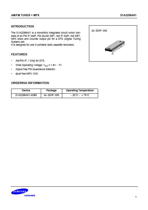
The S1A2298A01 is a monolithic integrated circuit which consists of an FM IF AMP, FM QUAD DET, AM IF AMP, AM DET, MPX block and Counter output pin for a DTS (Digital Tuning System) set. It is designed for use in portable radio cassette recorders. 24−SDIP−300
1 AMRF INPUT
2 IF SW
3
4
5
6
7
8
9
10
11 ST LED
12 GND
AM AMOSC VCC AGC LOWCUT OUTPUT
IF IF TU REQ COUNT LED
2
元器件交易网
AM/FM TUNER + MPX
S1A2298A01
PIN FUNCTION
AM MIX 23
NUC100中文手册

5.4.1 概述.................................................................................................................................46
3.3.2 NuMicro™ NUC100 Low Density引脚定义 ......................................................................24
4
框图 ........................................................................................................................................... 30
5.2 系统管理器 .................................................................................................................... 34
5.2.1 概述.................................................................................................................................34 5.2.2 系统复位..........................................................................................................................34 5.2.3 系统电源分配 ..................................................................................................................35 5.2.4 系统内存映射 ..................................................................................................................37 5.2.5 系统定时器(SysTick) .......................................................................................................39 5.2.6 嵌套向量中断控制器(NVIC).............................................................................................40
PD100MC0MP;PD100MC0MP1;中文规格书,Datasheet资料
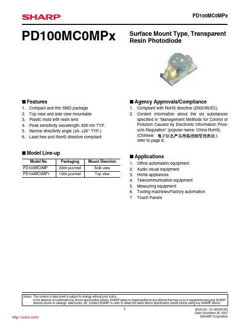
2. Content information about the six substances
specified in “Management Methods for Control of
Pollution Caused by Electronic Information Prod-
ucts Regulation” (popular name: China RoHS)
-40°
60
-50°
40
-60° 0°
-70°
-80° -90°
+90°
Anode Cathode -90°
20
0 Angle θ
+40°
+50° +60° +70° +80° +90°
■ Design Considerations
Design Guidelines
1. This product is not designed to be electromagnetic- and ionized-particle-radiation resistant.
θห้องสมุดไป่ตู้
*1 Ee: Irradiance by CIE standard light source A (tungsten lamp)
Fig. 1 Power Dissipation vs. Ambient Temperature
80 75 70
60
50
40
30
20 15 10
0
-30
0
25
50
75 85 100
(Chinese:
);
refer to page 6.
MA5600T V800R013C00SPC100 版本说明书 01
MA5600TV800R013C00SPC100 版本说明书文档版本01发布日期2013-07-25版权所有© 华为技术有限公司2013。
保留一切权利。
非经本公司书面许可,任何单位和个人不得擅自摘抄、复制本文档内容的部分或全部,并不得以任何形式传播。
商标声明和其他华为商标均为华为技术有限公司的商标。
本文档提及的其他所有商标或注册商标,由各自的所有人拥有。
注意您购买的产品、服务或特性等应受华为公司商业合同和条款的约束,本文档中描述的全部或部分产品、服务或特性可能不在您的购买或使用范围之内。
除非合同另有约定,华为公司对本文档内容不做任何明示或默示的声明或保证。
由于产品版本升级或其他原因,本文档内容会不定期进行更新。
除非另有约定,本文档仅作为使用指导,本文档中的所有陈述、信息和建议不构成任何明示或暗示的担保。
华为技术有限公司地址:深圳市龙岗区坂田华为总部办公楼邮编:518129网址:客户服务邮箱:support@客户服务电话:4008302118版本说明书目录目录1 版本配套说明 (1)1.1 产品版本信息 (1)1.2 支持的硬件及其版本配套说明 (1)1.3 硬件可替换关系 (7)1.4 相关产品版本配套说明 (7)2 版本更新说明 (9)2.1 V800R013C00 SPC100 (9)2.1.1 特性更新说明 (9)2.1.2 硬件更新说明 (16)2.1.3 用户接口更新说明 (19)3 已解决问题 (20)4 遗留问题 (23)5 升级影响 (27)6 版本配套文档 (28)6.1 V800R013C00版本配套文档 (28)6.2 版本配套文档更新说明 (28)6.3 获取文档的方法 (28)6.3.1 Support网站 (28)6.3.2 光盘和纸件 (29)A 缩略语 (30)1 版本配套说明1.1 产品版本信息产品版本中,“V”代表“Version”,“R”代表“Release”,“C”代表“Customization”。
M1A3P250-2VQ100IVQ100中文资料(Microsemi)中文数据手册「EasyDatasheet - 矽搜」

版本
器件手册章节可以有不同版本号. Actel目标是为客户提供及时事项最新信息.其结果是,该 表数据之前公布 已被充分表征.数据表被指定为"产品简介","高级",并 "生产".这些类别定义如下:
产品简介
产品简介是一个数据表摘要版本(高级或生产),包含 一般产品信息.本文给出具体设备和家庭概况 信息.
I / O说明和使用方法
I/在IGLOO和ProASIC3器件O结构. . . . . . . . . . . . . . . . . . . . . . . . . . . . . . . . . . . . . . . . . . . .7-1 I / O软件控制在低功耗闪存设备. . . . . . . . . . . . . . . . . . . . . . . . . . . . . . . . . . . . . . . . .8-1 DDR为Actel低功耗闪存设备. . . . . . . . . . . . . . . . . . . . . . . . . . . . . . . . . . . . . . . . . . . . . . . .9-1
封装和引脚说明 引脚说明. . . . . . . . . . . . . . . . . . . . . . . . . . . . . . . . . . . . . . . . . . . . . . . . . . . . . . . . . . . . . . . . . . .10-1 包装. . . . . . . . . . . . . . . . . . . . . . . . . . . . . . . . . . . . . . . . . . . . . . . . . . . . . . . . . . . . . . . . . . . . . . .11-1
龙芯 1B 处理器用户手册说明书

龙芯1B处理器用户手册2016年5月龙芯中科技术有限公司版权声明本文档版权归龙芯中科技术有限公司所有,并保留一切权利。
未经书面许可,任何公司和个人不得将此文档中的任何部分公开、转载或以其他方式散发给第三方。
否则,必将追究其法律责任。
免责声明本文档仅提供阶段性信息,所含内容可根据产品的实际情况随时更新,恕不另行通知。
如因文档使用不当造成的直接或间接损失,本公司不承担任何责任。
龙芯中科技术有限公司Loongson Technology Corporation Limited地址:北京市海淀区中关村环保科技示范园龙芯产业园2号楼Building No.2, Loongson Industrial Park, Zhongguancun Environmental Protection Park,电话(Tel):************传真(Fax):************阅读指南《龙芯1B处理器用户手册》主要介绍龙芯1B架构与寄存器描述。
修订历史文档更新记录文档编号:文档名:龙芯1B处理器用户手册版本号V2.3创建人:研发中心创建日期2016-5-4更新历史序号.更新日期更新人版本号更新内容12010-6-7 研发中心V1.0 1B处理器初稿完成22010-11-13 研发中心V1.1 增加了芯片引脚排布,DDR控制器信息等32010-11-15 研发中心V1.2 修改并进行标准排版42010-11-15 研发中心V1.3 修正了第五章DDR的部分错误52011-05-08 研发中心V1.4 修订了调试发现的错误62011-05-17 研发中心V1.5 修订了多个小问题72011-11-15 研发中心V1.6GMAC0/1的RGMII和MII模式需要配置才能使用GPIO配置和复用中修改bugSPI部分,分频时钟明确是DDR2_clk/2DDR2部分,配置16/32位可配置时钟分频部分有改动添加了LCD PAD在不同显示模式下的对应关系GPIO寄存器描述修改82012-4-11 研发中心V1.7 NAND部分寄存器说明修改XTALI/O 与外部有源晶振、无源晶体连接方法92012-4-20 研发中心V1.8 PAD封装位置和封装延迟GPIO复位值和方向GMAC0/1在MII模式下信号处理Wdog地址修改USB启动需要复位10 2012-05-26 研发中心V1.9 针对修改意见,做了GPIO/ LCD/ DMA/ SPI/ UART/I2C/ NAND /CLOCK的修改11 2014-07-30 研发中心V2.0 增加质量等级和封装顶视图12 2015-3-11 研发中心V2.1 增加电特性,CAN的速率计算13 2015-4-1 研发中心V2.2 补充质量等级描述14 2016-5-4 研发中心V2.3 24.1节增加RTC功耗说明,增加焊接要求手册信息反馈:*******************目录 (1)1概述 (1)1.1体系结构框图 (1)1.2芯片主要功能 (2)1.2.1GS232 CPU (2)1.2.2DDR2 (3)1.2.3LCD Controller (3)1.2.4USB2.0 (3)1.2.5AC97 (3)1.2.6GMAC (4)1.2.7SPI (4)1.2.8UART (4)1.2.9I2C (4)1.2.10PWM (4)1.2.11CAN (5)1.2.12RTC (5)1.2.13GPIO (5)1.2.14NAND (5)1.2.15INT controller (5)1.2.16Watchdog (5)1.2.17功耗 (5)1.2.18其它 (7)1.3质量等级 (7)2芯片引脚定义 (9)2.11B引脚分布图 (9)2.2封装顶视图 (16)2.3系统相关引脚定义(6) (17)2.4LCD引脚定义(20) (17)2.5PLL引脚定义(4) (17)2.6VR引脚定义(6) (18)2.7DDR2引脚定义(71) (18)2.8USB引脚定义(10) (19)2.9EJTAG引脚定义(6) (20)2.10GMAC0引脚定义(15) (20)2.11GMAC1引脚定义(4) (20)2.12AC97引脚定义(5) (21)2.13SPI引脚定义(7) (21)2.14UART引脚定义(20) (21)2.15I2C引脚定义(2) (22)2.16CAN引脚定义(4) (22)2.17NAND引脚定义(14) (22)2.18PWM引脚定义(4) (22)2.19电源/地引脚(58) (23)3地址空间分配 (24)3.1一级AXI交叉开关上模块的地址空间 (24)3.2AXI MUX下各模块的地址空间 (24)3.3APB各模块的地址空间分配 (24)4CPU (26)4.1MIPS32指令系统结构 (26)4.1.1CPU寄存器 (27)4.1.2CPU指令集 (27)4.1.3CP0指令集 (31)4.1.4存储空间 (32)4.1.5例外处理 (33)4.1.6CP0寄存器 (35)4.2CP0指令 (53)4.3EJTAG设计 (53)4.3.1EJTAG介绍 (53)4.3.2调试控制寄存器(Debug Control Register) (54)4.3.3硬件断点 (56)4.3.4EJTAG相关的处理器核扩展 (61)4.3.5TAP接口 (64)5DDR2 (72)5.1DDR2SDRAM控制器特性 (72)5.2DDR2SDRAM读协议 (72)5.3DDR2SDRAM写协议 (73)5.4DDR2SDRAM参数设置顺序 (73)5.5DDR2SDRAM采样模式配置 (74)5.6DDR2SDRAM PAD驱动配置 (74)5.7DDR216位工作模式配置 (74)6LCD (75)6.1特性 (75)6.1.1数据格式 (75)6.2寄存器 (75)7GMAC0 (81)7.1配置成MAC的连接和复用方式 (81)7.2DMA寄存器描述 (81)7.3GMAC控制器寄存器描述 (90)7.4DMA描述符 (101)7.4.1DMA描述符的基本格式 (101)7.4.2DMA接收描述符 (102)7.4.3RDES0 (103)7.4.4RDES (104)7.4.5RDES2 (105)7.4.6RDES3 (105)7.4.7DMA发送描述符 (106)7.4.8TDES0 (106)7.4.9TDES1 (107)7.4.10TDES2 (109)7.4.11TDES3 (109)7.5软件编程向导(S OFTWARE P ROGRAMMING G UIDE): (110)8GMAC1 (112)8.1配置成MAC的连接和复用方式 (112)8.2GMAC1外部信号复用和配置 (112)8.3寄存器描述 (113)9USB HOST (114)9.1总体概述 (114)9.2USB主机控制器寄存器 (115)9.2.1EHCI相关寄存器 (115)9.2.2Capability寄存器 (115)9.2.3Operational寄存器 (116)9.2.4EHCI 实现相关寄存器 (116)INSNREG00寄存器(disable) (117)INSNREG01寄存器 (117)INSNREG02寄存器 (117)INSNREG03寄存器 (117)INSNRE04寄存器(仅用于调试,软件不必更改此寄存器) (117)INSNRE05寄存器 (118)INSNREG06寄存器 (118)INSNREG07寄存器 (118)INSNREG08寄存器 (118)9.3OHCI相关寄存器 (119)9.3.1Operational寄存器 (119)9.3.2OHCI 实现相关寄存器 (119)INSNREG06寄存器 (120)INSNREG07寄存器 (120)9.4USB主机控制器时序 (120)9.4.1数据接收时序 (120)9.4.2数据传输时序 (121)10SPI0 (123)10.1SPI控制器结构 (123)10.2SPI控制器寄存器 (124)10.2.1控制寄存器(SPCR) (124)10.2.2状态寄存器(SPSR) (124)10.2.3数据寄存器(TxFIFO/RxFIFO) (125)10.2.4外部寄存器(SPER) (125)10.2.5参数控制寄存器(SFC_PARAM) (125)10.2.6片选控制寄存器(SFC_SOFTCS) (126)10.2.7时序控制寄存器(SFC_TIMING) (126)10.3接口时序 (126)SPI主控制器外部接口时序图 (126)SPI Flash访问时序图 (127)10.4SPI F LASH控制器使用指南 (128)SPI主控制器的读写操作 (128)硬件SPI Flash读 (128)混合访问SPI Flash和SPI主控制器 (129)11SPI1 (130)11.1SPI主控制器结构 (130)12Conf and Interrupt (131)12.1配置和中断控制器总体描述 (131)12.2中断控制器寄存器描述 (132)13DMA (134)13.1DMA控制器结构描述 (134)13.2DMA控制器与APB设备的交互 (134)13.3DMA控制器 (134)13.3.1ORDER_ADDR_IN (134)13.3.2DMA_ORDER_ADDR (135)13.3.3DMA_SADDR (135)13.3.4DMA_DADDR (136)13.3.5DMA_LENGTH (136)13.3.6DMA_STEP_LENGTH (136)13.3.7DMA_STEP_TIMES (137)13.3.8DMA_CMD (137)14UART (139)14.1UART控制器结构 (139)14.2UART控制器寄存器 (140)14.2.1数据寄存器(DAT) (141)14.2.2中断使能寄存器(IER) (141)14.2.3中断标识寄存器(IIR) (141)14.2.4FIFO控制寄存器(FCR) (142)14.2.5线路控制寄存器(LCR) (142)14.2.6MODEM控制寄存器(MCR) (143)14.2.7线路状态寄存器(LSR) (143)14.2.8MODEM状态寄存器(MSR) (144)14.2.9分频锁存器 (144)15CAN (146)15.1概述 (146)15.2CAN控制器结构 (146)15.3标准模式 (147)15.3.1标准模式地址表 (147)15.3.2控制寄存器(CR) (148)15.3.3命令寄存器(CMR) (149)15.3.4状态寄存器(SR) (149)15.3.5中断寄存器(IR) (149)15.3.6验收代码寄存器(ACR) (150)15.3.7验收屏蔽寄存器(AMR) (150)15.3.8发送缓冲区列表 (150)15.3.9接收缓冲区列表 (150)15.4扩展模式 (151)15.4.1扩展模式地址表 (151)15.4.2模式寄存器(MOD) (151)15.4.3命令寄存器(CMR) (152)15.4.4状态寄存器(SR) (152)15.4.5中断寄存器(IR) (152)15.4.6中断使能寄存器(IER) (153)15.4.7仲裁丢失捕捉寄存器(IER) (153)15.4.8错误警报限制寄存器(EMLR) (154)15.4.9RX错误计数寄存器(RXERR) (155)15.4.10TX错误计数寄存器(TXERR) (155)15.4.11验收滤波器 (155)15.4.12RX信息计数寄存器(RMCR) (155)15.5公共寄存器 (155)15.5.1总线定时寄存器0(BTR0) (155)15.5.2总线定时寄存器1(BTR1) (156)15.5.3输出控制寄存器(OCR) (156)16AC97 (157)16.1AC97结构描述 (157)16.2AC97控制器寄存器 (157)16.2.1CSR寄存器 (158)16.2.2OCC寄存器 (158)16.2.3ICC寄存器 (158)16.2.4(输入输出)通道寄存器配置 (159)16.2.5Codec寄存器访问命令 (159)16.2.6中断状态寄存器/中断掩膜寄存器 (160)16.2.7中断状态/清除寄存器 (160)16.2.8OC中断清除寄存器 (160)16.2.9IC中断清除寄存器 (160)16.2.10CODEC WRITE 中断清除寄存器 (161)16.2.11CODEC READ 中断清除寄存器 (161)17I2C (162)17.1概述 (162)17.2I2C控制器结构 (162)17.3I2C控制器寄存器说明 (163)17.3.1分频锁存器低字节寄存器(PRERlo) (163)17.3.2分频锁存器高字节寄存器(PRERhi) (163)17.3.3控制寄存器(CTR) (164)17.3.4发送数据寄存器(TXR) (164)17.3.5接受数据寄存器(RXR) (164)17.3.6命令控制寄存器(CR) (164)17.3.7状态寄存器(SR) (165)18PWM (166)18.1概述 (166)18.2PWM寄存器说明 (166)19RTC (168)19.1概述 (168)19.2寄存器描述 (168)19.2.1寄存器地址列表 (168)19.2.2SYS_TOYWRITE0 (169)19.2.3SYS_TOYWRITE1 (169)19.2.4SYS_TOYMATCH0/1/2 (169)19.2.5SYS_RTCCTRL (170)19.2.6SYS_RTCMATCH0/1/2 (171)20NAND (172)20.1NAND控制器结构描述 (172)20.2NAND控制器寄存器配置描述 (172)20.2.1NAND_CMD(地址:BFE7_8000) (172)20.2.2ADDR_L(地址:BFE7_8004) (173)20.2.3ADDR_H(地址:BFE7_8008) (173)20.2.4NAND_TIMING(地址:BFE7_800C) (173)20.2.5ID_L(地址:BFE7_8010) (173)20.2.6STATUS & ID_H(地址:BFE7_8014) (173)20.2.7NAND_PARAMETER(地址:BFE7_8018) (173)20.2.8NAND_OP_NUM(地址:BFE7_801C) (173)20.2.9CS_RDY_MAP(地址:BFE7_8020) (174)20.2.10DMA_ADDRESS(地址:BFE7_8040) (174)20.3NAND ADDR说明 (174)21WATCHDOG (177)21.1概述 (177)21.2WATCH DOG寄存器描述 (177)21.2.1WDT_EN地址:(0XBFE5_C060) (177)21.2.2WDT_SET(地址:0XBFE5_C068) (178)21.2.3WDT_timer(地址:0XBFE5_C064) (178)22Clock Management (179)22.1C LOCK模块结构描述 (179)22.2C LOCK配置描述 (179)22.3系统其它C LOCK描述 (180)23GPIO and MUX (181)23.1GPIO结构描述 (181)23.2GPIO寄存器描述 (184)23.3MUX寄存器描述 (185)24AC/DC (187)24.1电源域 (187)24.2系统复位 (187)24.3推荐的工作条件 (187)24.4绝对最大额定值 (188)25热特性 (189)25.1焊接温度 (189)图目录图1-1 1B芯片结构图 (2)图 4-1 TLB表项内容 (33)图 4-2 Index 寄存器 (36)图 4-3 Random寄存器 (37)图 4-4 EntryLo0和EntryLo1寄存器 (37)图 4-5 Context寄存器 (38)图 4-6 PageMask寄存器 (38)图 4-7 Wired寄存器界限 (39)图 4-8 Wired寄存器 (40)图 4-9 HWREna寄存器 (40)图 4-10 BadVAddr寄存器 (40)图 4-11 Count寄存器和Compare寄存器 (41)图 4-12 EntryHi寄存器 (41)图 4-13 Status寄存器 (42)图 4-14 IntCtl寄存器 (43)图 4-15SRSCtl寄存器 (44)图 4-16 SRSMap寄存器 (44)图 4-17 Cause寄存器 (45)图 4-18 EPC寄存器 (46)图4-19 Processor Revision Identifier 寄存器 (46)图 4-20 Config寄存器 (47)图 4-21 Config寄存器 (48)图 4-22 Config寄存器 (48)图 4-23 Config寄存器 (49)图 4-24 Config寄存器 (49)图 4-25 WatchLo寄存器 (50)图 4-26 WatchHi寄存器 (50)图 4-27 控制寄存器性能计数寄存器 (51)图 4-28 性能计数器寄存器 (51)图 4-29 TagLo 寄存器(P-Cache) (52)图 4-30 ErrorEPC寄存器 (53)图 4-31 EJTAG调试连接示意图 (54)图 4-32 DCR寄存器格式 (55)图 4-33 硬件指令、数据断点概况 (56)图 4-34 IBS寄存器格式 (57)图 4-35 IBAn寄存器格式 (58)图 4-36 IBMn寄存器格式 (58)图 4-37 IBCn寄存器格式 (58)图 4-38 DBS寄存器格式 (59)图 4-39 DBAn寄存器格式 (60)图 4-40 DBMn寄存器格式 (60)图 4-41 DBCn寄存器格式 (60)图4-42 TAP主要部分 (64)图4-43 ALL指令示意图 (65)图4-44 Fastdata 指令示意图 (65)图 4-45 IDCODE寄存器格式 (66)图 4-46 IMPCADE寄存器示意图 (67)图 4-47 数据寄存器格式 (68)图 4-48 地址寄存器格式 (69)图 4-49 ECR格式 (69)图9-1 USB主机控制器模块图 (114)图9-2 USB主机控制器细节模块图(带EHCI控制器细节) (115)图9-3 接收时序图(16 bit UTMI接口,偶数个数据) (121)图9-4 接收时序图(16 bit UTMI接口,奇数个数据) (121)图9-5 传输时序图(16 bit UTMI接口,偶数个数据) (122)图9-6 传输时序图(16bit UTMI接口,奇数个数据) (122)图10-1 SPI 主控制器结构 (124)图10-2SPI主控制器时序图 (127)图16-1 AC97应用系统 (157)图21-1 看门狗的结构图 (177)图25.1 焊接回流曲线 (189)表目录表 4-1 CPU指令集:访存指令 (27)表 4-2 CPU 指令集:算术指令 (ALU 立即数) (28)表 4-3 CPU 指令集:算术指令 (2操作数) (28)表 4-4 CPU指令集:算术指令(3操作数, R-型) (28)表 4-5 CPU指令集:乘法和除法指令 (29)表 4-6 CPU指令集:跳转和分支指令 (29)表 4-7 CPU指令集:移位指令 (30)表 4-8 CPU指令集:特殊指令 (30)表 4-9 CPU指令集:异常指令 (30)表 4-10 CPU指令集:CP0指令 (31)表 4-11 GS232的CP0指令 (31)表 4-12 GS232IP地址空间的分配 (32)表 4-13 例外编码及寄存器修改 (33)表 4-14 例外入口地址 (34)表 4-15 GS232IP实现的CP0 寄存器 (35)表 4-16 Index寄存器各域描述 (36)表 4-17 Random寄存器各域 (37)表 4-18 EntryLo寄存器域 (37)表 4-19 Context寄存器域 (38)表 4-20 不同页大小的掩码(Mask)值 (39)表 4-21 Wired寄存器域 (40)表 4-22 HWREna寄存器域 (40)表 4-23 EntryHi寄存器域 (41)表 4-24 Status 寄存器域 (42)表 4-25 IntCtl寄存器域 (43)表 4-26 SRSCtl寄存器域 (44)表 4-27Cause寄存器域 (45)表 4-28 Cause寄存器的ExcCode域 (45)表 4-29 PRId 寄存器域 (46)表 4-30 Config 寄存器域 (47)表 4-31 Config 寄存器域 (48)表 4-32 Config 寄存器域 (48)表 4-33 Config 寄存器域 (49)表 4-34 Config 寄存器域 (49)表 4-35 WatchLo寄存器域 (50)表 4-36 WatchHi寄存器域 (50)表 4-37控制域格式 (51)表 4-38 计数使能位定义 (51)表 4-39 计数器0/1事件 (51)表 4-40 Cache Tag寄存器域 (52)表 4-41 CP0指令 (53)表 4-42 DCR寄存器域 (55)表 4-43 硬件断点寄存器 (56)表 4-44 IBS域描述 (57)表 4-45 IBCn域描述 (58)表 4-46 DBS域描述 (59)表 4-47 DBCn域描述 (60)表 4-48 调试例外优先级表 (61)表 4-49 例外屏蔽表 (62)表 4-50 Dseg划分 (63)表 4-51 Dmseg的访问情况 (63)表 4-52 Drseg的访问情况 (63)表 4-53 调试例外中断入口地址 (64)表 4-54 EJTAG指令 (64)表 4-55 TAP数据寄存器 (66)表 4-56 IDCODE寄存器说明 (66)表 4-57 IMPCODE寄存器说明 (67)表 4-58 Psz位的含义 (68)表 4-59 ECR域描述 (69)表 4-60 Sample寄存器说明 (70)表18-18-1 四路控制器描述 (166)表18-18-2 控制寄存器描述 (166)表18-18-3 主计数器设置 (166)表18-18-4 高脉冲计数器设置 (166)表18-18-5 低脉冲计数器设置 (167)表18-18-6 控制寄存器设置 (167)表24-1 1B电源域 (187)表24-2 1B上电配置引脚汇总 (187)表24-3推荐的工作条件 (187)表24-4绝对最大额定值 (188)表25-1 回流焊接温度要求 (189)1 概述龙芯1B芯片是基于GS232处理器核的片上系统,具有高性价比,可广泛应用于工业控制、家庭网关、信息家电、医疗器械和安全应用等领域。
CJT011000DB中文资料

188 Technology Drive Unit H, Irvine, CA 92618 TEL: 949-453-9888 FAX: 949-453-8889 3TAPE SCHEMATICTAPE DIMENSIONS (mm)0201 0402 0603 0805A 0.41±0.1 0.65±0.1 1.1±0.2 1.65±0.2B 0.71±0.1 1.15±0.1 1.9±0.2 2.4±0.2W 8.0±0.2 8.0±0.2 8.0±0.2 8.0±0.2E 1.75±0.10 1.75±0.10 1.75±0.1 1.75±0.1F 3.5±0.05 3.5±0.05 3.5±0.05 3.5±0.05P1 2.0±0.05 2.0±0.05 4.0±0.1 4.0±0.1T 0.5max0.55±0.1 0.70±0.1 0.90±0.1T p 0.4+0.05 0.40±0.05 0.60±0.1 0.75±0.11206 1210 2010 2512A 2.0±0.15 2.9±0.1 2.9±0.1 3.4±0.1B 3.6±0.15 3.5±0.1 5.3±0.1 6.6±0.1W 8.0±0.2 8.0±0.2 12.0±0.2 12.0±0.2E 1.75±0.1 1.75±0.1 1.75±0.1 1.75±0.1F 3.5±0.05 3.5±0.05 5.5±0.05 5.5±0.05P1 4.0±0.1 4.0±0.1 4.0±0.1 4.0±0.1T 0.90±0.1 0.90±0.1 1.0±0.1 1.0±0.1T p0.75±0.1 0.75±0.1 0.25±0.1 0.25±0.1TAPE TYPE0201 0402 0603 0805 1206 1210 2010 2512Paper Tape Plastic TapeTAPE MATERIALSA heat press sticks the transparent or half-transparent plasticcovered tape.PACKAGE QUANTITYType0201 0402 0603 0805B 25,00010,000 M 10,000 10,000 5,000 5,000 V 40,000 40,000 20,000 20,000Type1206 1210 2010 2512B 5,000M 5,000 4,000 4,000 4,000 V 20,000 20,000 20,000 20,000The content of this specification may change without notification REEL DRAWINGS7” Reel (M) 13” Reel (V) PACKAGE DIMENSIONS (mm)7” Reel (M) 13” Reel (V) M 180 ± 3.0 330±2.5 H 1.20 2.3± 0.5 C 13.0 ± 0.2 13.0 ± 0.2 G 9.0 ± 0.3 9.5 ± 0.5 E 60 ± 1.0 80.0 ±1.0F 11.4 ± 1.0 14.4BULK CASE SCHEMATICBULK CASE DIMENSIONS (mm)A B C D E110. 0± 0.736.0 ± 0.2 12.0 ± 0.1 31.5 ±0.2 36.0±0.2F G H I J K6.8 ±0.1 8.8 ±0.1 12.0 ± 0.1 1.5 ± 0.1 2.0± 0.1 4.7± 0.1LABEL DESCRIPTIONOne side surface of a reel is marked with a label with thefollowing items of information.1. ChipResistor2. PartNumber3. Tolerance4. Quantity5. Lot number for production month/year/suffix L*6. Manufacturer’s name or symbol* The suffix “L” indicates that this item is lead free. As of September2004, all new production items of the series CR and CJ are nolonger containing tin/lead (SnPb) terminals; they are lead free and incompliance with Lead Free/RoHS.American Accurate Components, Inc.188 Technology Drive Unit H, Irvine, CA 92618 TEL: 949-453-9888 FAX: 949-453-8889 4CR-KITS Series, Thick Film Chip Resistor Engineering KitsThis engineering and design kit is a great sales tool, allowing for application testing before ordering minimum quantities. AAC offers a wide assortment of popular chip resistors sizes and tolerances, in addition to a large quantity of each value. The kits are convenient with easy-to-use packaging.PACKAGE CONSTRUCTION E-24 KIT VALUES3 Ring Binder Case HolderPlastic pages with slip holders for each valueEach value is individually identified in a slip holder Resistors are packaged on paper tape strips 2.22.73.94.76.88.21018222733394768751001201501802202703303904705606808501.0K1.2K1.5K1.8K2.2K2.7K3.3K3.9K4.7K5.6K6.8K8.2K10K12K15K18K22K27K33K39K47K56K82K100K120K150K220K270K390K470K560K1.0M2.2ME-96 KIT VALUES10.011.312.113.315.016.5 18.2 20.0 22.1 24.326.128.733.235.739.242.246.451.156.261.968.175.082.590.91001071181331501621742002152372612873013323483834224755115496046817508259091.00K1.10K1.21K1.33K1.50K1.62K1.82K2.00K2.21K2.37K2.67K3.01K3.32K3.92K4.22K4.75K5.11K5.62K6.19K6.81K7.50K8.25K9.09K10.0K11.0K12.1K13.0K15.0K16.2K18.2K20.0K22.1K23.7K27.4K30.1K33.2K39.2K41.2K47.5K49.9K56.2K60.4K68.1K75.0K82.5K90.9K100K110K121K130K150K162K178K200K221K237K255K274K301K332K365K392K422K464K511K536K562K619K649K681K732K750K825K866K909K953K1.0MEngineering Kits J TypeFEATURESEIA Standard E-24 ValuesFull range from 1 Ω ~ 1M ΩResistance Tolerance of +5%3,000 Pieces: 50 pieces of 60 different values ISO 9002 Quality Certified productsPart Number for +5% Sample Kit Part Number DescriptionCR05-J-KITS 0402, 1/16w, 5%, E-24 values (1Ω through 2.2M Ω)CR16-J-KITS 0603, 1/16w, 5%, E-24 values (1Ω through 2.2M Ω)CR10-J-KITS 0805, 1/10w, 5%, E-24 values (1Ω through 2.2M Ω)CR18-J-KITS 1206, 1/8w, 5%, E-24 values(1Ω through 2.2M Ω)Engineering Kits F TypeFEATURESEIA Standard E-24 ValuesFull range from 10 Ω ~ 1M ΩResistance Tolerance of +1%3,150 Pieces: 25 pieces of 126 different valuesISO 9002 Quality Certified productsPart Number for +1% Sample KitPart Number DescriptionCR05-F-KITS0402, 1/16w, 1%, E-96 values(10 Ω through 1M Ω)CR16-F-KITS0603, 1/16w, 1%, E-96 values(10 Ω through 1M Ω)CR10-F-KITS0805, 1/10w, 1%, E-96 values(10 Ω through 1M Ω)CR18-F-KITS1206, 1/8w, 1%, E-96 values(10 Ω through 1M Ω)American Accurate Components, Inc.Copyright © Each Manufacturing Company.All Datasheets cannot be modified without permission.This datasheet has been download from :100% Free DataSheet Search Site.Free Download.No Register.Fast Search System.。
SPC-0101(中文说明书)-A0
d) 避免不必要的走动; e) 拿产品部件(尤其是板卡)时仅拿住边缘; f) 将产品部件置于一个接地的无静电的操作平台上。如果可能
的话,使用一块导电泡沫垫(非部件的包装材料); g) 不要让部件在操作平台上滑动。 9. 用十字螺丝刀进行操作,最好是强力螺丝刀(带磁性,避免螺丝 遗留在机箱内)。要注意的是,一定不要将工具或零件遗漏在机 箱内; 10. 保证系统良好的散热与通风。
ห้องสมุดไป่ตู้
IDE接口 ...................................................................................................13 并口 .........................................................................................................14 串口 .........................................................................................................14 USB接口..................................................................................................15 显示接口 .................................................................................................15 网络接口 .................................................................................................16 键盘与鼠标接口......................................................................................17 风扇接口 .................................................................................................18 PC104 接口..............................................................................................19 PCI-104PLUS接口 ..................................................................................20 CompactFlash接口 ..................................................................................21 电源输入及失电报警控制接口..............................................................22 机器工作状态指示接口..........................................................................23 第四章 BIOS功能简介...........................................................................26 附录 .........................................................................................................27 Watchdog编程指引 .................................................................................27 I/O口地址映射表 ....................................................................................31 IRQ中断分配表.......................................................................................32 第五章 驱动程序的安装........................................................................33
神盾ICR-100MB身份证阅读器详解
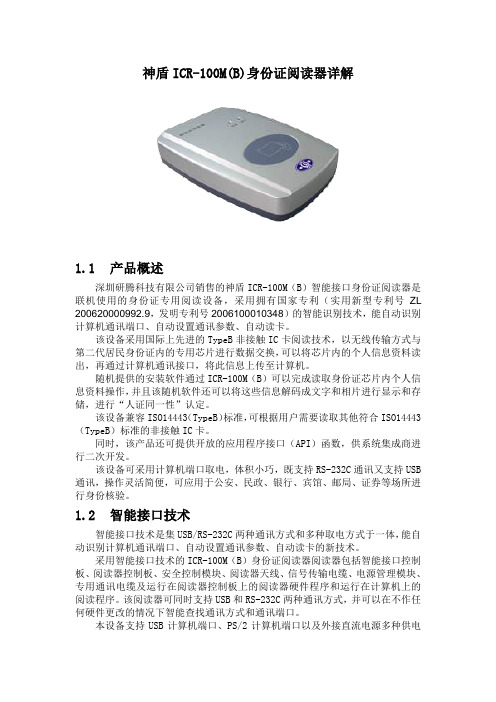
神盾ICR-100M(B)身份证阅读器详解1.1产品概述深圳研腾科技有限公司销售的神盾ICR-100M(B)智能接口身份证阅读器是联机使用的身份证专用阅读设备,采用拥有国家专利(实用新型专利号ZL 200620000992.9,发明专利号2006100010348)的智能识别技术,能自动识别计算机通讯端口、自动设置通讯参数、自动读卡。
该设备采用国际上先进的TypeB非接触IC卡阅读技术,以无线传输方式与第二代居民身份证内的专用芯片进行数据交换,可以将芯片内的个人信息资料读出,再通过计算机通讯接口,将此信息上传至计算机。
随机提供的安装软件通过ICR-100M(B)可以完成读取身份证芯片内个人信息资料操作,并且该随机软件还可以将这些信息解码成文字和相片进行显示和存储,进行“人证同一性”认定。
该设备兼容ISO14443(TypeB)标准,可根据用户需要读取其他符合ISO14443(TypeB)标准的非接触IC卡。
同时,该产品还可提供开放的应用程序接口(API)函数,供系统集成商进行二次开发。
该设备可采用计算机端口取电,体积小巧,既支持RS-232C通讯又支持USB 通讯,操作灵活简便,可应用于公安、民政、银行、宾馆、邮局、证券等场所进行身份核验。
1.2智能接口技术智能接口技术是集USB/RS-232C两种通讯方式和多种取电方式于一体,能自动识别计算机通讯端口、自动设置通讯参数、自动读卡的新技术。
采用智能接口技术的ICR-100M(B)身份证阅读器阅读器包括智能接口控制板、阅读器控制板、安全控制模块、阅读器天线、信号传输电缆、电源管理模块、专用通讯电缆及运行在阅读器控制板上的阅读器硬件程序和运行在计算机上的阅读程序。
该阅读器可同时支持USB和RS-232C两种通讯方式,并可以在不作任何硬件更改的情况下智能查找通讯方式和通讯端口。
本设备支持USB计算机端口、PS/2计算机端口以及外接直流电源多种供电方式,大大增强了设备使用的灵活性,方便用户根据自身情况做出选择,满足了用户的多样化需求。
ES1001-9PDDB1中文资料(Power-One)中文数据手册「EasyDatasheet - 矽搜」
Page
电磁兼容性(EMC).................................... 15 抗扰度环境条件.................................. 17 机械数据................................................ .................... 18 安全和安装说明........................................ 19 选项说明............................................... ............. 23 配件................................................. ........................... 32 EC-一致性声明............................................. ... 33
C S 2 5 40 -9 E R
系列................................................. ...............................小号
输出数量............................................... ......... 1,2
Eff. 输入电压
Eff. 选项
V算I一个- VI最大
[%] 20至100伏直流
[%]
77
FS1001-7R
83
FS1301-7R
77
-9
83 E , -9E
84
FS1501-7R
84
V
SEC1001中文资料

λp
∆λ
Outline drawing
(nm) typ 700 630 660 560 555 610 587 560 630 560 660 630 560 660 570 560 630 560 660 570 660 100 35 30 20 20 35 33 20 35 20 30 35 20 30 40 20 35 20 30 40 30
50
· θ 1/2 = 70° ·
50
90° 100%
SEC1003
0° 30° 30° 60°
60° 30°
SEC2004
0° 30° 60°
60°
90° 100%
50
· θ 1/2 = 35° ·
50
90° 100%
90° 100%
50
· θ 1/2 = 30° ·
50
90° 100%
Absolute maximum ratings (Ta=25°C) Symbol Unit IF mA IFP mA VR V Top °C Tstg °C
+0
11.4 9.0
±1.0
±0.3
Cathode
3.5±0.05
8.0
2.0±0.2
ø13±0.2
1.9
4.0 2.0±0.05
4.0
ø60–0
+1
Bicolor SEC2002/SEC2004 series
1.75
30° ø10 ø22
0.2
±0.05
ø1.5+0.1 0
Cathode
3.5±0.05
3 Manual Soldering: Not more than 3 seconds at MAX 300°C, under soldering iron.
龙芯 1B 开发学习套件 用户手册说明书

1、电源和开关 ..............................................................................................................................7 2、ADC和DAC .................................................................................................................................7 3、串口和 485...............................................................................................................................8 4、Debug调试接口 .......................................................................................................................8 5、CAN接口....................................................................................................................................8 6、DC插座 ......................................................................................................................................9 7、LCD 接口................................................................................................................................10 第二章 LoongIDE集成开发环境 ...............................................................................................................11 第一节 系统安装 ................................................................................................................................11 1、运行环境 ................................................................................................................................11 2、LoongIDE安装.......................................................................................................................11 3、GNU 工具链............................................................................................................................12 4、注意事项 ................................................................................................................................13 第二节 串口控制台 ............................................................................................................................13 第三节 常见问题 ................................................................................................................................14 1、LxLink驱动安装 ...................................................................................................................14 2、引导程序PMON........................................................................................................................15 第四节 编程前准备 ............................................................................................................................16 1、设置默认工作区 ....................................................................................................................16 2、工具链配置 ............................................................................................................................16 3、主机IP地址 ............................................................................................................................17 第三章 设备驱动与编程参考.....................................................................................................................18 第一节 创建项目框架.........................................................................................................................18 1、项目向导 ................................................................................................................................18 2、项目目录与文件 ....................................................................................................................19 第二节 配置BSP..................................................................................................................................20 1、片上设备使用列表 ................................................................................................................20 2、SPI0 总线上的从设备...........................................................................................................21
WS1M8-100CC中文资料

White Electronic Designs WS1M8-XCXPRELIMINARY*2x512Kx8 DUALITHIC™ SRAMFEATURESAccess Times 70, 85, 100nsEvolutionary, Corner Power/Ground PinoutPackaging:• 32 pin, Hermetic Ceramic DIP (Package 300)Organized as two banks of 512Kx8Commercial, Industrial and Military TemperatureRanges5 Volt Power SupplyLow Power CMOSTTL Compatible Inputs and OutputsOutput Enable Internally tied to GND.*T his product is under development, is not qualifi ed or characterized and is subject tochange without notice.White Electronic Designs WS1M8-XCXPRELIMINARYABSOLUTE MAXIMUM RATINGS Parameter Symbol Min Max Unit Operating Temperature T A-55 +125°C Storage Temperature T STG-65+150°C Signal Voltage Relative to GND V G-0.5V CC+0.5V Junction Temperature T J150°C Supply Voltage V CC-0.57.0VRECOMMENDED OPERATING CONDITIONS Parameter Symbol Min Max Unit Supply Voltage V CC 4.5 5.5V Input High Voltage V IH 2.2V CC + 0.3V Input Low Voltage V IL-0.3+0.8V Opertating Temp. (MIL)T A-55+125°CTRUTH TABLECS#WE#Mode Data I/O PowerH X Standby High Z StandbyL H Read Data Out ActiveL L Write Data In ActiveCAPACITANCET A = +25°CParameter Symbol Conditions Max Unit Input capacitance C IN V IN = 0V, f = 1.0 MHz28pF Output capacitance C OUT V OUT = 0V, f = 1.0 MHz28pF This parameter is guaranteed by design but not tested.DC CHARACTERISTICSV CC = 5.0V, V SS = 0V, -55°C ≤ T A≤ +125°CParameter Sym Conditions Min Max Units Input Leakage Current I LI V CC = 5.5, V IN = GND to V CC10µA Output Leakage Current I LO1CS# = V IH, V OUT = GND to V CC10µA Operating Supply Current I CC1CS# = V IL, f = 5MHz, V CC = 5.555mA Standby Current I SB1CS# = V IH, f = 5MHz, V CC = 5.52mA Output Low Voltage V OL I OL = 2.1mA0.4V Output High Voltage V OH I OH = -1.0mA 2.4V NOTE: DC test conditions: V IH = V CC -0.3V, V IL = 0.3V1. OE# is internally tied to GND.DATA RETENTION CHARACTERISTICS-55°C ≤ T A≤ +125°CCharacteristic Sym Conditions Min Typ Max Units Data Retention Supply Voltage V DR CS# ≥ V CC -0.2V 2.0 5.5V Data Retention Current I CCDR1V CC = 3V150800*µA * Also available in Low Power version. Please call factory for informaion.White Electronic DesignsWS1M8-XCXPRELIMINARYAC CHARACTERISTICSV CC = 5.0V, GND = 0V, -55°C ≤ T A ≤ +125°CParameter Write Cycle Symbol -70-85-100UnitsMin MaxMin MaxMin MaxWrite Cycle Timet WC 7085100ns Chip Select to End of Write t CW 607580ns Address Valid to End of Write t AW 607580ns Data Valid to End of Write t DW 303040ns Write Pulse Width t WP 505060ns Address Setup Time t AS 000ns Address Hold Timet AH 555ns Output Active from End of Write t OW 1555ns Write Enable to Output in High Z t WHZ 1252535ns Data Hold Timet DHns 1. This parameter is guaranteed by design but not tested.AC CHARACTERISTICSV CC = 5.0V, GND = 0V, -55°C ≤ T A ≤ +125°CParameter Read CycleSymbol -70-85-100Units Min Max Min Max Min Max Read Cycle Time t RC 7085100ns Address Access Timet AA 7085100ns Output Hold from Address Change t OH 00ns Chip Select Access Timet ACS 7085100ns Chip Select to Output in Low Z t CLZ 1555ns Chip Disable to Output in High Zt CHZ 1252525ns1. This parameter is guaranteed by design but not tested.AC TEST CIRCUITWhite Electronic Designs WS1M8-XCXPRELIMINARY TIMING WAVEFORM – READ CYCLEWRITE CYCLE – WE# CONTROLLEDWhite Electronic Designs WS1M8-XCXPRELIMINARY PACKAGE 300: 32 PIN, CERAMIC DIP, SINGLE CAVITY SIDE BRAZEDALL LINEAR DIMENSIONS ARE MILLIMETERS AND PARENTHETICALLY IN INCHESORDERING INFORMATIONW S 1M8 - XXX C X XLEAD FINISH:Blank = Gold plated leadsA = Solder dip leadsGRADE:DEVICEM = Military Screened -55°C to +125°CI = Industrial -40°C to +85°CC = Commercial 0°C to +70°CPACKAGE:C = Ceramic 0.600" DIP (Package 300)ACCESS TIME (ns)ORGANIZATION, two banks of 512K x 8SRAMWHITE ELECTRONIC DESIGNS CORP.。
MB2S MB4S MB6S MB8S MB10S 芯片数据手册说明书

Features◆ Plastic package has Underwriters Laboratory FlammabilityClassification 94V-0◆ Glass passivated chip junctions ◆ High surge overload rating:35A peak ◆Saves space on printed circuit boards◆ High temperature soldering guaranteed:260℃/10 seconds ◆ Add suffix "E" for Halogen Free◆ Halogen-free according to IEC 61249-2-21 definitionMechanical Data◆Case:Molded plastic body over passivated junctions ◆ Terminals: plated leads solderable per MIL-STD-750,Method 2026◆ Mounting Position:Any ◆Weight:0.078 oz.,0.22gMaximum Ratings & Electrical Characteristics(T A =25℃ unless otherwise noted)ParameterSymbol MB2S MB4S MB6S MB8S MB10S Unit Maximum repetitive peak reverse voltage V RRM 2004006008001000V Maximum RMS voltage V RMS 140280420560700V Maximum DC blocking voltageV DC2004006008001000VMaximum Average forward output current (see Fig.1) on glass-epoxy P.C.B on aluminum substratePeak forward surge current 8.3 MS single HALF sine-wav superimposed on rated load (JEDEC Method)A350.5(1)0.8(2)A I F(AV)I FSM p p ()Rating for fusig (t<8.3ms)I 2t A 2sec Maximum instantaneous forward voltage drop per leg at 0.4AMaximum DC reverse current at TA=25℃rated DC blocking voltage per leg TA=125℃R 1.00V585(1)VFμAIR5100θJA R θJA R θJLCj pF Operating junction and storage temperature rangeT J,T STG℃Notes:1. On glass epoxy P.C.B. mounted on 0.05×0.05"(1.3×1.3mm) pads-55 to +15020(1)70(2)℃/W Typical junction capacitance per at 4.0V,1.0MHz 13Typical thermal resistance per leg2. On aluminum substrate P.C.B.whth an area of 0.8×0.8"(20×20mm )mounted on 0.05×0.05"(1.3×1.3mm) solder padRatings and Characteristics Curves(TA = 25℃ unless otherwise noted)Figure 1.Derating Curve for Output Rectified Current Figure 4.Typical Reverse Leakage Characteristics Per LegFigure 5.Typical Junction Capacitance Per Leg Figure 2.Maximum Non-Repetitive Peak ForwardSurge Current Per LegFigure 3.Typical Forward Voltage Characteristics Per LegMarking。
T912-B250K-001-02中文资料
莫小科 UC-5100 系列芯片网关 说明书

UC-5100SeriesArm Cortex-A81GHz IIoT gateways with1mini PCIe expansion slot for wireless module,4 serial ports,2CAN ports,4DIs,4DOsFeatures and Benefits•Armv7Cortex-A81000MHz processor•Dual auto-sensing10/100Mbps Ethernet ports•4software-selectable RS-232/422/485ports supporting all signals•Dual CAN ports with industrial CAN2.0A/B protocol supported•Moxa Industrial Linux with10-year long-term support•Mini PCIe socket for Wi-Fi/cellular module•SD slot for storage expansion•-40to85°C wide temperature range and-40to70°C with LTE enabled•IEC61000-6-2/6-4standards for harsh industrial environmentsCertificationsIntroductionThe UC-5100Series embedded computers are designed for industrial automation applications.The computers feature4RS-232/422/485full signal serial ports with adjustable pull-up/pull-down resistors,2CAN ports,2Ethernet ports,4digital input channels,4digital output channels,USB interface,and an SD slot in a compact,front-end access housing.To fulfill various industrial applications,the UC-5100Series computing platform provides models with2CAN ports and a mini PCIe slot for wireless connections featuring a dual-SIM design for network redundancy.The UC-5100’s vertical DIN-rail form factor makes it easy to install the computer in a small cabinet.This space-saving solution also facilitates easy wiring, making the UC-5100a great choice as front-end embedded controllers for industrial applications.Furthermore,all models are equipped with Moxa Industrial Linux that comes with10-year long-term support as well as optimized software features.Appearance UC-5101UC-5102UC-5111UC-5112SpecificationsComputerCPU Armv7Cortex-A81GHzPre-installed OS Linux Debian9kernel4.4(Moxa Industrial Linux) DRAM512MB DDR3Storage Pre-installed8GB eMMCStorage Slot SD slots x1Expansion Slots UC-5102-LX:mPCIe slots x1UC-5112-LX:mPCIe slots x1UC-5102-T-LX:mPCIe slots x1UC-5112-T-LX:mPCIe slots x1Computer InterfaceUSB2.0USB2.0hosts x1,type-A connectorsNumber of SIMs2SIM Format MicroSerial Ports RS-232/422/485ports x4,software selectable(RJ45)Digital Input DIs x4Digital Output DOs x4Buttons Reset button,DIP switch for serial and CAN port configuration Console Port RS-232(TxD,RxD,GND),RJ45output(115200,n,8,1) Ethernet InterfaceEthernet Ports Auto-sensing10/100Mbps ports(RJ45connector)x2 Magnetic Isolation Protection 1.5kV(built-in)Serial InterfaceSerial Ports4x RS-232/422/485Data Bits5,6,7,8Parity None,Even,Odd,Space,MarkStop Bits1,1.5,2Serial SignalsRS-232TxD,RxD,RTS,CTS,DTR,DSR,DCD,GNDRS-422Tx+,Tx-,Rx+,Rx-,GNDRS-485-2w Data+,Data-,GNDRS-485-4w Tx+,Tx-,Rx+,Rx-,GNDCAN InterfaceNo.of Ports UC-5111-LX:2UC-5111-T-LX:2UC-5112-LX:2UC-5112-T-LX:2Signals UC-5111-LX:CAN_L,CAN_H,CAN Signal GNDUC-5111-T-LX:CAN_L,CAN_H,CAN Signal GNDUC-5112-LX:CAN_L,CAN_H,CAN Signal GNDUC-5112-T-LX:CAN_L,CAN_H,CAN Signal GNDTerminator UC-5111-LX:N/A,120ohms(by DIP)UC-5111-T-LX:N/A,120ohms(by DIP)UC-5112-LX:N/A,120ohms(by DIP)UC-5112-T-LX:N/A,120ohms(by DIP)Digital InputsVoltage0to0.8VDC2.0to5.5VDCDigital OutputsCurrent Rating24mA per channelVoltage0to0.55VDC2.5to3.3VDCLED IndicatorsSystem Power x1System Ready x1LAN2per port(10/100Mbps)Serial2per port(Tx,Rx)CAN UC-5111-LX:2per port(Tx,Rx),UC-5112-LX:2per port(Tx,Rx),UC-5111-T-LX:2perport(Tx,Rx),UC-5112-T-LX:2per port(Tx,Rx)Wireless Signal Strength UC-5112-LX:Cellular/Wi-Fi x3UC-5102-LX:Cellular/Wi-Fi x3UC-5102-T-LX:Cellular/Wi-Fi x3UC-5112-T-LX:Cellular/Wi-Fi x3Physical CharacteristicsHousing MetalWeight600g(1.32lb)Dimensions57x136x100mm(2.24x5.35x3.94in)Installation DIN-rail mounting,Wall mounting(with optional kit)Power ParametersInput Voltage9to48VDCInput Current0.95A@9VDC,0.23A@48VDCPower Consumption11WEnvironmental LimitsOperating Temperature Standard Models:-10to60°C(14to140°F)Wide Temp.Models:Product only:-40to85°C(-40to185°F)With LTE accessory:-40to70°C(-40to158°F)With Wi-Fi accessory:-10to70°C(14to158°F)Storage Temperature UC-5101-LX:-20to70°C(-4to158°F)UC-5102-LX:-20to70°C(-4to158°F)UC-5111-LX:-20to70°C(-4to158°F)UC-5112-LX:-20to70°C(-4to158°F)UC-5101-T-LX:-40to85°C(-40to185°F)UC-5102-T-LX:-40to85°C(-40to185°F)UC-5111-T-LX:-40to85°C(-40to185°F)UC-5112-T-LX:-40to85°C(-40to185°F)Ambient Relative Humidity5to95%(non-condensing)Vibration2Grms@IEC60068-2-64,random wave,5-500Hz,1hr per axis(without USB devicesattached)Shock IEC60068-2-27Standards and CertificationsSafety UL60950-1,IEC60950-1,EN62368-1EMC EN55032/24,EN61000-6-2/-6-4EMI CISPR32,FCC Part15B Class AEMS IEC61000-4-2ESD:Contact:6kV;Air:8kVIEC61000-4-3RS:80MHz to1GHz:10V/mIEC61000-4-4EFT:Power:2kV;Signal:1kVIEC61000-4-5Surge:Power:2kV;Signal:2kVIEC61000-4-6CS:10VIEC61000-4-8PFMFGreen Product RoHS,CRoHS,WEEEReliabilityAlert Tools External RTC(real-time clock)Automatic Reboot Trigger External WDT(watchdog timer)MTBFTime UC-5101-LX:728,216hrsUC-5101-T-LX:728,216hrsUC-5102-LX:704,409hrsUC-5102-T-LX:704,409hrsUC-5111-LX:584,470hrsUC-5111-T-LX:584,470hrsUC-5112-LX:568,997hrsUC-5112-T-LX:568,997hrsStandards Telcordia(Bellcore)Standard TR/SR WarrantyWarranty Period5yearsDetails See /warrantyPackage ContentsDevice1x UC-5100Series computer Documentation1x quick installation guide1x warranty cardInstallation Kit1x DIN-rail kit(preinstalled)1x power jackCable1x RJ45-to-DB9console cableDimensionsOrdering InformationModel Name CPU RAM Storage Ethernet Serial CAN SD USB Mini PCIeOperatingTemp.UC-5101-LX1GHz512MB8GB24–11–-10to60°CUC-5102-LX 1GHz512MB8GB24–111(dual-SIMsocket)-10to60°CUC-5111-LX1GHz512MB8GB24211–-10to60°CUC-5112-LX 1GHz512MB8GB242111(dual-SIMsocket)-10to60°CUC-5101-T-LX1GHz512MB8GB24–11–-40to85°CUC-5102-T-LX 1GHz512MB8GB24–111(dual-SIMsocket)-40to85°CUC-5111-T-LX1GHz512MB8GB24211–-40to85°CUC-5112-T-LX 1GHz512MB8GB242111(dual-SIMsocket)-40to85°CAccessories(sold separately)Power AdaptersPWR-12150-USJP-SA-T Locking barrel plug,12VDC1.5A,100to240VAC,United States/Japan(US/JP)plug,-40to75°Coperating temperaturePWR-12150-EU-SA-T Locking barrel plug,12VDC,1.5A,100to240VAC,Continental Europe(EU)plug,-40to75°Coperating temperaturePWR-12150-UK-SA-T Locking barrel plug,12VDC,1.5A,100to240VAC,United Kingdom(UK)plug,-40to75°C operatingtemperaturePWR-12150-AU-SA-T Locking barrel plug,12VDC,1.5A,100to240VAC,Australia(AU)plug,-40to75°C operatingtemperaturePWR-12150-CN-SA-T Locking barrel plug,12VDC,1.5A,100to240VAC,China(CN)plug,-40to75°C operatingtemperatureWi-Fi Wireless ModulesUC-WiFi-USB802.11a/b/g/n/ac,2.4/5GHz Wi-Fi module with2each of M2and M2.5screwsCellular Wireless ModulesUC-LTE-CAT1-EU LTE cellular module with2M2and2M2.5mounting screws for EMEA bands1,3,7,8,20,28AUC-LTE-CAT1-AP LTE cellular module with2M2and2M2.5mounting screws for APAC bands1,3,5,8,9,18(26),19,28 UC-LTE-CAT4-CN LTE cellular module with2M2and2M2.5mounting screws for LTE(FDD)bands B1,B3,B8and LTE(TDD)bands B39,B40,B41(38)AntennasANT-WDB-ARM-0202plus ADP 2.4/5GHz omni-directional antenna,2/2dBi,RP-SMA-type(male)connectorANT-LTE-OSM-03-3m BK700-2700MHz,multi-band antenna,specifically designed for2G,3G,and4G applications,3m cable ANT-LTE-ASM-04BK704-960/1710-2620MHz,LTE omni-directional stick antenna,4.5dBiANT-LTE-ASM-05BK704-960/1710-2620MHz,LTE stick antenna,5dBiANT-LTE-OSM-06-3m BK MIMO Multiband antenna with screw-fastened mounting option for700-2700/2400-2500/5150-5850MHzfrequenciesDIN-Rail Mounting KitsDK-UC-5000DIN-rail mounting kit with screws for the UC-5000SeriesWall-Mounting KitsWM-UC-5000Wall-mounting kit with screws for the UC-5000Series©Moxa Inc.All rights reserved.Updated Jun03,2021.This document and any portion thereof may not be reproduced or used in any manner whatsoever without the express written permission of Moxa Inc.Product specifications subject to change without notice.Visit our website for the most up-to-date product information.。
ACE1001资料
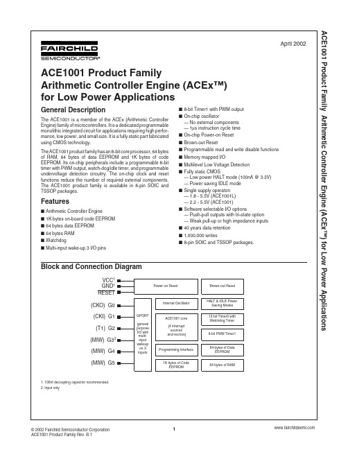
ACE1001 Product Family Arithmetic Controller Engine (ACEx™) for Low Power ApplicationsACE1001 Product Family Arithmetic Controller Engine (ACEx™) for Low Power ApplicationsACE1001 Product Family Arithmetic Controller Engine (ACEx™) for Low Power ApplicationsACE1001 Product Family Arithmetic Controller Engine (ACEx™) for Low Power ApplicationsACE1001 Product Family Arithmetic Controller Engine (ACEx™) for Low Power ApplicationsACE1001 Product Family Arithmetic Controller Engine (ACEx™) for Low Power ApplicationsACE1001 Product Family Arithmetic Controller Engine (ACEx™) for Low Power ApplicationsACE1001 Product Family Arithmetic Controller Engine (ACEx™) for Low Power ApplicationsACE1001 Product Family Arithmetic Controller Engine (ACEx™) for Low Power ApplicationsACE1001 Product Family Arithmetic Controller Engine (ACEx™) for Low Power ApplicationsACE1001 Product Family Arithmetic Controller Engine (ACEx ™) for Low Power ApplicationsACE1001 Product Family Arithmetic Controller Engine (ACEx ™) for Low Power ApplicationsACE1001 Product Family Arithmetic Controller Engine (ACEx ™) for Low Power ApplicationsACE1001 Product Family Arithmetic Controller Engine (ACEx ™) for Low Power ApplicationsACE1001 Product Family Arithmetic Controller Engine (ACEx ™) for Low Power ApplicationsACE1001 Product Family Arithmetic Controller Engine (ACEx ™) for Low Power ApplicationsACE1001 Product Family Arithmetic Controller Engine (ACEx ™) for Low Power ApplicationsACE1001 Product Family Arithmetic Controller Engine (ACEx ™) for Low Power ApplicationsACE1001 Product Family Arithmetic Controller Engine (ACEx ™) for Low Power ApplicationsACE1001 Product Family Arithmetic Controller Engine (ACEx ™) for Low Power Applications。
- 1、下载文档前请自行甄别文档内容的完整性,平台不提供额外的编辑、内容补充、找答案等附加服务。
- 2、"仅部分预览"的文档,不可在线预览部分如存在完整性等问题,可反馈申请退款(可完整预览的文档不适用该条件!)。
- 3、如文档侵犯您的权益,请联系客服反馈,我们会尽快为您处理(人工客服工作时间:9:00-18:30)。
TYPE ESR SURFACE MOUNT POLYMER ALUMINUM ELECTROLYTIC CAPACITORS.
Unlike solid tantalum, which can fail short and burn, type ESR capacitors in normal operation fail benignly as gradual open circuits after 25 to 50 years of operation.
The equivalent series resistance of these capacitors is much lower than for solid tantalum capacitors, thus you get much higher ripple current handling capability.
NOTE: Type ESR capacitors are not recommended for new design, and therefore, may be subject to larger than expected minimum order quantities. CDE capacitor Types ESRD, ESRE, and ESRL are recommended for new design, and can be used as replacements to upgrade existing designs that employ Type ESR capacitors. However, the ESRD, ESRE, and ESRL footprint is not compatible with the Type ESR footprint.
Specifications:
Type ESR SMT capacitors are polarized, aluminum capacitors which use a highly conductive solid polymer as the electrolyte.
They have reliability advantages over both
aluminum and solid tantalum electrolytic capacitors. Unlike aluminum capacitors, there is no liquid electrolyte to evaporate and cause failure.
Dimensions
Available Ratings:
greater)
Dissipations Factor (DF):
The ratio of the capacitor's equivalent series
resistance to its reactance. It's no more than 0.06 at 120Hz and +20°C.
Resistance to Soldering Heat:
Capacitors will withstand 30 sec onds at +240 ºC in a s
older-reflow oven.
Life Test:
Apply rated dc working voltage at 105°C for 1,000 hours and then stabilize to +20°C. Capacitors will meet the following limits:
Capacitance change shall not exceed ± 10% of the initial measured value.D.F. and D.C.L. shall not exceed the initial
specified value.Shelf Life Test:
Shelf life is typically 5 to 10 years. Accelerated test:after 500 hours at 105°C, capacitors will meet the following limits after stabilization at 20°C: Capacitance change shall not exceed ± 10% of the initial measured value.
D.F. and D.C.L. shall not exceed the initial specified value.
All product specifications, and all purchases of products from Cornell-Dubilier, are subject to its Terms and Conditions.
Capacitance
(µF)Catalog Number
Reel Quantity
Catalog Number
For Bulk Quantitites Less Than Full Reel Qty.
Maximum Ripple AMPS rms (at 100 kHz, +100°C )
4 Vdc 82.00ESR820M0G13162,200ESR820M0G000B 1.66.3 Vdc 10.00ESR100M0J15163,000ESR100M0J000B 1.022.00ESR220M0J15163,000ESR220M0J000B 1.333.00ESR330M0J15163,000ESR330M0J000B 1.647.00ESR470M0J15163,000ESR470M0J000B 1.668.00ESR680M0J13162,200ESR680M0J000B 1.68 Vdc 22.00ESR220M0K15163,000ESR220M0K000B 1.633.00ESR330M0K15163,000ESR330M0K000B 1.647.00ESR470M0K13162,200ESR470M0K000B 1.612.
5 Vdc 10.00ESR100M1B15163,000ESR100M1B000B 1.022.00ESR220M1B15163,000ESR220M1B000B 1.633.00ESR330M1B13162,200ESR330M1B000B 1.61
6 Vdc 4.70ESR4R7M1C15163,000ESR4R7M1C000B 1.06.80ESR6R8M1C15163,000ESR6R8M1C000B 1.010.00
ESR100M1C1516
3,000
ESR100M1C000B
1.3
Tel# 508-996-8564Fax# 508-996-3830。
