RCH1216BNP-390M中文资料
RCH1216BNP-470M中文资料

仕 様 書形 名RCH1216B1.外形* 端子の寸法は、はんだつらら除く。
1-2.捺印表示例頭部直捺印捺印位置不定 2.コイル仕様 2-1.端子接続図(裏面図)(10μH~47μH) (56μH~2.2mH)* 10μH~47μHは、端子番号①と④、②と③を接続して御使用ください。
* 10μH~47μHは、端子②-③間又は①-④間の半田ブリッジが可とする。
①②③④①②③ compliance Cd:Max.0.01wt%others:Max.0.1wt%RoHS1仕 様 書形 名RCH1216B2-2.電気的特性直流重畳 許容電流 (A) ※3No. 品 名表示 インダクタンス[以内]※1D.C.R. (Ω) [以下] (at 20℃)※2 at 20℃at 100℃ 温度上昇許容電流 (A) ※4 スミダコード01 RCH1216BNP-1ØØM 100M 10μH ±20%24m(19m) 9.00 8.00 5.00 -000102 RCH1216BNP-12ØM 120M 12μH ±20%26m(21m) 7.80 7.00 4.60 -000203 RCH1216BNP-15ØM 150M 15μH ±20%29m(23m) 7.20 6.20 4.40 -000304 RCH1216BNP-18ØM 180M 18μH ±20%33m(26m) 6.75 5.80 4.20 -000405 RCH1216BNP-22ØM 220M 22μH ±20%37m(29m) 6.00 5.30 4.00 -000506 RCH1216BNP-27ØM 270M 27μH ±20%41m(32m) 5.50 4.80 3.80 -000607 RCH1216BNP-33ØM 330M 33μH ±20%46m(36m) 5.00 4.50 3.60 -000708 RCH1216BNP-39ØM 390M 39μH ±20%49m(39m) 4.70 4.10 3.30 -000809 RCH1216BNP-47ØM 470M 47μH ±20%56m(44m) 4.30 3.80 3.20 -000910 RCH1216BNP-56ØK 560K 56μH ±10%87m(69m) 4.10 3.70 2.70 -001011 RCH1216BNP-68ØK 680K 68μH ±10%98m(78m) 3.80 3.30 2.40 -001112 RCH1216BNP-82ØK 820K82μH ±10%107m(85m) 3.20 2.90 2.25 -001213 RCH1216BNP-1Ø1K 101K 100μH ±10%121m(96m) 3.00 2.70 2.15 -001314 RCH1216BNP-121K 121K 120μH ±10%134m(107m) 2.85 2.60 2.05 -001415 RCH1216BNP-151K 151K 150μH ±10%156m(124m) 2.55 2.35 1.90 -001516 RCH1216BNP-181K 181K 180μH ±10%206m(164m) 2.20 2.05 1.65 -001617 RCH1216BNP-221K 221K 220μH ±10%236m(188m) 2.00 1.85 1.55 -001718 RCH1216BNP-271K 271K 270μH ±10%0.32(0.25) 1.85 1.70 1.40 -001819 RCH1216BNP-331K 331K 330μH ±10%0.37(0.29) 1.65 1.53 1.30 -001920 RCH1216BNP-391K 391K 390μH ±10%0.48(0.38) 1.55 1.35 1.05 -002021 RCH1216BNP-471K 471K 470μH ±10%0.55(0.44) 1.45 1.25 1.00 -002122 RCH1216BNP-561K 561K 560μH ±10%0.62(0.49) 1.36 1.18 0.95 -002223 RCH1216BNP-681K 681K 680μH ±10%0.79(0.63) 1.20 1.06 0.82 -002324 RCH1216BNP-821K 821K 820μH ±10%0.88(0.70) 1.14 0.97 0.75 -002425 RCH1216BNP-1Ø2K 102K 1.0mH ±10% 1.13(0.90) 1.00 0.80 0.65 -002526 RCH1216BNP-122K 122K 1.2mH ±10% 1.25(1.00)0.89 0.76 0.61 -002627 RCH1216BNP-152K 152K 1.5mH ±10% 1.52(1.26)0.85 0.70 0.54 -002728 RCH1216BNP-182K 182K 1.8mH ±10% 1.93(1.60)0.76 0.63 0.46 -002829 RCH1216BNP-222K 222K2.2mH ±10%2.52(2.10)0.650.570.41-0029※1 測定周波数 インダクタンス at 1kHz ※2 ( )内は、標準値とする。
纳尔森Type CLT自调节加热电缆说明书

• A standard option UV stabilized polyolefin over jacket is available to cover the braid for wet applications.
-29 (-20) 65 (205) 85 (275) 90 (290) 90 (290) 125 (415) 170 (550) 175 (580) 175 (580) 175 (580)
10 (50) 70 (220) 70 (225) 70 (225) 70 (225) 135 (445) 135 (450) 135 (450) 135 (450) 135 (450)
Operating Principle
• The parallel bus wires apply voltage along the entire length of the heater cable.
• The conductive core provides an infinite number of parallel conductive paths permitting the cable to be cut to any length in the field with no dead or cold zones developing.
Accessories
• Nelson PLT and AX Series Connection Kits for Power, Splice, Tee Splice, Powered Splices and End Terminations
FMMT3906中文资料

ELECTRICAL CHARACTERISTICS (at Tamb = 25°C unless otherwise stated).
FMMT3906. UNIT CONDITIONS. MAX V V V -50 -50 nA nA IC=-10µ A, IE=0 IC=-1mA, IB=0* IE=-10µ A, IC=0 VCE=-30V, VBE(off) =-3V VCE=-30V, VEB(off) =-3V IC=-0.1mA, VCE=-1V* IC=-1mA, VCE=-1V* IC=-10mA, VCE=-1V* IC=-50mA, VCE=-1V* IC=-100mA, VCE=-1V* V V IC=-10mA, IB=-1mA* IC=-50mA, IB=-5mA* IC=-10mA, IB=-1mA* IC=-50mA, IB=-5mA* -40 -40 -5 MAX MIN
fT
MHz IC=-10mA, VCE=-20V f=100MHz pF pF dB VCB=-5V, IE=0, f=100KHz VBE=0.5V, IC=0, f=100KHz IC=-200mA, VCE=-5V Rg=2kΩ , f=30Hz to 15kHz at -3dB points
FMMT3905 FMMT3906
C B E
COMPLEMENTARY TYPES -
ABSOLUTE MAXIMUM RATINGS.
PARAMETER Collector-Base Voltage CollectorEmitter Voltage Emitter-Base Voltage Continuous Collector Current Power Dissipation at Tamb=25°C Operating and Storage Temperature Range PARAMETER SYMBOL FMMT3905 MIN BreakdownVoltages V(BR)CBO V(BR)CEO V(BR)EBO Cut-Off Currents Static Forward Current Transfer Ratio ICEX IBEX hFE 30 40 50 30 15 -40 -40 -5 -50 -50 60 80 100 60 30 SYMBOL VCBO VCEO VEBO IC Ptot Tj:Tstg VALUE -40 -40 -5 -200 330 -55 to +150 UNIT V V V mA mW °C
FMB3906中文资料

FFB3906 / FMB3906 / MMPQ3906C1B2E2C1E1C2B1E2B2pin #1PNP Multi-Chip General Purpose Amplifier1998 Fairchild Semiconductor CorporationSuperSOT -6Mark: .2ASOIC-16Mark: MMPQ3906C1C1C2C2C3C3C4C4E1B1E2B2E3B3E4B4pin #1TRADEMARKSACEx™CoolFET™CROSSVOLT™E 2CMOS TM FACT™FACT Quiet Series™FAST ®FASTr™GTO™HiSeC™The following are registered and unregistered trademarks Fairchild Semiconductor owns or is authorized to use and is not intended to be an exhaustive list of all such trademarks.LIFE SUPPORT POLICYFAIRCHILD’S PRODUCTS ARE NOT AUTHORIZED FOR USE AS CRITICAL COMPONENTS IN LIFE SUPPORTDEVICES OR SYSTEMS WITHOUT THE EXPRESS WRITTEN APPROV AL OF FAIRCHILD SEMICONDUCTOR CORPORA TION.As used herein:ISOPLANAR™MICROWIRE™POP™PowerTrench™QS™Quiet Series™SuperSOT™-3SuperSOT™-6SuperSOT™-8TinyLogic™1. Life support devices or systems are devices or systems which, (a) are intended for surgical implant intothe body, or (b) support or sustain life, or (c) whosefailure to perform when properly used in accordancewith instructions for use provided in the labeling, can be reasonably expected to result in significant injury to the user.2. A critical component is any component of a lifesupport device or system whose failure to perform can be reasonably expected to cause the failure of the life support device or system, or to affect its safety or effectiveness.PRODUCT STATUS DEFINITIONS Definition of Terms Datasheet Identification Product Status DefinitionAdvance InformationPreliminary No Identification Needed Obsolete This datasheet contains the design specifications for product development. Specifications may change in any manner without notice.This datasheet contains preliminary data, andsupplementary data will be published at a later date.Fairchild Semiconductor reserves the right to make changes at any time without notice in order to improve design.This datasheet contains final specifications. Fairchild Semiconductor reserves the right to make changes at any time without notice in order to improve design.This datasheet contains specifications on a product that has been discontinued by Fairchild semiconductor.The datasheet is printed for reference information only.Formative or In DesignFirst ProductionFull ProductionNot In ProductionDISCLAIMERFAIRCHILD SEMICONDUCTOR RESERVES THE RIGHT TO MAKE CHANGES WITHOUT FURTHER NOTICE TO ANY PRODUCTS HEREIN TO IMPROVE RELIABILITY , FUNCTION OR DESIGN. FAIRCHILD DOES NOT ASSUME ANY LIABILITY ARISING OUT OF THE APPLICATION OR USE OF ANY PRODUCT OR CIRCUIT DESCRIBED HEREIN; NEITHER DOES IT CONVEY ANY LICENSE UNDER ITS PATENT RIGHTS, NOR THE RIGHTS OF OTHERS.UHC™VCX™。
3906;中文规格书,Datasheet资料
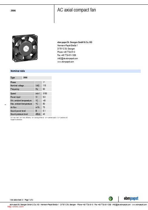
Mass Dimensions Material of impeller Housing material Direction of air flow Direction of rotation Bearing Lifetime L10 at 40 °C Lifetime L10 at maximum temperature Connection line Motor protection Approval
3906
AC axial compact fan
ebm-papst St. Georgen GmbH & Co. KG Hermann-Papst-Straße 1 D-78112 St. Georgen Phone +49 7724 81-0 Fax +49 7724 81-1309 info2@
Web data sheet XI · Page 2 of 4 ebm-papst St. Georgen GmbH & Co. KG · Hermann-Papst-Straße 1 · D-78112 St. Georgen · Phone +49 7724 81-0 · Fax +49 7724 81-1309 · info2@ ·
/
3906
AC axial compact fan
Charts: Air flow
(in H ² O) 0,05 0,10 0,15 0,20
∆ pf ä
60 50 40 30 20 10
0
10
20
30
CFM
Vä
•
10
20
30
40
50
60
m³/h
海尔电器 1 CAT2125 扭矩钳 操作说明书

• Anticipate and be alert for sudden changes in motion during start up and operation of any power tool.
• Do not force tool beyond its rated capacity. • Do not remove any labels. Replace any
damaged labels.
Rev. 09/ctions • Warning Information • Parts Breakdown
• Operators and maintenance personnel must be physically able to handle the bulk, weight and power of this tool.
• Air under pressure can cause severe injury. Never direct air at yourself or others. Always turn off the air supply, drain hose of air pressure and detach tool from air supply before installing, removing or adjusting any accessory on this tool, or before performing any maintenance on this tool. Failure to do so could result in injury. Whip hoses can cause serious injury. Always check for damaged, frayed or loose hoses and fittings, and replace immediately. Do not use quick detach couplings at tool. See instructions for correct set-up.
德国马尔放大器c1216中文说明书

Operating Instructions操作说明Millimar C1208/C1216MAHR GMBH•GERMANY•MAHR FEDERAL INC.•U.S.A.德国马尔精密量具量仪湖北武汉授权代理商武汉科赛思机电有限公司提供目录*根据最新程序操作软件修订,软件版本号:V1.01-020初始运行.........................................................211密码保护 (23)1基本要点.........................................................412进行测量 (24)2控制原理.........................................................512.1进行合计测量 (24)3基本设置.........................................................812.2进行差值测量 (25)3.1选择屏幕语言................................................812.3进行径向圆跳动测量 (26)3.2设置对比度...................................................813测量值存贮 (27)3.3设置测量单位................................................814使用串行接口(RS232) (28)3.4设置测量值的分辨率/显示格式...........................914.1选择接口协议 (28)3.5选择显示的数字特性/测试结果...........................914.2选择数据传输格式 (29)4测量设备的测头定位(安装)..............................1014.3选择信息交换 (29)5校正测头灵敏度.............................................1014.4选择传输速度 (30)5.1校准通道C1的测头灵敏度..............................1114.5选择传输频率 (30)5.2根据通道C1的测头灵敏度校正通道C2的测头(只用14.6接口配置实例 (31)于连接电感测头的设备).......................................1114.6.1数据传输至计算机时的接口配置 (31)6设置特性1的计算及显示.................................1214.6.2数据传输至计算机时的接口配置 (31)6.1设置某一特性的准确显示值的因子..................12M1240接口协议 (31)6.2选择单个通道或通道连接方案(公式)..................13OPTORSD接口协议 (33)7选择一个特性................................................13OPTORSS接口协议 (34)8标准尺寸测量................................................14MARTALK接口协议 (34)8.1怎样选择标准尺寸测量的类型........................1614.7使用一条0-模式线连接至PC(配线图) (35)8.2输入一点标准尺寸测量的名义标准尺寸值.........1615使用并行(I/0)接口 (35)8.3输入两点标准尺寸测量的名义标准尺寸值.........1615.1数字式输出控制端 (35)8.4执行一点标准尺寸测量.................................1715.2数字式输入控制端 (36)8.5执行两点标准尺寸测量.................................1715.3数字式控制输入及输出端应用实例 (37)9设置公差及极限值..........................................1715.4模拟输出端(仅针对C1216!) (39)9.1设置公差极限.............................................1715.4.1选择被显示的特性 (39)9.2设置报警极限.............................................1815.4.2设置模拟信号输出的灵敏度 (40)9.3为报警及公差极限设置状态灯的颜色...............1916恢复出厂设置 (40)9.4设置有效极限.............................................1917出错提示信息 (4110)设置测量值记录参数.......................................2018技术参数 (42)10.1设置滤波参数.............................................2019Mahr联络方式 (43)10.2指定测量顺序.............................................2120质保 (44)10.3操作模式“NORMAL”....................................2121索引 (44)10.4操作模式“AUTOM.”.......................................2222功能及参数菜单操作 (44)10.5输入一个启动延时 (22)在操作说明中,你将看到以下图标:普通信息重要信息。
M12H6DC 60-90GHz放大器规格说明书

Extended WR-12 Harmonic Mixer Module, 56 to 96 GHz, with 2 ea. SMA(m)/SMA(f) Adapter
M12H6DC5696-103
Extended WR-12, 56 to 96 GHz, Harmonic Mixer Module, 56 to 96 GHz, with 2 ea. SMA(m)/SMA(f) Adapter & a WR-12 24 dBi Horn Antenna
DESCRIPTION
The M12H6DC Series is designed specifically for handheld spectrum analyzers as a portable solution for millimeter wave spectrum analysis measurement. Utilizing the handheld spectrum analyzer tracking generator as an LO source and the built-in DC supply, this harmonic mixer provides millimeter wave measurements in WR-12 (60-90 GHz).
M12H6DC5696-104
Extended WR-12, 56 to 96 GHz, Harmonic Mixer Module, 56 to 96 GHz, with 2 ea. SMA(m)/2.4mm(f) Adapter
M12H6DC5696-105
Extended WR-12, 56 to 96 GHz, Harmonic Mixer Module\, 56 to 96 GHz, with 2 ea. SMA(m)/2.4mm(f) Adapter & a WR-12 24 dBi Horn Antenna
NCP1216中文资料

• High Power AC−DC Converters for TVs, Set−Top Boxes, etc. • Offline Adapters for Notebooks • Telecom DC−DC Converters • All Power Supplies
1
September, 2004 − Rev. 8
Publication Order Number: NCP1216/D
元器件交易网
NCP1216, NCP1216A
+
*See Application Section
EMI Filter
Universal Input
NCP1216
Current 3 Sense
GND 4
220 ns L.E.B 19 k
Ramp
20 k
Compensation
Pull−up Resistor 57 k
+ −
Vref
25 k
5V
65 kHz 100 kHz 133kHz
Set Q Flip−Flop Q DCmax = 75%
Reset
+ −
1V
4
GND
IC Ground
−
5
Drv
Driving Pulses
The driver’s output to an external MOSFET.
6
VCC
7
NC
Supplies the IC −
This pin is connected to an external bulk capacitor of typically 22 mF. This un−connected pin ensures adequate creepage distance.
RC12-6-01中文资料
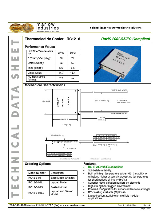
.002 [0.05] HOT SIDE, Th -01 & -01S -01L & -01LS .158 ±.005 [4.01±0.13] .154 ±.001 [3.91±0.03] Ceramic Material: Alumina (AC)
.001 [0.03] A
Dimensions in [ ] are millimeters
Features
• • • • • • • • RoHS 2002/95/EC compliant Solid-state reliability. Built with high temperature solder with the ability to withstand higher assembly processing temperatures for short periods of time (<160°C). Superior nickel diffusion barriers on elements High strength for rugged environment. Porched configuration for enhanced leadwire strength RTV sealing available (Optional) Lapped option available for multiple module applications. Doc # 102-0278 Rev A
Ordering Options
Model Number RC12-6-01 RC12-6-01L RC12-6-01S RC12-6-01LS Description Base Model w/ leads Lapped Model Sealed Model Lapped and Sealed Model
海尔生锂无金质紧密管系列用户指南说明书

—Features & Benefits:• Meets UL 514B and CSA C22.2, No. 18.3 for liquid-tight fittings• Full compliance to IEC 61386-1, -23 requirements, CE Certified• Trade sizes from 3/8” to 4” (12mm to 103mm)• Straight and 90° conduit bodies• NPT Threads• Coordinated performance with T&B Liquidtight Systems Flexible Metallic Conduits• Ingress protection ratings aligned with industrial enclosures• Safe Edge®, zinc plated steel ground cones provides superior bonding• Double Bevel Sealing Ring eases assembly and insures liquid-tight performance• Revolver® grounding version with GR part number suffix—Applications:• Typical applications include raceway for industrial and commercial applications such as suspended electrical systems, corrosive environments and portable equipment, where light weight requirements must be met• Ideal for use with LTAE and LTLE aluminum LT Flexible Metallic Conduits• Used where liquid-tight flexible metallic raceway is installed in outdoor or indoor locations, and exposed to continuous or intermittent moisture• Used to positively bond flexible liquid-tight flexible metallic conduit to boxes or enclosures • Liquid-tight applications against water, oils, cutting fluids, mild acids• For use in electrical circuits up to 1,000 V• Suitable for use in Class 1 Division 2, Class 2 Division 1 & 2 Hazardous Locations perNEC® Section 500—Construction / Material / Finish:• Trade sizes 3/8” to 4” Copper-Free Aluminum• Zinc plated steel ground cones• Thermoplastic Nylon sealing rings• Halogen Free seal rings• Aluminum Cast Locknuts with teeth for vibration resistance—Environment ratings:Working Temperature:• UL: Gen: -20 to +105°C (-4 to +221°F)• CSA: Gen: -20 to +105°C (-4 to +221°F)• IEC/CE: Gen: -25 to +105°C (-13 to +221°F)—Chemical Resistance Guide:• See Publication TDS000081 (Fittings: Aluminum & PA66 Polyamide)• See Publication TDS000117 (Liquid-tight Flexible Metal Conduits)—Conforms to:• UL 514B, Fittings for Cable and Conduit–File: E23018• CSA C22.2, No. 18.3, Outlet and Conduit Boxes, Fittings and Accessories–File: LR-4484• IEC/EN 61386-1, -23, Conduit Systems for Cable Management–EU DoC: EC-012-7187• RoHS (Restriction of Hazardous Substance directive)• NEMA FB-1 (Fittings and Conduit Bodies)• JIC EGP1 (Electrical standard for GP machine tools)• JIC EMP1 (Electrical Standard for Mass Production Engineering)• Federal Specification A-A 50552 (Fittings for flexible conduit)• Federal Specification H-28 (Threads)—Ingress Protection:• Provides “Ingress Integrity” between enclosures, fittings, conduits & seals when using Series 5200AL liquid-tight fittings and T&B Liquidtight Systems LFMC• Covers all trade sizes from 3/8” to 4” (12mm to 103mm)• Ingress ratings require use of Series 5260 Seal GasketsUL, CSA & NEMA system ingress ratings:• 5200AL UL Listed type ratings tested to UL 50E requirements with UL Listed LFMC• UL File No.: E23018–Indoor: Type 4, 12, 13–Outdoor: Type 3, 3R, 4• CSA C22.2, No. 94.2: Type 3, 3R, 4, 12, 13• NEMA 250: Type 3, 3R, 4, 12, 13IEC system ingress ratings:• IP Ingress Protection per IEC/EN EC 60529 requirements• IEC Ingress Ratings: IP66, IP67—Standards requirements:Designed to UL 514B and CSA C22.2, No. 18.3 test requirements including:• Assembly, Pull, Resistance, Oil spray, Polymer durability, Flammability coating thickness, Current withstandMeets all IEC/EN 61386-1, -23 standard requirements including:• Impact resistance - Code 3 Medium; 6 Joules• Tensile strength - Code 3 Medium; 500 N/2 min.• Lower and upper temperatures• IP protection against solid and liquidsAluminum Liquid-tight fittings areideal for use in corrosive environ-ments and where light weightconduit systems are required.Certifications / Standards:1—TECHNICAL DATA SHEETLiquid-tight fittings - Series 5200AL Aluminum For liquid-tight flexible metallic conduit• Dimensions for reference only.• Product must be installed in accordance with applicable national and local electrical codes.—We reserve the right to make technical changes or modify the contents of this document without prior notice. With re-gard to purchase orders, the agreed par-ticulars shall prevail. ABB Inc. does not ac-cept any responsibility whatsoever for potential errors or possible lack of infor-mation in this document.We reserve all rights in this document and in the subject matter and illustrations con-tained therein. Any reproduction, disclo-sure to third parties or utilization of its contents – in whole or in parts – is forbidden without prior written consent of ABB Inc. Copyright© 2018 ABB Inc.All rights reservedLet’s write the future.Together. S e r i e s 5200A L | T e c h n i c a l d a t a s h e e t | T D S 000118 A—ABB Inc.Electrification products Memphis, Tennessee USA2。
CNI16系列温度、过程和扭矩控制器商品说明书

CNI1633-AL CNI16D33M-9Temperature, Process andStrain ControllersCNi32, shown smaller than actual size.CNi16, shownsmaller than actual size.CNi8, shown smaller than actual size.CNi8DV , shown smallerthan actual size.CNi SeriesU U niversal Inputs U H igh Accuracy: 0.5°C (±0.9°F), 0.03% Reading U T otally Programmable Color Displays (Visual Alarms)U U ser-Friendly, Simple to Configure U F ree Software U F ull Autotune PID Control U E mbedded Internet Connectivity Optional UR S232 and RS485 Serial Communications Optional U B uilt-In Excitation U 2 Control/Alarm Outputs; Choice of DC, Pulse, Solid State Relays, Mechanical Relays, Analog Voltage and Current U O utput 3 Retransmission: Isolated Analog Voltage and Current Optional U N EMA 4 (IP65) Front Bezel U T emperature Stability ±0.04°C/°C RTD and±0.05°C/°C Thermocouple @ 25°C (77°F)U F ront Removable and Plug ConnectorsU AC or DC Powered Units U R atiometric Mode for Strain Gages U P rogrammableDigital FilterThe OMEGA ® iSeries is a family of microprocessor-based instruments offered in three true DIN sizes.All of the instruments share the same set-up and configuration menu and method of operation, a tremendous time saver for integration of a large system. The iSeries family includes extremely accurate digital panel meters “DPi” and single loop PID controllers “CNi” that are simple to configure and use, while providing tremendous versatility and a wealth of powerful features.The CNi Series covers a broad selection of transducer andtransmitter inputs with 2 input models.The Universal temperature and process instrument (CNi models) handles 10 common types ofthermocouples, multiple RTDs and several process (DC) voltage and current ranges. This model alsofeatures built-in excitation, 24 Vdc @ 25 mA. With its wide choice of signal inputs, this model is an excellent choice for measuring or controlling temperature with a thermocouple, RTD, or 4 to 20 mA transmitter. The strain and process instruments (CNiS models) measure inputs from load cells, pressure transducers, and most any strain gage sensor as well as process voltage and current ranges. The CNiS has built-in 5 or 10 Vdc excitation for bridge transducers, 5 Vdc @ 40 mA or 10 Vdc @ 60 mA (any excitation voltage between 5 and 24 Vdc is available by special order). This CNiS model supports 4- and 6-wire bridge communications, ratiometric measurements. The CNiS features fast and easy “in process” calibration/scaling of the signal inputs to any engineering units. This model also features 10-point linearization whichallows the user to linearize the signal input from extremely nonlinear transducers of all kinds.Control FunctionsThe iSeries can control simple manual operation to ON-OFF and full Autotune PID control. (Selectable preset tune, adaptive tune, PID, PI, PD control modes.) The dual control outputs can be configured for a variety of independent control and alarm applications such as heat/heat, heat/cool, heat/alarm, cool/cool, cool/alarm or alarm/alarm. The ramp to setpoint feature allows the user to define the rate of rise to setpoint, minimizing thermal shock to the load during start-up. Forapplications that do not require PID control, just simplified programming, there are 2 options available: -AL Limit Alarm and -SM Simplified Menu ON-OFF control.Programmable Color DisplayThe iSeries are 1⁄8, 1⁄16 and 1⁄32 DIN controllers featuring the big iSeries color-changing display. The digits are twice the size of typical 1⁄8 DIN panel meters. The iSeries feature the only LED displays that can be programmed to change color between GREEN , AMBER , and RED .Embedded Internet and Serial CommunicationsFeaturing optional “embeddedInternet” the iSeries connect directly to an Ethernet network and transmit data in standard TCP/IP packets, or serve Web pages over a LAN or the Internet. The iSeries are also available with serial communications. The user can select from the pushbutton menu between RS232, RS422, and RS485, with straightforward ASCII commands or MODBUS.M-10Ordering Examples: CNi3233-C24-DC, 1⁄32 DIN temperature/process meter with two relay outputs plus RS232 and RS485 and 12 to 36 Vdc power supply.CNi16D22-EIT, 1⁄16 DIN dual display temperature/process meter with two SSR outputs plus ethernet with embedded web server.*2 “-DC ”, “-C24”, and “-C4EIT ” not available with excitation.*3 Analog output is not available with “-AL ” units.*4 CNi8A0x-AL or CNi16A0x-AL contains 1 alarm and 1 analog retransmission.*5 “-SM ” option not available on CNiS strain models.Universal Temperature andProcess Input (DPi/CNi Models)Accuracy: ±0.5°C temp; 0.03% rdg Resolution: 1°/0.1°; 10 µV process Temperature Stability: RTD: 0.04°C/°CTC @ 25°C (77°F): 0.05°C/°C Cold Junction Compensation Process: 50 ppm/°C NMRR: 60 dB CMRR: 120 dBA/D Conversion: Dual slope Reading Rate: 3 samples/s Digital Filter: ProgrammableDisplay: 4-digit 9-segment LED 10.2 mm (0.40"); i32, i16, i16D, i8DV 21 mm (0.83"); i8 10.2 mm (0.40") and 21 mm (0.83"); i8DH RED , GREEN, and AMBER programmable colors for process variable, setpoint and temperature unitsInput Types: Thermocouple, RTD, analog voltage, analog currentThermocouple Lead Resistance: 100 Ω maxThermocouple Types (ITS 90): J, K, T, E, R, S, B, C, N, L (J DIN)RTD Input (ITS 68): 100/500/1000 Ω Pt sensor, 2-, 3- or 4-wire; 0.00385 or 0.00392 curveVoltage Input: 0 to 100 mV, 0 to 1V, 0 to 10 VdcInput Impedance: 10 M Ω for 100 mV 1 M Ω for 1 or 10 VdcCurrent Input: 0 to 20 mA (5 Ω load)Configuration: Single-ended Polarity: UnipolarStep Response: 0.7 sec for 99.9%Decimal Selection:Temperature: None, 0.1Process: None, 0.1, 0.01 or 0.001Setpoint Adjustment: -1999 to 9999 counts Span Adjustment: 0.001 to 9999 countsOffset Adjustment: -1999 to 9999Excitation (Not Included withCommunication): 24 Vdc @ 25 mA (not available for low-power option)Universal Strain and Process Input (DPiS/CNiS Models)Accuracy: 0.03% reading Resolution: 10/1µVTemperature Stability: 50 ppm/°C NMRR: 60 dB CMRR: 120 dBA/D Conversion: Dual slope Reading Rate: 3 samples/s Digital Filter: ProgrammableInput Types: Analog voltage and current Voltage Input: 0 to 100 mVdc, -100 mVdc to 1 Vdc, 0 to 10 VdcInput Impedance: 10 M Ω for 100 mV;1 M Ω for 1V or 10 Vdc Current Input: 0 to 20 mA (5 Ω load)Linearization Points: Up to 10 Configuration: Single-ended Polarity: UnipolarStep Response: 0.7 sec for 99.9%Decimal Selection: None, 0.1, 0.01 or 0.001Setpoint Adjustment: -1999 to 9999 countsSpan Adjustment: 0.001 to 9999 counts Offset Adjustment: -1999 to 9999Excitation (Optional In Place Of Communication): 5 Vdc @ 40 mA;10 Vdc @ 60 mAControlAction: Reverse (heat) or direct (cool)Modes: Time and amplitude proportional control; selectable manual or auto PID, proportional, proportional with integral, proportional with derivative and anti-reset Windup, and on/off Rate: 0 to 399.9 s Reset: 0 to 3999 sCycle Time: 1 to 199 s; set to 0 for on/off Gain: 0.5 to 100% of span; setpoints 1 or 2Damping: 0000 to 0008Soak: 00.00 to 99.59 (HH:MM), or OFF Ramp to Setpoint:00.00 to 99.59 (HH:MM), or OFFAuto Tune: Operator initiated from front panelControl Output 1 and 2Relay: 250 Vac or 30 Vdc @ 3 A (resistive load); configurable for on/off, PID and ramp and soakOutput 1: SPDT, can be configured asalarm 1 outputOutput 2: SPDT, can be configured asalarm 2 outputSSR: ******************.5A (resistive load); continuous DC Pulse: Non-isolated; 10 Vdc @ 20 mA Analog Output (Output 1 Only):Non-isolated, proportional 0 to 10 Vdc or 0 to 20 mA; 500 Ω maxOutput 3 RetransmissionIsolated Analog Voltage and CurrentCurrent: 10 V max @ 20 mA outputVoltage: 20 mA max for 0 to 10 V outputNetwork and Communications Ethernet: Standards compliance IEEE 802.3 10 Base-T Supported Protocols: TCP/IP, ARP, HTTPGET RS232/RS422/RS485: Selectable frommenu; both ASCII and MODBUS protocol selectable from menu; programmable 300 to 19.2 Kb; complete programmable setup capability; program to transmit current display, alarm status, min/max, actual measured input value and status Common Specifications (Alli/8, i/16, i/32 DIN)RS485: Addressable from 0 to 199Connection: Screw terminalsAlarm 1 and 2 (Programmable)Type: Same as output 1 and 2Operation: High/low, above/below, band, latch/unlatch, normally open/normally closed and process/deviation; front panel configurationsAnalog Output (Programmable):Non-isolated, retransmission 0 to 10 Vdc or 0 to 20 mA, 500 Ω max (output 1 only); accuracy is ± 1% of FS when following conditions are satisfied: input is not scaled below 1% of input FS, analog output is not scaled below 3% of output FSGeneralPower: 90 to 240 Vac ±10%, 50 to 400 Hz *, 110 to 375 Vdc, equivalent voltage Low Voltage Power Option: 24 Vac **, 12 to 36 Vdc for DPi/CNi/DPiS/CNiS; 20 to 36 Vdc for dual display, ethernet and isolated analog output from qualified safety approved sourceIsolationPower to Input/Output: 2300 Vac per 1 minute testFor Low Voltage Power Option: 1500 Vac per 1 minute test Power to Relay/SSR Output: 2300 Vac per 1 minute testRelay/SSR to Relay/SSR Output: 2300 Vac per 1 minute test RS232/485 to Input/Output: 500 Vac per 1 minute test Environmental Conditions:All Models: 0 to 55°C (32 to 131°F)90% RH non-condensing Dual Display Models:0 to 50°C (32 to 122°F), 90% RHnon-condensing (for UL only) Protection: D Pi/CNi/DPiS/CNiS32, i16, i16D, i8C: NEMA 4X/Type 4 (IP65) front bezel DPi/CNi8, CNi8DH, i8DV: NEMA 1/Type 1 front bezelApprovals: UL, C-UL, CE per EN61010- 1:2001, FM (temperature units only)Dimensionsi /8 Series: 48 H x 96 W x 127 mm D(1.89 x 3.78 x 5") i/16 Series: 48 H x 48 W x 127 mm D (1.89 x 1.89 x 5")i/32 Series: 25.4 H x 48 W x 127 mm D(1.0 x 1.89 x 5")Panel Cutouti /8 Series: 45 H x 92 mm W(1.772 x 3.622"), 1⁄8 DIN i/16 Series: 45 mm (1.772") square,1⁄16 DINi/32 Series: 22.5 H x 45 mm W(0.886 x 1.772"), 1⁄32 DIN Weight i /8 Series: 295 g (0.65 lb) i/16 Series: 159 g (0.35 lb) i/32 Series: 127 g (0.28 lb)* No CE compliance above 60 Hz. ** Units can be powered safely with 24 Vacpower, but no certification for CE/UL are claimed.M-11CNI1633-AL CNI16D33。
台诺科变频器说明书

台诺科变频器说明书一、产品介绍台诺科变频器是一种高性能的电气控制设备,广泛应用于工业生产中的电机驱动系统。
该变频器通过调整电源频率来控制电机的转速,实现对电机运行状态的精确控制。
台诺科变频器具有稳定、可靠、高效节能等特点,是提高生产效率、降低能耗的重要装备。
二、产品特点1. 高精度控制:台诺科变频器采用先进的控制算法和数字信号处理技术,能够实现对电机运行状态的精确控制,使其在不同负载条件下保持稳定的转速。
2. 宽频调节范围:台诺科变频器的频率调节范围广泛,可以根据实际需求进行精细调节,适用于各种不同的工作场景。
3. 高效节能:台诺科变频器采用先进的功率调节技术,能够根据实时负载情况自动调整电源频率,最大限度地降低能耗,提高能源利用效率。
4. 多种保护功能:台诺科变频器具有过电流、过载、过热等多种保护功能,能够有效保护电机和变频器本身,延长设备的使用寿命。
5. 界面友好:台诺科变频器采用人机界面设计,操作简单方便,显示清晰直观,能够及时反馈电机运行状态和故障信息。
三、安装与调试1. 安装要求:在安装台诺科变频器时,需要选择一个通风良好、无腐蚀性气体和灰尘的环境,确保设备正常运行。
2. 接线方法:按照变频器的接线图,正确连接电源线、电机线和控制信号线,确保接线牢固可靠。
3. 参数设置:根据实际需求,通过变频器的参数设置功能,设置合适的频率范围、转速、保护功能等参数。
4. 检查与调试:在安装完成后,进行设备的检查与调试工作,确保各项功能正常运行,避免潜在故障的发生。
四、操作与维护1. 启动与停止:按照台诺科变频器的启动与停止流程,正确操作设备,避免因操作不当导致的故障。
2. 运行监测:通过台诺科变频器的人机界面,实时监测电机的运行状态,包括电流、转速、温度等参数,及时发现异常情况并进行处理。
3. 维护保养:定期对台诺科变频器进行维护保养工作,包括清洁设备、检查接线、紧固螺丝等,确保设备的正常运行。
4. 故障排除:在变频器出现故障时,根据设备手册提供的故障代码和排除方法,进行故障诊断与处理,确保设备的及时修复。
MG160390-WD型交流电牵引采煤机说明书
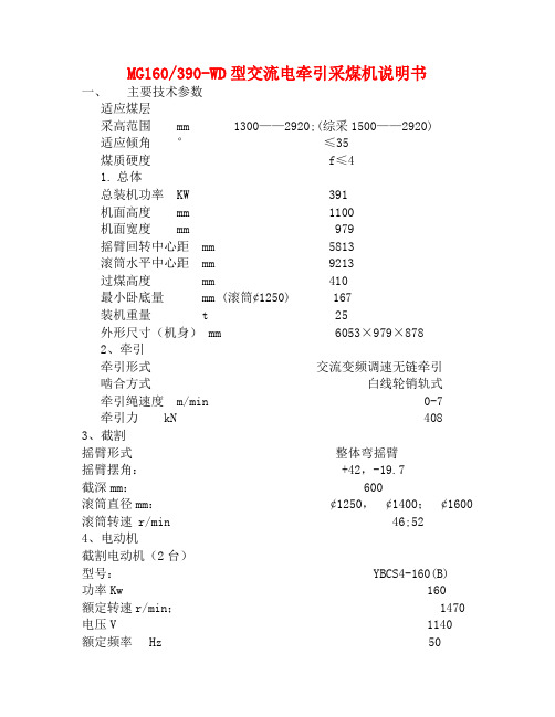
MG160/390-WD型交流电牵引采煤机说明书一、主要技术参数适应煤层采高范围 mm 1300——2920;(综采1500——2920)适应倾角°≤35煤质硬度 f≤41.总体总装机功率 KW 391机面高度 mm 1100机面宽度 mm 979摇臂回转中心距 mm 5813滚筒水平中心距 mm 9213过煤高度 mm 410最小卧底量 mm (滚筒¢1250) 167装机重量 t 25外形尺寸(机身) mm 6053×979×8782、牵引牵引形式交流变频调速无链牵引啮合方式白线轮销轨式牵引绳速度 m/min 0-7牵引力 kN 4083、截割摇臂形式整体弯摇臂摇臂摆角: +42,-19.7截深mm: 600滚筒直径mm:¢1250,¢1400;¢1600 滚筒转速 r/min 46;524、电动机截割电动机(2台)型号: YBCS4-160(B)功率Kw 160额定转速r/min; 1470 电压V 1140额定频率Hz 50冷却水压MPa <3.0牵引电动机(2台)型号: YBQYS3-30(B)功率Kw 30额定转速r/min; 1472 电压V 1140 额定频率Hz 50泵站电机(1台)型号: YBRB-11功率Kw 11额定转速r/min; 1440 电压V 1140 额定电流A 7.8 额定频率Hz 50二、主要配套设备1、配套输送机WD型配套:SGZ630/220,WD1型配套:SGZ730/3202.配套喷雾泵站:供水泵型号: PB-200/6.3额定流量L/Min 200最高压力MPa 6.3配套电缆主电缆 MCP3×95+1×25+4×10(200米)4、配套电缆夹: U-100/145、H-100/180(80米)5、配套开关: QJZ-400/1140(或QJZ-300/1140)真空磁力起动器6、配套水管型号:RC3-25/150(200米)三、传动参数:截割部机械传动见图F1。
海尔科技 H12012 微电流测量仪说明书
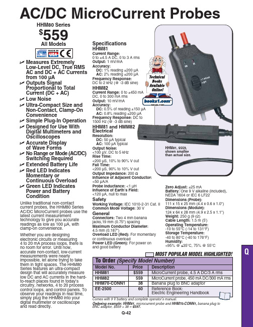
Q-42ߜ Measures Extremely Low-Level DC, True RMS AC and DC + AC Currents from 100 µA ߜOutputs SignalProportional to Total Current (DC + AC)ߜ Low NoiseߜUltra-Compact Size and Non-Contact, Clamp-On Convenienceߜ Simple Plug-In Operation ߜ Designed for Use With Digital Multimeters and Oscilloscopes ߜ Accurate Display of Wave FormsߜNo Range or Mode (AC/DC)Switching Required ߜ Extended Battery Life ߜ Red LED Indicates Momentary orContinuous Overload ߜGreen LED Indicates Power and Battery ConditionUnlike traditional non-contactcurrent probes, the HHM80 Series AC/DC MicroCurrent probes use the latest current measurement technology to give you accurate readings as low as 100 µA, with clamp-on convenience.Whether you are designing electronic circuits or measuring 4 to 20 mA process loops, there is no room for error. Until now,accurate non-contact, low-current measurements were nearlyimpossible, let alone trying to take them in tight spaces. The HHM80Series features an ultra-compact design that will accurately measure low DC and AC currents in the hard-to-reach places found in today’s circuitry, networks, 4 to 20 process control loops, and control panels. To observe your readings in real time,simply plug the HHM80 into your digital multimeter or oscilloscope and read directly.SpecificationsHHM81Current Range:0 to ±4.5 A DC, 0 to 3 A rms Output:1 mV/mA Accuracy:DC: 1% reading ±200 µA AC: 2% reading ±200 µA Frequency Response:DC to 2 kHz (@ -3 dB sine)HHM82Current Range:0 to ±450 mA DC, 0 to 300 mA rms Output:10 mV/mA Accuracy:DC:AC:0.8% reading ±200 µA Frequency Response:1500 Hz (@ -3 dB sine)HHM81 and HMM82 ElectricalResolution:DC: 50 µA typical AC:100 µA typical Output Noise:<100 µV, DC to 5 kHz Rise Time:<200 µS, 10% to 90% V out Fall Time:<200 µS, 90% to 10% V out Output Impedance:200 Ω<50 µA/AProbe Inductance:<1 µH Influence of Earth’s Field:<120 µA, null to maxSafetyWorking Voltage:IEC 1010-2-31 Cat. II Common Mode Voltage:30 VGeneralConnectors:Two 4 mm banana jacks,19 mm (0.75") spacingMaximum Conductor Diameter:4.5 mm (0.187")Overload LED (Red):For momentary or continuous overloadPower LED (Green):For power on and good batteryOrdering example:HHM81,microcurrent probe and HHM70-CONN1,banana plug to BNC adaptor, $559 + 38 = $597.HHM80 Series $559All ModelsHHM81, $559,shown smaller than actual size.AC/DC MicroCurrent Probes Zero Adjust:±25 mABattery:One 9 V alkaline (included), NEDA 1604 or IEC 6 LF22Dimensions (Probe):111 x 15 x 25 mm (4.4 x 0.6 x 1.0")Dimensions (Module):124 x 64 x 28 mm (4.9 x 2.5 x 1.1")Weight:250 g (9 oz)Cable Length:1.5 m (5')Operating Temperature:-10 to 55°C (-14 to 131°F)Storage Temperature:-40 to 80°C (-40 to 176°F)Humidity:<95% @ ≤35°C, 75% @ 55°CCANADA www.omega.ca Laval(Quebec) 1-800-TC-OMEGA UNITED KINGDOM www. Manchester, England0800-488-488GERMANY www.omega.deDeckenpfronn, Germany************FRANCE www.omega.frGuyancourt, France088-466-342BENELUX www.omega.nl Amstelveen, NL 0800-099-33-44UNITED STATES 1-800-TC-OMEGA Stamford, CT.CZECH REPUBLIC www.omegaeng.cz Karviná, Czech Republic596-311-899TemperatureCalibrators, Connectors, General Test and MeasurementInstruments, Glass Bulb Thermometers, Handheld Instruments for Temperature Measurement, Ice Point References,Indicating Labels, Crayons, Cements and Lacquers, Infrared Temperature Measurement Instruments, Recorders Relative Humidity Measurement Instruments, RTD Probes, Elements and Assemblies, Temperature & Process Meters, Timers and Counters, Temperature and Process Controllers and Power Switching Devices, Thermistor Elements, Probes andAssemblies,Thermocouples Thermowells and Head and Well Assemblies, Transmitters, WirePressure, Strain and ForceDisplacement Transducers, Dynamic Measurement Force Sensors, Instrumentation for Pressure and Strain Measurements, Load Cells, Pressure Gauges, PressureReference Section, Pressure Switches, Pressure Transducers, Proximity Transducers, Regulators,Strain Gages, Torque Transducers, ValvespH and ConductivityConductivity Instrumentation, Dissolved OxygenInstrumentation, Environmental Instrumentation, pH Electrodes and Instruments, Water and Soil Analysis InstrumentationHeatersBand Heaters, Cartridge Heaters, Circulation Heaters, Comfort Heaters, Controllers, Meters and SwitchingDevices, Flexible Heaters, General Test and Measurement Instruments, Heater Hook-up Wire, Heating Cable Systems, Immersion Heaters, Process Air and Duct, Heaters, Radiant Heaters, Strip Heaters, Tubular HeatersFlow and LevelAir Velocity Indicators, Doppler Flowmeters, LevelMeasurement, Magnetic Flowmeters, Mass Flowmeters,Pitot Tubes, Pumps, Rotameters, Turbine and Paddle Wheel Flowmeters, Ultrasonic Flowmeters, Valves, Variable Area Flowmeters, Vortex Shedding FlowmetersData AcquisitionAuto-Dialers and Alarm Monitoring Systems, Communication Products and Converters, Data Acquisition and Analysis Software, Data LoggersPlug-in Cards, Signal Conditioners, USB, RS232, RS485 and Parallel Port Data Acquisition Systems, Wireless Transmitters and Receivers。
MCCSEMI DMMT3906 三极管说明书

V(BR)EBO IBL ICEX
hFE(1) hFE(2) hFE(3) hFE(4) hFE(5)
-5
60 80 100 60 30
Collector-Emitter Saturation Voltage
VCE(sat)
Base-Emitter Saturation Voltage
Compliant. See Ordering Information)
DMMT3906
PNP Plastic Encapsulate
Transistors
Maximum Ratings @ 25°C Unless Otherwise Specified
• Operating Junction Temperature Range: -65℃ to +150℃ • Storage Temperature Range: -65℃ to +150℃ • Typical Thermal Resistance: 625℃/W Junction to Ambient
Common Emitter
-500μA
TA=25°C
-450μA
-400μA
-350μA -300μA
-250μA
-200μA -150μA
-100μA
IB=-50μA
-4
-8
-12
-16
-20
Collector-Emitter Voltage (V)
Fig. 3 - Collector-Emitter Saturation Voltage Characteristics
L
NOTE TYP.
0.65
力兴 CR1216 锂锰扣式电池 技术规格书说明书

版本/状态A/0锂/二氧化锰电池技 术 规 格 书电池型号:CR1216编制: 日期:审核: 日期:批准: 日期:客户确认: 日期:版本/状态A/0- 2 -1. 目的1.1 对武汉力兴(火炬)电源有限公司出品的锂电池的产品规格、测试方法进行规范,避免因测试条件、方法的不同引起偏差。
1.2 指导客户正确选择和使用我公司电池。
2. 产品类别和产品型号表13.产品基本特性表2序号 项目 特性1 标称容量*28 mAh (20±2℃时62K Ω负载电阻连续放电至2.0V )2 标称电压 3.0V3 工作温度范围 -20~+60℃4 最大脉冲电流5 mA 5 最大连续放电电流 2 mA6 结构及成分 二氧化锰正极、锂负极、有机电液、隔膜及不锈钢外壳等7重 量约0.6g* 标称容量:数值是在62K Ω负载、20±2℃、截止电压为2.0V 的条件下测得的。
(所测得的容量值会随着放电电流、温度以及截止电压的不同而变化)类别 型号 锂锰扣式电池CR1216版本/状态A/0- 3 -4. 外形示意图及尺寸(尺寸单位:mm )AФ12.5-0.3B1.6-0.25.外观电池的外观整洁,标志清晰,极性标识正确,表面无变形、锈迹、污点及泄漏。
6.特性 6.1电性能表3 序号 项目 测试条件常温一年内性能开路电压 室温 20±2 ℃ 3.0~3.5V 低温 -20±2 ℃ 3.0~3.5V 1高温 60±2 ℃ 3.0~3.5V工作电压 放电负载:62K Ω室温 20±2 ℃ ≥3.0V 低温 -20±2 ℃ ≥2.9V 2高温 60±2 ℃ ≥3.0V放电负载:62K Ω 工作寿命终止电压:2.0V室温 20±2 ℃ ≥550hrs 低温 -20±2 ℃ ≥330hrs 3高温60±2 ℃≥540hrs6.2性能检验6.2.1每项试验的样品数为6只。
Cummins Quiet Diesel QD 12000 商业发电机说明书
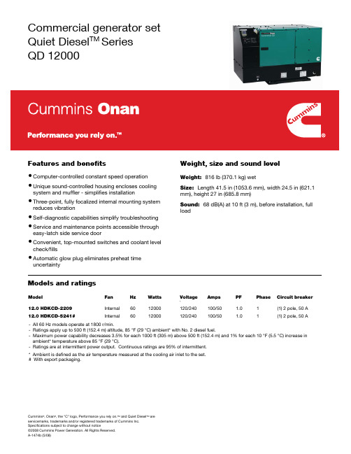
Commercial generator setQuiet Diesel TM SeriesQD 12000Features and benefits Weight, size and sound level•Computer-controlled constant speed operation •Unique sound-controlled housing encloses cooling system and muffler - simplifies installation •Three-point, fully focalized internal mounting system reduces vibration•Self-diagnostic capabilities simplify troubleshooting •Service and maintenance points accessible through easy-latch side service door •Convenient, top-mounted switches and coolant level check/fills•Automatic glow plug eliminates preheat time uncertainty Weight: 816 lb (370.1 kg) wetSize: Length 41.5 in (1053.6 mm), width 24.5 in (621.1 mm), height 27 in (685.8 mm)Sound: 68 dB(A) at 10 ft (3 m), before installation, full loadModels and ratingsModel Fan Hz Watts Voltage Amps PF PhaseCircuitbreaker`12.0 HDKCD-2209 Internal 60 12000 120/240 100/50 1.0 1 (1) 2 pole, 50 A12.0 HDKCD-5241#Internal 60 12000 120/240 100/50 1.0 1 (1) 2 pole, 50 A- All 60 Hz models operate at 1800 r/min.- Ratings apply up to 500 ft (152.4 m) altitude, 85 °F (29 °C) ambient* with No. 2 diesel fuel.- Maximum power capability decreases 3.5% for each 1000 ft (305 m) above 500 ft (152.4 m) and 1% for each 10 °F (5.5 °C) increase in ambient* temperature above 85 °F (29 °C).- Ratings are at intermittent power output. Continuous ratings are 95% of intermittent.* Ambient is defined as the air temperature measured at the cooling air inlet to the set.# With export packaging.Cummins®, Onan®, the "C" logo, Performance you rely on.TM and Quiet Diesel TM areStandard features Engine details•3 cylinder diesel engine•Brush type AC alternator•Digital voltage regulation•Bottom air inlet and outlet configuration•Integral enclosed muffler with stationary exhaust pipe connection point•USDA approved spark arresting muffler•Internal radiator•Sound attenuated housing•Intake silencer•Heavy duty air cleaner•Maintenance free electronic governor•Regulated-voltage 15 A battery charging•Hour meter•Waterproof connector for remote operation •Focalized mounting system with 3-point vibrationisolation•Over voltage, low oil pressure, over temp, overspeed, overload and AC alternator over temp safeties •Bulkhead type connections for fuel and battery •Terminal block connection for AC output•Electric fuel pump•Fuel filter•Full flow oil filter•Service and maintenance from side service door •Automatic timed glow plugs for quick easy start •Instant one touch stopypical fuel consumption Model: Kubota D1703-MDesign: 4-cycle, liquid-cooled diesel engine Cylinders: 3, inline verticalBore: 3.43 in (87.0 mm)Stroke: 3.64 in (92.4 mm)Displacement: 100.5 in3 (1647 cm3)Compression ratio: 23.0:1Lube oil capacity: 5.9 qt (5.6 L)Cooling system capacity: 6.6 qt (6.2 L)Power (max): At 1800 r/min: 27 hp (20.2 kW) (EPA Tier 2)Starting system: Remote, 12 VFuel injection pump: BoschCombustion chamber: IDIAlternator detailsDesign: Cummins Onan, brush type, drip-proof construction, 4 poleInsulation system: Class H per NEMA MG1-1.66 Exciter system: Electronic voltage regulator Bearings: Double sealed pre-lubricated ball bearing Cooling: Direct drive centrifugal blowerNo. 2 diesel fuel, Gal/hr (L/hr)No load Halfload Fullload12.0 HDKCD 0.11 (0.4) 0.48 (1.82) 1.20 (4.54)Generator set performanceFrequency regulation No load/Full load +/-0.1% Frequency variation Constant load +/- 0.6% Voltage regulation No load/Full load +/-2% Voltage variation Constant load +/- 0.5%Cummins®, Onan®, the "C" logo, Performance you rely on.TM and Quiet Diesel TM areBasic dimensionsDimensions: mm (in)Note: This outline drawing is provided for general reference only and is not intended for design or installation. For more information see Operation and Installation manuals or obtain drawing 500-4040 and wiring diagram from your distributor/dealer.Options and accessories•Exhaust elbow, 90° (P/N 155-3194)•Exhaust adapter, 3-inch (P/N 155-2610), 7-inch (P/N 155-2424)•Remote control pigtail (P/N 300-4947)•Remote control harness pigtail at panel (P/N 338-3573)•Remote control panel, switch only (P/N 300-4942) •Remote control panel, switch and hour meter (P/N 300-4943)•Remote control panel, switch and DC voltmeter (P/N 300-4944)•Remote harness (for use with remote panels), 10 ft (P/N 338-3490-01), 30 ft (P/N 338-3490-02)Cummins®, Onan®, the "C" logo, Performance you rely on.TM and Quiet Diesel TM areCummins ®, Onan ®, the "C" logo, Performance you rely on.TM and Quiet Diesel TM are Standards and testingAfter sale support- Tested at extremes of temperature -20 °F (-29 °C) to 120 °F (49 °C) for starting and operation - Tested with commercial loads - Tested in high humidity conditions- Tested in salt spray conditions - no direct spray allowed- Tested in heavy air borne dust conditions - Field test program- This product meets U.S. EPA Tier IV- This generator set was designed and manufactured in facilities certified to ISO 9001- CSA Certified for CSA C22.2 std 100 and std 14Warranty policyThe Cummins Onan limited warranty covers virtually everything except routine maintenance for the first two years that you own your generator set, or the first 2,000 hours of operation, whichever comes first. In addition, it includes a free 90-day adjustment policy, which provides that Cummins Inc. will make minor adjustments to your new generator set during the first three months you own it - free of charge!Largest distributor/dealer support networkCummins Onan generator sets are supported by the largest and best trained worldwide certifieddistributor/dealer network in the industry. This network of knowledgeable Cummins Onan distributor/dealers will help you select and install the right generator set and accessories to meet the requirements of your specific application. This same network offers a completeselection of commonly used generator set maintenance parts, accessories and products plus manuals and specification sheets. Plus, they can answer your questions regarding proper operation, maintenance schedules and more.Manuals: Operation and installation manuals ship with the generator set. To obtain additional copies or other manuals for this model, see your Cummins Onan distributor/dealer and request the following manual numbers: Operation (981-0173), Installation (981-0640), Parts (981-0277), Service (981-0540).To easily locate the nearest Cummins Onandistributor/dealer in your area, or for more information, contact us at 1-800-888-6626 (or 763-574-5000), or visit .Contact your distributor/dealer for more informationCummins Power Generation 1400 73rd Ave. NEMinneapolis, MN 55432 USA Phone 1 763 574 5000 Toll-free 1 800 888 6626 Fax 1 763 574 5298Email /contact Back feed to a utility system can cause electrocution and/or property damage. Do not connect to any building electrical except through an approved device or after building main breaker is open.WARNING:!Do not use this generator set on a boat. Such use may violate U.S. Coast Guard regulations, and can result in severe personal injury or death from fire, explosion, electrocution, or carbonmonoxide poisoning.WARNING:!。
SENTRON ACB 3WL1216-3BB32-4AS2-Z 三极电流保护器说明书
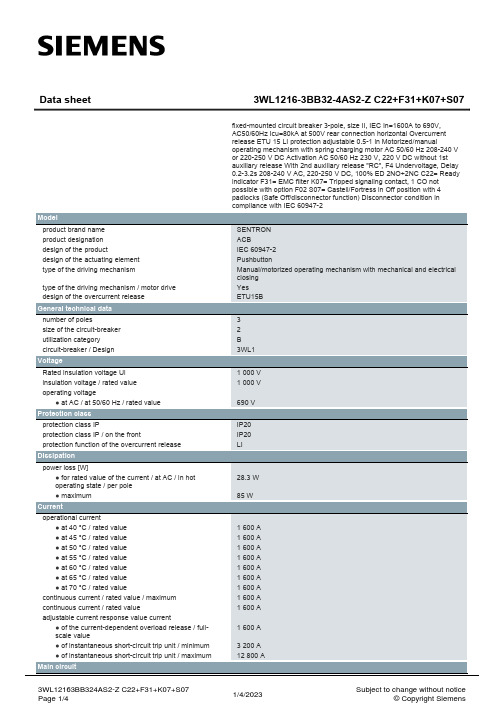
fixed-mounted circuit breaker 3-pole, size II, IEC In=1600A to 690V, AC50/60Hz Icu=80kA at 500V rear connection horizontal Overcurrent release ETU 15 LI protection adjustable 0.5-1 in Motorized/manual operating mechanism with spring charging motor AC 50/60 Hz 208-240 V or 220-250 V DC Activation AC 50/60 Hz 230 V, 220 V DC without 1st auxiliary release With 2nd auxiliary release "RC", F4 Undervoltage, Delay 0.2-3.2s 208-240 V AC, 220-250 V DC, 100% ED 2NO+2NC C22= Ready indicator F31= EMC filter K07= Tripped signaling contact, 1 CO not possible with option F02 S07= Castell/Fortress in Off position with 4 padlocks (Safe Off/disconnector function) Disconnector condition in compliance with IEC 609nditions
- 1、下载文档前请自行甄别文档内容的完整性,平台不提供额外的编辑、内容补充、找答案等附加服务。
- 2、"仅部分预览"的文档,不可在线预览部分如存在完整性等问题,可反馈申请退款(可完整预览的文档不适用该条件!)。
- 3、如文档侵犯您的权益,请联系客服反馈,我们会尽快为您处理(人工客服工作时间:9:00-18:30)。
仕 様 書形 名RCH1216B1.外形* 端子の寸法は、はんだつらら除く。
1-2.捺印表示例頭部直捺印捺印位置不定 2.コイル仕様 2-1.端子接続図(裏面図)(10μH~47μH) (56μH~2.2mH)* 10μH~47μHは、端子番号①と④、②と③を接続して御使用ください。
* 10μH~47μHは、端子②-③間又は①-④間の半田ブリッジが可とする。
①②③④①②③ compliance Cd:Max.0.01wt%others:Max.0.1wt%RoHS1仕 様 書形 名RCH1216B2-2.電気的特性直流重畳 許容電流 (A) ※3No. 品 名表示 インダクタンス[以内]※1D.C.R. (Ω) [以下] (at 20℃)※2 at 20℃at 100℃ 温度上昇許容電流 (A) ※4 スミダコード01 RCH1216BNP-1ØØM 100M 10μH ±20%24m(19m) 9.00 8.00 5.00 -000102 RCH1216BNP-12ØM 120M 12μH ±20%26m(21m) 7.80 7.00 4.60 -000203 RCH1216BNP-15ØM 150M 15μH ±20%29m(23m) 7.20 6.20 4.40 -000304 RCH1216BNP-18ØM 180M 18μH ±20%33m(26m) 6.75 5.80 4.20 -000405 RCH1216BNP-22ØM 220M 22μH ±20%37m(29m) 6.00 5.30 4.00 -000506 RCH1216BNP-27ØM 270M 27μH ±20%41m(32m) 5.50 4.80 3.80 -000607 RCH1216BNP-33ØM 330M 33μH ±20%46m(36m) 5.00 4.50 3.60 -000708 RCH1216BNP-39ØM 390M 39μH ±20%49m(39m) 4.70 4.10 3.30 -000809 RCH1216BNP-47ØM 470M 47μH ±20%56m(44m) 4.30 3.80 3.20 -000910 RCH1216BNP-56ØK 560K 56μH ±10%87m(69m) 4.10 3.70 2.70 -001011 RCH1216BNP-68ØK 680K 68μH ±10%98m(78m) 3.80 3.30 2.40 -001112 RCH1216BNP-82ØK 820K82μH ±10%107m(85m) 3.20 2.90 2.25 -001213 RCH1216BNP-1Ø1K 101K 100μH ±10%121m(96m) 3.00 2.70 2.15 -001314 RCH1216BNP-121K 121K 120μH ±10%134m(107m) 2.85 2.60 2.05 -001415 RCH1216BNP-151K 151K 150μH ±10%156m(124m) 2.55 2.35 1.90 -001516 RCH1216BNP-181K 181K 180μH ±10%206m(164m) 2.20 2.05 1.65 -001617 RCH1216BNP-221K 221K 220μH ±10%236m(188m) 2.00 1.85 1.55 -001718 RCH1216BNP-271K 271K 270μH ±10%0.32(0.25) 1.85 1.70 1.40 -001819 RCH1216BNP-331K 331K 330μH ±10%0.37(0.29) 1.65 1.53 1.30 -001920 RCH1216BNP-391K 391K 390μH ±10%0.48(0.38) 1.55 1.35 1.05 -002021 RCH1216BNP-471K 471K 470μH ±10%0.55(0.44) 1.45 1.25 1.00 -002122 RCH1216BNP-561K 561K 560μH ±10%0.62(0.49) 1.36 1.18 0.95 -002223 RCH1216BNP-681K 681K 680μH ±10%0.79(0.63) 1.20 1.06 0.82 -002324 RCH1216BNP-821K 821K 820μH ±10%0.88(0.70) 1.14 0.97 0.75 -002425 RCH1216BNP-1Ø2K 102K 1.0mH ±10% 1.13(0.90) 1.00 0.80 0.65 -002526 RCH1216BNP-122K 122K 1.2mH ±10% 1.25(1.00)0.89 0.76 0.61 -002627 RCH1216BNP-152K 152K 1.5mH ±10% 1.52(1.26)0.85 0.70 0.54 -002728 RCH1216BNP-182K 182K 1.8mH ±10% 1.93(1.60)0.76 0.63 0.46 -002829 RCH1216BNP-222K 222K2.2mH ±10%2.52(2.10)0.650.570.41-0029※1 測定周波数 インダクタンス at 1kHz ※2 ( )内は、標準値とする。
※3 直流重畳許容電流:直流重畳特性について、インダクタンスが初期値より10%となる電流値。
※4 温度上昇許容電流:通電時、コイルの温度上昇が△T=40℃になる電流値。
(Ta=20℃を基準とする。
)1.APPEARANCE1-1.DIMENSION* DIMENSION DOES NOT INCLUDE SOLDER USED ON COIL.DIRECTLY STAMPUNFIXED POSITION2.COIL SPECIFICATION2-1.CONNECTION (BOTTOM VIEW)(10μH~47μH) (56μH~2.2mH)※ TO BE CONNECTED BETWEEN #1 AND #4, #2 AND #3 (10μH~47μH) WHEN USING.※ IT IS NO MATTER FOR THE ELECTRIC CHARACTERISTICS IF TERMINAL 1 IS CONNECTED TO TERMINAL 4, TERMINAL 2 IS CONNECTED TO TERMINAL 3 WITH SOLDER. (ON THE BOTTOM OF DRUM CORE) (10μH~47μH)①②③④①②③④compliance Cd:Max.0.01wt%others:Max.0.1wt%RoHS12-2.ELECTRICAL CHARACTERISTICSDC SUPERPOSITIONPERMISSION CURRENT(A)※3NO. PART NO. STAMPINDUCTANCE[WITHIN]※1D.C.R.[MAX.](Ω)at 20℃※2 at 20℃at 100℃TEMPERATURERISE CURRENT(A)※4SUMIDACODE01 RCH1216BNP-1ØØM 100M 10μH ±20% 24m(19m) 9.00 8.00 5.00 -000102 RCH1216BNP-12ØM 120M 12μH ±20% 26m(21m) 7.80 7.00 4.60 -000203 RCH1216BNP-15ØM 150M 15μH ±20% 29m(23m) 7.20 6.20 4.40 -000304 RCH1216BNP-18ØM 180M 18μH ±20% 33m(26m) 6.75 5.80 4.20 -000405 RCH1216BNP-22ØM 220M 22μH ±20% 37m(29m) 6.00 5.30 4.00 -000506 RCH1216BNP-27ØM 270M 27μH ±20% 41m(32m) 5.50 4.80 3.80 -000607 RCH1216BNP-33ØM 330M 33μH ±20% 46m(36m) 5.00 4.50 3.60 -000708 RCH1216BNP-39ØM 390M 39μH ±20% 49m(39m) 4.70 4.10 3.30 -000809 RCH1216BNP-47ØM 470M 47μH ±20% 56m(44m) 4.30 3.80 3.20 -000910 RCH1216BNP-56ØK 560K 56μH ±10% 87m(69m) 4.10 3.70 2.70 -001011 RCH1216BNP-68ØK 680K 68μH ±10% 98m(78m) 3.80 3.30 2.40 -001112 RCH1216BNP-82ØK 820K 82μH ±10% 107m(85m) 3.20 2.90 2.25 -001213 RCH1216BNP-1Ø1K 101K 100μH ±10%121m(96m) 3.00 2.70 2.15 -001314 RCH1216BNP-121K 121K 120μH ±10%134m(107m) 2.85 2.60 2.05 -001415 RCH1216BNP-151K 151K 150μH ±10%156m(124m) 2.55 2.35 1.90 -001516 RCH1216BNP-181K 181K 180μH ±10%206m(164m) 2.20 2.05 1.65 -001617 RCH1216BNP-221K 221K 220μH±10% 236m(188m) 2.00 1.85 1.55 -001718 RCH1216BNP-271K 271K 270μH±10% 0.32(0.25) 1.85 1.70 1.40 -001819 RCH1216BNP-331K 331K 330μH±10% 0.37(0.29) 1.65 1.53 1.30 -001920 RCH1216BNP-391K 391K 390μH±10% 0.48(0.38) 1.55 1.35 1.05 -002021 RCH1216BNP-471K 471K 470μH±10% 0.55(0.44) 1.45 1.25 1.00 -002122 RCH1216BNP-561K 561K 560μH±10% 0.62(0.49) 1.36 1.18 0.95 -002223 RCH1216BNP-681K 681K 680μH±10% 0.79(0.63) 1.20 1.06 0.82 -002324 RCH1216BNP-821K 821K 820μH±10% 0.88(0.70) 1.14 0.97 0.75 -002425 RCH1216BNP-1Ø2K 102K 1.0mH ±10% 1.13(0.90) 1.00 0.80 0.65 -002526 RCH1216BNP-122K 122K 1.2mH ±10% 1.25(1.00)0.89 0.76 0.61 -002627 RCH1216BNP-152K 152K 1.5mH ±10% 1.52(1.26)0.85 0.70 0.54 -002728 RCH1216BNP-182K 182K 1.8mH ±10% 1.93(1.60)0.76 0.63 0.46 -002829 RCH1216BNP-222K 222K 2.2mH ±10% 2.52(2.10)0.65 0.57 0.41 -0029※1 MEASURING FREQUENCY at 1kHz※2 ( ) ARE TYPICAL VALUE.※3 DC SUPERPOSITION PERMISSION CURRENT:THIS INDICATES THE VALUE OF CURRENT WHEN THE INDUCTANCE IS 10% LOWER THAN ITS INITIAL VALUE AT D.C. SUPERPOSITION.※4 THE CURRENT WHEN COIL’S SELF TEMnERATURE RISE IS △T=40℃. (Ta=20℃)G。
