2SD1979T中文资料
2SD1710中文资料(Wing Shing)中文数据手册「EasyDatasheet - 矽搜」
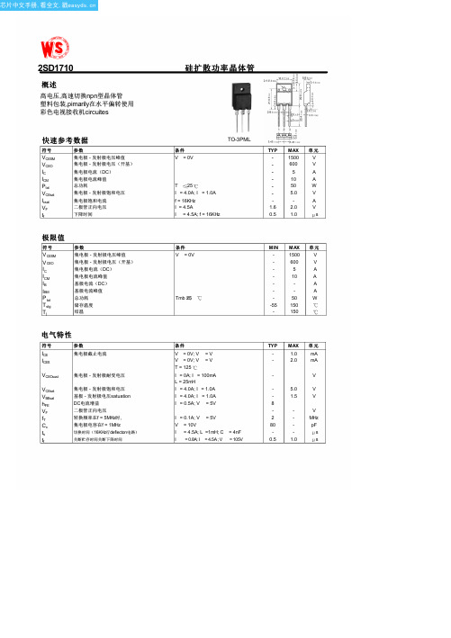
硅扩散功率晶体管
条件
V = 0V
TO-3PML
T 25 I = 4.0A; I = 1.0A f = 16KHz I = 4.5A I = 4.5A; f = 16KHz
TYP MAX 单元
-
1500
V
-
600
V
-
5
A
-
10
A
-
50
W
-
5.0
V
-
-
A
1.6
2.0
V
0.5
1.0
芯片中文手册,看全文,戳
2SD1710
概述
高电压,高速切换npn型晶体管 塑料包装,pimarily在水平偏转使用 彩色电视接收机circuites
快速参考数据
符号
VCESM VCEO IC ICM Ptot VCEsat Icsat VF tf
参数
集电极 - 发射极电压峰值 集电极 - 发射极电压(开基) 集电极电流(DC)
s
条件
V = 0V
Tmb 25
MIN MAX 单元
-
1500
V
-
600
V
-
5
A
-
10
A
-
-
A
-
-
A
-
50
W
-55 150
-
150
条件
V = 0V; V = V V = 0V; V = V T = 125 I = 0A; I = 100mA L = 25mH I = 4.0A; I = 1.0A I = 4.0A; I = 1.0A I = 0.5A; V = 5V
CBM97D79TQ产品手册说明书

产品特点●低功耗(全部工作条件下):1.0W@1GSPS、600mW@500MSPS●单载波WCDMA的ACLR:80dBc@80MHz中频●可调模拟输出:8.7mA-31.7mA(R L=25Ω-50Ω)●新颖的2×、4×、8×插值器/粗调、复数调制器可以将载波放在DAC带宽中的任何位置●辅助DAC可控制外部VGA及失调●多芯片同步接口●高性能、低噪声锁相环时钟倍频器●数字反sinc滤波器●100引脚TQFP100封装应用范围●无线基础设施:W-CDMA、GSM、CDMA2000、TD-SCDMA、WiMax、LTE●数字高/低中频合成●内部数字上变频功能●发射分集●宽带通信:LMDS、MMDS、点对点通信产品描述CBM97D79TQ是一款双通道、16位、高动态范围数模转换器。
该转换器可提供高达1GSPS采样速率;并可以产生最高达奈奎斯特频率的多载波。
本产品具有针对直接变频传输应用进行优化的特性,这些特性包括:数字实/复调制以及增益与失调补偿等功能。
产品中的DAC内核输出级经过优化,可以与主流的模拟正交调制器无缝接口,如:ADI公司的ADL537X FMOD系列调制器。
三线式接口允许对许多内部参数进行编程和回读。
DAC内核满量程输出电流可以在10mA至30mA范围内进行编程调节。
本产品采用先进的0.18μm CMOS工艺制造,采用1.8V/3.3V电源供电,总功耗为1.0W。
CBM97D79TQ从功能上可以划分为数字滤波器单元、DAC内核单元、时钟(包含内部锁相环)单元、辅助DAC、多芯片同步单元等。
数字部分对输入的信号进行数字内插和数字域实调制、复调制功能;DAC内核对数字信号进行数字到模拟的转换;SPI对整个芯片进行配置;时钟单元为整个电路提供高质量的时钟、四个辅助DAC用于通道增益和失调校正、多芯片同步单元负责多个芯片间的同步功能。
CBM97D79TQ功能框图如图1所示:图1CBM97D79TQ功能框图引脚排列图(俯视图)图2引脚排列图引脚简述引脚编号引脚名称描述引脚编号引脚名称描述1CVDD18 1.8V时钟电源32DGND数字地2CVDD18 1.8V时钟电源33DVDD18 1.8V数字电源3CGND时钟地34P1D2端口1数据输入D2 4CGND时钟地35P1D1端口1数据输入D1 5REFCLK+差分时钟输入36P1D0端口1数据输入D0(LSB) 6REFCLK−差分时钟输入37DATACLK数据时钟输出7CGND时钟地38DVDD33 3.3V数字电源8CGND时钟地39TXENABLE/IQSELECT发送使能。
MAX1978中文数据手册

用于Peltier模块的集成温度控制器概论MAX1978 / MAX1979是用于Peltier热电冷却器(TEC)模块的最小, 最安全, 最精确完整的单芯片温度控制器。
片上功率FET和热控制环路电路可最大限度地减少外部元件, 同时保持高效率。
可选择的500kHz / 1MHz开关频率和独特的纹波消除方案可优化元件尺寸和效率, 同时降低噪声。
内部MOSFET的开关速度经过优化, 可降低噪声和EMI。
超低漂移斩波放大器可保持±0.001°C的温度稳定性。
直接控制输出电流而不是电压, 以消除电流浪涌。
独立的加热和冷却电流和电压限制提供最高水平的TEC保护。
MAX1978采用单电源供电, 通过在两个同步降压调节器的输出之间偏置TEC, 提供双极性±3A输出。
真正的双极性操作控制温度, 在低负载电流下没有“死区”或其他非线性。
当设定点非常接近自然操作点时, 控制系统不会捕获, 其中仅需要少量的加热或冷却。
模拟控制信号精确设置TEC 电流。
MAX1979提供高达6A的单极性输出。
提供斩波稳定的仪表放大器和高精度积分放大器, 以创建比例积分(PI)或比例积分微分(PID)控制器。
仪表放大器可以连接外部NTC或PTC热敏电阻, 热电偶或半导体温度传感器。
提供模拟输出以监控TEC温度和电流。
此外, 单独的过热和欠温输出表明当TEC温度超出范围时。
片上电压基准为热敏电阻桥提供偏置。
MAX1978 / MAX1979采用薄型48引脚薄型QFN-EP 封装, 工作在-40°C至+ 85°C温度范围。
采用外露金属焊盘的耐热增强型QFN-EP封装可最大限度地降低工作结温。
评估套件可用于加速设计。
应用光纤激光模块典型工作电路出现在数据手册的最后。
WDM, DWDM激光二极管温度控制光纤网络设备EDFA光放大器电信光纤接口ATE特征♦尺寸最小, 最安全, 最精确完整的单芯片控制器♦片上功率MOSFET-无外部FET♦电路占用面积<0.93in2♦回路高度<3mm♦温度稳定性为0.001°C♦集成精密积分器和斩波稳定运算放大器♦精确, 独立的加热和冷却电流限制♦通过直接控制TEC电流消除浪涌♦可调节差分TEC电压限制♦低纹波和低噪声设计♦TEC电流监视器♦温度监控器♦过温和欠温警报♦双极性±3A输出电流(MAX1978)♦单极性+ 6A输出电流(MAX1979)订购信息* EP =裸焊盘。
MAX1978ETM+;MAX1979ETM+;MAX1978ETM+T;MAX1979ETM+T;中文规格书,Datasheet资料

General DescriptionThe MAX1978/MAX1979 are the smallest, safest, most accurate complete single-chip temperature controllers for Peltier thermoelectric cooler (TEC) modules. On-chip power FETs and thermal control-loop circuitry minimize external components while maintaining high efficiency. Selectable 500kHz/1MHz switching frequency and a unique ripple-can-cellation scheme optimize component size and efficiency while reducing noise. Switching speeds of internal MOSFETs are optimized to reduce noise and EMI. An ultra-low-drift chopper amplifier maintains ±0.001°C temperature stability. Output current, rather than voltage, is directly con-trolled to eliminate current surges. Individual heating and cooling current and voltage limits provide the highest level of TEC protection.The MAX1978 operates from a single supply and provides bipolar ±3A output by biasing the TEC between the outputs of two synchronous buck regulators. True bipolar operation controls temperature without “dead zones” or other nonlin-earities at low load currents. The control system does not hunt when the set point is very close to the natural operating point, where only a small amount of heating or cooling is needed. An analog control signal precisely sets the TEC current. The MAX1979 provides unipolar output up to 6A.A chopper-stabilized instrumentation amplifier and a high-precision integrator amplifier are supplied to create a pro-portional-integral (PI) or proportional-integral-derivative (PID)controller. The instrumentation amplifier can interface to an external NTC or PTC thermistor, thermocouple, or semicon-ductor temperature sensor. Analog outputs are provided to monitor TEC temperature and current. In addition, separate overtemperature and undertemperature outputs indicate when the TEC temperature is out of range. An on-chip volt-age reference provides bias for a thermistor bridge.The MAX1978/MAX1979 are available in a low-profile 48-lead thin QFN-EP package and is specified over the -40°C to +85°C temperature range. The thermally enhanced QFN-EP package with exposed metal pad minimizes operating junction temperature. An evaluation kit is available to speed designs.ApplicationsFiber Optic Laser ModulesWDM, DWDM Laser-Diode Temperature Control Fiber Optic Network Equipment EDFA Optical Amplifiers Telecom Fiber Interfaces ATEFeatureso Smallest, Safest, Most Accurate Complete Single-Chip Controllero On-Chip Power MOSFETS—No External FETs o Circuit Footprint < 0.93in 2o Circuit Height < 3mmo Temperature Stability to 0.001°Co Integrated Precision Integrator and Chopper Stabilized Op Ampso Accurate, Independent Heating and Cooling Current Limitso Eliminates Surges By Directly Controlling TEC Currento Adjustable Differential TEC Voltage Limit o Low-Ripple and Low-Noise Design o TEC Current Monitor o Temperature Monitoro Over- and Undertemperature Alarm o Bipolar ±3A Output Current (MAX1978)o Unipolar +6A Output Current (MAX1979)MAX1978/MAX1979Integrated TemperatureControllers for Peltier Modules________________________________________________________________Maxim Integrated Products1Ordering InformationPin Configuration19-2490; Rev 3; 3/10For pricing, delivery, and ordering information,please contact Maxim Direct at 1-888-629-4642,or visit Maxim’s website at .Typical Operating Circuit appears at end of data sheet.+Denotes a lead(Pb)-free/RoHS-compliant package.M A X 1978/M A X 1979Integrated TemperatureControllers for Peltier ModulesABSOLUTE MAXIMUM RATINGSELECTRICAL CHARACTERISTICS(V = PV 1 = PV 2 = V = 5V, FREQ = GND, CTLI = FB+ = FB- = MAXV = MAXIP = MAXIN = REF, T = 0°C to +85°C ,Stresses beyond those listed under “Absolute Maximum Ratings” may cause permanent damage to the device. These are stress ratings only, and functional operation of the device at these or any other conditions beyond those indicated in the operational sections of the specifications is not implied. Exposure to absolute maximum rating conditions for extended periods may affect device reliability.V DD to GND..............................................................-0.3V to +6V SHDN , MAXV, MAXIP, MAXIN,CTLI, OT , UT to GND............................................-0.3V to +6V FREQ, COMP, OS1, OS2, CS, REF, ITEC, AIN+, AIN-, AOUT, INT-, INTOUT, BFB+, BFB-, FB+, FB-,DIFOUT to GND......................................-0.3V to (V DD + 0.3V)PV DD 1, PV DD 2 to V DD ...........................................-0.3V to +0.3V PV DD 1, PV DD 2 to GND...............................-0.3V to (V DD + 0.3V)PGND1, PGND2 to GND.......................................-0.3V to +0.3V COMP, REF, ITEC, OT , UT , INTOUT, DIFOUT,BFB-, BFB+, AOUT Short to GND .............................IndefinitePeak LX Current (MAX1978) (Note 1).................................±4.5A Peak LX Current (MAX1979) (Note 1)....................................+9A Continuous Power Dissipation (T A = +70°C) 48-Lead Thin QFN-EP(derate 26.3mW/°C above +70°C) (Note 2).................2.105W Operating Temperature RangesMAX1978ETM..................................................-40°C to +85°C MAX1979ETM..................................................-40°C to +85°C Maximum Junction Temperature.....................................+150°C Storage Temperature Range.............................-65°C to +150°C Lead Temperature (soldering, 10s).................................+300°CNote 1:LX has internal clamp diodes to PGND and PV DD . Applications that forward bias these diodes should not exceed the IC’spackage power dissipation limits.Note 2:Solder underside metal slug to PCB ground plane.MAX1978/MAX1979Integrated TemperatureControllers for Peltier ModulesELECTRICAL CHARACTERISTICS (continued)(V = PV 1 = PV 2 = V SHDN = 5V, FREQ = GND, CTLI = FB+ = FB- = MAXV = MAXIP = MAXIN = REF, T = 0°C to +85°C ,M A X 1978/M A X 1979Integrated TemperatureControllers for Peltier Modules 4_______________________________________________________________________________________ELECTRICAL CHARACTERISTICS (continued)(V DD = PV DD 1 = PV DD 2 = V SHDN = 5V, FREQ = GND, CTLI = FB+ = FB- = MAXV = MAXIP = MAXIN = REF, T A = 0°C to +85°C ,MAX1978/MAX1979Integrated TemperatureControllers for Peltier Modules_______________________________________________________________________________________5ELECTRICAL CHARACTERISTICS(V DD = PV DD 1 = PV DD 2 = V SHDN = 5V, FREQ = GND, CTLI = FB+ = FB- = MAXV = MAXIP = MAXIN = REF, T A = -40°C to +85°C ,unless otherwise noted.) (Note 5)Note 4:CTLI gain is defined as:Note 5:Specifications to -40°C are guaranteed by design, not production tested.M A X 1978/M A X 1979Integrated TemperatureControllers for Peltier Modules 6_______________________________________________________________________________________ELECTRICAL CHARACTERISTICS (continued)MAX1978/MAX1979Integrated TemperatureControllers for Peltier Modules_______________________________________________________________________________________7EFFICIENCY vs. TEC CURRENTV DD = 5VTEC CURRENT (A)E F F I C I E N C Y (%)2.01.51.00.5102030405060708090002.5EFFICIENCY vs. TEC CURRENTV DD= 3.3VTEC CURRENT (A)2.01.50.51.01020304050607080002.5E F F I C I EN C Y (%)OUTPUT-VOLTAGE RIPPLE WAVEFORMSM A X 1978 t o c 03400ns/divV OS2100mV/divAC-COUPLEDVOS1100mV/div AC-COUPLEDV OS1 - V OS150mV/divINPUT SUPPLY RIPPLEM A X 1978 t o c 04200ns/div V DD20mV/div AC-COUPLEDTEC CURRENT vs. CTLI VOLTAGE20ms/div V CTLI 1V/div I TEC 2A/divZERO-CROSSING TEC CURRENTM A X 1978 t o c 061ms/divV CTLI 200mV/divI TEC 500mA/div1.5V0AV ITEC vs. TEC CURRENTM A X 1978 t o c 07TEC CURRENT (A)V I T E C (V )21-1-20.51.01.52.02.53.00-33TEC CURRENT vs. TEMPERATURETEMPERATURE (°C)I T E C (A )80604020-200.9951.0001.0051.0100.990-40SWITCHING FREQUENCY vs. TEMPERATURES W I T C H I N G F R E Q U E N C Y (k H z )494496498500502504506508492TEMPERATURE (°C)80604020-20-40Typical Operating Characteristics(V DD = 5V, V CTLI = 1V, V FREQ = GND, RTEC = 1Ω, circuit of Figure 1, T A = +25°C, unless otherwise noted.)M A X 1978/M A X 1979Integrated TemperatureControllers for Peltier Modules 8_______________________________________________________________________________________SWITCHING FREQUENCY CHANGEvs. INPUT SUPPLYM A X 1978 t o c 10V DD (V)S W I T C H I N G F R E Q U E N C Y C H A N G E (k H z )5.04.54.03.5-30-25-20-15-10-50510-353.05.5REFERENCE VOLTAGE CHANGEvs. INPUT SUPPLYR E F E R E N C E V O L T A G E C H A N G E (m V )-2.5-2.0-1.5-1.0-0.500.51.0-3.0M A X 197 t o c 11V DD (V) 5.04.54.03.53.05.5REFERENCE VOLTAGE CHANGEvs. TEMPERATUREM A X 1978 t o c 12TEMPERATURE (°C)R E F E R E N C E V O L T A G E C H A N G E (m V )6040200-20-3-2-10123-4-4080REFERENCE LOAD REGULATIONREFERENCE LOAD CURRENT (mA)R E F E R E N C E V O L T A G EC H A N G E (m V )0.80.6-0.20.20.4-0.8-0.6-0.4-0.200.20.40.6-1.0-0.41.0ATO VOLTAGEvs. THERMISTOR TEMPERATURETHERMISTOR TEMPERATURE (°C)302010-10405060STARTUP AND SHUTDOWN WAVEFORMSM A X 1978 t o c 15100µs/divV SHDN 5V/divI TEC 500mA/divI DD200mA/divCTLI STEP RESPONSEM A X 1978 t o c 161ms/div 1.5V0AV CTLI 1V/div I TEC1A/divINPUT SUPPLY STEP RESPONSEM A X 1978 t o c 171A0VV DD 2V/divI TEC 20mA/div10ms/div THERMAL STABILITY,COOLING MODE4s/divTEMPERATURE 0.001°C/div Typical Operating Characteristics (continued)(V DD = 5V, V CTLI = 1V, V FREQ = GND, RTEC = 1Ω, circuit of Figure 1, T A = +25°C, unless otherwise noted.)MAX1978/MAX1979Integrated TemperatureControllers for Peltier ModulesTHERMAL STABILITY,ROOM TEMPERATURE4s/div TEMPERATURE 0.001°C/div I TEC = +25°C T A = +25°C THERMAL STABILITY,HEATING MODE4s/div TEMPERATURE 0.001°C/divT TEC = +25°C T A = +5°CTEMPERATURE ERROR vs. AMBIENT TEMPERATUREM A X 1978 t o c 21AMBIENT TEMPERATURE (°C)T E M P E R A T U R E E R R O R (°C )304010200-10-0.02-0.0100.010.020.03-0.03-2050Typical Operating Characteristics (continued)(V DD = 5V, V CTLI = 1V, V FREQ = GND, RTEC = 1Ω, circuit of Figure 1, T A = +25°C, unless otherwise noted.)M A X 1978/M A X 1979Integrated TemperatureControllers for Peltier Modules 10______________________________________________________________________________________分销商库存信息:MAXIMMAX1978ETM+MAX1979ETM+MAX1978ETM+T MAX1979ETM+T。
AOCV27TChinese

电视机的连接和准备
在墙上安装电视
本电视符合墙上安装的 VESA 标准,请参阅规格页了解壁挂尺寸。 需要挂墙时,为保障您及本机的安全,请使用原厂挂墙支架并由专业人员安装。 如果您要把电视机挂在墙上,所有连接线都必须先插入电视机的接口。电视机 与墙面必须至少保持 6 厘米的距离以确保所有接口都有足够的空间可以插入。 不论您在何处放置或悬挂电视机,都应确保空气可以通过通风槽进行自由流 通。 不要把电视机放在封闭的空间内。
安装底座
从纸箱中取出电视以及底座,利用附件盒中的螺丝将它们组装起来,具体如下 图所示: 1. 将电视机正面朝下放在桌面上的软布或软垫上。拧紧底座上的螺丝,
将脚座和支架固定在一起。 2. 将脚座插入电视底部的孔中。
拆卸底座
请使用螺丝刀头插入支架固定孔,用力向下按压,同时拔出底座。
电视机的连接和准备
将电视放在稳固的平面上
20. 电力线路 – 室外天线应远离电力线路。 21. 室外天线接地 – 如果外部天线连接到接收器,确定该天线系统已接地,可以提
供保护,能防止电涌和静电聚集。 National Electric Code 的 810 节, ANSI/NFPA No. 70-1984 提供了以下方面 的信息:线网正确接地,天线引入线到天线放电装置的支撑结构接地,接地接头 的大小,天线充电装置的位置,接地电极的连接,以及接地电极的要求。请参阅 下图。
中国大陆rohs法规标示要求根据中国大陆电子信息产品污染控制管理办法也称为中国大陆rohs以下部分列出了本产品中可能包含的有毒有害物质或元素的名称和含量本表适用之产品显示器液晶及crt平板电视液晶及等离子监视器有毒有害物质或元素有毒有害物质或元素部件名称铅pb汞hg镉cd多溴联苯pbbpbde外壳
L297,L298中文资料介绍
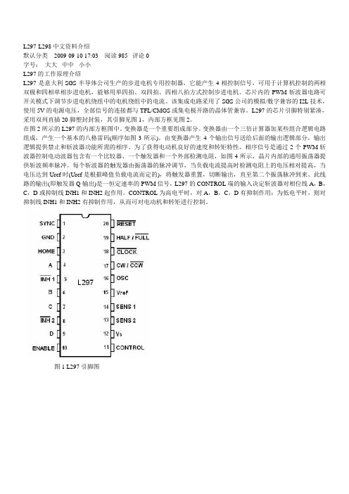
L297-L298中文资料介绍默认分类 2009-09-10 17:03 阅读985 评论0字号:大大中中小小L297的工作原理介绍L297是意大利SGS半导体公司生产的步进电机专用控制器,它能产生4相控制信号,可用于计算机控制的两相双极和四相单相步进电机,能够用单四拍、双四拍、四相八拍方式控制步进电机。
芯片内的PWM斩波器电路可开关模式下调节步进电机绕组中的电机绕组中的电流。
该集成电路采用了SGS公司的模拟/数字兼容的I2L技术,使用5V的电源电压,全部信号的连接都与TFL/CMOS或集电极开路的晶体管兼容。
L297的芯片引脚特别紧凑,采用双列直插20脚塑封封装,其引脚见图1,内部方框见图2。
在图2所示的L297的内部方框图中。
变换器是一个重要组成部分。
变换器由一个三倍计算器加某些组合逻辑电路组成,产生一个基本的八格雷码(顺序如图3所示)。
由变换器产生4个输出信号送给后面的输出逻辑部分,输出逻辑提供禁止和斩波器功能所需的相序。
为了获得电动机良好的速度和转矩特性,相序信号是通过2个PWM斩波器控制电动波器包含有一个比较器、一个触发器和一个外部检测电阻,如图4所示,晶片内部的通用振荡器提供斩波频率脉冲。
每个斩波器的触发器由振荡器的脉冲调节,当负载电流提高时检测电阻上的电压相对提高,当电压达到Uref时(Uref是根据峰值负载电流而定的),将触发器重置,切断输出,直至第二个振荡脉冲到来、此线路的输出(即触发器Q输出)是一恒定速率的PWM信号,L297的CONTROL端的输入决定斩波器对相位线A,B,C,D或抑制线INH1和INH2起作用。
CONTROL为高电平时,对A,B,C,D有抑制作用;为低电平时,则对抑制线INH1和INH2有抑制作用,从而可对电动机和转矩进行控制。
图1 L297引脚图图2 L297内部方框电路图图3 L297变换器换出的八步雷格码(顺时针旋转)图4 斩波器线路图5 多个L297同步工作连接图L297各引脚功能说明1脚(SYNG)——斩波器输出端。
MAX1979ETM资料

Features
♦ Smallest, Safest, Most Accurate Complete Single-Chip Controller On-Chip Power MOSFETS—No External FETs Circuit Footprint < 0.93in2 Circuit Height < 3mm Temperature Stability to 0.001°C Integrated Precision Integrator and Chopper Stabilized Op Amps ♦ Accurate, Independent Heating and Cooling Current Limits ♦ Eliminates Surges By Directly Controlling TEC Current ♦ Adjustable Differential TEC Voltage Limit ♦ Low-Ripple and Low-Noise Design ♦ TEC Current Monitor ♦ ♦ ♦ ♦ Temperature Monitor Over- and Undertemperature Alarm Bipolar ±3A Output Current (MAX1978) Unipolar +6A Output Current (MAX1979)
MAX1978/MAX1979
Ordering Information
PART MAX1978ETM TEMP RANGE PIN-PACKAGE -40°C to +85°C 48 Thin QFN-EP* PKG CODE T4877-6 T4877-6
MAX1979ETM -40°C to +85°C 48 Thin QFN-EP* *EP = Exposed paddle.
2SD2150中文资料
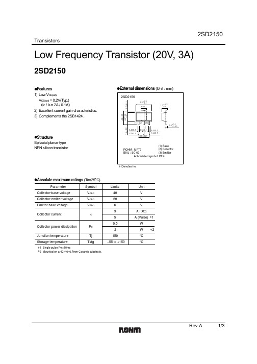
TransistorsRev.A 1/3Low Frequency Transistor (20V, 3A)2SD2150z Features 1) Low V CE(sat).V CE(sat) = 0.2V(Typ.) (I C / I B = 2A / 0.1A )2) Excellent current gain characteristics. 3) Complements the 2SB1424.z StructureEpitaxial planar type NPN silicon transistorz External dimensions (Unit : mm)Denotes h FEz Absolute maximum ratings (T a=25°C)ParameterV CBO V CEO V EBO I CP C Tj Tstg40V V V A (DC)W W°C °C2063 A (Pulse)50.52∗1∗2150−55 to +150Symbol Limits Unit ∗1 Single pulse Pw =10ms∗2 Mounted on a 40×40×0.7mm Ceramic substrate.Collector-base voltage Collector-emitter voltage Emitter-base voltage Collector currentCollector power dissipation Junction temperature Storage temperatureTransistorsRev.A 2/3z Electrical characteristics (T a=25°C)ParameterSymbol BV CBO BV CEO BV EBO I CBO I EBO h FE V CE(sat)f T CobMin.40206−−120−−−−−−−−−0.229025−−−0.10.15600.5−−V I C =50µA I C =1mA I E =50µA V CB =30V V EB =5VV CE =2V, I C =0.1AI C /I B =2A/0.1A V CE =2V, I E = −0.5A, f =100MHz V CE =10V, I E =0A, f =1MHzV VµA µA −V ∗MHz pFTyp.Max.Unit Conditions∗ Measured using pulse current.Collector-base breakdown voltage Collector-emitter breakdown voltage Emitter-base breakdown voltage Collector cutoff current Emitter cutoff currentDC current transfer ratio Collector-emitter saturation voltageTransition frequency Output capacitancez Packaging specifications and h FEPackage CodeT1001000Taping Basic ordering unit (pieces)RSh FE 2SD2150Typeh FE values are classified as follows :Item h FER 180 to 390S 270 to 560z Electrical characteristic curvesC O L L E C T O R C U R R E N T : I C (A )BASE TO EMITTER VOLTAGE : V BE (V)Fig.1 Grounded emitter propagationcharacteristicsC O L L E C T O R C U R R E N T : I C(A )COLLECTOR TO EMITTER VOLTAGE : V CE (V)Fig.2 Grounded emitter outputcharacteristics ( ) C O L L E C T O R C U R R E N T : I C (A )COLLECTOR TO EMITTER VOLTAGE : V CE (V)Fig.3 Grounded emitter outputcharacteristics ( )TransistorsRev.A 3/3D C C U R RE N T G A I N : hF ECOLLECTOR CURRENT : I C (A)Fig.4 DC current gain vs.collector currentC O L L E C T O R S A T U R A T I O N V O L T A G E : V C E (s a t ) (V )COLLECTOR CURRENT : I C (A)Fig.6 Collector-emittersaturation voltage vs.collector curren ( )C O L L E C T O R S A T U R A T I O N V O L T A G E : V C E (s a t ) (V )COLLECTOR CURRENT : I C (A)Fig.5 Collector-emittersaturation voltage vs. collector current ( )C O L L E C T O R O U T P U T C A P A C I T A N C E : C o b (p F )E M I T T E R I N P U T C A P A C I T A N C E : C i b (p F )COLLECTOR TO BASE VOLTAGE : V CB (V)EMITTER TO BASE VOLTAGE : V EB (V)Fig.9 Collector output capacitance vs.collector-base voltageEmitter input capacitance vs.emitter-base voltageC O L L E C T O R S A T U R A T I O N V O L T A G E : V C E (s a t ) (V )COLLECTOR CURRENT : I C (A)Fig.7 Collector-emittersaturation voltage vs.collector current ( )T R A N S I T I O N F R E Q U E N C Y : f T (M H z )EMITTER CURRENT : I E (mA)Fig.8 Gain bandwidth product vs.emitter currentAppendixAbout Export Control Order in JapanProducts described herein are the objects of controlled goods in Annex 1 (Item 16) of Export T rade ControlOrder in Japan.In case of export from Japan, please confirm if it applies to "objective" criteria or an "informed" (by MITI clause)on the basis of "catch all controls for Non-Proliferation of Weapons of Mass Destruction.Appendix1-Rev1.1。
2SD1782KT146R;2SD1782KT146Q;中文规格书,Datasheet资料

TransistorsRev.A 1/3Power Transistor (80V, 0.5A)2SD1782Kz Features 1) Low V CE(sat).V CE(sat) =0.2V(Typ.) (I C / I B =0.5 A / 50mA) 2) High V CEO, V CEO =80V3) Complements the 2SB1198K.z StructureEpitaxial planar type NPN silicon transistor z External dimensions (Unit : mm)0~0.12.8±0.21.60.3~0.61.10.8±0.10.150.42.9±0.21.9±0.20.950.95+0.2−0.1−0.1+0.2+0.1−0.06+0.1−0.05(2)(1)(3)(1) Emitter (2) Base (3) CollectorROHM : SMT3EIAJ : SC-59Abbreviated symbol : AJ ∗All terminals havesame dimensions∗ Denotes h FEz Absolute maximum ratings (T a=25°C)ParameterV CBO V CEO V EBO P C Tj Tstg80V V V A W°C °C8050.5I C 0.2150−55 to +150Symbol Limits Unit Collector-base voltage Collector-emitter voltage Emitter-base voltage Collector currentCollector power dissipation Junction temperature Storage temperatureTransistorsRev.A 2/3z Electrical characteristics (T a=25°C)ParameterSymbol BV CBO BV CEO BV EBO I CBO I EBO h FE V CE(sat)f T CobMin.80805−−120−−−−−−−−−0.21207.5−−−0.50.53900.5−−V I C =50µA I C =2mA I E =50µA V CB =50V V EB =4VV CE =3V, I C =100mAI C /I B =500mA/50mA V CE =10V, I E = −50mA, f =100MHz V CB =10V, I E =0A, f =1MHzV VµA µA −V MHz pFTyp.Max.Unit ConditionsCollector-base breakdown voltage Collector-emitter breakdown voltage Emitter-base breakdown voltage Collector cutoff current Emitter cutoff currentDC current transfer ratio Collector-emitter saturation voltage Output capacitanceTransition frequencyz Packaging specifications and h FEPackage CodeT1463000Taping Basic ordering unit (pieces)QRh FE 2SD1782KTypeh FE values are classified as follows :Item Q h FE120 to 270R 180 to 390z Electrical characteristic curvesC O L L E C T O R C U R R E N T : I C (m A )BASE TO EMITTER VOLTAGE : V BE (V)Fig.1 Grounded emitter propagationcharacteristics C O L L E C T O R C U R R E N T : I C (A )COLLECTOR TO EMITTER VOLTAGE : V CE (V)Fig.2 Grounded emitter outputcharacteristicsD C C U R RE N T G A I N : hF ECOLLECTOR CURRENT : I C (mA)Fig.3 DC current gain vs. collectorcurrentTransistorsRev.A 3/3CO L L E C T O R S A T U R A T I O N V O L T A G E : V C E (s a t ) (m V )COLLECTOR CURRENT : I C (mA)Fig.4 Collector-emitter saturation voltagevs. collector current ( )C O L L E C T O R S AT U R A T I O N V O L T A G E : V C E (s a t ) (m V )COLLECTOR CURRENT : I C (mA)Fig.5 Collector-emitter saturation voltagevs. collector current ( )C O L L E C T O R S A T UR A T I O N V O L T A G E : V C E (s a t ) (m V )COLLECTOR CURRENT : I C (mA)Fig.6 Collector-emitter saturation voltagevs. collector current ( )C O L L E C T O R S AT U R A T I O N V O L T A G E : V C E (s a t ) (m V )COLLECTOR CURRENT : I C (mA)Fig.7 Collector-emitter saturation voltagevs. collector current ( )EMITTER CURRENT : I E (mA)T R A N S I T I O N F R E Q U E N C Y : f T (M H z )Fig.8 Gain bandwidth product vs.emitter currentC O L L E C T O R O U T P U T C A P A C I T A N C E : C o b (p F )E M I T T E R I N P U T C A P A C I T A N C E : C i b (p F )COLLECTOR TO BASE VOLTAGE : V CB (V)EMITTER TO BASE VOLTAGE : V EB (V)Fig.9 Collector output capacitance vs.collector-base voltageEmitter input capacitance vs.emitter-base voltageAppendixAbout Export Control Order in JapanProducts described herein are the objects of controlled goods in Annex 1 (Item 16) of Export T rade ControlOrder in Japan.In case of export from Japan, please confirm if it applies to "objective" criteria or an "informed" (by MITI clause)on the basis of "catch all controls for Non-Proliferation of Weapons of Mass Destruction.Appendix1-Rev1.1分销商库存信息:ROHM2SD1782KT146R2SD1782KT146Q。
2SD1640规格书

104
Collector to emitter voltage VCE (V)
Time t (s)
2
Request for your special attention and precautions in using the technical information and semiconductors described in this material
3 25˚C 1 TC=100˚C –25˚C 0.3
0.1
0.5
30µA
0.03
0 0 2 4 6 8 10
0.01 0.01
0.03
0.1
0.3
1
3
Ambient temperature Ta (˚C)
Collector to emitter voltage VCE (V)
Collector current IC (A)
V
MHz
R
S
4 000 to 10 000 8 000 to 20 000 16 000 to 40 000
1
2SD1640
PC T a
1.6 3.0 Without heat sink 1.4 2.5 TC=25˚C IB=180µA
Power Transistors
IC VCE
Collector to emitter saturation voltage VCE(sat) (V)
Power Transistors
2SD1640
Silicon NPN epitaxial planar type darlington
Unit: mm
For low-frequency output amplification
2SD2391T100Q中文资料

1000 Ta=25°C
500
f=1MHz
Cib
IE=0A
200
IC=0A
100
50
Cob
20 10
5
2
1 0.1 0.2 0.5 1 2
5 10 20 50 100
COLLECTOR TO BASE VOLTAGE : VCB (V) EMITTER TO BASE VOLTAGE : VEB (V)
Tj
Storage temperature
Tstg
∗1 Single pulse, Pw=10ms ∗2 When mounted on a 40+ 40+ 0.7mm ceramic board.
Limits 60 60 6 2 6 0.5 2 150
−55 to +150
Unit V V V A A ∗1
5
2 1 500m 200m 100m 50m
VCE=2V
20m 10m
5m
2m 1m
0 0.2 0.4 0.6 0.8 1.0 1.2 1.4 1.6 BASE TO EMITTER VOLTAGE : VBE (V)
Fig.2 Grounded emitter propagation characteristics
DC current transfer ratio
Transition frequency Output capacitance ∗ Measured using pulse current
Symbol BVCBO BVCEO BVEBO
ICBO IEBO VCE(sat) hFE1 hFE2 fT Cob
DC CURRENT GAIN : hFE
77T用户手册
77T 用户手册生产许可证号:鄂食药监械生产许20100048号产品注册证号:鄂食药监械(准)字2009第2211282号产品标准号:YZB/鄂0230-2009STRONG 77T彩色多参数监护仪用户手册武汉思创电子有限公司VER 1.02009年11月STRONG 77T 彩色多参数监护仪用户手册声明思创公司对资料不作任何形式的担保, 包括(但不限于)为某一特定目的对其提出的适销性与适合性的默示担保。
思创公司对于本资料所包含的错误, 或由于本手册的提供, 实际表现和使用所造成的偶发或间接损害不承担责任。
本手册包含受版权法保护的专有资料。
版权所有。
未经思创公司事先书面同意, 不得对本手册的任何部分进行照相复制、复印或翻译成其它语言。
手册中所含的内容可以不予通知而作出变更。
【思创公司责任】思创公司仅仅在下列情况下才认为应对仪器的安全性、可靠性和性能负责, 即:装配操作、扩充、重调、改进和修理均由思创公司认可的人员进行;有关的电气设备符合国家标准;仪器按照操作指导进行使用。
【要点】此仪器不能在家庭使用。
【警告】监护仪是用于临床病人监护,只允许医生和护士使用本监护仪。
不要打开仪器的外壳,以避免可能的点击危险,任何对监护仪的维修和升级必须由思创公司认可的人员进行。
切勿在放有麻醉剂等易燃武平的地方使用本仪器,以防止发生爆炸。
为防止延误治疗,请针对每个病人进行充分的报警设置,同时应保证报警时能够发出报警声音。
除颤期间,不要接触病人、病床和仪器。
与监护仪互联设备应形成等势体(保护地有效连接)。
监护仪与电外科设备共用时,使用者(医生或护士)应注意保证被监护患者的安全。
在监护仪附近不要使用移动电话,移动电话产生过强的辐射场将会干扰监护仪的正常使用功能。
必须按照当前执行的废物控制规范来处理包装物,并将包装物放置在儿童接触不到的地方。
当本说明书中介绍的产品和附件即将超过使用期限时,必须根据相关的产品处理规范来对它们进行处理。
Orbital Welding Model 79系列产品说明书

∙ Arc Voltage Control (AVC) for precise arc gap control. ∙ Programmable oscillation and precision wire feeder withwire guide positioned.∙ Integral clamping system with the ability to adjust fordifferent pipe and tubing diameters in seconds.∙ Clamping mechanism allows automatic centering of theweld head on the pipe.∙ Water cooled torch for 100% Duty Cycle operation.The Model 79 series of high durability, “full function” weld heads are designed for fabrication shop and field process pipe welding applications. The Model 79 weld heads have a unique integral clamping system which gives each weld head the ability to adjust for different pipe and tubing diameters in seconds, thereby eliminating the requirement for specific sized guide rings. The M79 weld head series can accommodate a range of pipe sizes from 0.75” OD to 6.625” OD (19 mm to 170 mm) and wall thicknesses up toMKT 79 SERIES WH / August, 2014 / EModel 79-3500Model 79-4500Model 79-6625Model 79-23751.00” - 3.50” (25 mm - 90 mm) 1.90” - 4.50” (48 mm - 114 mm)2.00” - 6.625” (50 mm - 170 mm) 0.75” - 2.375” (19 mm - 61 mm) up to .044” (11 mm) up to 0.675” (17 mm)up to 0.75” (19 mm) up to 0.44” (11 mm) 0.05 - 2.0 RPM 0.05 - 2.0 RPM 0.05 - 2.0 RPM 0.1 - 5.0 RPM +/- 10°+/- 0.375” (9,53 mm)15° / 45°+/- 10°+/- 0.375” (9,53 mm)15° / 45°+/- 10°+/- 0.375” (9,53 mm)15° / 45°+/- 5°+/- 0.25” (6,35 mm)15° / 45° On-board 5 - 100 IPMOn-board 5 - 100 IPMOn-board 5 - 100 IPM Integral, cable-mounted5 - 100 IPMThe Model 79 series is compatible with a variety of joint designs such as “J” prep and square butt, and will weldmaterials ranging from stainless or carbon steels to exotic alloys such as Hastelloy,™ Inconel,™ and Monel,™ as well as all other TIG weldable materials.or contact us at 1-818-896-9556The Global Welding CompanyFor further information please visit our websiteDynamic. Growing. Integrated.HEADQUARTERS Arc Machines, Inc.10500 Orbital WayPacoima, CA 91331 U.S.A. Tel: +1 / 818 / 896 / 9556 Fax: +1 / 818 / 890 / 3724 *********************UK OFFICEArc Machines UK Limited11 Low MarchDaventry, NN11 4SD, UK Tel: +44 / 1327 / 879606 Fax: +44 / 1327 / 315034 ********************.ukGERMAN OFFICE Arc Machines GmbHMarkelsbach 2D-53804 Much, Germany Tel: +49 / 2245 / 91680 Fax: +49 / 2245 / 916868 ********************SOUTHWEST OFFICE Arc Machines, Inc.10650 Haddington Drive Houston, TX 77043 U.S.A. Tel: +1 / 818 / 896 / 9556 Fax: +1 / 818 / 890 / 3724 *********************INDIA OFFICE AMI India Pvt. Ltd.G O Square, “B” Building, 1st Floor, Aundh - Hinjewadi Road, WakadPune - 411033 MH, India Tel: +91 / 90110 / 24331 *********************。
j1979da标准

j1979da标准J1979DA标准是汽车行业广泛应用的OBD-II(On-Board Diagnostics II)诊断标准的一部分,旨在提供统一的通信协议和数据格式,用于车辆故障码的读取和故障信息的获取。
它为车辆制造商、维修技师和车辆诊断设备提供了一种一致的标准化接口,以便进行车辆的诊断和维修工作。
J1979DA标准详细规定了OBD-II诊断通信的物理、数据链路、网络以及诊断服务等方面的要求和规范。
下面是J1979DA标准的一些相关参考内容。
1. 物理接口:J1979DA标准中定义了OBD-II接口的硬件设计要求,包括使用的插头和插座类型、引脚定义和排列、通信线的电气特性等。
这些规范确保了OBD-II设备之间的互操作性,使不同车型的诊断设备可以正确连接并进行通信。
2. 数据链路协议:J1979DA标准规定了OBD-II系统使用的数据链路协议,包括基于CAN总线的通信协议和基于K线的通信协议。
这些协议规定了数据的传输方式、报文格式、帧结构以及错误检测和纠正等机制,实现了可靠的数据通信。
3. 诊断服务:J1979DA标准定义了OBD-II系统支持的各种诊断服务,包括读取故障码、清除故障码、实时数据流监测、冻结帧数据读取、编码和检查准备状态等。
这些服务使维修技师可以准确地获取车辆的故障信息,并进行必要的维修工作。
4. 故障码定义:J1979DA标准中列出了OBD-II系统支持的故障码列表,并对每个故障码进行了详细的描述和解释。
这些故障码对于快速定位和解决车辆故障非常有帮助,可以缩短维修时间并提高维修效率。
5. 数据格式:J1979DA标准规定了OBD-II系统中各种数据的格式和单位。
例如,实时数据流的数值可以是整数、浮点数或百分比,诊断服务的结果可以是二进制表示或文本描述。
这些规范确保了数据在不同设备之间的兼容性和可读性。
6. 诊断设备要求:J1979DA标准中还包含了对诊断设备的要求和规范。
设备需要满足一定的性能指标,例如通信速率、输入输出电压范围、工作温度等。
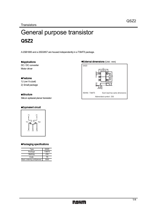
QSZ2中文资料
zElectrical characteristics (Ta=25°C)
Tr1
Parameter
Symbol Min.
Collector-base breakdown voltage BVCBO −30
Collector-emitter breakdown viltage BVCEO −30
IC= −10µA IC= −1mA IE= −10µA VCB= −30V VEB= −6V IC= −1mA, IB= −50mA VCE= −2V, IC= −100mA∗ VCE= −2V, IE=100mA, f=100MHz ∗ VCB= −10V, IE=0mA, f=1MHz
Tr2
Parameter Collector-base breakdown voltage Collector-emitter breakdown voltage Emitter-base breakdown voltage Collector cutoff current Emitter cutoff current Collector-emitter saturation voltage DC current gain Transition frequency Corrector output capacitance
COLLECTOR CURRENT : IC (A)
1 VCE= −2V Pulsed
0.1
Ta=100°C
Ta=25°C Ta= −40°C
0.01
0.001
0
0.5
1
1.5
BASE TO EMITTER CURRENT : VBE (V)
Fig.11 Grounded emitter propagation characteristics
- 1、下载文档前请自行甄别文档内容的完整性,平台不提供额外的编辑、内容补充、找答案等附加服务。
- 2、"仅部分预览"的文档,不可在线预览部分如存在完整性等问题,可反馈申请退款(可完整预览的文档不适用该条件!)。
- 3、如文档侵犯您的权益,请联系客服反馈,我们会尽快为您处理(人工客服工作时间:9:00-18:30)。
8
10
12
0
0
0.2
0.4
0.6
0.8
1.0
1.2
Ambient temperature Ta (°C)
Collector-emitter voltage VCE (V)
Base-emitter voltage VBE (V)
VCE(sat) IC
Collector-emitter saturation voltage VCE(sat) (V)
10 IC / IB = 10 2 400
hFE IC
VCE = 2 V
fT I E
120 VCB = 6 V Ta = 25°C
Forward current transfer ratio hFE
1
Transition frequency fT (MHz)
2 000
100
1 600 25°C 1 200 −25°C 800
Ta = 75°C
80
0.1 Ta = 75°C 25°C −25°C 0.01
60
40
400
20
0.001 0.1
1
10
100
0
1
10
100
1 000
0 −1
−10
−100
Collector current IC (mA)
Collector current IC (mA)
Emitter current IE (mA)
Parameter Collector-base voltage (Emitter open) Collector-emitter voltage (Base open) Emitter-base voltage (Collector open) Collector current Peak collector current Collector power dissipation Junction temperature Storage temperature Symbol VCBO VCEO VEBO IC ICP PC Tj Tstg Rating 50 20 25 300 500 150 150 −55 to +150 Unit V V V mA mA mW °C °C
This product complies with the RoHS Directive (EU 2002/95/EC).
Transistors
2SD1979
Silicon NPN epitaxial planar type
For low frequency amplification For muting For DC-DC converter ■ Features160 Nhomakorabea20
100
Collector current IC (mA)
16
9 µA 8 µA 7 µA 6 µA 5 µA 4 µA 3 µA 2 µA 1 µA
Collector current IC (mA)
IB = 10 µA
80
120
12
60
80
8
40
40
4
20
0
0
40
80
120
160
0
0
2
4
6
1 2
Unit: mm
(0.425)
0.3+0.1 –0.0 3 0.15+0.10 –0.05
1.25±0.10
2.1±0.1 5°
(0.65) (0.65) 1.3±0.1 2.0±0.2 10°
0.9±0.1
0.9+0.2 –0.1
■ Absolute Maximum Ratings Ta = 25°C
1
This product complies with the RoHS Directive (EU 2002/95/EC).
2SD1979
PC Ta
200
IC VCE
24 Ta = 25°C
120
IC VBE
VCE = 2 V 25°C Ta = 75°C −25°C
Collector power dissipation PC (mW)
Cob VCB
Collector output capacitance C (pF) (Common base, input open circuited) ob
12 f = 1 MHz IE = 0 Ta = 25°C
10
8
6
4
2
0
1
10
100
Collector-base voltage VCB (V)
2
SJC00233CED
Request for your special attention and precautions in using the technical information and semiconductors described in this book
(1) If any of the products or technical information described in this book is to be exported or provided to non-residents, the laws and regulations of the exporting country, especially, those with regard to security export control, must be observed. (2) The technical information described in this book is intended only to show the main characteristics and application circuit examples of the products, and no license is granted under any intellectual property right or other right owned by our company or any other company. Therefore, no responsibility is assumed by our company as to the infringement upon any such right owned by any other company which may arise as a result of the use of technical information described in this book. (3) The products described in this book are intended to be used for standard applications or general electronic equipment (such as office equipment, communications equipment, measuring instruments and household appliances). Consult our sales staff in advance for information on the following applications: – Special applications (such as for airplanes, aerospace, automobiles, traffic control equipment, combustion equipment, life support systems and safety devices) in which exceptional quality and reliability are required, or if the failure or malfunction of the products may directly jeopardize life or harm the human body. – Any applications other than the standard applications intended. (4) The products and product specifications described in this book are subject to change without notice for modification and/or improvement. At the final stage of your design, purchasing, or use of the products, therefore, ask for the most up-to-date Product Standards in advance to make sure that the latest specifications satisfy your requirements. (5) When designing your equipment, comply with the range of absolute maximum rating and the guaranteed operating conditions (operating power supply voltage and operating environment etc.). Especially, please be careful not to exceed the range of absolute maximum rating on the transient state, such as power-on, power-off and mode-switching. Otherwise, we will not be liable for any defect which may arise later in your equipment. Even when the products are used within the guaranteed values, take into the consideration of incidence of break down and failure mode, possible to occur to semiconductor products. Measures on the systems such as redundant design, arresting the spread of fire or preventing glitch are recommended in order to prevent physical injury, fire, social damages, for example, by using the products. (6) Comply with the instructions for use in order to prevent breakdown and characteristics change due to external factors (ESD, EOS, thermal stress and mechanical stress) at the time of handling, mounting or at customer's process. When using products for which damp-proof packing is required, satisfy the conditions, such as shelf life and the elapsed time since first opening the packages. (7) This book may be not reprinted or reproduced whether wholly or partially, without the prior written permission of Matsushita Electric Industrial Co., Ltd.
