STLC2410B中文资料
S3C2410中文手册第5章_存储器控制器

S3C2410A 中文数据手册(第五章)
杭州立宇泰电子有限公司编著(Version 1.0)
SDRAM的BANK地址引脚连接
表 5-2. SDRAM Bank 地址结构
Bank大小 2MB 4MB 8MB 16MB
32MB 64MB 128MBห้องสมุดไป่ตู้
总线宽度 x8 x16 x8 x16 x32 x16 x32 x8 x8 x16 x16 x32 x32 x8 x8 x16 x16 x32 x32 x8 x16 x16 x16 x32 x32 x16 x32 x8 x16 x32 x16 x32 x8 x32
0x307f_ffff
0x30ff_ffff
0x3000_0000 0x31ff_ffff
0x3000_0000 0x3000_0000
0x33ff_ffff
0x37ff_ffff
Bank 7
起始 0x3020_0000 0x3040_0000 0x3080_0000
地址
0x3100_0000
终址 地址
OM0 (操作模式0) 0 1 0 1
导入ROM 数据宽度 Nand Flash Mode
16-bit 32-bit Test Mode
存储器(SROM/SDRAM)地址引脚的连接
MEMORY ADDR. PIN
A0 A1
S3C2410A ADDR. @ 8-bit DATA BUS A0 A1
•••
x32
(8M x 16 x 4banks) x 2 ea
5.2.1nWAIT 引脚的作用
如果对每个bank使能WAIT功能,当对某个bank区进行访问时,nOE的低电平有效时间 就会在nWAIT引脚的控制下延长。从tacc-1时刻开始检测nWAIT的状态。在采样到nWAIT为 高电平后的下一个时钟,nOE将恢复高电平。nWAIT对nWE信号的作用与对nOE信号相同。
2410英贝特开发箱_课程设计说明书及代码
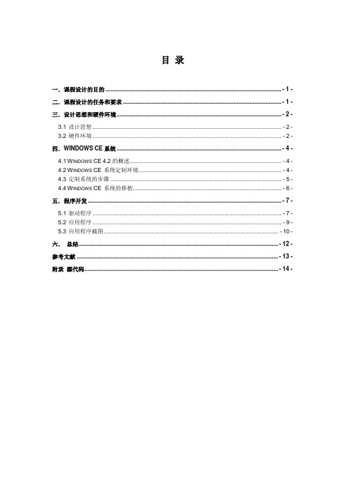
目录一.课程设计的目的 .............................................................................................................. - 1 -二.课程设计的任务和要求 ................................................................................................... - 1 -三.设计思想和硬件环境....................................................................................................... - 2 -3.1设计思想 (2)3.2硬件环境 (2)四.WINDOWS CE系统 ....................................................................................................... - 4 -4.1W INDOWS CE4.2的概述 (4)4.2W INDOWS CE系统定制环境 (4)4.3定制系统的步骤 (5)4.4W INDOWS CE系统的移植 (6)五.程序开发 ......................................................................................................................... - 7 -5.1驱动程序 (7)5.2应用程序 (9)5.3应用程序截图 (10)六.总结............................................................................................................................. - 12 -参考文献 .............................................................................................................................. - 13 -附录源代码......................................................................................................................... - 14 -一.课程设计的目的通过本课程的学习,使学生掌握Windows CE 4.2操作系统下,基于EduKit2410 III试验箱实现操作系统的定制、引导程序和操作系统的移植,以及设备驱动程序和应用程序的开发方法。
S3C2410中文手册第7章 时钟和功率管理

第七章时钟和功率管理概述时钟和功率管理模块由三部分组成:时钟控制,USB控制和功率控制。
S3C2410A的时钟控制逻辑能够产生系统所需要的时钟,包括CPU的FCLK,AHB总线接口的HCLK,和APB总线接口的PCLK。
S3C2410A有两个PLL,一个用于FCLK,HCLK,PCLK,另一个用于USB模块(48MHZ)。
时钟控制逻辑能够由软件控制不将PLL连接到各接口模块以降低处理器时钟频率,从而降低功耗。
S3C2410A有各种针对不同任务提供的最佳功率管理策略,功率管理模块能够使系统工作在如下4种模式:正常模式,低速模式,空闲模式和掉电模式。
正常模式:功率管理模块向CPU和所有外设提供时钟。
这种模式下,当所有外设都开启时,系统功耗将达到最大。
用户可以通过软件控制各种外设的开关。
例如,如果不需要定时器,用户可以将定时器时钟断开以降低功耗。
低速模式:没有PLL的模式。
与正常模式不同,低速模式直接使用外部时钟(XTIpll或者EXTCLK)作为FCLK,这种模式下,功耗仅由外部时钟决定。
空闲模式:功率管理模块仅关掉FCLK,而继续提供时钟给其他外设。
空闲模式可以减少由于CPU核心产生的功耗。
任何中断请求都可以将CPU从中断模式唤醒。
掉电模式:功率管理模块断开内部电源。
因此CPU和除唤醒逻辑单元以外的外设都不会产生功耗。
要执行掉电模式需要有两个独立的电源,其中一个给唤醒逻辑单元供电,另一个给包括CPU在内的其他模块供电。
在掉电模式下,第二个电源将被关掉。
掉电模式可以由外部中断EINT[15:0]或RTC唤醒。
功能描述时钟结构图7-1描述了时钟架构的方块图。
主时钟源由一个外部晶振或者外部时钟产生。
时钟发生器包括连接到一个外部晶振的振荡器和两个PLL(MPLL和UPLL)用于产生系统所需的高频时钟。
时钟源选择表7-1描述了模式控制引脚(OM3和OM2)和选择时钟源之间的对应关系。
OM[3:2]的状态由OM3和OM2引脚的状态在nRESET的上升沿锁存得到。
S3C2410_第六章NAND

S3C2410A中文数据手册(第六章)第六章 NAND FLASH控制器6.1概述 (2)6.2特性 (2)6.2.1自动导入模式步骤 (3)6.2.2NAND FLASH 模式配置 (3)6.2.3NAND FLASH 存储器时序 (4)6.2.4管脚配置 (4)6.2.5系统引导和NAND FLASH配置 (4)6.2.6NAND Flash存储空间分布 (5)6.3专用寄存器 (6)6.3.1NAND FLASH 配置(NFCONF)寄存器 (6)6.3.2NAND FLASH 命令设置(NFCMD)寄存器 (7)6.3.3NAND FLASH地址设置 (NFADDR)寄存器 (8)6.3.4NAND FLASH 数据 (NFDATA)寄存器 (8)6.3.5NAND FLASH ECC (NFECC) 寄存器 (9)第 1 页共 9 页S3C2410A中文数据手册(第六章).0)6.1概述当前,NOR flash存储器的价格比较昂贵,而SDRAM和NAND flash存储器的价格相对来说比较合适,这样就激发了一些用户产生希望从NAND flash启动和引导系统,而在SDRAM上执行主程序代码的想法。
S3C2410A恰好满足这一要求,它可以实现从NAND flash上执行引导程序。
为了支持NAND flash的系统引导,S3C2410A具备了一个内部SRAM缓冲器,叫做“Steppingstone”。
当系统启动时,NAND flash存储器的前面4KByte字节将被自动载入到Steppingstone中,然后系统自动执行这些载入的引导代码。
一般情况下,这4K的引导代码需要将NAND flash中程序内容拷贝到SDRAM中,在引导代码执行完毕后跳转到SDRAM执行。
使用S3C2410A内部硬件ECC功能可以对NAND flash的数据进行有效性的检测。
6.2特性z NAND Flash模式:支持读/擦/编程NAND flash存储器。
博创科技 UP-TECH S2410 P270 DVP 经典开发平台 硬件说明书
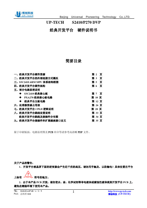
UP-TECH S2410/P270 DVP经典开发平台硬件说明书简要目录一、经典开发平台硬件资源第 2 页二、经典开发平台的外部连接方式概况第 3 页三、S3C2410 ARM MPU体系结构框图第 5 页四、经典开发平台硬件架构第 6 页五、部分电路原理说明S3C2410经典核心板第 7 页PXA270经典核心板电路第 10 页经典平台主板电路第 12 页六、处理器资源占用表第 26 页七、经典开发平台CPLD逻辑说明第 28 页八、经典开发平台跳线设置说明第 33 页经典开发平台跳线及接插件分布图第 34 页九、经典开发平台接插件和扩展插座接口定义第 35 页限于印刷版面,电路原理图及PCB丝印等请参考高清晰PDF文件。
关于产品的警告:1.开发平台液晶屏下面的逆变器会产生近千伏的高压,请勿用手触及,以防触电!具体位置在平台上标有符号的地方。
2.由于本产品PCB开放,请勿使水、油、化学试剂等导电液体或腐蚀性液体流到开发平台PCB上,避免在潮湿环境下使用本产品。
一、经典开发平台硬件资源1.核心板:A )S3C2410核心板:S3C2410 ARM CPU、64M SDRAM、64M NAND FLASH,通过280Pin精密插座与主板连接。
核心板上可以配置2M或4M容量的Nor Flash AM29LV160/320,硬件支持从NorFlash启动并可增加NandFlash容量。
B)PXA270核心板:PXA270 XScale CPU、64M SDRAM、64M NAND FLASH,16M Nor FLASH。
经典平台的核心板接口设计完全兼容博创的PXA270核心板和S3C2410核心板,在软件支持下,两个核心板在经典开发平台主板上均可以实现大部分硬件功能,完全可以替换原有的2410-S和270A系列产品。
2.双100M EtherNet网卡:由两片DM9000AE构成的双网卡,一般可只用其一。
2410话机手册

• 使用 (容量,特别是接入设备的容量) • 盗窃 (例如知识产权、金融资产或资费设备访问) • 偷听 (侵犯个人隐私) • 恶作剧 (制造无危害的麻烦,篡改) • 伤害 (例如,有害的篡改、数据丢失或变更,而不管其动机
信息技术设备抗扰度限值和测量方法, CISPR 24:1997 和 EN55024:1998,包括:
• 静电放电 (ESD) IEC 61000-4-2 • 抗辐射干扰度 IEC 61000-4-3 • 电器瞬态 IEC 61000-4-4 • 雷击效应 IEC 61000-4-5 • 抗传导干扰度 IEC 61000-4-6 • 主频率磁场 IEC 61000-4-8 • 电压跌落和变化 IEC 61000-4-11
通信地址:Globalware Solutions 200 Ward Hill Avenue Haverhill, MA 01835 USA Attention:Avaya Account Management
E-mail: totalware@
要获得文件的最新版本,请登录 Avaya 支持网站: /support。
目录
概述 . . . . . . . . . . . . . . . . . . . . . . . . . . . 7 耳机兼容性 . . . . . . . . . . . . . . . . . . . . . . . . 8 安全信息 . . . . . . . . . . . . . . . . . . . . . . . . 9
要获得美国责任方签名的 SdoC 的副本,可以联系当地销售代表,或 者登录以下网站:/support。
OURS-2410BP底板原理图
1
1
1பைடு நூலகம்
1
R10 10K D nTRST TDI TMS TCK TDO 1 nRESET 2 2
R13 10K 2
R14 10K 2
R15 10K 10K 1 3 5 7 9 11 13 15 17 19 CON4 1 3 5 7 9 11 13 15 17 19 2 4 6 8 10 12 14 16 18 20 2 4 6 8 10 12 14 16 18 20 2
J5 PHONE_PLUGIN AGND J4 PHONE_PLUGIN AGND 1 13 25 12 24 11 23 10 22 9 21 8 20 7 19 6 18 5 17 4 16 3 15 2 14 1 SLCT PE BUSY ACK# PD7 PD6 PD5 PD4 PD3 SLIN# PD2 INIT# PD1 ERR# PD0 AFD# STB# B
SDDATA1 SDDATA0 SDCLK SDCMD SDDATA3 SDDATA2
VDDRTC18V ETH_RX+ 6 TDP RDC RDN RXP RXC RXN 11 10 9
ETH_RCOM 7 ETH_RXOM0 2 S1 VDD33V 1 4 3 6 SWITCH 8
SD CARD
A K
R16
U4B GND VCC I O 4 9
U4D GND VCC I
C25
+
1
3 4
74LV14 7 7
74LV14 7 U4C I 74LV14 7 7 74LV14
74LV14
R9
470 2 R21 330 2
MULTI_ICE 1 1
U4A GND VCC I O 2 5
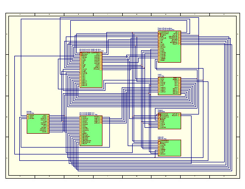
最小系统板AN2410SSB原理图
C
U5A 1 S1 + C7 10uF/16V 1 2
VDD33
R40 1K nLED_1 LED1 GREEN R37 1K LED2 GREEN R38 1K LED3 GREEN R39 1K LED4 R44 4.7K 1 2 R45 4.7K 1 2 R54 4.7K 1 2 R55 4.7K EINT15 EINT19 S5 1 2 EINT19 LED5 R24 1K POWER 3 4 EINT19 A EINT14 EINT15 S4 3 4 EINT15 EINT11 EINT14 S3 3 4 EINT14 GREEN EINT11 S2 3 4 EINT11 nLED_8 nLED_8 nLED_4 nLED_4 B nLED_2 nLED_2 nLED_1
UART VDD T1IN ROUT1 T2IN ROUT2 C1+ C111 12 10 9 1 nRTS0 nCTS0 TXD0 RXD0
CLOCK
D
VBUS VDD33 GND
6
V-
VCC 5 R27 10K D5 1N4148
U5C
C
15
C15 MAX3232 100nF
VSS
VBUS VDD33
D
0.4V/1a/30V
miniSMDC150
+ C1 10uF/16V
1
R53 C VDD33 3 U3 SPX1117M3 ADJ 1 IN OUT 2 R14 2.2K, 1% + C4 10uF/16V R14 2.2K 1.69K Vout 1.823V 1.995V R16 1K, 1% 3 VDD18 JP1 2 0 R9 0 VDD18_P
STLC2411中文资料

Min
Typ
Max
Unit
1.55
1.8
1.95
V
2.7
3.3
3.6
V
1.65
3.3
3.6
V
-40
+85
°C
3.3 I/O specifications
Depending on the interface, the I/O voltage is typical 1.8V (interface to the flash memory) or typical 3.3V (all the other interfaces). These I/Os comply with the EIA/JEDEC standard JESD8-B.
■ Supports Pitch-Period Error Concealment (PPEC) – Improves speech quality in the vicinity of interference – Improves coexistence with WLAN – Works at receiver, no Bluetooth implication
3 QUICK REFERENCE DATA
3.1 Absolute Maximum Ratings
Operation of the device beyond these conditions is not guaranteed. Sustained exposure to these limits will adversely affect device reliability.
0.15
V
Voh High level output voltage Ioh =-X mA
LTC2410IGN资料

TYPICAL APPLICATIO S
2.7V TO 5.5V 1µF 2 VCC LTC2410 REFERENCE VOLTAGE 0.1V TO VCC ANALOG INPUT RANGE –0.5VREF TO 0.5VREF 3 4 5 6 REF + REF – IN + IN – GND SDO CS 12 11
ELECTRICAL CHARACTERISTICS
REF + ≤ V
2.5V ≤ REF + ≤ VCC, REF – = GND, IN + = 0.75REF +, IN – = 0.25 • REF + 2.5V ≤ REF + ≤ VCC, REF – = GND, IN + = 0.25 • REF+, IN – = 0.75 • REF + 2.5V ≤ REF + ≤ VCC, REF – = GND, IN + = 0.25 • REF+, IN – = 0.75 • REF + REF + = 2.5V, REF – = GND, VINCM = 1.25V 5V ≤ VCC ≤ 5.5V, REF + = 5V, REF – = GND, VINCM = 2.5V 5V ≤ VCC ≤ 5.5V, REF + = 5V, VREF – = GND, GND ≤ IN – = IN + ≤ 5V, (Note 13)
三星芯片

一. Memory ControllerSDRAM:S3C2410提供了外接ROM、SRAM、SDRAM、NOR Flash、NAND Flash的接口。
S3C2410外接存储器的空间被分为8 BANKS,每BANK容量为128M:当访问BANKx(x从0到7)所对应的地址范围x*128M到(x+1)*128M-1 SDRAM使用BANK6,它的物理起始地址为6*128M=0x30000000。
SDRAM(刷新):之所以称为DRAM,就是因为它要不断进行刷新(Refresh)才能保留住数据,因此它是DRAM最重要的操作。
那么要隔多长时间重复一次刷新呢?目前公认的标准是,存储体中电容的数据有效保存期上限是64ms (毫秒,1/1000秒),也就是说每一行刷新的循环周期是64ms。
这样刷新速度就是:行数量/64ms刷新操作分为两种:自动刷新(Auto Refresh,简称AR)与自刷新(Self Refresh,简称SR)。
不论是何种刷新方式,都不需要外部提供行地址信息,因为这是一个内部的自动操作。
对于AR, SDRAM内部有一个行地址生成器(也称刷新计数器)用来自动的依次生成行地址。
由于刷新涉及到所有L-Bank,因此在刷新过程中,所有L-Bank都停止工作,而每次刷新所占用的时间为9个时钟周期(PC133标准),之后就可进入正常的工作状态,也就是说在这9 个时钟期间内,所有工作指令只能等待而无法执行。
SR则主要用于休眠模式低功耗状态下的数据保存,这方面最著名的应用就是STR(Suspend to RAM,休眠挂起于内存)。
在发出AR命令时,将CKE置于无效状态,就进入了SR模式,此时不再依靠系统时钟工作,而是根据内部的时钟进行刷新操作。
SDRAM(寄存器设置):本实验介绍如何使用SDRAM,这需要设置13个寄存器。
由于我们只使用了BANK6,大部分的寄存器我们不必理会:1.BWSCON:对应BANK0-BANK7,每BANK使用4位。
ARM微处理器 S3C2410的简介

ARM微处理器 S3C2410的简介1.1 ARM微处理器的介绍1)ARM微处理器的工作状态和工作模式从编程的角度看,ARM微处理器的工作状态有两种,可在两种状态之间切换:第一种为ARM状态,此时处理器执行32位的字对齐的ARM指令;第二种为Thumb状态,此时处理器执行16位的、半字对齐的Thumb指令。
2)ARM微处理器支持7种运行模式,分别为:用户模式(USR):ARM处理器正常程序执行的模式。
快速中断模式( FIQ ):用于高速数据传输或通道处理用于快速中断服务程序。
当处理器的快速中断请求引脚有效,且CPSR(6位)中F位为0时(开中断),会产生FIQ异常。
外部中断模式( IRQ ):用于通用的中断处理,当处理器的外部中断请求引脚有效,且CPSR(7位)中I位为0时(开中断),会产生IRQ异常。
系统的外设可通过该异常请求中服务。
特权模式或管理员模式(SVE):操作系统使用的保护。
执行软件中断SWI 指令和复位指令时,就进入管理模式,在对操作系统运行时工作在该模式下。
1.2 S3C2410微处理器1.2.1 概述S3C2410是韩国三星公司的一款基于ARM920T内核的16/32位RISC嵌入式微处理器,主要面向手持设备以及高性价比,低功耗的应用。
运行的频率可以达到203MHz。
ARM920T核由ARM9TDMI,存储管理单元(MMU)和高速缓存三部分组成。
其中MMU可以管理虚拟内存,高速缓存由独立的16KB地址和16KB数据高速Cache 组成。
ARM920T有两个协处理器:CP14和CP15。
CP14用于调试控制,CP15用于存储系统控制以及测试控制。
ARM920T体系结构框图图2-1 ARM920T体系结构框图1.2.2 S3C2410微处理器的结构S3C2410内部结构原理内部原理框图如下:图2-2S3C2410内部结构原理ARM 微处理器中共定义了37个编程可见寄存器,每个寄存器的长度均为32位。
H8S2140B中文简述

H8S/2140B中文简述H8S/2140B 群H8S/2140B群是由H8S/2000 CPU和系统构成所需的外围功能组成的微机(MCU)。
H8S/2000 CPU 内部为32位体系结构,具有16个16位通用寄存器和用于高速运行的精简优化指令集。
该H8S/2000 CPU可处理16M字节的线性地址空间。
作为系统构成所需的内置外围模块,该LSI备有作为总线主控器的数据传送控制器(DTC) 、ROM、RAM、8位PWM定时器(PWM)、14位PWM定时器 (PWMX)、16位自由运行定时器(FRT)、8位定时器(TMR)、定时器连接、看门狗定时器(WDT)、串行通信接口(SCI)、键盘缓冲控制器、主机接口X总线接口(XBS)、主机接口LPC接口(LPC) 、8位D/A转换器、10位A/D转换器和I/O端口,还可集成I2C总线接口(IIC)作为可选接口。
该群还提供了高功能的总线控制器,从而可以轻松快速地连接DRAM和其他种类的存储器。
对于该LSI中的ROM还提供了闪存版,此版具有灵活性,可及时进行改写,因此能对应从早期批量生产到大规模批量生产的各种情况,尤其适用于那些规格可能发生变化的应用器件。
技术手册H8S/2140B Group Hardware ManualKey Features:工作频率(MHz)/电源电压(V)H8S/2161B: 3V/10MHzH8S/2160B: 3V/10MHzH8S/2141B: 3V/10MHzH8S/2140B: 3V/10MHzH8S/2145B: 3V/10MHz, 5V/20MHzH8S/2148B: 3V/10MHz, 5V/20MHz可在1个状态内执行标准指令。
内置存储器H8S/2161B(128kB/4kB)H8S/2160B(64kB/4kB)H8S/2141B(128kB/4kB)H8S/2140B(64kB/4kB)H8S/2145B(256kB/8kB)H8S/2148B(128kB/4kB)I/O端口(输入/输出)74个管脚(H8S/2140B, 2141B, 2145B, 2148B)114个管脚(H8S/2160B, 2161B)掉电模式H8S/2148 群和H8S/2149、H8S/2169群实现了功能扩展。
Adaptec 2410SA 说明书

Adaptec2410SA 用户手册注意:RAID卡对静电非常敏感,必须小心操作。
把RAID卡从包装盒中取出后,应将其元器件面向上,放于防静电表面或绝缘泡沫块上。
不要将RAID卡在任何表面滑动。
在RAID卡操作过程中请佩带防静电手环或者使用其他防静电措施。
一、RAID知识介绍RAID的全称是独立硬盘冗余阵列(Redundant Array of Independent Disks)或廉价硬盘冗余阵列(Redundant Array of Inexpensive Disks)。
RAID出现的最初目的是将多个容量较小的硬盘合并成为一个大容量的“逻辑盘”,实现硬盘容量的增加性能提升。
随着RAID技术的发展,现在可以选择不同的RAID阵列类型以满足硬盘容量、数据冗余、或者存储系统性能等需要。
RAID技术主要有三个特点:第一,通过对硬盘上数据的条带化,实现对数据成块存取,减少硬盘的机械寻道时间,提高数据存取速度;第二,通过对一个阵列中的几块硬盘同时读取,减少硬盘的机械寻道时间,提高数据存取速度;第三,通过镜像或者存储奇偶校验信息的方式,实现对数据的冗余保护。
经常应用的RAID阵列主要分为RAID 0、RAID 1、RAID 5和RAID 10。
1、RAID0通过同时对硬盘进行读写从而提供最大I/O性能的非冗余的硬盘阵列。
RAID0通过对多个硬盘同时存取,减少了由硬盘机械系统引起的时间延迟,能提高磁盘子系统读写性能,但由于没有提供数据冗余功能,所以如果硬盘阵列中的任意一个硬盘发生损坏,都会造成阵列所有数据的丢失。
(如图1-1)图1-1 RAID0原理2、RAID1也称硬盘镜像。
系统将数据同时重复的写入两个硬盘,但是在操作系统中表现为一个逻辑盘。
所以如果一个硬盘发生了故障,另一个硬盘中仍然保留了一份完整的数据,系统仍然可以照常工作。
系统可以同时从两个硬盘读取数据,所以会提高硬盘读的速度。
(如图1-2)图1-2 RAID1原理3、RAID10先对若干对物理硬盘分别做RAID1,再将这若干个RAID1逻辑盘做成RAID0阵列。
DMC2410硬件手册v1.1
PCI总线
PCI总线 控制芯片 同时启停STA、STP 专用运动控制
芯片
外部输入+24V
非隔离
隔离
非隔离
脉冲/方向、 通用输出
PUL/DIR、 OUTPUT
通用输入 机械接口 伺服接口 编码器
INPUT
±EL、 ±SD、 ORG
INP、ALM、ERC、 SEVON、RDY
第七章 疑难解决 ......................................... 33
第八章 抗干扰措施........................................ 35
第九章 DMC2410 规格参数 ................................ 36
z 功能强大的 MOTION2410 测试软件
1.3 主要技术指标
z 每轴最大输出脉冲频率 5MHZ z 任意两轴圆弧插补功能 z 梯形/S 形对称或非对称速度曲线运动 z 运动中可改变目标位置和速度 z 四轴高速位置信息锁存输入 z 数字 IO 口最多可达 32 进 28 出 z 每轴编码器输入脉冲频率最大 4MHZ z 同一计算机系统中最多支持 8 块卡 z 支持手轮和 JOG 功能 z DMC2410 DLL 函 数 库 适 用 于 WINDOWS
雷赛公司引进美国 MOTION ENGINEERING 公司的先进技术,为 DMC2410 设计了一套易 学易用、功能丰富的运动函数库,大大缩短了用户应用软件开发、调试时间。随卡免费提供的 MOTION2410 软件,不但可以演示和测试 DMC2410 的绝大多数控制功能,而且还可方便客户 测试控制卡及电机控制系统硬件。
2410存储器系统及串口

主要优点:内存地址空间与I/O接口地址空间分开,互不影响,译码电 路较简单,并设有专门的I/O指令,所以编程序易于区分,且执行时间 短,快速性好。 缺点:只用I/O指令访问I/O端口,功能有限且要采用专用I/O周期和专 用I/O控制线,使微处理器复杂化。
23
I/O接口的编址方式——内存映射
系统地址空间 应用使用 应用使用 地址空间 地址空间 I/O设备硬件
31
UART控制框图
并行总线 数据接收器
发送FIFO(16 Byte)
发送移相器
TXDn
控制单元
波特率发生器
时钟源
接收移相器
RXDn
接收FIFO(16 Byte)
数据接收器
32
异步串行通讯简介
在一条传输线上完成单向传输。 将传输数据的字符一位接一位的传送。 接收方对于同一条线上的一连串连续数学 信号,首先将其分割成位,再按位组成字 符。 每个字符需要确定起始位和结束位,字符 与字符间还可能有长度不定的空闲时间, 因此传输效率较低。
17
可靠性和耐用性
在NAND中每块的最大擦写次数是 100万次,而NOR的擦写次数是10万 次 位交换的问题NAND flash中更突出, 需要ECC纠错 NAND flash中坏块随机分布,需要 通过软件标定——产品量产的问题
18
嵌入式系统中应用RAM的情况
19
本节提要
1 基于ARM的硬件系统体系结构 2 存储器接口设计 3 4 5 6 I/O系统设计
CPU DMA 控制器
主存储器
I/O设备
25
字符模式设备与块模式设备
根据设备如何处理与系统之间的数据传输方法 可将设备分为字符模式设备和块模式设备 字符模式设备:允许非结构的数据传输。数据 传输典型地采用串行的形式,每次一个字节; 字符设备通常是简单的设备,如串口、键盘等; 当系统到设备的传输速率高于设备的处理速率 时,设备驱动程序开设缓冲区,缓存这些数据;
2410的IO口
为满足不同系统设计要求,可以容易地通过软件对它们进行配
置。每个引脚的功能必须在启动主程序之前进行定义。
如果某些引脚的复用功能(第二功能)没有使用,那么可以先 将该引脚设置为I/O口。
•
杂项控制寄存器以及外部中断控制寄存器(EXTINTN)
端口控制寄存器(GPACON~GPHCON)
• 在S3C2410芯片中,大部分引脚是复用的,所以必须对每个引 脚进行配置。端口控制寄存器定义了每个引脚的功能。
端口数据寄存器(GPADAT~GPHDAT)。
• 如果该端口定义为输出端口,那么可以向 PnDAT 的相应位写
13.外部中断屏蔽寄存器
表5.21 外部中断屏蔽寄存器
14.外部中断挂起寄存器
表5.22 外部中断挂起寄存器
15.通用状态寄存器
表5.23 外部中断状态寄存器
5.3 I/O口编程控制
•
I/O口上拉寄存器和控制寄存器设置。首先确定I/O口工作模式 ,如果是工作在第二功能状态,则上拉电阻功能禁止,即
若对 GPCUP [15: 0 」的某一位清 0 ,则允许端口 C 相应引脚的上拉功能,否则禁止
上拉功能。
PORT C 的功能配置
表5.6 端口C控制寄存器(GPCCON)的配置
4. 端口D控制寄存器(GPDCON、GPDDAT和GPDUP)功 能配置
表5.7 端口D控制寄存器(GPCCON)的配置
如果端口D被配置为输入端口,则可以从引脚读入相应外部输入源输入的数据。如 果端口D被配置为输出端口,则向寄存器写的数据可以被送往相应的引脚。如果端 口D被配置为第二功能引脚,则从该引脚读出的数据不确定。
- 1、下载文档前请自行甄别文档内容的完整性,平台不提供额外的编辑、内容补充、找答案等附加服务。
- 2、"仅部分预览"的文档,不可在线预览部分如存在完整性等问题,可反馈申请退款(可完整预览的文档不适用该条件!)。
- 3、如文档侵犯您的权益,请联系客服反馈,我们会尽快为您处理(人工客服工作时间:9:00-18:30)。
1/20STLC2410BJanuary 2004Rev. 2.01FEATURES■Bluetooth ® V1.1 specification compliant ■Point-to-point, point-to-multi-point (up to 7 slaves) and scatternet capability■Asynchronous Connection-Less (ACL) link support giving data rates up to 721kbps■Synchronous Connection-Oriented (SCO) link ■Standard BlueRF bus interface ■ARM7TDMI CPU –32-bit Core–Run from 13MHz external clock–Support of 32 kHz crystal for low power mode ■Memory organization –64KByte on-chip RAM –4KByte on-chip boot ROM–Programmable external memory interface (EMI)–8-bit or 16-bit external data bus–Up to 3 programmable chip-select signals –Hold-acknowledge bus arbitration support ■HW support for all packet types –ACL: DM1, 3, 5 and DH1, 3, 5–SCO: HV1, 2, 3 and DV1■Communication interfaces–Serial Synchronous Interface–Two enhanced 16550 UART's with 128 byte fifo depth–12Mbps USB interface–Fast master I2C bus interface –Multi slot PCM interface –16 programmable GPIO–2 external interrupts and various interrupt possibilities through other interfaces ■Ciphering support for up to 128-bit key■Receiver Signal Strenght Indication (RSSI) support for power-controlled links■Separate control for external power amplifier (PA) for power class1 support.■Software support–Low level (up to HCI) stack or embedded stack with profiles–Support of UART and USB HCI transport layers ■Idle and power down modes –Ultra low power in idle mode –Low standby current■Extended temperature range■Compliant to automotive specification AEC-Q1001.1Applications FeaturesTypical applications in which the STLC2410B can be used are:■Portable computers, PDA ■Modems■Handheld data transfer devices ■Cameras■Computer peripherals■Other type of devices that require the wireless communication provided by Bluetooth ®■Cable replacement2DESCRIPTIONThe STLC2410B offers a compact and complete solution for short-range wireless connectivity. It in-corporates all the lower layer functions of the Blue-tooth ® protocol.The microcontroller allows the support of all data packets of Bluetooth ® in addition to voice. The em-bedded controller can be used to run the Blue-tooth ® protocol and application layers if required.The software is located in an external memory ac-cessed through the external memory interface.BLUETOOTH ® BASEBAND器件交易网STLC2410B2/203QUICK REFERENCE DATA3.1Absolute Maximum RatingsOperation of the device beyond these conditions is not guaranteed.Sustained exposure to these limits will adversely affect device reliability Table 1. Absolute Maximum Ratings3.2Operating RangesOperating ranges define the limits for functional operation and parametric characteristics of the device.Functionality outside these limits is not implied.Table 2. Operating Ranges3.3I/O specificationsDepending on the interface, the I/O voltage is typical 1.8V (interface to the flash memory) or typical 3.3V (all the other interfaces). These I/Os comply to the EIA/JEDEC standard JESD8-B.3.3.1Specifications for 3.3V I/OsTable 3. LVTTL DC Input Specification (3V<V DDIO <3.6V)Table 4. LVTTL DC Output Specification (3V<V DDIO <3.6V)Note 1 : X is the source/sink current under worst case conditions according to the drive capability. (See table 8, pad information for value of X).Symbol ConditionsMin Max Unit V DD Supply voltage core V SS - 0.52.5V V DDIO Supply voltage I/O4V V IN input voltage on any digital pin V SS - 0.5V DDIO + 0.3V T amb Operating ambient temperature -40+85°C T stg Storage temperature -65+150°C T leadLead temperature < 10s+240°CSymbol ConditionsMin Typ Max Unit V DD Supply voltage digital core and emi pads 1.55 1.8 1.95V V DDIO Supply voltage digital IO 2.7 3.33.6V T ambOperating ambient temperature-40+85°CSymbol ParameterConditionsMinTypMax Unit V il Low level input voltage 0.8V V ih High level input voltage 2V V hystSchmitt trigger hysteresis0.4VSymbol ParameterConditions MinTypMax Unit Note V ol Low level output voltageI ol = X mA0.15V 1V ohHigh level output voltage I oh =-X mAV DDIO -0.15V1器件交易网3/20STLC2410B3.3.2Specifications for 1.8V I/OsTable 5. DC Input Specification (1.55V<V DD <1.95V)Table 6. DC Output Specification (1.55V<V DD <1.95V)Note 1 : X is the source/sink current under worst case conditions according to the drive capability. (See table 8, pad information for value of X).3.4Current ConsumptionTable 7. Typical power consumption of the STLC2410B and External Flash using UART (VDD =VDD Flash = PLLVDD = 1.8V, VDDIO = 3.3V)Symbol ParameterConditionsMinTypMax Unit V il Low level input voltage 0.35*V DDV V ih High level input voltage 0.65*V DDV V hys tSchmitt trigger hysteresis0.20.30.5VSymbol ParameterConditions MinTypMax Unit Note V ol Low level output voltage I ol = X mA 0.15V 1V ohHigh level output voltageI oh =-X mAV DD -0.15V1STLC2410B StateCoreIOUnitSlaveMaster Standby (no low power mode) 5.10 5.100.13mA Standby (low power mode enabled)0.940.940.13mA ACL connection (no transmission)7.60 6.990.13mA ACL connection (data transmission)7.907.200.13mA SCO connection (no codec connected)8.707.900.14mA Inquiry and Page scan (low power mode enabled)127n.a.5µA Low Power mode (32 kHz crystal)2020µA器件交易网STLC2410BFigure 1. Block Diagram and Electrical Schematic4/205/20STLC2410B4PINOUTFigure 2. Pinout (Bottom view)4.1Pin Description and AssignmentTable4 : STLC2410B pinlist shows the pinout of STLC2410B; there are 107 digital functional pins and 22supply pins. The column "PU/PD" shows the pads implementing an internal weak pull-up/down, to fix value if the pin is left open. This can not replace an external pull-up/down.The pads are grouped according to two different power supply values, as shown in column "VDD":–V1 for 3.3 V typical 2.7 - 3.6 V range –V2 for 1.8 V typical 1.55 - 1.95 V rangeFinally the column "DIR" describes the pin directions:–I for inputs –O for outputs –I/O for input/outputs –O/t for tristate outputs器件交易网STLC2410B6/20Table 8. Pin ListNamePin #DescriptionDIRPU/PDVDDPADInterface to external memory int1D2External Interrupt used also as external wakeup I (1)V1CMOS, 3.3V TTL compatible schmitt trigger int2D1Second external interruptI (1)boot G14Select external boot from EMI or internal from ROM I (1)V2CMOS 1.8Vwait H12EMI external wait signal (left open)I PDrdn P1External read O V2CMOS 1.8V4mAslew rate controlwrn N2External writeO csn0P2External chip select bank 0O csn1M3External chip select bank 1O csn2N3External chip select bank 2O addr0 P3External address bit 0O addr1 P4External address bit 1O addr2 M5External address bit 2O addr3 N5External address bit 3O addr4 P5External address bit 4O addr5 M6External address bit 5O addr6 N6External address bit 6O addr7 P6External address bit 7O addr8 P7External address bit 8O addr9 N7External address bit 9O addr10 M7External address bit 10O addr11 P8External address bit 11O addr12 N8External address bit 12O addr13 M8External address bit 13O addr14 P9External address bit 14O addr15 P10External address bit 15O addr16 N10External address bit 16O addr17 M10External address bit 17O addr18 P11External address bit 18O addr19 N11External address bit 19O data0 M11External data bit 0I/O PD V2CMOS 1.8V 4mA slew rate controldata1 P12External data bit 1I/O PD data2 N12External data bit 2I/O PD data3 P14External data bit 3I/O PD data4 N13External data bit 4I/O PD data5N14External data bit 5I/OPD器件交易网7/20STLC2410Bdata6 M12External data bit 6I/O PD V2CMOS 1.8V4mAslew rate controldata7 M13External data bit 7I/O PD data8 M14External data bit 8I/O PD data9 K13External data bit 9I/O PD data10 K14External data bit 10I/O PD data11 J12External data bit 11I/O PD data12 J13External data bit 12I/O PD data13 J14External data bit 13I/O PD data14 H14External data bit 14I/O PD data15H13External data bit 15I/OPDSPI interface spi_frm L3Synchronous Serial Interface frame sync I/O V1CMOS, 3.3V TTL compatible, 2mAtristateslew rate control schmitt trigger spi_clkM1Synchronous Serial Interface clockI/Ospi_txd M2Synchronous Serial Interface transmit data O/tV1CMOS, 3.3V TTL compatible, 2mA slew rate control spi_rxd N1Synchronous Serial Interface receive data I(1)V1CMOS, 3.3V TTL compatible schmitt triggerUART interface uart1_txdC2Uart1 transmit dataO/tV1CMOS, 3.3V TTL compatible, 2mA slew rate control uart1_rxdC3Uart1 receive dataI(2)V1CMOS, 3.3V TTL compatible schmitt trigger uart2_o1J1Uart2 modem outputOV1CMOS, 3.3V TTL compatible, 2mA slew rate control uart2_o2J2Uart2 modem outputO/tV1CMOS, 3.3V TTL compatible, 2mA slew rate control uart2_i1H2Uart2 modem input I (2)V1CMOS, 3.3V TTL compatible uart2_i2H3Uart2 modem input I (2)V1uart2_io1J3Uart2 modem input/output I/O (2)V1CMOS, 3.3V TTL compatible, 2mA tristate slew ratecontrol uart2_io2K1Uart2 modem input/output I/O (2)V1uart2_txdH1Uart2 transmit dataO/tV1CMOS, 3.3V TTL compatible, 2mA slew rate controlTable 8. Pin List (continued)Name Pin #DescriptionDIR PU/PD VDDPAD器件交易网STLC2410B8/20uart2_rxdG3Uart2 receive dataI(2)V1CMOS, 3.3V TTL compatibleI2C interface i2c_dat C1I2C data pin I/O (3)V1CMOS, 3.3V TTL compatible, 2mAtristateslew rate controli2c_clkD3I2C clock pinI/O(3)V1USB interface usb_dn G1USB - pin I/O (1)V1usb_dpG2USB + pinI/O(1)V1GPIO interface gpio0 F14Gpio port 0I/O PU V1CMOS, 3.3V TTL compatible, 4mAtristate slew rate control gpio1 F13Gpio port 1I/O PU gpio2 F12Gpio port 2I/O PU gpio3E14Gpio port 3I/OPUV1CMOS, 3.3V TTL compatible, 4mAtristate slew rate control schmitt trigger gpio4 E13Gpio port 4I/O PU V1CMOS, 3.3V TTL compatible, 4mAtristate slew rate controlgpio5 E12Gpio port 5I/O PU gpio6 D13Gpio port 6I/O PU gpio7 D12Gpio port 7I/O PU gpio8 C14Gpio port 8I/O PU V1CMOS, 3.3V TTL compatible, 2mAtristate slew rate controlgpio9 A14Gpio port 9I/O PU gpio10 B13Gpio port 10I/O PU gpio11 A13Gpio port 11I/O PU gpio12 C12Gpio port 12I/O PU gpio13 B12Gpio port 13I/O PU V1CMOS, 3.3V TTL compatible, 2mAtristate slew rate controlgpio14 A12Gpio port 14I/O PU gpio15C11Gpio port 15I/OPUClock and test pins xin A1System clock I V1CMOS, 3.3V TTL compatible schmitt trigger nresetB2ResetI sys_clk_req B1System clock requestI/OV1CMOS, 3.3V TTL compatible, 2mAtristate slew rate controllpo_clk_p G13Low power oscillator + / Slow clock input I (1)V2lpo_clk_n G12Low power oscillator -O testA2Test modeIPDV1CMOS, 3.3V TTL compatibleTable 8. Pin List (continued)Name Pin #DescriptionDIR PU/PDVDD PAD 器件交易网9/20STLC2410B(1) Should be strapped to vssio if not used (2) Should be strapped to vddio if not used (3) Should have a 10 kOhm pull-up if not used.JTAG interface ntrst A3JTAG pin I PDV1CMOS, 3.3V TTL compatible tckB3JTAG pinI(1)V1CMOS, 3.3V TTL compatible schmitt trigger tms C4JTAG pin I PU V1CMOS, 3.3V TTL compatible tdi A4JTAG pinI PUtdoB4JTAG pin (should be left open)O/tV1CMOS, 3.3V TTL compatible, 2mA slew rate controlPCM interface pcm_a F2PCM data I/O PD V1CMOS, 3.3V TTL compatible, 2mAtristate slew rate control pcm_b F1PCM data I/O PD pcm_sync E1PCM 8kHz sync I/O PD pcm_clkF3PCM clockI/OPDV1CMOS, 3.3V TTL compatible, 2mAtristate slew rate control schmitt triggerRadio interface brclk B10Transmit clock I (1)V1CMOS, 3.3V TTL compatible schmitt trigger brxd A10Receive dataI bmiso C9RF serial interface input data I (1)V1CMOS, 3.3V TTL compatiblebnden B9RF serial interface control O V1CMOS, 3.3V TTL compatible, 2mA slew rate controlbmosi A9RF serial interface output data O bdclk A8RF serial interface clock O btxd B8Transmit data O bsen C8Synthesizer ON O bpaen A7Open PLL O brxen A6Receive ON O btxen B6Transmit ON O bpktctl C6Packet ON O ant_swA5Antenna switchOV1CMOS, 3.3V TTL compatible, 8mA slew rate controlTable 8. Pin List (continued)NamePin #DescriptionDIRPU/PDVDDPAD器件交易网STLC2410B10/20Table 4. Pin List (continued)Name Pin #DescriptionPower Supply vsspll D14PLL groundvddpll C13 1.8V supply for PLL vdd B7 1.8V Digital supply vdd K2 1.8V Digital supply vdd L12 1.8V Digital supply vdd L14 1.8V Digital supply vdd M4 1.8V Digital supply vdd N9 1.8V Digital supply vddio A11 3.3V I/O's supply vddio B5 3.3V I/O's supply vddio E3 3.3V I/O's supply vddio L1 3.3V I/O's supply vss C7Digital ground vss K3Digital ground vss K12Digital ground vss L13Digital ground vss M9Digital ground vss N4Digital ground vssio C5I/O's ground vssio C10I/O's ground vssio E2I/O's ground vssio L2I/O's ground器件交易网5.1Baseband5.1.1OverviewThe baseband is fully compliant with the Bluetooth® specification 1.1, including:–7 slaves support.–Asynchronous Connection-Less (ACL) link support giving data rates up to 721kb per second.–Synchronous Connection-Oriented (SCO) link with support for 1 voice channel over the air interface.–HW support for all packet types:–ACL: DM1, 3, 5 and DH1, 3, 5.–SCO: HV1, 2, 3, and DV1.–Support for three PCM channels in the PCM interface.–Architecture gives ultra-low power consumption.–Ciphering support for up to 128-bit, configurable by software.–Receiver Signal Strenght Indication (RSSI) support for power-controlled links.–Flexible voice formats to Host and over air (CVSD, PCM 16/8-bit, A-law, µ-law).–High quality filtering of voice packets enabling excellent audio quality.–Point-to-multipoint support.–Scatternet support, communication between two simultaneously running piconets.–Full Bluetooth® software stack available.–Low level link controller.–Specific external power amplifier (PA) control for class1 support.–Extended wake-up and interrupt functionality for HID support.5.1.2Processor and memory–ARM7TDMI.–64Kbyte of static RAM.–4Kbyte of metal programmable ROM–Extension of the ARM Bus to handle external program FLASH or RAM or dedicated peripherals.–Data bus in byte or half word format (8-bit or 16-bit).–Address bus 20-bit wide to support 1 Mbyte within each bank.–Direct Support for 3 external devices.–Access to slow peripherals.6.1SYSTEM CLOCKThe STLC2410B works with a single clock provided on the XIN pin. The value of this external clock should be 13MHz ±20ppm (overall).6.1.1SLOW CLOCKThe slow clock is used by the baseband as reference clock during the low power modes. Compared to the 13MHz clock, the slow clock only requires an accuracy of ±250ppm (overall).Several options are foreseen in order to adjust the STLC2410B behaviour according to the features of the radio used:–if the system clock (e.g. 13MHz) is not provided at all times (power consumption saving) and no slow clock is provided by the system, a 32 kHz crystal must be used by the STLC2410B (default mode).–if the system clock (e.g. 13MHz) is not provided at all times (power consumption saving) and the system provides a slow clock at 32kHz or 3.2kHz, this signal in simply connected to the STLC2410B (lpo_clk_p).–if the system clock (e.g. 13MHz) is provided at all times, the STLC2410B generates from the 13MHz reference clock an internal 32kHz clock. This mode is not an optimized mode for power consumption.6.2BOOT PROCEDUREThe boot code instructions are the first that ARM7TDMI executes after an HW reset. All the internal de-vice's registers are set to their default value.There are 2 types of boot:–external flash boot.When boot pin is set to `1` (connected to VDD), the STLC2410B boots on its external memory which is normally a flash memory.–UART download boot from ROM.When boot pin is set to `0` (connected to GND), the STLC2410B boots on its internal ROM (needed to download the new firmware).When booting on the internal ROM, the STLC2410B will monitor the UART interface for approximately 1.4 second. If there is no request for code downloading during this period, the ROM jumps to external flash.6.3CLOCK DETECTIONThe STLC2410B has a automatic slow clock frequency detection (32kHz, 3.2kHz or none).6.4MASTER RESETWhen the device's reset is held active (NRESET is low), all two uart txd pins (UART1_TXD and UART2_TXD) are driven low. When the NRESET returns high, the device starts to boot.Remark: The device should be held in active reset for minimum 20ms in order to guarantee a complete reset of the device.6.5INTERRUPTS/WAKE-UPThe external pins int1 and int2, and up to 8 GPIOs can be used both as external interrupt source and as wake-up source. In addition the chip can be woken-up by USB or Uart Rx.7INTERFACES7.1UART InterfaceThe chip contains two enhanced (128-byte FIFO depth, sleep mode, 127 Rx and 128 Tx interrupt tresh-olds) UARTs named UART1 and UART2 compatible with the standard M16550 UART.For UART1, only Rx and Tx signals are available (mainly used for debug purposes and in test mode).UART2 features:–standard HCI UART transport layer:–all HCI commands as described in the Bluetooth ® specification 1.1–ST specific HCI command (check STLC2410B Software Interface document for more information)–RXD, TXD, CTS, RTS on permanent external pins –128-byte FIFOs, for transmit and for receive –Default configuration: 57.6 kbits/s–Specific HCI command to change to the following baud rates:Table 9. List of supported baud rates7.2Synchronous Serial InterfaceThe Synchronous Serial Interface is a flexible module that supports full-duplex and half-duplex synchro-nous communications with external devices in Master and Slave mode. It allows the STLC2410B to com-municate with peripheral devices.The Synchronous Serial Interface is also capable of inter processor communications in a multiple-master system. This interface is flexible enough to interface directly with numerous standard product peripherals.This Synchronous Serial Interface peripheral features:–full duplex, four-wire synchronous transfers.–Microwire half duplex transfer using 8-bit control message –programmable clock polarity and phase.–transmit data pin tri state able when not transmitting –Master or Slave operation–Programmable clock bit rate up to XIN/4–Programmable data frame from 4 bits to 16 bits.–Independent transmit and receive 16 words FIFO.–Internal loopback7.3I2C InterfaceThe I2C port is used both to connect to an external E2PROM and to access I2C peripherals like the STw5094 Codec. The I2C implemented in the STLC2410B is a master I2C, it has the full control of the I2C bus at all time. I2C slave functionality is not supported, so any other I2C attached to the I2C bus must be slave, otherwise bus contention will occur.Baud rate–57.6 k (default)4800921.6k 38.4 k 2400460.8 k 28.8 k 1800230.4 k 19.2 k 1200153.6 k 14.4 k 900115.2 k 960060076.8 k7200300器件交易网Figure 3. I2C BUS master flow diagram7.4USB InterfaceThe USB interface is compliant with the USB 2.0 full speed specification. Max throughput on the USB in-terface is 12 Mbit/s.Figure 4 gives an overview of the main components needed for supporting the USB interface, as specified in the Bluetooth® Core Specification ( Part H:2). For clarity, the serial interface (including the UART Trans-port Layer) is also shown.Figure 4. USB InterfaceThe USB device registers and FIFOs are memory mapped. The USB Driver will use these registers to ac-cess the USB interface. The equivalent exists for the HCI communication over UART.For transmission to the host, the USB & Serial Drivers interface with the HW via a set of registers and FIFOs, while in the other direction, the hardware may trigger the Drivers through a set of interrupts (iden-tified by the RTOS, and directed to the appropriate Driver routines).7.5JTAG InterfaceThe JTAG interface is compliant with the JTAG IEEE Std 1149.1. Its allows both the boundary scan of the digital pins and the debug of the ARM7TDMI application when connected with the standard ARM7 devel-opment tools.7.6RF InterfaceThe STLC2410B radio interface is compatible to BlueRF (unidirectional RxMode2 for data and unidirec-tional serial interface for control).7.7PCM voice interfaceThe voice interface is a direct PCM interface to connect to a standard CODEC (e.g. STw5093 or STw5094) including internal decimator and interpolator filters. The data can be linear PCM (13-16bit), µ-Law (8bit) or A-Law (8bit). By default the codec interface is configured as master. The encoding on the air interface is programmable to be CVSD, A-Law or µ-Law.The PCM block is able to manage the PCM bus with up to 3 timeslots.PCM clock and data are in master mode available at 2 MHz or at 2.048 MHz to allow interfacing of stan-dard codecs.The four signals of the PCM interface are:–PCM_CLK : PCM clock –PCM_SYNC : PCM 8kHz sync –PCM_A : PCM data–PCM_B : PCM dataDirections of PCM_A and PCM_B are software configurable.Figure 5. PCM (A-law, µ-law) standard modeFigure 6. Linear modeTable 10. PCM interface timing.Symbol DescriptionMinTypMaxUnitPCM Interface F pcm_clk Frequency of PCM_CLK (master)-2048kHz F pcm_sync Frequency of PCM_SYNC 8kHz t WCH High period of PCM_CLK 200ns t WCL Low period of PCM_CLK 200ns t WSH High period of PCM_SYNC200ns t SSC Setup time, PCM_SYNC high to PCM_CLK low 100ns t SDC Setup time, PCM_A/B input valid to PCM_CLK low 100ns t HCD Hold time, PCM_CLK low to PCM_A/B input invalid 100ns t DCDDelay time, PCM_CLK high to PCM_A/B output valid150ns器件交易网Figure 7. PCM interface timing8HCI UART TRANSPORT LAYERThe UART Transport Layer is specified by the Bluetooth® SIG ( Part H:4), and allows HCI level commu-nication between a host controller (STLC2410B) and a host (e.g. PC), via a RS232 interface.The objective of this HCI UART Transport Layer is to make it possible to use the Bluetooth® HCI over a serial interface between two UARTs on the same PCB. The HCI UART Transport Layer assumes that the UART communication is free from line errors.8.1UART SettingsThe HCI UART Transport Layer uses the following settings:–Baud rate: Configurable (Default baud rate: 57.6 kbits/s)–Number of data bits: 8–Parity bit: no parity–Stop bit: 1 stop bit–Flow control: RTS/CTS–Flow-off response time: 3 msFlow control with RTS/CTS is used to prevent temporary UART buffer overrun. It should not be used for flow control of HCI, since HCI has its own flow control mechanisms for HCI commands, HCI events and HCI data.If CTS is 1, then the Host/Host Controller is allowed to send.If CTS is 0, then the Host/Host Controller is not allowed to send.The flow-off response time defines the maximum time from setting RTS to 0 until the byte flow actually stops. The signals should be connected in a null-modem fashion; i.e. the local TXD should be connected to the remote RXD and the local RTS should be connected to the remote CTS and vice versa.Figure 8. UART Transport Layer9HCI USB TRANSPORT LAYERThe USB Transport Layer has been specified by the Bluetooth ® SIG (Part H:2), and allows HCI level com-munication between a host controller (STLC2410B) and a host (e.g. PC), via a USB interface. The USBTransport Layer is completely implemented in SW. It accepts HCI messages from the HCI Layer, prepares it for transmission over a USB bus, and sends it to the USB Driver. It reassembles the HCI messages from USB data received from the USB Driver, and sends these messages to the HCI Layer. The Transport Lay-er does not interprete the contents (payload) of the HCI messages; it only examines the header.10POWER CLASS1 SUPPORTThe chip can control an external power amplifier (PA). Several signals are duplicated on GPIOs for this purpose in order to avoid digital/analog noise loops in the radio.The Class1_En register enables the alternate functions of GPIO[15:6] to generate the signals for driving an external PA in a Bluetooth ® power class1 application.Every bit enables a dedicated signal on a GPIO pin, as described in Table 11 : Power Class 1 functionality.Table 11. Power Class 1 functionalityrx_on is the same as the rx_on output pin. Not rx_on is the inverted signal, in order to save components on the application board.PA7 to PA0 are the power amplifier control lines. They are managed, on a connection basis, by the base-band core. The Power Level programmed for a certain Bluetooth ® connection is manged by the firmware,as specified in the Bluetooth ® SIG spec.Class1_En bit involved GPIO description (when class1_En bit = ‘1’)rxon gpio[6]outputs a copy of rx_on pin to switch LNA/RF switch on/offnot rxon gpio[7]outputs an inverted copy of rx_on pin to switch LNA/RF switch on/off PA0gpio[8]Bit 0 of the PA value for the current connection PA1gpio[9]Bit 1 of the PA value for the current connection PA2gpio[10]Bit 2 of the PA value for the current connection PA3gpio[11]Bit 3 of the PA value for the current connection PA4gpio[12]Bit 4 of the PA value for the current connection PA5gpio[13]Bit 5 of the PA value for the current connection PA6gpio[14]Bit 6 of the PA value for the current connection PA7gpio[15]Bit 7 of the PA value for the current connection器件交易网器件交易网Information furnished is believed to be accurate and reliable. However, STMicroelectronics assumes no responsibility for the consequences of use of such information nor for any infringement of patents or other rights of third parties which may result from its use. No license is granted by implication or otherwise under any patent or patent rights of STMicroelectronics. Specifications mentioned in this publication are subject to change without notice. This publication supersedes and replaces all information previously supplied. STMicroelectronics products are not authorized for use as critical components in life support devices or systems without express written approval of STMicroelectronics.The ST logo is a registered trademark of STMicroelectronics.The BLUETOOTH® word mark and logos are owned by the Bluetooth SIG, Inc. and any use of such marks by STMicroelectronics is under license.All other names are the property of their respective owners© 2004 STMicroelectronics - All rights reservedSTMicroelectronics GROUP OF COMPANIESAustralia - Belgium - Brazil - Canada - China - Czech Republic - Finland - France - Germany - Hong Kong - India - Israel - Italy - Japan - Malaysia - Malta - Morocco - Singapore - Spain - Sweden - Switzerland - United Kingdom - United States。
