336E L
环己烯分子氧氧化多相催化剂研究进展

科学基金杰出青年团队( 4 93 8 ; 江省重大科 技计划 R005 )浙
项 目( 0 0 0 0 5 。 2 1 C 13 )
工艺 条件 下 ,oT PP M C —M3 y/ T的催 化活性 高 于 c 一 0
通 讯 联 系 人 。zu nqa@ z .d .n h mi i g o j eu c u
摘 要 : 根据催化剂主组分 的不 同, 综述了国内外环 己烯分 子氧氧化多相催化剂 的研究进展 ; 主要介 绍 了
钴系 、 锰系 、 系及镍系催化剂在环 己烯分子氧氧化中的应用及其优缺点。指出负载型纳米金催化剂 与传统 铁 的钴 、 锰催化剂相结合制备双活性 中心催化剂在环己烯分子氧氧化中有较好 的应用前景。
T 4 y/ 。蒋 健等 也 以 M M PP MT T为载 体 , 功 制 成 备 了高 活性 的 c o配 双 水杨 醛 邻 苯 二 胺 ( osl— C .a o
pe ) M hn / T催化剂 。该 催 化 剂 与溶 剂 和 还原 剂 共 同作用 表现 出 良好 的催 化性 能 , 且受 配体 中 C 并 o
含量影 响较 大 。
可以得到 许多产 物 , : 如 生产农 药克螨 特 的环氧环
己烷 , 生产 邻苯二 酚 的邻 环 己二醇 , 以及生 产醇 酮 类 医药 的环 己烯 醇和环 己烯酮 等 。由于环 己烯分
子含有 一个 易发生 氧化反 应 的不饱 和 c c和多 — 个 活性 氢原 子 , 导致 发生 氧 化反 应 的选 择性 较
合
成
纤
维
工
业
21 年第 3 01 4卷
最高 。
子 作 用 生 成 环 氧环 己 烷 , 致 环 氧产 物 选 择 性 导
%bd%91%e7%9a%84%e6%b6%b2%e5%8e%8b%e8%bf%9c%e7%a8%8b%e6%8e%a7%e5%88%b6%e7%b3%bb%e7%bb%9f%e5%bb%b6%e6%

图 ’ 采用补偿器前后系统的单位阶跃响应曲线 ./01’ 237P95<63/8<47=P8<=78937;768<348;=>=37? Q/3:
A<BQ/3:85368?P7<=A384=
R 延时预测算法
图 ,所 示 的 系 统 中!互 联 网 环 节 不 仅 导 致 信 息 传递延 时!而且 由 于 目 前 互 联 网 中 路 由 器 多 是 采 用 动态路由协议依据互联网负载状况选择信息的传递 路由 ) %S( 因此!互联网负载的实时变化!造成信息的 传 递路由 动态 变 化!从 而 导 致 信 息 传 递 延 时 具 有 不 确定性)研究表明!对于图 &所示的控制系统!如果 系统的补偿器使用的预测延时值不等于互联网的实 际 延 时 值 !即 存 在 延 时 补 偿 误 差 时 !补 偿 器 不 能 及 时 准 确地 补偿信 息 延 时!系 统 的 性 能 仍 然 不 能 得 到 改 善)图 +是延时补偿误差对系统性能的影响)曲线 T表示没有延时补偿误差时的系统单位阶跃响应) 曲 线 U 和 V 分 别 表 示 延 时 补 偿 误 差 为 WXWY=和
独 立 的 *具 有 相 同 概 率 分 布 *统 计 特 性 已 知 的 均 匀 分 布 ) %+( 对于图 ,所示的基于互联网的远程控制系统 而 言 !不 仅 存 在 信 息 的 传 输 延 时 问 题 !而 且 信 息 延 时 很难用确定的随机规律描述)
ห้องสมุดไป่ตู้
图 - 基于互联网的远程液压控制系统 ./01- 234563547893:737;768<348;=>=37? @A=7B8<C<374<73
字~声音~静 态 及 动 态 的 图 像 等 静 态 信 息E系 统 对 信 息的实时性要求不高F更具有实际意义的是如图 "
VB336中文资料

RF Products Divisions:Select A DivisionSearch The Vitelec Electronics Parts Database:Viewing BNC Series PartDescriptionTOBNC10-58Twist-On BNC Plug For RG58 RG142>> more info TOBNC10-59/62Twist-On BNC Plug For RG59 RG62>> more info TOBNC10-62T Twist-On BNC Plug For RG223 RG302>> more info TOBNC10-6B Twist-On BNC Plug For Belden 9114>> more info TOBNC10-6M Twist-On BNC Plug For RG304 PSF1/8>> more info TOBNC10-8281Twist-On BNC Plug For RG6 URM115>> more info TOBNC20-58Twist-On BNC R/A Plug For RG58 RG142>> more info TOBNC20-59/62Twist-On BNC R/A Plug For RG59 RG62>> more info TOBNC20-59M Twist-On BNC R/A Plug For Catv59>> more info TOBNC20-62T Twist-On BNC R/A Plug For RG223>> more info TOBNC20-6M Twist-On R/A BNC Plug For RG304>> more info TOBNC30-58Twist-On BNC Jack For RG58 RG142>> more info TOBNC30-59/62Twist-On BNC Jack For RG59 RG62>> more info TOBNC30-62T Twist-On BNC Jack For RG223 RG302>> more info TOBNC30-6M Twist-On BNC Jack For RG304 PSF1/8>> more info TOBNC30-8281Twist-On BNC Jack For RG6 URM115>> more info TOBNC40-58Twist-On BNC B/H Jack For RG58>> more info TOBNC40-59/62Twist-On BNC B/H Jack For RG59 62>> more info TOBNC40-62T Twist-On BNC B/H Jack For RG223>> more info TOBNC40-6M Twist-On BNC B/H Jack For RG304>> more info TOBNC40-8281Twist-On BNC B/H Jack For RG6>> more info VB-DC BNC Dust Cap With Chain >> more info VB10-2019BNC Crimp Plug RG214>> more info VB10-2020BNC Crimp Plug RG11>> more info VB10-2021BNC Crimp Plug RG6 Belden 8281>> more info VB10-2022BNC Crimp Plug Bicc 3627 Cable >> more info VB10-2023BNC Crimp Plug RG213>> more info VB10-2025BNC Crimp Plug CT125 H47 75Ohm >> more info VB10-2026BNC Crimp Plug For Belden 8281>> more info VB10-2027BNC Crimp Plug 75 Ohms PSF1/2>> more info VB10-2029BNC Crimp Plug For CT100 H109F >> more info VB10-2031BNC Crimp Plug RG59>> more info VB10-2032BNC Crimp Plug Belden 9275>> more info VB10-2033BNC Crimp Plug BT2003>> more info VB10-2034BNC Crimp Plug For CT100 Lsoh>> more info connectorsVB335-75BNC PCB Mount Jack 23.2Mm 75 Ohm>> more info VB336BNC PCB Mount Jack 18.2Mm>> more info VB336-75BNC PCB Mount Jack 18.2Mm>> more info VB40-2021BNC B/Head Jack RG6>> more info VB40-2031BNC B/Head Jack RG59>> more info VB40-2037BNC B/Head Jack PSF1/3>> more info VB40-2050BNC B/Head Jack RG142 223 400>> more info VB40-2051BNC B/Head Jack RG58>> more info VB40-2061BNC B/Head Jack RG179/187>> more info VB40-2062BNC B/Head Jack RG179/BT3002 Straight>> more info VB40-2071BNC B/Head Jack RG174 Tapered>> more info VB40-2072BNC B/Head Jack RG174 Straight>> more info VB40-2075BNC B/Head Jack BT2002>> more info VB40-2077BNC B/Head Jack Mini RG59 Nek W0407>> more info VB40-2079BNC B/Head Jack L910-34 L910-39>> more info VB40-2087BNC B/Head Jack Triple Coax>> more info VB50-2031BNC Crimp Flange Mount Jack RG59>> more info VB50-2050BNC Crimp Flange Mount Jack RG223>> more info VB50-2051BNC Crimp Flange Mount Jack RG58>> more info VB50-2061BNC Crimp Flange Mount Jack RG179>> more info VB50-2071BNC Crimp Flange Mount Jack RG174>> more info VB511BNC Flange Mount Jack Rec>> more info VB512BNC Flange Mount Jack Rec Thr Holes>> more info VB519BNC Chassis Mount Plug Recepticle>> more info VB60-2051BNC B/Head Jack RG58 Front Entry>> more info VB60-2061BNC B/Head Jack RG179-Front Entry>> more info VB60-2062BNC B/Head Jack BT3002 Front Entry>> more info VB60-2071BNC B/Head Jack RG174-Front Entry>> more info VB60-2072BNC B/Head Jack RG174-Front Entry>> more info VB60-2081BNC B/Head Jack RG178-Front Entry>> more info VBA100-1BNC B/Head Jack-Jack Adaptor>> more info VBA100-1-75BNC B/Head Jack-Jack Adaptor 75 Ohm>> more info VBA100-2BNC Flange Mount Jack/Jack Adaptor>> more info VBA107BNC Plug-Jack R/A Adaptor>> more info VBA108BNC Plug-Plug Adaptor>> more info VBA109BNC Plug-Jack-Jack T Adaptor>> more info VBA110BNC Jack-Jack-Jack T Adaptor>> more info VBA111BNC Plug-Jack-Jack Goalpost>> more info VBA112BNC Plug-Jack-Jack F Style>> more info VBA122BNC Plug-Jack-Jack R/A Adaptor>> more info VBA90-1BNC Jack-Jack Adaptor>> more info VBA90-1-75BNC Jack-Jack Adaptor 75 Ohm>> more info VBF201BNC Filter Right Angle With Posts>> more info VBF201-75BNC Filter Right Angle With Posts>> more info VBF202BNC Filter Right Angle With Screws>> more info VBF211BNC Filter Right Angle Low Pro>> more info VBF211-75BNC Filter Right Angle Low Pro>> more infoVBF301BNC Filter Vertical With Posts>> more info VBF301-75BNC Filter Vertical With Posts>> more info VBF302BNC Filter Vertical With Screws>> more info VBF402BNC Filter PCB Surface Mount Jack>> more info VBF402-75BNC Filter PCB Surface Mount Jack>> more info VBF404BNC Filter PCB Surface Mount Jack>> more info VBF404-75BNC Filter PCB Surface Mount Jack>> more info VBI10-2031BNC Isolated Crimp Plug RG59>> more info VBI10-2051BNC Isolated Crimp Plug RG58>> more info VBI100-1BNC Isolated Jack - Jack B/H>> more info VBI100-1-75BNC Isolated Jack - Jack B/H>> more info VBI107BNC Isolated Plug - Jack R/A>> more info VBI109BNC Isolated Plug - Jack - Jack>> more info VBI109-2BNC Isolated Plug - Jack - Jack>> more info VBI1094A BNC Isolated Panel Mount Jack>> more info VBI1094A-75BNC Isolated Panel Mount Jack 75Ohm>> more info VBI18-2031BNC Isolated Crimp Plug RG59 Grey>> more info VBI18-2051BNC Isolated Crimp Plug RG58 Biege>> more info VBI20-2031BNC Isolated R/A Crimp Plug RG59>> more info VBI20-2051BNC Isolated R/A Crimp Plug RG58>> more info VBI201BNC Isolated R/A PCB Mount Jack W/P>> more info VBI201-75BNC Isolated R/A PCB Mount Jack W/P>> more info VBI202BNC Isolated R/A PCB Mount Jack W/S>> more info VBI211BNC Isolated R/A PCB Mount Jack W/P>> more info VBI211-75BNC Isolated R/A PCB Mount Jack W/P>> more info VBI212BNC Isolated R/A PCB Mount Jack W/S>> more info VBI28-2051M BNC Isol R/A Crimp Plug Grey RG58>> more info VBI30-2031BNC Isolated Crimp Jack RG59>> more info VBI30-2051BNC Isolated Crimp Jack RG58>> more info VBI301BNC Isolated Vert PCB Mount Jack Wp>> more info VBI301-75BNC Isolated Vert PCB Mount Jack Wp>> more info VBI302BNC Isolated Vert PCB Mount Jack Ws>> more info VBI40-2031BNC Isolated Crimp B/H Jack RG 59>> more info VBI40-2051BNC Isolated Crimp B/H Jack RG 58>> more info VBI402BNC PCB Surface Mount Jack Straddle>> more info VBI402-75BNC PCB Surface Mount Jack Straddle>> more info VBI404BNC PCB Surface Mount Jack Straddle>> more info VBI404-75BNC PCB Surface Mount Jack Straddle>> more info VBI501BNC Dual R/A PCB Jack Captive Posts>> more info VBI90-1BNC Isolated Jack - Jack Adaptor>> more info VBM201BNC Shielded R/A PCB Mount Jack Emc>> more info VBM201-75BNC Shielded R/A PCB Mount Jack Emc>> more info VBM201C BNC Shielded R/A PCB Mount Jack Emc>> more info VBM201C-75BNC Shielded R/A PCB Mount Jack Emc>> more info VBM211BNC Shielded R/A PCB Mount Jack Emc>> more info VBM211-1502BNC Shielded R/A PCB Mount Jack Emc>> more info VBM211-75BNC Shielded R/A PCB Mount Jack Emc>> more infoVBM211C-75Low Profile BNC Shielded R/A PCB>> more infoVBM221BNC Shielded R/A PCB Mount Jack Emc>> more infoVBM221-75BNC Shielded R/A PCB Mount Jack Emc>> more infoVBM221-75-1502BNC Shielded R/A PCB Mount Jack Emc>> more infoVBM301BNC Shielded Ver PCB Mount Jack Emc>> more infoVBM301-75BNC Shielded Vert PCB Mount Jack>> more infoVBM501BNC Dual R/A PCB Jack Captive Posts>> more infoVBM511R/A P.C.B. Flush Mount Shielded BNC>> more infoVBM511-1502R/A P.C.B. Flush Mount Shielded BNC>> more infoVBM511-75R/A P.C.B. Flush Mount Shielded BNC>> more infoVBM511-75-1502R/A P.C.B. Flush Mount Shielded BNC>> more infoVBS10-2020BNC Clamp Plug RG213>> more infoVBS10-2021BNC Clamp Plug R/A519>> more infoVBS10-2031BNC Clamp Plug RG59>> more infoVBS10-2031/1BNC Clamp Plug RG59>> more infoVBS10-2051BNC Clamp Plug RG58>> more infoVBS10-2051/1BNC Clamp Plug RG58>> more infoVBS10-2061BNC Clamp Plug RG179/187>> more infoVBS10-2071BNC Clamp Plug RG174/188/316>> more infoVBS20-2031BNC R/A Clamp Plug For RG59>> more infoVBS20-2051BNC R/A Clamp Plug For RG58>> more infoVBS40-2031Clamp BNC B/Head Jack RG59>> more infoVBS40-2051Clamp BNC B/Head Jack RG58>> more infoVBS50-2031Clamp BNC Flange Jack RG59>> more infoVBS50-2051Clamp BNC Flange Jack RG58>> more infoVBS50-2061Clamp BNC Flange Jack RG179>> more infoVBS50-2071Clamp BNC Flange Jack RG174>> more info Home | © 2002 Vitelec Electronics Website。
第九代Site Master S331L 手持式智能电缆和天线分析仪说明书

技术手册第九代Site Master™S331L手持式智能电缆和天线分析仪具有经典模式和高级模式2 MHz 到 4 GHz 电缆和天线分析仪50 MHz 到 4 GHz 功率计“Site Master 是站点制造商、安装者和维护者和无线服务提供商最值得信赖、最可靠和最值得推荐的电缆和天线分析仪”介绍安立公司非常荣幸的发布其第九代的高性能手持式智能电缆和天线分析仪Site Master™ S331L 。
S331L 全新的设计,是我们综合了我们多年的经验、用户的反馈、现场使用和最新的技术,研发出的最优性价比、专为现场使用、高可靠性、可信赖、结实并易用的智能电缆和天线分析仪。
S331L Site Master 手持电缆和天线分析仪与笔记本连接专为现场应用优化易于使用高效的扫描管理→大于8小时电池工作时间→待机模式和测试模式的快速切换→最高的射频抗干扰能力→内置InstaCal ™自动校准件模块- 快速,一次连接校准→FlexCal ™ 灵活校准模式- 一次校准覆盖所有频率→内置功率计→坚固并可靠→防冲击、灰尘和液体溅落设计→最小、最轻的Site Master ™→集成帮助功能→S331D-类似 经典模式→S331E-类似 高级模式 - 自定义快捷方式 - 增加标记数量 - 全屏显示→多个USB端口→800 x 480 7” TFT 触摸屏 - 大屏幕键盘 - 2个自定义字母数字键盘 - 36个使用字段组合快速命名键→背光键盘→内部存储 >1000 文件 - 存储扫描结果、设置、屏幕截图→快速预览存储的扫描曲线→电缆扫描工具(LST) 软件 - 编辑扫描, 重命名, 归档 - 生成 PDF 或 HTML 报告→标准的*.dat 扫描文件格式→兼容HHST软件 - 被操作人员广泛接受→SweepMasters DIRECT - 提供在线的测试结果传输服务电缆和天线分析仪特点结实,防尘和防滴溅,高可靠性,轻便和小巧Site Master S331L是一款结实、防尘和防水溅、高可靠性、经现场充分验证、并可随时工作的仪表。
卡特336E故障代码参数
卡特336E故障代码参数卡特监控系统上显示来自各电子模块的系统事件,其它电子模块通过CAT数据链路把该诊断信息传送到监控系统。
模块识别符(MID)用于识别检测到诊断代码的电子模块。
机器上的每个电子控制模块都会有单独的MID码,下面将列出336E各个诊断代码的MID码对应各个电子控制模块。
039: 机器液压系统124: 机器安全系统MSS030: 监控系统036: 发动机122: 产品数据链路介绍了MID码后下面将对各个电子控制模块的故障代码和故障模式识别符FMI,以及事件代码E的详细信息供大家参考。
机器液压系统故障代码39:41 8伏直流电源39:96 燃油液位传感器39:167 充电机充电电压传感器39:168 电气系统电压39:246 专用局域网数据线39:247 SAE J1939数据线39:269 传感器电源供应39:374 回转刹车电磁阀39:376 行走报警39:581 动力换档电磁阀39:590 发动机控制模块39:598 行走速度电磁阀39:600 液压油温度传感器39:732 精细回转电磁阀39:735 重载提升电磁阀39:781 照明继电器39:1129 右侧附件踏板传感器39:1130 左附件踏板位置传感器39:1525 直线行走电磁阀39:1530 快速连接器电磁阀39:1593 附件阀#1伸出压力电磁阀39:1594 附件阀#2伸出压力电磁阀39:1595 附件阀#3伸出压力电磁阀39:1596 附件阀#1回缩压力电磁阀39:1597 附件阀#2回缩压力电磁阀39:1598 附件阀#3回缩压力电磁阀39:1609 F2类型阀负载感应压力传感器39:1657 左操纵手柄指轮39:1658 右操纵手柄指轮39:1665 变量安全阀#1压力电磁阀39:1666 变量安全阀#2压力电磁阀39:1939 辅助液压增压流量供应电磁阀39:1956 铲斗油缸位置传感器39:1960 点火钥匙读取器39:1968 动臂油缸连杆端压力传感器39:1969 动臂油缸缸盖端压力传感器39:2103 动臂回路再生电磁阀39:2265 液压泵#1出口压力传感器39:2266 液压泵#2出口压力传感器39:2300 开关面板39:2421 动臂油缸回缩限制电磁阀39:2422 铲斗油缸伸出限制电磁阀39:2429 动臂油缸伸出先导压力传感器39:2664 动臂浮动上升电磁阀39:2665 动臂浮动下降电磁阀39:2695 起重运行模式灯39:2912 前雨刮速度控制继电器39:2913 窗户清洗开关39:3012 动臂油缸回缩先导压力传感器39:3038 动臂低压安全启动电磁阀39:3545 斗杆油缸伸出先导压力传感器39:3546 斗杆油缸回缩先导压力传感器39:3572 回转先导压力传感器39:3573 泵#1反向流量降压控制传感器39:3574 泵#2反向流量降压控制传感器39:3575 泵#1流量限制压力传感器39:3576 泵#2流量限制压力传感器39:3577 附件踏板#1先导压力传感器39:3576 附件踏板#2先导压力传感器39:3633 回转优先电磁阀39:3634 动臂灯继电器机器安全系统故障代码124:168 系统电压124:248 CAT数据线124:817 ECM内部备用电池124:1391 机器安全系统输出驱动#1 124:1392 机器安全系统输出驱动#2监控系统故障代码030:100 压力传感器(发动机机油) 030:110 温度传感器(发动机冷却液) 030:177 温度传感器(齿轮箱油)030:248 数据线030:263 传感器电源供应030:271 警报(动作)030:324 灯(动作)030:601 压力传感器(制动空气) 030:819 显示器数据线030:821 显示器电源供应030:830 温度传感器(制动油)发动机控制系统故障代码036:041 8伏直流电源供应036:096 燃油液位传感器036:110 发动机冷却液温度传感器036:167 充电机充电电压传感器036:168 电气系统电压036:171 大气温度传感器036:190 发动机速度传感器036:246 专用局域网数据线036:247 SAE J1939数据线036:254 电子控制模块036:262 5伏直流传感器电源供应036:271 动作报警036:362 发动机风扇速度控制电磁阀036:374 回转刹车电磁阀036:581 动力换档电磁阀036:586 发动机速度旋钮开关036:588 监控系统显示器036:590 发动机控制模块036:598 行走速度电磁阀036:600 液压油温度传感器036:735 重载提升电磁阀036:1129 右侧附件踏板传感器036:1130 左附件踏板位置036:1160 液压锁电磁阀036:1178 机器过载警告压力传感器036:1522 单向安全阀#2036:1523 单向安全阀#1036:1525 直线行走电磁阀036:1590 主泵流量限制压力电磁阀036:1593 附件阀#1伸出压力电磁阀036:1594 附件阀#2伸出压力电磁阀036:1595 附件阀#3伸出压力电磁阀036:1596 附件阀#1回缩压力电磁阀036:1597 附件阀#2回缩压力电磁阀036:1598 附件阀#3回缩压力电磁阀036:1609 F2类型阀负载感应压力传感器036:1657 左操纵手柄指轮036:1658 右操纵手柄指轮036:1665 变量安全阀#1压力电磁阀036:1666 变量安全阀#2压力电磁阀036:1931 辅助回路合流电磁阀036:2265 液压泵#1出口压力传感器036:2266 液压泵#2出口压力传感器036:2275 液压锤回油到油箱电磁阀036:2280 行走报警继电器036:2300 开关面板发动机事件代码E198 燃油压力低E225 发动机起动失败E265 客户自定义停机E360 发动机机油压力低E361 发动机冷却液温度高E362 发动机超速E363 高燃油供应温度E390 燃油滤清器堵塞E398 燃油共轨压力低E441 怠速升高到增加电池电压E499 燃油共轨#1压力泄漏E539 进气歧管空气温度高E583 空气入口#1压差高E593 后处理温度不足以完成再生E991 排气颗粒收集器由于永久系统锁定,活动注册被禁止E992 排气颗粒收集器由于临时系统锁定,活动注册被禁止E993 排气颗粒收集器由于禁用开关而禁用活动注册E995 排气颗粒收集器#1粉尘载入高E997 排气颗粒收集器#1灰份载入高E1008 排气颗粒收集器#1入气温度高E1014 排气颗粒收集器#1入气温度低E1025 后处理器#1点火失败E1026 后处理器#1燃烧损失E1036 曲轴箱压力高E1040 ARD 手动禁用E1045 进气歧管压力低E1050 后处理器#1燃油压力#1高E1051 后处理器#1燃油压力#2高E1052 后处理器#1燃油压力#1低E1053 后处理器#1燃油压力#2低E1070 后处理器燃油喷嘴#1无响应E1090 EGR入气压力高E1092 EGR温度高E1093 EGR压差低E1094 EGR压差高E1095 EGR流率低E1096 EGR流率高E1123 发动机排气歧管组#1流量平衡阀不响应指令E1154 排气颗粒收集器#1入气压力低E1156 排气颗粒收集器#1入气压力高E1170 后处理器#1二次空气压力低E1171 发动机怠速停机发生E1172 发动机怠速停机等待E1217 发动机停机越控延迟E1218 燃油滤清器前压力高E1220 起动燃油共轨压力低E1239 排气颗粒收集器#1不满足主动再生的条件E1300 由于发动机温度低,后处理再生无法启动E1301 由于系统故障,后处理再生无法启动E1302 由于不满足条件,后处理再生无法启动E1305 初始装配后处理#1需要再生机器控制系统事件代码E0043 电源输出为18VDC或以下超过60秒E0050 电源输出大于等于32伏直流电并持续60秒以上E0119 燃油油位过低警告激活超过2秒E0232 油水分离器高液位警告激活超过40秒E0235 液压油油位低警告激活超过2秒E0236 回油液压油滤清器堵塞警告激活超过10秒油温大于50°CE0237 机器过载报警E0273 安全系统激活报警E0529 发动机冷却液温度高减功率E0600 机器液压油温度大于95°CE0617 发动机起动限制激活E0861 时钟手动校准警告E0862 附件液压油滤清器堵塞警告(大于50°C)E0878 液压油温度高减功率(大于93°C)E1046 液压油温度高于所附工具的建议限值E1132 检测到不一致的配置E1320 时钟手动校准警告故障模式识别符FMI00 数据有效但高于正常工作范围01 数据有效但低于正常工作范围02 数据不稳定,间歇或不正确03 电压高于正常值04 电压低于正常值05 电流低于正常值06 电流高于正常值07 机械系统响应不正常08 异常频率,脉冲宽度或周期09 异常更新率10 变化率异常11 不能识别的故障模式12 设备或部件不良13 超出标定范围14 未使用15 未使用16 参数不可用17 模块不响应18 传感器电源故障19 不符合条件20 未使用。
NetSure系列336V高压直流一体化解决方案-Vertiv

n 监控模块热插拔功能,维护方便 n 支持 TCP/IP, SNMP, Web 浏览器,远程下载,
实现遥测、遥信、遥调、遥控功能
监控模块
特性 EMC 防护 可靠性
描述 EN55022 Class B
IP20 MTBF > 57 万小时
整流模块
特性 输入电压 输出电压范围 最大输出功率
监控模块 M822E
特点
n 全面智能监控和管理,包括交流柜、直流柜、整流柜的各种信息监测和显示,自 动进行各种保护和故障告警功能
n 智能化电池管理,自动均浮充转化、自动调压、充电无极限流、温度补偿、电池 容量计算、在线电池测试
n 8 路 DO,6 路 DI,DO 的定义可现场设置 n 可存储 4000 条历史告警记录以及 10 组电池测试数据 n 支持 USB 数据下载和软件在线升级功能 n 具备休眠节能智能控制技术 n 采用 CAN 总线与整流模块通信,比 RS485 方式更
n 整流模块、监控模块无损伤热插拔, 在线维护,方便快捷
n 耐油机启动。能承受油机瞬间过压, 对油机输出要求不高
n 专业并机扩容设计。可方便实现在 线并机或者改造割接
n 更高功率密度。节省占地面积
n 绿色环保设计。休眠节能技术,有 效提高系统效率;采用先进的电磁 兼 容 设 计, 传 导 和 辐 射 均 能 达 到 Class A 的要求
噪声
在周围环境温度为 25℃时,≤ 60dB(A)
ROHS 要求
满足 RoHS 指令中 R5 的要求
特点
n 安全性高。系统关门和开门都无任 何裸露带电体;带直流母排、直流 输出支路绝缘降低或接地告警功 能;直流配电带独立配电监控全面 监测和 7 英寸 LCD 显示运行状态, 故障自动告警
西格玛基础知识

六西格玛基础知识1西格玛=690000次失误/百万次操作2西格玛=308000次失误/百万次操作3西格玛=66800次失误/百万次操作4西格玛=6210次失误/百万次操作5西格玛=230次失误/百万次操作6西格玛=3.4次失误/百万次操作7西格玛=0次失误/百万次操作什么是6西格玛"σ"是希腊文的字母,是用来衡量一个总数里标准误差的统计单位。
一般企业的瑕疵率大约是3到4个西格玛,以4西格玛而言,相当于每一百万个机会里,有6210次误差。
如果企业不断追求品质改进,达到6西格玛的程度,绩效就几近于完美地达成顾客要求,在一百万个机会里,只找得出3.4个瑕疪。
6西格玛(6Sigma)是在九十年代中期开始从一种全面质量管理方法演变成为一个高度有效的企业流程设计、改善和优化技术,并提供了一系列同等地适用于设计、生产和服务的新产品开发工具。
继而与全球化、产品服务、电子商务等战略齐头并进,成为全世界上追求管理卓越性的企业最为重要的战略举措。
6西格玛逐步发展成为以顾客为主体来确定企业战略目标和产品开发设计的标尺,追求持续进步的一种质量管理哲学。
6西格玛的主要原则(一)在推动6西格玛时,企业要真正能够获得巨大成效,必须把6西格玛当成一种管理哲学。
这个哲学里,有六个重要主旨,每项主旨背后都有很多工具和方法来支持.6西格玛的主要原则(二)真诚关心顾客。
6西格玛把顾客放在第一位。
例如在衡量部门或员工绩效时,必须站在顾客的角度思考。
先了解顾客的需求是什么,再针对这些需求来设定企业目标,衡量绩效。
6西格玛的主要原则(三)n根据资料和事实管理。
近年来,虽然知识管理渐渐受到重视,但是大多数企业仍然根据意见和假设来作决策。
6西格玛的首要规则便是厘清,要评定绩效,究竟应该要做哪些衡量(measurement),然后再运用资料和分析,了解公司表现距离目标有多少差距。
6西格玛的主要原则(四)以流程为重。
无论是设计产品,或提升顾客满意,6西格玛都把流程当作是通往成功的交通工具,是一种提供顾客价值与竞争优势的方法。
S331L-中文说明书

通过电子邮件从选定的站点发送下载链接,下载链接包括单个的zip压缩文件,zip文件包含选择站点所有上传的*.dat 文件和包含*.dat文件的pdf文档。
1仪表类型/型号必须和原来的匹配 2只有*.dat 和*.vna 文件可以支持 3和型号关联
SweepMasters DIRECT是一个易用的在线存储和提交的系统,可以用于S331L线缆和天线分析仪扫描,当和S331L配合使用,您可以使用一个基于云存储的系统来 捕获、上传和提交扫描结果。
标准功能 支持的文件格式
输出数据
建立群组,修改群组,建立站点,修改站点,查看站点,建立用户,修改用户,添加用户,修改公司简介,上传迹线, 显示迹线列表,传送迹线。
@ 23 °C ± 3 °C ≥ 38 dB, InstaCal™ 校准 ≥ 42 dB, OSL 校准 (OSLN50-1, OSLNF50-1)
内置功率计
幅度 平均 限制线 频率范围 显示范围 测试范围 偏置范围 驻波 最大功率 接口 精度 频率响应和线性度 温度影响
最大值, 最小值, 偏置, 相对 开/关, 单位, 自动刻度 运行平均, 最大保持 开/关, 运行/保持, 平均模式 连续/单次 限制线 开/关, 限制线 上升/下降 50 MHz 到 4 GHz –100 dBm 到 +100 dBm –33 dBm 到 +20 dBm 最大 ± 100 dB, 用户可以设定值 1.5:1 典型值 +27 dBm, ± 45 VDC (损坏电平) N(m) 型, 50 Ω ± 0.7 dB (0 dBm, 1 GHz CW,@23 °C ± 3 °C) 增加 ± 0.8 dB (± 0.5 dB 典型值) 增加 ± 0.02 dB 每 1 °C 变化 (典型值)
336E说明书

3
ON
同步操作
OFF
非同步操作
4
5
6
7
DTE 速度选择
ON ON ON ON
1200BPS
OFF ON ON ON
2400BPS
ON OFF ON ON
4800BPS
OFF OFF ON ON
7200BPS
ON ON OFF ON
9600BPS
OFF ON OFF ON
12000BPS
ON OFF OFF ON
AT&Fn AT&Gn
叫出第 n 组的工厂原始参数值,其中 n=0~9 Guard tone(护卫音)
AT&G0 没有护卫音(内定值)
AT&G1 护卫音频为 550Hz AT&G2 护卫音频为 1800Hz
AT&Kn
串列口的流量控制
AT&K0 AT&K1 AT&K2
指拨开关位于后面板里头,SW1 为 12 脚位,SW2 为 2 脚位。
开关 SW1 位置
功能说明
1
2
操作连接
ON ON
一开机即自动拨号(指拨开关 SW2-1 不要压下,
并先用 AT&Z 指令存电话号码)
OFF ON
V25 指令操作
ON OFF
单纯模式(dumb mode)
OFF OFF
AT 指令操作(smart mode)
14400BPS
OFF OFF OFF ON
16800BPS
ON ON ON OFF
19200BPS
OFF ON ON OFFห้องสมุดไป่ตู้
21600BPS
AOC-S3008L-L8e AOC-S3008L-L8e+ User's Guide

User's GuideRevision 1.0b AOC-S3008L-L8eAOC-S3008L-L8e+The information in this user’s manual has been carefully reviewed and is believed to be accurate. The vendor assumes no responsibility for any inaccuracies that may be contained in this document, and makes no commitment to update or to keep current the information in this manual, or to notify any person or organization of the updates. Please Note: For the most up-to-date version of this manual, please see our website at .Super Micro Computer, Inc. ("Supermicro") reserves the right to make changes to the product described in this manual at any time and without notice. This product, including software and documentation, is the property of Supermicro and/or its licensors, and is supplied only under a license. Any use or reproduction of this product is not allowed, except as expressly permitted by the terms of said license.IN NO EVENT WILL SUPER MICRO COMPUTER, INC. BE LIABLE FOR DIRECT, INDIRECT, SPECIAL, INCIDENTAL, SPECULATIVE OR CONSEQUENTIAL DAMAGES ARISING FROM THE USE OR INABILITY TO USE THIS PRODUCT OR DOCUMENTATION, EVEN IF ADVISED OF THE POSSIBILITY OF SUCH DAMAGES. IN PARTICULAR, SUPER MICRO COMPUTER, INC. SHALL NOT HAVE LIABILITY FOR ANY HARDWARE, SOFTWARE, OR DATA STORED OR USED WITH THE PRODUCT, INCLUDING THE COSTS OF REPAIRING, REPLACING, INTEGRATING, INSTALLING OR RECOVERING SUCH HARDWARE, SOFTWARE, OR DATA.Any disputes arising between manufacturer and customer shall be governed by the laws of Santa Clara County in the State of California, USA. The State of California, County of Santa Clara shall be the exclusive venue for the resolution of any such disputes. Supermicro's total liability for all claims will not exceed the price paid for the hardware product. FCC Statement: This equipment has been tested and found to comply with the limits for a Class A digital device pursuant to Part 15 of the FCC Rules. These limits are designed to provide reasonable protection against harmful interference when the equipment is operated in a commercial environment. This equipment generates, uses, and can radiate radio frequency energy and, if not installed and used in accordance with the manufacturer’s instruction manual, may cause harmful interference with radio communications. Operation of this equipment in a residential area is likely to cause harmful interference, in which case you will be required to correct the interference at your own expense.California Best Management Practices Regulations for Perchlorate Materials: This Perchlorate warning applies only to products containing CR (Manganese Dioxide) Lithium coin cells. “Perchlorate Material-special handling may apply. See /hazardouswaste/perchlorate”.The products sold by Supermicro are not intended for and will not be used in life support systems, medical equipment, nuclear facilities or systems, aircraft, aircraft devices, aircraft/emergency communication devices or other critical systems whose failure to perform be reasonably expected to result in significant injury or loss of life or catastrophic property damage. Accordingly, Supermicro disclaims any and all liability, and should buyer use or sell such products for use in such ultra-hazardous applications, it does so entirely at its own risk. Furthermore, buyer agrees to fully indemnify, defend and hold Supermicro harmless for and against any and all claims, demands, actions, litigation, and proceedings of any kind arising out of or related to such ultra-hazardous use or sale.Manual Revision 1.0bRelease Date: August 01, 2019Unless you request and receive written permission from Super Micro Computer, Inc., you may not copy any part of this document. Information in this document is subject to change without notice. Other products and companies referred to herein are trademarks or registered trademarks of their respective companies or mark holders. Copyright © 2019 by Super Micro Computer, Inc.All rights reserved.Printed in the United States of AmericaPrefacePrefaceAbout this User's GuideThis user's guide is written for system integrators, IT professionals, and knowledgeable end users. It provides information for the installation and use of the AOC-S3008L-L8e/AOC-S3008L-L8e+ add-on card.An Important Note to the UserAll images and layouts shown in this user's guide are based upon the latest PCB revision available at the time of publishing of this user's guide. The add-on card you have received may or may not look exactly the same as the graphics shown in this user's guide.Returning Merchandise for ServiceA receipt or copy of your invoice marked with the date of purchase is required be-fore any warranty service will be rendered. You can obtain service by calling your vendor for a Returned Merchandise Authorization (RMA) number. When returning to the manufacturer, the RMA number should be prominently displayed on the outside of the shipping carton and mailed prepaid or hand-carried. Shipping and handling charges will be applied for all orders that must be mailed when service is complete.For faster service, RMA authorizations may be requested online (/support/rma/).This warranty only covers normal consumer use and does not cover damages in-curred in shipping or from failure due to the alteration, misuse, abuse or improper maintenance of products.During the warranty period, contact your distributor first for any product problems.During the warranty period, contact your distributor first for any product problems.Conventions Used in the User's GuidePay special attention to the following symbols for proper system installation: Warning: Important information given to ensure proper system installation and to avoid possible damage done to the components or injury to yourself.Note: Additional information given for proper system setup.AOC-S3008L-L8e/AOC-S3008L-L8e+ Add-on Card User's GuideImportant LinksFor your system to work properly, please follow the links below to download all necessary drivers/utilities and the user’s manual for your server.• Supermicro product manuals: /support/manuals/• Product drivers and utilities: https:///wftp/driver• Product safety info: /about/policies/safety_informa-tion.cfm• If you have any questions, please contact our support team at: support@ This manu al may be periodically updated without notice. Please check the Supermicro website for possible updates to the manual revision level.Preface Contacting SupermicroHeadquartersAddress:Super Micro Computer, Inc.980 Rock Ave.San Jose, CA 95131 U.S.A.Tel:+1 (408) 503-8000Fax:+1 (408) 503-8008Email:************************(GeneralInformation)**********************(TechnicalSupport)Web Site:EuropeAddress:Super Micro Computer B.V.Het Sterrenbeeld 28, 5215 ML's-Hertogenbosch, The NetherlandsTel:+31 (0) 73-6400390Fax:+31 (0) 73-6416525Email:*******************(GeneralInformation)*********************(TechnicalSupport)*****************(CustomerSupport)Web Site:www.supermicro.nlAsia-PacificAddress:Super Micro Computer, Inc.3F, No. 150, Jian 1st Rd.Zhonghe Dist., New Taipei City 235Taiwan (R.O.C)Tel:+886-(2) 8226-3990Fax:+886-(2) 8226-3992Email:**********************.twWeb Site:AOC-S3008L-L8e/AOC-S3008L-L8e+ Add-on Card User's GuideTable of ContentsPrefaceAbout this User's Guide (3)An Important Note to the User (3)Returning Merchandise for Service (3)Conventions Used in the User's Guide (3)Important Links (4)Contacting Supermicro (5)Chapter 1 Introduction1-1 Overview .........................................................................................................1-1 1-2 About this Add-on Card (Used for IT mode support) ......................................1-1 1-3 Key Features ...................................................................................................1-1 1-4 Supermicro Motherboard Support ...................................................................1-2 Chapter 2 Hardware Components2-1 Add-On Card Image and Layout .....................................................................2-1 2-2 Major Onboard Components...........................................................................2-3 2-3 SAS 3.0 Ports .................................................................................................2-4 SAS Ports ...................................................................................................2-4 2-4 Connectors & Headers ....................................................................................2-5 UART0 Header ...........................................................................................2-5System Management Bus (SMB) Header ..................................................2-5 2-5 LED Indicators .................................................................................................2-6 System Heartbeat LED ..............................................................................2-6 Chapter 3 Installation3-1 Static-Sensitive Devices ..................................................................................3-1 Precautions .....................................................................................................3-1 3-2 Before Installation ...........................................................................................3-2 3-3 Installing the Add-on Card ..............................................................................3-2Chapter 1: OverviewChapter 1Introduction1-1 OverviewCongratulations on purchasing your add-on card from an acknowledged leader in the industry. Supermicro products are designed with the utmost attention to detail to provide you with the highest standards in quality and performance.1-2 About this Add-on Card (Used for IT mode support)The Supermicro AOC-S3008L-L8e/AOC-S3008L-L8e+ is the most cost-effective and compact internal SAS Host Bus Adapter (HBA) in today's market. With the Avago 3008 SAS controller, eight 12Gb/s SAS connectors, and a low-profile PCI-E Gen 3 x8 slot built in, this add-on card offers high-performance connectivity with enormous storage capacity to meet the growing needs of high-end server platforms.The AOC-S3008L-L8e/AOC-S3008L-L8e+ supports the Avago SAS 3008 control-ler, offering PCI-Express host interface with increased I/O bandwidth, delivering an intelligent I/O expansion solution to the market. For more information regarding product support or updates, please refer to our website at http://www.supermicro.com/products/accessories/addon/AOC-S3008L-L8e.cfm.1-3 Key FeaturesThe key features of the AOC-S3008L-L8e and the AOC-S3008L-L8e+ include the following:• Avago SAS 3008 8-port PCI-E SAS-3.0 controller• Eight internal SAS3 ports with two mini SAS HD connectors• Onboard hardware I/O processor at 1.2 GHz• Supports up to 122 devices - HBA (Host Bus Adapter)• Low profile Gen 3 PCI-E x8• Capable of auto-negotiating PCI-E (1.x, 2.x, and 3.x) link widths• Enlarged venting hole mounting bracket for improved air flowAOC-S3008L-L8e/AOC-S3008L-L8e+ Add-on Card User's Guide• Power management support at 18 watts• Port-independent auto-negotiation• Supports SSP, SMP, STP and SATA protocols• Supports 3.0, 6.0 and 12.0 Gb/s SAS and 1.5, 3.0, and 6.0 Gb SATA data transfer rates• OS support: Windows (8, 8.1, 10, Server 2012, and Server 2016), VMware, RedHat and SUSE Linux• Operation temperatures: 0°C to 55°C (32°F to 131°F)• Dimensions 2.71" (H) x 6.6" (L) (68.83cm (H) x 167.64cm (L))In addition to the key features listed above, the AOC-S3008L-L8e+ supports:• IPMI software detection• Add-on card health monitoring and statistics1-4 Supermicro Motherboard SupportThe AOC-S3008L-L8e/AOC-S3008L-L8e+ is plug-and-play compatible with all X9, X10 and X11 motherboards with a standard PCI-E x8 slot.On systems that support IPMI software detection of multiple add-on cards, each add-on card's PCI-E slot must have an I2C multiplexer chip. Check the motherboard manual for each PCI-E slot. Install the AOC-S3008L-L8e+ in a PCI-E slot with a multiplexer chip for correct software detection.Chapter 2: Hardware Components Chapter 2Hardware Components2-1 Add-On Card Image and Layout The AOC-S3008L-L8e Image A 21354The AOC-S3008L-L8e+ Image A 2134AOC-S3008L-L8e/AOC-S3008L-L8e+ Add-on Card User's GuideChapter 2: Hardware Components2-2 Major Onboard ComponentsThe following major components are installed on the AOC-S3008L-L8e and the AOC-S3008L-L8e+:AOC-S3008L-L8e/AOC-S3008L-L8e+ Add-on Card User's Guide2-3 SAS 3.0 PortsSAS PortsEight SAS ports, supported by the Avago 3008 SAS controller, are located on the add-on card. SAS 0-3 and SAS 4-7 support SAS 3.0 connections.Chapter 2: Hardware Components 2-4 Connectors & HeadersUART0 HeaderThe universal asynchronous receiver/transmitter (UART) header is located on J5 on the AOC-S3008L-L8e/AOC-S3008L-L8e+. Do not install any jumper or cable on this header which is reserved for engineering test purposes.System Management Bus (SMB) HeaderThe SMB header (J9) is used for engineering test purposes.AOC-S3008L-L8e/AOC-S3008L-L8e+ Add-on Card User's Guide2-5 LED Indicators1. System Heartbeat LEDSystem Heartbeat LEDThe System Heartbeat LED is located below the SMB header on the add-on card. When this LED is blinking, the system is functioning normally. See the table below for more information.Chapter 3: InstallationChapter 3InstallationNote: Your system came with the AOC-S3008L-L8e/AOC-S3008L-L8e+ add-on card pre-installed as a part of an integrated solution. We do not recommend that any part of your system components be removed and re-installed. However, if you do need to remove or re-install a system component, including this add-on card, please follow the instructions below to ensure proper system setup. Also, be sure to remove the power cord first before adding, removing or changing any hardware components to avoid damaging the system or components.3-1 Static-Sensitive DevicesElectrostatic Discharge (ESD) can damage electronic com p onents. To avoid dam-aging your add-on card, it is important to handle it very carefully. The following measures are generally sufficient to protect your equipment from ESD.Precautions• Use a grounded wrist strap designed to prevent static discharge.• Touch a grounded metal object before removing the add-on card from the antistatic bag.• Handle the add-on card by its edges only; do not touch its components, or peripheral chips.• Put the add-on card back into the antistatic bags when not in use.• For grounding purposes, make sure that your system chassis provides excellent conductivity between the power supply, the case, the mounting fasteners and the add-on card.AOC-S3008L-L8e/AOC-S3008L-L8e+ Add-on Card User's GuideNote: Your system came with the AOC-S3008L-L8e/AOC-S3008L-L8e+ add-on card pre-installed as a part of an integrated solution. We do not recommend that any part of your system components be removed and re-installed. However, if you do need to remove or re-install a system component, including this add-on card, please follow the instructions below to ensure proper system setup.3-2 Before InstallationTo install the add-on card properly, be sure to follow the instructions below.1. Power down the system.2. Remove the power cord from the wall socket.3. Use industry-standard anti-static equipment (such as gloves or wrist strap)and follow the instructions listed on Page 3-1 to avoid damage caused byESD.4. Familiarize yourself with the server, motherboard, and/or chassis documenta-tion.5. Confirm that your operating system includes the latest updates and hotfixes.3-3 Installing the Add-on CardFollow the steps below to install the add-on card into your system.1. Remove the server cover and, if necessary, set aside any screws for lateruse.2. Remove the add-on card slot cover. If the case requires a screw, place thescrew aside for later use.3. Position the add-on card in the slot directly over the connector, and gentlypush down on both sides of the card until it slides into the PCI connector.4. Secure the add-on card to the chassis. If required, use the screw that youpreviously removed.5. Attach any necessary external cables to the add-on card.6. Replace the chassis cover.7. Plug the power cord into the wall socket, and power up the system.。
急诊门诊危重症患者336例临床特点分析

3 3 6例 当中有 2 1 例在抢救 的时候 实施心肺 复苏 .其中包括
2 . 1急诊 门诊 危重症病人的年龄 、 性7 5 , 】 的统计分析结果
1 1 例病 人在进入我 院之前 就 已经 出现心跳 和呼 吸停 止 : 2 1 例病
3 3 6例病 人当 中, 男 性和女性 比例 为 5 2 : 3 1 ; 病人年龄范 围在 人 的病 种为 : 创 伤 6例 , 呼吸系统 疾病 3例 , 神经性 系统疾 病 4
M E O I C AL L A ̄ O O AT O O Y吕 C 工 E N E B医 学 检 验I
C H 工 N A H E A L T , LI工 N口 U 吕 T Y
表 3急诊 患者 人数各月份情况分析结 果
病 种
创 伤 神经系统 循环系统 消化系统 总计
1 月
1 4 ~ 9 4岁 , 平均年龄为 ( 5 5 . 2 + 1 6 . 3 ) 岁。青年患者( 1 4 ~ 3 8岁 ) 8 5例 , 例。死亡 1 5例 , 有 6例心肺复苏成功。 占2 5 . 2 9 %;  ̄ A( 4 1 - 5 8 岁) 1 1 2 例, 占3 3 . 3 %; 老年病人( 6 1 4 岁) 3讨 论
症患者的成 功抢救 率 . 降低急诊门诊病人的病死率 。
【 关键词】 急诊 门诊 : 危重症患者 . I 】 盏 床特点
【 中图分类号】 R 4 5 9 【 文献标识码】 A 【 文章编号】 1 6 7 2 — 5 6 5 4 ( 2 0 1 4 ) 0 1 ( a ) 一 0 1 4 8 — 0 2
( P < O . 0 5 ) 。
就诊患者人数最多 的病种病人相关数 据分析结果: 病人 例数
【课件】读后续写情感描写-高兴快乐+课件作文复习专项

4. _F_u_ll_o_f_h_a_p_p_i_n_e_ss_/_P_l_ea_s_e_d__b_e_yo_n_d__d_e_s_cr_i_p_ti_o_n_/_O_v_e_rj_o_y_e_d_, he jumped up and _r_a_n_h_a_p_p_il_y___ around the yard. 他高兴极了,跳起来,高兴地在院子里跑。
6.Then came a happy voice far from where we were, _b_a_th_i_n_g_u_s _in__e_x_tr_e_m_e__jo_y___. Everyone was _g_r_in_n_i_n_g_f_ro_m__e_a_r_t_o_e_a_r_. 这时,一个快乐的声音从远处传来,使我们沉浸在狂喜之中。大家都笑
。
5. _A_w__il_d_j_o_y_/p_l_e_a_s_u_re__se_i_z_e_d_/_o_v_e_rc_a_m__e_/_t_o_o_k_h_o_ld__o_f/__c_a_m_e__
_o_v_e_r/__sw__e_p_t _o_v_e_r __ her, and _a_w__a_v_e_o_f_j_o_y_/_p_le_a_s_u_r_e_ also _w_e_l_le_d__u_p_i_n_ me. 她快乐极了。我心中也涌起喜悦。
7.When she saw the strht smile lit up the room. 当她见到草莓时,眉开眼笑,笑容照亮房间。
(三)借用修辞手法或用“无灵名词”作主语 1.I'm _in__g_o_o_d_m__o_o_d_ at the moment, just _lik_e__th_e__w_h_i_te__c_lo_u_d_s_
海尔 BCD-336WLHFD9DC9 336升风冷变频多门冰箱 使用说明书

型号:BCD-325WDSD BCD-331WDPT BCD-331WDGQ BCD-329WDVL BCD-342WDGY BCD-328WDPD电冰箱使用说明书·使用前请仔细阅读本说明书·本公司保留说明书解释权·产品外观请以实物为准·阅后请与发票一并妥善保存·如遇产品技术或软件升级,恕不另行通知(冰箱外观、尺寸、颜色、图案以实物为准)智能家电操控智慧场景定制智家商城购物家电报装报修BCD-335WLHFD9DS9BCD-336WLHFD9DC9本器具用于家用和类似用途,如:—— 商店、办公室或其他工作场合的厨房区域;—— 农场以及宾馆、 汽车旅店和居住型环境的顾客;—— 家庭旅馆型环境;—— 餐饮业和类似的非零售业应用;目录:说明书目录 (1)产品特点 (2)关于本产品的安全注意事项 (3)本产品使用前的准备步骤 (5)第一次使用本产品的步骤 (6)本产品的各部分构件名称 (7)本产品的主要功能介绍 (8)冷藏室的使用方法和注意事项 (13)冷冻室的使用方法和注意事项 (16)变温抽屉的使用 (18)本产品的日常保养与维护 (20)有疑问?先看这儿! (24)保修说明 (26)技术数据.装箱单 (28)1.全风冷高效制冷系统高效变频压缩机(BCD-331WDGQ/329WDVL/342WDGY/328WDPD/335WLHFD9DS9/336WLHFD9DC9);高效定频压缩机(BCD-331WDPT/325WDSD)。
变频风机组成高效系统,节能、降噪,同时提升制冷效果。
2.封闭式化霜技术自动化霜时关闭风道,杜绝热量进入内部,食物温度波动小,保鲜更节能。
3.超大双温区空间独立超大冷藏,超大冷冻。
4.隐藏式LED显示触摸时清晰展示工作状态,平时与外观融为一体。
5.贴心附件设计全宽搁架,降噪立梁。
尊敬的海尔用户:您好!感谢您使用海尔产品,为了您能更好的阅读本说明书和使用本产品,防止人身伤害及物品损坏事故,请务必仔细阅读并遵守本说明书中有以下标志符号的内容。
奔驰车型号说明大全

序号 车辆型号 配置发动机车架号码特性/ECE 款车架号码特性/USA 款生产周期/开始/结束市场保有量/A/B/CS 级轿车/W140底盘/中国现有车型1 W140 300SE M 104 990 WDB1400321A WDBGA32E USA 89-92年 C2 W140 300SEL M104 990 WDB1400331A89-92年 A 3 W140 420SEM119 971 WDB1400421A WDBGA42E USA 89-92年 C 4 W140 S320 M104 994 WDB1400331A 92-99年 A 5 W140 S500M119 970/旧款/M119 980/新款 WDB1400511A 92-99年 B 6 W140 S600M120 980/旧款/M120 982/新款WDB1400571A92-99年BS 级轿车/W220底盘/中国现有车型7 W220 S280 M112 922 WDB2200631A WDBNG63J 1999-2005年 B 8 W220 S320 M112 944 WDB2201651A1999-2005年 A 9 W220 S350 M112 972 WDB2201671A WDBNG67J 2002-2005年 A 10 W220 S500 M113 960 WDB2201751A WDBNG75J 1999-2005年 B 11 W220 S600 M137 970 WDB2201781A1999-2002年 A 12 W220 S600 M275 950 WDB2201761A WDBNG76J2002-2005年BS 级轿车/W221底盘/中国现有车型12 W221 S350 M272 965 WDDNG56X 2005开始 A 13 W221 S500 M273 961 WDDNG71X 2005开始 B 14 W221 S600 M275 953 WDDNG76X 2005开始 B 15 W221 S300 M272 946 WDDNG54X2005开始AE 级轿车/W210底盘/中国现有车型16 W210 E200 M111 957 WDB2100481A 1998-2000年 C 17 W210 E230 M111 970 WDB2100371A1998-2000年 B 18 W210 E240 M112 914 WDB2100611A 老款 2100611B 新款1998-2000年 A 19 W210 E280 M112 921 WDB2100631A 老款 2100631B 新款 1998-2000年 B 20 W210 E320 M112 941 WDB2100651A 老款 2100651B 新款1998-2000年BE 级轿车/W211底盘/中国现有车型21 W211 E200 M271 941 WDB2110421A2002年开始/进口/国产B 22 W211 E240 M112 913 WDB2110611A WDBUF61J 进口车 2002-2006年 A 23 W211 E320 M112 949 WDB2110651A 2002-2006年B24 W211 E230 M272 922 LE4211052 北京奔驰 2006年9月开始 A 25W211 E280 M272 943 LE4FTM8K 北京奔驰2006年9月开始 A26 W211 E350 M272 964 LE4FTM8L 北京奔驰2006年9月开始 CC级轿车/W203底盘/中国现有车型27 W203 C180 M111 951 WDB2030351F 1999-2006年 B28 W203 C200 M271 940 WDB2030421F 1999-2006年 B29 W203 C230 M111 955 WDB2030451A 1999-2006年 C30 W203 C240 M112 912 WDB2030611A 1999-2006年 CC级轿车/W204底盘/中国现有车型31 W204 C200 M271 950 WDB2040411F 2007开始 A32 W204 C230 M272 921 WDB2040521F 2007开始 A33 W204 C280 M272 947 WDB2040541A 2007开始 BM级越野车/W163底盘/中国现有车型34 W163ML320M112 942 WDC163154 4JGAB54E USA 2000-2004年 A35 W163ML350M112 970 WDC163157 2000-2004年 A36 W163ML500M113 965 WDC163175 2000-2004年 CM级越野车/W164底盘/中国现有车型37 W164ML350M272 967 WDC1641861A WDCBB86E 2005开始 A38 W164ML500M113 964 WDC1641751A 2005开始 B39 W164 GL450 M273 923 WDC164871 2007开始 A40 W164 GL500 M273 963 WDC164886 2007开始 BCLK轿跑车/W209底盘/中国现有车型41 W209CLK200M271 940 WDB209342 WDBTJ42J 2002开始 B42 W209CLK240M112 912 WDB209361 WDBTJ61J 2002开始 A43 W209CLK280M272 940 WDC209354 WDBTJ54J 2002开始 B44 W209CLK350M272 960 WDB209356 WDBTJ56J 2002开始 CCL轿跑车/W219底盘/中国现有车型45 W219CLS350M272 964 WDB2193561A WDDDJ56X07A 2007开始 B46 W219CLS500M113 967 WDB2193751A 2007开始 CSLK跑车/W171底盘/中国现有车型47 W171SLK200M271 944 WDBWK42F85F 2006开始 A48 W171SLK280M271 942 WDBWK54F85F 2006开始 A49 W171SLK350M272 963 WDBWK56F85F 2006开始 BSL跑车/W230底盘/中国现有车型50 W230 SL500 M113 963 WDB2304751F WDBSK75F 2002-2005年 C51 W230 SL350 M112 973 WDB2304671F WDBSK67F 2002-2005年 CR级商务车/W251底盘/中国现有车型52 W251 R350 M272 967 WDCCB65E 2006开始 A53 W251 R500 M113 971 WDCCB75E 2006开始 BVIANO商用车/W639底盘/中国现有车型54 W639 3.0AMBM112 951 WDF63981313 WD4WA582673 2006开始 B备注:在G列注上"A"代表中国市场保有量很多;备注:在G列注上"B"代表中国市场保有量一般;备注:在G列注上"C"代表中国市场保有量很少;备注:在以上表格涂上"黄色"代表素材有待完善.。
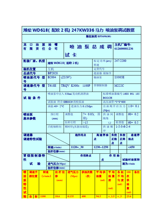
潍柴WD618 336马力
750
0.12
比800r/min(0.12Mpa)时拉杆行程小0.1mm以上
怠速
300
6.5
0
500
10
+_1
+_1
2
250
比300r/min时拉扞行程大0.9mm以上
起动
100
0
100
>18
+_3.5
+_3.5
18
1.预装尺吋:A.拉杆销孔中心至前壳端面距离L1=38.5(此尺吋不符由2项中尺吋调整保证). B.拉杆连接杆两销中心距L2=(L1+29)+_0.2.
C.浮动臂刃口至*8mm孔中心距L4=136(此尺吋调试中可进行调整) D.滑块中心至前壳端面距离L3=37.5+_0.1
E.限烟器滑块下端至限烟器下端面距离为20(此尺吋在调试中可进行调整). F.滑塞外圆面至后壳端面距离18+_0.1.
20气压时230---250r/min挂刀,起动掉刀.调整完毕,把调整垫片推到底对齐,把12个螺母再紧一遍.
(ml)
各缸不均匀度(ml)
100次供油量(ml)
备注
全
负
荷
标定点
1100
10.6
0.135
400
94.5
+_1.5
+_3
23.6
扭矩点
800
11.4
0.135
400
99
+_1
+_2.5
24.8
限烟点
500
10.8
0.045
400
90
+_2
+_2.5
社交焦虑:概念分析

社交焦虑:概念分析陈美雯,吴善玉*,郭泽英,刘 飞,王佳媛,许惠靖延边大学护理学院,吉林133002S o c i a l a n x i e t y d i s o r d e r :c o n c e p t u a l a n a l ys i s C H E N M e i w e n ,W US h a n y u ,G U OZ e y i n g ,L I UF e i ,W A N GJ i a y u a n ,X U H u i j i n gS c h o o l o fN u r s i n g ,Y a n b i a nU n i v e r s i t y,J i l i n 133002C h i n a C o r r e s p o n d i n g A u t h o r W US h a n y u ,E -m a i l :1357010343@q q.c o m A b s t r a c t O b je c t i v e :T o s y s t e m a t i c a l l y a n a l y z et h e d e v e l o p m e n ts t a t u s ,a p p l i c a t i o n ,d ef i n i ng a t t r i b u t e s ,c a s e s ,a n t e c e d e n t s ,a n d c o n s e q u e n c e s o f s o c i a l a n x i e t y th r o u g h li t e r a t u r e ,a n d t o c l a r i f y t h e c o n c e p t a n dc o n n o t a t i o no f s o c i a l a n x i e t y f r o mt h e p e r s p e c t i v e o f c o l l e g e s t u d e n t s i nC h i n a .M e t h o d s :B a s e do n W a l k e ra n d A v a n tc o n c e p ta n a l y s i s m e t h o d s ,c o n d u c tac o n c e p t u a la n a l ys i so fs o c i a l a n x i e t y .T h e p s y c h o l o g i c a l ,p h y s i o l o g i c a l ,a n d s o c i a l c h a r a c t e r i s t i c s o f s o c i a l a n x i e t y we r e d e s c r i b e d .R e s u l t s :B a s e d o n s e v e r a l d ef i n i t i o n s r e l a t e d t o s o c i a l a n x i e t y ,r e p e a t e d c h a r a c t e r i s t i c s o f s o c i a l a n x i e t y i n r e l e v a n t l i t e r a t u r e r e s e a r c h ,a n d t h eD S M -Ⅴd i a gn o s t i c c r i t e r i a f o r s o c i a l a n x i e t y ,t h e c h a r a c t e r i s t i c s o f t h e c o n c e p t o f s o c i a l a n x i e t y w e r e s u b j e c t i v e l y m a n i f e s t e d a s f e a r o f n e ga t i v e e v a l u a t i o n ;e x c e s s i v e f e a r o f o t h e r s s t a r i n g ;p h y s i o l o g i c a l r e a c t i o n s (m a n i f e s t e d a s r e d n e s s ,t r e mb l i n g ,a n d s w e a t i n g )oc c u r .C o n c l u s i o n :T h r o u gh W a l k e r a n d A v a n t 's c o n c e p t a n a l y s i sm e t h o d ,ac l e a r c o n c e p to f s o c i a l a n x i e t y w a so b t a i n e d .U n d e r s t a n d i n g th ec h a r a c t e r i s t i c s ,a n t e c e d e n t s ,a n d c o n s e q u e n c e s o f s o c i a l a n x i e t y c a nh e l p h e a l t h c a r e p r o f e s s i o n a l s r a i s e a w a r e n e s s ,b e t t e r i d e n t i f y s o c i a l a n x i e t y ,a n d p r o v i d en e c e s s a r y p s y c h o l o g i c a l s u p p o r t .T h e d e s c r i p t i o no f t y p i c a l c a s e s a n do p p o s i t e c a s e sh e l p s t ob e t t e r i d e n t i f y t h e c h a r a c t e r i s t i c so f s o c i a l a n x i e t y.T h e c o n c e p t a n a l y s i s o f s o c i a l a n x i e t y a i m s t oe f f e c t i v e l y c a r r y o u t p s y c h o l o g i c a l e d u c a t i o n ,i m p r o v e t h es o c i a l i n t e r a c t i o na b i l i t y of c o l l eg e s t u d e n t s ,h e l p m e di c a l s t a f f b e t t e r i d e n t i f y h i g h -r i s k g r o u p s ,a n de n h a n c e s o c i a l s u p p o r t f o r s o c i a l a n x i e t yg r o u ps .K e yw o r d s s o c i a l a n x i e t y d i s o r d e r ;s o c i a l p h o b i a ;s o c i a l a n x i e t y d i s o r d e r ;c o n c e p t a n a l y s i s ;c o l l e g e s t u d e n t s 摘要 目的:通过文献对社交焦虑的发展状况㊁应用㊁定义属性㊁案例㊁前因㊁后果等进行系统分析,从大学生的角度厘清我国社交焦虑的概念内涵㊂方法:依据W a l k e r 及A v a n t 概念分析法,进行社交焦虑的概念分析㊂对社交焦虑心理㊁生理㊁社会等方面的特点进行了描述㊂结果:根据几个与社交焦虑相关的定义㊁相关文献研究中重复出现的社交焦虑特点以及D S M -Ⅴ社交焦虑诊断标准,得出社交焦虑概念的特征是主观上表现为对负面评价的恐惧㊁过分害怕别人凝视㊁出现生理反应(表现为面色发红㊁颤抖㊁出汗)㊂结论:通过W a l k e r 及A v a n t 的概念分析法,得出了一个清晰的社交焦虑概念㊂理解社交焦虑的特征㊁前因及后果能够帮助医护人员提高认识,更好地识别社交焦虑,并提供必要的心理支持,典型案例的描述有助于更好地识别社交焦虑的特征㊂进行社交焦虑的概念分析,可有效开展心理教育,提高大学生的社会交往能力,帮助医护人员更好地识别高危人群,提高社交焦虑人群的社会支持㊂关键词 社交焦虑;社交恐惧症;社交焦虑障碍;概念分析;大学生d o i :10.12102/j.i s s n .2095-8668.2024.04.010 在‘ 健康中国2030 规划纲要“文件中指出,我国要促进心理卫生科普,加大对重点人群心理问题的预防和治疗[1]㊂随着每个人在社会活动中的压力日甚一日,社交焦虑的发病率也在逐年增高㊂社交焦虑(s o c i a l a n x i e t y di s o r d e r ,S A D )属于一种常见的焦虑,主要表现为个体对社交场合和他人交往的焦虑㊁恐惧㊁畏避等情绪与行为[2],目前,已成为仅次于重度抑郁和作者简介 陈美雯,硕士研究生*通讯作者 吴善玉,E -m a i l :1357010343@q q .c o m 引用信息 陈美雯,吴善玉,郭泽英,等.社交焦虑:概念分析[J ].循证护理,2024,10(4):632-635.酒精成瘾的第三大精神障碍[3]㊂国外的一项研究表明,社交焦虑属于一种常见的经历,近1/4的成年人在其一生中经历过至少一种重大的社会恐惧[4]㊂国外一直到20世纪80年代对社交焦虑进行了成体系的调查,包括社交焦虑的病因㊁影响因素㊁临床表现㊁结局指标㊁干预方法等㊂而国内至今对社交焦虑的研究仍旧进展迟缓,难形成完整系统,20世纪80年代,国内才开始对其进行研究,且多为影响因素及其干预研究方面,至今仍未形成具体定论和统一表述,并且用词杂乱,例如社交障碍㊁社交恐惧症㊁社会焦虑㊁恐人症㊁社交焦虑障碍等,混用或随意使用的情况,概念内涵的模糊不清影响了社交焦虑的护理㊂因此,有必要厘清社交焦虑的定义内涵,从而为后续开展健康心理卫生工㊃236㊃C H I N E S EE V I D E N C E -B A S E D N U R S I N GF e b r u a r y,2024V o l .10N o .4作提供概念支持㊂1方法使用 社交焦虑障碍 社交恐惧症 社交障碍 s o c i a la n x i e t y d i s o r d e r s o c i a l p h o b i a h u m a n c o mm u n i c a t i o nd i s o r d e r s 等作为关键词,检索中国知网㊁万方数据库㊁维普数据库㊁P u b M e d㊁E M b a s e等,检索时限为自建库至2022年8月24日㊂纳入涉及社交焦虑概念的定义性特征㊁前因㊁后果等内容的文献,排除重复㊁会议㊁不相关的文献,最终保留20篇英文和10篇中文文献㊂本研究选用W a l k e r和A v a n t概念分析法[5],包括选择1个概念㊁确定概念分析目的㊁找到相关概念㊁确定定义性特征并给出定义㊁举出1个典型案例㊁确定前因后果6个步骤㊂2结果与分析2.1社交焦虑的由来及变迁社交焦虑最早可以回溯到1846年,C a s p e r提出了赤面恐怖,俗称 红脸病 ,表现为与陌生人异性说话交往时会脸红,从此拉开了社交焦虑研究的序幕㊂1966年,英国精神病学家M a r k和G e l d e r将社交焦虑定义为一种对他人的审视或评价的夸大恐惧这也是社交焦虑一词第一次被明确提出[5]㊂起初,有很多学者对其饶有兴趣,但是由于社交焦虑的临床表现与内向㊁回避型人格障碍难以区分,所以研究始终踏步不前㊂1980年,B u s s将社交焦虑定义为:个体在与他人交往的过程中,由于对自我的消极评价而引起的恐惧害怕的情绪体验[6]㊂在‘国际疾病分类“第10版[7]和‘精神疾病诊断和统计手册“第4版[8]对社交焦虑障碍的标准定义是:对一个或多个可能发生尴尬的社交场合的持续恐惧,这种恐惧或焦虑与由个人的文化规范所决定的社交场合所构成的实际威胁不成比例㊂可以看出,社交焦虑病人在与他人交往时表现出过度恐惧,并且会认为外界对自己的表现呈负面评价,因此,他们会试图避免参加社交场景,以此来逃避外界的负面评价㊂在国内,由于对此疾病缺少足够的认识,常常将社交焦虑与内向㊁害羞㊁懦弱等性格问题相混淆,同时也鲜有病人主动寻求专业医师的治疗,因此,无法引起足够重视㊂随着心理健康卫生相关知识的科普,病人逐渐认识到自己的问题并到心理门诊寻求帮助,希望个人得到充分的发展[9],此时国内学者及相关机构开展研究便应时而生㊂在国内,不少研究者从自己的角度出发,对社交焦虑给予了更为准确的定义㊂2000年郭晓薇[10]将其解释为个体面对社会关系时强烈的慌张㊁惧怕的情绪,并产生逃避行为㊂2001年彭纯子[11]认为社交焦虑是指个体在现实的或幻象的社交情景中,由于过于敏锐,担心他人对自己做出负性评价,从而发生不同梯度的焦躁情绪,且伴有回避行为㊂在其对社交环境的描述中,提出了病人会假设存在一个社交情景,从而肯定了认知偏差的存在㊂2006年张瑾[12]则认为社交焦虑是指个体在社交情景中的一种不利的情绪体验㊂总之,社交焦虑是个体在他人面前表现时所产生的消极情绪,在不同的人际关系交往中,会持续产生不安的消极情绪并伴随着脸红发热等生理反应,甚至为了避免这种场景出现而对社交场合产生回避行为㊂2.2社交焦虑的定义属性通过上述回顾与分析,从中国精神疾病诊断标准㊁‘精神疾病诊断与统计手册Ⅴ“(D S M-Ⅴ)[13]诊断标准及社交焦虑相关研究共总结出社交焦虑的3个特性可分为主观和客观两种,主观上表现为对负面评价的恐惧;过分害怕别人凝视;客观上表现为面色发红㊁颤抖㊁出汗㊂2.2.1害怕他人的负面评价害怕他人的负面评价是社交焦虑的关键特征㊂最新的D S M-Ⅴ对于社交焦虑的诊断标准中指出[8]: 个体害怕他或她的行为方式或表现出会被负面评价的焦虑症状 ,其也将此作为主要恐惧列入了社交焦虑诊断的标准A[13]㊂A s h e r等[14]也指出,社交焦虑病人害怕他们会以一种尴尬的方式行事,并可能会导致收到其他人的负面评价㊂2.2.2过分害怕别人凝视在中国精神障碍分类与诊断标准(第3版) (C C M D-3)对社交焦虑的评判标准中指出了病人的畏惧对象主要是社交情境和人际交流,如在公共场所与人沟通㊁与他人目光对视等㊂在李波等[15]对其的定义中,也强调了社交焦虑病人对于他人凝视而产生的强烈焦虑,因此,极力逃避社交场合的特点㊂社交焦虑病人如果处于无法回避的社交场合中,则会出现第3个定义性特征 生理反应,比如脸红㊁战栗㊁尿急㊁口吃㊁大汗淋漓等㊂2.2.3生理反应在生理反应中,脸红更是典型的社交焦虑特征㊂而其他的生理反应还包括出汗㊁发抖㊁口吃等,这些身体反应都有一个共同点,那就是别人可以观察到,而不容易控制㊂在日本的研究中,社交焦虑病人害怕自己脸红是最常见的恐惧,其次是害怕感觉紧张[16]㊂国内学者杨相宜[17]也在研究中指出,社交焦虑的特点之一即人际交往场合会使社交焦虑个体产生脸红㊁心搏加速㊁出汗等自主神经紊乱的生理症状㊂2.3典型案例㊃336㊃循证护理2024年2月第10卷第4期(总第120期)小白是1名即将毕业的学生,目前正处于寻找工作的时期,但是他却无法直视面试官投出一份简历,他说: 每次到了招聘会现场,我都无法抬头走向招聘人员的隔间,我害怕他们看到我没有任何亮点的简历,害怕他们对我4年的大学生活给予否定,我一想到这个场景就会浑身发抖㊁脸红㊁心跳加速,更加无法迈向招聘人员说出一句 您好,请您看看我的简历 ㊂同时我也害怕做心理咨询,也害怕和别人说,大学4年,就是这样熬过去的 ㊂2.4前因后果2.4.1前因2.4.1.1个人因素个人层面上的影响对社交焦虑的形成也有很大的意义㊂在人格方面,根据F a h l e n的研究,88%的社交焦虑病人都有着不同程度的人格弱点,表现为内向㊁胆怯㊁易紧张㊁自我否定等㊂但国内学者刘杉文等[18]存在不同观点,他认为不能只从内向㊁外向来评判一个人以后是否会产生社交焦虑,这并不是评定一个人心理健康的唯一标尺,对于外向的人应该多注重其心底的实际想法,对于内向的人则应该多重视其自身潜在的长处㊂2.4.1.2同伴因素近年来研究发现,同伴伤害使儿童和青少年有发展社会焦虑的风险[19-20]㊂一个受到同伴伤害的孩子更有可能经历有害的社会互动,这可能会加强对自己和同伴关系的负面信念,导致回避社交互动,从而增加社交焦虑水平[21-22]㊂研究证明,患有社交焦虑的青少年同时也更容易成为同伴伤害的目标[23]㊂2.4.1.3家庭因素家庭因素也对社交焦虑的发生起着显著的影响㊂包括家庭教养方式㊁家庭环境童年虐待及创伤等㊂李秀丽等[24]对初中生进行调查,结果发现父亲的过度保护会对初中生的社交焦虑产生影响㊂此结论与张翔等[25]的研究结果相符,其认为社交焦虑与父母的严厉惩罚㊁过分干涉㊁过度保护呈正相关,而与父亲情感温暖呈负相关㊂有研究采用童年虐待和创伤量表对成人进行问卷调查,结果发现童年经历过频繁虐待㊁有过创伤经历和情感体验与成年后社交焦虑的发生有相关性[26]㊂2.4.2后果2.4.2.1对学生一项新西兰长达21年的纵向研究结果显示,患有社交焦虑和其他不利的心理健康与生命历程的许多结局相关,这其中包括尼古丁㊁酒精㊁非药物依赖㊁自杀行为㊁教育质量不达标等,社交焦虑对于大学生的学业失败㊁考试失败风险增加和毕业失败具有影响[27]㊂有研究强调,患有社交焦虑的学生幸福感会更低,在学业上会产生许多问题,例如辍学㊁考试失败等[28]㊂2.4.2.2对成人在2000年针对整个欧洲的社交焦虑流行病学调查结果显示,患有社交焦虑症的个体具有明显的功能障碍,特别是在社交关系的发起和维持以及教育㊁工作成就等方面[29]㊂而在经济方面则表现为工作效率会大幅下降,增加失业的风险㊂2004年一项欧洲精神疾病流行病学项目的结果显示,包括社交焦虑在内的精神障碍是工作角色残疾和生活质量的重要决定因素,往往超过常见慢性身体障碍的影响[30]㊂W i t t c h e n 等[28]针对社交焦虑的对照试验结果显示,病人会由于社交焦虑问题而导致工作中失误率上升,工作绩效下降㊂3小结综上所述,国外对于社交焦虑的研究成熟又系统,从诊断标准到前因后果都比国内的研究领先几十年,而又由于东西方文化的文化背景不同,对于社交焦虑研究的流行病学㊁影响因素等产生了部分分歧㊂2010年以来,我国学者开始了对社交焦虑前所未有的关注,通过了解我国社交焦虑的流行现状,确定与其形成和发展的相关因素,进一步探索疾病的发生㊁生理与心理发生机制,为疾病预防提供有益的参考㊂参考文献:[1]尤小芳,施姣姣,谭晖,等.健康中国建设背景下研究生心理健康教育的若干思考[J].教育生物学杂志,2020,8(3):193-197. [2] MA G E E WJ.A g o r a p h o b i a,s i m p l e p h o b i a,a n d s o c i a l p h o b i a i n t h en a t i o n a l c o m o r b i d i t y s u r v e y[J].A r c h i v e so fG e n e r a lP s y c h i a t r y, 1996,53(2):159-168.[3] J U PJ,Z HU C,C H E N G Y.D e l e t i o no fe p h r i n-B2f r o m G A Tn e u r o n s i n m o u s ec a u s e ss o c i a l a n x i e t y d i s o r d e r l i k e p h e n o t y p e s[J].C h i n e s eJ o u r n a lo fP h a r m a c o l o g y a n d T o x i c o l o g y,2018,32(9):730-732.[4] R U S C I O A M,B R OWN T A,C H I U W T,e ta l.S o c i a l f e a r sa n ds o c i a l p h o b i a i nt h eU S A:r e s u l t s f r o mt h eN a t i o n a lC o m o r b i d i t y S u r v e y R e p l i c a t i o n[J].P s y c h o l o g i c a lM e d i c i n e,2008,38(1):15-28.[5]WA L K E R O.S t r a t e g i e s f o r t h e o r y c o n s t r u c t i o ni nn u r s i n g[J].P e a r s o nS c h w e i zA g,2010,44(44):434-436.[6] MA R K S IM,G E L D E R M G.D i f f e r e n t a g e s o f o n s e t i n v a r i e t i e s o fp h o b i a[J].A m e r i c a n J o u r n a l o f P s y c h i a t r y,1966,123(2):218-221.[7]W o r l d H e a l t h O r g a n i z a t i o n.I n t e r n a t i o n a ls t a t i s t i c a l c l a s s i f i c a t i o no fd i s e a s e s a n d r e l a t e d h e a l t h p r o b l e m s,10t h r e v i s i o n[R].G e n e v a:W o r l dH e a l t hO r g a n i z a t i o n,1992:1.[8] A m e r i c a n P s y c h i a t r i c A s s o c i a t i o n.D i a g n o s t i c a n d s t a t i s t i c a l㊃436㊃C H I N E S EE V I D E N C E-B A S E D N U R S I N GF e b r u a r y,2024V o l.10N o.4m a n u a l o f m e n t a ld i s o r d e r s,4t he d i t i o n(D S M-Ⅳ)[R].[s.l.]:A m e r i c a nP s y c h i a t r i cA s s o c i a t i o n,1994:1[9] A m e r i c a n P s y c h i a t r i c A s s o c i a t i o n.D i a g n o s t i c a n d s t a t i s t i c a lm a n u a l o fm e n t a ld i s o r d e r s:t e x tr e v i s i o n[J].R e v i s e d,2010,189(1):39-44.[10]郭晓薇.大学生社交焦虑成因的研究[J].心理学探新,2000,20(1):55-58.[11]彭纯子.大学生社交焦虑的团体干预的实验研究[D].长沙:湖南师范大学,2001.[12]张瑾.大学生社交焦虑的团体辅导实验研究[D].苏州:苏州大学,2006.[13] BÖG E L SS M,A L D E N L,B E I D E L D C,e ta l.S o c i a la n x i e t yd i s o r de r:q u e s t i o n s a n da n s w e r sf o r t h eD S M-Ⅴ[J].D e p r e s s i o na n dA n x i e t y,2010,27(2):168-189.[14] A S H E R M,A S N A A N IA,A D E R K AIM.G e n d e rd i f f e r e n c e s i ns o c i a l a n x i e t y d i s o r d e r:a r e v i e w[J].C l i n i c a l P s y c h o l o g y R e v i e w, 2017,56:1-12.[15]李波,钱铭怡,马长燕.大学生羞耻感对社交焦虑影响的纵向研究[J].中国临床心理学杂志,2005,13(2):156-158. [16] MA T S U N A G A H,K I R I I K E N,MA T S U I T,e t a l.T a i j i nk y o f u s h o:af o r m o fs o c i a la n x i e t y d i s o r d e rt h a tr e s p o n d st os e r o t o n i n r e u p t a k e i n h i b i t o r s[J].I n t e r n a t i o n a l J o u r n a l o fN e u r o p s y c h o p h a r m a c o l o g y,2001,4(3):231-237.[17]杨相宜.大学生生活事件㊁认知情绪调节与社交焦虑的关系研究[D].兰州:西北师范大学,2014.[18]刘杉文,张云朋,叶存春.大学生人格类型与社交焦虑关系的研究[J].心理月刊,2020(20):68-69.[19] T I L L F O R SM.W h y d o s o m e i n d i v i d u a l s d e v e l o p s o c i a l p h o b i a?Ar e v i e w w i t h e m p h a s i s o n t h e n e u r o b i o l o g i c a li n f l u e n c e s[J].N o r d i c J o u r n a l o f P s y c h i a t r y,2004,58(4):267-276. [20]S I E G E L R S,L A G R E C A A M,HA R R I S O N H M.P e e rv i c t i m i z a t i o na n ds o c i a la n x i e t y i na d o l e s c e n t s:p r o s p e c t i v ea n dr e c i p r o c a l r e l a t i o n s h i p s[J].J o u r n a lo fY o u t ha n d A d o l e s c e n c e, 2009,38(8):1096-1109.[21] L O U K A SA,P A S C H K E.D o e s s c h o o l c o n n e c t e d n e s sb u f f e r t h ei m p a c to f p e e rv i c t i m i z a t i o n o n e a r l y a d o l e s c e n t s's u b s e q u e n ta d j u s t m e n t p r ob l e m s?[J].T h eJ o u r n a lo fE a r l y A d o l e sc e n c e,2013,33(2):245-266.[22] R A N T A K,K A L T I A L A-H E I N O R,F RÖJ D S,e t a l.P e e rv i c t i m i z a t i o n a n d s o c i a l p h o b i a:a f o l l o w-u p s t u d y a m o n ga d o l e s c e n t s[J].S o c i a lP s y c h i a t r y a n dP s y c h i a t r i cE p i d e m i o l o g y,2013,48(4):533-544.[23]S P E N C E S H,R A P E E R M.T h e e t i o l o g y o fs o c i a la n x i e t yd i s o r de r:a ne v i d e n c e-b a s e d m o d e l[J].B e h a v i o u r R e s e a r c ha n dT h e r a p y,2016,86:50-67.[24]李秀丽,王美芳.父母教养方式与城乡初中生社交焦虑的关系[J].青少年研究(山东省团校学报),2015(2):9-13. [25]张翔,王娟,陈良辉,等.城市流动儿童孤独及社交焦虑与人格特征及父母教养方式关系[J].中国儿童保健杂志,2014,22(6): 576-579.[26]曾玲芸,肖融,张伟.社交焦虑障碍患者父母的人格特征和心理健康状况调查[J].精神医学杂志,2007,20(6):346-347. [27] WO O DWA R DLJ,F E R G U S S O N D M.L i f e c o u r s eo u t c o m e so fy o u n gp e o p l ew i t ha n x i e t y d i s o r d e r s i na d o l e s c e n c e[J].J o u r n a l o f t h eA m e r i c a nA c a d e m y o f C h i l d&A d o l e s c e n t P s y c h i a t r y,2001, 40(9):1086-1093.[28] W I T T C H E N H U,F U E T S C H M,S O N N T A G H,e t a l.D i s a b i l i t y a n d q u a l i t y o f l i f e i n p u r ea n dc o m o r b i ds o c i a l p h o b i a.F i n d i n g s f r o ma c o n t r o l l e d s t u d y[J].E u r o p e P s y c h i a t r y,2000,15(1):46-58.[29] A L O N S O J,A N G E R M E Y E R M C,B E R N E R T S,e t a l.D i s a b i l i t y a n d q u a l i t y o fl i f ei m p a c t o f m e n t a l d i s o r d e r si nE u r o p e:r e s u l t s f r o mt h eE u r o p e a nS t u d y o f t h eE p i d e m i o l o g y o fM e n t a l D i s o r d e r s(E S E M e D)p r o j e c t[J].A c t a P s y c h i a t r i c aS c a n d i n a v i c a,2004,109(s420):38-46.[30] L E C R U B I E R Y,W I T T C H E N H U,F A R A V E L L IC,e ta l.AE u r o p e a n p e r s p e c t i v eo ns o c i a la n x i e t y d i s o r d e r[J].E u r o p e a nP s y c h i a t r y,2000,15(1):5-16.(收稿日期:2022-09-27;修回日期:2023-11-28)(本文编辑孙玉梅)㊃536㊃循证护理2024年2月第10卷第4期(总第120期)。
A conceptual model completely independent
A conceptual model completely independentof the implementation paradigmOscar Diestea,*,Marcela Genero b,1,Natalia Juristoc,2,Jos e L.Mat ec,2,Ana M.Moreno c,2aDepartamento de Electr onica y Sistemas,Escuela Polit e cnica Superior,Universidad Alfonso X el Sabio,28691-Villanueva de la Ca ~n ada,Madrid,SpainbDepartamento de Informatica,Escuela Superior de Informatica,Universidad de Castilla-La Mancha,Paseo de la Universidad,4,13071Ciudad Real,SpaincDepartamento de Lenguajes y Sistemas,Inform a ticos e Ingenier ıa del Software,Facultad de Inform a tica,Universidad Polit e cnica de Madrid,28660-Boadilla del Monte,Madrid,SpainReceived 23December 2002;accepted 27December 2002AbstractSeveral authors have pointed out that current conceptual models have two main shortcomings.First,they are clearly oriented to a specific development paradigm (structured,objects,etc.).Second,once the conceptual models have been obtained,it is really difficult to switch to another development paradigm,because the model orientation to a specific development approach.This fact induces problems during development,since practitioners are encouraged to think in terms of a solution before the problem at hand is well understood,thus anticipating perhaps bad design decisions.An appropriate analysis task requires models that are independent of any implementation issues.In concrete,models should support developers to understand the problem and its constraints before any solution is identified.This paper proposes such an alternative approach to conceptual modelling,called ‘‘problem-oriented analysis method’’.Ó2003Elsevier Inc.All rights reserved.Keywords:Conceptual modelling;Generic conceptual model;Development orientation1.IntroductionRequirements engineering (RE)activity is composed by four iterative tasks:elicitation,analysis,documen-tation and validation (SWEBOK,2000).Of these tasks,analysis is one of the most critical,due to the huge im-portance of its goals:(1)understand the problem to be solved;(2)develop conceptual models (CMs),which represent the problem understanding;and (3)define the features of an implementation-independent solution tothe problem in question,that is,identify the require-ments to be satisfied by the future software system.CMs play a central role during analysis,since they make possible to•make real-world concepts and relationships tangible (Motschnig-Pitrik,1993);•record parts of reality that are important for per-forming the task in question and downgrade other el-ements that are insignificant (Borgida,1991);•support communication among the various ‘‘stake-holders’’(customers,users,developers,testers,etc.)(Mylopoulos et al.,1997);•detect missing information,errors or misinterpreta-tions,before going ahead with system construction (Schreiber et al.,1999).Conceptual modelling is gaining in importance as software systems become more complex and the problem*Corresponding author.Present address:Departamento de Sist-emas Informaticos y Programacion,Facultad de Informatica,Uni-versidad Complutense de Madrid,Ciudad Universitaria S/N,28040Madrid,Spain.Tel.:+34-91-394-75-46.E-mail addresses:odiestet@fdi.ucm.es (O.Dieste),marcela.gen-ero@uclm.es (M.Genero),natalia@fi.upm.es (N.Juristo),jlmate@fi.upm.es (J.L.Mat e ),ammoreno@fi.upm.es (A.M.Moreno).1Tel.:+34-926-29-54-85x3740.2Tel.:+34-91-336-6922/6921/6929.0164-1212/$-see front matter Ó2003Elsevier Inc.All rights reserved.doi:10.1016/S0164-1212(03)00061-XThe Journal of Systems and Software 68(2003)183–198/locate/jssdomain moves further away from knowledge familiar to developers.In complex domains,to understand the user need becomes more difficult and,therefore,conceptual modelling grows to be crucial.Several researchers claim that proper conceptual modelling is crucial since it helps to represent the problem to be solved in the user domain(McGregor and Korson,1990;Bon-fatti and Monari,1994;Høydalsvik and Sindre, 1993).Nevertheless,several authors have argued that the CMs used nowadays are oriented to specific software development approaches.This orientation has two re-percussions:(1)CMs have computational constraints, that is,CMs developers represent specific implementa-tion characteristics in the domain models(Bonfatti and Monari,1994;Høydalsvik and Sindre,1993;McGinnes, 1992);(2)CMs prescribe the subsequent development process,in which the CMs are more or less directly transformed into design models(Henderson-Sellers and Edwards,1990;Davis,1993;Jalote,1997;Northrop, 1997;Juristo and Moreno,2000),and their trans-formation to a design model related to another de-velopment paradigm is exceedingly complicated and sometimes impossible.This means that the CMs used nowadays are not appropriate for analysis.In this paper,we propose an alternative approach that aims to remove the above constraints.The paper is structured as follows:Section2 discusses the problems with using CMs identified by several researchers,and establish the requirements for an appropriate CM.Sections3and4describe our ap-proach for a conceptual modelling process independent of any development paradigm.Finally,the preliminary results of applying our approach are discussed in Sec-tion5.2.The computational orientation of conceptual modelsThe term CM originally emerged in the database field.CMs were used to represent the data and relations that were to be managed by an information system,ir-respective of any implementation feature.Nevertheless, CMs are used for more than is acknowledged in data-bases.CMs are used in RE to•encourage the analyst to think and document in terms of the problem,as opposed to the solution (Davis,1993);•describe the universe of discourse in the language and in the way of thinking of the domain experts and users(Beringer,1994);•formally define aspects of the physical and social world around us for the purposes of understanding and communication(Loucopoulos and Karakostas, 1995);•help requirements engineers understand the domain (Kaindl,1999).Taking into account the above definitions,the main characteristics of any CM can be said to be description and understanding.That is,CMs should be used by de-velopers to•understand the user needs;•reach agreement with users on the scope of the system and how it is to be built;•use the information represented in the model as a ba-sis for building a software system to meet user needs.Several authors have pointed out that current CMs sometimes fail to do their jobs of description and un-derstanding during analysis.Criticisms can be divided into two major groups:•The orientation of the conceptualisation methods, stressing the fact that most CMs are oriented to get-ting a computational solution to the problem or need raised and not to easing the understanding of the user need.For instance,regarding to object orientation: It is argued that object-oriented methods are a ÔnaturalÕrepresentation of the world.Nevertheless, this idea is a dangerous over-simplification (McGinnes,1992).Object-oriented analysis has several shortcomings, most importantly in being target oriented ratherthan problem oriented(Høydalsvik and Sindre,1993).Object-oriented analysis techniques are strongly affected by implementative issues(Bonfatti and Monari,1994).Thus,for example,dataflow diagrams(DFD)are clearly guided by functions,the key components of structured software,and,likewise,the models used in object-oriented analysis lead directly to software de-veloped by means of classes,objects,messages, polymorphism,etc.,the basic concepts of object-ori-ented software.•The association between CMs and specific ap-proaches to software development.Here,the use ofa given CM during early phases of the developmentlimits the number of possible implementation alterna-tives and means that only the options that are com-patible with the CM used originally are feasible.If computational characteristics are included in CMs,these are linked to a particular implementation approach,that is,once a given conceptualisation method has been selected to describe the problem do-main,it is practically impossible to change the above method a posteriori without having to reanalyse the problem.This has also been stressed by several re-searchers:184O.Dieste et al./The Journal of Systems and Software68(2003)183–198Because of a poorly understood overlap among different requirements languages,it is difficult tochange languages mid-project(Davis et al.,1997).The use of a CM during analysis defines nearly univocally how the design shall be done(Hender-son-Sellers and Edwards,1990).Perhaps the most difficult aspect of problem anal-ysis is avoiding software design(Davis,1993).It is sometimes mistakenly believed that the struc-tures produced during analysis will and should becarried through in design(Jalote,1997).The boundaries between analysis and design activ-ities in the object-oriented model are fuzzy(Nor-throp,1997).The CM used preconditions the software system development approach(Juristo and Moreno, 2000).Owing to this limitation,if dataflow diagrams have been used to model the problem domain,for example,it will almost certainly be necessary to use the structured method in later development phases;whereas a method of object-oriented development will have to be used following upon an object-oriented analysis.Therefore,if we intended to switch development paradigms,that is, for example,pass from a dataflow diagram to an object-oriented design,this transformation would lead to an information gap that is very difficult tofill.This occurs because each CM acts like a pair of glasses used by the developer to observe the domain and user reality.These glasses highlight certain features,tone down others and hide others.Once the real world has beenfiltered through the CM,it is difficult to retrieve anything that has been lost or condensed,even if the later development process requires this information.The only way of recovering the features lost in the CMfilter is to reanalyse reality using a different pair of glasses;that is,to repeat the operation using another CM.Authors like Coleman et al.(1994), Champeaux et al.(1993)or Wieringa(1991)have already discussed this situation,addressing the incompatibility between the CMs used in the structured approach and object-oriented CMs,owing to the conceptual difference between the elements used in both approaches.In short,the software system development approach can be said to be preconditioned from the very start,as soon as the CMs are built.The problem with including computational considerations within the CM is that developers are forced to make a solution-oriented deci-sion during the early development phases,when the problem to be solved is still not well enough understood. This means making design decisions when not all the information relevant to the problem is known.Devel-opers thus run the risk of making the wrong decision, because they are not in possession of all the information. Excepting trivial problems,this precondition implies that the development approach is chosen before the user need has been understood,which is the job of concep-tual modelling.Even worse,very often the CMs selected are models with which developers are familiar,models called for by individual standards or even,as specified by Mylopoulos et al.(1999),the models that are‘‘in fashion’’.So,in the era when the structured approach was in vogue,techniques such as DFDs were used for conceptual modelling,whereas,today,with the rise of object-oriented programming and design,techniques like object diagrams,interaction diagrams,etc.,are employed for problem analysis.In order to avoid the commented problems of current CMs,they should include all the information required about the problem for developers to later address the software system that is to solve the user problem.In-deed,it is needed that conceptualisation methods meet the following:•Understanding the need raised by the user before considering an approach for developing a software system that meets this need.•The understanding of the need must be independent of the chosen problem-solving approach,that is,it must not precondition the use of any development approach.•Having criteria for deciding which is the best develop-ment approach once the user need has been under-stood.These criteria can only be met by redefining the conceptual modelling process as it is now carried out in the RE analysis task.3.An implementation-paradigm independent conceptual modelThe proposed approach,called‘‘problem-oriented analysis method’’(POAM),tries to meet the above-mentioned criteria,and is characterised by(1)using representation diagrams,which we call generic concep-tual models(GCMs),that do not presuppose any im-plementation paradigm;(2)defining a detailed analysis process;and(3)deriving,from the GCM,the best-suited CM(that is,a CM now used in RE,like DFD,use cases, etc.)to continue with development according to the methods used nowadays.The following sections present the main components of the proposed approach,that is, the GCM,which is described in Section3.1,and the POAM process,which is discussed in Section3.2.3.1.Generic conceptual modelThe CMs currently used in software engineering have to be used exclusively,that is,mostly rule out the use ofO.Dieste et al./The Journal of Systems and Software68(2003)183–198185a complementary CM.In some cases,when using a DFD,for example,the use of supplementary notations, such as process specifications or even the entity/rela-tionship model,is permitted,although these are sub-ordinated to the process diagram set out in the DFD.The GCM proposed in this approach is based on complementariness.Instead of using a representation schema that dominates the modelling process,three complementary representation schemas are -plementary means:(1)each schema supports the others, satisfactorily recording information they do not repre-sent and(2)the information in one schema can migrate, that is,move from one schema to another without the GCM losing information.Complementariness is important because the way the information is expressed benefits or impairs its under-standing(Vessey,1991).The different components of the GCM can represent the same information,expressing it either as a graph,table or text.This means that each analysis process participant can select and use the best-suited expression,either on the basis of previous expe-rience or in accordance with current needs.The proposed GCM components are as follows:•Element maps:Information representation structures belonging to a given knowledge domain or problem.Element maps are variations on the conceptual maps, derived from the work of Ausubel on Learning The-ory and Psychology,later formalised by Novak andG owin(1984).We use the termÔelement mapsÕin-stead ofÔconcepts mapsÕ,becauseÔconceptÕis a over-loaded word in SE.For example,ÔconceptÕis often used to meanÔdataÕ.When we useÔelementÕ,we are talking aboutÔstatic conceptsÕ,like data,rules or facts,but also aboutÔdynamic conceptsÕ,like pro-cesses,events,and so on.Conceptual maps(as employed in psychology)can be used to express and graphically represent concepts and associations between concepts as a hierarchical struc-ture.Element maps differ from conceptual maps used in Psychology on three essential points:(1)they are gen-erally structured as a complex graph and not necessarily hierarchically;(2)both the concepts(elements in our approach)and the associations,which represent estab-lished knowledge in conceptual maps,are likely to evolve over time as the analysis progress and(3)some special concepts(elements in our approach)and asso-ciations have been defined to restrict the spectrum of possible readings of the elements map for the purpose of raising the efficiency of POAM application.•Dictionaries:Tabulated information representation schemas.Dictionaries have a set of predefinedfields that define what sort of information they record.There are two main types of dictionaries:Identificative dictionary(or glossary):This dictio-nary merely records the information required torecognise a element or association appearing whileinvestigating the problem and to distinguish oneelement or association from another.Descriptive dictionary:Its goal is to record negoti-ated information about elements and associations,that is,information that all the participants in the analysis process agree to be true.This information is,additionally,practically complete,that is,all the important aspects of the problem and its solution will have been identified and recorded if this dictio-nary has been correctly built.•Narrative description:Natural language text that describes the information recorded in the elements map and the dictionaries.The narrative description can be automatically derived from the elements map and dictionaries(although the result is not a literary masterpiece),which has some clear benefits for model validation.The text is very understandable for end users and,as there is a bijective relationship between the narrative description and the other representation schemas,the comments and corrections made by the users can be fed back into those schemas.The three above-mentioned representation schemas are used during the POAM process activities and steps. The POAM process is described below.3.2.Generic conceptual model development processThere are two points of inflection during analysis, each determined by its goals,that is:(1)move from ig-norance to an understanding of the problem to be solved,which should be reflected in the creation of CMs, and(2)go from an understanding of the problem to a solution characterization,which moves from a very abstract level in the early stages of analysis(some re-strictions,characteristics,etc.,of the future software system)to a more concrete formulation as the devel-operÕs knowledge about the problem increases(a list of the desired software system features).Therefore,the proposed process is composed of two activities,as shown in Fig.1(a).The two activities differentiate two states in analysis:a problem-oriented state and a solu-tion-oriented state.The goal of thefirst activity,called problem-oriented analysis,is to understand the problem to be solved and ends when the GCM,which represents the acquired knowledge,has been developed.This G CM is the input for the second activity,called software-oriented analysis, whose goal is to identify which typically used CM is best suited for representing the problem,as well as to transform the GCM into the above-mentioned CM.Thisfirst level of decomposition is too general to guide a developer as to how to perform analysis. Therefore,both activities are divided into two steps,as shown in Fig.1(b),which are further broken down into186O.Dieste et al./The Journal of Systems and Software68(2003)183–198detailed tasks.Thus,problem-oriented analysis is de-composed into the following steps:•Preliminary analysis:In this step,the problem is ex-amined superficially with the aim of defining a prelim-inary model.The goals of this step are to(1)identify the most important elements of the problem domain;(2)describe these elements;and(3)organise all theelements of the problem domain into a structure, by means of which to define the associations there are among these elements.•Comprehensive analysis:In this step,the problem is studied in as much detail as required to develop the comprehensive model,that is,the complete GCM.The goals of this step are to(1)check that the impor-tant problem elements have been identified;(2)de-scribe the above elements exhaustively and(3) clearly determine the associations among elements.In the above paragraphs,we introduced the concepts of preliminary and comprehensive models.The prelimi-nary model is a simplified version of the GCM,obtained after the preliminary analysis,which is composed of(1)a elements map––usually hierarchical and not generally a graph,(2)identificative dictionary and(3),narrative descriptions.The comprehensive model,that is,the complete GCM output at the end of the comprehensive analysis,differs from the preliminary model in that(1) the elements map is more detailed and is generally a graph,(2)the descriptive dictionary is used instead of the identificative dictionary and(3)the narrative de-scription is optional and is usually excluded.Having completed the problem-oriented analysis,we will get an exhaustive description of all the important problem elements and of the spectrum of associations between these elements.This information,contained in the GCM,is of intrinsic value,as it helps developers and other participants in analysis to understand the prob-lem,which is one of the key objectives of analysis.Using the proposed approach,however,we can go even further to derive,from the information contained in the GCM,a CM by means of which to continue software system development using any of the develop-ment approaches now available,such as structured, object-oriented or real-time approaches.That CM is derived in the software-oriented analysis activity.This activity is decomposed into two steps.Identification of the suitable conceptual model:In this step,we identify the suitable conceptual model (SCM).The SCM is the target CM that can represent all the information gathered in the GCM for a given problem more fully.An interpretation procedure has to be applied to the G CM to identify the SCM.The interpretationO.Dieste et al./The Journal of Systems and Software68(2003)183–198187procedure can be used to rewrite the GCM from a computational viewpoint,that is,to assign builders used by the classical CMs to the constituent elements of the GCM,which in turn form the building blocks of com-puter systems.We have used a requirements representation formal-ism proposed by Davis et al.(1997)for rewriting pur-poses,although it has been profoundly modified for use with the G CM.This formalism,termed‘‘canonical model’’,in accordance with its authorÕs intent,provides a set of building blocks that can be used to represent the information contained in a range of CMs.This means that it can be used as a lingua franca,which averts,as explained below,having to deal with each CM sepa-rately.The interpretation procedure,therefore,involves as-signing a computational interpretation to each of the building blocks of the GCM or,in other words,as-signing each GCM element to one of the canonical model elements.This assignation will be totally formalised and engi-neer independent,unless any ambiguities arise in the assignation.Ambiguity is the possibility of assigning two or more elements of the canonical model to any given G CM element.In this case,it is the engineer who has to decide,depending on the semantics of the GCM and the canonical model,which particular interpretation is the best suited.After interpretation,the GCM is called the require-ments canonical model(RCM),as the GCM can now be read in computational terms,as a description of what should be future software system operation.After out-putting the RCM,we can determine the SCM.The SCM will be the CM that is capable of repre-senting most RCM propositions.We have defined a measure,calledfitness,to give a quantitative value of suitability.Fitness is defined as the ratio between the propositions a given CM can represent and the total number of RCM propositions.Accordingly,the SCM is the CM with the highestfitness value.Additionally,this measure provides supplementary information,namely,the extent to which the SCM is suitable.For example,a CM may be suitable(that is,be the best of all the models)and still very partially rep-resent the information gathered about the problem do-main(in this case,lowfitness values would be obtained). Additionally,it can even establish what difference,in terms of representation capability,there is between two particular CMs(which would be the difference between the respectivefitness values).Derivation of the selected conceptual model:In this step,the RCM is translated into the target CM.We use a derivation procedure to generate the target CM.The derivation procedure basically involves using a set of derivation tables and rules.There are as many tables as there are possible target CMs.Each derivation table contains all the possible combinations of canonical model elements that can be expressed in a given target CM,along with the expression of this combination in the particular format used by the CM in question (graphs,text,tables,etc.).As each GCM element has been labelled in the RCM and we have calculated thefitness of the different CMs, we can now refer to the appropriate derivation table and use it to directly generate fragments of the target CM. These fragments can later be assembled,unambigu-ously,tofinally output the correct target CM.The derivation rules modulate the use of each deri-vation table,altering the RCM in a controlled manner, so that the target CMfinally obtained resembles as closely as possible a target CM developed independently for the same problem.The target CM obtained in the above step can be refined by entering more information.However,this refinement is neither direct,nor can it be formalised, owing to the fact that the GCM cannot be interpreted directly in computational terms.Therefore,the devel-oper will have to select what knowledge to record in the target CM and what to discard.Once complete,the target CM will have the same drawbacks as CMs de-veloped directly,that is,some knowledge about the problem will have been lost and the target CM will be linked to a given development approach.Nevertheless, there is a big difference betweenfiltering problem ele-ments using the current and the proposed conceptual modelling processes.With the development processes now in use,developers do not take into account the problem elements that are not compatible with the CM used(DFD,use cases,etc.)before the problem is ing the proposed approach,developers are encouraged to study and record all the possible problem perspectives in the G CM.Therefore,the loss of knowl-edge occurs when the problem has been understood,thus avoiding early decisions on how to solve the problem at hand.4.Conceptual modelling using our proposalAn example showing the steps of the proposed pro-cess,as well as the use of the components of the GCM is given in the next section.This example will illustrate all the theory explained above.Suppose we have the fol-lowing problem,set out in natural language: Hospital123has two patient admission procedures.Thefirst is the admission of patients on a waiting list.The second is the admission of patients who visit the emergency department.When a patient on a waiting list is admitted,the patient is assigned a room on a ward depending on the com-188O.Dieste et al./The Journal of Systems and Software68(2003)183–198plaint that is to be treated.For example,if a patient is to undergo coronary by-pass surgery,the patient would be assigned to a room on the cardiology ward.The patients admitted from the waiting list are assigneda reference physician.This physician can be any doctorbelonging to the speciality related to the complaint that is to be treated.On the other hand,patients who are admitted from the emergency department are immediately treated prior to any administrative procedure.Once treated,they are assigned a room no later than three hours after admis-sion,according to the same rules as patients admitted from the waiting list.The only difference is that their reference physician will be the doctor who treated them in the emergency department rather than a physician of any particular speciality.Atfirst glance,this problem could apparently be modelled in several different ways.For example,given the problem characteristics(objects present,transfor-mation processes that seem to exist,etc.),a dataflow diagram would appear to be a suitable representation,as would an entity/relationship or a class diagram.How-ever,the use of POAM makes it unnecessary to hy-pothesize,in this moment,which is the best-suited diagram type.During analysis,the problem is modelled using the GCM and,only later,before passing on to design,will we decide which is the best-suited CM and, depending on this decision,which development ap-proach will be most effective for building the future software product.Thefirst step of POAM is preliminary analysis.As this is not a real case,but a test case where(1)the in-formation is not acquired incrementally,as happens during elicitation,(2)there are no ambiguities and(3) complexity is controlled at minimum levels,the model-ling output after preliminary analysis would be ap-proximately as shown in Fig.2.Fig.2shows the preliminary element map.This map shows the key elements present in the problem descrip-tion(patients,doctors,rooms,wards,etc.),as well as the key associations(a patient is admitted from the waiting list or the emergency doctor is the reference physician of an emergency patient).The preliminary element map is easily confused,during preliminary analysis,with se-mantic data models or class diagrams.However,this is only a seeming similarity,as,in this intermediate step of POAM,we have mainly described the structural aspects of the problem,which are,precisely,the aspects on which the above-mentioned conceptual models focus.The preliminary elements map can be likewise ex-pressed by means of the identificative dictionary,or glossary,shown in Table1or by means of narrative text, as shown in Table2.Note that each representation is similar to,while,at the same time,slightly different from,the others.This is due to the fact that each GCM representation mecha-nism focuses on different aspects of the information acquired.The element map highlights,primarily,the associations between the different elements,whereas theO.Dieste et al./The Journal of Systems and Software68(2003)183–198189。
BHE-336F(D)微机防孤岛保护测控装置说明书要点

BHE-336F(D)微机防孤岛保护装置河北北恒电气科技有限公司目录1.适用范围 (3)2.主要功能 (3)3.技术数据 (3)3.1额定参数 (3)3.2技术指标 (3)3.3 环境条件 (3)3.4 绝缘性能 (4)3.5 机械性能 (4)3.6 触点性能 (4)3.7 抗干扰性能 (4)4.液晶显示说明 (5)4.1人机接口 (5)4.2正常运行显示 (5)4.3 人机对话功能表 (5)4.4各种功能键的说明 (6)4.5故障处理 (9)5.装置定值清单 (9)6.保护功能介绍 (11)6.1过压一段保护功能 (11)6.2过压二段保护功能 (11)6.3低压一段保护功能 (11)6.4低压二段保护功能 (11)6.5过频一段保护功能 (12)6.6过频二段保护功能 (12)6.7低频一段保护功能 (12)6.8低频二段保护功能 (12)6.9逆功率一段保护功能 (13)6.9逆功率二段保护功能 (13)6.10频率突变保护功能 (13)6.11、来电合闸功能(光伏并网箱特殊需求) (13)6.11 PT断线检测 (13)6.12非电量保护 (14)7.通讯功能 (14)8.调试说明及注意事项 (14)8.1 保护测控装置安装调试说明 (14)8.2 投运前注意事项(必须对装置的定值进行合理的重新整定): (15)8.3 投运后注意事项: (15)8.4 运行维护注意事项: (15)8.5 订货须知: (16)附图 (16)1.适用范围BHE-336F(D)微机防孤岛保护装置配电变压器的低压侧进行实时监测;对清洁电源进行必要的控制,不允许非计划性的孤岛现象发生。
采用专门为其设计的微机装置和控制电路,这样可以保证保护动作快速性和控制的准确性。
可集中组屏,也可以分散安装在开关柜上。
通讯方式为485总线。
孤岛现象:电网失压时,光伏电站仍保持对失压电网中的某一部分线路继续供电的状态。
对于小型光伏电站,应具备快速监测孤岛且立即断开与电网连接的能力。
EVQ3364-R-00A 驱动器与 I2C 评估板说明书

EVQ3364-R-00AEVQ3364-R-00A36V, 150mA, 4-Channel, Boost WLED Driverwith 15000:1 Dimming Ratio and I2CEvaluation Board, AEC-Q100 QualifiedDESCRIPTIONThe EVQ3364-R-00A is an evaluation boarddesigned to demonstrate the capabilities of theMPQ3364, a four-channel step-up converterdesigned to drive white LED (WLED) arrays asbacklighting for small or mid-sized liquid-crystaldisplay (LCD) panels.Peak-current control is used as the pulse-widthmodulation (PWM) control architecture forregulating the boost converter. Four channel-current sources are applied to the LED cathodeto adjust the LED brightness. This regulates thecurrent in each LED string to the value set by anexternal current-setting resistor, with 2.5%current regulation accuracy between strings.The maximum current per channel is 150mA.The MPQ3364’s low on resistance MOSFET andlow headroom voltage design improvesefficiency. The device also has a standard digitalI2C interface for easy flexibility. The switchingfrequency (f SW) can be configured via a resistor,I2C interface, or external clock.The MPQ3364 features three dimming modes:analog dimming, PWM dimming, and mixeddimming via the PWM input. The dimming modecan be selected via the I2C interface or MIX/ADpin. The IC also has a phase shift function thateliminates noise during PWM dimming.Protection features include over-currentprotection (OCP), over-voltage protection(OVP), over-temperature protection (OTP), LEDshort protection, and LED open protection. TheLED current automatically decreases at hightemperatures.The MPQ3364 is available in a QFN-24(4mmx4mm) package.ELECTRICAL SPECIFICATIONSParameter Symbol Value UnitsInput voltage V IN12 VOutput voltage V LED<50 VLEDs 4 stringsLED current (per string) I LED50 mAFEATURES∙ 3.5V to 36V Input Voltage Range∙ 4 Channels with 150mA Max per Channel∙Internal 100mΩ, 50V MOSFET∙Up to 2.2MHz Configurable SwitchingFrequency (f SW)∙Optional f SW Follows the External Clock∙Multiple Dimming Modes through the PWMInput:o PWM Dimmingo Analog Dimmingo Mixed Dimming with 25% or 12.5%Transfer Point∙15000:1 Dimming Ratio during PWMDimming when f PWM ≤ 200Hz∙200:1 Dimming Ratio during AnalogDimming via PWM Signal Input∙Excellent EMI Performance, FrequencySpread Spectrum∙I2C Interface, 3 Selectable IC Addresses∙Phase Shift Function for PWM Dimming∙ 2.5% Current Matching∙Cycle-by-Cycle Current Limiting∙Disconnect V OUT from V IN∙Optional LED Current Auto-Decrement atHigh Temperatures∙LED Short Protection, LED OpenProtection, Over-Temperature Protection(OTP), Over-Current Protection (OCP), andInductor Short Protection∙Configurable LED Short Threshold andOver-Voltage (OV) Threshold∙Fault Indication Signal Output∙Available in a QFN-24 (4mmx4mm)Package∙Available in AEC-Q100 Grade 1APPLICATIONS∙Tablets∙Notebooks∙Automotive DisplaysAll MPS parts are lead-free, halogen-free, and adhere to the RoHS directive.For MPS green status, please visit the MPS website under QualityAssurance. “MPS”, the MPS logo, and “Simple, Easy Solutions” aretrademarks of Monolithic Power Systems, Inc. or its subsidiaries.EVQ3364-R-00A – 4-CHANNEL WLED DRIVER WITH I2C EVAL BOARD, AEC-Q100 EVQ3364-R-00A EVALUATION BOARDTop LayerBottom LayerLxW (6.35cmx5.25cm)Board Number MPS IC NumberEVQ3364-R-00A MPQ3364GREEVQ3364-R-00A – 4-CHANNEL WLED DRIVER WITH I2C EVAL BOARD, AEC-Q100QUICK START GUIDE1. Preset the power supply between 3.5V and 36V, then turn off the power supply.2. Connect the LED load (4 strings) terminals to:a. Positive (+): LED+b. Negative (-): LED1~4 pins3. Pull EN high to turn the converter on; pull EN low to turn it off.4. Add a 100Hz to 20kHz PWM pulse frequency (f PWM) to the PWM terminal.If using the I2C to set the IC functions, follow the additional steps below:5. Connect the SCL, SDA, and GND pins of the evaluation board to the SCL, SDA, and GND pins ofthe I2C kit (EVKT-USBI2C-02).6. Write and read the registers:a. Select the correct IC address.b. Check that the I2C kit is communicating with the computer. If the message “USB is not connected”appears on the GUI (1), then the I2C kit cannot communicate with the computer (see Figure 1).Otherwise, the communication should be functioning properly.c. Select the parameters that are to be changed.d. After setting the desired parameters, click the “WRITE ALL” button to send the data to the IC.e. Click the “READ ALL” button and check that the data has been written to the IC.Figure 1: MPQ3364 GUINote:1) The GUI can be downloaded from the MPS website.EVQ3364-R-00A – 4-CHANNEL WLED DRIVER WITH I2C EVAL BOARD, AEC-Q100 EVALUATION BOARD SCHEMATICFigure 2: Evalutation Board SchematicEVQ3364-R-00A – 4-CHANNEL WLED DRIVER WITH I2C EVAL BOARD, AEC-Q100EVQ3364-R-00A BILL OF MATERIALSQty Ref Value Description Package Manufacturer Manufacturer PN1 C1 NC Electrolytic capacitor,50VDIP4 C2, C3,C5, C154.7μFCeramic capacitor,50V, X7R1210 Murata GCM32ER71H475KA55L1 C4 22μF Electrolytic capacitor,50VDIP1 C7 1μF Ceramic capacitor, 25V,X7R0805 Murata GCM21BR71E105KA56L1 C8 100nF Ceramic capacitor, 50V,X7R0603 TDK GCM188R71H104KA57D5C6, C9,C11, C12,C16NC Ceramic capacitor 06032 C10, C13 1nF Ceramic capacitor, 16V,X7R0603 Wurth 8850122060341 C14 470nF Ceramic capacitor, 16V,X7R0603 TDK GCM188R71C474KA55D1 D1 2A Schottky diode, 60V SMB Diodes, Inc. B260 1 D2 NC Zener diode, 3.3V SOD-1231 D3 1A Schottky diode, 40V SMA Diodes, Inc. B140 1 D4 0.15A Diode, 75V SOD-123 Changdian 1N4148W5 JP1, JP2,JP3, JP4,JP52.54mm 2-pin connector DIP Any1 L1 22μH Inductor, 22μH,68.1mΩ, I SAT = 4.2ASMD Murata 1274AS-H-220M=P31 M1 9A P-channel MOSFET,-40VSO8 Analog Power AM4841P1 R1 15Ω Film resistor, 1% 0603 Yageo RC0603FR-0715RL4R2, R5,R18, R19NC Film resistor, 1% 06031 R3 100Ω Film resistor, 1% 0603 Yageo RC0603FR-07100RL 1 R4 0Ω Film resistor, 1% 0603 Yageo RC0603FR-070RL 1 R6 191kΩ Film resistor, 1% 0603 Yageo RC0603FR-07191KL1 R7 51kΩ Film resistor, 1% 0603 Synton-Tech RC0603FR-0751KL2 R8, R15 10kΩ Film resistor, 1% 0603 Yageo RC0603FR-0710KL1 R9 30.9kΩ Film resistor, 1% 0603 Yageo RC0603FR-0730K9L2 R10, R13 1kΩ Film resistor, 1% 0603 Yageo RC0603FR-071KL 2 R11, R14 100kΩ Film resistor, 1% 0603 Yageo RC0603FR-07100KL 1 R12 44.2kΩ Film resistor, 1% 0603 Yageo RC0603FR-0744K2L 1R16270ΩFilm resistor, 1%0603Yageo RC0603FR-07270RL 1 R17 24.9kΩ Film resistor, 1% 0603 Yageo RC0603FR-0724K9L 1 R20 33kΩ Film resistor, 1% 0603 Yageo RC0603FR-0733KL1 U1 MPQ3364 4-channel LED driverQFN-24(4mmx4mm)MPS MPQ3364GREEVQ3364-R-00A – 4-CHANNEL WLED DRIVER WITH I2C EVAL BOARD, AEC-Q100 PCB LAYOUTFigure 3: Top Layer Figure 4: Bottom LayerEVQ3364-R-00A – 4-CHANNEL WLED DRIVER WITH I2C EVAL BOARD, AEC-Q100REVISION HISTORYRevision # Revision Date Description Pages Updated1.0 4/23/2021 Initial Release -Notice: The information in this document is subject to change without notice. Please contact MPS for current specifications. Users should warrant and guarantee that third-party Intellectual Property rights are not infringed upon when integrating MPS products into any application. MPS will not assume any legal responsibility for any said applications.EVQ3364-R-00A。
潍柴WP10.336发动机
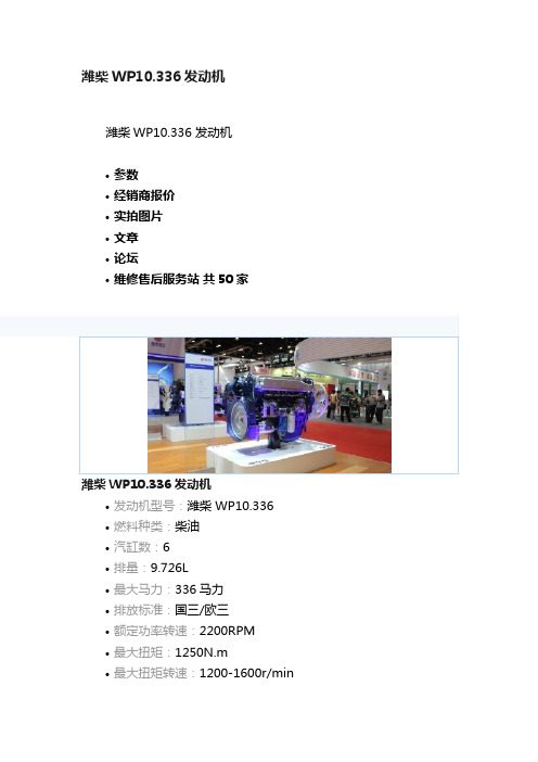
潍柴WP10.336发动机
潍柴WP10.336 发动机
•参数
•经销商报价
•实拍图片
•文章
•论坛
•维修售后服务站共50家
潍柴WP10.336 发动机
•发动机型号:潍柴 WP10.336
•燃料种类:柴油
•汽缸数:6
•排量:9.726L
•最大马力:336马力
•排放标准:国三/欧三
•额定功率转速:2200RPM
•最大扭矩:1250N.m
•最大扭矩转速:1200-1600r/min
潍柴WP10.336 发动机参数
发动机型号:潍柴 WP10.336
系列:WP10国III机发动机厂商:潍柴
适配范围:卡车柴油机
进气形式:增压中冷
汽缸数:纠错
6
燃料种类:柴油
汽缸排列形式:直列
排量:9.726L
排放标准:国三/欧三最大输出功率:247kw
额定功率转速:2200RPM
最大马力:336马力
最大扭矩:1250N.m
最大扭矩转速:1200-1600r/min
全负荷最低燃油耗
率:g/kW.h
发动机形式:水冷,四冲程,带排气门制动,直喷,增压中冷
发动机净重:875Kg
发动机尺寸:1525×730×1063mm
压缩比:
一米外噪音:<104dB
缸径x行程:126x130mm
每缸气门数:2个
点火次序:
潍柴WP10.336 发动机实拍图片
查看全国经销商报价>>。
- 1、下载文档前请自行甄别文档内容的完整性,平台不提供额外的编辑、内容补充、找答案等附加服务。
- 2、"仅部分预览"的文档,不可在线预览部分如存在完整性等问题,可反馈申请退款(可完整预览的文档不适用该条件!)。
- 3、如文档侵犯您的权益,请联系客服反馈,我们会尽快为您处理(人工客服工作时间:9:00-18:30)。
the
actual
machine
power
available
to
do
work
through
implements
and
work
tools.
It’s
much
more
than
just
the
engine
power
under
the
hood
–
it’s
a
core
strength
that
differentiates
reduces
engine
speed
and
pump
fl
ow
in
order
to
improve
controllability.
Monitor
The
336E
is
equipped
with
a
new
LCD
(Liquid
Crystal
Display)
monitor
that’s
40%
bigger
than
the
returns
to
normal
operating
level.
The
optional
heavy
lift
mode
increases
machine
system
pressure
to
improve
lift
–
a
nice
benefit
in
certain
situations.
Heavy
lift
mode
also
spillage
or
contamination.
A
sensor
attached
to
the
fi
lter
warns
the
operator
if
it
is
full
or
exceeds
a
certain
pressure
level.
Swing Priority Circuit
The
swing
priority
circuit
of
42 languages
to
support
today’s
diverse
workforce.
A
new
“Engine
Shutdown
Setting”
accessible
through
the
monitor
allows
owners
and
operators
to
specify
how
long
the
machine
Drawbar
Pull
Weight Minimum
Weight
Maximum
Weight
4.9
km/h
295
kN
36
570
kg
39
370
kg
3
mph
66,319
lbf
80,620
lb
86,796
lb
Introduction Since its introduction in the 1990s, the 300 Series family of excavators has become the industry standard in general, quarry, and heavy construction applications. The all-new E Series will continue that trend-setting standard. The first model in the new family, the 336E, meets today’s U.S., European Union, and Japan emissions standards. It is also built with several new fuel-saving and comfort-enabling features and benefits that will delight owners and operators. If you are looking for more productivity and comfort, less fuel consumption and emissions, and easier and more sensible serviceability, you will find it in the all-new 336E and the E Series family of excavators.
Work
Tools
............................................................8
Integrated
Technologies
..................................10
Serviceability .....................................................11
பைடு நூலகம்should
idle
before
shutting
down
the
engine,
which
can
save
significant
amounts
of
fuel.
In
previous
model’s
with
higher
resolution
for
better
visibility.
In addition to
an
improved
keypad
and
added
functionality,
it
is
programmable
to
provide
information
in
a
choice
needs for
comfort
and
productivity.
Controls
The
right
and
left
joystick
consoles
can
be
adjusted
to
meet
the
operator’s
desired
preference,
making
him
(or
her)
more
comfortable
The
return
filter
is
a
capsuletype
design
with
a
cartridge
inside.
Unlike
many
competitors’
offerings,
the
Cat
cartridge
features
a
handle
to
help
remove
and
change
without
oil
336E
L
Hydraulic
Excavator
Specifi
cations
....................................................15
336E
L
Standard
Equipment.............................28
336E
L
Optional
Equipment
..............................29
Hydraulics
Hydraulic Horsepower
Power
to
move
more
dirt,
rock,
and
debris
with
speed
and
precision
Hydraulic
horsepower
Safety
..................................................................12
Complete
Customer
Care.................................13
Sustainability
.....................................................14
valve
attachments
mount
on
top
of
the
main
valve,
which
allows
for
auxiliary
hydraulic
lines
and
valve
configurations
to
be
simplified
for
greater
reliability.
Return Filter
...................................................................5
Structures
and
Undercarriage