Performance enhancing dr讲义ugs-2
Crucial P2 SSD说明书

/P2Impressive speeds up to 2400MB/s 4 Limited 5-year warranty Whether you’re at work, in the game, or on the go, ordinary bootup speeds can frustrate your best laid plans. Good thing the Crucial ® P2 SSD really flies. With plenty of storage and performance accelerated by NVMe ™ technology, the P2 has the speed and dependability you need to explore your computer’s potential.CRUCIAL P2 SSDBoost your computer’s potential.Fast, affordable, reliable. All the speed you need at a price that won’t break the bank.Do More. Wait Less.Experience the NVMe ™ difference. The Crucial P2 unlocks the performance of your computer, delivering shorter load times and faster data transfers¹.Lasting Reliability Backed by thousands of validation hours, dozens of qualification tests, a heritage of award-winning SSDs, and a 5-year limited warranty².Peace of Mind Includes SSD management software for performance optimization, data security, and firmware updates.One of the Largest Storage Manufacturers Worldwide Crucial ® is backed by the quality and engineering innovation you’ve come to expect fromMicron, the producer of some of the world’s most advanced memory and storage technologies for over 40 years.1. Speed comparison based on published specs of the Crucial P1 SSD and the Crucial MX500 SSD.2. W arranty valid for five years from the original date of purchase.3. S ome of the storage capacity is used for formatting and other purposes and is not available for data storage. 1GB equals 1 billion bytes. Not all capacities available at initial launch.4. T ypical I/O performance numbers as measured using CrystalDiskMark® with write cache enabled, a queue depth of 64 (QD = 8, Threads = 8). Fresh out-of-box (FOB) state is assumed. For performance measurement purposes, the SSD may be restored to FOB state using the secure erase command. System variations will affect measured results.©2020 – 2021 Micron Technology, Inc. All rights reserved. Information, products, and/or specifications are subject to change without notice. Neither Crucial nor Micron Technology, Inc. is responsible for omissions or errors in typography or photography. Micron, the Micron logo, Crucial, the Crucial logo, and the memory &storage experts are trademarks or registered trademarks of Micron Technology, Inc. All other trademarks are the property of their respective owners.Life Expectancy (MTTF) 1.5 million hours Endurance - Total Bytes Written (TBW) 2TB SSD = 600TB (TBW)1TB SSD = 300TB (TBW)500GB SSD = 150TB (TBW)250GB SSD = 150TB (TBW)Data Transfer Software Acronis ® True Image™ for Crucial ® cloning software Operating Temperature 0 °C to 70 °C Compliance CE, FCC, VCCI, KC, RCM, ICES, Morocco, BSMI,Ukraine, UL, TUV, China RoHS, WEEE Advanced Features • Dynamic Write Acceleration • Redundant Array of Independent NAND (RAIN)• Multistep Data Integrity Algorithms • Adaptive Thermal Protection • Integrated Power LossImmunity • Active GarbageCollection • TRIM Support • NVMe standard Self-Monitoring and Reporting Technology (SMART)• Error Correction Code (ECC)• NVMe AutonomousPower State Transition(APST) SupportWarranty Limited 5-year warranty 2Installation For easy-to-follow instructions and our step-by-step guide, visit /ssd-installSupportFor more resources and warranty information, visit /support。
PNY 品牌 Quadro 产品线的 RTX 5000 显卡说明文档说明书

PNY Technologies, Inc. 100 Jefferson Road, Parsippany, NJ 07054 Tel 408 567 5500 | Fax 408 855 0680For more information visit: /quadro 1 NVIDIA NVLink sold separately | 2 Connecting two RTX 5000 cards with NVLink to scale performance and memory capacity to 32 GB is only possible if your application supports NVLink technology. Please contact your application provider to confirm their support for NVLink | 3 In preparation for the emerging VirtualLink standard, Turing GPUs have implemented hardware support according to the “VirtualLink Advance Overview”. To learn more about VirtualLink, please see | 4 Via adapter/connector/bracket | 5 Quadro Sync II card sold separately | 6 Windows 7, 8, 8.1, 10 and Linux | 7 GPU supports DX 12.0 API, Hardware Feature Level 12_1 | 8 Product is based on a published Khronos Specification, and is expected to pass the Khronos Conformance Testing Process when available. Current conformance status can be found at /conformance© 2018 NVIDIA Corporation and PNY. All rights reserved. NVIDIA, the NVIDIA logo, Quadro, nView, CUDA, and NVIDIA Turing are trademarks and/or registered trademarks of NVIDIA Corporation in the U.S. and other countries. The PNY logotype is a registered trademark of PNY Technologies. OpenCL is a trademark of Apple Inc. used under license to the Khronos Group Inc. All other trademarks and copyrights are the property of their respective owners. NOV18REAL TIME RAY TRACING FOR PROFESSIONALSShatter the boundaries of what’s possible with the NVIDIA ® Quadro RTX ™ 5000, powered by NVIDIA Turing GPU to bring real-time ray tracing and accelerated AI to next-generation workflows. Creative and technical professionals can supercharge demanding design and visualization workloads and make more informed decisions faster than ever before. Equipped with 3072 CUDA cores, 384 Tensor cores, 48 RT Cores and 16GB GDDR6 memory, Quadro RTX 5000 can render complex models and scenes with physically accurate shadows, reflections, and refractions to empower users with instant insight. Support for NVIDIA NVLink 1 enables applications to scale memory and performance with multi-GPU configurations 2. And with the industry’s first implementation of the new VirtualLink ®3, Quadro RTX 5000 provides connectivity to the next-generation of high-resolution VR head-mounted displays to let designers view their work in the most compelling virtual environments possible.Quadro cards are certified with a broad range of sophisticated professional applications, tested by leading workstation manufacturers, and backed by a global team of support specialists. This gives you the peace of mind to focus on doing your best work. Whether you’re developing revolutionary products or telling spectacularly vivid visual stories, Quadro gives you the performance to do it brilliantly. FEATURES >Four DisplayPort 1.4 Connectors >VirtualLink Connector 3 >DisplayPort with Audio >VGA Support 4 >3D Stereo Support with Stereo Connector 4 >NVIDIA GPUDirect ™ Support >Quadro Sync II 5 Compatibility >NVIDIA nView ® Desktop Management Software >HDCP 2.2 Support >NVIDIA Mosaic 6PACKAGE CONTENTS >NVIDIA Quadro RTX 5000 >Quadro RTX Quick Start Guide >Quadro Support Guide >1 DisplayPort to DVI Adapter >1 Auxiliary Power Cable (8-pin to dual 6-pin adapter)WARRANTY AND SUPPORT >3-Year Warranty >Pre- and Post-Sales Technical Support >Dedicated Field Application Engineers >Direct Tech Support Hot Lines PNY PART NUMBER VCQRTX5000-PB SPECIFICATIONS GPU Memory 16 GB GDDR6Memory Interface 256-bit Memory Bandwidth Up to 448 GB/s ECC Yes NVIDIA CUDA Cores 3,072NVIDIA Tensor Cores 384NVIDIA RT Cores 48Single-Precision Performance 11.2 TFLOPS Tensor Performance 89.2 TFLOPS NVIDIA NVLink Connects 2 Quadro RTX 5000 GPUs 1NVIDIA NVLink bandwidth 50 GB/s (bidirectional)System Interface PCI Express 3.0 x 16Power Consumption Total board power: 265 W Total graphics power: 230 W Thermal Solution Active Form Factor 4.4” H x 10.5” L, Dual Slot, Full Height Display Connectors 4xDP 1.4, 1x USB-C Max Simultaneous Displays 4x 4096x2160 @ 120 Hz, 4x 5120x2880 @ 60 Hz, 2x 7680x4320 @ 60 HzEncode / Decode Engines 1X Encode, 2X DecodeVR Ready YesGraphics APIs DirectX 12.07, Shader Model 5.17, OpenGL 4.58, Vulkan 1.08Compute APIs CUDA, DirectCompute, OpenCL ™THE WORLD’S FIRST RAY TRACING GPU NVIDIA QUADRO RTX 5000。
Performance Guide for ViDi说明书

Performance Guide for ViDi18-Mar-2019 16:11:24 EDTThinking about PerformanceTool and stream processing timeThroughputPerformance ToolkitApplication DesignTool ParametersNVIDIA GPU Selection and ConfigurationNVIDIA Device Branding SummaryGraphics Card RequirementsConsiderationsEstimating Run-Time PerformanceGlossary of Standard NVIDIA GPU TerminologyMultiple GPUsSystem Configuration for Multi-GPU SystemsWhat About Training Time?Thinking about PerformanceWhat performance aspect is important to you?Tool and stream processing timeIndividual tool processing time is shown in the Database Overview panel:averageThe reported time is the processing time for all of the images processed during the most recent processing.The processing time for a stream containing multiple tools is not available through the ViDi Suite GUI, and you cannot estimate it by summing the tool execution time, as it includes the time required to prepare and transmit view information between tools.When thinking about stream processing, remember that the processing of tools in a ViDi stream is always serialized when you call Stream. Process()Tool.Process() . Only one tool is ever processed at a time unless you explicitly process tools individually using .ThroughputThroughput refers to the total number of images that can be processed per unit time. If your application can process multiple streams concurrently using different threads, it may be able to improve system throughput, although individual tool processing will be slower.Performance ToolkitIn terms of increasing expense (but not efficacy):Application designTool parametersSystem configurationHardware optionsMultiple GPUsApplication DesignThe following table summarizes application design characteristics that may produce faster run-time performance. Application design choices that improve performance typically have minimal impact on the behavior of the system.Design Pattern Why it's Faster Best Bang for Buck But Watch Out ForUse a small number of tools per stream.The processing time for a singleViDi tool does vary significantlynotbased on the amount of informationthat the tool returns.For example, a single Blue tool thatis trained to find 100 differentfeatures runs at the same speed asa tool that is trained to find only asingle feature. Further, the numberof features returned makes only aminimal speed difference.Similarly, a Red tool runs at thesame speed regardless of howmany defects it finds, and a Greentool can classify into 2 classes or2000 classes at the same speed.Start building your application with asingle tool.Avoiding Image Conversions During tool operation, the imagemust be sampled for processing bythe neural network. This samplingrequires a raster (uncompressed)format image such as a bitmap.Performing this conversion takestime.Similarly, if the tool is configured touse a single-channel (grey-scale)image as input, but the suppliedimages are multi-channel colorimages, the luminance value mustbe computed for each image at runtime.Attempt to solve your applicationusing a single-channel grey-scaleimage.Some applications require colorinformation.Reduce the amount of processed data Reducing the number of processeddata by:Using a smaller ROIUsing a maskUsing as few image channels aspossibleImproves processing speed byreducing the total amount of dataprocessed.Restricted ROI ViDi tools need contextualinformation to work well – don'tconstrain the ROI too much.Downsampling is usually not needed– selecting a larger feature size canimprove speed and remove theneed for run-time downsampling.Multi-threading On systems with multiple GPUs,processing multiple streamsconcurrently allows tools to executein parallel, increasing throughput.On single-GPU systems, you canconfigure the system to allowmultiple processes to make use ofthe same GPU. This allows a higherGPU occupancy and can improvethroughput, although tool executiontime will e the --max-process-countcommand line argument to enablemultiple threads to access a singleGPU.To enable multi-process GPUaccess for a runtime applicationusing the local control's GlobalConfimethod:g()control.GlobalConfig("max_process_count=2");Processing time for an individual toolwill increase.C++ (unmanaged)Use of an unmanaged languageenvironment reduces the impact ofsystem activity on tool execution.For low-latency, high-performanceapplications, use the C++ API.Windows is not a RTOSTool ParametersTool parameter choices directly effect tool execution speed, but there is typically a tradeoff between tool speed and accuracy or robustness. Tool Parameter How it Affects Speed Best Bang for Buck But Watch Out ForFeature size At run time, ViDi tools need tosample the entire input image. Thefeature size determines the numberof samples required for a givenimage size. The larger the featuresize, the fewer the samples.O(n)2 increase in speed with largerfeature size.Larger feature sizes may cause thetool to miss features or defects.Use parameter optimization to findan optimal size.Sampling Density Similarly to feature size, thesampling density determines thenumber of samples required for agiven image size.O(n)2 increase in speed with lowersampling density.Risk of missing features or defects.Refinement Parameters The Blue and Red tools includeprocessing-time parameters thatprovide more accurate results at thecost of increasing execution time:Blue tool: PrecisionRed tool: Iterations Increasing the iteration value increases processing time linearly.Low-precision mode If your system meets certain specificrequirements (CUDA ComputeCapability 6.1 or greater), you canenable mlow-precision processingode for any ViDi tool.Enabling low-precision modeconverts any existing trained tool touse low-precision computationduring processing, and it generateslow-precision tools for all futuretraining operations until it isdisabled. (Once a tool has beenconverted to low-precision mode, itmust be retrained to disable low-precision mode.Low-precision tools can executefrom 25% to as much as 50% fasterthan normal-precision tools.Additional run-time speedimprovements for low-precision toolsare seen on systems with TuringTensor cores.Changing a tool to low-precisionmode may change the results thetool produces to a small degree.Generally high-level featureidentification, defect classification,and general classification will beunchanged, but specific feature anddefect regions and scores maychange slightly.NVIDIA GPU Selection and ConfigurationSystem configuration choices directly affect tool processing speed without affecting tool accuracy or behavior. They are the most expensive and hardest to predict the effect of.Configuration Option Why it's Faster Best Bang for Buck But Watch Out ForNVIDIA Device Type The number of CUDA cores isdirectly related to high-precisionprocessing speed and training.The number of standard Tensorcores is directly related toprocessing speed and trainingspeed.The number of Tensor coresTuringis related to processing speed in low-precision mode only. These coresdo not affect standard precisionprocessing or training speed.NVIDIA Driver ModeConsumer-grade gaming-oriented NVIDIA devices only support the WDDM device driver model. This driver is intended to supportgraphics display, not computation.Professional-grade NVIDIA cards support the TCC driver mode, which provides better performance and stability.Select a Quadro or Tesla (or selected Titan)-branded NVIDIA card.If using a GeForce-branded card, be aware that NVIDIA Geforce drivers are updated frequently and may not be compatible with ViDi. Please visit Cognex's support page for driver recommendations.Using TCC mode driver prevents the use of Video output on the GPU card; use onboard video instead.Optimized memoryViDi optimized memory, which is enabled by default, improves performance by overriding the standard NVIDA GPU memory management system.Make sure your card has at least 4GB of GPU memory.Performance improvement is not as significant for cards using the TCC driver.NVIDIA Device Branding SummaryThe following table summarizes the different NVIDIA device types.Class ConsumerProfessionalBrandingGeForceTitanQuadroTeslaVolta Architecture Cards ---Titan V GV100V100Pascal Architecture Cards GTX 1xxx Titan Xp G/GPxxx P100Turing Architecture Cards RTX 2xxx Titan RTX Quadro RTX4xxx T4Video Output Yes Yes Yes ---Price Point$1K $3K $5K $5K+TCC Driver Support --- Yes Yes Yes ECC Memory ------ YesYes Tensor CoresRTX2xxx and newer:Yes Titan V :Yes Titan RTX:Yes Quadro RTX :Yes Quadro GV100:Yes V100:Yes T4:Yes Graphics Card RequirementsNVIDIA® CUDA® enabled GPUCUDA compute capability 3.0 or higherConsiderationsWhile consumer cards and professional cards perform similarly, some considerations should be made:Heat dissipationProfessional cards are intended for continuous duty cycle use and are designed to dissipate heat effectively.SupplyProfessional cards are manufactured by NVIDIA and have a longer product cycle.Performance and ControlProfessional cards support the TCC mode drivers. This allows the GPU to run as a computing device with no display output.This means you will need a second card for display (or use the motherboard's built-in display).Estimating Run-Time PerformanceThe following numbers are an approximate guide to the potential performance increment for different card families (baseline = non-run-time TensorCore, standard mode):ViDi Operating Mode No Tensor Cores (ex GTX)Volta Tensor Cores (ex V100)Turing Tensor Cores (ex T4)Standard 100%150%150%Low-precision125%125%175%Glossary of Standard NVIDIA GPU TerminologyTerm What it isIs it important?CUDA CoreStandard NVIDIA parallel processing unit.Yes . This is the 'standard' measure of NVIDIA GPU processing – the number of CUDA cores. The more cores, the faster the ViDi processing and training.ECC Memory Error-correcting-code memoryHardware support for verifying that memory reads/writes do not contain errors.No Because of the huge number of computations involved in training andprocessing neural networks, the likelihood of a memory error affecting a tool result is very low.TCC Tesla Compute Cluster (Driver).A high-performance driver that is optimized for computational use of an NVIDIA GPU.Not supported by all cardsDisables video output from the card Provides faster training and runtime performanceDiminishes or eliminates the advantages of using ViDi optimized memoryConfigured using the nvdia-smi utilityYes . Whenever possible, customers should select cards that support the TCC driver mode, and they should enable the mode.Tensor CoreFull-precision, mixed-precision (and evt. integer math) parallel processing unit dedicated to matrix multiply operations.Yes . Starting with ViDi 3.2, ViDiautomatically takes advantage of tensor cores for faster processing and training, as long as the user has a Standard or Advanced license.TensorRTNVIDIA framework for optimizing (by using low-precision and integer math) run-time performance of TensorFlow, Caffe, and other standard framework networks running on a GPU with Tensor Cores.No: ViDi uses a proprietary network architecture that is not compatible with Tensor RT.Multiple GPUsExcept under very narrow circumstances, using multiple GPUs in a single system will not reduce ViDi tool training or processing time. What multiple GPUs do is to:can Increase system throughput when your application uses multiple threads to concurrently process images Increase training productivity, by allowing you to train multiple tools at the same timeThere is one circumstance under which multiple GPUs can be used to reduce tool processing time. If you configure your system in MultipleDevic mode, then all installed s are treated as a single . This means that only one tool can be processed at a esPerTool GPU GPU during processing time for the entire server.NoteIn comparison with other Tesla cards, the T4 is oriented toward run-time operation. It supports ViDi training and run-time, but training performance will likely be slower than a V100.In the specific case of a Red Analyze tool, the use of may speed up the tool, especially a tool with a high image-MultipleDevicesPerTool modeto-feature size ratio. However, this potential speed up comes at the expense of latency across all clients.System Configuration for Multi-GPU SystemsWhen configuring a host system for multiple GPUs, keep the following in mind:The chassis may need to provide up to 2KW of powerQuadro and Tesla cards provide better cooling configuration for multiple-card installationsMake sure that the PCIe configuration has 16 PCIe lanes available for each GPUDo not enable SLIWhat About Training Time?Reducing tool training time does not affect your performance at run time, but it can improve the productivity of your development team.ViDi training uses a mixture of CPU and GPU resources. When considering training specifically, there are three phases: computing image statistics, building the model, and then processing the image set with the newly trained model. The model building phase of training usually takes the longest, and it is an iterative process. Each iteration requires that the tool generate training data from all of the training images. If the images are in a non-BMP format, they need to be converted to BMP for each iteration.Tool training is always single-threaded and single GPU. You cannot make training faster using multiple GPUs.canUsing multiple GPUs improve your productivity because you can train multiple tools concurrently.。
ISR G2产品介绍(external)
© 2009 Cisco Systems, Inc. All rights reserved.
Cisco Confidential
14
Cisco 1900 系列
Integrated Services Routers
19411941W 1941W1941
SM SM Slots Slots ISM ISM Slots Slots EHWIC EHWIC Slots Slots 0 0 0 0 Fixed 802.11n 802.11n Fixed 1 1 Radio Radio 2 2 2 GE 0 2 2 GE 0 2 2 GE 0
Default DRAM
Form Factor
1 GB
3RU
1 GB
3RU
ISR G2 TDM
© 2009 Cisco Systems, Inc. All rights reserved.
Cisco Confidential
12
全新 3900E 系列
高性价比中端路由器
Services Performance Engine 250 Services Performance Engine 200
Secure Mobility Platform
o
性能提升,2个EHWIC接口
Onboard WAN Onboard WAN Ports Ports2 GE Onboard DSP Onboard DSP Slots Slots Default Default Flash Flash Default Default DRAM DRAM Form Form Factor Factor 0
ISR G2 TDM
© 2009 Cisco Systems, Inc. All rights reserved.
HDS USP日常维护工作

悉 DCI(Define config install)的 51 个步骤; 3. 学习 345 课程第六章,熟悉存储扩容时如何规划,怎么连接物理 线路,及如何定义配置; 4. 熟 悉 如 何 Install 和 De-install 常 见 部 件 , 如 硬 盘 , 内 存 , ShareMemory,DKA,CHA 等的方法; 5. 掌握光纤交换划 ZONE, 存储 LUN mapping,主机识别并配置磁盘, 安装配置 hdlm 的方法,了解升级 hdlm 的步骤,方法及注意事项; 6. 掌握查看主机上卷的状态,以及盘路 offline 时的处理方法,熟悉 映射的卷与 HBA 之间的关系;判断交换机的运行情况,常见故障 的 trouble shooting 7. 熟悉 microcode 升级的大概步骤,及其注意事项; 8. 学习 TrueCopy 及 ShadowImage 有关知识。
ቤተ መጻሕፍቲ ባይዱ
后端板 DKA 与前端口 CHA 的作用及其在 USP 上的插槽分布;
后端板 DKA 连接 SM 和 HDD 的,在 DKA PCB 上有 MP 用作磁盘 I/O 数据处理、将磁盘 mapping 给对应 CHA port。 DKA PCB 为 8 Ports 2Gbps Fiber Loop 连接 FSW。 前端口 CHA 连接主机(交换机) ,mapping 给主机。 CHA PCB 分为下图所示,8 Ports、16 Ports、32 Ports 的 Fiber 板和 8 Ports 的 NAS 板和 iSCSI 板。
硬盘槽位的表述方法:例如硬盘 HDDR10-04 “HDDR1”表示 HDU-R1 “0”表示 HDU Numbering 中 0-7,8-f 使用后面槽位表示。 “04”表示 R1 的 HDU 0 中的 04 号盘,硬盘的安装顺序见图 DKU505I HDU Box – Installation Order,如果 是 10-17 则表示 HDU Numbering 8-f。如下举例说明: HDDR17-0E 表示 R1 中 HDU 7 的第 0E 块硬盘,即 0E 位置的硬盘 HDDL26-1B 表示 L2 中 HDU e 的第 0B 块硬盘,即 1B 位置的硬盘 HDDR17-19 表示 R1 中 HDU f 的第 09 块硬盘,即 19 位置的硬盘
aida2 英文手册

aida2 英文手册Title: AIDA2 English ManualIntroduction:The AIDA2 English manual serves as a comprehensive guide for users of the AIDA2 software. This article aims to provide an accurate and detailed overview of the manual's content. The structure of the article includes an introduction, main body with five major points, and a conclusion.Main Body:1. Installation and Setup:1.1 System Requirements: This section outlines the minimum hardware and software specifications needed to install and run AIDA2.1.2 Installation Process: Step-by-step instructions are provided to guide users through the installation process, ensuring a smooth setup.1.3 Configuration: Details on configuring AIDA2 for optimal performance and compatibility with different operating systems and environments.2. User Interface:2.1 Navigation: This part explains the various menus, buttons, and options available in the AIDA2 user interface, allowing users to easily navigate through the software.2.2 Data Input: Detailed instructions on how to input and import data into AIDA2, including different file formats supported.2.3 Data Visualization: This section covers the visualization capabilities of AIDA2, such as graphs, charts, and tables, to help users interpret and analyze data effectively.3. Analysis Tools:3.1 Statistical Analysis: AIDA2 offers a range of statistical analysis tools, including descriptive statistics, hypothesis testing, and regression analysis. Each tool is explained in detail, along with its purpose and usage.3.2 Data Mining: This part focuses on the data mining capabilities of AIDA2, including clustering, association rule mining, and decision tree analysis. Users are guided through the steps required to perform these analyses.3.3 Machine Learning: AIDA2 provides machine learning algorithms for predictive modeling, classification, and regression. This section explains the theory behind these algorithms and demonstrates their application.4. Advanced Features:4.1 Customization: AIDA2 allows users to customize their analysis by adjusting parameters, selecting algorithms, and creating custom functions. This section provides instructions on how to utilize these advanced features.4.2 Scripting: Users with programming skills can take advantage of AIDA2's scripting capabilities. This part explains the scripting language used in AIDA2 and provides examples of how to automate tasks and extend functionality.4.3 Integration: AIDA2 can be integrated with other software and databases. This section covers the integration process and provides guidelines for seamless data exchange.5. Troubleshooting and Support:5.1 Common Issues: This section addresses common problems users may encounter while using AIDA2 and provides troubleshooting tips to resolve them.5.2 Online Resources: AIDA2 offers online resources such as user forums, FAQs, and tutorials. Users are guided on how to access these resources for additional support.5.3 Technical Support: Contact information for technical support is provided, ensuring users can seek assistance when needed.Conclusion:In conclusion, the AIDA2 English manual serves as a comprehensive guide for users, covering installation, user interface, analysis tools, advanced features, and troubleshooting. By following the instructions and utilizing the resources provided, users can effectively utilize AIDA2 for their data analysis needs.。
CISCOswitch讲稿3
NetFlow feature card
Supervisor Engine II
Supervisor Engine III
Upgrade option
NFFC + Software enables multilayer switching
北京华教公司
Catalyst 5500 System Components
北京华教公司
Catalyst 5500 Architecture
Two high-capacity switching fabrics Cell and frame switching on a single platform Cost-effective input/output (I/O) queuing model management and index/control buses Scales from 3.6 Gbps to 50 Gbps
10-*
北京华教公司
Catalyst 5000 Family Route Switch Module
北京华教公司
Route Switch Module
Redundancy HSRP, SSRP Multimedia PIM, CGMP Security Access lists, encryption Class of Service RSVP, WFQ NetFlow
Catalyst 5000 Supervisor Engines
北京华教公司
Supervisor Engines
Price/performance
Supervisor II
Supervisor III
Schneider Electric ТеSys GV2设备手册说明书

T h e i n f o r m a t i o n p r o v i d e d i n t h i s d o c u m e n t a t i o n c o n t a i n s g e n e r a l d e s c r i p t i o n s a n d /o r t e c h n i c a l c h a r a c t e r i s t i c s o f t h e p e r f o r m a n c e o f t h e p r o d u c t s c o n t a i n e d h e r e i n .T h i s d o c u m e n t a t i o n i s n o t i n t e n d e d a s a s u b s t i t u t e f o r a n d i s n o t t o b e u s e d f o r d e t e r m i n i n g s u i t a b i l i t y o r r e l i a b i l i t y o f t h e s e p r o d u c t s f o r s p e c i f i c u s e r a p p l i c a t i o n s .I t i s t h e d u t y o f a n y s u c h u s e r o r i n t e g r a t o r t o p e r f o r m t h e a p p r o p r i a t e a n d c o m p l e t e r i s k a n a l y s i s , e v a l u a t i o n a n d t e s t i n g o f t h e p r o d u c t s w i t h r e s p e c t t o t h e r e l e v a n t s p e c i f i c a p p l i c a t i o n o r u s e t h e r e o f .N e i t h e r S c h n e i d e r E l e c t r i c I n d u s t r i e s S A S n o r a n y o f i t s a f f i l i a t e s o r s u b s i d i a r i e s s h a l l b e r e s p o n s i b l e o r l i a b l e f o r m i s u s e o f t h e i n f o r m a t i o n c o n t a i n e d h e r e i n .Product data sheetCharacteristicsGV2ME08TeSys GV2 Manual Starter and Protector,thermal magnetic circuit protector, pushbuttons, 2.5 to 4 A, screw clampProduct availability: Stock - Normally stocked in distribution facilityMainRange TeSys Product name TeSys GV2Device short name GV2ME Device application MotorTrip unit technologyThermal-magneticComplementaryPoles description 3P Network type ACUtilisation category AC-3 IEC 60947-4-1Category A IEC 60947-2Network frequency 50/60 Hz IEC 60947-4-1Fixing mode 35 mm symmetrical DIN rail clipped Panel screwed with adaptor plate)Operating position Any positionMotor power kW1.1 KW 400/415 V AC 50/60 Hz 1.5 KW 400/415 V AC 50/60 Hz 1.5 KW 500 V AC 50/60 Hz 3 KW 690 V AC 50/60 Hz2.2 KW 500 V AC 50/60 Hz 2.2 kW 690 V AC 50/60 HzBreaking capacity100 KA Icu 230/240 V AC 50/60 Hz IEC 60947-2100 KA Icu 400/415 V AC 50/60 Hz IEC 60947-2100 KA Icu 440 V AC 50/60 Hz IEC 60947-2100 KA Icu 500 V AC 50/60 Hz IEC 60947-23 kA Icu 690 V AC 50/60 Hz IEC 60947-2[Ics] rated service short-circuit breaking capacity100 % 500 V AC 50/60 Hz IEC 60947-2100 % 230/240 V AC 50/60 Hz IEC 60947-2100 % 440 V AC 50/60 Hz IEC 60947-2100 % 400/415 V AC 50/60 Hz IEC 60947-275 % 690 V AC 50/60 Hz IEC 60947-2Control type Push-button Line Rated Current4 A Thermal protection adjustment range 2.5…4 A Magnetic tripping current 51 A[Ue] rated operational voltage 690 V AC 50/60 Hz IEC 60947-2[Ui] rated insulation voltage690 V AC 50/60 Hz IEC 60947-2[Ith] conventional free air thermal current 4 A IEC 60947-4-1[Uimp] rated impulse withstand voltage 6 kV IEC 60947-2Power dissipation per pole 2.5 W Mechanical durability 100000 cyclesElectrical durability 100000 cycles AC-3 440 V Maximum operating rate25 cyc/hRated duty Continuous IEC 60947-4-1Connections - terminals Screw clamp terminals 2 0.00…0.01 in² (1…6 mm²) solidScrew clamp terminals 2 0.00…0.01 in² (1.5…6 mm²) flexible without cable endScrew clamp terminals 2 0.00…0.01 in² (1…4 mm²) flexible with cable end Tightening torque15.05 lbf.in (1.7 N.m) screw clamp terminalsSuitability for isolation Yes IEC 60947-1Phase failure sensitivity Yes IEC 60947-4-1Height 3.50 in (89 mm)Width 1.77 in (45 mm)Depth 3.09 in (78.5 mm)Net weight0.57 lb(US) (0.26 kg)EnvironmentStandards EN/IEC 60947-2EN/IEC 60947-4-1CSA C22.2 No 60947-4-1UL 60947-4-1Product certifications IECEE CB SchemeULCSACCCEACATEXBVLROS (Lloyds register of shipping)DNV-GLRINAProtective treatment THIP degree of protection IP20 IEC 60529IK degree of protection IK04Ambient air temperature for operation-4…140 °F (-20…60 °C)Ambient air temperature for storage-40…176 °F (-40…80 °C)Fire resistance1760 °F (960 °C) IEC 60695-2-1Operating altitude6561.68 ft (2000 m)Ordering and shipping detailsCategory22367 - MANUAL STR PROTECTOR - GV2Discount Schedule I11GTIN00785901211952Package weight(Lbs)0.26 kg (0.58 lb(US))Returnability YesCountry of origin THOffer SustainabilitySustainable offer status Green Premium productREACh Regulation REACh DeclarationEU RoHS Directive Compliant EU RoHS DeclarationMercury free YesRoHS exemption information YesChina RoHS Regulation China RoHS DeclarationEnvironmental Disclosure Product Environmental ProfileCircularity Profile No need of specific recycling operationsWEEE The product must be disposed on European Union markets following specificwaste collection and never end up in rubbish bins.Contractual warrantyWarranty18 monthsProduct data sheetPerformance CurvesGV2ME08Thermal-Magnetic Tripping Curves for GV2ME and GV2PAverage Operating Times at 20 °C Related to Multiples of the Setting Current1 3 poles from cold state2 2 poles from cold state3 3 poles from hot stateCurrent Limitation on Short-Circuit for GV2ME and GV2P (3-Phase 400/415 V))Dynamic StressI peak = f (prospective Isc) at 1.05 Ue = 435 V1Maximum peak current224-32 A320-25 A417-23 A513-18 A69-14 A76-10 A84-6.3 A9 2.5-4 A10 1.6-2.5 A111-1.6 A12Limit of rated ultimate breaking capacity on short-circuit of GV2ME (14, 18, 23, and 25 A ratings).Thermal Limit on Short-Circuit for GV2METhermal Limit in kA2s in the Magnetic Operating ZoneSum of I2dt = f (prospective Isc) at 1.05 Ue = 435 V124-32 A 220-25 A 317-23 A 413-18 A 59-14 A 66-10 A 74-6.3 A8 2.5-4 A9 1.6-2.5 A 101-1.6 AProduct data sheetDimensions DrawingsGV2ME08DimensionGV2ME(1)MaximumMountingGV2ME On 35 mm railc = 78.5 on AM1 DP200 (35 x 7.5)c = 86 on AM1 DE200, ED200 (35 x 15)On panel with adapter plate GV2AF02On pre-slotted plate AM1 PAOn rails DZ5 MB201GV2AF01Combination GV2ME + TeSys k contactorGV2AF3Combination GV2ME + TeSys d contactorGV2AF4 + LAD311Combination GV2ME + TeSys d contactorGV2ME + GV1L3 (Current Limiter)X1 = 10 mm for Ue = 230 V or 30 mm for 230 V < Ue ≤ 690 VProduct data sheetGV2ME08 Connections and SchemaGV2ME•• and GV2RTConnection of Undervoltage Trip for Dangerous Machines (Conforming to INRS) on GV2ME Only。
Ersa Rework System HR 600 2 说明书

14HR 600/2REWORK MADE EASY. IN ALL DIMENSIONS.For more than a decade now, over 5,000 users worldwide are drawing benefits from using the patented IR rework technology. Aside from its very attractive price-perfor-mance ratio, the units have gained their strong market position because they de-liver excellent results even with the most complex rework tasks.Ersa has a model diversity that extends to automated hybrid stations with extensive accessories.The compact system HR 200 for rework applications “out of the box” convinces professionals and beginners not only with its easy setup, but also with its intuitive operation.HR 100HR 200HR 550HR 600 XL: For the largest ErsaRework system, an XL heatinghead is also available as anoption. 120 x 120 mm edgelength can be processed.REWORKThe hybrid rework system HR 600/2, sets standards in the automated rework of PCBs.In addition, Ersa offers the HR 550 – a fur-ther high-performance model for safe and easy manual rework with guided processes. The latest Ersa system, the HR 600 XL, has been developed for large PCB formats of up to 625 x 625 mm and handles component sizes of 60 x 60 mm without any problems. Thanks to the innovative IR Matrix Heater™ and 16 kW power, the HR 600 XL ensures the safe processing oflarge, high-mass assemblies.15REWORK News from the Rework family.At productonica 2019, Ersa will present three brand new systems for assembly repair, expanding the successful rework product line.The youngest members of the family inspire with their interesting technological features in the field of heating and place-ment technology and expand the variety of options for users.With the HR 550 XL, Ersa provides a semi-automatic system for large assem-blies up to approx. 530 x 610 mm. A real performance package with eight bottom radiator heating zones and motorized X-/Y-fine adjustment and component rotation. The system is suitable for industrial and power electronics as well HR 600/3P HR 550 XL HR 500NEW as large-format printed circuit boards and is particularly attractive for service providers.If you are looking for a system with the highest precision requirements, the HR 600/3P will automatically repair fine pitch components such as µBGA and the smallest chip components (01005). The high-precision axis system and 5-MPix cameras offer the most precise desolder-ing and placement technology in rework available today. Finally, the new HR 500 presents the full Ersa Hybrid Rework technology for budget oriented users. The HR 550's little brother allows flexible repair of standard assem-blies up to 380 x 300 mm and 50 x 50 mm component sizes.NEW NEWHighest precision and reliability for every conceivable component size (from 01005) is guaranteed with Ersa Rework systems.Guided processes in HRSoft 2.0 and with a 5-MPx camera ensure perfect and reproducible rework results.Screenshot shows the screenshot of a 01005 component placement.。
AOC-S100G-m2C User's Guide

User's GuideRevision 1.0AOC-S100G-m2CUser's Guide Revision 1.0Release Date: Aug 30, 2018Unless you request and receive written permission from Super Micro Computer, Inc., you may not copy any part of this document.Information in this document is subject to change without notice. Other products and companies referred to herein are trademarks or registered trademarks of their respective companies or mark holders.Copyright © 2018 by Super Micro Computer, Inc.All rights reserved. Printed in the United States of AmericaThe information in this User's Guide has been carefully reviewed and is believed to be accurate. The vendor assumes no responsibility for any inaccuracies that may be contained in this document, and makes no commitment to update or to keep current the information in this user's guide, or to notify any person or organization of the updates. Please Note: For the most up-to-date version of this user's guide, please see our Website at .Super Micro Computer, Inc. ("Supermicro") reserves the right to make changes to the product described in this user's guide at any time and without notice. This product, including software and documentation, is the property of Supermicro and/or its licensors, and is supplied only under a license. Any use or reproduction of this product is not allowed, except as expressly permitted by the terms of said license.IN NO EVENT WILL SUPER MICRO COMPUTER, INC. BE LIABLE FOR DIRECT, INDIRECT, SPECIAL, INCIDENTAL, SPECULATIVE OR CONSEQUENTIAL DAMAGES ARISING FROM THE USE OR INABILITY TO USE THIS PRODUCT OR DOCUMENTATION, EVEN IF ADVISED OF THE POSSIBILITY OF SUCH DAMAGES. IN PARTICULAR, SUPER MICRO COMPUTER, INC. SHALL NOT HAVE LIABILITY FOR ANY HARDWARE, SOFTWARE, OR DATA STORED OR USED WITH THE PRODUCT, INCLUDING THE COSTS OF REPAIRING, REPLACING, INTEGRATING, INSTALLING OR RECOVERING SUCH HARDWARE, SOFTWARE, OR DATA.Any disputes arising between the manufacturer and the customer shall be governed by the laws of Santa Clara County in the State of California, USA. The State of California, County of Santa Clara shall be the exclusive venue for the resolution of any such disputes. Supermicro's total liability for all claims will not exceed the price paid for the hardware product.FCC Statement: This equipment has been tested and found to comply with the limits for a ClassA digital device pursuant to Part 15 of the FCC Rules. These limits are designed to provide reasonable protection against harmful interference when the equipment is operated in a commercial environment. This equipment generates, uses, and can radiate radio frequency energy and, if not installed and used in accordance with the manufacturer’s instruction manual, may cause harmful interference with radio communications. Operation of this equipment in a residential area is likely to cause harmful interference, in which case you will be required to correct the interference at your own expense.California Best Management Practices Regulations for Perchlorate Materials: This Perchlorate warning applies only to products containing CR (Manganese Dioxide) Lithium coin cells. “Perchlorate Material-special handling may apply. See /hazardouswaste/perchlorate”.PrefacePrefaceAbout this User's GuideThis user's guide is written for system integrators, IT technicians, and knowledgeable end users. It provides information for the installation and use of the AOC-S100G-m2C add-on card.About this Add-on CardThe Supermicro® AOC-S100G-m2C provides exceptionally high performance at 100Gb/s Ethernet connectivity. Utilizing Mellanox ConnectX®-4 EN with features such as VXLAN and NVGRE, this add-on card offers network flexibility, high band-width with specific hardware offload for I/O virtualization. It can optimize bandwidth demand from virtualized infrastructure in data centers or cloud deployments.Moreover, the AOC-S100G-m2C supports the RoCE specification with CPU offload, delivering low-latency and high-efficiency over Ethernet networks. Its Supermicro Asset Management and thermal detection provide an extra layer of controller health management. The Supermicro® AOC-S100G-m2C is the building block of choice for the next generation of high speed Ethernet data center networks.An Important Note to the UserAll images and layouts shown in this user's guide are based upon the latest PCB revision available at the time of publishing. The card you have received may or may not look exactly the same as the graphics shown in this user's guide.Returning Merchandise for ServiceA receipt or copy of your invoice marked with the date of purchase is required beforeany warranty service will be rendered. You can obtain service by calling your vendor for a Returned Merchandise Authorization (RMA) number. When returning the add-on card to the manufacturer, the RMA number should be prominently displayed on the outside of the shipping carton, and the shipping package is mailed prepaid or hand-carried. Shipping and handling charges will be applied for all orders that must be mailed when service is complete. For faster service, you can also request a RMA authorization online (/RmaForm/).This warranty only covers normal consumer use and does not cover damages in-curred in shipping or from failure due to the alternation, misuse, abuse or improper maintenance of products.During the warranty period, contact your distributor first for any product problems.Conventions Used in the User's GuidePay special attention to the following symbols for proper system installation and to prevent damage to the system or injury to yourself:Note: Additional information given to differentiate between various modelsor provides information for correct system setup.Naming ConventionA O C –S T G N–i2S1 –234 –56 7Character Representation Options1st Product Family AOC: Add On Card2nd Form Factor S: Standard, P: Proprietary, C: MicroLP, U: UIO3rd Product Type/Speed G: GbE (1Gb/s), TG: 10GbE (10Gb/s), 40G: 40GbE(40Gb/s), IBF: FDR IB (56Gb/s), IBQ: QDR IB (40Gb/s) 4th Chipset Model (Optional)N: Niantec (82599), P: Powerville (i350),S: Sageville (X550), F: Fortville (XL710)5th Chipset Manufacturer i: Intel, m: Mellanox, b: Broadcom6th Number of Ports1: 1 port, 2: 2 ports, 4: 4 ports7th Connector Type (Optional)S: SFP+, T: 10GBase-T, Q: QSFP+, C: QSFP28SMC Networking Add-on CardsPrefaceContacting SupermicroHeadquartersAddress:Super Micro Computer, Inc.980 Rock Ave.San Jose, CA 95131 U.S.A.Tel:+1 (408) 503-8000Fax:+1 (408) 503-8008Email:************************(GeneralInformation)**********************(TechnicalSupport) Website:EuropeAddress:Super Micro Computer B.V.Het Sterrenbeeld 28, 5215 ML's-Hertogenbosch, The NetherlandsTel:+31 (0) 73-6400390Fax:+31 (0) 73-6416525Email:*******************(GeneralInformation)*********************(TechnicalSupport)*****************(CustomerSupport) Website:www.supermicro.nlAsia-PacificAddress:Super Micro Computer, Inc.3F, No. 150, Jian 1st Rd.Zhonghe Dist., New Taipei City 235Taiwan (R.O.C)Tel:+886-(2) 8226-3990Fax:+886-(2) 8226-3992Email:**********************.twWebsite:PrefaceTable of ContentsPrefaceChapter 1 Overview1-1 Overview .........................................................................................................1-1 1-2 Key Features ...................................................................................................1-1 1-3 Specifications ..................................................................................................1-2 1-4 Similar Products ..............................................................................................1-6 1-5 Optional Parts List ...........................................................................................1-6 Chapter 2 Hardware Components2-1 Add-On Card Image and Layout .....................................................................2-1 2-2 Major Components ..........................................................................................2-2 2-3 QSFP28 Ethernet Connections .......................................................................2-3 2-4 NC-SI Header & PCI-E 3.0 x8 Golden Finger ................................................2-4 2-5 DIP Switch .......................................................................................................2-5 Chapter 3 Installation3-1 Static-Sensitive Devices ..................................................................................3-1 3-2 Before Installation ...........................................................................................3-2 3-3 Installing the Add-on Card ..............................................................................3-2 3-4 Installing Drivers from the CD-ROM CDR-NIC ...............................................3-3 3-5 Installing Drivers ............................................................................................3-4Chapter 1: OverviewChapter 1Overview1-1 OverviewCongratulations on purchasing your add-on card from an acknowledged leader in the industry. Supermicro products are designed with the utmost attention to detail to provide you with the highest standards in quality and performance. For product support and updates, please refer to our website at / products/nfo/networking.cfm#adapter.1-2 Key FeaturesThe key features of this add-on card include the following:• Dual QSFP28 connectors• Low-Profile, short length standard form factor• PCI-E 3.0 x16• Asset Management features with thermal sensor• Mellanox ConnectX®-4 EN Ethernet controller• Hardware offloads for VXLAN, NVGRE, and GENEVE encapsulated traffic • Low latency RDMA over Converged Ethernet (RoCE)• SR-IOV compliant• Jumbo Frames support up to 9.6KB• PXE support• Erasure coding offload• NC-SI for IPMI support•RoHS compliant 6/61-3 SpecificationsGeneral• Mellanox ConnectX®-4 EN dual port 100Gbps controller • Compact size low-profile standard form factor• PCI-E 3.0 x16 interface• Dual QSFP28 connectors• Max power consumption: 16.3WHost Interface• PCI-E 3.0 x16• Message Signal Interrupt (MSI-X)Networking Features• IEEE 802.2bj, 802.3bm 100 Gigabit Ethernet• 25G Ethernet Consortium 25, 50 Gigabit Ethernet • IEE 802.3ba 40 Gigabit Ethernet• IEEE 802.3ae 10 Gigabit Ethernet• IEEE 802.3az Energy Efficient Ethernet• IEEE 802.3ap based auto-engotiation and KR startup • IEEE 802.ad, 802.1AX link aggregation• IEEE 802.1Q, 802.1p VLAN tags and priority• IEEE 802.1Qau (QCN) – congestion notification • IEEE 802.1Qaz (ETS)• IEEE 802.1Qbb (PFC)Chapter 1: Overview• IEEE 802.1Qbg• IEEE 1588v2• Jumbo frame support (9.6KB)CPU Offload Features• RDMA over Converged Ethernet (RoCE)• TCP/UDP/IP stateless offload• LSO, LRO, checksum offload• RSS, TSS, HDS, VLAN insertion/stripping. receive flow steering• Intelligent interrupt coalescenceStorage Offloads• RAID offload – erasure coding (Reed-Solomon) offloadOverlay Networks• Stateless offloads for overlay networks and tunneling protocols• Hardware offload of encapsulation and decapsulation of NVGRE and VXLAN overlay networksHardware-Based I/O Virtualization• Single root IOV• Multi-function per port• Address translation and protection• Multiple queues per virtual machine• Enhanced QoS for vNICs• VMware NetQueue supportVirtualization Features• SR-IOV: up to 256 virtual functions• SR-IOV: up to 16 physical functions per port• 1K ingress and egress QoS levels• Guaranteed QoS for VMsOperating Systems/Distribution• RHEL/CentOS• Windows• FreeBSD• VMware• OpenFabrics Enterprise Distribution (OFED)• OpenFabrics Windows Distribution (WinOF)Management Features• NC-SI for IPMI support• Asset Management with thermal sensorRemote Boot• Remote boot over iSCSi• PXE and UEFIOperating Conditions• Operating temperature: 0°C to 55°C (32°F to 131°F)• Storage temperature: -40°C to 70°C (-40°F to 158°F)• Storage humidity: 90% non-condensing relative humidity at 35°CChapter 1: Overview Physical Dimensions• Card PCB dimensions: 16.76cm x 6.89cm (6.6in x 2.71in) (LxW)• Height of end brackets: standard – 12cm (4.725in), low-profile – 8cm (3.15in)Weight• 116.12g (0.2560lb)Supported Platforms• Supermicro® motherboards with minimum PCI-E x16 expansion slot • Supermicro® server systems with low-profile or full-height PCI-E 3.0 x16 ex-pansion slot• NC-SI feature is only supported by Supermicro motherboards with correspond-ing NC-SI connectorsNotes: This product is intended to be used with Supermicro server systemsor motherboards as an integrated solution package.Compliance/Environmental•RoHS Compliant 6/6, Pb Free1-4 Similar ProductsOptional Parts ListChapter 2: Hardware ComponentsChapter 2Hardware Components2-1 Add-On Card Image and LayoutThe AOC-S100G-m2C ImageThe AOC-S100G-m2C Layout1. Mellanox® ConnectX®-4 EN 5. LED2: QSFP28 Port2 Link LED2. QSFP28 Port1 6. DIP Switch3. QSFP28 Port27. NC-SI header 4. LED1: QSFP28 Port1 Link LED8. PCI-E 3.0 x16236781452-2 Major ComponentsThe following major components are installed on the AOC-S100G-m2C:1. Mellanox ConnectX®-4 EN controller2. QSFP28 Port1/23. LED1/LED2: QSFP28 Port1/2 Link LEDs4. NC-SI for IPMI support5. DIP switchChapter 2: Hardware Components2-3 QSFP28 Ethernet ConnectionsQSFP28 PortTwo Quad-Small-Form-Factor-Pluggable 28 (QSFP28) connectors are located at J2/J3 on the add-on card. The QSFP28 ports operate up to 100Gb/s. Plug the Direct Attached Copper (DAC) cable into the QSFP28 ports for network connec-tions. See the layout below for the locations.1. QSFP28 Port12. QSFP28 Port23. QSFP28 Port1 Link LED4. QSFP28 Port2 Link LEDQSFP28 PCB LEDsThere are two LEDs on the AOC-S100G-m2C. A solid green LED indicates the link-up connection. See the table and layout below for more information and locations.2-4 NC-SI Header & PCI-E 3.0 x8 Golden FingerNC-SI HeaderA Network-Controller Sideband Interface (NC-SI) header is located at JNCSI1 onthe add-on card. Connect an appropriate cable from this header to a motherboard to provide the out-of-band (sideband) connection between the onboard Baseboard Management Controller (BMC) and a Network Interface Controller (NIC) for remote management. For the network sideband interface to work properly, you will need to use a motherboard that supports NC-SI and also need to have a special cable.Please contact Supermicro at to purchase the cable for this header. See the layout below for the location.PCI-E 3.0 x16 Golden FingerA PCI-E 3.0 x16 Golden Finger is located at J1 on the add-on card. Insert this con-nector into a PCI-E 3.0 x16 slot on a motherboard to use the AOC-S100G-m2C add-on card. See the layout below for the location.1. NC-SI Header2. PCI-E3.0 x16Golden FingerChapter 2: Hardware ComponentsDIP SwitchThe DIP switch at S1 provides SMBUS address selection. You can configure the card with static SMBUS address. Refer to the tables below for address selections.See the layout below for the location.1. DIP Switch 2-5 DIP SwitchChapter 3: InstallationChapter 3Installation3-1 Static-Sensitive DevicesElectrostatic Discharge (ESD) can damage electronic com p onents. To avoid dam-aging your add-on card, it is important to handle it very carefully. The following measures are generally sufficient to protect your equipment from ESD.Precautions• Use a grounded wrist strap designed to prevent static discharge.• Touch a grounded metal object before removing the add-on card from the antistatic bag.• Handle the add-on card by its edges only; do not touch its components, or peripheral chips.• Put the add-on card back into the antistatic bags when not in use.• For grounding purposes, make sure that your system chassis provides excellent conductivity between the power supply, the case, the mounting fasteners and the add-on card.UnpackingThe add-on card is shipped in antistatic packaging to avoid static damage. When unpacking your component or system, make sure that you are static protected.Note: To avoid damaging your components and to ensure proper installa-tion, be sure to always connect the power cord last, and always remove itbefore adding, removing or changing any hardware components.3-2 Before InstallationTo install the add-on card properly, be sure to follow the instructions below.1. Power down the system.2. Unplug the power cord.3. Use industry standard anti-static equipment (such as gloves or wrist strap)and follow the precautions on Page 3-1 to avoid damage caused by ESD.4. Familiarize yourself with the server, motherboard, and/or chassis documenta-tion.5. Confirm that your operating system includes the latest updates and hotfixes.3-3 Installing the Add-on CardFollow the steps below to install the add-on card into your system.1. Remove the server cover and, if any, set aside any screws for later use.2. Remove the add-on card slot cover. If the case requires a screw, place thescrew aside for later use.3. Position the add-on card in the slot directly over the connector, and gentlypush down on both sides of the card until it slides into the PCI connector.4. Secure the add-on card to the chassis. If required, use the screw that youpreviously removed.5. Attach any necessary external cables to the add-on card.6. Replace the chassis cover.7. Plug the power cord into the wall socket and power up the system.Chapter 3: InstallationNote: If the FOUND NEW HARDWARE WIZARD screen displays on your system, click CANCEL.3. Click on INSTALL DRIVERS AND SOFTWARE.4. The Install Shield Wizard will start .Follow the prompts to complete the instal-lation.3-4 Installing Drivers from the CD-ROM CDR-NICFollow the steps below to install the drivers needed for your Windows OS support. The controller comes with a driver on the CD-ROM CDR-NIC.1. Run the CDR-NIC. (If you do not have a product CD-ROM, download driversfrom the Supermicro Support Website and then transfer them to your system.)2. When the SUPERMICRO window appears, click on the computer icon next tothe product model.3-5 Installing DriversUse the procedures below to install drivers for the AOC-S100G-m2C add-on card for both Linux and WindowsLinux DriversUse the following procedures to install drivers on the Linux operating system.Installing 100G Drivers for the Linux Operating System1. From the CDR-NIC LAN driver CD, go to the following directory: Mellanox >Linux. You may also go to the Supermicro website at https://www.supermicro.com/wftp/Networking_Drivers/Mellanox/2. Download the Linux driver package file.3. Install the driver by entering the following commands:tar xzvf MLNX_OFED_LINUX-<ver>.tgzcd MLNX_OFED_LINUX-<ver>./mlnxofedinstall –without-fw-updateThis installs the Linux drivers to your system.Note: Driver installation may require root privileges.Chapter 3: InstallationWindows DriversUse the following procedures to install drivers on the Windows operating system.Installing 100G Drivers for the Windows Operating System1. From the CDR-NIC LAN driver CD, go to the following directory: Mellanox >Windows. You may also go to the Supermicro website at https:///wftp/Networking_Drivers/Mellanox/2. Choose the desired Windows driver package file.3. Double -click to run and install the executable (.exe ) file in the driver pack-age.4. The Install Shield Wizard will start .Follow the prompts to complete the instal-lation.Note: For more driver installation information, please refer to MellanoxSupport Website.。
CELSIUS M460 高性能主流工作站数据册说明书

CELSIUS M460Your thoroughbred workstation Data SheetIssue: November 2009CELSIUS M460The CELSIUS M Series is the performing mainstream workstation with a goodbalance between price and power. If you need more power and expandability than anentry-level workstation can offer, the CELSIUS M460 is your choice for many businesssegments, such as CAD/CAE, virtual reality and finance. The ISV certification processenables workstation users to run their preferred applications with maximum systemstability.Extremely powerful workstationsGet more done in less timeFastest available processors, graphics and hard disk drivesNoise-reduced systemSilent working enviromentOptimized thermal management, low-noise chassis and silent fansServiceabilityMinimum downtime if system failureService-friendly system designLeading workstation application certificationMaximum compatibility and performance with customer-preferred applicationsFull support for ISV applications and easy integration into existing ITenvironmentsBuilt to orderFree configurability for all product linesCustomer is given a system optimized for his requirementsComponentsProcessor Intel® Core™2 Quad processor Q9650 (Quad Core, 3.0 GHz, 12 MB, 1333 MHz)Intel® Core™2 Quad processor Q9550 (Quad Core, 2.83 GHz, 12 MB, 1333 MHz)Intel® Core™2 Quad processor Q9505 (Quad Core, 2.83 GHz, 6 MB, 1333 MHz)Intel® Core™2 Quad processor Q9400 (Quad Core, 2.66 GHz, 6 MB, 1333 MHz)Intel® Core™2 Quad processor Q8300 (Quad Core, 2.5 GHz, 4 MB, 1333 MHz)Intel® Core™2 Duo processor E8600 (Dual Core, 3.33 GHz, 6 MB, 1333 MHz)Intel® Core™2 Duo processor E8500 (Dual Core, 3.16 GHz, 6 MB, 1333 MHz)Intel® Core™2 Duo processor E8400 (Dual Core, 3.0 GHz, 6 MB, 1333 MHz)Intel® Core™2 Duo processor E7600 (Dual Core, 3.06 GHz, 3 MB, 1066 MHz)Intel® Core™2 Duo processor E7500 (Dual Core, 2.93 GHz, 3 MB, 1066 MHz)Intel® Core™2 Duo processor E7400 (Dual Core, 2.8 GHz, 3 MB, 1066 MHz) Memory modules 4 GB (2 module(s) 2 GB) DDR2, ECC, 800 MHz, PC2-6400, DIMM4 GB (2 module(s) 2 GB) DDR2, 800 MHz, PC2-6400, DIMM2 GB (2 module(s) 1 GB) DDR2, ECC, 800 MHz, PC2-6400, DIMM2 GB (2 module(s) 1 GB) DDR2, 800 MHz, PC2-6400, DIMM2 GB (1 module(s) 2 GB) DDR2, 800 MHz, PC2-6400, DIMM1 GB (1 module(s) 1 GB) DDR2, 800 MHz, PC2-6400, DIMMGraphics add on cards (op-tional)Remote Graphics: CELSIUS RemoteAccess Card, , PCIe x1, 2x DVI-IUltra-high-end 3D: NVIDIA® Quadro FX 4600, 768 MB, PCIe x16, 2x DL-DVI-I High-end 3D: NVIDIA® Quadro FX 3800, 1024 MB, PCIe x16, DL-DVI-I, 2x DP High-end 3D: NVIDIA® Quadro FX 3700, 512 MB, PCIe Gen2 x16, 2x DL-DVI-I Midrange 3D: NVIDIA® Quadro FX 1800, 768 MB, PCIe x16, DL-DVI-I, 2x DP Midrange 3D: NVIDIA® Quadro FX 1700, 512 MB, PCIe x16, 2x DL-DVI-I, HDTV-out Midrange 3D: NVIDIA® Quadro FX 580, 512 MB, PCIe x16, DL-DVI-I, 2x DP Midrange 3D: NVIDIA® Quadro FX 570, 256 MB, PCIe x16, 2x DL-DVI-I Midrange 3D: ATI FirePro™ V5700, 512 MB, PCIe x16, DL-DVI-I, 2x DP Midrange 3D: ATI FireGL V5600, 512 MB, PCIe x16, 2x DL-DVI-IMidrange 3D: ATI FireGL V5200, 256 MB, PCIe x16, 2x DL-DVI-IEntry 3D: NVIDIA® Quadro FX 380, 256 MB, PCIe x16, 2x DL-DVI-IEntry 3D: NVIDIA® Quadro FX 370, 256 MB, PCIe x16, DL-DVI-I, SL DVI-IEntry 3D: ATI FirePro™ V3700, 256 MB, PCIe x16, 2x DL-DVI-IMulti monitor 2D: NVIDIA® Quadro NVS 440, 256 MB, PCIe x1, 4x SL DVI-IMulti monitor 2D: NVIDIA® Quadro NVS 290, 256 MB, PCIe x1, 2 x SL DVI-I Professional 2D: NVIDIA® Quadro NVS 295, 256 MB, PCIe x16, 2x DP Professional 2D: NVIDIA® Quadro NVS 290, 256 MB, PCIe x16, 2 x SL DVI-IHard disk drives (internal)SSD SATA, 256 GB, 2.5-inchSSD SATA, 128 GB, 2.5-inchSATA II, 10000 rpm, 300 GB, 2.5-inch, S.M.A.R.T.SATA II, 10000 rpm, 150 GB, 2.5-inch, S.M.A.R.T.SATA II, 7200 rpm, 1000 GB, 3.5-inch, S.M.A.R.T. business criticalSATA II, 7200 rpm, 1000 GB, 3.5-inch, S.M.A.R.T.SATA II, 7200 rpm, 750 GB, 3.5-inch, S.M.A.R.T. business criticalSATA II, 7200 rpm, 500 GB, 3.5-inch, S.M.A.R.T. business criticalSATA II, 7200 rpm, 500 GB, 3.5-inch, S.M.A.R.T.SATA II, 7200 rpm, 320 GB, 3.5-inch, S.M.A.R.T.SATA II, 7200 rpm, 160 GB, 3.5-inch, S.M.A.R.T.SAS, 15000 rpm, 450 GB, 3.5-inchSAS, 15000 rpm, 300 GB, 3.5-inchSAS, 15000 rpm, 146 GB, 3.5-inchSAS, 15000 rpm, 73 GB, 3.5-inchHard disk notes 2.5-inch drives will be mounted in the 3.5-inch baysOne Gigabyte equals one billion bytes, when referring to hard disk drive capacity.Drives (optional) 1.44 MB FloppyBlu-ray Disc Triple WriterDVDDVD Super MultiMultiCard Reader 20in1, 3,5-InchInterface add on cards/compo-nents (optional)WLAN III, 802.11g/Draft-n (Windows only)WLAN II, 802.11g, 54Mbps (Windows only)Parallel InterfaceGigabit Ethernet PCIe x1eSATA InterfaceDual serial card, PCI, EX-43092Base unit CELSIUS M460MainboardMainboard type D2608Formfactor ATXChipset Intel® X38 Express, Intel® 82801IR ICH9RProcessor socket LGA 775Processor quantity maximum1Memory slots 4 DIMMSupported capacity RAM (max.)8 GBMemory notes In configurations with 4 GB and more the visible memory may be reduced toapproximately 3.5 GB or less (for 32-bit operating systems) and configurations with 8GB the visible memory may be reduced to approximately 7.5 GB or less (depending onsystem configuration).LAN10/100/1000 MBit/s Intel® 82566 DMWLAN OptionalAudio codec Realtek ALC262Audio features High Definition audioI/O controller on boardSerial ATA total6thereof eSATA1, optionalSATA RAID support0, 1, 10, 5SAS Controller type OptionalSAS RAID support0,1InterfacesAudio: in (rear)2Audio: out / SPDIF (rear)1Ethernet (RJ-45)1FireWire (IEEE1394) (front)1FireWire (IEEE1394) (rear)1Front Audio: in1Front Audio: out1Internal speakers1Mouse / Keyboard (PS/2)2Multicardreader OptionalParallel OptionalSerial (RS-232) 1USB front2USB internal2USB rear8USB 2.0 total12Drive baysDrive bays total7Drive bays3.5-inch internal bays45.25-inch external bays3SlotsPCI-Express Gen2 x16 2 x (312 mm) full heightPCI-Express x4 (mech. x8) 1 x (312 mm) full heightPCI-Express x1 1 x (312 mm) full heightPCI (32-bit / 33 MHz) 3 x (312 mm) full heightGraphics brand nameRefresh rate 1024 x 768/(recommended / max.)/Refresh rate 1280 x 1024(recommended / max.)Refresh rate 1600 x 1200/(recommended / max.)Electrical valuesPower consumption note190 W depending on configurationRated voltage range100 - 240 VRated frequency range50 - 60 HzMax. output of power supply410 WNoise for standard configuration (HDD, ODD, FDD)Noise emission According to ISO9296 (LpAm at bystander position)Noise Operation mode 4: High23 dBloadIdle mode23 dBNoise notes / description depending on configurationDimensions / Weight / EnvironmentalDimension (W x D x H)215 x 520 x 446 mmOperating position Vertical / horizontalWeight18 kgWeight notes Weight may vary depending on actual configurationOperating ambient temperature15 - 35°COperating relative humidity10 - 75 %ComplianceProduct CELSIUS M460Model MCS-D2608Germany GSEurope CEUSA/Canada cCSAusFCC Class BGlobal RoHS (Restriction of hazardous substances)IEC60601-1-2 in combination with medical kitChina CCCCompliance link https:///sites/certificates/default.aspxSecurityPhysical security Kensington Lock supportEye for padlockSeal optionIntrusion switchSystem security Write protect option for the Flash EPROMBoot protection for floppy disk / CD drive and write protection for floppy disk drive User security Optional: Access protection via internal SmartCard readerHard disk passwordUser and supervisor BIOS passwordOptional: SmartCase Logon+Operating systemOperating system optional preinstalled Microsoft® Windows® 7 Professional 64-bit Microsoft® Windows® 7 Professional 32-bit Microsoft® Windows Vista® Business 64-bit Microsoft® Windows Vista® Business 32-bitOperating system compatible Microsoft® Windows® XP Professional x64 EditionMicrosoft® Windows® XP ProfessionalLinuxOperating system notes RedHat / Novell certification pendingFor some configurations third party drivers are currently not available or configurationrestrictions may apply.Additional SoftwareAdditional software (optional)Drivers & Utilities DVD (DUDVD) Windows® 7 & Vista & XPNero 9 Essentials XLCyberLink PowerDVD 9Windows® XP 64 downgrade packWindows® XP 32 downgrade packRecovery DVD (Windows® 7)Recovery DVD (Windows Vista®)Keyboard on (Fujitsu keyboard required)Thermal managementSpare part availability 5 yearsManageabilityManageability type DeskView 10Manageability link /manageabilityInput device / componentsOptical USB tilt wheel mouseInput devices (optional)Optical USB tilt wheel mouseOptical USB/PS2 tilt wheel mouseSpace Explorer USBSpace Navigator USBSpace Pilot USBKeyboardWarrantyService level (depending on country)Maintenance and Support Services - the perfect extensionRecommended Service5x9, Response Time: Next Business DayService Weblink /SupportserviceInformation about environmental care, policies, programs and our Environmental Guideline FSC 03230:/aboutusTake back and Recycling information:/recyclingAll rights reserved, including intellectual property rights. Changes to technical data reserved. Delivery subject to availability. Any liability that the data and illustrations are complete, actual or correct is excluded.Designations may be trademarks and/or copyrights of the respective manufacturer, the use of which by third parties for their own purposes may infringe the rights of such owner.For further information see /terms_of_use.htmlCopyright © Fujitsu Technology Solutions November 2009Published byFujitsu Technology Solutions 。
UG_TMG
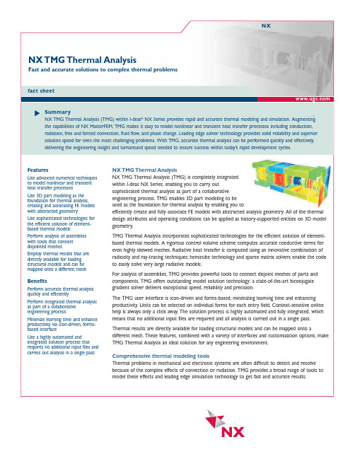
NX TMG Thermal Analysis NX TMG Thermal Analysis (TMG) is completely integrated within I-deas NX Series,enabling you to carry out sophisticated thermal analysis as part of a collaborative engineering process.TMG enables 3D part modeling to be used as the foundation for thermal analysis by enabling you to efficiently create and fully associate FE models with abstracted analysis geometry.All of the thermal design attributes and operating conditions can be applied as history-supported entities on 3D model geometry.TMG Thermal Analysis incorporates sophisticated technologies for the efficient solution of element-based thermal models.A rigorous control volume scheme computes accurate conductive terms for even highly skewed meshes.Radiative heat transfer is computed using an innovative combination of radiosity and ray-tracing techniques;hemicube technology and sparse matrix solvers enable the code to easily solve very large radiative models.For analysis of assemblies,TMG provides powerful tools to connect disjoint meshes of parts andcomponents.TMG offers outstanding model solution technology:a state-of-the-art biconjugategradient solver delivers exceptional speed,reliability and precision.The TMG user interface is icon-driven and forms-based,minimizing learning time and enhancingproductivity.Units can be selected on individual forms for each entry field.Context-sensitive onlinehelp is always only a click away.The solution process is highly automated and fully integrated,whichmeans that no additional input files are required and all analysis is carried out in a single pass.Thermal results are directly available for loading structural models and can be mapped onto adifferent mesh.These features,combined with a variety of interfaces and customization options,makeTMG Thermal Analysis an ideal solution for any engineering environment.Comprehensive thermal modeling toolsThermal problems in mechanical and electronic systems are often difficult to detect and resolvebecause of the complex effects of convection or radiation.TMG provides a broad range of tools tomodel these effects and leading edge simulation technology to get fast and accurate results.NX TMG Thermal AnalysisFast and accurate solutions to complex thermal problemsNXfact sheetFeaturesUse advanced numerical techniques to model nonlinear and transient heat transfer processesUse 3D part modeling as the foundation for thermal analysis,creating and associating FE models with abstracted geometryUse sophisticated technologies for the efficient solution of element-based thermal modelsPerform analysis of assemblies with tools that connect disjointed meshesEmploy thermal results that are directly available for loading structural models and can be mapped onto a different mesh Benefits Perform accurate thermal analysis quickly and efficiently Perform integrated thermal analysis as part of a collaborative engineering process Minimize learning time and enhance productivity via icon-driven,forms-based interface Use a highly automated and integrated solution process that requires no additional input files and carries out analysis in a single passSummaryNX TMG Thermal Analysis (TMG) within I-deas ®NX Series provides rapid and accurate thermal modeling and simulation.Augmenting the capabilities of NX MasterFEM,TMG makes it easy to model nonlinear and transient heat transfer processes including conduction,radiation,free and forced convection,fluid flow,and phase change.Leading edge solver technology provides solid reliability and superior solution speed for even the most challenging problems.With TMG,accurate thermal analysis can be performed quickly and effectively,delivering the engineering insight and turnaround speed needed to ensure success within today’s rapid development cycles.UGS,T eamcenter ,Solid Edge,Femap and I-deas are registered trademarks;and Imageware is a trademark of UGS Corp.All other logos,trademarks or service marks used herein are the property of their respective owners.Copyright ©2004 UGS Corp.All rights reserved.10/2004ContactUGSAmericas 800 498 5351Europe 44 1276 705170Asia-Pacific 852 2230 。
胡尔斯滚动控制安装说明说明书

WORK SAFELY! For maximum safety, perform this installation on a clean, level surface and with the engine turned off. Place blocks or wedges in front of and behind both rear wheels to prevent movement in either direction.CAUTION: To avoid any possibility of bodily injury or damage to vehicle, do not attempt installation until you are confident that the vehicle is safely secured and will not move.WARNING:The Hurst Roll Control is designed primarily for high performance race cars to momentarily (maximum of 60 seconds) keep the front brakes engaged while staging for a drag race. It will not safely function as a long term brake holding device. It should never be used as a temporary brake holding device in place of a parking brake or of a driver depressing the brake pedal. The Hurst Roll Control is recommended for use during closed track events and competitive driving venues ONLY! PARTSInstallation InstructionsHURST ROLL CONTROLFits: 2005-2009 Mustang V8Catalog# 5671521S. Steel Brake Line To Front Brake Line1/8 NPT plug (2)S. Steel Adapter (2)Solenoid Valve1/4-20 Nut (2)S. Steel Bracket1/4 Flat washer (2)S. Steel Brake Line ToMaster CylinderToolsBRAKE LINE INSTALLATIONRocker Switch Scotchlok™Conctr.Convoluted Cover5/16” Connectors (3)1. Identify the mounting location of the solenoid and the Master Cylinder front brake line within the engine compartment. 18 ga. WireMale Terminals (2)Butt Connectors (3) 4A Fuse FrontMaster Cylinder Front Brake LineFrontMounting Location2. Attach mounting bracket to solenoid as shown in step 2 and3. Add a few drops of Loctite ® (red) to bolt threads. Place one 1/4-20 bolt, 1/4” flat washer, 1/4” lockwasher, and 1/4-20 nut on each hole and fully tighten to 20Nm (15 ft-lbs). TOOLS: 7/16” Wrench, 7/16” Socket, Ratchet 3. Tighten the provided adapters and plugs to solenoid as shown.TOOLS: 16mm Wrench, 11mm Wrench NOTE: Use Teflon ® tape to ensure a leak-proof seal.CAUTION: Using an excessive amount of thread sealer can contaminate the solenoid valve or brake system. Use tape sparingly. If the solenoid body loosens while tightening adapters/plugs, first, make sure ports are correctly aligned and then use a 9/16”socket to re-tighten top solenoid nut. To Master Cylinder Solenoid NutPluggedTo Front Brake Line4. Ensure that the new brake line routing is understood prior to installation. However, DO NOT attach lines to solenoid at this time. NOTE: Using Teflon ® tape on flare fitting threads is generally not recommended. However, if used do not cover any portion of line opening with tape. To Master Cylinder To Front Brake Line5. Remove left Master Cylinder nut from Master Cylinder. TOOLS: 13mm Socket, Ratchet, Extension Master Cylinder NutFront6. Add clean rags under Master Cylinder in order to keep fluid from spilling on vehicle. Unscrew front brake line (Right- closest to driver). Remove front brake line from brake line clip, located on the side of the strut tower. TOOLS: 13mm Wrench, Clean rags NOTE: Avoid spilling brake fluid, especially on painted and/or plastic surfaces. Remove any and all excess brake fluid immediately with a clean rag. Front7. Move flex line from under Master Cylinder front brake line so it won’t prevent the Master Cylinder front brake line from screwing into the Hurst brake line. Unscrewing Master Cylinder rear brake line might be required to move flex line. FrontMaster Cylinder Rear Brake LineMove Flex Line to allow Master Cylinder Front Brake Line to Screw into Hurst Brake Line8. Recommended Installation Method: Thread the Hurst Roll Control brake line into the OEM front brake line, however do not completely tighten fitting at this time to allow for minor adjustments. Thread the Hurst Roll Control brake line into the adapter, finger tight. Push OEM brake line down to allow mounting bracket hole installation onto the Master Cylinder stud. (Slight adjustment (bending/flexing) of lines may be required for proper alignment). Once line is aligned, tighten all flare fittings.DO NOT OVER TIGHTEN AS THIS WILL CAUSE LEAKS.TOOLS: 13mm Wrench (Brake Line nut) 16mm Wrench (Adapter) Front9. Thread nut back onto master Cylinder stud, tighten Master Cylinder nut to 25Nm (18ft.-lbs). TOOLS: 13mm Socket, Ratchet, ExtensionWIRING INSTALLATIONNOTE: The Hurst Roll Control Solenoid Valve is designed for 12V DC operation only. For added safety, two switches (arming and activation) are provided in this kit. Following the wiring recommendation properly will prevent accidental engagement of the Hurst Roll Control system.Disconnect negative (-) battery terminal. If more wire is needed then what is provided, use #18 gauge standard insulated automotive wire to assure good electrical connection and conductivity. Wiring should be as neat and direct as possible. DO NOT connect wiring in such a fashion as to apply added stress or excessive stretch to wires. Use convoluted sleeve to protect wires, keep wiring away from sharp edges/corners, hot engine, and exhaust components. Join all splices by using the provided connectors/terminals and wrap each splice/connection with an adequate grade of electrical tape. A fuse holder with a 4-amp fuse is provided (See wiring diagrams for wiring details on page 10) and should be incorporated into the wiring circuit. The fuse can protect the electrical system in the event of a short circuit. 10. Recommended Installation Method: Thread the Hurst Roll Control brake line into the Master Cylinder, however do not completely tighten fitting at this time to allow for minor adjustments. Thread Hurst Roll Control brake line into the adapter, finger tight. (Slight adjustment (bending/flexing) of lines may be required for proper alignment). Once line is aligned, tighten all flare fittings. DO NOT OVER TIGHTEN AS THIS WILL CAUSE LEAKS. TOOLS: 13mm Wrench (Brake Line nut) 16mm Wrench (Adapter)Front11. BEFORE OPERATING VEHICLE:- Bleed ALL (back, then front on both sides) brakes by following manufacturer’s service manual guidelines (front brakes will usually have the most air).- Make sure all fittings are fully secured.- Verify no leaks are present, THERE SHOULD BE NO LEAKAGE. The brake pedal should be firm with a solid feel. If brake pedal slowly compresses to the floor, there is a brake fluid leak and/or air in system. Check and re-bleed if necessary. Do not operatevehicle if leaks and/or air in the lines is present nomatter how minor.New Line to Master Cylinder New Line to Front OEM Brake LineFront12. Suggested Solenoid Ground:Attach 5/16”eyelet connector to black wire of solenoidand ground wire to bolt on strut tower or anotherappropriate grounding location.TOOLS: 13mm Socket, Ratchet, Extension(See wiring diagrams on pages 8 and 9)GroundFront13. Pass wiring through existing access points (one is located on the driver’s side firewall) by going through the grommet of the hood latch release cable.Run wiring through here (inside of vehicle picture)14. Suggested 12V Source:Tap into a 12V accessory/cigarette lighter socket wiring harness connection with provided Scotchlok connector or another appropriate 12V source.(See wiring diagrams on pages 8 and 9) Scotchlok™ Connector12V Source15. Mount switches in desired location (usually within reach of the driver) and ground momentary switch to an appropriate grounding location with provided 5/16” eyelet.CAUTION: Before driving vehicle, completely check the brake system for proper operation. Check all connections under pressure for leaks and be sure that you have a good solid brake pedal (bleed brakes again to get a firmer brake pedal). On a flat level surface, Test the Roll Control system several times to be sure that it operates correctly. Be sure that the proper two wheels have the brakes engaged when the Roll Control is actuated and that all four wheels are free when the Roll Control switch is released.Basic Switch OperationSystem Arming: Turn on rocker switch, the momentary switch will light to indicate the Hurst Roll/Control system is ready or “hot”.Solenoid Engagement: Depress and hold momentary switch (Do not hold for more than 60 seconds).See “Hurst Roll Control Operation” for competition use.Caution: Holding the solenoid valve closed for more than 60 seconds can cause the fuse to burn-out, permanently damaging the solenoid valve, and/or result in other damage. De-activate (switch off) arming switch when the Hurst Roll Control is not in use to prevent accidental engagement.16. Reconnect battery and turn ignition switch to the “ON” position. While still in park and NOT depressing your brake pedal, activate and engage your Hurst Roll/ Control system (make sure you can hear the clicking of the solenoid) several times and check fuse. If fuse is burned, check all electrical connections for a short and correct any problems immediately.SwitchMomentary Engagement Switch17. Before executing a burnout, turn OFF your Traction Control (At a complete stop, press Traction Control button - “TCS OFF” dash light should appear to indicate Traction Control is off. Note: Turn ON your Traction Control / AdvanceTrac when not using the Hurst Roll Control.Warning: Performing a burnout without the Traction Control / AdvanceTrac off can damage the vehicle. Also,avoid excessive loading of the clutch, flywheel, and otherdrivetrain components. Traction ControlOPERATION INSTRUCTIONSTo actuate the Hurst Roll/Control system (BURNOUT):1. With the Traction Control System (TCS) OFF, fully depress and hold the brake pedal.2. Arm the Hurst Roll Control system by depressing the rocker (arm) switch to the “ON” position (the engage button switch should illuminate).The next steps should be complete within 60 seconds.3. Hold the illuminated button switch down and keep it held down until step 7 below.4. Release the brake pedal.The front brakes will now be locked and the rear wheels un-locked and free to spin.5. Automatic Vehicles- sharply step on the gas pedal.Manual Vehicles- raise the engine speed to a moderate level and smoothly but quickly release the clutch.The rear wheels should now be spinning and the vehicle should be stationary if the above steps have been performed correctly.6. Modulate the gas pedal to control the amount of wheel spin.7. Release the illuminated button switch and allow the vehicle to “drive-out” of the burnout.8. Be prepared to ease off on the gas pedal and press the brake pedal if necessary.9. Disarm the Hurst Roll Control system by depressing the rocker switch to the “OFF” position (the engage button switch should no longer be illuminated).10. Press the Traction Control System (TCS) button again and/or restart vehicle to turn on your Traction Control system.To actuate the Hurst Roll/Control system (LAUNCH CONTROL – Automatic Vehicles Only):1. With the vehicle staged fully, depress and hold the brake pedal.2. Arm the Hurst Roll Control system by depressing the rocker (arm) switch to the “ON” position (the engage button switch should illuminate).The next steps should be complete within 60 seconds.3. Hold the illuminated button switch down and keep it held down until step 6 below.4. Release the brake pedal.The front brakes will now be locked and the rear wheels un-locked and free to be loaded.5. Slowly and smoothly step on the gas pedal to load the torque converter and drivetrain just prior to wheel spin (this step may take some practice).6. GO! - Release the illuminated button switch and modulate the gas pedal as the light turns green/flag drops/etc. to hard launch the vehicle forward.7. Be prepared to ease off on the gas pedal and press the brake pedal if necessary.8. Disarm the Hurst Roll Control system by depressing the rocker switch to the “OFF” position (the engage button switch should no longer be illuminated).IMPORTANT: RETAIN THESE INSTRUCTIONS FOR FUTURE REFERENCETechnical ServiceA highly trained technical service department is maintained by Hurst Performance to answer your technical questions, provide additional product information and offer various recommendations. Technical service calls, correspondence, and warranty questions should be directed to:Hurst Performance Products(707) 544-4761 Wiring Diagram。
Massey Ferguson GC2400 GC2410 GC2600 GC2610

ContentsMassey Ferguson®GC2400 / GC2410 / GC2600 / GC2610Compact TractorWORKSHOP SERVICE MANUAL4283093M110 - ElectricalContentsELECTRICALWire Harness ................................................................................................................................................. 10-1 Electrical System ........................................................................................................................................... 10-3 Battery ..................................................................................................................................................... 10-3 Wiring/Fuse Arrangement ....................................................................................................................... 10-5 Neutral Starting Switches ........................................................................................................................ 10-6 Combination Switch ................................................................................................................................. 10-6 Main Switch ............................................................................................................................................. 10-6 Spare Power Supply ................................................................................................................................ 10-7 Wiring Diagram .............................................................................................................................................. 10-7 Electrical ...................................................................................................................................................... 10-11 Safety Switches, Fuses and Relays ...................................................................................................... 10-11 Fuel Shut Off Solenoid .......................................................................................................................... 10-13 Oil Pressure Sending Unit ..................................................................................................................... 10-13 Water Temperature Sending Unit .......................................................................................................... 10-14 Fuel gauge Sending Unit ....................................................................................................................... 10-14 Instrument Panel .......................................................................................................................................... 10-15IN DEX ............................................................................................................................................................. 10-17ContentsNOTESElectricalELECTRICALWIRE HARNESSFIG. 1:Wiring harness layout for chassis.(1)Battery (2)Fuel Pump (3)Main Harness Earth (4)PTO Switch (5)Power Outlet(6)Rear Combination Lamp (7)Head Lamp (8)Neutral Switch (9)Fuses and RelaysFIG. 1I-120021324567298ElectricalFIG. 2:Wiring harness layout for engine.(1)Flashing Warning Light Switch(2)Slow Blow Fuse (L: For Main Circuit (40A))(R: For Alternator (40A))(3)Alternator B T erminal (4)Alternator L and R T erminal (5)Starter B T erminal (6)Main Switch (7)Flasher(8)Engine Safety Switch (9)T urn Signal Light Switch(10)Key Stop Relay (11)T urn Signal Light Relay (12)Engine Safety Relay (13)Engine Glow Plugs (14)T emperature Sender (15)Oil Pressure Switch (16)Key Stop SolenoidFIG. 2I-1200321679810111254313141615Electrical ELECTRICAL SYSTEMBatteryFIG. 3:The battery (1) is located under the engine hoodin front of the instrument panel. When battery removal,electrolyte inspection, or cable cleaning is required, openthe engine hood.Keep top of battery clean and make sure cableconnections are clean and tight. Debris on battery cancause discharge of battery and possible fire.m CAUTIO N:Batteries produce explosivehydrogen gas when charged. Keep allsparks and open flame away from battery.When necessary to disconnect batterycables, always disconnect the grounded (-)cable first to prevent short circuits.Batteries contain sulfuric acid electrolyte(fluid). Wear eye and face protection. Ifelectrolyte comes in contact with skin orclothes, wash immediately. Contactphysician if electrolyte is ingested or getsin eyes.FIG. 4:If battery replacement is necessary, disconnect negative (-) cable (1) first and then remove positive (+) cable (2). Loosen and remove battery securing clamp and carefully remove battery from tractor.When installing battery, connect cable (2) connected to starter solenoid to positive (+) battery terminal first. Then connect cable (1) grounded to tractor frame to negative (-) battery terminal.IMPORTANT:Do not reverse battery cable connections as severe electrical system damage will result. NOTE:Make sure replacement battery is of the same size and equal capacity.NOTE:Water does not need to be added to battery. The battery is a maintenance-free type battery. Never close or cover vent of battery. FIG. 31I-11215 FIG. 412I-8040ElectricalFIG. 5:Battery indicator (1) color shows battery condition. When checking battery, park machine on a level surface and check the indicator at top of battery.If indicator shows clear or light green color, tap battery body to remove bubble inside indicator.m WAR N I N G:N ever disassemble battery.Batteries contains sulfuric acid electrolyte(fluid). Keep away from sparks or flames,which could cause explosion.When charging battery from an externalsource, set charging voltage below 16V. Setcharging ampere below 1/10 (one tenth) ofbattery capacity.When connecting and disconnectingbattery cables, turn off power of batterycharger. If you have any questions aboutthe battery, consult your dealer.If battery performance is low, remove battery and charge from an external supply following battery charger instructions. Repeated battery charging can be because of a defect in tractor charging system and/or a defective battery.NOTE:When charging battery from an external supply, battery temperature must not be more than54degrees C (125 degrees F). If batterybecomes too hot, charge rate must be reducedor stopped.FIG. 51I-8032Indicator Color Condition Correction Green Charged UsableBlack Discharged Charge batteryClear Low Electrolyte Replace batteryElectricalWiring/Fuse Arrangementm CAUTION:Keep all wiring connectionsclean and tight. Make sure wiring iscorrectly secured to prevent damage.m CAUTION:DO N OT alter wiring by addinghome-made extensions or replacements.Doing so can eliminate fuse protectionand/or eliminate safety features of thesystem.m CAUTIO N:Tractor is equipped withnegative (-) ground system. Tractor metalparts provide many electrical connections.For this reason, all positive (+) circuits mustbe insulated to prevent grounding or shortcircuits and prevent possible fire.m CAUTION:DO NOT replace any fuse with afuse of higher amperage rating. DO N OTuse wire (or foil) to by-pass fuse protection.Fire can result.If fuses blow repeatedly, examine electricalsystem for grounded or shorted circuits.FIG. 6:Main fuse box (1) - Located on right-hand side atthe rear of the engine.Slow blow fuses (2) are located above and to the right ofbattery. Slow blow fuses are inline fuses that protect acircuit by melting when sustained heavy electrical load orshort circuit is found. Slow blow fuses give a delayedaction to prevent current break when short surges arefound.IMPORTANT:Fuses are of specific amperage for thecircuit. Do not replace fuses with unauthorizedparts.NOTE:Failure of alternator circuit slow blow fuse isnormally caused from not correct polarity (suchas reversed cables when using a boosterbattery). A failed fuse will not let battery becharged during normal operation.FIG. 7:Main fuse box components:Slow blow fuses:(6) A 40A slow blow fuse is green and protects the main circuit.(7) A 40A slow blow fuse is green and protects the alternator circuit.FIG. 621I-11215 FIG. 7I-11216 6712345Ref Amp Function115A Turn signals210A Headlamp, tail lamps35A Engine stop415A Power outlet (accessory) 510A Instrument panelElectricalNeutral Starting SwitchesThis tractor is equipped with a neutral-start system consisting of neutral switches and a relay. T o start the tractor, ALL the following is required:•Range shift lever must be in neutral position.•PTO control lever must be OFF .mWARN IN G:DO N OT bypass or modify the neutral switch. If the neutral start system does not operate properly, consult your Dealer immediately.Combination SwitchFIG. 8:Combination switch diagram.Main SwitchFIG. 9:Main switch diagram.FIG. 8I-11182Combination Switch B1B2R L T 1Light Switch OFF 1Turn Signal SwitchL OFF RFIG. 9I-11178Main Switch BAC G STOFF ON GLOW ST ARTElectrical Spare Power SupplyFIG. 10:Located at the rear of the tractor to the left-handside of the top link is a spare power supply receptacle (1).Use a male bullet connector 4 mm (0.156in) with0.85mm2 (18 ga) wire size. See item 19 in Fig. 12.WIRING DIAGRAMFIG. 11:This illustration shows a wiring legend for schematics on the following pages.(1)Wire size(2)Wire color code(3)Ground FIG. 10I-112371FIG. 110.5 RY123WireColorCode Wire Color WireColorCode Wire ColorW White YR Y ellow/Red B Black WR White/RedR Red WB White/Black Y Y ellow WY White/Y ellow G Green WL White/Blue L Blue BR Black/RedBr Brown RY Red/Y ellow Lg Light green WG White/Green O Orange YB Y ellow/Black P Pink GB Green/Black Gr Gray GR Green/Red Sb Sky Blue GY Green/Y ellow RW Red/White GW Green/White BY Black/Y ellowElectricalThe following information refers to Fig. 12:(1)Engine Stop Solenoid(2)Fuel Pump - 12V 1.5A(3)Glow Plugs(4)Hazard Switch(5)Water T emperature Sensor(6)Oil Pressure Sensor(7)Flasher Unit (SAE)(8)T ail Light Relay (normal open type)(8a)Left-hand(8b)Right-hand(9)Fuel Gauge(10)Fuel Meter(11)Instrument Panel with Monitor(12)Left T urn Signal Display Lamp(13)Right T urn Signal Display Lamp(14)Oil Pressure Display Lamp (3.4W)(15)Battery Charge Display Lamp (3.4W)(16)Right-Hand T urn Signal Lamp - 12V 21W x 2(17)Right-Hand T ail Lamp - 12V 5W / 21W(18)Seat Switch (with cushion seat assembly)(19)Spare Power Supply - capacity less than 70W(20)Left-Hand T urn Signal Lamp - 12V 21W x 2(21)Left-Hand T ail Lamp - 12V 5W 21W(22)Safety Switch (PTO clutch lever)(23)Safety Switch (sub change)(24)Starter Relay (normal open type)(25)Diode - 3A(26)Main Switch(27)Combination Switch -Lamp 12V 100W, Blinker 12V 60W(28)Fuse Box(29)Engine Stop Relay(30)Slow Blow Fuse - 40A(31)Starter Motor - 12V 1.1 kw(32)Slow Blow Fuse - 40A(33)Alternator - 12V 40A(34)Left-Hand Head Lamp - 12V 13W x 2(35)Right-Hand Head Lamp - 12V 13W x 2(36)Battery - 55824R/S 433 ccaFIG. 1233311178b8a12253569262417281618192521i-9388aI-112173630324827202334291213151432Electrical10–9ElectricalThis Page Intentionally Blank 10–10Electrical ELECTRICALSafety Switches, Fuses and RelaysFIG. 13:The fuse panel (1) is located to the right of thebattery.FIG. 14:The slow blow fuses (1) that protect the starter circuit and charging circuit are located on the wire harness to the right of the battery.FIG. 15:The seat switch (1) is located under the seat.FIG. 131P205744 FIG. 141P205744 FIG. 151P2057654283093M1 10-11Electrical10-124283093M1FIG. 16:The PTO Switch (1) is located on the LH side at the base of the PTO shift linkage.FIG. 17:The neutral start switch (1) is located below the base of the range lever on the RH side.FIG. 18:The LH red flasher relay (1) the RH red flasher relay (2) is mounted on the RH side of the steering column.The Fuel Shut Off relay (3) and Hazard/T urn Signal relay(4) for the amber lights on the fender are mounted on the RH side of the steering column. The Fuel Shut Off relay energizes the fuel shut off solenoid for approximately ten seconds after the key is turned off.The safety start relay (5) is located on the RH side of the steering column. The safety relay will not let the engine start if the PTO is engaged or the range lever is in gear.The safety relay will also shut the engine OFF if the PTO is engaged or the range lever is engaged and the operator is not sitting in the seat.FIG. 16P2057701FIG. 17P2191261FIG. 184P3127561523Electrical FIG. 19:The diode (1) is located In front of the steeringcolumn behind the battery.Fuel Shut Off SolenoidFIG. 20:The Fuel Shut Off relay energizes the fuel shut off solenoid (1) for approximately ten seconds after the key is turned OFF. When the solenoid is energized, the flow of fuel to the engine is turned OFF. The fuel shut off solenoid is located on the injection pump. The fuel can also be shut off manually by pressing in on the rubber boot (2) at the end of the fuel shut off solenoid.Oil Pressure Sending UnitFIG. 21:The oil pressure sending unit (1) is located on the LH side of the engine. The oil pressure light will turn on when the engine oil pressure drops below 68 kPa (10 psi). Tighten the sending unit 8 - 14 ft-lbs.FIG. 191P312798 FIG. 20ka10048 12FIG. 21ka1005114283093M1 10-13。
燃烧炉CF-2用户和维护手册说明书

BURN-OUT FURNACECF-2USER AND MAINTENANCE MANUAL1 – GENERAL INFORMATION1.1 – PURPOSE OF THE MANUALThis instruction manual is an integral part of the machine and must follow it whenever it is moved. The manual must be kept carefully during the machine lifetime and must in all cases be available for at least 10 years, it must therefore be stored in a known location and be made available to all the personnel concerned.Do not connect or start up the furnace before reading through this manual.1.2 – TECHNICAL INFORMATIONCF-2 is managed and operated by a microprocessor control and has been designed to heat up investments used in the Dental and Jewellery labs.CF-2 can operate with 2 heating cycles (or programs): a fast program and a normal program. Both are stored in memory as long as the user decides to modify them. The Normal program can consist of up to three stages, and for each of them the following parameters can be set: temperature, gradient, stabilization time.Also, the following functions are available:- delayed startup of the unit (scheduling up to 100h from setting)- temperature stabilization time at the end of the cycle.SymbolsA Muffle D Refractory chamberB Electronic control E Power supply 220/240V – 50/60HzC Door F Fume exhaust (optional)1.3 – SAFETY DEVICEElectronically fed parts are shielded by means of fixed protective coverings to prevent anyaccess by the operator. Access to these parts is allowed only to skilled and authorizedtechnician, properly trained about extraordinary maintenance and repair operations.1.4 – TECHNICAL REFERENCES AND WASTE DISPOSALAccording to International regulations, this unit has been classified as AEE(electric and electronic device, whose correct operation depends on electriccurrents and electromagnetic fields) and as a consequence, at the end of itslifetime, it can not be treated as normal waste material but it must be disposedseparately, complying with the Directive 2002/96/CE.1.5 – TECHNICAL FEATURESCF-2 S CF-2 M CF-2 LTension Frequency 230V-50/60Hz 230V - 50/60Hz 230V - 50/60HzHeating resistances 1600W 2200W 2800WMax Temperature 1100°C 1100°C 1100°CChamber dimensions mm 150 x 150 x 100180 x 230 x 115 230 x 300 x 150External dimensions LxWxH mm 320 x 400 x 470360 x 460 x 490 420 x 530 x 520Weight – Kg 32 37 49Number of programs 2 2 2Number of Normal programs 1 1 1Number of Fast programs 1 1 1Number of stages - Normal Program 3 3 3Delayed start - up to 100 hours Si Si Si16A Fuses 16A16A2 – HANDLING AND INSTALLATION2.1 – PACKING AND UNPACKINGPacking consists of polyurethane foam, polyethylene sheet, rigid carton cover and nylonprotection.Disposal of the packing materials is subject to local regulations and must be carried outconsidering the environment.2.2 – LOADING AND UNLOADINGThis machine must be moved by means of trolleys or manually by at least 2 people. Whilemoving the machine avoid absolutely any kind of bumping, dropping or tilting: they couldseriously damage it. In any case, the manufacturer is not responsible for damages causedby droppings, improper use and maintenance which are not strictly in accordance with themanufacturer’s instructions illustrated in this manual.2.3 - INSTALLATIONThe machine must be located on a safe place and in horizontal position. It is up to the user to ensure that the electric network is in accordance with the safety regulations in force.It is particular important to make sure that the grounding connection works properly. Furthermore, it is important to verify the network voltage: in case the voltage is too low (lower than 210V), this could lead to inconveniences and it might be necessary to install a voltage stabilizer.After having placed the furnace and gone through the above checklist, follow these instructions:• The general switch must be in the OFF (0) position.• Use the supplied cable to connect the power supply plug to a 220-230 V AC outlet.• Plug the vacuum pump cable into the corresponding socket.3 – INFORMATION FOR USE3.1 - PANELThe panel consists of the following elements:1 – LCD display: showig times and temperatures2 - SET UP keys: (¿ and À) to modify parameters or to select cycles3 – three-function START / STOP / ENTER key: this key activates a program (START)starting from the stand-by position; similarly, it ends a program whenever this is in use (STOP), or confirms shown values (ENTER).3.2 – PERFORMANCE AND USECF-2 can operate under two programming modes (P1 “Normal program” and P2 “Fast program”) which keep stored in a permanent memory till their modification. Program P1 can consist of up to 3 stages, i.e. it can be adjusted to have a maximum number of stages equal to 3 (it is always possible to set cycles with less than 3 stages). For each stage, the following parameters can be set: target temperature, gradient and temperature holding time. It is also possible to set a scheduled start time. Also, a stabilization time at the end of the cycle (F) can be set to preserve the casting rings at the correct temperature and to give the operator time to prepare for the forthcoming work.3.3 – START“STAND- BY” display:P1 or P2 on the left part of the display indicate the last modified program. On the right side, the internal temperature is shown.3.4 – PROGRAM SETTINGSBy using the arrows (¿ or À) you can switch from one program to another from P1 to P2 and vice-versa.A – Normal Program P1 (for traditional investments)In STAND-BY choose P1.To start programming, PRESS both arrows¿ and À SIMULTANEOUSLY:Choose the number of available stages: 1 or 2 or 3.Confirm by ENTER; in this case the cycle will have 3 stages. The following screen is:Set by ¿ and À the temperature T1 of the first stage, then confirm by ENTERSet gradient V1 in °C/min, confirm by ENTERDefine temperature holding time t1 of the first stage, set hours and confirm by ENTER, set minutes and confirm by ENTER. Proceed similarly for the next stages. After setting the temperature holding time for the last stage, when confirming by ENTER, the following screen will be shown:The F parameter is the additional time for temperature holding at the end of the cycle. This is an extra time to allow burning in case of more rings, or should the operator neither be present nor ready. Their value is expressed in hours, minimum is 1 hour. By pressing ENTER the user goes back to STAND-BY screen.B – Fast Program P2 (for quick investments)In STAND BY choose P2.To start programming, PRESS both arrows¿ and À at the same time:Set Temperature T then confirm by ENTER:Set gradient V in °C/min, then confirm by ENTER:Set temperature holding time t: set hours, confim by ENTER set minutes, confirm by ENTERSet the temperature holding time for the final temperature (during this time, sub-cycles specific for any casting ring can be set), then confirm by ENTER and return to STAND-BY screen.3.5 – EXECUTION OF A PROGRAMA – Carrying out normal program P1Proceed as follows:From STAND-BY position, select program P1 then press START/STOP and the following display will appear:At this stage, scheduled delayed time(in hours and minutes) can be inserted. To start immediately, confirm by ENTER the 0 value. To schedule a switch-on time, insert by means of the arrows both parameters and confirm by ENTER. The display shows a countdown to cycle start, when this will be 0 the furnace will start.IMPORTANT NOTICE: to set a schedule switch-on time, the remaining time to the cycle start will be considered. So, if the work has to be ready for the following day at 8:00am supposing it is 6:00pm , considering the fact that a cycle lasts about 1.30 hours, we will have to program the furnace to start at 6:30am, i.e. we will have to insert a delay of 12 hours and 30 minutes.When the furnace switches on (immediately when pressing last ENTER key, or after the remaining time has expired) the following screen will appear:The lines on the left part represent the burning cycle graph: during raise in temperature, the curved portion will blink; on the right part of the display the target temperature is shown; in the middle, the detected temperature is shown. During stabilization stages, the horizontal portion of the graph will blink. In the middle of the display, the remaining timewill be shown, while on the right side the actual temperature is displayed.B – Start of P2 fast programSet P2 and execute the same procedure as for P1.When the desired burning temperature has been attained, the furnace enters into stabilization stage showing the following display:At this stage, burning sub-cycles can be activated. These will be started automatically by opening the furnace door while inserting rings of quick investment. This action initiates a timer control, while the display shows editable values. Put the casting ring into the furnace, close the door, correct the shown values by means of the arrows and press START: the furnace will calculate the remaining time, at the end of which a buzzer will warn the user. At this stage, the casting ring can be taken out and eventually replaced with a new one, thus restarting the same burning program as a sub-cycle, correcting or confirming times by means of the ENTER key. During the whole stage, the temperature will remain unaltered. The furnace switches off automatically after the final stabilization time or can be switched off by pressing and holding for at least two seconds the START/STOP key.3.6 – CHIMNEY FANThis furnace can support the A1211 fume exhaust extractor.In P1, the chimney fan starts at the beginning of the cycle and switches off at 400°C. In P2, the chimney fan starts at the beginning of the sub-cycles and keeps operating for their entire duration.4 – MAINTENANCE INFORMATION4.1 – ORDINARY CLEANING AND MAINTENANCEIt is recommended to clean the firing chamber from the residues left by wax combustion. These can cause the deposits to sediment which might be detrimental to the correct functioning of door springs and joints. Utilize a humid tissue and do not switch on the furnace before it is completely dry. All cleaning operations are to be performed when the unit is OFF and disconnected from the power network.To clean the furnace do not use diluting agents, petrol, or other inflammable liquids or corrosive agents: these could damage external varnish and be absorbed by the refractory materials, thus originating toxic gases when switching on the furnace. Besides the considerations stated above, the unit does not require any further maintenance operations.4.2 – EXTRAORDINARY MAINTENANCEFor parts replacement or repair, contact qualified and well-trained technical staff only.Do not open protections on the machine without undertaking all necessary precautions. Before any operation disconnect the unit from power supply.5.0 – WIRING DIAGRAMPOS. DESCRIPTIONF 16 Amp.FUSEIG MAIN SWITCHC.B. CONTROL BOARDKEY KEYBOARDDIS DISPLAY BOARDRES RESISTANCET/C TERMOCOUPLEMS DOOR MICROSWITCHP OUT SOCKET FOR FUME EXTRACTORFAN COOLING FAN6.0 – EXPLODED DRAWING AND SPARE PART LISTN° CF-2 S CF-2 M CF-2 L DESCRIPTIONWax collection plate1 4014S005 4014M005 4014L005Lower secondary insulation panel2 4014S015 4014M015 4014L015Lower primary insulation panel3 4014S011 4014M011 4014L011Side secondary insulation panel4 4014S017 4014M017 4014L017Side primary insulation panel5 4014S013 4014M013 4014L0136 4014S012 4014M012 4014L012Upper primary insulation panelUpper secondary insulation panel7 4014S016 4014M016 4014L0168 4014S014 4014M014 4014L014Rear primary insulation panelRear secondary insulation panel9 4014S018 4014M018 4014L01810 4014SR007 4014MR007 4014LR007Heating chamber compl. with resistance11 4014021 Heating chamber compartment plate12 4014030 Insulating bush for resistance13 4014107 Chimney pipe14 4014022 Rear panel15 4014109 Thermocouple fixing spring16 4014003 Thermocouple17 4014032 Ceramic terminal block for resistance18 4014031 Insulating bush for thermocouple19 4014033 Spacer20 4014110 Socket for fume extractor21 4014026 Equipment case rear panel22 4014114 Fan grate23 4014113 Cooling fan24 4014100 Cable locking ring25 4014101 Feeding cable26 4014115 16A fuse27 4014102 Fuse holder28 4014103 Main switch29 4014025 Equipment case30 4014111 Rubber foot31 4014050 Electronic card set32 4014027 Control panel33 4014002 Polycarbonate panel- 4014001 Electronic control board complete (31-32-33)34 4014105 Microswitch spring35 4014104 Door microswitch36 4014028 Microswitch case37 4014023 Sheet metal door38 4014106 Door handle39 4014108 Door hingeDoor refractory40 4014S004 4014M004 4014L00441 4014024 Frame for refractory door42 4014009 Front closing panel43 4014020 Front refractory support44 4014S006 4014M006 4014L006Front refractory plate45 4014008 Heating chamber caseDENTALFARM S.r.l.Via Susa, 9/a - 10138 TORINO - ITALY tel. (+39) 011 43465588 - 4346632fax (+39) 011 4346366************************www.dentalfarm.it。
M93R II NS2 操作手册说明书

®OPERATOR’S MANUALM93R II NS2M93R II NS2TABLE OF CONTENTSUse of this manual (2)Safety Guidelines ........................................................................................2-3 Warranty and Service ..................................................................................4-5 Specifications .. (6)Contents (7)Functions and Features (7)Charging Gas (8)BB Loading (9)Loading Magazine (10)Cocking (10)Safety (10)Shooting (11)Shooting Modes (11)Open Slide (12)After Shooting (12)Hop-Up System (13)Hop-Up Adjustment Point (14)Disassembly (15)Assembly (16)Troubleshooting (17)General Maintenance (18)Operating Under Unusual Conditions (18)Diagrams and Parts Lists .......................................................................19-22 1USE OF THIS MANUAL Before operating the Airsoft gun, read this manual in its entirety. Important safety topics and tips are discussed throughout all of the chapters. It’s important that the operator know the principles of gun handling safety and operation prior to firing the Airsoft gun.SAFETY GUIDELINESWARNING! Failure to follow safety guidelines may result in serious injury.Safety Distance The effective shooting range is approximately 75 feet. BBs fired from this Airsoft gun may travel further than intended. Make certain that you have an adequate backstop.Eye Protection Eye protection should be worn at all times when both shooting and maintaining your Airsoft gun. Protect your eyes from silicone spray and BBs under spring pressure while performing maintenance on your Airsoft gun.Assume Every Gun is Always Loaded Until you are certain the chamber is empty, treat every gun as if it were loaded. Do not assume the chamber is empty based on your memory or someone else’s words. Always remove the magazine and visually check to confirm the chamber is empty.Beware of Barrel Obstructions Ensure the Airsoft gun barrel is free of obstructions before you fire the gun. Even the smallest obstruction such as lubrication or a stuck cleaning patch can cause a misfire or malfunction.Muzzle Control Always keep the muzzle of the gun pointed in a safe direction. Never point the muzzle at a person or object that you do not intend to shoot.Keep Your Safety On Keep the gun’s safety on until your sights are aligned on your target and you are ready to fire.Keep Your Finger Off The Trigger Keep your finger off the trigger and out of the trigger guard until your sights are aligned on your target and you are ready to fire.WARNING! Airsoft BBs can be a choking hazard. Keep them away from children.!!2M93R II NS2SAFETY GUIDELINESIdentify Your Target and BackstopBefore you pull the trigger, make certain of your target and what is beyond it. The Airsoft gun should never be fired at surfaces such as rocks, glass, water, or other hard surfaces where BBs are likely to ricochet in unpredictable directions.WARNING! Adult supervision is required for any person!under the age of 18.Failure To FireIf the Airsoft gun fails to fire, misfires, or malfunctions, do not look into the gun barrel. BBs can become lodged into the chamber, and serious eye injury may occur.Maintain Your Gun ProperlyPerforming proper maintenance, as outlined in this manual, ensures that your Airsoft gun will be safe to shoot and will perform to its designed specifications for many years. Alterations, modifications or adjustments may damage your Airsoft gun, make it unsafe to shoot, and will void all warranty claims.Store Your Gun SafelyAlways store the Airsoft gun in a safe place, and out of the reach of children. Always transport the Airsoft gun in a carrying case. Never display the Airsoft gun in a public place. Keep the safety engaged, and remove the magazine before storing the Airsoft gun. Note: it is your responsibility to take every reasonable precaution to ensure the safe storage and transportation of your Airsoft gun.Orange TipThe orange tip on Airsoft guns helps Law Enforcement distinguish between the replica guns from their real firearm counterparts. Altering the coloration or markings required by state or Federal law so as to make the product look more like a firearm is dangerous and may be a crime. Operator assumes all risks and responsibility when doing so. Hazards of Being Mistaken for a Real FirearmAirsoft guns have been mistaken by Police and Law Enforcement as real firearms. A confrontation with law enforcement while carrying an Airsoft gun can result in serious injury or even death. It is strongly advised to operate the Airsoft gun at a safe and legal location. In the event that you are approached by Law Enforcement personnel, you must comply with their instructions immediately to avoid an incident.Alcohol, Medications and DrugsDo not handle or operate your Airsoft gun while under the influence of alcohol, medication or drugs.Your ResponsibilityYour Airsoft gun is well-engineered and manufactured to the highest standards. It was carefully inspected before it was packaged and shipped from our factory. Its safe use depends on you alone. You are the ultimate safety device. Like many other devices, your Airsoft gun is safe unless handled in an irresponsible or uneducated manner.3WARRANTY AND SERVICEKWA Performance Industries, Inc. is committed to serve our customers with the finest quality products, the highest level of service, and customer satisfaction. Because of this, we offer a 45-day warranty on all KWA products we import and distribute.What is CoveredExcept as specified below, this warranty covers all defects in material and workmanship in KWA products occurring during the above warranty periods. The following are not covered by the warranty: (1) Any product which is not imported and distributed in the U.S.A. by KWA PErfOrMANcE INDUSTrIES, INc. (2) Any products not purchased in the U.S.A. from an KWA AUTHOrIZED rESELLEr (Note: KWA AUTHOrIZED rESELLEr can be identified by KWA AUTHORIZED RESELLER sticker displayed in the store. If you are uncertain as to whether a dealer is a KWA AUTHOrIZED rESELLEr, please contact KWA PErfOrMANcE INDUSTrIES, INc. as listed above). (3) Damaged deterioration or malfunction resulting from: a) Accident, act of nature, abuse, misuse, neglect, unauthorized product repair, opening of or modification or failure to follow instructions supplied with the product. b) repair or attempted repair by anyone not authorized by KWA PErfOrMANcE INDUSTrIES, INc. c) removal of the orange safety tip. (4) Use of the product outside the U.S.A. (5) Damaged batteries or improper use of bullets (BBs), or non approved propellants (ie. Propane, red Gas, 134a…etc.) (6) Use in industrial, commercial, and/or professional applications.What KWA Will Pay ForIf during the applicable warranty period from the date of the original purchase your KWA product is found to be defective by KWA Performance Industries, Inc., KWA Performance Industries, Inc. will repair, or at its option, replace with new, used, or equivalent model, the defective product without charge for parts or labor.How To Obtain Warranty ServiceIf your product needs service, it may be taken or shipped to KWA Performance Industries, Inc. The following procedures apply whenever your unit must be transported for warranty service:• You must go to Help Desk at /support to obtain an RMA number.THE rMA NUMBEr MUST BE cLEArLY MArKED ON THE OUTSIDE Of THE PAcKAGE. PAcKAGES WITHOUT AN rMA NUMBEr cLEArLY MArKED WILL BE rEfUSED AND rETUrNED TO THE SENDEr.• You are responsible for transporting your unit or arranging for its transportation.• If shipment of your unit is required; you must pay the initial shipping fee, but we will pay the return shipping charge if the repairs are covered by the warranty.• WHEN RETURNING YOUR UNIT FOR WARRANTY SERVICE, A COPY OF THE OrIGINAL SALES rEcEIPT MUST BE ATTAcHED.• You must include the following: RMA number, your name, address, daytime telephone number, model and serial number (if applicable) of the product and a description of the problem.4M93R II NS2NOTE: THE rMA NUMBEr MUST BE cLEArLY MArKED ON THE OUTSIDE Of THE PAcKAGE. PAcKAGES WITHOUT AN rMA NUMBEr cLEArLY MArKED WILL BE rEfUSED AND rETUrNED TO SENDEr. NO EXcEPTIONS.This Warranty is Only Valid in the United StatesIf your product does not require service, but you have questions regarding its operation, please contact our Technical Services Department as listed below.THIS WArrANTY IS EXPrESSLY MADE IN LIEU Of ALL OTHEr WArrANTIES, EXPrESSED Or IMPLIED, INcLUDING WITHOUT LIMITATION, WArrANTIES Of MErcHANTABILITY AND fITNESS fOr A PArTIcULAr PUrPOSE.OUr LIABILITY IS LIMITED TO THE rEPAIr Or rEPLAcEMENT, AT OUr OPTION, OF ANY DEFECTIVE PRODUCT AND SHALL IN NO EVENT INCLUDE INCIDENTAL OR cONSEQUENTIAL cOMMErcIAL Or PrOPErTY DAMAGES Of ANY KIND. WE ArE NOT rESPONSIBLE fOr PrODUcTS LOST, STOLEN AND/Or DAMAGED DUrING SHIPPING.SOME STATES DO NOT ALLOW LIMITATIONS ON HOW LONG AND IMPLIED WArrANTY LASTS AND/Or DO NOT ALLOW THE EXcLUSION Of INcIDENTAL Or cONSEQUENTIAL DAMAGES, THE ABOVE LIMITATIONS AND EXCLUSIONS MAY NOT APPLY TO YOU. This warranty gives you specific legal rights, but you may also have other rights which vary from state to state. This Warranty may not be altered other than in writing signed by an officer of KWA Performance Industries, Inc.KWA Performance Industries, Inc.18571 E. Gale Ave.city of Industry, cA 91748-1339626-581-17775SPECIFICATIONS• Slide Material = Metal Alloy• Frame Material = Composite Polymer• Outer Barrel = High Impact Polymer• Hop-Up = Adjustable• Action = Double with selective fire (semi- auto, three round burst)• Propellant = Green Gas• Overall Length = 25.3 cm (9.96”)• Overall Height = 17.5 cm (6.89”)• Inner Barrel Length = 125 mm• Inner Barrel Diameter = 6.05 mm• Weight = 1.06 kg (2.34 lbs)• Caliber = 6 mm• Magazine Capacity = 32 (48)• Velocity = 104-107 MPS (340-350 FPS)• Energy Output with .20g BB = 1.07 Joules• Gas System = NS2• Available Colors = Black onlySpecial Features:• Functional decoking safety• Selective Fire (Semi-Auto, Three Round)• Integrated flip down front handle• Realistic construction and field stripping*Individual test results may vary depending on brand of BBs, type of gas, andchronograph used.6M93R II NS2CONTENTSProduct Package Contents1 M93r II NS2 Airsoft gun1 Bottle of Silicone Oil1 Hi-cap Magazine1 Sample bag of Airsoft BBs1 Hop-Up Adjustment Tool1 Operator’s ManualFUNCTIONS AND FEATURESM93R II with NS2 gas systemThe famous M93r is equipped with the new KWA NS2 internal gas delivery system, which increases performance and improves the overall reliability of the gun.The NS2 gas system is a KWA-patented design that uses an advanced, light-weight composite gas piston with a two-stage internal expansion chamber that delivers the gas more efficiently than that of its predecessors. The NS2 design also increases the weapon cycle rate and provides for a crisp, realistic blow-back actionOther parts of the Airsoft gun, including the recoil springs, recoil spring guide assembly, hop-up chamber, and magazine follower, have been improved, along with a new magazine that is milled from a solid alloy steel billet. This new construction strengthens the magazine’s structural integrity and increases pressure carrying capacity. The magazine feed-lip has also been reinforced.7CHARGING GAS1. release the magazine by pressing the magazine release button.2. Push the gas canister nozzle into the charging valve. Make sure the canister is ina vertical position when charging.3. Charge the magazine until gas overflows from the charging valve.!WARNING: Sudden impact with a hard surface may causedamage to the magazine.Note: It is normal to have minor leaking from the charging valve during charging due to high pressure built up inside the magazine. It is recommended to keep the gas release valve slightly oiled. room temperature is the ideal temperature for shooting. You may experiencea delayed action if the surrounding temperature drops below 68º f.Green Gas safety tips:• Check the canister for any cracks or leaks before using.• Do not expose the canister to temperature over 104º F.• Do not leave the canister directly over fire.• Do not heat the canister.• Keep the canister away from direct sunlight.• Do not leave the canister in any type of vehicle.8LOADING BBs1. Pull the magazine follower down until it locks.2. Insert BBs into the magazine lip.3. BBs should stack staggered for maximum round capacity: 48 rounds.4. Make sure to have a 3mm clearance between BBs and the top lip of themagazine.5. Push the magazine follower lock to release.Note: Always use KWA Perfect BBs, size 0.2 or 0.25g. Using only KWA Perfect BBs can give your Airsoft gun its best performance. Using recycled and low grade BBs may damage the gun.WARNING: Do not release the magazine follower when the magazine is empty. Doing so will damage the magazine and magazine follower.!39Pull the slide to the rear-most position and release the slide. This will automatically load the BBs into the chamber. The hammer will be in a cocked position. Make sure not to skip this procedure. Skipping this step will cause a misfire on the first pull of the trigger. The slide will stay open when the last BB is fired and ejected.10SHOOTING1. release the safety and pull the trigger. The blow-back action will load the BBsautomatically as the slide cycles back and forth.2. Grasp the Airsoft gun firmly in your hand. To properly control the gun, grasp it witha two-hand hold with one hand wrapped around the other.SHOOTING MODESWARNING: Never shoot gun in a horizontal or upside-down position.!M93R II NS2OPEN SLIDEThe slide will remain open after the last BB has been fired and ejected. Remove the empty magazine and replace it with a loaded magazine, then release the slide stop. The first BB will be automatically loaded into the chamber.Note: It is important to treat your gun as if it were loaded even when the slide is open.After you are finished shooting, remove the magazine and visually examine the open chamber to check for clearance. Make sure both the magazine and the chamber are clear without BBs, then engage the safety lever.CHECK Make sure 12HOP–UP SYSTEMThe Hop-Up device is one of KWA’s standard features, giving Airsoft BBs greater stability, further travel and increased accuracy. Airsoft BBs are light-weight and can be affected by wind when fired. With the Hop-Up system, the trajectory of the Airsoft BBs can be adjusted according to the shooting environment or surroundings.HOP-UP ADJUSTMENTTo adjust the Hop-Up, make sure the magazine is loaded and that you have at least 65 feet of clearance for a test fire before making any adjustments.1. Test fire the gun for 10 to 20 rounds and observe the BB’s traveling pattern.2. remove the magazine.3. Open the slide and place adjusting tool into the slotted chamber ring. Turn theadjusting ring a 1/4-inch at a time.4.5. Test fire and adjust as needed. 13M93R II NS214M93R II NS2DISASSEMBLYIt is not recommended to disassemble the gun unless for general maintenance, or to clear BBs jammed inside the barrel.1. remove the magazine by depressing the magazine releases on either side of theAirsoft gun.2. check and clear the chamber of BBs.3. Press the disassembly button from the right side of the frame and turn thedisassembly lever downward from the left side of the frame.4. Glide the slide forward slowly away from the frame. The recoil spring and guiderod will pop loose.5. remove the guide rod and spring.6. Slide the barrel out from underneath the slide.15ASSEMBLY1. Place the barrel into the slide.2. Install the recoil spring and guide rod into position.3. Keep pressure on the spring and guide. Put the assembled slide onto the framerails and glide it toward the rear of the gun.4. Swing the disassembly lever upward.5. Pull the slide to rear most position and then release.NOTE: After assembly is completed, cycle the slide back and forth to insure proper assembly.16SOLUTIONSAdd silicone to cylinder / main seal/ rails Release hop-up or replace bucking Replace magazine lip Add silicone oil to valves Adjust tension Replace base plate lock Replace magazine base seal Replace cylinderReplace trigger spring / trigger bar springPOSSIBLE CAUSEDry internalHop-up adjustment too tight Bent magazine lip Dry O-ringWeak slide stop spring Broken base plate lock Worn out base seal Broken cylinder tap Worn out trigger spring / trigger bar springSYMPTOMSSlide jams / Will not complete cycle Double feeds BBs intochamber / BB’s roll out of barrel BBs will not release from magazine / bent mag lip/ check bb condition Leaking release valve & charging valve Slide stop engages while shooting BBs Magazine base plate will not lock Magazine base leaking airCylinder will not load BBs into chamber Trigger will not reset17M93R II NS2GENERAL MAINTENANCE FOR KWA GAS BLOW BACKGreen gas is a liquid propellant which tends to dry out the seals and o-rings. With lubricating silicone oil, it will extend the life of the seals and o-rings and prevent gasleaks.Use only the recommended 100% silicone oil, available for purchase at the Airsoft dealer where you purchased your KWA products. Any other type of lubricant may damage the products.Lightly lubricate the recoil spring, cylinder and moving parts with a few drops of oil. Lubricating the seals and o-rings are essential. Unload BBs from the magazine. Make sure the magazine is free of gas before lubricating the magazine’s charging valve and release valve.OPERATING UNDER UNUSUAL CONDITIONSUnusual conditions are defined as any condition requiring special maintenance.Perform maintenance outlined for the climate similar to your operational area Extreme Cold:Operating an Airsoft gas gun in extremely cold temperatures is not recommended. cold temperatures will cause the Hop-up Bucking to harden, reducing its effectiveness. Gas will not expand properly in cold temperatures, so both the cycling rate and power will be dramatically reduced.Extreme Heat:Operating an Airsoft gas gun in extremely hot temperatures is also not recommended. Leaving the gun in direct sunlight for long periods of time, or operating in extremely hot areas will cause the gas to over-expand, damaging the internal workings of the gun. The increase in internal pressure from the expanding gas can also damage the seals and cause leaks in the magazine.Dust or Sand:Dust or sand can get into a gas gun and cause malfunctions and/or excessive wear. Keep the gun covered whenever possible. Use lubricant sparingly, as lube naturally attracts dirt and other particles. After use in a dusty area, always field strip the gun (refer to Disassembly Section) and clean any areas you can reach with a soft, lint-free cloth.18134681516171920212223282930313263333435363739464754555867686970717275767778838384859192939410010210310410510710810911212011938119121122114M93R II NS2 DIAGRAM19M93R II NS225710111213141824252627404243444850515253565759606162656673748283838687888990959698979910111311611811520M93R II NS2 PARTS LIST12MAGAZINE DIAGRAM AND PARTS LIST22MMD05 V01 R2011.11.21KWA Performance Industries, Inc.18571 E. Gale AveCity of Industry, CA 91748T: 626.581.1777 • F: 626.581.0777Copyright © December, 2008 KWA Performance Industries, Inc. All Rights Reserved.。
NCCER 工业管道铸造师性能验证包说明书

Last Updated: March 2008N C C E RPerformance Verification PacketIndustrial PipefitterThis performance verification is designed as one method to evaluate job skills and safe work habits of a participant. The performance of the participant must be evaluated by an NCCER certified evaluator, at an NCCER authorized assessment site and be approved by an NCCER accredited assessment center.Performance Verification FormHow to fill out and file your informationParticipant1)Print your last name, first name, and social security number.2)Print your company name, current employer, and the state where your employer’s main office is located.3)In the space provided for “Participant Signature,” sign your name and enter the date you signed the form. Performance Evaluator1)In the space provided for “Site Code,” enter the postal zip code of the location where the performanceverification is being conducted.2)In the column provided for "Date," enter the date the participant completed each of the tasks. This date isimportant because there may be times a participant does not complete a performance verification in oneday.3)In the space provided for “Performance Evaluator," sign your name.4)In the space provided for “Date," next to your signature, list the date the participant successfully completedall of the tasks.Administrator1)In the space provided for “Administrator,” sign your name. Your signature indicates that the performanceevaluator is certified to conduct this performance verification and that it was conducted within theguidelines of the NCCER.2)In the space provided for “Date,“ next to your signature, list the date that this performance verification formis being sent to the NCCER for entry into the National Registry.3)In the space provided for “Accredited Assessment Center,” print the name of the accredited assessmentcenter that is conducting this performance verification.Last Updated: March 2008ScopeThis Performance Verification provides a means to observe and evaluate competencies in thefollowing areas:•Using threading machines (08103-06)•Identifying drawing and detail sheet components (08202-06)•Identifying valves (08203-06)•Fabricating threaded pipe, socket weld pipe and fishmouths (08205-06, 08206-06, 08207-06, 08402-06)•Rigging (08301-07, 08302-07)•Installation of above-ground pipe (08306-06)•Field routing (08307-07)•Identifying and laying out pipe hangers and spring can supports (08308-07)•Testing piping systems (08309-07)•Advanced blueprint reading (08401-07)Materials Required•Threading machine or hand threader with dies•Pipefitter Bluebook•Rigging hardware¾Chain hoist¾Come-along¾Chokers (wire rope & synthetic)¾Shackles (various sizes)¾Eyebolts¾Turnbuckles¾Rigging plates or links¾Hydraulic jack¾Air tugger•Hangers & Supports¾Riser clamp¾Clevis hanger¾Beam clamp¾Shoe¾Anchor¾Guide¾Spring can support (with chocks)¾Spring can detail sheet¾Turnbuckles¾Beam attachments¾Angle iron•Valves¾Check valve¾Gate valve¾Butterfly valve¾Ball valve¾Globe valve¾Control valve¾Safety or Relief valve•Drawings¾Isometric¾Blueprint/Orthographic (with elevation and sectional views) ¾P&IDs¾Plot Plan¾Equipment arrangement¾Pipe support (with detail sheets)¾Isometric pad¾Piping Specifications¾Isometric drawing with detail sheet & Bill of Material¾Threaded pipe isometric¾Socketweld pipe isometric¾Butt-weld pipe isometric•10’ length of carbon steel pipe (3/4” to 2”)•Carbon steel pipe fittings¾FlangesWeld-neckSlip-onSocket weldThreadedBlind flangeCast iron¾90-degree elbows (threaded, socketweld, butt-weld)¾45-degree elbows (threaded, socketweld, butt-weld)¾Equal tee, butt-weld•Welding equipment•Oxy-acetylene rig•Beveling machine•Grinder•Pipe test package•Slip blinds•Torque procedure•Torque wrench•Gaskets¾Flat ring type¾Full-face¾Spiral wound¾Gasket materials•Gasket cutter•Hole punch•Bolts¾B-7 studs¾Machine boltsTime RequiredTo be determined based on job siteTasksEvaluator will provide necessary P& IDs, specification sheets, instrument index, and job-specificdetails for each task.•Using threading machines (08103-06)¾Replace dies properly in a threading machine¾Proper cutting, reaming and treading of pipe•Identifying drawing and detail sheets (08202-06)¾Types of drawingsPlot plansElevation and section drawingsEquipment arrangement drawingP&IDsIsometric drawingsPipe support drawings and detail sheetsOrthographic drawings•Identifying valves (08203-06)¾Check valve¾Gate valve¾Butterfly valve¾Ball valve¾Globe valve¾Control valve¾Safety/relief valve¾Identify types of valves that start and stop flow¾Identify types of valves that regulate flow¾Identify valves that relieve pressure¾Identify valves that regulate the direction of the flow•Fabricating threaded pipe, socket weld pipe and fishmouths (08205-06, 08206-06, 08207-06, 08402-06)¾Threaded pipeRead and interpret screwed fitting joint drawingsDetermine pipe lengths between fittings, using the center-to-center methodGiven the length of the set, calculate the travel of a 45-degree piping offsetCalculate the travel of a rolling offsetThread pipe, using manual threadersThread the pipe, using a threading machineAssemble the pipe, fitting and install a screwed valve¾Socket weld fittingsIdentify various socket weld fittingsCalculate pipe lengths from line drawings, using center-to-face methodAlign a 90-degree elbow to the end of a pipeSquare a pipe into a 90-degree elbowAlign a flange to the end of a pipe¾Butt weldIdentify various butt weld fittingsCut pipe using the free-hand method, a beveling machine, and an oxyacetylene torchCut stainless pipe using a method selected by your instructorClean a beveled pipe end, using a portable grinderCalculate pipe lengths from line drawings, using the face-to-face methodAlign and square a pipe to a 90-degree elbowAlign a pipe to a flange or tee•Select rigging, inspect, and use special rigging equipment, including chain hoist and come-alongs (08301-07, 08302-07)¾Demonstrate how to calculate the weight of a pipe spool and how to use a choker selection chart.¾Perform a safety inspection on a come-along and or a chain fall.¾Perform an inspection of a choker (synthetic or wire)•Installation of above-ground pipe (08306-06)¾Identify the following types of flanges:Weld neckSlip-onBlindSocket weldThreadedCast iron¾Demonstrate proper flange make-up techniques and explain the torque procedure¾Lay out and fabricate a gasket•Field routing (08307-07)¾Determine the load weight for erection equipment¾Install test blinds¾Install temporary hydrotest spools¾Develop a “draft” of an isometric for the purpose of field routing of a vent or drain system. •Identifying and laying out pipe hangers and spring can supports (08308-07)¾Identify types of pipe hangers¾Identify types of connecting units and attachments¾Identify types of pipe supports¾Lay out and mark the cut lines required to fabricate a one-piece 45-degree angle iron bracket ¾Read and interpret spring can support detail sheets¾Demonstrate the installation techniques for spring cans and how to remove and re-install the travel stops¾Adjust a spring can support to the cold position•Testing piping systems (08309-07)¾Identify the details about a piping system that you can obtain from a piping drawing ¾Install a slip blind in a system¾Perform a hydrostatic test on a piping system or spool and check for leaks •Advanced blueprint reading (08401-07)¾Calculate the total line length from an ISO¾Sketch an ISO from a plan view__-__-__ ing threading machines (08103-06)•Dies were properly replaced in the treading machine•Proper cutting, reaming and threading of pipe__-__-__ 2.Identifying drawing and detail sheets (08202-06)•Properly identified:•Plot plans•Elevation and section drawings•Equipment arrangement drawing•P&IDs•Pipe support drawings and detail sheets•Orthographic drawings__-__-__ 3.Identifying valves (08203-06)•Properly identified:•Check valve•Gate valve•Butterfly valve•Ball valve•Globe valve•Control valve•Safety/relief valve•The proper valve that will allow stop and flow•The proper valve that will regulate flow•The proper valve that will relieve pressure•The proper valve that will regulate the direction of the flow__-__-__ 4.Fabricating threaded pipe, socket weld pipe and fishmouths (08205-06, 08206-06, 08207-06, 08402-06)•Threaded pipe•Read and interpreted screwed fitting joint drawings•Determined the proper pipe lengths between fittings, using the center-to-center method•Given the length of the set, calculated the travel of a 45-degree piping offset•Calculated the travel of a rolling offset•Threaded pipe using manual threaders•Threaded pipe using a threading machine•Made up a pipe, fitting and installed a screwed valve•Socket weld pipe•Identified various socket weld fittings•Calculated pipe lengths from line drawings, using the center-to-face method•Aligned a 90-degree elbow to the end of the pipe•Squared a pipe into a 90-degree elbow•Aligned a flange to the end of pipe•Butt weld•Identified various butt weld fittings•With an oxyacetylene torch cut pipe using the free-hand method and with a bevelingmachine.•Cut stainless pipe using the method selected by the evaluator•Cleaned a beveled pipe end, using a portable grinder•Calculated pipe lengths, using the face-to-face method•Aligned and squared a pipe to a flange or tee__-__-__ 5.Select rigging, inspect and use special rigging equipment, including chain hoist and come-alongs (08301-07, 08302-07)•Demonstrated how to calculate the weight of a pipe spool and how to use a chocker selection chart•Performed a safety inspection on a come-along and or chain fall•Performed an inspection of a choker (synthetic or wire)__-__-__ 6.Installation of above-ground pipe (08306-06)•Identified the following types of flanges:•Weld neck•Slip on•Blind•Socket weld•Threaded•Cast iron•Demonstrated proper flange make-up techniques and explain the torque procedure•Laid out and fabricated a gasket__-__-__ 7.Field routing (08307-07)•Determined the load weight for erection equipment•Installed test blinds•Installed temporary hydrotest spools•Developed a “draft” of an isometric for the field routing of a vent or drain system__-__-__ 8.Identifying and laying out pipe hangers and spring can supports (08308-07) •Identified the different types of pipe hangers•Identified types of connecting units and attachments•Identified types of pipe supports•Laid out and mark the cut lines required to fabricate a one-piece 45-degree angle iron bracket•Read and interpret spring can support detail sheets•Demonstrated the proper installation techniques for spring cans and how to remove and re-install the travel stops•Adjusted a spring can support to the cold position__-__-__ 9.Testing piping systems (08309-07)•Identified the details about a piping system that you can obtain from a piping drawing•Installed a slip blind in a system•Performed a hydrostatic test on a piping system or spool and check for leaks__-__-__ 10.Advanced blueprint reading (08401-07)•Accurately calculated the total line length from an ISO provided by the evaluator•Sketched an ISO from a plan viewPERFORMANCE VERIFICATION FORMIndustrial Pipefitter: PVPFT08_02 - CraftConsent/Release : I, the undersigned, do hereby authorize the National Center for Construction Education andResearch (NCCER) to release the information and results attained through the administration of the National Craft Assessment and Certification Program (NCACP) to the organization referenced below, and acknowledge that the employer noted above is my present employer.ACCREDITED ASSESSMENT CENTER:PARTICIPANT:DATE:PERFORMANCE EVALUATOR:DATE: ADMINISTRATOR:DATE:L a s t U p d a t e d : M a r c h 2008 R e t u r n C o m p l e t e d F o r m T o :NCCER Registry13614 Progress Blvd • Alachua, FL 326151-888-622-3720S I G N A T U R ES I G N A T U R ES I G N A T U R ETASK # SPECIFIC DUTIES/TASKSDATESTART TIMEEND TIME 01 Using threading machines (08103-06)02 Identifying drawing and detail sheets (08202-06) 03 Identifying valves (08203-06)04 Fabricating threaded pipe, socket weld pipe and fishmouths (08205-06, 08206-06, 08207-06, 08402-06)05 Select rigging, inspect and use special rigging equipment, including chain hoist and come-alongs (08301-07, 08302-07) 06 Installation of above-ground pipe (08306-06) 07 Field routing (08307-07)08 Identifying and laying out pipe hangers and spring can supports (08308-07)09 Testing piping systems (08309-07) 10 Advanced blueprint reading (08401-07)Candidate informationLast NameFirst NameSocial Security NumberEmployer/Company Name State Site CodeEvaluatorLast NameFirst NameSocial Security Number。
Audix Performance Series 演讲系列说明书

AUDIX PERFORMANCE SERIES SCAN. SYNC. PLAY!503.682.6933©2016 Audix Corporation All RightsReserved.Audix and the Audix Logo aretrademarks of Audix Corporation.January 2016 PreliminaryWhether you are a vocalist, musician, performer or presenter, the Audix Performance Series is designed to take the mystery out of wireless with a professional-grade system that is simple, reliable and versatile.Going from set up to performance is as easy as:SCANSYNCPLAY!RECEIVERSAvailable in single and dual rack mountable models, the receivers for the Audix Performance Series feature a contemporary design, rugged construction and intuitive menus .Single Channel R41 R61Dual Channel (R42 and R62) | Dual channel systemhoused within a durable rack mount receiver. Operates with one set of antennas and one power supply.. 32 MHz Extended spectrum receiver . Microprocessor-controlledantenna diversity. 8 compatible system operation . 106 pre-coordinated frequencies for quick, easy and reliable set up . 300’ (91 Meters) operating range . Metal rack mountable chassis . RF and AF indicators. High contrast LCD display. One-touch auto scan searches for clear channel . One-touch sync links transmitter to receiver via infrared beam. Choice of balanced XLR or ¼” outputs. Soft keys control output levels, squelch, pilot, lockout . Wide selection of handheld, instrument, headset and lavalier options. 64 MHz Wide spectrum tuning receiver. True diversity, dual receiver modules . 16 compatible system operation . 207 pre-coordinated frequenciesfor quick, easy and reliable set up . 2560 tunable frequencies. 300’ (91 Meters) operating range . Metal rack mountable chassis . RF and AF indicators. High contrast LCD display. One-touch auto scan searches for clear channel . One-touch sync links transmitter to receiver via infrared beam. Choice of balanced XLR or ¼” outputs. Soft keys control output levels, squelch, pilot, lockout . Wide selection of handheld, instrument, headset and lavalier optionsFour dual systems may be used with one ADS48 antenna distribution system.R41R61TRANSMITTERSAudix Performance Series transmitters consist of both handheld and bodypack designs.Handheld H60 | The H60 features an elegantlydesigned slim line body that is compact, well-balanced and comfortable to hold.SYSTEMSBelow are some of the system options available. Systems include receiver, antennas, power supply, bodypack or handheld transmitter and microphone.. 64 MHz Wide spectrum transmitter(works with all Performance Series receivers). Durable metal housing. May be used with dynamic (OM Series) andcondenser microphones (VX5). AF and RF gain control. Modular and interchangeable capsule assemblies . High contrast LCD display with group, channeland battery indicator. Soft mute switch. 10 Hour Run Time - AA batteries. 64 MHz Wide spectrum transmitter(works with all Performance Series receivers). Precision metal housing . Lightweight, slim design . Modular antenna design. May be used with lavalier, head worn andinstrument mics as well as electric guitar and bass. AF and RF gain control. High contrast LCD display with group, channeland battery indicator . Soft mute switch. 10 Hour Run Time - AA batteriesBodypack B60 | The Audix Performance Seriesbody pack system is very contemporary in design, rugged,comfortable to wear and easy to use.1.HANDHELDOM2 | OM5 | VX54. INSTRUMENTGuitar | Sax | Flute5. COMBOGuitar and Vocal | Lavalier and Vocal2. LAVALIERL5 | ADX103. HEADWORNHT2 | HT5 | HT7SPECIFICATIONSH60B60RF Power Output 10 mW, 40 mW 10 mW, 40 mW Frequency Bandwidth 64 MHz64 MHzGain Controls 0 dB, -6 dB, -12 dB 0 db, -6 dB, -12 dB Input Connector n/a 3 pin mini-XLR Battery (not included) 2 AA 1.5 V 2 AA 1.5 V Current Consumption 110 mA typical110 mA typicalBattery Life Approximately 10 hours(depending on battery type and usage)Approximately 10 hours(depending on battery type and usage)Input Impedance n/aMic: 10k Ohm, Line: 1M OhmMax Sound Pressure Level >140 dB (depending on capsule)approx. 128 db to140 dB (depending on mic)Dimensions 2.1” diameter body, 10.43” (L), 53 mm diameter body, 265 mm (L)67 mm (W) x 90 mm (L) x 17 mm (D)2.6" (W) x 3.5" (L) x .67" (D)Net Weight11.0 oz / 312 g (without battery)3.0 oz / 85 g (without battery)Specifications subject to change without notice.R41R61Frequency Range 522 MHz – 554 MHz / 554 MHz - 586 MHz 522 MHz – 586 MHz Bandwidth 32 MHz64 MHzCompatible Systems 8 compatible system operation 16 compatible system operation Switchable Frequencies 106 preset frequencies 207 preset frequenciesManual Mode n/a2560 frequencies (spaced 25 KHz apart)Frequency Response 45 Hz – 18 kHz 45 Hz – 18 kHz Signal to Noise Ratio >105 dB >105 dB Compander System 2:12:1Pilot Tone 32 kHz32 kHzReceiving System Single tuner, antenna diversityDual tuner, true diversitySignal-to-Noise Ratio 105 dB at 30 kHz deviation (IEC-weighted)112 dB at 30 kHz deviation (IEC-weighted)Total Harmonic Distortion ≤.7% (10 kHz deviation at 1 kHz)≤.4% (10 kHz deviation at 1 kHz)Sensitivity5 dBμV (S/N 60 dB at 25 kHz deviation, IEC-weighted) 5 dBμV (S/N 60 dB at 25 kHz deviation, IEC-weighted) Intermediate Frequency 110.6 MHz, 10.7 MHz110.6 MHz, 10.7 MHzAudio Output (AF=0)1/4" 1100 mV (at 1 kHz,)10 kHz deviation, 10 k ohm load Balanced: 2200 mV (at 1 kHz,) 10 kHz deviation, 600 ohm load 1/4" 1100 mV (at 1 kHz,)10kHz deviation, 10k ohm load Balanced: 2200mV (at 1 kHz,) 10kHz deviation, 600 ohm load Output Connectors 1/4", XLR1/4", XLRNominal / Peak Deviation Balanced: -12 to +9 dBuLine: -24 to +4 dBu (adjustable in 3 dB-steps)Balanced: -12 to +9dBuLine: -24 to +4dBu (adjustable in 6 dB-steps)Adjacent Channel Rejection >65 dB >65 dB Intermodulation Spacing >65 dB >65 dB Image Rejection >70 dB >70 dB Range 300', (91 M)300', (91 M)Power Supply 100 - 240V / 50 - 60 Hz, 12V DC, 1A100 - 240V / 50 - 60 Hz, 12V DC, 1ADimensions 205 mm (W) x 206 mm (D) x 44 mm (H)406 mm (W) x 209 mm (D) x 44 mm (H) (R42)205 mm (W) x 206 mm (D) x 44 mm (H)406 mm (W) x 209 mm (D) x 44 mm (H) (R62)Net Weight1.92 lbs. / 870 g4.75 lbs. / 2.1 kg (R42)2.43 lbs. / 1.1 kg4.75 lbs. / 2.1 kg (R62)。
Autodesk Creative Finishing产品技术支持专家Jeffrey Ramirez

Jeffrey Ramirezo Sr. Technical Support Specialist withAutodesk for Creative Finishing products.o17 years of experience in the Film and TV industry.o KCS (Knowledge Centered Support) Coach. o Geo-Escalation Lead for Creative Finishing Team.TO REPLACE IMAGE:1.Right-click image2.Select Change Picture3.Select From a File to choose an image4.Credit image (if necessary)Safe Harbor StatementWe may make forward-looking statements regarding planned or future development efforts for our existing or new products and services and statements regarding our strategic priorities. These statements are not intended to be a promise or guarantee of business results, future availability of products, services or features but merely reflect our current plans and are based on factors currently known to us.These planned and future development efforts may change without notice.Purchasing and investment decisions should not be made based upon reliance on these statements.A discussion of factors that may affect future results is contained in our most recent Form 10-K and Form 10-Q filings available at , including descriptions of the risk factors that may impact us and the forward-looking statements made in these presentations.Autodesk assumes no obligation to update these forward-looking statements to reflect events that occur or circumstances that exist or change after the date on which they were made. If this presentation is reviewed after the date the statements are made, these statements may no longer contain current or accurate information.This presentation also contains information, opinions and data supplied by third parties and Autodesk assumes no responsibility for the accuracy or completeness of such information, opinions or data, and shall not be liable for any decisions made based upon reliance on any such information, opinions or data.Autodesk’s partners frequently compete against each other in the marketplace, and it is critically important that all participants in this meeting observe all requirements of antitrust laws and other laws regarding unfair competition.Autodesk’s long insistence upon full compliance with all legal requirements in the antitrust field has not been based solely on the desire to stay within the bounds of the law, but also on the conviction that the preservation of a free and vigorous competitive economy is essential to the welfare of our business and that of our partners, the markets they serve, and the countries in which they operate. It is against the policy of Autodesk to sponsor, encourage or tolerate any discussion or communication among any of its partners concerning past, present or future prices, pricing policies, bids, discounts, promotions, terms or conditions of sale, choice of customers,territorial markets, quotas, inventory, allocation of markets, products or services, boycotts and refusals to deal, or any proprietary or confidential information. Communication of this type should not occur, whether written, oral, formal, informal, or “off the record.”All discussion at this meeting should be strictly limited to presentation topics.PLEASE NOTE:AU content is proprietary.Do Not Copy, Post or Distribute without expressed permission.Learning ObjectivesLearn how to deploy a Single Autodesk Flame Family product on AWS.Discover how Flame can collaborate with other Flame Family products (Flare, Flame Assist)Learn how to centralize the Project Data and increase the Productivity using Burn Nodes.Learn how to implement this into your VFX pipeline or workflow.Evolution of FlameNot actual SGI image. For illustration purposes only.Flame Family Productsare now asoftware-onlyoffering.Resellers and AWS enabled System Integrators (SIs) have successfully deployed Flame on the cloud and are equipped to help with your workflow, deployment, and configuration needs.Equipped resellers:1.CineSys.io2.Escape Technology3.Visual Graphics Inc.Equipped AWS enabled System Integrators (SIs):1.Arch Platform Technologies2.Gunpowder3.Konsistent Consulting4.TrackItInstance name Configuration vCPU GPU Memory Storage Network performanceg4dn.8xlarge Flame and Burn32NVIDIA T4 GPUwith 16 GB VRAM128 GiB900 GB NVMeSSD50 Gigabitg5.8xlarge Flame and Burn32NVIDIA A10GTensor Cores GPUwith 24 GB VRAM128 GiB900 GB NVMeSSD25 Gigabitr5.xlarge Project Server4N.A.32 GiB EBS Only Up to 10 Gigabit c5n.9xlarge NAS Controller36N.A.96GiB EBS Only50 Gigabit AWS Instances Type and ConfigurationStorage ConfigurationAWS 4 x2 TB ST1 EBS Direct attached AWS ST1 EBS NASAWS EBS GP3Project Server Note: AWS regularly updates their high-performance NVIDIA-based instance types. Consider the preceding as minimum requirements.product on AWSØIndividual artistØFreelance artistproduct on AWSAWS 4 x 2 TB ST1 EBS direct-attachedstorageHP AnywareorAWS Nice DCVRemote Display Clientg4dn.8xlor g5.8xl500 GB disk Project MetadataMedia FilesSteps to deploy this configuration1.Create the Amazon Machine Images (AMI) for Flame.Note:To simplify the deployment to the cloud, Autodesk provides a Rocky Linux 8.5 AMI configured with the DKU and NVIDIA GRID drivers and all the tools required to use Flame Family in the cloud.2.Choose and deploy a storage solution. Fast storage capable of high throughput.o AWS 4 x 2 TB ST1 EBS Direct attached storage.3.Create, configure and deploy your Flame(including Flame Assist, Flare, as required)instances including the Backburner.4.Connect to your Flame using a remote display solution like HP Anyware or AWSNICE DCV. Only these 2 solutions are tested so far by Autodesk.SingleAutodesk Flame Family product on AWSAWS 4 x 2 TB ST1 EBS direct-attachedstorageg4dn.8xlorg5.8xlHP AnywareorAWS Nice DCVRemote Display ClientØIndividual artist ØFreelance artist500 GB disk Project MetadataMedia Files(Flame, Flare, Flame Assist)Ø2 or more artistsØSharing project betweenCloud instances(Flame, Flare, Flame Assist)HP AnywareorAWS Nice DCV Remote Display Clientg4dn.8xlorg5.8xlNAS AWS Transit Gatewayg4dn.8xlorg5.8xl AWS ST1 EBSc5n.9xl500 GBdiskProject MetadataMedia Files500 GBdiskSteps to deploy this configuration1.Create the AMI for every additional instances.2.Configure your AWS cloud using AWS Virtual Private Cloud Configurations (VPC) and the AWS Transit Gateway.o AWS VPC allows you to network Flame, Project Server, Burn nodes.o AWS Transit Gateway acts as your network router. This enables various network capabilities such as connecting cloud instances and on-premises deployment.3.Choose and deploy a storage solution. Fast storage capable of high throughput.o NAS (Network attached storage) using AWS ST1 EBS volumes, as ST1 is optimized for sequential read-write workload.o Note: There are other Media Storage solutions available from vendors like WekaIO, AWS FSx for OpenZFS, and Pixitmedia Pixstor.4.Create, configure and deploy your Flame(including Flame Assist, Flare, as required) instances including theBackburner.5.Connect to your Flame using a remote display solution like HP Anyware or AWS NICE DCV.Collaboration between Flame Family products (Flame, Flare, Flame Assist)HP AnywareorAWS Nice DCV Remote Display ClientØ2 or more artistsØSharing project between Cloud instancesg4dn.8xlor g5.8xlNASc5n.9xlAWS Transit GatewayAWS ST1 EBSg4dn.8xlor g5.8xl500 GB diskMedia Files500 GB diskProject MetadataIncrease the Productivity using Burn Nodes and a Project ServerØArtist that need moretime for creative tasksØ2 or more artistsØSharing project between Cloud instancesIncrease the Productivity using Burn Nodes and a Project ServerBurn NodesProject Server & Backburner ManagerHP Anyware or AWS Nice DCV Remote Display Client g4dn.8xl or g5.8xl r5.xl NAS c5n.9xl AWS Transit GatewayAWS ST1 EBSg4dn.8xl or g5.8xlg4dn.8xl or g5.8xl EBS gp3 Project Metadata Media FilesA minimal setup can expect to serve 5 instances (example, 3 Flames + 2 Burn nodes).o Media storage: EBS media storeo Project storage: EBS gp3 project storageo Project server: r5.xlarge for project serverCould deliver up to 16 instances (example: 8 Flames + 8 Burn Nodes).o Media storage: Weka or FSx for OpenZFSo Project storage: Striped EBSo Project server: A more powerful instance with a 50Gbps network1.Set up a project server instance on AWS.o At least r5.xlarge. The project server does not require a GPU since it's not used to decode media.o 1 Storage for the OS and software, with at least 20GB.o 1 for the project storage.•Volume Type:gp3•Size (GiB):500•IOPS:3000•Throughput (MB/s):set to default (125 MB/s)•To prevent deletion of important project metadata, set the project volume to not delete on instancetermination.o Security Group.2.Connect to the instance through a command line.3.Add some additional storage to store the projects metadata.4.Configure the instance as a project server.5.Configure the instance to use the networked storage.Autodesk Burn Configuration1.Set up a Burn instance on AWS.o G4dn.8xlarge or G5.8xlarge.It must match your Flame instance type.o Storage: 1 x 20 GB for the system disk is enough. Media is stored on an attached disk array or cloud NAS.o Security Group.2.Connect to the instance through a command line.3.Configure the instance as a Burn node.4.Configure the instance to use the networked storage.Increase the Productivity using Burn Nodes and a Project ServerHP Anyware or AWS Nice DCV Remote Display Client ØArtist that need more time for creative tasksØ2 or more artistsØSharing project between Cloud instancesBurn Nodesg4dn.8xl or g5.8xl NAS c5n.9xl AWS Transit GatewayAWS ST1 EBS g4dn.8xl or g5.8xlg4dn.8xl or g5.8xl Project Server & Backburner Managerr5.xl EBS gp3 Project Metadata Media FilesConsiderations to implement Flame on the Cloud into your VFX pipeline or workflowConsiderations to implement Flame on the Cloud into your VFX pipeline or workflowo On premises componentso Capacity and Utilizationo LogisticsCloud into your VFX pipeline or workflow On premises components1.Hardware costs•Server and Workstation–including, rack, cables, spare parts, etc.•Storage –Disks, network cards, cables.•Network –Network switches, router, cable, ISP bandwidth costs.•5-year upgrade cycle (usual refresh cycle).2.Software costs•Operating System.•Licenses and subscriptions.•Management software.•Software upgrade.Cloud into your VFX pipeline or workflow On premises components3.Facilities costs•Server and workstation space.•Power and utilities.•Cooling and Air conditioning.4.Manpower costs.•IT Technical support.•Facilities management.Cloud into your VFX pipeline or workflow Capacity and utilization1.The number of users.2.Duration of the project.3.The number of instances.4.Amount of Storage.Logistics1.Travel cost for the user/artist if needed to be on-site.2.Shipment cost for the workstation. Some clients requires the user/artist and their FlameWorkstation to be on-site.Speed Power Security Scalability Accessibility"Preymaker is all about having the finest talent using the best technology, and running Flame in AWS allows us to recruit and work with exceptional talent who live anywhere. Having Flame projects live in the cloud, with artists collaborating in multiple locations, we are able to create exceptional work for our clients. Our colorist in Los Angeles can start a project, with our Flame artist in London doing the conform, ready for our CGI team in New York to continue work. Ultimately, the cloud gives us the flexibility to execute highly complicated, demanding, and compute-intensive projects in a collaborative cloud-based workflow.”-Preymaker founder Angus Kneale.Help me get started!Pre-build components like AMI.Autodesk Flame Family Cloud Reference Implementation GuideEquipped resellers:o CineSys.ioo Escape Technologyo Visual Graphics Inc.Equipped AWS enabled System Integrators (SIs):o Arch Platform Technologieso Gunpowdero Konsistent Consultingo TrackItAsk. Comment. Share. Recommend.。
Brocade VDX 6940 Switch Configuration Guide for De

Brocade VDX 6940Switch Configuration Guide for Dell PS Series SANs Dell Storage EngineeringOctober 2016RevisionsTHIS WHITE PAPER IS FOR INFORMATIONAL PURPOSES ONLY, AND MAY CONTAIN TYPOGRAPHICAL ERRORS AND TECHNICAL INACCURACIES. THE CONTENT IS PROVIDED AS IS, WITHOUT EXPRESS OR IMPLIED WARRANTIES OF ANY KIND.© 2016 Dell Inc. All rights reserved. Dell and the Dell EMC logo are trademarks of Dell Inc. in the United States and/or other jurisdictions. All other marks and names mentioned herein may be trademarks of their respective companies.Table of contents Revisions (2)1Introduction (4)1.1Document conventions (4)1.2Audience (4)1.3Switch details (4)1.4Cabling diagram (5)2Dell recommended switch configuration (6)2.1Hardware configuration (6)2.2Delete startup configuration (6)2.3Configure management ports (7)2.4Convert 40GbE ports to 10GbE mode (7)2.5Configure port channel (7)2.6Configure ports for LAG (7)2.7Configure global LLDP settings to disable DCB (8)2.8Disable Ethernet fabric on edge ports (8)2.9Enable Jumbo MTU (8)2.10Enable switchport (8)2.11Enable link level flow control (802.3x) (9)2.12Configure spanning tree on edge ports (9)2.13Disable LLDP iSCSI priority on switch ports (9)2.14Save configuration (9)2.15Configure additional switch (9)3Performance tuning (10)4Configuring VCS ID and Rbridge ID (11)A Additional resources (12)1 IntroductionThis document illustrates how to configure the Brocade® VDX 6940 switch for use with Dell™ PS Seriesstorage using Dell best practices. The recommended configuration uses Brocade link aggregation groups(LAGs) for inter-switch connections.1.1 Document conventionsTable 1 lists the formatting conventions used in this document.1.2 AudienceThis switch configuration guide describes a verified configuration following Dell best practices for a PS SeriesiSCSI SAN and is intended for storage or network administrators and deployment personnel.1.3 Switch detailsThe table below provides an overview of the switch configuration.1.4 Cabling diagramThe cabling diagram shown in Figure 1 represents the Dell recommend method for deploying your serversand PS Series arrays.Cabling diagram2 Dell recommended switch configurationThese steps show how to configure two Brocade VDX 6940 switches with a Brocade proprietary LAGinterconnect. The switches are interconnected using two 40Gb ports (35 and 36) configured as the LAG links.2.1 Hardware configuration1. Power on both switches.2. Connect a serial cable to the management port.3. Using any terminal utility, open a serial connection session to the switch.4. Open your terminal emulator and configure it to use the serial port (usually COM1 but this may varydepending on your system). Configure serial communications for 9600,N,8,1 and no flow control.5. Connect the cables between switch 1 and switch 2 as shown in Figure 1. This will be used as yourBrocade LAG link.2.2 Delete startup configurationsw0# copy default-config startup-configThis operation will modify your startup configuration. Do you want to continue?[y/n]:yWARN: "reload system" is required to have configuration changes take effect!sw0# reload systemWarning: This operation will cause the chassis to reboot andrequires all existing telnet, secure telnet and SSH sessions to berestarted.Are you sure you want to reboot the chassis [y/n]? y2.3 Configure management portssw0# configuresw0(config)# interface Management 1/0sw0(config-Management-1/0)# ip address <ip address/mask>sw0(config-Management-1/0)# exit2.4 Convert 40GbE ports to 10GbE modesw0(config)# interface FortyGigabitEthernet 1/0/1-5sw0(conf-if-fo-1/0/1-5)# shutdownsw0(conf-if-fo-1/0/1-5)# exitsw0(config)# hardwaresw0(config-hardware)# connector 1/0/1-5sw0(config-connector-1/0/1-5)# sfp breakoutsw0(config-connector-1/0/1-5)# end2.5 Configure port channelsw0#configuresw0(config)#interface Port-channel 1sw0(config-Port-channel-1)# mtu 9216sw0(config-Port-channel-1)# switchportsw0(config-Port-channel-1)# switchport mode trunksw0(config-Port-channel-1)# qos flowcontrol tx off rx onsw0(config-Port-channel-1)# speed 40000sw0(config-Port-channel-1)# no shutdownsw0(config-Port-channel-1)# exit2.6 Configure ports for LAGsw0(config)# interface FortyGigabitEthernet 1/0/35-36sw0(conf-if-fo-1/0/35-36)# no fabric isl enablesw0(conf-if-fo-1/0/35-36)# no fabric trunk enablesw0(conf-if-fo-1/0/35-36)# channel-group 1 mode active type brocadesw0(conf-if-fo-1/0/35-36)# no ceesw0(conf-if-fo-1/0/35-36)# no lldp disablesw0(conf-if-fo-1/0/35-36)# no shutdownsw0(conf-if-fo-1/0/35-36)# exit2.7 Configure global LLDP settings to disable DCBThe following commands are issued to disable dcbx-tlv and iscsi-app tlv.sw0(config)#protocol lldpsw0(conf-lldp)#no advertise dcbx-iscsi-app-tlvsw0(conf-lldp)#no advertise dcbx-tlvsw0(conf-lldp)#exit2.8 Disable Ethernet fabric on edge portssw0(config)# interface TenGigabitEthernet 1/0/1:1-4sw0(conf-if-te-1/0/1:1-4)# no fabric isl enablesw0(conf-if-te-1/0/1:1-4)# no fabric trunk enable1/0/2:1-41/0/3:1-41/0/4:1-41/0/5:1-42.9 Enable Jumbo MTUsw0(conf-if-te-1/0/1:1-4)# mtu 92162.10 Enable switchportsw0(conf-if-te-1/0/1:1-4)# switchportsw0(conf-if-te-1/0/1:1-4)# switchport mode access2.11 Enable link level flow control (802.3x)sw0(conf-if-te-1/0/1:1-4)# qos flowcontrol tx off rx onsw0(conf-if-te-1/0/1:1-4)# exit2.12 Configure spanning tree on edge portssw0(config)#protocol spanning-tree rstpsw0(config-rstp)#exitsw0(config)# interface TenGigabitEthernet 1/0/1:1-4sw0(conf-if-te-1/0/1:1-4)# spanning-tree edgeport2.13 Disable LLDP iSCSI priority on switch portssw0(conf-if-te-1/0/1:1-4)# no lldp disablesw0(conf-if-te-1/0/1:1-4)# no ceesw0(conf-if-te-1/0/1:1-4)# no lldp iscsi-prioritysw0(conf-if-te-1/0/1:1-4)# end2.14 Save configurationSw0# copy running-config startup-configThis operation will modify your startup configuration. Do you want to continue?[y/n]:y2.15 Configure additional switchRepeat the commands from sections 2.1 through 2.14 to configure the second switch.3 Performance tuningWhen testing the VDX 6940 and using 802.3x flow control (Tx off, Rx on), the default buffer allocation did notyield optimal throughput and significant TCP retransmits were observed. The following section shows how toconfigure the QoS receive buffer. Testing indicated the optimal setting is 3MB for the receive queue.sw0# configuresw0(config)# rbridge-id 1sw0(config-rbridge-id-1)# qos rcv-queue limit 3000sw0(config-rbridge-id-1)# endsw0#4 Configuring VCS ID and Rbridge IDRefer to Brocade documentation for details on VCS and Ethernet fabric. The following steps configure theRbridge ID and VCS ID to 2 on the second switch so that it does not conflict with the default value of 1 onswitch 1. VDX 6740 is in Fabric Cluster Mode by default and configuration change is not required for themode.sw0# show vcsConfig Mode : Local-OnlyVCS Mode : Fabric ClusterVCS ID : 1Total Number of Nodes : 1Rbridge-Id WWN Management IP VCS StatusFabric Status HostName--------------------------------------------------------------------------------------------------------------2 >10:00:50:EB:1A:2D:F2:64* 77.77.77.77 OnlineOnline sw0sw0# vcs vcsid 2This operation will change the configuration to default and reboot the switch.Do you want to continue? [y/n]:ysw0# vcs rbridge-id 2This operation will change the configuration to default and reboot the switch.Do you want to continue? [y/n]:yA Additional resources/support is focused on meeting your needs with proven services and support.Dell TechCenter is an IT Community where you can connect with Dell Customers and Dell employees for thepurpose of sharing knowledge, best practices, and information about Dell products and your installations.Storage Solutions Technical Documents on Dell TechCenter provide expertise that helps to ensure customersuccess on Dell Storage platforms.Referenced or recommended Dell publications:∙Dell PS Series Configuration Guide∙Dell Storage Compatibility Matrix∙PS Series Technical Documents。