NRLMW153M160V20X35F中文资料
微芯片频率技术 TFS 153C 滤波器规格说明书
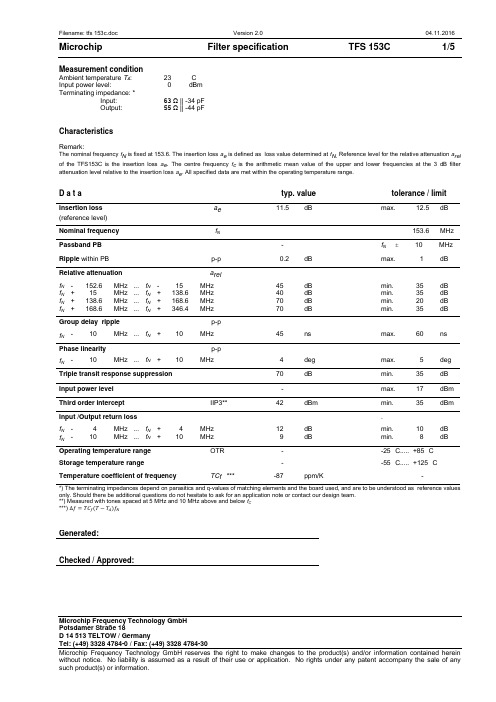
Measurement conditionAmbient temperature T A: 23 °CInput power level: 0 dBmTerminating impedance: *Input: 63 Ω || -34 pFOutput: 55 Ω || -44 pFCharacteristicsRemark:The nominal frequency f N is fixed at 153.6. The insertion loss a e is defined as loss value determined at f N. Reference level for the relative attenuation a rel of the TFS153C is the insertion loss a e. The centre frequency f c is the arithmetic mean value of the upper and lower frequencies at the 3 dB filter attenuation level relative to the insertion loss a e. All specified data are met within the operating temperature range.D a t a typ. value tolerance / limitInsertion loss a e11.5 dB max. 12.5 dB (reference level)Nominal frequency f N 153.6 MHz Passband PB - f N 10 MHz Ripple within PB p-p 0.2 dB max. 1 dB Relative attenuation a relf N- 152.6 MHz ... f N- 15 MHz 45 dB min. 35 dBf N+ 15 MHz ... f N+ 138.6 MHz 40 dB min. 35 dBf N+ 138.6 MHz ... f N+ 168.6 MHz 70 dB min. 20 dBf N+ 168.6 MHz ... f N+ 346.4 MHz 70 dB min. 35 dB Group delay ripple p-pf N- 10 MHz ... f N+ 10 MHz 45 ns max. 60 ns Phase linearity p-pf N- 10 MHz ... f N+ 10 MHz 4 deg max. 5 deg Triple transit response suppression 70 dB min. 35 dB Input power level - max. 17 dBm Third order intercept IIP3** 42 dBm min. 35 dBm Input /Output return loss .f N- 4 MHz ... f N+ 4 MHz 12 dB min. 10 dBf N- 10 MHz ... f N+ 10 MHz 9 dB min. 8 dB Operating temperature range OTR - -25 °C..... +85 °C Storage temperature range - -55 °C..... +125 °C Temperature coefficient of frequency TC f *** -87 ppm/K -*) The terminating impedances depend on parasitics and q-values of matching elements and the board used, and are to be understood as reference values only. Should there be additional questions do not hesitate to ask for an application note or contact our design team.**) Measured with tones spaced at 5 MHz and 10 MHz above and below f C***) ∆f=TC f(T−T A)f NGenerated:Checked / Approved:Microchip Frequency Technology GmbHPotsdamer Straße 18Microchip Frequency Technology GmbH Potsdamer Straße 18 Filter characteristicConstruction and pin connection(All dimensions in mm)50 Ω Test circuitL2Output 50 OhmInput L11,2,3,4,6,7,8,9,10,121 Ground2 Ground3 Ground4 Ground5 Output6 Ground7 Ground8 Ground9 Ground 10 Ground 11 Input 12 GroundDate code: Year + week H 2016 J 2017 K 2018 ...Microchip Frequency Technology GmbH Potsdamer Straße 18 Stability characteristics, reliabilityAfter the following tests the filter shall meet the whole specification:1. Shock: 500 g, 1 ms, half sine wave, 3 shocks each plane; DIN IEC 60068 T2 - 272. Vibration: 10 Hz to 2000 Hz, 0.35 mm or 5 g respectively, 1 octave per min, 10 cycles perplane, 3 planes; DIN IEC 60068 T2 - 63. Change of temperature: -55 °C to 125 °C / 15 min. each / 100 cycles DIN IEC 60068 part 2 – 14 Test N4. Resistance tosolder heat (reflow): reflow possible: three times max.; for temperature conditions refer to the attached "Air reflow temperature conditions" on page 4;5. SAW devices are Electrostatic Discharge (ESD) sensitive devices.This filter is RoHS compliant (2011/65/EU)PackingTape & Reel: IEC 286 – 3, with exception of value for N and minimum bending radius; tape type II, embossed carrier tape with top cover tape on the upper side; max. pieces of filters per reel:1700reel of empty components at start:min. 300 mm reel of empty components at start including leader: min. 500 mm trailer:min. 300 mmGDoWC tFEGD1P 2P 1P o BoAoP ull Off DirectionP IN Marker T ypDate Code K o tThe minimum bending radius is 45 mm.Tape (all dimensions in mm) W : 24.00 +0.30/-0.10 Po : 4.00 ±0.1 Do : 1.50 +0.1/0 E : 1.75 ±0.10 F : 11.50 ±0.10 G(min) : 0.60 P2 : 2.00 ±0.1 P1 : 12.00 ±0.1 D1(min) : 1.50 Ao : 7.00 ±0.10 Bo : 13.80 ±0.10 Ct : 21.00 ±0.1 Ko: 2.10 ±0.10 t : 0.30 ±0.05Reel (all dimensions in mm) A : 330 or 180 W1 : 24.4 +2/-0 W2(max) : 30.40 N(min) : 60.00 C : 13.0 +0.5/-0.2Microchip Frequency Technology GmbH Potsdamer Straße 18 Air reflow temperature conditionsConditionsExposureAverage ramp-up rate (30 °C to 217 °C) less than 3 °C / second> 100 °C between 300 and 600 seconds > 150 °C between 240 and 500 seconds > 217 °Cbetween 30 and 150 seconds Peak temperaturemax. 260 °CTime within 5 °C of actual peak temperature between 10 and 30 seconds Cool-down rate (Peak to 50 °C)less than 6 °C / secondTime from 30 °C to Peak temperatureno greater than 300 secondsTemperature / °CTime / smax. 260 °C217 °C10 ... 30 s 30 ... 150 smax. 300 sChip-mount air reflow profileHistoryVersion Reason of Changes Name Date1.0 - generation of specification according to customer requirements Roizengaft 02.02.2004 1.1 - generated filter specification Chilla 15.06.2004- added termination impedances- added typical values- changed insertion loss- changed group delay ripple- changed phase linearity- changed input/output return loss- changed IP3 description- changed storage temperature range- deleted description for power level- added filter characteristic- changed construction and pin connection- added test circuit- changed packing1.2 - added temperature coefficient of frequency Chilla 23.09.2005 1.3 - added IIP3 Chilla 27.02.20091.4 - changed temperature coefficient Chilla 06.04.20092.0 - Change tape & reel dimensions Bonnen 04.11.2016- Update header and footer sections- Update data section- Update storage temperature range- Update stability characteristics, reliabilityMicrochip Frequency Technology GmbHPotsdamer Straße 18。
PMC-651F馈线保护测控装置用户说明书_V5.2
我们已经检查了本手册关于描述硬件和软件保持一致的内容。由于不可能完全消除差错,所以我们不 能保证完全的一致。本手册中的数据将定期审核,并在新一版的文件中做必要的修改,欢迎提出修改建议。 以后版本中的变动不再另行通知。
3 功能说明...................................................................................................................................................................6 3.1 保护功能.......................................................................................................................................................7 3.1.1 辅助元件.......................................................................................................................................... 7 3.1.2 大电流闭锁保护............................................................................................................................ 10 3.1.3 相电流充电保护............................................................................................................................ 10 3.1.4 相电流加速保护............................................................................................................................ 11 3.1.5 开入加速相电流保护.................................................................................................................... 11 3.1.6 瞬时电流速断保护........................................................................................................................ 12 3.1.7 限时电流速断保护........................................................................................................................ 13 3.1.8 复压(方向)过流保护................................................................................................................ 14 3.1.9 过负荷保护.................................................................................................................................... 15 3.1.10 反时限过流保护.......................................................................................................................... 16 3.1.11 IN 充电保护................................................................................................................................. 17 3.1.12 IN 加速保护................................................................................................................................. 17 3.1.13 IN 过流保护................................................................................................................................. 18 3.1.14 IN 反时限过流保护..................................................................................................................... 19 3.1.15 I0 充电保护................................................................................................................................. 19 3.1.16 I0 加速保护................................................................................................................................. 20 3.1.17 I0 过流保护................................................................................................................................. 20 3.1.18 I0 反时限过流保护..................................................................................................................... 21 3.1.19 过电压保护.................................................................................................................................. 21 3.1.20 低电压保护.................................................................................................................................. 22 3.1.21 低压解列保护.............................................................................................................................. 23
德特威勒 产品手册
09cablingsystem13 产品清单目录光纤系统13unilanR 光纤系统简介 14unilanR 单模零水峰光纤特性 18unilanR 多模光纤特性 19unilanR 万兆光纤特性 20unilanR OF01系列室内光缆 21unilanR OF03系列室外光缆 22unilanR OF04系列室外光缆 23unilanR OF05系列室内光缆 24unilanR OF06系列室外光缆 25optofilR-ZGGFR-Safety / U-DQ(ZN)BH 可用于室内和室外的安全光缆 26 unilanR-wbGGFR-Safety / U-DQ(ZN)BH 可用于室内和室外的安全光缆 27 unilanR 室内外通用光缆 28unilanR 室外光缆 29unilanR 光纤连接产品系列 30OP07 光纤安装系列 35屏蔽系统36unilanR 屏蔽系统简介 37unilanR 超五类屏蔽线缆 40unilanR 超五类/六类屏蔽模块 42unilanR 超五类/六类屏蔽配线架 43unilanR 六类屏蔽线缆 44unilanR MS六类屏蔽模块 46unilanR MPS六类屏蔽配线架框架 47unilanR MS六类屏蔽配线架框架 47unilanR 六A类屏蔽线缆 48unilanR 六A类屏蔽模块 49unilanR 六A类屏蔽配线架 50unilanR 七类屏蔽线缆 51unilanR 七A类屏蔽线缆 54unilanR GG-45系列7类模块 55Unipatch PS 系列7A类模块 56unilanR 屏蔽跳线和管理环 57unilanR 面板 58unilanR 工具 60非屏蔽系统61unilanR 非屏蔽系统简介 62unilanR 超五类/六类非屏蔽模块 63unilanR 超五类/六类非屏蔽配线架 64unilanR 六类非屏蔽线缆 65unilanR 六类非屏蔽跳线 66unilanR 超五类非屏蔽线缆 67unilanR 超五类非屏蔽跳线 68e-lineR 非屏蔽超五类系列 69e-lineR 非屏蔽模块 70e-lineR 非屏蔽配线架 71e-lineR 非屏蔽线缆 72unilanR 110系列 73unilanR CU25/50三类语音配线架 74uninetR 三类语音大对数电缆线对 75uninetR 三类UTP 25对/50对/100对类室内大对数电缆 76 uninetR 三类UTP 25对/50对/100对类室外大对数电缆 77 unilanR 面板 78表面安装盒 80unilanR 管理环 81弹起式三口地面插座盒 81unilanR 系统附件 82德特威勒光纤系统解决方案unilan® 单模零水峰光纤特性德特威勒单模零水峰光纤特性;符合ITU-T Rec. G652D ;GB/T 9771.3-2000满足IEEE802.3ae 标准,支持10GBASE-L 万兆以太网达1000米以上距离及1000Base-LX 千兆以太网达5000米以上距离,向下兼容目前的100Mbps 及10Mbps 以太网应用Unilan®多模光纤特性符合IEC 60793-2-10、YD/T 1258.4-2005、GB 50311-2007、ISO/IEC 11802-2002、EN50173.1-2007、TIA-568C.3-2009标准,适用于中等传输距离的局域网,基于850nm和1300nm波长的中等传输速率。
测速雷达主要设备功能及技术参数

测速雷达主要设备功能及技术参数测速雷达型号:KTR-C3(品牌:KITOZER/开拓者)采用高速DSP信号处理芯片、0.1秒快速捕捉。
1)设计小巧轻便、制作精良。
2)纯铸铁结构,坚固耐用。
3)232串口输出。
4)精确度高,捕捉目标速度快。
5)动态时具有同向功能。
6)静态时可分别检测来车、去车。
7)静态测速范围:0~322 KPH。
8)移动测速范围:19~322KPH。
9)环境要求:温度:-30度 ~ +70度;湿度:0 % ~ 90% 。
10)Ka波段窄波雷达,微波频率:34.7GHz(Ka-band),可有效规避探测狗检测。
11)发射角:±4度。
12)规格:重:0.52kg、直径:6.7cm、长:11.8cm。
13)精确度:+/-1KPH。
高清摄像机(品牌:KITOZER/开拓者)高清摄像机功能:CCD成像,200万象素,主要端口有:闪光灯同步口,通过同步线与闪光灯连接;拍照触发口,当收到外部脉冲触发信号时,高清摄像机会抓取一张图片,脉冲信号由独立的拍照触发器发出;网口(100M),与控制主机连接,接收参数配置,上传图片,也可接收带由协议内容的抓拍命令。
产品详细参数表百万像素变焦镜头日本精工本次中煤平朔公司系统百万像素变焦镜头选型为日本精工SE5018MP产品,AVENIR ETOKU(日本精工)十几年来始终专心于监控镜头的市场发展,成为中国安防监控领域用得最多的专业镜头。
本次系统高清摄像机选型为广州莱安智能化系统开发有限公司出品的KTR200A型高清摄像机。
KTR200A是集成一体的高速彩色/单色智能工业相机,采用总像素200万像素的CCD图像传感器,具有处理速度快、分辨率高、图像质量好等特点。
广泛应用于智能交通、电子警察、卡口、高速公路、停车厂等领域的检测和识别。
百万像素网络拍照摄像一体机,将高清图像抓拍、标清视频摄像完美结合,超高清晰度,分辨率达130万~500万像素,专业用于如平安城市建设、机场、银行、道路卡口监控及牌照识别等安全防范领域,能够为客户提供专业的可定制产品及服务,支持后续增值开发。
电源开关管参数文档
电源开关管参数时间:2009-02-09 05:39:19 来源:本站原创作者:天才白痴浏览:1512BU2525AX 30 NPN 开关功放1500V 12A 150W 350NSBU2527AF 30 NPN 开关功放1500V 15A 150WD1555 BCE NPN 彩行1500V 5A 80WD1556 BCE NPN 彩行1500V 6A 80WD1559 BCE NPN 达林顿功放100V 20A 100W B1079D1590 28 NPN 达林顿功放150V 8A 25WD1623 28B NPN 彩行1500V 4A 70WD1849 50A NPN 彩行1500V 7A 120WD1850 50A NPN 彩行1500V 7A 120WD1975 53A NPN 音频功放180V 15A 150W B1317BU2532AW 30 NPN 开关功放1500V 15A 150WBU2520AF 30 NPN 开关功放1500V 10A 150W 1/500NSBU2520DF 30 NPN 开关功放1500V 10A 150W 1/500NSBU2520DX 30 NPN 开关功放1500V 10A 50W 600NSBUH515 BCE NPN 行管1500V 10A 80WBUH515D BCE NPN 行管1500V 10A 80WBUS13A 12 NPN 开关功放1000V 15A 175WD2155 53A NPN 音频功放180V 15A 150WD2256 46 NPN 达林顿功放120V 25A 125W B1494D2334 28B NPN 彩行1500V 5A 80WD2335 BCE NPN 彩行1500V 7A 100W 带阻尼D2349 BCE NPN 大屏彩显行管1500V ±10A 50WD1959 BCE NPN 彩行1400V 10A 50W60MIAL1 微波炉1000V 60A 300WT30G40 BCE NPN 大功率开关管400V 30A 300WC4059 BCE NPN 高速开关600V 15V 130W 0.5/2.2USC4106 BCE NPN 电源开关500V 7A 50W 20MHZ?C4111 BCE NPN 开关行管1500V 10A 150WC3679 BCE NPN 电源开关900V 5A 100W 6MHZC2898 28 NPN 音频功放开关500V 8A 50WC2922 43 NPN 音频功放开关180V 17A 200W 50MHZ A1216C3026 12 NPN 开关管1700V 5A 50WC3262 BCE NPN 功放800V 10A 100WC3264 BCE NPN PA功放开关230V 17A 200WB=170 A1295C3280 30 NPN 音频功放开关160V 12A 120WB=100C3281 30 NPN 音频功放开关200V 15A 150W 30MHZC3680 BCE NPN 电源开关900V 7A 120W 6MHZC3688 BCE NPN 彩行1500V 10A 150WC3720 12 NPN 彩行1200V 10A 200WC3995 BCE NPN 行管1500V 12A 180WD1025 28 NPN 达林顿功放200V 8A 50WC3997 BCE NPN 行管1500V 15A 250WC3998 BCE NPN 行管1500V 25A 250WC4024 BCE NPN 功放开关100V 10A 35W 24MHZD1037 BCE NPN 音频功放开关150V 30A 180WD1047 30 NPN 音频功放开关160V 12A 100W B817C4119 BCE NPN 微波炉开关1500V 15A 250WC4237 BCE NPN 高压高速开关1000V 8A 120W 30MHZ C4242 BCE NPN 高压高速开关450V 7A 40WC4297 BCE NPN 电源开关500V 12A 75W 10MHZC4429 BCE NPN 电源开关1100V 8A 60WC4532 BCE NPN 大屏行管1700V 10A 200WC4582 BCE NPN 电源开关600V 15A 75W 20MHZC5244 BCE NPN 彩行1700V 15A 200WC5250 BCE NPN 开关1000V 7A 100WC5251 BCE NPN 彩行1500V 12A 50WD1071 28 NPN 达林顿功放300V 6A 40WC4706 BCE NPN 电源开关900V 14A 130W 6MHZC4742 46 NPN 彩行1500V 6A 50WC4745 46 NPN 彩行1500V 6A 50WC4747 46 NPN 彩行1500V 10A 50WC4769 BCE NPN 微机行管1500V 7A 60WC4927 BCE NPN 行管1500V 8A 50WC4927 BCE NPN SONY29行管1500V 8A 50WC4941 BCE NPN 行管1500V 6A 65W 500/380NSC5020 BCE NPN 彩行1000V 7A 100WC5068 BCE NPN 彩行1500V 10A 50WC5086 BCE NPN 彩行1500V 10A 50WC5088 BCE NPN 彩行1500V 10A 50WC5129 BCE NPN 彩显行管1500V 8A 50WD1163A 28 NPN 行偏转用350V 7A 40W 60MHZD1175 12 NPN 行偏转用1500V 5A 100WC5132 BCE NPN 彩行1500V 16A 50WC5144 BCE NPN 大屏彩行1700V 20A 200WC5148 BCE NPN 大屏彩行1500V 8A 50WC5149 BCE NPN 高速高频行管1500V 8A 50WC5198 BCE NPN 功放开关140V 10A 100WC5200 BCE NPN 功放开关230V 15A 150W A1943C5207 BCE NPN 彩行1500V 10A 50WC5243 BCE NPN 彩行1700V 15A 200WC5252 BCE NPN 彩行1500V 15A 100WC5294 BCE NPN 彩行1500V 20A t=200MSC5296 BCE NPN 开关管带阻1500V 8A 80WC5297 BCE NPN 开关管1500V 16A 60WC5331 BCE NPN 大屏彩显行管1500V 15A 180W D325 BCE NPN 功放开关50V 3A 25WD385 11 NPN 达林顿功放100V 7A 30WD1398 BCE NPN 开关1500V 5A 50W 3MHZD1403 BCE NPN 彩行1500V 6A 120W。
Lenovo W20无线传输器说明书

Statement
Welcome to use Lenovo W20 Wireless Transmitter Before installing and using this product for the first time, please read all the materials attached with the product carefully for better use of the product. Failure to operate according to the instructions, unauthorized maintenance, inflow of water in the product, product falling or other accidents will lead to data loss, malfunction of system restore or other losses. Please keep the product and instruction manual properly, operate in strict accordance with the instructions, and back up the data in time before operating according to the instructions. If you fail to operate according to the instruction manual, or operate in a wrong way due to misunderstanding, you will suffer data loss or other losses. Please keep the product and instruction manual properly, and operate in strict accordance with the instruction manual, and back up the data in time before operating according to the instruction manual. Lenovo (Beijing) Co., Ltd. has proofread this instruction manual carefully. But we can't guarantee that this instruction manual is completely free of any mistakes and omissions. This instruction manual and pictures used in it are for reference only. If there is any discrepancy between some pictures and the actual display of the product, the actual display shall prevail. To provide better services, Lenovo (Beijing) Co., Ltd. reserves the right to improve and/or modify the products and software programs described in this instruction manual and the contents of this instruction manual at any time without prior notice. Lenovo (Beijing) Co., Ltd. The contents of this instruction manual are protected by laws and regulations. Without the prior written authorization of Lenovo (Beijing) Co., Ltd., you are not allowed to copy or transcribe this instruction manual in any way, transmit this instruction manual in any form over any wired or wireless network, or translate this instruction manual into any language.
光端机安装使用手册

光端机说明书数字式视.音频及控制数据光端机目录1、概要 (2)2、一般安全要求 (2)3、应用场合 (2)4、数字光端机产品分类及产品说明 (3)5、数字光端机技术参数 (11)6、产品技术特点 (12)7、系统连接图 (13)8、安装步骤 (13)9、控制数据、音频信号端口及接口线定义 (15)10、简单故障检查分析与排除2111、 ..................................................................................................................... 附件22一、概要非常感谢您选用我公司生产的高可靠数字视音频及控制数据光传输系统!持续为用户提供优质产品和优质服务是我们的目标。
为确保您正确、安全地使用我们的产品,敬请您在使用前仔细阅读本手册,以减少或避免在安装和使用过程中可能遇到的问题。
视音频光端机因视频路数、音频路数、控制数据路数及其信号传输方向的不同,使光端机的型号繁多。
本手册中将同一基本配置衍生的系列产品归为一个产品组,同一产品组产品的使用及连接方法类同。
对每一产品组就其主要代表性型号的配置及使用连接方法都进行了详细说明。
实际购买的产品在型号、配置上不一定会与说明书列出的严格一致,但都在说明书的范围以内。
请根据产品的基本配置,查找归类的产品组,再进一步详细了解使用及连接方法。
本手册为3500、4500 两大系列产品线所有型号数字视音频及控制数据光端机的通用说明书。
请阅读下列安全注意事项,以避免人身伤害,并防止本产品或与其相连的任何其他产品受到损坏。
为了避免可能发生的危险,本产品只可在规定范围内使用。
只有我公司授权的技术人员方可执行维修。
□使用适当的电源。
仔细核对产品的电源类型以及正负极性。
□正确的连接和断开。
当设备正处于上电状态时,请勿随意连接和断开数据线。
□正确的信号线连接。
Alcatel 1531中文说明书
Alcatel 1531中文说明书北京天诺泰利通信技术有限公司2001年8月目录一、概述 (3)二、设备特点 (4)三、系统应用 (4)四、系统描述 (5)五、功能描述 (7)5.1 透明的传输模式(Transparent Transmission Mode) (7)5.2 ISDN PRA传输模式 (8)5.3 专线模式(SLL) (8)5.4 X.21数据传输模式 (9)六、设备维护描述 (10)6.1 64Kbit/s数据通路 (10)6.2 Q2远端总线访问 (10)6.3 内部集成的管理平台 (11)6.4 在没有CNCC模块下的管理 (11)6.5 在CNCC模块下的管理 (11)6.6 工程电话接口 (11)6.7 设置 (11)6.8 系统保护 (11)七.设备的物理特性 (12)7.1 Alcatel 1531FL S9机框物理描述 (12)7.2 Alcatel 1531FL 3U的物理描述 (12)7.3 Alcatel 1531FL 3U设备的220V电源模块1531 PL PU (14)7.4 手持终端HHT的物理描述 (14)八、设备安装 (15)8.1 Alcatel 1531FL S9机框的安装 (15)8.2 Alcatel 1531FL 3U的安装 (15)8.3 Alcatel 1531FL系统运行 (15)九、系统技术数据 (16)9.1 光模块组件 (16)9.2 光功率 (16)9.3 2 Mbit/s接口 (16)9.4辅助数据通道 (16)9.5 光接口 (17)9.6 告警接口 (17)9.7 电源指标 (17)9.8 机械规格 (17)9.9 环境规范 (17)9.10 MTBF (18)一、概述在未来的宽带BISDN 的发展中,高带宽,大数据容量对光传输越来越成为主流的发展方向,在支持当前的宽带业务中,发展N ×2M 的光纤线路将具有最佳的投资效益.Alcatel 1531FL ,16×2M 的光接入网系统的设计和功能最适合用户的光接入网的光端产品, 它也是最佳的用于短距离,中距离,长距离的光传输产品.图1:16×2M 光接入示意图Alcatel 1531 FL 可用于单模和多模光纤,可在一对光纤上双向对称的传输光信号,也可以在单根光纤上双向传输光信号。
诺瓦科技LED显示屏联网播放器T3规格书英文版

Taurus SeriesMultimedia PlayersT3 SpecificationsProduct Version: V1.3.0 Document Number:NS120100242XI 'AN NOVA ST A R TEC H C O .,L T D .Copyright © 2018 Xi’an NovaStar Tech Co., Ltd. All Rights Reserved.No part of this document may be copied, reproduced, extracted or transmitted in any form or by any means without the prior written consent of Xi’an Nova Star Tech Co., Ltd.Trademarkis a trademark of Xi’an NovaStar Tech Co., Ltd.StatementYou are welcome to use the product of Xi’an NovaStar Tech Co., Ltd. (hereinafter referred to as NovaStar). This document is intended to help you understand and use the product. For accuracy and reliability, NovaStar may make improvements and/or changes to this document at any time and without notice. If you experience any problems in use or have any suggestions, please contact us via contact info given in document. We will do our best to solve any issues, as well as evaluate and implement any suggestions.X I'A NN OV AS TA RT EC HC O.,L TD.Table of ContentsTable of Contents ............................................................................................................................ ii 1 Safety .. (1)1.1 Storage and Transport Safety ..................................................................................................................... 1 1.2 Installation and Use Safety .. (1)2 Overview (3)2.1 Introduction .................................................................................................................................................. 3 2.2 Application ................................................................................................................................................... 3 3 Features ........................................................................................................................................... 5 3.1 Synchronization mechanism for multi-screen playing ................................................................................. 5 3.2 Powerful Processing Capability ................................................................................................................... 5 3.3 Omnidirectional Control Plan .. (5)3.4 Dual-Wi-Fi Mode .......................................................................................................................................... 6 3.4.1 Wi-Fi AP Mode .......................................................................................................................................... 7 3.4.2 Wi-Fi Sta Mode .. (7)3.4.3 Wi-Fi AP+Sta Mode .................................................................................................................................. 7 3.5 Redundant Backup ...................................................................................................................................... 8 4 Hardware Structure....................................................................................................................... 9 4.1 Appearance . (9)4.2 Dimensions (11)5 Software Structure (12)5.1 System Software ........................................................................................................................................ 12 5.2 Related Configuration Software .. (12)6 Product Specifications ................................................................................................................ 13 7 Audio and Video Decoder Specifications (15)7.1 Image ......................................................................................................................................................... 15 7.1.1 Decoder .................................................................................................................................................. 15 7.1.2 Encoder .................................................................................................................................................. 15 7.2 Audio .......................................................................................................................................................... 16 7.2.1 Decoder .. (16)X I 'A N N O V A S T A R T E C H C O .,L T D.7.2.2 Encoder (16)7.3 Video (17)7.3.1 Decoder (17)7.3.2 Encoder (18)X I'A NN OV AS TA RT EC HC O.,L TD.1SafetyThis chapter illustrates Taurus series products safety to ensure storage, transportation, installation and usage safety of the products.Safety description is applicable to all personnel that contact or use the products. First, pay attention to following points:● Read throughout the description. ● Save the whole description.●Be complied with the whole description.1.1 Storage and Transport Safety ● Pay attention to dust and water prevention.● Avoid long-term direct sunlight. ● Do not place the products in the position near fire and heat.● Do not place the products in an area containing explosive materials. ● Do not place the products in strong electromagnetic environment. ● Place the products in a stable position to prevent damage or personal injury caused by dropping.●Save the packing box and materials which will come in handy if you ever have to ship your products. For maximum protection, repack your product as it wasoriginally packed at the factory.1.2 Installation and Use Safety● Only trained professionals may install the products.● Do not insert and unplug (power cord plug) when the power is on. ● Ensure the safe grounding of the device.● Be careful about electric shock risk. Built-in power supply. ● Always wear a wrist band and insulating gloves.● Do not place the products in an area having more or strong shake. ● Perform dust removing regularly.●Rather than having the product disassembled and maintained by non-certified professionals, please contact NovaStar for maintenance at any time.X I 'A N N O V A S T A R T E CHCO .,L T D.Replace faulty parts only with the spare parts supplied by NovaStar.X I'A NN OV AS TA RT EC HC O.,L TD.2Overview2.1 IntroductionTaurus series products are NovaStar's second generation of multimedia players dedicated to small and medium-sized full-color LED displays.T3 of the Taurus series products (herein after referred to as “T 3”) feature following advantages, better satisfying users’ requir ements:●Loading capacity up to 650,000 pixels●Synchronization mechanism for multi-screen playing● Powerful processing capability ● Omnidirectional control plan ● Dual-Wi-Fi mode ●Redundant backup Note: If the user has a high demand on synchronization, the time synchronization module isrecommended. For details, please consult our technical staff. In addition to solution publishing and screen control via PC, mobile phones and LAN, the omnidirectional control plan also supports remote centralized publishing and monitoring. 2.2 ApplicationTaurus series products can be widely used in LED commercial display field, such asbar screen, chain store screen, advertising machine, mirror screen, retail store screen, door head screen, on board screen and the screen requiring no PC. Classification of Taurus’ application cases is shown in Table 2-1. Table 2-1 ApplicationXI 'A N N O V A S T A R T E C H C O .,L T D.X I'A NN OV AS TA RT EC HC O.,L T3Features3.1 Synchronization mechanism for multi-screen playingThe T3 support switching on/off function of synchronous display.When synchronous display is enabled, the same content can be played on different displays synchronously if the time of different T3 units are synchronous with one another and the same solution is being played.3.2 Powerful Processing CapabilityThe T3 feature powerful hardware processing capability: ● 1.5 GHz eight-core processor●Support for H.265 4K high-definition video hardware decoding playback ● Support for 1080P video hardware decoding ● 2 GB operating memory●8 GB on-board internal storage space with 4 GB available for users 3.3 Omnidirectional Control Plan Table 3-1 Control PlanXI 'A N N O V A S T A R T E C H CO .,L T D.Cluster control plan is a new internet control plan featuring following advantages:●More efficient: Use the cloud service mode to process services through a uniformplatform. For example, VNNOX is used to edit and publish solutions, and NovaiCare is used to centrally monitor display status.● More reliable: Ensure the reliability based on active and standby disaster recovery mechanism and data backup mechanism of the server. ● More safe: Ensure the system safety through channel encryption, data fingerprintand permission management. ● Easier to use: VNNOX and NovaiCare can be accessed through Web. As long asthere is internet, operation can be performed anytime and anywhere. ●More effective: This mode is more suitable for the commercial mode of advertising industry and digital signage industry, and makes information spreading more effective. 3.4 Dual-Wi-Fi Mode The T3 have permanent Wi-Fi AP and support the Wi-Fi Sta mode, carryingadvantages as shown below:●Completely cover Wi-Fi connection scene. The T3 can be connected to through self-carried Wi-Fi AP or the external router.●Completely cover client terminals. Mobile phone, Pad and PC can be used to log in T3 through wireless network.●Require no wiring. Display management can be managed at any time, having improvements in efficiency.T3’s Wi -Fi AP signal strength is related to the transmit distance and environment. Users can change the Wi-Fi antenna as required.XI 'A NN O V A S T A R T E C H C O .,L T D3.4.1 Wi-Fi AP ModeUsers connect the Wi-Fi AP of a T3 to directly access the T3. The SSID is “AP + the last 8 digits of the SN ”, for example, “AP10000033”, and the default password is “12345678”.3.4.2 Wi-Fi Sta Mode Configure an external router for a T3 and users can access the T3 by connecting the external router. If an external router is configured for multiple T3 units, a LAN can becreated. Users can access any of the T3 via the LAN.3.4.3 Wi-Fi AP+Sta ModeIn Wi-Fi AP+ Sta connection mode, users can either directly access the T3 or accessinternet through bridging connection. Upon the cluster solution, VNNOX andNovaiCare can realize remote solution publishing and remote monitoring respectively through the Internet.XI 'A N N O V A S T A R T E C HCO .,L T D.3.5 Redundant BackupT3 support network redundant backup and Ethernet port redundant backup.●Network redundant backup: The T3 automatically selects internet connectionmode among wired network or Wi-Fi Sta network according to the priority.●Ethernet port redundant backup: The T3 enhances connection reliability throughactive and standby redundant mechanism for the Ethernet port used to connectwith the receiving card.X I'A NN OV AS TA RT EC HC O.,L TD.4Hardware Structure4.1 AppearanceFigure 4-1 Appearance of T3Note: Product images provided in this file are for reference only, and the actualproducts shall prevail.Table 4-1 Connectors and buttons of the T3XI 'AN NOVA S TAR T E C HCO .,L T D.Note: Product images provided in this file are for reference only, and the actual products shall prevail.Table 4-2 Indicators of the T3 A R T E C HCO .,L T D.4.2 DimensionsThe total thickness (board thickness + thickness of the components on the front andback side) is no greater than 25.0mm.Unit of the dimension chart is “mm”. Ground connection is enabled for location hole(GND).X I'A NN OV AS TA RT EC HC O.,L TD.5Software Structure5.1 System Software● Android operating system software ● Android terminal application software ●FPGA programNote: The third-party applications are not supported.5.2 Related Configuration SoftwareTable 5-1 Related configuration softwareE C HCO .,L T D.6 Product Specifications SpecificationsAntennaAntenna extension mastX I'A NN OV AS TA RT EC HC O.,L TD.7Audio and Video DecoderSpecifications7.1 Image7.1.1 Decoder7.1.2 EncoderO .,L T D.7.2 Audio 7.2.1 Decoder7.2.2 Encoder7.3 Video 7.3.1 DecoderNote: Output data format is YUV420 semi-planar, and YUV400(monochrome) is also supported for H.264.7.3.2 EncoderXI 'AN NOVA S。
施耐德电气微网MNL-10Rxx 15Rxx 20Rxx控制器技术手册说明书
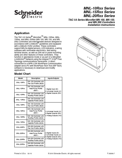
ApplicationThe TAC I/A Series MicroNet™ MNL-10Rxx, MNL-15Rxx, and MNL-20Rxx (MN 100, MN 150, and MN 200) Controllers are interoperable devices designed in accordance with L ON M ARK® guidelines and equipped with L ON M ARK HVAC profiles. These controllers support MN-Sx digital sensors. LED indicators, a wiring subbase with removable electronics, field wiring terminal blocks, as well as DIN rail or panel mounting ability are other features of these controllers. They function in standalone mode or as part of a MicroNet L ON W ORKS® Network using the integral FT 3150® Free Topology communications transceiver. A direct connection to a WPA-LON WorkPlace Communication adapter and a PC with WorkPlace Tech Tool (WP Tech) software is necessary to download and modify applications.Model ChartModel Description Inputs/OutputsMNL-10RFx MN 100 Controller withFan Coil Profile (8020)1 Digital Input (DI)2 Universal Inputs (UI)4 Digital Outputs (DO)MNL-10RHx MN 100 Controller with Heat Pump Profile(8051)MNL-10RRx MN 100 Controller with Rooftop Profile (8030)MNL -10RSx MN 100 Controller with Satellite Profile (8030)MNL-15RFx MN 150 Controller withFan Coil Profile (8020)3 Universal Inputs (UI)2 Digital Outputs (DO)2 Analog Outputs (AO)MNL-15RHx IMN 150 Controller with Heat Pump Profile(8051)MNL-15RRx MN 150 Controller with Rooftop Profile (8030)MNL-15RSx MN 150 Controller with Satellite Profile (8030)MNL-20RFx MN 200 Controller withFan Coil Profile (8020)2 Digital Inputs (DI)3 Universal Inputs (UI)6 Digital Outputs (DO)2 Analog Outputs (AO)MNL-20RHx MN 200 Controller with Heat Pump Profile(8051)MNL-20RRx MN 200 Controller with Rooftop Profile (8030)MNL-20RSx MN 200 Controller withSatellite Profile (8030)MNL-10Rxx SeriesMNL-15Rxx SeriesMNL-20Rxx SeriesTAC I/A Series MicroNet MN 100, MN 150,and MN 200 ControllersInstallation InstructionsPrinted in U.S.A.02-10© 2010 Schneider Electric. All rights reserved.F-26266-7Applicable DocumentationInstallationInspection Inspect carton for damage. If damaged, notify carrier immediately. Inspect controllers fordamage upon receipt.Requirements (These items not provided)•Installer must be a qualified, experienced technician.•Job wiring diagrams•T ools:–Drill and bits for panel mounting screws–Digital Volt-ohm meter (DVM)–Static protection wrist strap•MNA-FLO-1 enclosure for connecting to conduit (optional)•Class 2 power transformer supplying a nominal 24 Vac (20.4 to 30 Vac) with a minimum rating of 15 Va, 50/60 Hz per controller plus Digital Output (DO) loads (if sametransformer is used). In European Community, transformer must conform to EN 60742•T erminators:–One LON-TERM1 terminator required for each free topology segment–T wo LON-TERM2 terminators required for each bus topology segment•T wo #6 pan head panel mounting screws or 35mm DIN rail for mountingF-Number Description Audience PurposeF-26277T AC I/A Series MicroNetMN-Sx Series SensorsGeneral Instructions–Application Engineers–Installers–Service Personnel–Start-up TechniciansProvides step-by-step installation and checkout procedures for TACI/A Series MicroNet MN-Sx Series Sensors. Also containsinstructions for sensor operation.F-26303T AC I/A Series MicroNetSystem Overview–Application engineers–Installers–Start-up technicians–Service personnelProvides an overview of the T AC I/A Series MicroNet System. Itincludes brief descriptions of the hardware and software components,and how they may be combined to create MicroNet networks andstand-alone systems.F-27254WorkPlace Tech Tool 4.0Engineering Guide–Application Engineers–Installers–Service Personnel–Start-up TechniciansProvides engineering and technical information for applying andusing all aspects of WorkPlace T ech T ool.F-26507T AC I/A Series MicroNetSystems EngineeringGuide–Application Engineers–Installers–Service Personnel–Start-up TechniciansProvides engineering and technical information to assist indesigning a complete MicroNet controller system using differentarchitectures, components, and software.F-27255WorkPlace Tech Tool 4.0User’s Guide–Application Engineers–Installers–Service Personnel–Start-up TechniciansProvides step-by-step instructions for using WorkPlace Tech T ool.F-26363EN-206 Guidelines forPowering Multiple Full-Wave and Half-WaveRectifier Devices from aCommon Transformer–Application Engineers–Installers–Service PersonnelOffers guidelines for avoiding equipment damage associated withimproperly wiring devices of varying rectifier types. Containsinstructions for identifying device rectifier type, guidelines forcorrectly powering devices of varying rectifier types, and examplesillustrating proper power wiring techniques.2© 2010 Schneider Electric. All rights reserved.F-26266-7Precautions GeneralWarning:Electrical shock hazard! Disconnect power before installing or removing thecover.•Follow Static precautions when installing this equipment.•Use copper conductors that are suitable for 167°F (75°C).•Make all connections according to electrical wiring diagram, national and local electricalcodes.Static PrecautionsStatic charges damage electronic components. The microprocessor and associated circuitryare extremely sensitive to static discharge. Use the following precautions when installing,servicing, or operating the system.•Work in a static-free area.•Discharge static electricity by touching a known, securely grounded object.•Use a wrist strap connected to earth ground when handling the controller’s printedcircuit board.Federal Communications Commission (FCC)This equipment has been tested and found to comply with the limits for a Class B digitaldevice, pursuant to Part 15 of the FCC Rules. These limits are designed to providereasonable protection against harmful interference in residential installations. Thisequipment generates, uses, and can radiate radio frequency energy and may cause harmfulinterference if not installed and used in accordance with the instructions. Even wheninstructions are followed, there is no guarantee that interference will not occur in a particularinstallation. If this equipment causes harmful interference to radio or television reception—which can be determined by turning the equipment off and on—the user is encouraged totry to correct the interference by one or more of the following measures:•Reorient or relocate the receiving antenna.•Increase the separation between the equipment and receiver.•Connect the equipment to an outlet on a circuit different from that to which the receiveris connected.•Consult the dealer or an experienced radio/television technician for help.Canadian Department of Communications (DOC)This class B digital apparatus meets all requirements of the Canadian Interference-CausingEquipment Regulations.European Community DirectivesThis equipment meets all requirements of European Community Directives for Low Voltage(72/23/EEC), General Safety (92/59/EEC), and Electromagnetic Compatibility(89/336/EEC).Location These controllers are suitable for indoor use only.Caution:•Avoid locations where excessive moisture, corrosive fumes, vibration, or explosivevapors are present.•Avoid electrical noise interference. Do not install near large contactors, electricalmachinery, or welding equipment.•Locate where ambient temperatures do not exceed 140°F (60 °C) or fall below -40°F(-40 °C) and relative humidity does not exceed 95% or fall below 5%, non-condensing. F-26266-7© 2010 Schneider Electric. All rights reserved..34© 2010 Schneider Electric. All rights reserved.F-26266-7F-26266-7© 2010 Schneider Electric. All rights reserved..56© 2010 Schneider Electric. All rights reserved.F-26266-7F-26266-7© 2010 Schneider Electric. All rights reserved..7Communications WiringCaution:•Communication wire pairs must be dedicated to MN-Sx (S-Link) and MicroNetL ON W ORKS network (LON) communications. They cannot be part of an active, bundledtelephone trunk.•Shielded cable is not required for S-Link or LON wiring.•If the cable is installed in areas of high RFI/EMI, the cable must be in conduit.•If shielded wire is used, the shield must be connected to earth ground at one end onlyby a 470K ohm 1/4 watt resistor. Shield must be continuous from one end of the trunkto the other.Communications wiring includes a connection between the controller and a TAC I/A SeriesMicroNet Sensor via the S-Link and a connection between the controller and the MicroNetL ON W ORKS Network (LON). An optional L ON W ORKS Network connection between thecontroller and one TAC I/A Series MicroNet Sensor is also possible.Sensor Link (S-Link) WiringS-Link wiring powers and enables the MN-Sx sensor. The S-Link needs at least 24 gage(0.51mm), twisted pair, voice grade telephone wire. The capacitance between conductorscannot be more than 32 pF per foot (0.3m). If shielded cable is used, the capacitancebetween any one conductor and the others, connected to the shield, cannot be more than60 pF per foot (0.3m). Maximum wire length is 200 ft. (61m).Note:•Controller supports one TAC I/A Series MicroNet Sensor (MN-Sx).•S-Link wiring is polarity insensitive.•If conduit is used between a T AC I/A Series Sensor and a controller, the MicroNetL ON W ORKS network and S-Link wiring can be in the same conduit, however, they mustbe separate cables.•S-Link wiring can be in the same conduit with UI, AO, and DI Wiring.MicroNet L ON W ORKS Network (LON) WiringAn approved Category 4 or 5, twisted-pair (two conductors) cable may be used for bothconnecting to the MicroNet L ON W ORKS Network and the optional L ON W ORKS Networkconnection between the controller and MN-Sx sensor. L ON W ORKS Network wiring is polarityinsensitive.Caution:Do not mix with UI, AO, DI or DO types of wiring. If conduit is used between aT AC I/A Series Sensor and a controller, L ON W ORKS Network wiring and S-Link wiring canbe in the same conduit, however, they must be separate cables.MN 100, MN 150, and MN 200 controllers use L ON W ORKS Free T opology Transceiver (FT3150) and support polarity insensitive bus (daisy-chain) and free (all combinations of star,tee, and loop) wiring topologies. A maximum of 62 nodes can be connected per segment.Note:See T AC I/A Series MicroNet System Engineering Guide, F-26507 to design aMicroNet L ON W ORKS TP/FT-10 network, including recommended topologies andapproved cable types.•Use of the LON terminals to connect to the MN-Sx sensor permits use of thesensor’s built-in LON Jack.•To preserve the integrity of the network, the LON wiring connecting a TAC I/A SeriesMicroNet controller to an MN-Sx sensor must be run to the sensor and back, indaisy-chain fashion. A wire “spur” must not be used to connect the sensor to thecontroller.•While the MN-Sx sensor is not counted as a “node” in the LonWorks network(LON), all LON wiring to the sensor must be counted when determining the lengthof the FTT wiring segment.8© 2010 Schneider Electric. All rights reserved.F-26266-7I/O WiringI/O connections include universal inputs, analog outputs, digital inputs, and digital outputs. See Figure-2, Figure-3, and Figure-4 for proper wire terminal information.Caution:If shielded cable is used, connect only one end of the shield to earth ground at controller.Universal Inputs (UI), Analog Outputs (AO), and Digital Inputs (DI)Caution:•Input and output devices cannot share common wiring. Each connected device requiresa separate signal and return conductor.•Power wiring cannot share conduit with UI, AO, S-Link, LON, or DI wiring.Note:•If maximum closed switch voltage is not more than 1.0 V and minimum open switch voltage is at least 4.5 V, then solid state switches may be used for a UI or a DI. •UI, AO, DI, and S-Link wiring can share a single conduit.UI, AO, DI, wiring needs at least 24 gage (0.51mm), twisted pair, voice grade telephone wire. The capacitance between conductors cannot be more than 32 pF per foot (0.3m). If shielded cable is used, the capacitance between any one conductor and the others, connected to the shield, cannot be more than 60 pF per foot (0.3m). T able-1 provides wiring specifications. Table-1UI, AO, and DI Wiring Specifications.ConnectionGageAWG (mm)Maximum Distanceft. (m)UI, AO, and DI 18 (1.02)300 (91) 20 (.81)200 (61) 22 (.65)125 (38) 24 (.51)75 (23)F-26266-7© 2010 Schneider Electric. All rights reserved..910© 2010 Schneider Electric. All rights reserved.F-26266-7F-26266-7© 2010 Schneider Electric. All rights reserved..1112© 2010 Schneider Electric. All rights reserved.F-26266-7F-26266-7© 2010 Schneider Electric. All rights reserved..1314© 2010 Schneider Electric. All rights reserved.F-26266-7Table-3LED Indication.Indicator Context Status Corrective ActionData Reception LED – amber Anytime Blinks when the controller receives data from theL ON W ORKS Network.None required.On indicates a possible network connection problem, or alarge amount of network traffic is present.Remove the L ON W ORKS Networkconnections from the controllerand determine if the LED goes off.If the LED does not go off, replacethe controller. If the LED does gooff, check the network topology(connections to each node, rout-ers, terminators, etc.) and theamount of traffic on the network. Off indicates that data reception is not taking place.None RequiredData Transmission LED – Green AnytimeBlinks when the controller transmits data to theL ON W ORKS Network.On indicates that the controller is not transmitting data.On also indicates that power is being applied to thecontroller.Off indicates no power to controller.Check powerService LED – Red Power-up The LED blinks once to indicate successful power-up.None RequiredWink modeBlinks (3 seconds on, 1 second off) three times to indicatephysical location of the controller. If a sensor (MN-Sx) isconnected, its red occupancy LED will flash (1/sec) duringthe wink period.AnytimeOn indicates that the neuron application is not running.Neuron applications are not field replaceable.Replace the controller.AnytimeBlinks (1/sec) to indicate that the neuron application isloaded, but the neuron’s communication parameters arenot loaded, are being reloaded, or have been corrupted.Neuron is considered unconfigured. Communicationparameters cannot be configured by field personnel.Use a third party network man-agement tool to commission thecontroller, or use the change statetool in WorkPlace T ech Tool (ver-sion 4.0 or greater) to set theNeuron® to the configured/on-linestate.While the controller is unconfig-ured, WP T ech can be used todownload an application, but atthe completion of the download,WP T ech versions 4.0 and higherwill restore the Neuron to theunconfigured state.AnytimeOff may indicate that the neuron application is loaded butthe device is off-line. In this state, a pre-loaded HVACapplication will not run.Use a third party network man-agement tool to commission thecontroller, or use the change statetool in WorkPlace T ech Tool (ver-sion 4.0 or greater) to set theNeuron to the configured/on-linestate.While the controller is off-line, WPTech can be used to download anapplication, but at the completionof the download, WP T echversions 4.0 and higher willrestore the Neuron to the off-linestate.AnytimeOff usually indicates a normal state. In this state, thecontroller operates normally, and you can downloadand/or run HVAC applications.If the controller is able to acceptand/or run a downloaded HVACapplication, no action is required.F-26266-7© 2010 Schneider Electric. All rights reserved..15Distributed, manufactured, and sold by Schneider Electric. I/A SERIES trademarks are owned by Invensys Systems, Inc. and are used on this product under master license from Invensys. Invensys does notmanufacture this product or provide any product warranty or support. For service, support, and warranty information, contact Schneider Electric at 1-888-444-1311.On October 1st, 2009, TAC became the Buildings Business of its parent company Schneider Electric. This document reflects the visual identity of Schneider Electric, however there remains references to TAC as a corporate brand in the body copy. As each document is updated, the body copy will be changed to reflect appropriate corporate brand changes.All brand names, trademarks and registered trademarks are the property of their respective owners. Information contained within this document is subject to change without notice. Schneider Electric 1354 Clifford Avenue, P.O. Box 2940, Loves Park, IL 61132-2940, USA 1-888-444-1311 /buildings F-26266-7February 2010 tl© 2010 S c h n e i d e r E l e c t r i c . A l l r i g h t s r e s e r v e d .Controller SelectionIdentical pairs of factory barcode labels are attached to each controller. The labels can be used to select controllers for application downloading purposes. Each pair of labels contains a unique Neuron ID. One of the labels remains on the controller permanently; the other label can be placed on a job site plan.The Neuron ID may be entered into the WorkPlace Tech Tool. The WorkPlace T ech T ool (must be version 4.0 or greater) can then download an application to the selected controller. See WorkPlace T ech Tool 4.0 Users Guide , F-27255, for additional information.Caution:Do not hold service pin button when selecting a controller. Holding the service pin button for 6 seconds or longer will completely unconfigure controller. See WorkPlace T ech T ool 4.0 Engineering Guide, F-27254, for additional information.The service pin button is also used to select controllers. When this button is pressed, the controller sends a broadcast message containing its Neuron ID to the online or connected WorkPlace Tech Tool. After the message is received, the controller can be selected for application downloading. See WorkPlace T ech Tool 4.0 Users Guide , F-27255, for additional information.ServiceComponents within MN 100, MN 150, and MN 200 controllers cannot be field repaired. If there is a problem with a controller, follow the steps below before contacting your local Schneider Electric office.1.Make sure controllers are connected and communicating to desired devices.2.Check all sensors and controlled devices are properly connected and responding correctly.3.If controller is operating, make sure the correct profile and application is loaded by checking the L ON M ARK Program ID and the nvoDeviceInfo using Work PLace Tech T ool. For more information, see WorkPlace T ech Tool4.0 Engineering Guide, F-27254.4.Record precise hardware setup indicating the following:•Version numbers of applications software.•Controller firmware version number.•Information regarding the WorkPlace T ech Tool.•A complete description of difficulties encountered.。
NRLMW333M160V20X35F中文资料
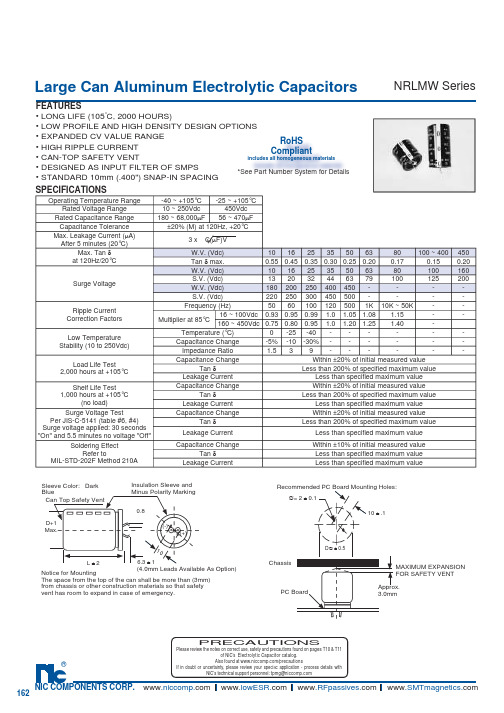
Large Can Aluminum Electrolytic CapacitorsFEATURES• LONG LIFE (105°C, 2000 HOURS)• LOW PROFILE AND HIGH DENSITY DESIGN OPTIONS • EXPANDED CV VALUE RANGE• HIGH RIPPLE CURRENT• CAN-TOP SAFETY VENT • DESIGNED AS INPUT FILTER OF SMPS• STANDARD 10mm (.400") SNAP-IN SPACING NRLMW SeriesSPECIFICATIONSNotice for MountingThe space from the top of the can shall be more than (3mm) from chassis or other construction materials so that safety vent has room to expand in case of emer g en c y.Sleeve Color: Dark BlueCan Top Safety VentInsulation Sleeve and Minus Polarity Marking(4.0mm Leads Available As Option)D+1Max.L ± 26.3 ± 10.810(-)(+)MAXIMUM EX P AN S IONFOR SAFETY VENT Approx. 3.0mmRecommended PC Board Mounting Holes:10 ± .1∅= 2 ± 0.1D ∅ ± 0.5ChassisPC BoardPRECAUTIONSPlease review the notes on correct use, safety and precautions found on pages T10 & T11of NIC’s Electrolytic Capacitor catalog . Operating Temperature Range-40 ~ +105°C -25 ~ +105°C Rated Voltage Range 10 ~ 250Vdc 450Vdc Rated Capacitance Range 180 ~ 68,000µF 56 ~ 470µF Capacitance Tolerance ±20% (M) at 120Hz, +20°CMax. Leakage Current (µA)After 5 minutes (20°C)3 x C(µF)VMax. Tan δat 120Hz/20°CW.V. (Vdc)10162535506380100 ~ 400450Tan δ max.0.550.450.350.300.250.200.170.150.20Surge VoltageW.V. (Vdc)10162535506380100160S.V. (Vdc)132032446379100125200W.V. (Vdc)180200250400450----S.V. (Vdc)220250300450500----Ripple Current Correction Factors Frequency (Hz)50601001205001K 10K ~ 50K --Multiplier at 85°C16 ~ 100Vdc0.930.950.99 1.0 1.05 1.08 1.15--160 ~ 450Vdc0.750.800.95 1.0 1.20 1.25 1.40-Low Temperature Stability (10 to 250Vdc)Temperature (°C)0-25-40------Capacitance Change -5%-10-30%------Impedance Ratio 1.539------Load Life Test 2,000 hours at +105°C Capacitance ChangeWithin ±20% of initial measured valueTan δLess than 200% of specifi ed maximum valueLeakage Current Less than specifi ed maximum value Shelf Life Test 1,000 hours at +105°C(no load)Capacitance ChangeWithin ±20% of initial measured value Tan δLess than 200% of specifi ed maximum valueLeakage Current Less than specifi ed maximum value Surge Voltage TestPer JIS-C-5141 (table #6, #4)Surge voltage applied: 30 seconds "On" and 5.5 minutes no voltage "Off"Capacitance ChangeWithin ±20% of initial measured value Tan δLess than 200% of specifi ed maximum valueLeakage Current Less than specifi ed maximum value Soldering EffectRefer toMIL-STD-202F Method 210ACapacitance ChangeWithin ±10% of initial measured valueTan δLess than specifi ed maximum value Leakage CurrentLess than specifi ed maximum valueRoHSCompliantincludes all homogeneous materials *See Part Number System for DetailsLarge Can Aluminum Electrolytic Capacitors NRLMW SeriesLarge Can Aluminum Electrolytic CapacitorsNRLMW SeriesNRLMW 471 M 250V 30X35 FRoHS compliant Case Size (mm) Voltage Rating Tolerance Code Capacitance Code SeriesPART NUMBER SYSTEM。
瑞特拉电子产品购买指南说明书
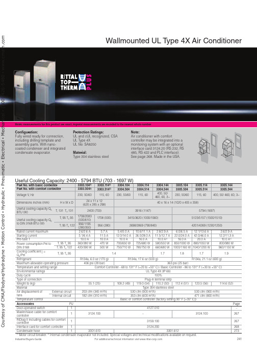
241For additional technical information visit Metric measurements for this product are exact, imperial measurements are rounded to the nearest whole numberUseful Cooling Capacity: 2400 - 5794 BTU (703 - 1697 W)Part No. with basic controller 3303.1042)3303.1142)3304.1043304.1143304.1443305.1043305.1143305.144Part No. with comfort controller 3303.5042)3303.5142)3304.5043304.5143304.5443305.5043305.5143305.544Voltage V , Hz230, 50/60115, 60230, 50/60115, 60400, 50/ 460, 60, 3~230, 50/60115, 60400, 50/ 460, 60, 3~Dimensions inches (mm)H x W x D24 x 11 x 12 (620 x 285 x 298)40 x 16 x 14 (1020 x 405 x 358)Useful cooling capacity Q KBTU (W)T i 131 T a 1312400 (703)3916 (1147)5794 (1697)Useful cooling capacity Q K to DIN 3168 BTU (W)T i 95 T a 951708/2083(500/610)1708 (500)3415/3620 (1000/1060)5123/5157 (1500/1510)T i 95 T a 122956/1195(280/350)956 (280)2698/2869 (790/840)4201/4269 (1230/1250)Rated current maximum 2.6/2.6 A 5.7 A 5.4/5.0 A 10.6/11.1 A 2.8/2.9 A 6.0/6.5 A 12.1/13.6 A 2.6/2.9 A Starting current 5.1/6.4 A 11.5 A 12.0/14.0 A 26.0/28.0 A 11.5/12.7 A 22.0/24.0 A 42.0/46.0 A 12.2/11.3 A Pre-fuse T 10.0 A 10.0 A 10.0 A 16.0 A 10.0 A 1)16.0 A 20.0 A 10.0 A 1)Power consumption Pel toDIN 3168T i 95 T a 95360/380 W 470 W 700/650 W 725/680 W 580/550 W 850/1000 W 880/1050 W 800/980 W T i 95 T a 122420/390 W500 W 750/710 W 780/750 W 660/680 W 1000/1160 W 1040/1200 W 960/1150 W Cooling coefficient j =Q K /PelT i 95 T a 95 1.4 1.7 1.8 1.7 1.9Refrigerant R134a, 6.0 oz (170 g)R134a, 17.6 oz (500 g)R134a, 21.1 oz (600 g)Maximum allowable operating pressure 406 psi (28 bar)363 psi (25 bar)Temperature and setting range Comfort Controller - 68 to 131° F (+20 to +55° C) / Basic Controller - 86 to 131° F (+30 to +55° C)Environmental ratings UL Type 4X (IP 66)Duty cycle 100%Type of connection Plug-in terminal strip Weight lb (kg)55.1 (25)108.2 (49)119.0 (54)110.2 (50)112.4 (51)123.5 (56)114.6 (52)Material Type 304 stainless steelAir displacement offans External circuit 203 cfm (345 m 3/h)530 cfm (900 m 3/h)530 cfm (900 m 3/h)Internal circuit 182 cfm (310 m 3/h)353 cfm (600 m 3/h)471 cfm (800 m 3/h)Temperature control Basic or comfort controller (factory setting 95° F [+35° C])Accessories PU Page Door-operated switch 14127.010–Master/slave cable for comfortcontroller13124.100–3124.100267RiDiag II including cables for comfortcontroller13159.100267Interface card for comfort controller 13124.200268Condensate hose 13301.6103301.6122731) Motor circuit breaker. 2)Internal condensate evaporator not included. Special voltages and technical modifications available on request.Wallmounted UL T ype 4X Air ConditionerCon guration:Fully wired ready for connection, including drilling template and assembly parts. With nano-coated condenser and integrated condensate evaporator.Protection Ratings:UL and cUL recognized, CSA UL Type 4XUL file: SA8250 Material:Type 304 stainless steel Note:Air conditioner with comfortcontroller may be integrated into a monitoring system with an optional interface card 3124.20 (RS 232, RS 485, RS 422 and PLC interface). See page 268. Made in the USA.000C o u r t e s y o f C M A /F l o d y n e /H y d r a d y n e ŀ M o t i o n C o n t r o l ŀ H y d r a u l i c ŀ P n e u m a t i c ŀ E l e c t r i c a l ŀ M e c h a n i c a l ŀ (800) 426-5480 ŀ w w w .c m a f h .c o242For additional technical information visit Metric measurements for this product are exact, imperial measurements are rounded to the nearest whole numberUseful Cooling Capacity: 8706 - 10525 BTU (2550 - 3083 W)Part No. with basic controller 3328.1043328.1143328.1443329.1043329.1143329.144Part No. with comfort controller 3328.5043328.5143328.5443329.5043329.5143329.544Rated operating voltage V , Hz 230, 50/60115, 50/60400, 50/460, 60, 3~230, 50/60115, 50/60400, 50/460, 60, 3~Dimensions inches (mm)H x W x D 65 x 16 x 15 (1650 x 405 x 388)Useful cooling capacity Q K BTU (W)T i 131 T a 1318706 (2550)10525 (3083)Useful cooling capacity Q K to DIN 3168 BTU (W)T i 95 T a 956860/8025 (2000/2350)8538/9392 (2500/2750)T i 95 T a 1224952/5772 (1450/1690)5464/5977 (1600/1750)Rated current max. 7.5 A/9.1 A 14.7 A/17.3 A 2.8 A/3.3 A 8.6 A/10.6 A 17.0 A/22.0 A 3.7 A/3.8 A Start-up current 22.0 A/26.0 A36.0 A/39.0 A6.8 A/7.8 A 21.0 A/21.0 A44.0 A/42.0 A6.8 A/7.6 A Pre-fuse T16.0 A25.0 A 10.0A/10.0 A 1)16.0 A 25.0 A 10.0 A/10.0 A 1)Power consumption Pel to DIN 3168 T i 95 T a 951025/1200 W 1085/1250 W 1050/1275 W 1450/1675 W 1500/1725 W 1425/1625 W T i 95 T a 1221250/1350 W1300/1410 W1275/1525 W1625/2000 W1675/2065 W1675/1975 WCooling coefficient j = Q K /Pel T i 95 T a 951.72.31.92.0RefrigerantR134a, 31.7 oz (900 g)Maximum allowable operating pressure 406 psi (28 bar)Temperature and setting range Comfort Controller - 68 to 131° F (+20 to +55° C) / Basic Controller - 86 to 131° F (+30 to +55° C)Protection rating UL Type 4X (IP 66)Duty cycle 100%Type of connection Plug-in terminal stripWeight lb (kg)176.4 (80)191.8 (87)176.4 (80)183.0 (83)198.4 (90)183.0 (83)MaterialType 304 stainless steelAir displacement of fans External circuit 377 cfm (640 m 3/h)418 cfm (710 m 3/h)Internal circuit324 cfm (550 m 3/h)377 cfm (640 m 3/h)Temperature control Basic or comfort controller (factory setting 95° F [+35° C])Accessories PU Page Door-operated switch14127.010–Master/slave cable for comfort controller13124.100267RiDiag II including cables for comfort controller 13159.100267Interface card for comfort controller 13124.200268Condensate hose13301.6122731)Motor circuit breaker. Special voltages available on request. We reserve the right to make technical modifications.Wallmounted UL T ype 4X Air ConditionerCon guration:Fully wired ready for connection, including drilling template and assembly parts. With nano-coated condenser and integrated condensate evaporator.Protection Ratings: UL and cUL recognized UL Type 4X UL file: SA8250Material:Type 304 stainless steelNote:Air conditioner with comfortcontroller may be integrated into a monitoring system with an optional interface card 3124.200(RS 232, RS 485, RS 422 and PLC interface). See page 268. Made in the USA.C o u r t e s y o f C M A /F l o d y n e /H y d r a d y n e ŀ M o t i o n C o n t r o l ŀ H y d r a u l i c ŀ P n e u m a t i c ŀ E l e c t r i c a l ŀ M e c h a n i c a l ŀ (800) 426-5480 ŀ w w w .c m a f h .c o。
JUNOS M160路由器手册说明书
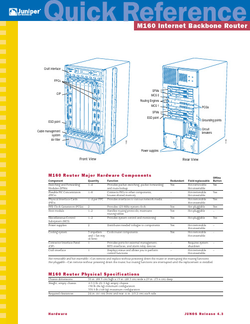
H a r d w a r e J U N O S R e l e a s e 4.3M 160 R o u t e r M a j o r H a r dw a r e C o m p o n e n t s Offline Component Quantity Function Redundant Field-replaceable Button Switching and Forwarding 1–4Provides packet switching, packet forwarding,Yes Hot-removable Yes Modules (SFMs)and route lookup Hot-insertableFlexible PIC Concentrators 1–8Connects PICs to other components,–Hot-removable Yes (FPCs)houses shared memory Hot-insertablePhysical Interface Cards 1–4 per FPC Provides interfaces to various network media –Hot-removable Yes (PICs)Hot-insertablePFE Clock Generators (PCGs)2Provides 125-MHz system clock Yes Hot-pluggable Yes Host module 1–2Handles routing protocols, maintains Yes Hot-pluggable –routing tablesMiscellaneous Control 1–2Provides system control and monitoring Yes Hot-pluggable Yes Subsystem (MCS)Power supplies 2Distributes needed voltages to components Yes Hot-removable –Hot-insertableCooling system 3 impellers Cools router components Yes Hot-removable –and 1 fan tray Hot-insertable(4 fans)Connector Interface Panel 1Provides ports for external management,–Requires system –(CIP)BITS interfaces, and alarm relay devices shutdownCraft interface 1Displays status and allows you to perform –Hot-removable –control functions Hot-insertableHot-removable and hot-insertable —Can remove and replace without powering down the router or interrupting the routing functions.Hot-pluggable —Can remove without powering down the router, but routing functions are interrupted until the replacement is installed.M 160 R o u t e r P hys i c a l S p e c i fi c a t i o n sChassis dimensions 35 in. (88.9 cm) high x 19 in. (48.3 cm) wide x 29 in. (73.6 cm) deepWeight, empty chassis 113.5 lb (51.5 kg) empty chassis190 lb (86 kg) minimum configuration370.5 lb (168 kg) maximum configurationRequired clearances 24 in. (61 cm) front and rear; 6 in. (15.2 cm) each side1165Craft interfaceFPCsCIP ESD point Cable management system Air filter 1166PC G 0SF M 0SF M 1M C S 0R E 0R E 1M C S 1SF M 2SF M 3PC G 1PCGs Routing Engines MCS 0MCS 1SFMs SFMs Circuitbreakers Grounding points ESD pointPower suppliesFront View Rear ViewM160R o u t e r P o w e r S y s t e m S p e c i fi c a t i o n sType DC power only; 2600 W max output; nonisolatedDC input voltage Nominal; –48 VDC to 60 VDCInput DC current rating65 A @ –48 VOutput voltages+48 V @ 8 A (cooling system); +8 V @ 6 A (bias); –48 V @ 60 APower and grounding cables 4 A WG wire cables with dual 1/4–20 UNC terminal studs @ 0.625 in. (15.86 mm)M160R o u t e r L E D sComponent LED LocationSFMs Green OK SFM faceplateAmber FAILFPCs Green OK Craft interfaceRed FAILPICs 1 LED with 4 states: Red, Green, Amber, Off PIC faceplatePCGs Blue MASTER PCG faceplateGreen OKAmber FAILHost module Green MASTER Craft interfaceGreen ONLINERed OFFLINEMCS Blue MASTER MCS faceplateGreen OKAmber FAILPower supplies Green CB ON Power supply faceplateBlue OUTPUT OKAmber NO AIRFLOWAmber CB OFFAlarm LEDsRed alarm Large circular red Craft interfaceYellow alarm Large triangular amber Craft interfaceEthernet LEDs10-Mbps link Yellow CIP100-Mbps link Green CIPTa k i n g C o m p o n e n t s O ffl i n eComponent ProcedureFPC 1. Press the offline button located above the FPC on the craft interface.2. Press and hold the button until the red FAIL LED lights (about 5 seconds).PIC 1. Press the PIC offline button.2. Press and hold the button until the PIC LED lights red (about 5 seconds). For an FPC1, the PIC offline button is locatedon the FPC. For an FPC2, the PIC offline button is located on the PIC faceplate.SFM 1. Press the OFFLINE button on the SFM faceplate.2. Press and hold the button until the red FAIL LED lights (about 5 seconds).PCG 1. Press the OFFLINE button on the PCG faceplate.2. Press and hold the button until the red FAIL LED lights (about 3 seconds).T aking the master PCG offline causes the FPCs and SFMs to power down and restart with the other PCG selected asmaster. The forwarding and routing functions are interrupted during this process. T aking the backup PCG offline does notaffect the functioning of the router.You can determine which PCG is functioning as master in one of two ways:s Check the blue MASTER LED on the PCG faceplate. If this LED is on steadily, the PCG is functioning as master.s To display which PCG is functioning as master, use the following CLI command:user@host> show chassis clocksHost module You take the host module (the Routing Engine and the MCS) offline as a unit. Before you replace a Routing Engine or an MCS, you take the host module offline. The host module is hot-pluggable.Normally, if two host modules are installed in the router, HOST0 functions as the master and HOST1 as the backup. Youcan remove the backup host module (or either of its components) without interrupting the functioning of the router. If youtake the master host module offline, the router reboots and the backup host module becomes the master. If the router hasonly one host module, taking it offline causes the router to shut down.To take the host module offline:1. Determine whether the host module is functioning as master or as backup, using one of the following two methods:s Check the host module LEDs on the craft interface. If the green MASTER LED is lit, the corresponding host moduleis functioning as master.s Display which host module is functioning as the master:user@host> show chassis routing-engine2. If the host module is master, switch the host module to backup:user@host> request chassis routing-engine master switchWhen you switch the host module from master to backup, the functioning of the router is interrupted for up to severalminutes as the system reboots and the new master host module downloads software to the SFMs.S ys t e m A r c h i t e c t u r eThe router has two major architectural components: the Routing Engine, which provides Layer 3 routing services and network management; and the Packet Forwarding Engine, which provides packet switching, route lookups, and packet forwarding. TheRouting Engine and Packet Forwarding Engine operate independently, but constantly communicate through a 100-Mbps link, as illustrated in the figure at the right.Pa c k e t F l o w t h r o u g h t h e Pa c k e tF o r wa r d i n g E n g i n eTo ensure efficient packet flowthrough the system, data packetforwarding is handled by ASICs onthe hardware components. The figureat the right shows the sequence ofpacket flow through the PacketForwarding Engine.R o u t i n g E n g i n e A r c h i t e c t u r eThe Routing Engine handles all the routing protocolprocesses as well as processes controllinginterfaces, router components, systemmanagement, and user access. These processes runon top of a kernel that interacts with the PacketForwarding Engine.C o n t r o l Pa c k e t H a n d l i n gThe Routing Engine constructs and maintains routingtables, and derives a table of active routes, called the forwarding table, from the routing tables. The forwardingtable is then copied into the Packet Forwarding Engine.Packet ForwardingEngineRouting Engine1244 PacketsinPacketsout100-Mbps link1234DistributedBufferManagerSFMRoutingEngineInternetProcessor IIPacketDirectorFPCI/OManagerPacket inPacket outPICControllerMidplaneJUNOSsoftwareSystemmanagementprocessesRoutingprotocolsControlfunctions System processesOperating systemKernelIntel-based PCI platform1164PacketsinPacketsoutPacket ForwardingEngineForwarding tableForwarding tableupdatesRouting protocolpackets from networkRouting EngineRouting protocolprocess124G e n e r a l S a fe t y G u i d e l i n e ss Only trained and qualified personnel should install or replace the router.s Perform only the procedures described in the M160 Internet Backbone Router Hardware Installation Guide. Other services should be performed by authorized service personnel only.s For protection against shock hazard, verify that all power cables are disconnected before servicing the router.s Before installing the router, read the guidelines in the “Prepare the Site” section of the M160 Internet Backbone Router Hardware Installation Guide to make sure that the site meets power, environmental, and clearance requirements for the router.s Manually installing the router requires three people to lift the chassis and a fourth person to secure the mounting screws. Before lifting the chassis, remove components and attach the installation lifting handle as described in the M160 Internet Backbone Router Hardware Installation Guide. To prevent injury, keep your back straight and lift with your legs, not your back. Do not attempt to lift the chassis with the handles on the power supplies.s Do not work on the router or connect or disconnect cables during electrical storms.s Never install electrical jacks in wet locations unless the jacks are specifically designed for wet environments.s Operate the router only when the grounding wire is connected.s Use copper conductors only.s Avoid touching uninsulated electrical wires or terminals that have not been disconnected from their power source. Doing so could cause electrical shock.s Do not open or remove chassis covers or sheet metal parts when instructions are not provided in the M160 Internet Backbone Router Hardware Installation Guide. Doing so could cause severe electrical shock.s Do not push or force any objects through any of the openings in the chassis frame. Doing so could result in electrical shock or fire.s Avoid spilling liquid into the router chassis or onto any router components. Doing so could cause electrical shock or damage the router.s Before working on equipment that is connected to power lines, remove jewelry, including rings, necklaces, and watches. Metal objects heat up when connected to power and ground and can cause serious burns or weld the metal object to the terminals.s Failure to observe these safety warnings could result in serious physical injury.A g e n c y A p p r ov a l sCategory ApprovalSafety s CSA C22.2 No. 950s UL 1950s EN 60950, Safety of Information Technology Equipments EN 60825-1 Safety of Laser Products–Part 1: Equipment Classification, Requirements and User’s Guides EN 60825-2 Safety of Laser Products–Part 2: Safety of Optical Fibre Communication SystemsEMI s AS 3548 Class A (Australia)s EN 55022 Class A emissions (Europe)s FCC Class A (USA)s VCCI Class A (Japan)Immunity s EN 61000-3-2 Power Line Harmonicss EN 61000-4-2 ESDs EN 61000-4-3 Radiated Immunitys EN 61000-4-4 EFTs EN 61000-4-5 Surges EN 61000-4-6 Low Frequency Common Immunitys EN 61000-4-11 Voltage Dips and SagsNEBS Designed to meet the following standards:s GR-63-Core: NEBS, Physical Protections GR-1089-Core: EMC and Electrical Safety for Network Telecommunications Equipments SR-3580 NEBS Criteria Levels (Level 3 Compliance)ETSI s ETS-300386-2 Switching Equipmentw w w.j u n i p e r.n e t For support issues, contact the Juniper Networks Technical Assistance Center (JTAC) at 1-888-314-JTAC(within the United States) or 408-745-2121 (from outside the United States). For other contactinformation, refer to /contactus.html.Juniper Networks is a registered trademark of Juniper Networks, Inc. Internet Processor, Internet Processor II, JUNOS, JUNOScript, M5, M10, M20, M40, andM160 are trademarks of Juniper Networks, Inc. All other trademarks, service marks, registered trademarks, or registered service marks may be the property oftheir respective owners. All specifications are subject to change without notice. Copyright © 2001, Juniper Networks, Inc. All rights reserved. Printed in USA.。
卡洛·加华齐控制系统 WM20 三相系统电能分析仪说明书

Compatible accessory modules
Type Digital outputs
Communication
Power supply (H or L) [kV]
-
4
4 4 4
Measurement inputs [kV]
4
-
4 4 4
Digital outputs [kV]
4
4 4 4
Serial port [kV]
4
4 4 NP
Ether-
Key • NP: combination not possible • 4: 4 kV rms insulation (EN 61010-1, IEC 60664-1, overvoltage category III, pollution degree 2, double insulation on
ules and manage up to two alarms.
Accessory module with two digital outputs. Expands main unit capacity, specifically allowing you to:
Transmit pulses proportional to energy consumption Control digital outputs (static or relay according to the module)
• Specific software. WM20 can be configured and measurements viewed from UCS configuration software (CARLO GAVAZZI). The software and subsequent updates are free.
夏普M160M205零件手册中文_部分2

O第二纸盒给纸组件 (AR-M205)O第二纸盒给纸组件AR-RP6 MODEL目 录为确保安全性、可靠性,更换部品务必使用正规品。
指定的部品。
本手册仅供维修人员进行售后服务用,本手册内容如有更改,恕不通告。
SHARP CORPORATION部 品 手 册1234■外观给纸组件输送组件包装及附属品索引数码复合机选购件双面原稿输送器(RSPF)1外观1外观3输送组件3输送组件4包装及附属品4包装及附属品AR-D24单层纸盒AR-D25双层纸盒MODEL目 录为确保安全性、可靠性,更换部品务必使用正规品。
指定的部品。
本手册仅供维修人员进行售后服务用,本手册内容如有更改,恕不通告。
SHARP CORPORATION部 品 手 册123456■单层纸盒外观 (AR-D24)单层纸盒给纸组件 (AR-D24)双层纸盒外观 (AR-D25)双层纸盒给纸组件 (AR-D25)250页纸盒组件包装材料及附属品索引数码复合机选购件进纸组件1单层纸盒外观 (AR-D24)1单层纸盒外观 (AR-D24)2单层纸盒给纸组件 (AR-D24)2单层纸盒给纸组件 (AR-D24)4双层纸盒给纸组件 (AR-D25)4双层纸盒给纸组件 (AR-D25)5250页纸盒组件5250页纸盒组件6包装材料及附属品6包装材料及附属品■索引– 12 –COPYRIGHT © 2003 BY SHARP CORPORATION版权所有 翻印必究夏普办公设备(常熟)有限公司上海经营部中国上海浦东新金桥路28号新金桥大厦1601室 2003年10月中国印刷。
WND60P16W 标准反向恢复功率诱导器数据手册说明书
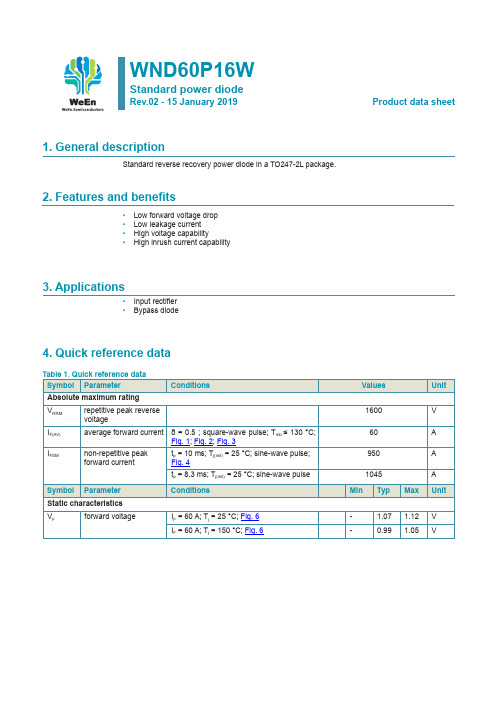
WND60P16WStandard power diodeRev.02 - 15 January 2019Product data sheet1. General descriptionStandard reverse recovery power diode in a TO247-2L package.2. Features and benefits• Low forward voltage drop• Low leakage current• High voltage capability• High inrush current capability3. Applications• Input rectifier• Bypass diode4. Quick reference data5. Pinning information6. Ordering information7. Marking8. Limiting values Table 5. Limiting values9. Thermal characteristics10. Characteristics00.51 1.5224487296120V F (V)I F (A)aph15-006(1)(3)(2) V o = 0.792 V; R s = 0.0043 Ω (1) T j= 150 °C; typical values(2) T j = 150 °C; maximum values (3) T j = 25 °C; maximum valuesFig. 6. Forward current as a function of forward voltage11. Package outline12. Legal informationData sheet status[1lease consult the most recently issued document before initiating or completing a design.[2]The term 'short data sheet' is explained in section "Definitions".[3]The product status of device(s) described in this document may havechanged since this document was published and may differ in case ofmultiple devices. The latest product status information is available onthe Internet at URL .DefinitionsDraft — The document is a draft version only. The content is still under internal review and subject to formal approval, which may result in modifications or additions. WeEn Semiconductors does not give any representations or warranties as to the accuracy or completeness of information included herein and shall have no liability for the consequences of use of such information.Short data sheet — A short data sheet is an extract from a full data sheet with the same product type number(s) and title. A short data sheet is intended for quick reference only and should not be relied upon to contai n detailed and full information. For detailed and full information see the relevant full data sheet, which is available on request via the local WeE n Semiconductors sales office. In case of any inconsistency or conflict with the short data sheet, the full data sheet shall prevail.Product specification — The information and data provided in a Product data sheet shall define the specification of the product as agreed between WeEn Semiconductors and its customer, unless WeEn Semiconductors and customer have explicitly agreed otherwise in writing. In no event however, shall an agreement be valid in which the WeEn Semiconductors productis deemed to offer functions and qualities beyond those described in the Product data sheet.DisclaimersLimited warranty and liability — Information in this document is believedto be accurate and reliable. However, WeEn Semiconductors does notgive any representations or warranties, expressed or implied, as to the accuracy or completeness of such information and shall have no liability for the consequences of use of such information. WeEn Semiconductors takes no responsibility for the content in this document if provided by an information source outside of WeEn Semiconductors.In no event shall WeEn Semiconductors be liable for any indirect, incidental, punitive, special or consequential damages (including - without limitation -lost profits, lost savings, business interruption, costs related to the removal or replacement of any products or rework charges) whether or not such damages are based on tort (including negligence), warranty, breach of contract or any other legal theory.Notwithstanding any damages that customer might incur for any reason whatsoever, WeEn Semiconductors’ aggregate and cumulative liability towards customer for the products described herein shall be limited in accordance with the Terms and conditions of commercial sale of WeEn Semiconductors.Right to make changes — WeEn Semiconductors reserves the right to make changes to information published in this document, including without limitation specifications and product descriptions, at any time and without notice. This document supersedes and replaces all information supplied prior to the publication hereof.Suitability for use — WeEn Semiconductors products are not designed, authorized or warranted to be suitable for use in life support, life-criticalor safety-critical systems or equipment, nor in applications where failureor malfunction of an WeEn Semiconductors product can reasonablybe expected to result in personal injury, death or severe property o r environmental damage. WeEn Semiconductors and its suppliers accept no liability for inclusion and/or use of WeEn Semiconductors products in such equipment or applications and therefore such inclusion and/or use is at th e customer’s own risk.Quick reference data — The Quick reference data is an extract of th e product data given in the Limiting values and Characteristics sections of this document, and as such is not complete, exhaustive or legally binding. Applications — Applications that are described herein for any of these products are for illustrative purposes only. WeEn Semiconductors makesno representation or warranty that such applications will be suitable for the specified use without further testing or modification.Customers are responsible for the design and operation of their applications and products using WeEn Semiconductors products, and WeEn Semiconductors accepts no liability for any assistance with applications or customer product design. It is customer’s sole responsibility to determine whether the WeEn Semiconductors product is suitable and fit for the customer’s applications and products planned, as well as for the planned application and use of customer’s third party customer(s). Customers shoul d provide appropriate design and operating safeguards to minimize the risks associated with their applications and products.WeEn Semiconductors does not accept any liability related to any default, damage, costs or problem which is based on any weakness or defaultin the customer’s applications or products, or the application or use by customer’s third party customer(s). Customer is responsible for doing al l necessary testing for the customer’s applications and products using WeEn Semiconductors products in order to avoid a default of the applicationsand the products or of the application or use by customer’s third party customer(s). WeEn does not accept any liability in this respect.Limiting values — Stress above one or more limiting values (as defined in the Absolute Maximum Ratings System of IEC 60134) will cause permanent damage to the device. Limiting values are stress ratings only and (proper) operation of the device at these or any other conditions above thosegiven in the Recommended operating conditions section (if present) or the Characteristics sections of this document is not warranted. Constant o r repeated exposure to limiting values will permanently and irreversibly affect the quality and reliability of the device.No offer to sell or license — Nothing in this document may be interpreted or construed as an offer to sell products that is open for acceptance or the grant, conveyance or implication of any license under any copyrights, patents or other industrial or intellectual property rights.Export control — This document as well as the item(s) described herein may be subject to export control regulations. Export might require a prior authorization from competent authorities.Non-automotive qualified products — Unless this data sheet expressl y states that this specific WeEn Semiconductors product is automotive qualified, the product is not suitable for automotive use. It is neither qualifie d nor tested in accordance with automotive testing or application requirements. WeEn Semiconductors accepts no liability for inclusion and/or use of non-automotive qualified products in automotive equipment or applications.In the event that customer uses the product for design-in and use in automotive applications to automotive specifications and standards, customer (a) shall use the product without WeEn Semiconductors’ warranty of the product for such automotive applications, use and specifications, and (b) whenever customer uses the product for automotive applications beyond WeEn Semiconductors’ specifications such use shall be solely at customer’s own risk, and (c) customer fully indemnifies WeEn Semiconductors forany liability, damages or failed product claims resulting from customer design and use of the product for automotive applications beyond WeEn Semiconductors’ standard warranty and WeEn Semiconductors’ product specifications.]PTranslations — A non-English (translated) version of a document is for reference only. The English version shall prevail in case of any discrepancy between the translated and English versions.TrademarksNotice: All referenced brands, product names, service names and trademarks are the property of their respective owners.13. Contents1. General description (1)2. Features and benefits (1)3. Applications (1)4. Quick reference data (1)5. Pinning information (2)6. Ordering information (2)7. Marking (2)8. Limiting values (3)9. Thermal characteristics (5)10. Characteristics (6)11. Package outline (7)12. Legal information (8)13. Contents (10)© WeEn Semiconductors Co., Ltd. 2019. All rights reservedFor more information, please visit: Forsalesofficeaddresses,pleasesendanemailto:**************************** Date of release: 15 January 2019。
水星MW315R详细资料大全
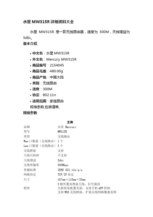
水星MW315R详细资料大全
水星MW315R是一款无线路由器,速度为300M,天线增益为5dbi。
基本介绍
•中文名:水星MW315R
•外文名:Mercury MW315R
•商品编号:2154045
•商品毛重:480.00g
•商品产地:中国大陆
•类别:无线路由
•速度:300M
•协定:802.11n
•适用范围:家庭路由
规格参数,包装清单,
规格参数
主体
品牌水星 Mercury
型号MW315R
类型无线路由
Wan口数量(无线路由)1个
Lan口数量(无线路由)3个
无线桥接支持
天线可拆卸不支持
天线增益5dbi
无线传输率300Mbps
传输标准IEEE 802.11b/g/n
网路协定TCP/IP协定
尺寸167mm×118mm×33mm
特性3根外置高增益天线,信号强劲
全新简易配置页面,支持手机APP控制
支持WDS无线桥接,扩展无线网路覆蓋范围
主体
支持IP频宽控制,合理分配网路资源包装清单
路由器 x1、适配器 x1、说明书 x1。
灯具153

UL 153的範圍一、適用於:1.UL153之最新版本為發行於2002年3月25日之12版本,最新修訂日期為2004年2月18日2.UL153適用於以照明為主要用途的可移動燈飾,附有電源線及插頭,可供插接於120伏之電源插座。
3.適用於以照明或裝飾為主要用途之燈具,如小夜燈、鏡燈及新奇的燈二、不適用於:1.聖誕及裝飾裝備2.電子標示牌3.戶外泛光探照燈4.舞台燈具及攝影燈具機械結構一、裝配及包裝1.帶電部份不可被觸及2.所有電路連接處需在工廠內完成3.應有固線器4.如適用,應附有裝配說明書5.穿過節與節之間的電線,如非於下列情況下,裝配時不可轉動多於360度6.套管內徑大過或等於12.7毫米7.於三寸內不會轉多於一圈8.導體涉及已被固定並不可被觸及的電路連接處,同時配有固線器二、燈罩結構1.需可靠地維持其尺寸2.以慢燃的物料製成3.如有下列其中一種結構,需進行異常操作測試。
4.可調校或可彎曲的燈罩,並可調至貼近支撐表面5.有多個燈罩,而其中的燈罩能直接照射其他燈罩6.燈罩能摺起以致氣流受阻三、外殼及開孔1.外殼之原材料可為金屬、玻璃、陶、瓷或塑料2.包圍着所有帶電部份及零件﹝如接合點、變壓器、電容、鎮流器或帶電部份。
3.塑料外殼需符合UL746B及UL746C要求﹝於正常使用時不會變形的裝飾部份除外﹞4.不可鋒利致能構成使用者於正常使用及維修期間被割傷5.開孔不可容許可觸及性探頭接觸帶電部份或其他電子零件6.外殼可以金屬片、擠出金屬、鑄金屬、玻璃、瓷或塑料製成7.開孔不能影響外殼之強度及堅硬度8.去水孔之直徑應大於1/8寸9.距離安裝表面少於半寸的開孔均被視為安裝孔10.每個通氣孔之面積應小於1.5平方寸。
11.所有通氣孔之面積總和應小於外殼總面積之百分之十五。
四、電線管道及套管1.電線管道不可有銳邊2.電線管道需防止電線接觸可轉動的部份3.金屬螺絲及自攻螺絲於電線管道上不可露出多於4.8毫米4.如導線會穿過金屬片,需配有絕緣襯套5.厚度多於0.25毫米的玻璃纖維套管可用作襯套6.熱縮管不可用作防止被割斷的襯套7.襯套需被固定8.不可使用橡膠襯套9.不可有缺口或裂縫10.以最小0.51毫米厚之金屬製成11.金屬套管的最小厚度為1毫米12.用於E26或以下燈頭的套管,應以最小厚度為1.27毫米的慢燃物料製成(慢燃物料:如聚苯乙烯、聚氯乙烯、木、尼龍及棉)五、零件安裝1.零件如燈頭、保險絲或開關,需牢固地安裝於燈具上,並需防止其轉動或移位六、固線器1.防止拉力傳達至接線端或內部線2.防止因拉動、推入、折彎或扭動電線而產生之應力傳達至接線端或內部零件3.以金屬夾子作固線器的SPT-2線應附有額外的絕緣層作機械性保護4.電線打結可作為固線器5.固線器能觸及的地方不可有尖邊電子結構一、電子間距的要求1.不適用於已獲認證的零件之非絕緣帶電部份,如燈頭及開關2.不適用於二級電路的非絕緣帶電部份及其他無電通過的金屬部份3.UL153的電子間距要求:a.接線設備的帶電部份b.接線設備的絕緣物料c.接線設備的安裝螺絲d.接線設備中的不帶電金屬部份e.可移動燈具的不帶電金屬部份f.適用的間距g.不適用的間距4.氣間及表面間距應大於3.2毫米5.綫路板上不同零件之間距應大於3.2毫米6.綫路板上導體之間距應大於1.2毫米二、電線及內部線1.電線之額定電壓、電流或溫度應最小相等於正常使用時將承受之數值2.導體應為18號或以上3.小於18號但大於24號的導體可應用於2級電路4.如符合下列情況,22號或24號之導體可供使用:a.引綫被完全包圍,並不使用於轉節b.長度少於6寸c.絕緣厚度應大於1/32寸d.應用於變壓器或電路的次級線圈5.附在可移動部份的內部線應屬絞合類,需被固定而其絕緣層不可被割斷或磨損6.如電源線被推回外殼內時能觸及熱表面、尖邊或轉動部份,則必需以機械方法防止7.由離開燈具起至插頭面,電源線之最小長度應為1.5米三、極性及識別1.兩線插頭的大插刀或三線接地插頭需連接至接地導體2.愛廸生燈頭的螺絲殼應連接電源線的接地導體3.開關、保險絲或其他保護設施不得連接至插頭的接地導體四、接地及搭接1.如電源線配有三條導體,則所有傳導性的部份均需連接至插頭的接地針2.接地或搭接系統的連貫性不可單靠焊錫或熱塑性塑料的尺寸原整性維持3.彈簧或齒狀墊圈可賴以維持地線連接的可靠性4.薄片金屬螺絲不可用於固定搭接或接地線五、插頭1.插頭應配有極性的兩線平衡插刀或為三線接地型2.額定值應為可供接於125伏,15安培的配置六、電源線1.常見之電源線為SPT-2線2.電源線應不小於18號3.電源線最小應長1.5米4.SPT-1線不能用作電源線七、燈頭1.備有外露接線端的燈頭,其接線端應位於永久性屏障或相類結構的後方2.三通開關的燈頭只可以底部向下的形式安裝3.接線端子不可用作兩針燈的燈頭八、開關1.開關應連接至供應電路沒有接地的一端﹝即火線﹞2.可移動燈具的開關,其最小電流額定值應相等於其所控制的總電流量3.應用於鎢絲燈的開關,需具備T或L額定值4.如非上述額定值,其所需之額定值將如下:a.配E12燈頭開關的最小額定值應為其總控制電流的五倍﹝如最大負重為0.5安培,開關之最小額定值為2.5安培﹞b.其他鎢絲燈開關的最小額定值應為其總控制電流的六倍﹝如最大負重為0.5安培,開關之最小額定值為3安培﹞c.螢光燈開關的最小額定值應為其總控制電流的兩倍﹝如最大負重為0.5安培,開關之最小額定值為1安培﹞九、連接處及接線1.電線於焊接前需勾入端子2.電路連接時需提防焊錫冷流3.線尾端子及線帽需按其額定值使用4.如連接點可被移動,需使用鎖定墊圈特殊要求一、鹵素燈1.單邊雙腳燈泡只限用於低壓2.保護器,燈泡隔離器及紫外光過濾器可被製成單一部份3.保護器,燈泡隔離器及紫外光過濾器應被固定4.配有雙層燈泡殼的單邊鹵素燈不需配備保護器或紫外光過濾器二、鹵素火炬燈1.保護器需置於火炬座地燈之燈間隔上方2.紫外光過濾器應以石灰鈉玻璃或聚合物料製成,其傳輸特性需符合下表內之數值:3.保護器應以下列物料製成:a.最小直徑為1.5毫米的電鍍或塗漆線b.最小0.41毫米厚的金屬c.瓷或陶d.熱阻玻璃 :如強化、退火或硼矽酸鹽玻璃如燈具的功率大於100瓦,最小厚度應為3.2毫米如燈具的功率少於100瓦,最小厚度應為2.4毫米4.保護器上不得有任何對角線長度或直徑大於3.2毫米的小孔三、火炬燈保護器1.如符合下列情況則可免除保護器:a.燈泡備有雙層燈泡殼b.符合熱流密度測試c.配有合適的燈泡d.燈具標上燈泡的功率、形狀、標誌及槪述圖畫e.如燈泡種類並不常見,應備有說明書指示用者如何從經銷商或生產商購買燈泡2.以下列形式固定:a.機械式b.旋轉及閉鎖式c.彈簧夾式3.防止探針接觸燈泡隔離器或燈泡:a.直徑38.1毫米的圓頭探針從任何角度插入保護器b.10毫米厚,35毫米闊的平片探針以 45度插入保護器4.保護器及燈泡隔離器的最小間距:a.由燈泡隔離器中心至燈泡為76毫米b.由燈炮隔離器未端至燈泡為60毫米5.具玩具價值或玩具造型的燈具:a.如燈具有可供八歲或以下小童把玩的可拆除部份,則必須遵從聯邦法例中的兒童玩物章節﹝例:燈具上有可拆除的絨毛洋娃娃﹞b.玩具造型燈具需符合15度穩定度測試6.可攜櫃燈:a.電源線長度最少應為10尺b.插頭及插座的額定值不得少於15安培,如備有電流過大保護裝備則不受此限c.用於次度電路或低壓電路的插頭及插座不可為NEMA型1-15、1-15P、5-15和5-20d.低壓接線不需配有電流過大保護設備7.濕地使用燈具:a.標明適合濕地使用的燈具需符合淋雨及灑水測試b.其結構需防止帶電部份積水,而未被確認為適合於有水時使用的電子零件或導體亦不可被沾濕c.塑料製成的防水保護屏需為具特定防紫外光值的物料d.去水孔之最小直徑為3.2毫米e.如燈泡種類並不常見,應備有說明書指示用者如何從經銷商或生產商購買燈泡f.任何暴露於燈具外的電源線應為SJ、SJO、SJT或具相同功效,並標有“W”記號g.電線最大長度為50尺h.適合濕地使用燈具的可觸及及金屬部份, 如遇電路故障時有機會帶電,則必須配備附有接地線的插頭I.配備方便插座的可移動燈具需附有自動開關蓋子j.適合濕地使用的燈具應具甲級接地故障電路中斷及水線斷路保護設施k.燈頭的螺絲殼不得以未經電鍍的鋁材製成l.開關的位置應可避免水份進入開關或外殼n.結構內的絕緣體不可具吸收特性安全測試一、溫升測試1.樣品將置於正常使用位置2.燈罩和裝飾部份調校至不同位置以達至產生最高溫升的效果3.如有可調校臂,燈罩則應調校至靠近支撐表面,但距離需大於6寸(152mm)4.表面溫度需以熱電偶量度5.線圈溫度需以電阻差方法量度6.各部份的量度溫度﹝於校正至室溫25度情況下﹞不得超過美國和加拿大標準的限制7.以最大瓦數的燈泡持續操作直至溫度穩定8.如遇下列情況,量度之溫度即被視為穩定:a.運作達最少7.5小時或b.測試持續3小時後,在3個相差半小時的連續讀數內,溫差改變少於1度而溫度沒有持續上升的趨勢9.用作裝飾用途的塑膠料不應溶化和變形10.下列為一般容易於溫升測試中過熱的部份:a.(表面溫度(燈泡除外 )) 90°Cb.調校/接觸部份 :(木 /塑料/ 玻璃/金屬) 90/85/70/50 °Cc.(絕緣物料) 按照額定值d.(變壓器 /鎮流器線圈)按照額定值e.(內部線) 按照額定值f.(電木燈頭) 150 °Cg.(燈頭紙襯墊) 150 °C h.(測試/安裝表面) 90 °C二、異常操作測試﹝可調校或可彎曲燈罩﹞1.測試方法 – 將可調校或可彎曲的燈罩調至貼近支撐表面2.以最大額定功率運作達7小時3.在軟木板上放上白色薄紙,並把燈罩調至緊靠同一平面4.用單層布覆蓋樣本並持續操作5.測試進行中及完成後,不應:a.金屬部份燃燒或溶化b.在測試樣本之下、之下或附近的物料燃燒c.暴露可引致觸電的部份d.在耐壓測試中被擊穿三、零件故障測試1.測試方法 - 關閉或打開電子零件,如電容,整流器, 電晶體或相類零件2.以最大額定功率運作達7小時3.放在沒有接合位的軟木上,並用薄紙蓋着4.連接不帶電金屬部份至3安培的不可恢復的保險絲:a.接地處 - 如屬接地型插頭b.中性導電體 - 如非接地型插頭5.用單層布覆蓋樣本並持續操作6.測試進行中及完成後,不應:a.金屬部份燃燒或溶化b.在測試樣本之下、之下或附近的物料燃燒c.暴露可引致觸電的部份d.在耐壓測試中被擊穿四、異常操作測試 - 啟動器短路測試1.只適用於配有非手動啟動器或P級鎮流器的螢光燈2.以額定電壓及燈泡運作3.把啟動器短路,並以單層布輕輕蓋着燈具,連續操作7小時4.測試進行中及完成後,不應:a.金屬部份燃燒或溶化b.在測試樣本之下、之下或附近的物料燃燒c.暴露可引致觸電的部份d.在耐壓測試中被擊穿五、穩定度測試1.測試方法 - 將玻璃裝飾或燈罩安裝在燈具後,把樣本放在8度斜台上,並以最容易傾倒的放置方式測試2.玩具造型燈具之測試斜度為15度3.火炬鹵素燈於傾斜12度之平面上不得傾翻4.表面溫度大於90度的燈具需符合15度穩定度測試5.燈具於測試期間不可翻倒六、拉力測試1.於接線端附近把電線的導體割斷2.將35磅之砝碼懸掛於電線上1分鐘3.測試後:a.電線之絕緣層不得損壞b.固線器不可從外殼的出線口滑出c.黏合固線器不可沿電線滑動d.電線移位不可多於1.6毫米七、接地連續性測試1.利用25安培電流、60赫和少於6伏的無負載電壓來決定樣本接地處及任何可接觸金屬部份之間的電阻值2.接地處及任何需接地金屬部份之間的電阻值不應高於0.1歐姆3.並非用於保護帶電部分的裝飾部分不需測試八、耐壓測試1.UL153 - 1200伏,40-70赫﹝CSA C22.2 No. 12 - 60赫﹞a.900伏 - 沒有變壓器的白光燈b.1000伏 + 2 x 額定電壓 – 沒有變壓器的螢光燈c.1000伏 + 2 x 初級線圈最大額定電壓 – 配備二級變壓器的燈具2.時間:1分鐘3.測試電壓施於:a.帶電部份及可觸及部份b.帶電部份及次級線路c.一級及次級線圈d.一級線圈及外殼e.不可出現被擊穿或跳火情況九、洩漏電流測試1.在外露的不帶電金屬部份與接地腳之間,以並聯方式接上1500歐姆電阻和0.15 x 10⁻⁶法拉電容。
- 1、下载文档前请自行甄别文档内容的完整性,平台不提供额外的编辑、内容补充、找答案等附加服务。
- 2、"仅部分预览"的文档,不可在线预览部分如存在完整性等问题,可反馈申请退款(可完整预览的文档不适用该条件!)。
- 3、如文档侵犯您的权益,请联系客服反馈,我们会尽快为您处理(人工客服工作时间:9:00-18:30)。
Large Can Aluminum Electrolytic Capacitors
FEATURES
• LONG LIFE (105°C, 2000 HOURS)
• LOW PROFILE AND HIGH DENSITY DESIGN OPTIONS • EXPANDED CV VALUE RANGE
• HIGH RIPPLE CURRENT
• CAN-TOP SAFETY VENT • DESIGNED AS INPUT FILTER OF SMPS
• STANDARD 10mm (.400") SNAP-IN SPACING NRLMW Series
SPECIFICATIONS
Notice for Mounting
The space from the top of the can shall be more than (3mm) from chassis or other construction materials so that safety vent has room to expand in case of emer g en c y.
Sleeve Color: Dark Blue
Can Top Safety Vent
Insulation Sleeve and Minus Polarity Marking
(4.0mm Leads Available As Option)
D+1Max.
L ± 2
6.3 ± 1
0.8
10
(-)
(+)
MAXIMUM EX P AN S ION
FOR SAFETY VENT Approx. 3.0mm
Recommended PC Board Mounting Holes:
10 ± .1
∅= 2 ± 0.1
D ∅ ± 0.5
Chassis
PC Board
PRECAUTIONS
Please review the notes on correct use, safety and precautions found on pages T10 & T11
of NIC’s Electrolytic Capacitor catalog . Operating Temperature Range
-40 ~ +105°C -25 ~ +105°C Rated Voltage Range 10 ~ 250Vdc 450Vdc Rated Capacitance Range 180 ~ 68,000µF 56 ~ 470µF Capacitance Tolerance ±20% (M) at 120Hz, +20°C
Max. Leakage Current (µA)After 5 minutes (20°C)
3 x C(µF)V
Max. Tan δat 120Hz/20°C
W.V. (Vdc)10162535506380100 ~ 400450
Tan δ max.0.550.450.350.300.250.200.170.150.20Surge Voltage
W.V. (Vdc)10162535506380100160S.V. (Vdc)132032446379100125200W.V. (Vdc)180200250400450----S.V. (Vdc)220250300450500----Ripple Current Correction Factors Frequency (Hz)
50601001205001K 10K ~ 50K --Multiplier at 85°C
16 ~ 100Vdc
0.930.950.99 1.0 1.05 1.08 1.15--160 ~ 450Vdc
0.750.800.95 1.0 1.20 1.25 1.40-Low Temperature Stability (10 to 250Vdc)Temperature (°C)0-25-40------Capacitance Change -5%-10-30%------Impedance Ratio 1.539------
Load Life Test 2,000 hours at +105°C Capacitance Change
Within ±20% of initial measured value
Tan δ
Less than 200% of specifi ed maximum value
Leakage Current Less than specifi ed maximum value Shelf Life Test 1,000 hours at +105°C
(no load)
Capacitance Change
Within ±20% of initial measured value Tan δ
Less than 200% of specifi ed maximum value
Leakage Current Less than specifi ed maximum value Surge Voltage Test
Per JIS-C-5141 (table #6, #4)Surge voltage applied: 30 seconds "On" and 5.5 minutes no voltage "Off"
Capacitance Change
Within ±20% of initial measured value Tan δ
Less than 200% of specifi ed maximum value
Leakage Current Less than specifi ed maximum value Soldering Effect
Refer to
MIL-STD-202F Method 210A
Capacitance Change
Within ±10% of initial measured value
Tan δ
Less than specifi ed maximum value Leakage Current
Less than specifi ed maximum value
RoHS
Compliant
includes all homogeneous materials *See Part Number System for Details
Large Can Aluminum Electrolytic Capacitors NRLMW Series
Large Can Aluminum Electrolytic Capacitors
NRLMW Series
NRLMW 471 M 250V 30X35 F
RoHS compliant Case Size (mm) Voltage Rating Tolerance Code Capacitance Code Series
PART NUMBER SYSTEM。