PTR3说明书(用于泵站1BⅡD 1BⅡDE)
PTR LTR系列压力控制阀舱部分维护指南和零件清单说明书

PM-PTR/LTR-CWadsworth, Ohio 44281October 27, 1993Rev. October 1999PTR/LTR Series ActuatorsMaintenance Instructions & Parts List Provide Model Number and Serial Number When Ordering Spare Parts.The PTR/LTR Series Actuators will provide superior performance in heavy duty pneumatic and medium duty hydraulic applications. The new PTR Series "Wear-Tek" and LTR Series "Wear-Pak" piston sealing configurations and anti-friction ball bearings are used to guarantee low breakaway pressure and eliminate erratic motion at low speeds.In the event that maintenance is required, the following steps should be used as a guide. It is recommendedthat a suitable oil or O-ring lubrication compatible with the operating media, such as Parker Lube-A-Cyl, be used on all seals and mating parts to facilitate assembly.A.Inspection & Replacement of Piston Seal, #10, Wear Rings, #15, and O-Ring End Cap, #12.1.Remove Tie Rod Nuts, #17 from Tie Rods,#8.2.Pull End Cap, #16 free from Cylinder Tube, #14.3.Pull Cylinder Tube, #14 free from Housing, #13.4.Push Piston, #11 free from Cylinder Tube, #14.5.Inspect and/or replace Piston Seal, #10, Wear Rings, #15, and O-Ring End Cap, #12.6.Inspect and/or replace O-Ring Cylinder, #7 (for LTR Models only).7.Reassemble as shown in figure and torque Tie Rod Nuts, #17 per Torque Table.B.Inspection & Replacement of Bearing, #2.1.Remove Retaining Ring, #1.2.Press Pinion, #3, and Bearing #2 from housing, #13.3.Press Bearing, #2 free from Pinion, #3.4.Inspect or replace Bearing, #2.5.Press new Bearing, #2 into Housing, #13.6.Replace Pinion, #3 into Housing, #13.7.Press remaining new Bearing, #2 onto Pinion, #3.8.Replace Retaining Ring, #1.NOTE:Prior to assembly of an LTR Series actuator, the rack and pinion are coated with a molycoat GN paste and a moly grease containing a minimum MSOcontent of 3%, such as Texaco Molytex EP2.2The PTR Series actuator's rack, pinion and seals are coated with Parker Lube-A-Cyl prior to assembly.Add lubrication as required.12BUMPER OPTIONBuilt in polyurethane bumper pads absorb shock and noise,thus permitting faster cycle times and increased production rates. Recommended torque value for Bumper Bolt, item #19, is shown in Torque Table.All items marked with an asterick (*) are included in a complete seal kit.¹=Only used on units with steel cylinder tubes. (LTR units)x =Quantity as required per end cap option specified.3Built in meter-out flow controls provide for precise regulation of actuator speed and eliminate the cost and space ofexternally mounted components. A separate spring loaded ball check is used to provide free flow in the opposite direction.When both cushions and port flow controls are specified they will be stamped "C" and "P" respectively.To Adjust:Using an Allen wrench, turn Adjustment Screw, #29, clock-wise for slower speed; counterclockwise for more speed.SchematicPORT FLOW CONTROL OPTIONNOTE:Quantities shown are as required per end cap option specified.¹=Cushion seal configuration for use with pneumatic service.²=Cushion bushing for use with hydraulic service.CUSHION OPTION4STROKE ADJUST OPTIONS30° STROKE ADJUST OPTION WITH BUMPER30° STROKE ADJUST OPTION10° STROKE ADJUSTMENT WITH CUSHION OPTION NOTE:Quantities shown are as required per end cap option specified.Stroke adjusters will reduce the angle of rotation by 10° or 30° in either or both directions. Typical applications are for initial set up purposes where exact rotation requirements may change between various operations.CAUTION: Before making any adjustments, turn off systempressure and ensure that no residual pressure exists in the actuator.Standard cushions operate over the last 30° of rotation.Stroke adjusters will decrease the cushion length by the same amount. For example, reducing the rotation by 5°yields 25° cushion length.To Adjust:1.Loosen Jam Nut, #40.2.Turn Stroke Adjuster, #41 clockwise to reduce stroke,counterclockwise to increase stroke.3.Tighten Jam Nut, #40.4.Resume system pressure.MOUNTING OPTIONS Array Mounting options utilize existing face and base mountingholes.Shaft seal covers are designed to prolong bearing life by isolating them from external contamination and pressure.NOTE:1 = Quantity is 2 if double-end shaft extension isspecified.2 = Quantity is 0 if double-end shaft extension isspecified.(-) BLACK56HALL EFFECT SWITCH OPTIONLOW VOLTAGE DC SWITCH (10-30 VDC)Wiring Diagram and InformationHIGH VOLTAGE SWITCH (20-230 VAC/DC)Wiring Diagram and InformationAC White (3)Black (2)Internally Short Circuit ProtectedBrad Harrison 40909 Connector1. Green2. Black3. WhiteSWL1L2Pin ReceptacleDC Color CodeSWSource (PNP)Sink (NPN)(+)(-)3Pin ReceptacleAC Color Code2123451. White: +10 to 30 VDC2. Red: Source3. Ground Not Connected Nor Required (Green)4. Orange: Sink5. Black: CommonBrad Harrison 41310 Connector1White (1)Orange (4)Black (5)Red (2)NOTES:1.Available with or without cushions.2.Not available with stroke adjusters.3.Pressure rating: 1500 psi4.Operating temperature: -4°F to 158°F5.Specify switch type, orientation and voltage when ordering.6.Not available on PTR/LTR 10 size units.7.The low voltage DC switch is available in non-rotatable styleonly; consult representative for further information.The inductive type proximity switch provides end of rotation indication.The non-contact probe senses the presence of the ferrous cushion spear and has no springs, plungers, cams or dynamic seals that can wear out or go out of adjustment. The switch is solid state and meets NEMA 1, 12 & 13 specifications. For ease of wiring the connector housing is rotatable through 360°. To rotate, lift the cover latch,position, and release.*The standard proximity switch controls 20-230 VAC/DC loads from 5 to 500 mA. The low 1.7 mA off-state leakage current can allow use for direct PLC input. The standard short circuit protection (SCP) protects the switch from a short in the load or line upon sensing such a condition (5 amp or greater current) by assuming a non-conductive mode. The fault condition must be corrected and the power removed to reset the switch preventing automatic restarts.The low voltage DC switch is also available for use with 10-30 VDC.This switch is in a non-rotatable housing, but does incorporate the short circuit protection.Both switches are equipped with two LEDs, "Ready" and "Target". The "Ready" LED is lit when power is applied and the cushion spear is not present. The "Target" LED will light and the "Ready" LED will go out when the switch is closed, indicating the presence of the cushion spear.Both LEDs flashing indicates a short circuit condition.PROXIMITY SWITCHES* When connecting Inductive Load (relay, electromagnetic valve etc.) it is recommendedconnection shown)NOTE:Quantities shown are as required per end cap option specified.SPECIFICATIONS Type:Solid State Type (PNP or NPN)Switching Logic:Normally Open Supply Voltage Range: 5 - 30VDCCurrent Output Range:Up to100 mA at 5 VDC,Up to 200 mA at 12 VDC and 24 VDC Current Consumption:7 mA at 5 VDC, 15 mA at 12 VDC,and 30 mA at 24 VDC Switching Response:1000 Hz Maximum Residual Voltage: 1.5V Maximum Leakage Current:10uA MaximumBreakdown Voltage: 1.8kVACrms for 1 sec., lead to case Min. Current for LED:1mAOperating Temperature:14° to 140° F (-10° to 60° C)Lead Wire Length:39 inches (1meter)NPN WIRING CONNECTIONPNP WIRING CONNECTIONQuick ConnectOption1 Brown3 Blue4 Black78。
SGV SerieS 三栓式泵规格说明书

SGV SerieSSpecificationSbore x strokein 1.25 x 1.38 1.625 x 1.38 1.97 x 1.38(mm)(32 x 35)(41 x 35)(50 x 35)Flow Rategpm0.94 – 15.3 1.6 – 25.9 2.35 – 38.1lpm 3.56 – 57.9 6.1 – 98.08.9 – 144.2LH 2 gpm0.90 – 10.8 1.52 – 18.3 2.25 – 26.9Pump Design Ratinghp 15 – 20015 – 20015 – 200kw 11 – 15011 – 15011 – 150MaximumDischarge Pressurepsi 10,0006,0006,000bar 690420420NPSPRpsi1055bar0.700.350.353-cylinder SGV1-cylinder SGV• M odular, compact displacement pumps available in 1, 2, or 3 cylinder configura-tions provide a wide range of flows • V acuum jacketed cold end for minimal cooldown losses and economical operation, ideal for liquid hydrogen • P ressurized oil lubricated drive with integral oil pump and reservoir, allows higher bearing loads/prevent oil leakage • B elt driven by electric drive motors allows for extended pump duty • I mproved cold end assembly design extends seal life• S pecially designed for storage filling • S pecial medium to heavy duty applications• L NG, LN 2, LH 2 process• N 2, O 2, Ar, H 2• M ethane (LNG)• V acuum jacketed cold end withpressure oil lubricated drive end • P ositive locking coupling • S tandard suction adapter with Monel strainer• D istance piece with purge ports • H ot dipped galvanized steel skid • T EFC motor• H igh pressure relief valve with discharge line and surge chamber • D rip pan kit for LH2 only • S uction/vapor return manifold for multiple cylindersfeatureS & BenefitSapplicationSliquidS pumped typical Scope of Supply StoRaGe FilliNG PuMP60 HZ performanceManufacturingglobal service2321 S. Pullman Street Santa Ana, CA 92705 USA Tel 800.525.4216 (USA only)Tel +1.949.261.7533 Fax +1.949.261.6285**************•Gutenbergstrasse 1CH-4142 Muenchenstein Switzerland Tel: +41.61.413.0230Fax: +41.61.413.0233*****************•north americaatlantaAtlanta, Georgia, USA+1 404.696.8113 • Fax +1 404.696.8116*********************• californiaSanta Ana, California, USA+1 949.724.8636 • Fax +1 714.641.1921*****************• houstonHouston, Texas, USA+1 281.590.4800 • Fax +1 281.590.4801*******************• pittsburghImperial, Pennsylvania, USA+1 724.695.1910 • Fax +1 724.695.1926**************************• red deerRed Deer, Alberta, Canada+1.403.352.4436 • Fax +1.403.352.4439********************•torontoToronto, Ontario, Canada+1 416.502.1950 • Fax +1 416.502.1952*******************• internationalaustraliaDandenong, Victoria, Australia+61.3.9791.7888 • Fax +61.3.9769.2788*********************• BrasilSão Paulo - SP , Brasil +55 11 2341.7474********************• chinaHangzhou, China+86.571.8869.0788 • Fax +86.571.8869.0715***********• europeD-79415 Bad Bellingen Germany+49.7635.8105.0 • Fax: +49.7635.8965****************• indiaVadodara, Gujarat, India+91.265.283 0113 • Fax +91.265.283 0112*****************•KoreaYongin-si, Gyeonggi-do, Korea+82.31.286.6114 • Fax +82.31.286.6118****************.kr• malaysiaShah Alam, Selangor D.Ehsan, Malaysia +603.5740.8770 • Fax +603.5740.8775********************• Bulletin No. ACD SGV-R3.09SGV SerieSoverall dimenSionS: TYPICAl 1 AND 3 CYlINDER – SKID MOUNTED• V acuum jacketed suction adapter (standard for LH 2)• P iping manifolds• C ontrol panel, manual or auto• L oss of prime detector (cavitation protection)• C ooldown lock-up controloptional acceSSorieS pump performance map1 SGV1 SGV2 SGV3 SGV2 SGV3 SGV1.625 x 1.381 SGV2 SGV3 SGV1.25 x 1.381.97 x 1.3810K 8K 6K 4K 2K 9K7K 5K 3K 1K 670552414276138621483345207695 101520253035402040 55 75 95 115 135 155Flow Rate – gpm Flow Rate – lpmD i s c h a r g e P r e s s u r e – p s iD i s c h a r g e P r e s s u r e – b a r1.50 [38]20.00 [508]10.75 [273]37.00 [940]34.00 [864]24.92 [633]19.42 [493]3.44 [87]28.00 [711]22.50 [572]59.50 [1511]7.08 [180]29.00 [737]27.00 [686]59.50 [1511]4.50 [114]7.00 [178]7.00 [178]9.50 [241]7.05 [179]12.79 [325]28.31 [719]1.94 [49](LH 2) 1 Cylinder SGV3 Cylinder SGV89.00 [2261]4.50 [114]REFinch/[mm]60 HZ performance。
FANUC机器人操作说明书

有关操作机器人时的详细功能,请用户通过说明书充分理解其规格。 如果说明书与本章存在差异,应以本章为准。
在使用机器人和外围设备及其组合的机器人系统时,必须充分考虑作业人员和系统的安全预防措施。有关安全使用发那 科机器人的注意事项,归纳在“FANUC Robot Safety Manual (B-80687EN)”中,可同时参阅该手册。
EES21
单シ回ン路グ规ル格チェーン仕様の場合 外部外非部常急停停止开关ボタン
Panel board
详情请参阅以下的机器间的连接的章。
・R-30iB 控制装置维修说明书(B-83195CM) ・R-30iB Mate 控制装置维修说明书(B-83525CM) ・ R-30iB Mate( 外 气 导 入 型 ) 控 制 装 置 维 修 说 明 书
1
作业人员的定义
机器人作业人员的定义如下所示。 - 操作者
进行机器人的电源 ON/OFF 操作。 从操作面板启动机器人程序。 - 程序员 进行机器人的操作。 在安全栅栏内进行机器人的示教等。 - 维修工程师 进行机器人的操作。 在安全栅栏内进行机器人的示教等。 进行机器人的维护(修理、调整、更换)作业。 “操作者”不能在安全栅栏内进行作业。 “程序员”、“ 维修工程师”可以在安全栅栏内进行作业。 安全栅栏内的作业,包括搬运、设置、示教、调整、维护等。 要在安全栅栏内进行作业,必须接受过机器人的专业培训。
(B-83555CM)
EMGIN1
EMGIN2
图 3.1 外部急停按钮的连接图
s-4
B-83624CM/01
为了安全使用
3.2 程序员的安全
在进行机器人的示教作业时,某些情况下需要进入机器人的动作范围内。程序员尤其要注意安全。
大连第三仪表联合制造公司二分厂产品型号说明说明书

一 产品型号说明J D L310表示规格110710L 表示为直行程执行器R 表示为角行程执行器D 表示为电子式J 表示为经济式二 产品主要特点1执行器本身具有伺服功能无需另配伺服放大器2关键部件控制器采用先进的混合集成电路并用树脂浇铸固化经老化处理可靠性高防潮防震3 用电位器调整零点行程灵敏度方便易行 4用跳线器任意选择正反动作 5断电源或断信号阀门自锁三 型号与规格表一类别 型号 输出力N速度mm/s行程 JDL 310 4000 1.25 101625 JDL 410 6400 1.25 4060直行程JDL510 16000 1.58 60100类别型号 输出力矩NM 全行程时间S 最大转角度JDR 110 40 25 JDR 210 100 25 JDR 310 250 25 JDR 410 600 25 JDR 510 1600 25 JDR 610 4000 40角行程JDR710 60006090四主要技术参数输入标准信号DC420mA开度反馈信号DC420mA反应时间1秒基本误差 2.0%开度检测精密导电塑料电位器电源电压220V AC 50Hz使用环境温度10 +55使用相对湿度普通型95%以下防爆型4585%环境气体无腐蚀性气体允许振动 1.5G以下信号线与电源线隔离信号线应选用屏蔽控制电缆4芯S=0.75mm²外径91电源线选用电缆2芯S=1.0mm²外径91防护等级IP55防爆等级ExdIIBT4手动机构手柄或手轮五工作原理JDL JDR系列电子式电动执行器是以220V单相交流作为驱动电源接受来自计算机调节器或操作器的DC420mA输入信号来工作的全电子式电动执行机构电子控制单元采用集成电路制作被设计成匣子并用树脂浇铸固化称为控制器本身具有伺服功能控制器部分接受的输入信号DC420mA和来自开度检测部分的开度信号将两信号相比并放大向消除其差值的方向驱动和控制电机使减速输出轴朝着减少这一偏差信号的方向转动直到开度信号和输入信号相等为止此时输出轴就稳定在与输入信号相对应的位置上由于二相伺服电动机采用杠杆式制动机构能保证在断电是迅速的制动从而改善了系统的稳定性并能限制执行器的惯性惰走消除负载反馈的影响本伺服电动机又由于转子电阻较大因而其机械特性较软保证了本执行器因系统事故而卡住时电机不被烧毁阀位反馈两个端子如不接线时请用250500电阻短接调行程和调零操作如下表二表二跳线器上位时安装为反作用调节方式直行程执行器角行程执行器给定信号增大输出轴向上行输出轴逆时针转动顺时针调零输出轴向下行输出轴顺时针转动顺时针调行程输出轴向上行输出轴逆时针转动跳线器下位时安装为正作用调节方式直行程执行器角行程执行器给定信号增大输出轴向下行输出轴顺时针转动顺时针调零输出轴向上行输出轴逆时针转动顺时针调行程输出轴向下行输出轴顺时针转动顺时针调灵敏度正反作用均相同灵敏度降低六电动执行器故障及检查办法1不动作但控制电源和信号灯均亮检查• 电源电压是否正确• 电动机是否断线• 电动机电位器电容各接插头是否良好• 在上述检查都无问题情况下用对比互换法判断控制器是否良好2不动作电源灯亮信号灯不亮检查 • 输入信号是否正确• 输入信号+极性是否接反• 在上述检查都无问题情况下用对比互换法判断控制器是否良好3电动机发热一天内可能有几次停止动作检查• 配套阀门允许压差是否在额定范围内• 零位和行程调整是否正确• 灵敏度是否过高• 环境湿度是否过高4电动机发热迅速震荡爬行短时间内停止动作检查• 用数字方式万用表交流2伏电压档测控制器输入端是否有交流干扰• 信号线是否采用屏蔽线是否与电源线隔离• 电位器及电位器配线是否良好• 反馈组件动作是否正常5执行器动作呈步行爬行现象动作缓慢检查• 检查操作器来信号的动作时间是否正确6位置反馈信号太大或太小检查• 零位和行程调整是否正确• 更换控制器判断七安装和使用注意事项1执行机构应安装在环境温度为10+50相对湿度95%无腐蚀性气体的环境中安装位置应考虑到手动操作及维修安装的方便执行机构输出轴与调节机构阀门等的连接可通过连杆支架及专用的连接头安装时必须避免所有结合处的松动间隙止挡限位应在输出轴的有效转角或行程范围内紧固不可松动执行机构的外形及安装尺寸见图三图四表三表四2特别注意隔爆型执行器的安装及使用产品的选用安装必须严格按照中华人民共和国危险场所安全规程的规定内外接地牢固可靠维修时断开电源后盖连接电源的接线端子爬电距离及电气间隙应大于8mm定期检查密封圈的老化问题如已老化应及时更换更换零件须到生产厂购买不得借用其它元件产品外壳保持清洁其最高表面温度不得超过1303为避免电源线的干扰信号线请采用屏蔽电缆线并与电源线隔离4安装场所若受辐射热直射日光的影响超出允许范围时请用适当遮蔽板或隔热材料进行保护5安装及运输时切勿承受猛烈冲动震动避免跌落等现象6安装前请不要拆卸配线入口塞子和护罩保管时避免灰尘及高温潮湿气体等场所7室外安装请不要在雨天配线作业8电源配线要有足够的容量以满足执行器额定电流及起动电流的要求9请安装地线连接电源及信号线时请先切断电源以防触电10安装时请留足执行器调整及检修时拆卸护罩所需要的空间并兼顾出口的方向11根据调节系统要求对执行机构进行整定然后可接入调节系统再投入运行前在投入运行前应检查现场的电源电压是否与规定相符按规定的电气安装接线图检查所有接线是否正确各接线端子是否牢靠12输出轴力或力矩应和终端调节机构阀门等所需力或力矩相适应以防止过载13电动执行器各组成部分应根据现场使用条件定期检查和高速减速器应定期清洗加油八外型尺寸图表JDL型系列直行程电子式电动执行器外形见图三外形尺寸见表三执行机构外形尺寸图三JDR型系列角行程电子式电动执行器外形及尺寸见图四,表四图四九手动机构执行机构后端盖上装有手柄如将手柄拨到手动位置可是制动盘和制动轮脱开可实现执行机构就地手动操作如将手柄拨到电动位置可保证执行器在自动运行时可靠的启动与停止执行机构就地手动操作只能在断电时进行不允许在伺服电动机通电的情况下进行手动操作执行机构就地手动操作时将电机上的手把拨在手动位置拉出手轮摇动即可操作完毕后先将电机上的手把拨到自动位置再把手轮推进如配有操作器可将操作器打在手动档在操作器上直接手动操作十定货须知及其它1订货须知请参照产品型号说明的内容填写产品名称型号规格以及输入信号注明是否配电子式电动操作器2其它电动执行器应放在干燥通风无腐蚀性气体的地方而且环境温度和相对温度应符合技术要求自发货时起十八个月内仪表如有损坏若属于厂方制造质量问题则由厂方负责免费保修若属于用户保管使用不当而造成的则由用户负责企业宗旨质量第一.信誉第一.服务第一 .新雪仪表 . 控制世界电话0411---3325668传真0411---3325168E-mail:****************。
微型快动3位码自适应流量控制杆说明书

FEATURESPrecision SPDT or DPDT snap-acting micro switch Setpoint adjustable from 15-100% of range Single or dual adjustable set points Fixed or adjustable deadband Wide selection of switch elements TYPICAL USES RefineriesChemical and petrochemical plants Pulp and paper mills Power plants Steel millsWater and sewage treatment plants Pumps, compressors and turbines Dairies and breweries Boilers and burnersReverse osmosis systems and filters Filters and pressesPaint spraying equipment Specialized OEM equipment Pharmaceutical plantsSet Repeatability (Accuracy):±1% of span (Additional setpoint shift of±1% of range per 50 °F from initial setpoint set at 70 °F typical)Switch Type:SPDT or 2 SPDT with independent setpoints,or 2 SPDT acting as DPDT (XC2)Setpoint:Single setpoint, fixed deadbandSingle setpoint, adjustable deadband Independent setpoint, fixed deadbandDeadband:Fixed or adjustable deadband Enclosure Ratings:G Series - NEMA 4X, IP66 L Series - NEMA 4X, IP66Enclosure Material:G Series - 316L Stainless steelL Series - Epoxy coated aluminumProcess Connection:1/4 NPT Female, 1/2 NPT Female,1/4 NPT Female and 1/2 NPT Male CombinationElectrical Termination: ¾ NPT Female Watertight:L Series - UL, CSA, FM, CE, RoHS, CRN, UKCA G Series - UL, CSA, CE, RoHS, CRN, UKCAKEY BENEFITS• environments• • • L-SeriesWatertight EnclosureDifferential Pressure SwitchL-SeriesWatertight Enclosure Pressure SwitchG-SeriesWatertight EnclosureDifferential Pressure SwitchG-SeriesWatertight Enclosure Pressure Switch100# - 100 psi100#®PRESSURE SWITCH – PSI RANGES PRESSURE SWITCH –INCHES OF WATER RANGESDIFFERENTIAL PRESSURE SWITCH –INCHES OF WATER RANGES DIFFERENTIAL PRESSURE SWITCH –PSI DIFFERENTIAL RANGES6.094.12//70A2033 - L-Series D.P. ˝ H2O For reference only, consult Ashcroft for specific dimensional drawingsPRESSURE SWITCH – PSI RANGES PRESSURE SWITCH –INCHES OF WATER RANGESDIFFERENTIAL PRESSURE SWITCH –INCHES OF WATER RANGESDIFFERENTIAL PRESSURE SWITCH –PSI DIFFERENTIAL RANGES70A2113 G Series D.P., psid70A2114 G-SERIES ˝ H2OHIGH PRESSURE PORTLOW PRESSURE PORTFor reference only, consult Ashcroft for specific dimensional drawings。
萨奥丹佛斯柱塞泵手册
AA
© 2007 Sauer-Danfoss. All rights reserved. Printed in U.S.A. Sauer-Danfoss accepts no responsibility for possible errors in catalogs, brochures and other printed material. Sauer-Danfoss reserves the right to alter its products without prior notice. This also applies to products already ordered provided that such alterations aren’t in conflict with agreed specifications. All trademarks in this material are properties of their respective owners. Sauer-Danfoss and the Sauer-Danfoss logotype are trademarks of the Sauer-Danfoss Group.
萨奥丹佛斯柱塞泵手册萨奥柱塞泵萨奥丹佛斯官网萨奥丹佛斯上海萨奥丹佛斯萨奥丹佛斯液压泵萨奥丹佛斯中国丹佛斯柱塞泵济宁萨奥机械有限公司萨奥液压泵
42系列 轴向柱塞闭式泵 服务手册
42系列轴向柱塞闭式泵 服务手册 版本
版本信息 修改信息表
日期 页码 修改项 Rev.
2008年7月
-
ቤተ መጻሕፍቲ ባይዱ
第一版,基于英文版520L0638,Rev BA
功能描述
概述及剖视图...................................................................................................................................................................10 系统回路图........................................................................................................................................................................11 泵特征..................................................................................................................................................................................11 基本闭式回路.............................................................................................................................................................11 壳体回油及散热器. ..................................................................................................................................................11 补油泵. ..........................................................................................................................................................................11 补油溢流阀..................................................................................................................................................................12 回路冲洗阀..................................................................................................................................................................12 过滤方式选项...................................................................................................................................................................13 排量限制器........................................................................................................................................................................14 单向补油/高压溢流阀..................................................................................................................................................14 旁通阀..................................................................................................................................................................................14 辅助安装法兰盘. .............................................................................................................................................................15
伊莱多斯EMP III 系列脉冲计量泵 2018年2月00800-01200型号 使用说明书
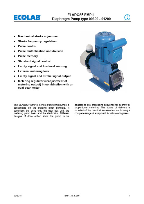
∙ Mechanical stroke adjustment ∙ Stroke frequency regulation ∙ Pulse control∙ Pulse multiplication and division ∙ Pulse memory∙ Standard signal control∙ Empty signal and low level warning ∙ External metering lock∙ Empty signal and stroke signal output ∙ Metering regulator (readjustment ofmetering output) in combination with an oval gear meterThe ELADOS ® EMP III series of metering pumps is constructed on the building block principle. It comprises the drive unit, the gear box unit, the metering pump head and the electronics. Different designs of drive option allow the pump to beadapted to any processing sequence for quantity or proportional metering. The scope of delivery is rounded off by practical accessories, so forming a complete range of equipment for all metering uses.Technical Data:Mechanical Data:Pump capacity [l/h]: 80 120Metering back-pressure[bar]: 4 3Delivery capacityper stroke [cm3]: 10.8 16.1 Reproductivity: <± 3 %Suction height: 2 mWs, suction heightwith clean, slightly wetvalvesMetering frequency max.: 122 1/minPressure valve: without spring Suction valve: without spring Ambient temperature max.: 40° C Electrical Data:Connection: 230 V / 50/60 HzAt a mains frequency of60 Hz, delivery capacityincreases by 20 %,whereas metering back-pressure decreases by20 %.Special voltages onrequestCurrent consumption[mA]: 950 (50 Hz)Power output [W]: 90 (50 Hz)Safety type: IP 55InsuIation class: FMaterial:Housing: thermoplastic polyesterPump head: polypropyleneoptional PVDF, PVC orstainless steel 1.4571 Diaphragm: PTFE – EPDM compound diaphragm Seals: FPM 602 (Viton B)optional EPDM or KalrezValve balls: ceramicsoptional PTFE orstainless steel 1.4401Weight [kg]: 8.6 8.8Colour: blue RAL 5007Special versions on requesDimensions:Version E 00Capacity Dimensions [mm]l/h A C L H1 H2 D80 74.5 ∅ 130 328 219.3 175.5 1 ¼“120 74.5 ∅ 140 330 224.3 185.5 1 ¼“Dimensions:Version E 10 – E 60Capacity Dimensions [mm]l / h A B C L H1 H2 D80 74.5 140 ∅ 130 328 219.3 175.5 1 1/4"120 74.5 145 ∅ 140 330 224.3 185.5 1 1/4"Pump code – part 11. Electrical version (please see legend on page 7)E 00E 10Pump code – part 211. Connection suction sideExample of a complete pump code of a standard pump:E6001200PP03FP KE PP990108- 0707PP999901 (Pump code 1) (Pump code 2)Electrical versionsE 00 Mechanical stroke adjustmentE 10 On / off switch, mechanical stroke adjustmentE 60 • Mechanical stroke adjustment• Back-lit graphic display, 4 operating keys• Single stroke control (each stroke is completely executed)• Metering monitoring via stroke-signal output or via external metering-monitoring system(e.g. liquid level switch) possible• Registration of operating and consumption data (calculative)• Calibration functionSelectable operating modes:Internal modeSelection of metering rate/metering frequency via:• Strokes/min• Percent• Liter/h (or gallon/h)External mode• Pulse mode (actuation via pulses)- Pulse multiplication (one incoming pulse = n metering strokes)- Pulse division (n incoming pulses = 1 metering stroke)• Standard signal mode (actuation via external standard signal 0/4-20 mA or 20-0/4 mA)• Charge mode (a previously selected quantity is metered, with initiation via an external initiation pulse)Inputs:• Level monitoring, package vessel (reserve and empty signal)• Pulse• Standard signal• Enable (metering interlock)• Metering controlOutputs:• Level monitoring package vessel / malfunction• Stroke signalOrdering data – standard pumps:Article Pump code Material-No. ELADOS® EMP III E00 00800 PP 04 FP KE PP 99 99 08 – 07 07 PP 99 99 01 149301 E00 01200 PP 03 FP KE PP 99 99 08 – 07 07 PP 99 99 01 149401Extent of supply:hose connection material 12/21 mm,operating instructions, without connectioncableELADOS® EMP III E10 00800 PP 04 FP KE PP 99 01 08 – 07 07 PP 99 99 01 149310 E10 01200 PP 03 FP KE PP 99 01 08 – 07 07 PP 99 99 01 149410Extent of supply: 2.0 m connection cable with shock-proof plug,hose connection material 12/21 mm,operating instructionsELADOS® EMP III E60 00800 PP 04 FP KE PP 99 01 08 – 07 07 PP 99 99 01 149860 E60 01200 PP 03 FP KE PP 99 01 08 – 07 07 PP 99 99 01 149960Extent of supply: 2.0 m connection cable with shock-proof plug,hose connection material 12/21 mm, dummyplug for empty signal input, dummy cap forempty signal or stroke signal output, 5-pinconnection plug for pulse or standard signalinput, plug allocation plan, operatinginstructionsELADOS® EMP III E 60PLUSwith the add-on unit (Dongle Box) for connection of an OGM PLUS oval gear meter the version E 60turns to version E 60PLUSArticle Material-No.248606Dongle Box∙ Automatic readjustment of pump output in combinationwith an oval gear meter (for operating modes "internal"and "current" only)∙ Automatic calibration function via oval gear meter∙ Consumption data control by means of oval gear meterAccessories:for volumetric measurement of the rate of flowOrdering data are to be found in chapter 6 of “Measuring andControlling”.Accessories (suction side)Accessories:ArticleMaterialNo.Suction lances D32 with reserve and empty signal reportincl. of ball non-return valve, suction strainer, zero-potential empty signal contact (empty = contact interrupted)Tube diameter: 32 mm Hose connection: 12/21 mm Connection cable: circular connector Turn-on voltage: max.50 V AC/DC Switching current: 0.5 ARupturing capacity: 10 W / 10 VASGL VCPVFPEPGL000 G5/8-10-2SS-0475-99-07 (for container 20 l) SGL VCPVFPEPGL000 G5/8-10-2SS-0725-99-07 (for container 30/60 l)SGL VCPVFPEPGL000 G5/8-10-2SS-0975-99-07 (for container 100/200 l) SGL VCPVFPEPGL000 G5/8-10-2SS-1125-99-07 (for container 200 l) 186157186158186159186160Please see next page for pump code declaration.12525Suction lance code* standard valve ball material will soon be changed to ceramicsArticleMaterial No.Adapter – insert capfor suction lance Ø 32 mm PVC softto attach on: canister 10 l and 20 l286198Adapter – screw jointfor suction lance Ø 32 mm PVC hard Thread pitch: 5 mm Threaded int. diameter: 56 mm Threaded ext. diameter: 61 mm can be screwed on: canister 30 l or container 60 –200 l 286197Suction lance adapter, rigid PVC/Viton Bfor canister and barrel288549Suction lance adapter, rigid PVC/Viton Bfor barrels (l-ring plus – barrel 220)288547Suction lance adapter, rigid PVC/Viton Bfor container (ECOBULK-container with skid pallet) for screw in in screw cap with 2” Tri-Sure-Stuffing288548Article Material No.Adapter – insert capfor suction lance Ø 32 mmPVC – hard / Viton Bappropriate for degassing productsReturn connection: 4/6, 6/8 or 6/12 mm (int.Ø/ext.Ø)Vent connection: 6/12 mm (int.Ø/ext.Ø)to attach on: canister 30 l orcontainer 60 – 200 l288534Adapter – screw jointfor suction lance Ø 32 mmPVC – hard / Viton B / siliconeappropriate for degassing productsReturn connection: 4/6, 6/8 or 6/12 mm (int.Ø/ext.Ø)Vent connection: 6/12 mm (int.Ø/ext.Ø)Thread pitch: 5 mmThreaded int. diameter: 63 mmThreaded ext. diameter: 69 mmfor barrel with internal thread (L–ring plus barrel 220 l)288535Terminal box for connection cable of the suction pipefor connection cable with round plugincl. cable union PG 7 (max. 2 x 1 m²)288419Protection tubes for suction lances, D32for prevention of mechanical damage of the suction valveand the float respectively;suitable for all suction lances Ø 32 mmProtection tube, PVDF, 32.5/40 (int.Ø/ext.Ø)incl. fastening screw286191 Protection tube, VA (1.4035), 32.5/40 (int.Ø/ext.Ø)incl. fastening screw286153Bottom admission valve1. Valve designationArticleMaterial-No.BSV VC PV FP GL 000 G 1¼ – 07 249019 BSV VC PV EP GL 000 G 1¼ – 07 249025 BSV VA VA FP VA 000 G 1¼ – 99 249036 BSV VA VA EP VA 000 G 1¼ – 99on requestHose connection: bush for hose NW 16 mm and NW 19 mm BSV VC PV FP GL 000 G 1¼ – XX 249017 BSV VC PV EP GL 000 G 1¼ – XX249030* standard valve ball material will soon be changed to ceramicsArticleMaterial No.Multiple function valveThis safety-relevant component serves thepurpose of protecting the piping system and the metering pump and permits safe and reliable commissioning and maintenance of the system. The multiple function valve combines all of the following functions: overflow, pressure maintenance, venting and drainage.on requestArticle Material No.Pulsation damperTo reduce pressure peaks and pulsation at oscillatingrotary pumps at the pressure side and to preventcavitating at the suction side.Stroke volume: 40 cm³/strokeAdmissible nominal pressure: 10 barThread connection: G 1 ¼PDS 250 D25 PP/HypalonHousing material: PPSealing/diaphragms: Hypalon415503005PDS 250 D25 PP/VitonHousing material: PPSealing/diaphragms: Viton415503006Manometer0-10 bar, connection G ¼Attention:When adjusting the initial pressure the pulsationdamper has to be relieved on the metering mediaside.415502560 Reduction G ½ a – G ¼ a415202771Pressure maintenance valveHousing material: PVCDiaphragm: EPDM/PTFESeals: Viton BConnections: adhesive muffs 25Response pressure: 0.2-10 bar (adjustable)415708711Article Article no.Metering valve with metering pipeDVP PFC-008-G3/4-G11/4-150-99 252184 DVP PEC-008-G3/4-G11/4-150-99 252185DVP DFC-008-G3/4-G11/4-150-99 252186 DVP DEC-008-G3/4-G11/4-150-99 252187Note: Please order connection material for hose and pipe connection separately. Connection sets see pageArticle Article no.Metering valve without metering pipe (suction / pressure valve)SDV PFC-008-G11/4-G11/4-99 249518 SDV PEC-008-G11/4-G11/4-99 249519SDV DFC-008-G11/4-G11/4-99 252038 SDV DEC-008-G11/4-G11/4-99 252039Note: Please order connection material for hose and pipe connection separately. Connection sets see page 19.Connection materialArticle Article no. Connection set for PVC hose 12/21 mmConnection set Di12/Da21-G11/4-PP-GY Connection set Di12/Da21-G11/4-PVDF-NA 249238 249258Connection set for PEX pipe 12/16 mmScrew-on connection PVDF, G1¼“i - PEX 12/16 Screw-on connection PP, G1¼“i - PEX 12/16 250076 250099Connecting parts for pipe connection DN20/d25Union nut PVDF G1¼“Insertion part (welded sleeve) PVDF DN20/d25 - 1¼“ 415099072 415099033Union nut PP G1¼“Insertion part (welded sleeve) PP DN20/d25 - 1¼“ 415099835 415099709Connecting parts for transition to standard threadUnion nut PVDF G1¼“Insertion part PVDF G1/2“i - 1¼“ Insertion part PVDF G1“a (NPT) - 1¼“ 415099072 34950235 34900277Union nut PP G1¼“Insertion part PP G1/2“i - 1¼“ Insertion part PP G1“a (NPT) - 1¼“ 415099835 34950259 34900276Accessories (general)Article Material No.Suction and pressure linesavailable by the metremax. operating pressure: 15 bar (at 20° C)PVC-fabric, 12/21 mm (int.Ø/ext.Ø) 417400127PVC-fabric, 19/27 mm (int.Ø/ext.Ø) 417400131 Note: We explicitly point out that PVC fabric tubes have alimited lifetime if alkaline chemicals will be used. To avoiddamage for your staff and your company the tubes haveto be exchanged at least every 6 months. In case of non-compliance we exclude all kinds of liability andresponsibility.PE-X tube 12/16 mm 417400362Accessories (general)Article Material No.Signal horn with integrated red flash light230 V / 50 Hz / IP 33 RO418271053Wall bracketmade of stainless steel 1.4301incl. of attachment parts (dowels and screws) 286013Connection cable, 5 m lengthfor empty signal input with straight 4-pin plug 418439001 for pulse or current input with straight 5-pin plug 418439007 for empty signal or stroke signal outputwith straight 4-pin plug 418439022Spare parts:Spare parts:Item.-No. Article Material No.1 Suction/pressure valve, SDV PP FP KE 000 G1¼ - G1¼ - 99*Suction/pressure valve, SDV PP EP KE 000 G1¼ - G1¼ - 99*Suction/pressure valve, SDV PV FP KE 000 G1¼ - G1¼ - 99*Suction/pressure valve, SDV PV EP KE 000 G1¼ - G1¼ - 99* 249075 249055 249074 2490412 Connection set PP G1¼ - 12/21 mmConnection set PVDF G1¼ - 12/21 mm(consisting of union nut, clamping piece and tapered part) 249238 2492589 Screw 41303104211 Covering stopper 3490016812 Transparent enclosure cover 34800120 13a Dummy plug empty signal input 248186 13b Cover cap control output 34800117 13c Dummy plug control input 248187 14a 4-pin plug, empty signal input 418463115 14b 4-pin plug, control output 418463117 14c 5-pin plug, control input 41846311815 Screw B40x16 41307116716 Mounting plate 34900120Pos. Article 80 l/h 120 l/h3 Pump head screw 413031047 4130310644 Pressing plate 34900139 349001405 Pump head PP34900105 349001064Pump head PVDF34900178 349001796 Diaphragm 34900111 349001127 Supporting disk 34900149 349001518 Intermediate ring 34900136 34900137 10 Intermediate plate 34900134 34900135* Please see next page for code declaration.Suction and pressure valve code1. Valve designationWearing PartsSet of wearing parts (complete)consisting of 1 piece each:∙Suction valve with hose connection material∙Pressure valve with hose connection material∙Diaphragm∙Supporting ringArticle Code Material-No.Wearing part set EMP III 00800 PP FP KE 249560EMP III 01200 PP FP KE 249561EMP III 00800 PP EP KE 249562EMP III 01200 PP EP KE 249563EMP III 00800 PV FP KE 249564EMP III 01200 PV FP KE 249565EMP III 00800 PV EP KE 249566EMP III 01200 PV EP KE 249567。
气动隔膜泵说明书

■产品概述QBY3第三代气动隔膜泵具有简单、高可靠设计的空气换向阀,使整个QBY3系列产品能在各种应用情况下实现最大的稳定性。
换向阀为三向先导阀,能保证真正意义上的不“发粘”。
所有部件在不打开液体腔的情况下进行更换。
铝质部件经阳极氧化处理并附环氧涂层,能抵御不洁空气造成的腐蚀。
■优势所在●可在不良气源的情况下使用,换向阀中Derlin材质的滑块坚固耐用,不易损坏;●气路畅通,从1/2‘到3’泵的气路部分绝无障碍,保证换向灵活;●100%可外部维护式换向阀;●与其它的双隔膜泵相比,活动部件非常少;●先导式换向阀具有极高的机械寿命,可保障日复一日的运行;●一种换向阀适合多种规格的泵。
■与众不同A维护便利降低内部容积可减少浪费,便于清洗;不锈钢螺栓可抗腐蚀,并能提供合理的定位,便于重新装配。
B独特的空气阀采用先导式空气阀,完全消除停机现象,所有零件的更换都不需要打开内腔,空气管道无润滑要求。
C精密配合的零件耐磨的端轴承可确保阀杆的正确定位,更换简单。
D给予保护的排放口所有排放口采用一个公共端可防止室内的汽化液体侵蚀空气马达的密封件,便于贮槽加载或者卸载操作的空转功能E外部结构坚固整个结构防腐蚀、防渗漏,换色清洗方便。
经特殊工艺处理的浸渍部件和空气腔,可承受恶劣工作环境。
F流体的相容性可提供外壳材料包括:不锈钢、铸钢、聚丙烯、铝合金等。
G合理的密封设计隔膜可紧紧锁定在位,可起到积极液封作用的成形压条。
H重型隔膜板夹持可靠的隔膜板能消除一切渗漏和脱落现象,避免发生昂贵的停工费用。
I长效的阀杆设计不锈钢的阀杆具有更长的使用寿命在潮湿空气中仍具有良好的抗腐蚀功能。
J便于定位螺栓连接的,自定位的空气和流体单位K弹性材料的选择各类阀座和阀球选项可确保流体的相容性和可靠的密封从而具有极高的效率,长效的使用寿命和更佳的吸升高度。
■过流部件■隔膜材料■阀球■阀座■型号意义■QBY3-15铝合金/不锈钢/铸钢■零部件明细表序号名称序号名称序号名称序号名称01 出料口(上盖)02 堵头03 球阀04 球座05 气阀室垫片06 助动杆07 滑块08 活塞V型圈09 活塞10 引导块11 气阀室垫片12 引导块垫片13 气阀室14 气阀盖15 助动杆O型圈16 连杆轴套17 消声器18 气阀室座19 立柱20 夹板螺丝21 外夹板22 四氟膜片23 内夹板24 O型圈25 连杆轴V型圈26 连杆轴27 进料口(下盖)■规格参数规格型号QBY3-10 QBY3-15 最大工作流量18.9升/分钟18.9升/分钟最大工作压力0.7Mpa 0.7Mpa流体出口尺寸10mm 15mm流体进口尺寸10mm 15mm空气进口尺寸1/4 in.npt(f) 1/4 in.npt(f) 最大虹吸高度(干抽) 2.5-3m 2.5-3m 最大输送固体颗粒 1.5mm 1.5mm最大空气消耗量9.0 scfm 9.0 scfm 每行程流量0.006 gallon(23cc) 0.006 gallon(23cc)每往复流量0.012 gallon(46cc) 0.012 gallon(46cc)最大往复速度(干运转)320 cpm 320 cpm (湿运转)250 cpm 250 cpm泵主体结构材质铸钢、铝合金、PP、不锈钢、PTFE■安装尺寸■QBY3-20 QBY3-25 塑料PP聚丙烯、氟塑料■零部件明细表序号名称序号名称序号名称序号名称01 进气嘴02 气阀盖03 气阀盖密封圈04 引导块05 引导块垫片06 进料口(上盖)07 隔排08 内夹板垫片09 内夹板10 聚胶膜片11 四氟膜片12 外夹板13 夹板螺丝14 滑块15 助动杆16 立柱17 球座O型圈18 球座套19 球阀20 球座挡片21 球座O型圈22 堵头23 助动杆O型圈24 活塞V型圈25 滑块26 气阀室27 气阀室座垫片28 气阀室座29 消声器30 活塞31 气阀室垫片32 进料口(下盖)33 连杆轴V型圈■规格参数型号规格QBY3-20 QBY3-25最大工作流量57升/分钟57升/分钟最大工作压力0.7Mpa 0.7Mpa流体出口尺寸20mm 25mm流体进口尺寸20mm 25mm空气进口尺寸1/4 in.npt(f) 1/4 in.npt(f) 最大虹吸高度(干抽) 4.5m 4.5m最大虹吸高度(湿抽)7.6m 7.6m最大输送固体颗粒 2.5mm 2.5mm最大空气消耗量28scfm 28 scfm每往复流量0.04gallon(0.15lpm) 0.04gallon(0.15lpm)最大往复速度400 cpm 400 cpm泵主体结构材质铸钢、铝合金、PP、不锈钢、PTFE ■安装尺寸■QBY3-20 QBY3-25铝合金■零部件明细表序号名称序号名称序号名称序号名称01 进气嘴02 气阀盖03 气阀盖垫片04 滑块05 助动杆O型圈06 活塞V型圈07 引导块08 引导块垫片09 隔排10 助动杆11 活塞12 堵头13 进料口(上盖)14 球阀15 球座16 连杆轴17 气阀室垫片18 连杆轴V型圈19 气阀室20 气阀室座垫片21 气阀室座22 消声器23 立柱24 夹板螺丝25 夹板O型圈26 外夹板27 四氟膜片28 聚胶膜片29 内夹板30 内夹板垫片31 出料口(下盖)■规格参数型号规格QBY3-20 QBY3-25 最大工作流量57升/分钟57升/分钟最大工作压力0.7Mpa 0.7Mpa流体出口尺寸20mm 25mm流体进口尺寸20mm 25mm空气进口尺寸1/4 in.npt(f) 1/4 in.npt(f) 最大虹吸高度(干抽) 4.5m 4.5m最大虹吸高度(湿抽)7.6m 7.6m 最大输送固体颗粒 2.5mm 2.5mm最大空气消耗量28scfm 28 scfm每往复流量0.04gallon(0.15lpm) 0.04gallon(0.15lpm)最大往复速度400 cpm 400 cpm泵主体结构材质铸钢、铝合金、PP、不锈钢、PTFE■安装尺寸■QBY3-20 QBY3-25不锈钢/铸钢■零部件明细表序号名称序号名称序号名称序号名称01 进气嘴02 气阀盖03 垫片04 助动杆O型圈05 滑块06 助动杆07 活塞V型圈08 引导块09 引导块垫片10 气阀室11 隔排12 滑块13 活塞14 堵头15 出料口(上盖)16 球阀17 球座18 连杆轴19 气阀室座垫片20 气阀室座21 消声器22 连杆轴V型圈23 堵头24 立柱25 夹板螺丝26 外夹O型圈27 外夹板28 四氟膜片29 聚胶膜片30 内夹板31 内夹板垫片32 气阀室垫片33 进料口(下盖)■规格参数型号规格QBY3-20 QBY3-25最大工作流量57升/分钟57升/分钟最大工作压力0.7Mpa 0.7Mpa流体出口尺寸20mm 25mm流体进口尺寸20mm 25mm空气进口尺寸1/4 in.npt(f) 1/4 in.npt(f) 最大虹吸高度(干抽) 4.5m 4.5m最大虹吸高度(湿抽)7.6m 7.6m最大输送固体颗粒 2.5mm 2.5mm最大空气消耗量28scfm 28 scfm每往复流量0.04gallon(0.15lpm) 0.04gallon(0.15lpm)最大往复速度400 cpm 400 cpm泵主体结构材质铸钢、铝合金、PP、不锈钢、PTFE■安装尺寸■QBY3-25A铝合金■零部件明细表序号名称序号名称序号名称序号名称01 气阀盖垫片02 大滑块铝件03 活塞04 V型圈05 助动杆O型圈06 助动杆套07 大滑块垫08 引导块09 引导块垫片10 出料口(上盖)11 球阀12 球座13 气阀盖14 助动杆15 小滑块16 小滑块O型圈17 连杆轴18 活塞套19 气阀室20 消声器21 进料口(下盖)22 立柱23 夹板螺丝24 夹板O型圈25 外夹板26 四氟膜片27 聚胶膜片28 内夹板29 隔排30 气阀室垫片31 连杆轴套32 V型圈■规格参数型号规格QBY3-25AL最大工作流量116升/分钟最大工作压力0.84Mpa流体出口尺寸40mm流体进口尺寸40mm空气进口尺寸1/2in.npt(f) 最大虹吸高度(干抽或湿抽) 5.48m最大输送固体颗粒 3.2mm最大空气消耗量60scfm每往复流量0.15gallon(0.57lpm)最大往复速度276 cpm泵主体结构材质铸钢、铝合金、PP、不锈钢、PTFE■安装尺寸■QBY3-25A不锈钢/铸钢■零部件明细表序号名称序号名称序号名称序号名称01 活塞02 活塞V型圈03 助动杆04 助动杆O型圈05 助动杆套06 引导块07 引导块垫片08 气阀室09 消声器10 进料口(上盖)11 气阀盖12 气阀盖垫片13 大滑块铝件14 小滑块15 大滑块O型圈16 大滑块座17 连杆轴18 活塞套19 球阀20 球座21 出料口(下盖)22 立柱23 夹板螺丝24 夹板O型圈25 外夹板26 四氟膜片27 聚胶膜片28 内夹板29 隔排30 气阀室垫片31 连杆轴套32 V型圈■规格参数型号规格QBY3-25AP最大工作流量116升/分钟最大工作压力0.84Mpa流体出口尺寸40mm流体进口尺寸40mm空气进口尺寸1/2in.npt(f) 最大虹吸高度(干抽或湿抽) 5.48m最大输送固体颗粒 3.2mm最大空气消耗量60scfm每往复流量0.15gallon(0.57lpm)最大往复速度276 cpm泵主体结构材质铸钢、铝合金、PP、不锈钢、PTFE■安装尺寸■QBY3-32 QBY3-40 塑料PP聚丙烯、氟塑料■零部件明细表序号名称序号名称序号名称序号名称01 堵头02 出料口(上盖)03 气阀盖垫片04 大滑块铝件05 活塞06 V型圈07 小滑块08 助动杆09 助动杆O型圈10 助动杆套11 引导块12 引导块垫片13 气阀室14 堵头15 球阀16 球座17 气阀室盖18 大滑块O型圈19 大滑块座20 立柱21 连杆轴22 连杆轴套23 V型圈24 活塞套25 夹板螺丝26 外夹O型圈27 外夹板28 四氟膜片29 聚胶膜片30 内夹板31 隔排32 气阀室垫片33 消声器34 进料口(下盖)■规格参数型号规格QBY3-32 QBY3-40 最大工作流量151升/分钟151升/分钟最大工作压力0.84Mpa 0.84Mpa流体出口尺寸32mm 40mm流体进口尺寸32mm 40mm空气进口尺寸1/2in.npt(f) 1/2in.npt(f) 最大虹吸高度(干抽或湿抽) 5.48m 5.48m 最大输送固体颗粒 3.2mm 3.2mm最大空气消耗量60scfm 60scfm 每往复流量0.15gallon(0.57lpm) 0.15gallon(0.57lpm)最大往复速度276 cpm 276 cpm泵主体结构材质铸钢、铝合金、PP、不锈钢、PTFE■安装尺寸■QBY3-32 QBY3-40铝合金■零部件明细表序号名称序号名称序号名称序号名称01 出料口(上盖)02 堵头03 气阀盖垫片04 大滑块铝件05 活塞06 V型圈07 小滑块08 助动杆O型圈09 助动杆套10 引导块11 引导块垫片12 气阀室13 堵头14 球阀15 球座16 气阀室盖17 助动杆18 大滑块O型圈19 大滑块座20 立柱21 连杆轴22 连杆轴套23 V型圈24 活塞套25 夹板螺丝26 夹板O型圈27 外夹板28 四氟膜片29 聚胶膜片30 内夹板31 隔排32 气阀室垫片33 消声器34 进料口(下盖)■规格参数型号规格QBY3-32 QBY3-40 最大工作流量151升/分钟151升/分钟最大工作压力0.84Mpa 0.84Mpa流体出口尺寸32mm 40mm流体进口尺寸32mm 40mm空气进口尺寸1/2in.npt(f) 1/2in.npt(f) 最大虹吸高度(干抽或湿抽) 5.48m 5.48m 最大输送固体颗粒 3.2mm 3.2mm最大空气消耗量60scfm 60scfm 每往复流量0.15gallon(0.57lpm) 0.15gallon(0.57lpm)最大往复速度276 cpm 276 cpm泵主体结构材质铸钢、铝合金、PP、不锈钢、PTFE■安装尺寸■QBY3-32 QBY3-40不锈钢/铸钢■零部件明细表序号名称序号名称序号名称序号名称01 出料口(上盖)02 堵头03 气阀盖垫片04 大滑块铝件05 活塞06 V型圈07 小滑块08 助动杆09 助动杆O型圈10 助动杆套11 引导块12 引导块垫片13 球阀14 球阀15 气阀室盖16 大滑块O型圈17 大滑块座18 立柱19 连杆轴20 连杆轴套21 活塞套22 V型圈23 夹板螺丝24 夹板O型圈25 外夹板26 四氟膜片27 聚胶膜片28 内夹板29 隔排30 气阀室垫片31 消声器32 进料口(下盖)33 气阀室■规格参数型号规格QBY3-32 QBY3-40 最大工作流量151升/分钟151升/分钟最大工作压力0.84Mpa 0.84Mpa流体出口尺寸32mm 40mm流体进口尺寸32mm 40mm空气进口尺寸1/2in.npt(f) 1/2in.npt(f) 最大虹吸高度(干抽或湿抽) 5.48m 5.48m 最大输送固体颗粒 3.2mm 3.2mm最大空气消耗量60scfm 60scfm 每往复流量0.15gallon(0.57lpm) 0.15gallon(0.57lpm)最大往复速度276 cpm 276 cpm泵主体结构材质铸钢、铝合金、PP、不锈钢、PTFE■安装尺寸■QBY3-50 QBY3-60塑料PP聚丙烯、氟塑料■零部件明细表序号名称序号名称序号名称序号名称01 出料口(上盖)02 球阀03 球座04 气阀盖垫片05 大滑块铝件06 活塞07 V型圈08 小滑块09 大滑块O型圈10 引导块11 引导块垫片12 引导块垫片13 气阀室盖14 助动杆15 助动杆O型圈16 助动杆套17 立柱18 外夹板19 四氟膜片20 聚胶膜片21 内夹板22 隔排23 连杆轴套24 V型圈25 进料口(下盖)26 气阀室27 消声器28 气阀室垫片29 活塞套30 连杆轴31 32■规格参数型号规格QBY3-50 QBY3-65 最大工作流量378.5升/分钟378.5升/分钟最大工作压力0.84Mpa 0.84Mpa流体出口尺寸50mm 65mm流体进口尺寸50mm 65mm空气进口尺寸1/2in.npt(f) 1/2in.npt(f)最大虹吸高度(干抽或湿抽) 5.48m 5.48m 最大输送固体颗粒 5.48mm 5.48mm最大空气消耗量125scfm 125scfm 每往复流量0.5gallon(1.96lpm) 0.5gallon(1.96lpm)最大往复速度276 cpm 276 cpm泵主体结构材质铸钢、铝合金、PP、不锈钢、PTFE■安装尺寸■QBY3-50 QBY3-65铝合金■零部件明细表序号名称序号名称序号名称序号名称01 出料口(上盖)02 堵头03 气阀盖垫片04 大滑块铝件05 活塞06 V型圈07 小滑块08 助动杆O型圈09 助动杆套10 引导块11 引导块垫片12 气阀室13 堵头14 球阀15 球座16 气阀室盖17 助动杆18 大滑块O型圈19 大滑块座20 立柱21 连杆轴22 连杆轴套23 V型圈24 活塞套25 夹板螺丝26 夹板O型圈27 外夹板28 四氟膜片29 聚胶膜片30 内夹板31 隔排32 气阀室垫片33 消声器34 进料口(下盖)■规格参数型号规格QBY3-50 QBY3-65最大工作流量378.5升/分钟378.5升/分钟最大工作压力0.84Mpa 0.84Mpa流体出口尺寸50mm 65mm流体进口尺寸50mm 65mm空气进口尺寸1/2in.npt(f) 1/2in.npt(f) 最大虹吸高度(干抽或湿抽) 5.48m 5.48m 最大输送固体颗粒 5.48mm 5.48mm最大空气消耗量125scfm 125scfm每往复流量0.5gallon(1.96lpm) 0.5gallon(1.96lpm)最大往复速度276 cpm 276 cpm泵主体结构材质铸钢、铝合金、PP、不锈钢、PTFE■安装尺寸。
环型防喷器说明书
5. 结构特点 ............................................................................................................................... 12
5.1. 结构简单可靠 ................................................................................................................ 12 5.2. 耐磨圈结构.................................................................................................................... 12 5.3. 唇形密封圈结构 ............................................................................................................ 12 5.4. 抗硫化氢性能 ................................................................................................................ 12 5.5. 活塞 ............................................................................................................................... 13 5.6. 球形胶芯........................................................................................................................ 13 6. 安装与使用 ........................................................................................................................... 14
RF3操作手册

操作手册AutoFilt® RF3贺德克液压技术(上海)有限公司上海市闵行经济技术开发区绿春路271号, 200245电话:0086 21 6463 3510传真:0086 21 6430 0257邮箱:hydacsh@网址:索引1. 安全1.1基本的安全注释1.2符号及注释声明1.3合乎规定的应用1.4反冲洗过滤器AutoFilt RF3操作中的潜在危险1.5操作者及维护人员的职责1.6紧急情况下采取的措施1.7维护、保养及故障排除1.8电气事故1.9防燃保护措施1.10反冲洗过滤器的结构变更2.运输和存储2.1运输2.2存储3.反冲洗过滤器的技术说明3.1功能说明3.2反冲洗过滤器的可调节工作参数3.3反冲洗过滤器的结构4.主要元件说明4.1滤芯4.2齿轮马达4.2.1气动马达4.3反冲洗阀4.3.1反冲洗阀的驱动装置(适用于EPT&PT)4.3.1.1反冲阀的排气量控制(适用于EPT&PT)4.3.1.2反冲洗阀的控制阀(适用于EPT)4.3.2反冲洗阀的驱动装置(适用于EU)4.4压差表4.5位置开关4.5.1感应接近开关(适用于EPT&EU)4.5.2回转滑阀(适用于PT&PTZ)4.6压缩空气供给(适用于PT&PTZ)4.6.1压缩空气的调节阀和过滤器(适用于PT&PTZ)4.6.2压缩空气-润滑器(适用于PT&PTZ)5.控制装置5.1电气和电动控制 – EPT和EU5.2气动循环控制 - PT&PTZ6.安装6.1管口方位的调整6.2反冲洗过滤器法兰方位的重新定位6.2.1旋转进出口法兰6.2.2旋转反冲洗管路6.3安装6.3.1安装反冲洗管路6.4接通电源 – EPT和EU6.5连接压缩空气供应 – EPT、PT和PTZ7.反冲洗过滤器的使用7.1操作和监控元件7.2反冲洗过滤器的试运行7.2.1设置工作参数7.3停止运转反冲洗过滤器7.4适用较长时间停机的过滤器停止运转8.反冲洗过滤器的维护8.1操作人员进行的检查工作8.2维护工作8.3故障原因及排除8.3.1带气动控制或电动循环控制的反冲洗过滤器的故障原因 – EPT和EU8.3.2带气动控制的反冲洗过滤器的故障原因 - PT&PTZ8.4滤芯的取出和装入8.4.1取出滤芯8.4.2装入滤芯9.AUTOFILT RF3的型号代号10.技术参数11.备件12.EC认证图1:反冲洗过滤器的功能原理图2:反冲洗过滤器的结构图3:带接线示意图的压差表图4:反冲洗过滤器的面板图5:反冲洗过滤器的配电盘图6:装配反冲洗过滤器规格C 至 2图7:装配反冲洗过滤器规格2.5 至 8图8:进出口法兰的重新定位图9:反冲洗过滤器的电器回路图图10:压缩空气供应的连接——EPT图11:取出和装入滤芯图12: RF3备件图13: RF3密封件表格索引表1:反冲洗过滤器的运输重量表2:元件的能源供应表3:齿轮马达的维护和保养工作表4:齿轮马达的润滑剂选择表表5:齿轮马达固定螺栓的扭矩表6:带电动马达的齿轮马达的技术参数(EPT和EU)表7:带气动马达的驱动装置的技术参数 - PT表8:压差表的技术参数表9:反冲洗过滤器RF3的安装尺寸表10:反冲洗过滤器壳体的重量表11:控制装置的操作元件表12:检查工作计划表13:维护计划表14:带电气、电动同步控制或电动循环控制的反冲洗过滤器的故障排除表15:带气动控制的反冲洗过滤器的故障排除表16:带齿轮马达的反冲洗过滤器盖板的重量表17:盖板和壳体螺栓的扭矩表18:反冲洗过滤器的技术数据表19:带EPT或EU控制的反冲洗过滤器的连接电压表20:备件表同时提供的资料索引随操作手册还提供下列资料:1. 电动回路图或气动回路图1.1基本的安全注释安全操作反冲洗过滤器及其无故障运行的前提条件是了解和注意基本的安全注释及安全规定。
贝利莫三孔钢球阀数据表说明书

B347•ApplicationStainless Steel Ball and StemTechnical dataFunctional dataValve Size 2" [50]Fluidchilled or hot water, up to 60% glycol Fluid Temp Range (water)0...250°F [-18...120°C]Body Pressure Rating 400 psi Close-off pressure ∆ps 200 psiFlow characteristic A-port equal percentage, B-port modified for constant common port flow Servicing maintenance-free Flow Pattern 3-way Mixing/Diverting Leakage rate0% for A – AB, <2.0% for B – AB Controllable flow range 75°Cv29 Body pressure rating note 400 psiCv Flow RatingA-port: as stated in chart B-port: 70% of A – AB Cv MaterialsValve body Nickel-plated brass body Stem seal EPDM (lubricated)SeatPTFEPipe connection NPT female ends O-ring EPDM (lubricated)Ballstainless steel Suitable actuatorsNon-SpringARB(X)Safety notesWARNING: This product can expose you to lead which is known to the State of California to cause cancer and reproductive harm. For more information go to Product featuresThis valve is typically used in air handling units on heating or cooling coils, and fan coil unit heating or cooling coils. Some other common applications include Unit Ventilators, VAV box re-heat coils and bypass loops. This valve is suitable for use in a hydronic system with variable or constant flow.B347 Flow/Mounting detailsDimensionsDimensional drawingsARB, ARXA B C D E F H110.5" [267] 4.9" [125]7.7" [196] 6.0" [152] 1.7" [44] 2.6" [66]0.8" [20]ARB N4, ARX N4A B C D E F11.4" [289] 4.9" [125]9.8" [249]8.0" [203] 3.1" [80] 3.1" [80]ARQB, ARQXA B C D E F H1H29.9" [251] 4.9" [125]8.3" [211] 6.6" [168] 2.3" [58] 2.6" [66]0.8" [20]0.6" [15]AFRB, AFRXA B C D E F11.3" [286] 4.9" [125]8.3" [211] 6.6" [168] 2.6" [66] 2.6" [66]AFRB N4, AFRX N4A B C D E F13.0" [330] 4.9" [125]11.8" [300]9.9" [251] 3.7" [95] 3.7" [95]A B C D E F11.3" [286] 4.9" [125]8.3" [211] 6.6" [168] 2.6" [66] 2.6" [66]ARQB, ARQXA B C D E F H1H29.9" [251] 4.9" [125]8.3" [211] 6.6" [168] 2.3" [58] 2.6" [66]0.8" [20]0.6" [15]AFRB N4, AFRX N4A B C D E F13.0" [330] 4.9" [125]11.8" [300]9.9" [251] 3.7" [95] 3.7" [95]ARB24-3•••••On/Off, Floating Point, Non-Spring Return, 24 VTechnical dataElectrical dataNominal voltageAC/DC 24 V Nominal voltage frequency 50/60 Hz Power consumption in operation 2.5 W Power consumption in rest position 0.5 WTransformer sizing 5.5 VA (class 2 power source)Electrical Connection 18 GA plenum cable, 3 ft [1 m], with 1/2" conduit connectorOverload Protectionelectronic thoughout 0...90° rotation Functional dataInput Impedance 600 ΩDirection of motion motor selectable with switch 0/1Manual override external push button Angle of rotation 90°Angle of rotation note adjustable with mechanical stop Running Time (Motor)90 s Noise level, motor 45 dB(A)Position indicationMechanically, pluggable Safety dataDegree of protection IEC/EN IP54Degree of protection NEMA/UL NEMA 2 UL Enclosure Type 2Agency Listing cULus acc. to UL60730-1A/-2-14, CAN/CSA E60730-1:02, CE acc. to 2014/30/EU Quality Standard ISO 9001Ambient temperature -22...122°F [-30...50°C]Storage temperature -40...176°F [-40...80°C]Ambient humidity max. 95% r.H., non-condensing Servicingmaintenance-free WeightWeight2.2 lb [1.0 kg]Safety notesNEMA 4X, 316L stainless steel enclosure.Battery Back Up System for SY(7~10)-110ZS-300 without brackets.NEMA 4X, 304 stainless steel enclosure.MFT95 resistor kit for 4 to 20 mA control applications.Electrical installationINSTALLATION NOTESProvide overload protection and disconnect as required.Actuators may also be powered by 24 VDC.ARB24-3Actuators Hot wire must be connected to the control board common. Only connect common to neg. (-) legof control circuits. Terminal models (-T) have no-feedback.Actuators with plenum cable do not have numbers; use color codes instead.Meets cULus requirements without the need of an electrical ground connection.Warning! Live Electrical Components!During installation, testing, servicing and troubleshooting of this product, it may be necessary to workwith live electrical components. Have a qualified licensed electrician or other individual who has beenproperly trained in handling live electrical components perform these tasks. Failure to follow all electricalsafety precautions when exposed to live electrical components could result in death or serious injury.On/Off Floating PointFloating Point - Triac SinkDimensionsDimensional drawings。
P33操作手册

仪器操作手册P33型 pH/ORP 分析仪德国西珂曼(香港)股份有限公司安全信息请阅读和遵守下列各项:●主电源接线端子在分析控制器的背面,不小心会造成危害。
当要进入此区域之前,请切断电源。
控制器面板电路板仅有低电压在处理时,对人体无危害。
●当进行接线及维修时,仅合格之工程师可处理并且在尚未通电的情形进行。
●无论何时当控制器的安全性遭质疑时,立即切断控制器的电源以确保及避免不当的操作。
例如有下列不安全状况发生:A.控制器出现目视可见的损坏B.控制器无法正常操作或提供错误的测量C.控制器曾长期放置在温度高于70℃●控制器必须由经过训练有经验人员按操作手册上所指示来安装,设备符号定义该符号是指小心,并提醒用户可能的危险或仪器故障。
在运行前参考该手册。
该符号(出现在分析仪电源接线盒,见图2-2)表明这是一个保护接地接线端子,并提醒用户将该接线端子接地。
该符号是指此处有交流电存在,并提醒用户注意。
保证书感谢您购买本公司的系列产品及系统!本公司出品系列仪器的有限保证声明如下:保证期限:自购买之日起一年。
本公司向您保证从购买之日起到上述指定期限内,本公司的产品硬件、软件无质量缺陷。
如果在保证期限内本公司收到有关此类缺陷的通知,并经查实,本公司将负责修理或更换有缺陷的产品。
本公司对下列原因导致的缺陷不于保修:A 使用维护不当;B 非本公司提供的软件;C 未经许可的改装和误用;D 未在本公司允许的产品工作环境中使用。
本公司出品系列仪器的有效保证声明如下:保证期限:自购买之日起半年。
本公司向您保证从购买之日起在上述指定期限内,公司产品所配套的电极无质量缺陷。
如果在保证期限内本公司收到有关此类缺陷的通知,并经查实,本公司将负责修理或更换有缺陷的产品。
本公司对下列原因导致的缺陷不于保修:A 使用维护不当;B 非本公司提供的软件;C 未经许可的改装和误用;D 未在本公司允许的产品工作环境中使用。
本公司所有产品提供终身维修服务。
工业三刨水泵说明书

INSTRUCTION MANUALMANUAL DEINSTRUCCIONESMANUEL D’UTILISATIONIMPORTANT: Please make certain that the person who is to use this equipment carefully reads and understands these instructions before operating.IMPORTANT : Assurez-vous que toute personne qui utilisera c et équipement lise attentivement ces instructions avant de l’utiliser.IMPORTANTE: Aségurese por favor de que la persona que vaya a utilizar este equipo lea con cuidado y comprenda estas instrucciones antes de operar.VEA EL ESPAÑOL EN LA CONTRAPORTADA. INSTRUCTIVO DE OPERACIÓN, CENTROS DE SERVICIO Y PÓLIZA DE GARANTÍA. ADVERTENCIA:LÉASE ESTE INSTRUCTIVO ANTES DE USAR EL PRODUCTO.SAVE THIS MANUAL FOR FUTURE REFERENCELISEZ ET CONSERVEZ CES INSTRUCTIONSCONSERVE ESTAS INSTRUCCIONES PARA FUTURAS CONSUL TASPart No. 7110989 RevB2- ENGand birth defects or other reproductive harm. For more information go to www. .Adequate protec tive over all moving parts. Perform routine maintenanc e on the pump and e only c omponents of the pump, this would inc lude hose, fittings, safety valves, spray guns etc.DESCRIPTIONDesigned to work at 3400 RPM when coupled to a gasoline engine. The 1" (25.4 mm) hollow shaft and universal mounting flange provides connection to most 1" (25.4 mm) shaft, horizontal engines.SPECIFICATIONS Oil Capacity: 12.4 oz. (365 ml)Ports•Inlet Port (Supplied): Standard garden hose connection with inlet strainer.•Discharge Port (Supplied): Quick Connect connection.Thermal elief Valve (Supplied): When the temperature inside the pump rises too high, this valve will open and release a gush of water in an effort to lower the temperature inside the pump. The valve will then close.Detergent Injection System (Supplied): Mixes cleaners or cleaning solvents with the water to improve cleaning effectiveness. NOTICE: Allowing the unit to run for more than two minutes without the gun trigger being pulled c ould c ause overheating and damage to the pump. Do not let the pressure washer run GENERAL SAFETY INFORMATIONPlease read and save these instructions. Read carefully before attempting to assemble, install, operate or maintain the product described. Protect yourself and others by observing all safety information. Failure to comply with instructions could result in personal injury and/or property damage! Retaininstructions for future reference.D ANGER: RISK OF INJURY FROM SPRAY Always wear safety glasses or gogglesand appropriate clothing.W ARNING: RISK OF BURSTING •The pump is designed to pump non-flam m able or non-explosive fluids.These pum ps are intended to pum p clean filtered water only.•Do not operate in or around an explosive environment.•Do not alter the pum p from the manufacturers design.•Do not operate gasoline engines in a confined area; always have adequate ventilation.• Do not exceed the pump specificationsW ARNING: RISK OF HOT SURFACES •Do not allow children to operate the pump.•Never point the high-pressure discharge at a person, any part of the body or animals.•Maxim um water tem perature is 100 °F.This produc t and its exhaust c an expose you to c hemic als inc luding lead and lead c ompounds, and carbon monoxide, which are known to the State of California to cause cancerfor more than two minutes in Bypass Mode. Turn off the engine and relieve the pressure in the gun during these extended situations.ility of contamination always protect against b ackflow when connected to a potable water system.INSTALLATION 1.nstall the shaft key into the key way and apply a light coating of anti-seize on the engine shaft and key.2.Align the two key ways andpush the pump completely onto the engine.3. Install all four (4) bolts and tighten evenly. T orque t o 14–17 ft-lbs.PRESSURE ADJUSTMENTSThe pressure setting is preset at the factory to achieve opti m um pres s ure and cleaning. This pressure washer's high pressure pump is equipped with an adjustable unloader feature that allows the pressure setting to be adjusted. To lower the pressure, turn the pressure control knob on the pump counterclockwise to the desired pressure. T o return the pump pressure to the factory setting, turn the pressure control knob on the pump clockwise until it stops.NOTICE: NOTICE: pressure c may damage pumpHOW TO APPLY CHEMICALS/CLEANING SOLVENTSApplying chemicals or cleaning solventsis a low pressure operation. NOTE: Use only soaps and chemicals designed for pressure washer use. Do not use bleach or other caustic chemicals.T o Apply Chemicals:1.Ensure detergent siphon hose is attached to barbed fitting location near high pressure hose connection of pump as shown.2.Place other end of detergent siphon hose with filter on it into container holding chemical/cleaning solution.NOTE: For every 7 gallons of water pumped 1 gallon of chemical/cleaning solution will be used.4- ENG4.After use of chemicals, place detergent siphon hose into container of clean water and draw clean water through chemical injection system to rinse system thoroughly. I f chemicals remain in the pump, it could be damaged.Pumps damaged due to chemical residue will not be covered under warranty.NOTE: Chemicals and soaps will not siphon if spray wand is not in the low pressure/siphon setting.MAINTENANCEurn hazard. may b e exposed to hot surfaces, water pressure or moving parts that can cause serious injury or death.NOTE: The Pump was filled with oil at the factory. The preferred oil is SIMPSON ® Premium Pump Crankcase Oil (part #80138). I f this oil is not available, an SAE 15W-40 oil may be used. Change the pump oil after the first 50 hours of operation and every 100 hours thereafter, or every 3 months.TO CHECK OIL The oil level should come to the dot in the middle of the sight glass (AA).HOW TO CHANGE PUMP OIL 1.Loosen pump oil fill plug (BB).2.Place a container under the pump oil drain plug (CC).3.Remove pump oil drain plug.4.After oil is drained, replace pump oil drain plug. Tighten securely.5.Refill pump using S I MPSON ®Premium Pump Crankcase Oil. I f this oil is not available, an SAE 15W-40 oil may be used.6.Replace pump oil fill plug and tighten securely.CLEAN THE WATER INLET FILTERThis screen filter should be checked periodically and cleaned if necessary. 1.Remove filter by grasping end and removing it from water inlet of pump.2. Clean filter by flushing it with water on both sides.3.Re-insert filter into water inlet of pump. NOTE: Convex side faces out.NOTE: Do not operate the pressure washer without filter properly installed.STORAGEThe manufacturer recommends using SIMPSON ® / POWERWASHER ® Pump Guard (part #80130) or equivalent when storing the unit for more than 30 days and/or when freezing temperatures are expected. SIMPSON ® / POWERWASHER ® Pump Guard is environmentally friendly.NOTE: Using pump guard helps provide proper lubrication to the internal seals of the pump regardless of temperature or environment.NOTICE: Risk of property damage. Use only SIMPSON ® / POWERWASHER ® Pump Guard or equivalent. Other produc ts c ould be c orrosive and/or c ontain alc ohol whic h may c ause pump damage.5 -ENG1.Turn off pressure washer and disconnect hoses from pump.2.Unscrew bottle valve from Pump Guard bottle and remove seal.3. Screw bottle valve back onto bottle.4. Attach bottle to water inlet of pump.5.Squeeze bottle to inject contents into pump.6.With ignition switch off, simultaneously pull starter rope and squeeze bottle. Repeat until protector fluid exits pump outlet.NOTE: This step may require two people.LIMITED WARRANTY The manufacturer of this product agrees to repair or replace designated parts that prove defective within the warranty period listed below at the manufacturer’s sole discretion. Specific limitations/extensions and exclusions apply. This warranty covers defects in material and workmanship and not parts failure due to normal wear, depreciation, abuse, accidental damage, negligence, improper use, maintenance, water quality or storage. T o make a claim under the terms of the warranty, all parts said to be defective must be retained and available for return upon request to a designated Warranty Service Center for warranty inspection. The judgments and decisions of the manufacturer concerning the validity of warranty claims are final.These warranties pass through to the end user and are non-transferable. As a factory authorized and trained Warranty Service Center, the factory will honor the terms of all component warranties and satisfy claims of the appropriate warranty provisions.Normal wear items include, but are not limited to, valves and seals, which arenot covered by this warranty.This warranty replaces all otherwarranties, express or implied, including without limitation any warranties of merchantability or fitness for a particular purpose and all such warranties are hereby disclaimed and excluded by the manufacturer. The manufacturer’s warranty obligation islimited to repair and replacement of defective products as provided herein and the manufacturer shall not be liable for any further loss, damages, or expenses – including damages from shipping, accident, abuse, acts of God, misuse, or neglect. Neither is damage from repairs using parts not purchased from the manufacturer or alterations performed by non-factory authorized personnel. Failure to install and operate equipment according to the guidelines put forth in the instruction manual shall void warranty. THIS WARRANTY DOES NOT COVER THE FOLLOWINGMachines used for rental purposes, damage resulting from shipping (claims must be filed with freighter), accident, abuse, act of God, misuse, or neglect. Neither is damage from repairs or alterations performed by non-factory authorized personnel or failure to install and operate equipment according to the guidelines put forth in the instruction manual.The manufacturer will not be liable to any persons for consequential damage, for personal injury, or for commercial loss.RESPONSIBILITY OF ORIGINAL PURCHASER (INITIAL USER):•T o process a warranty claim, report the concern to 1-877-362-4271************************ forauthorization and direction to thenearest authorized service centre inyour area.•Retain original cash register sales receipt as proof of purchase forwarranty work.•Use reasonable care in the operation and maintenance of the product asdescribed in the Owners Manual(s). WARRANTY DOES NOT APPLY TO FAILURES DUE TO:•Freight damage•Damage due to chemical deterioration, scale build up, rust,corrosion or thermal expansion •Freeze damage•Damage caused by parts or accessories not obtained from anauthorized dealer or not approvedby the manufacturer.•Normal wear of moving parts or components affected by movingparts.HIGH PRESSURE PUMP (DEFECTS IN MATERIAL AND WORKMANSHIP)AAA TM - Five (5) years from date of purchase6- ENGTROUBLESHOOTING GUIDESymptom Possible Cause(s)Corrective ActionOil leak betweencrankcaseand pumpingsectionWorn rod oil seals Replace crankcase piston rod sealsFrequent or premature failure of the packing)Cracked, damagedor worn plungerReplace plungersOverpressure toinlet manifoldReduce inlet pressureMaterial in the fluidbeing pumpedInstall proper filtration onpump inlet plumbing Excessive pressureand/or temperature offluid being pumpedCheck pressures and fluid inlettemperature; be sure they arewithin specified range Running pump dry Do not run pump without waterPump looses prime, chattering noise, pressure fluctuates Air leak in suctionhose or inletRemove suction line and inspectit for a loose liner or debris lodgedin hose. Avoid all unnecessarybends. Do not kink hose Clogged suction strainer Clean strainerLow pressure at nozzle Unloader valve is by-passing Make sure unloader is adjusted propertyand by-pass seat is not leaking Incorrect or worn nozzle Make sure nozzle is matched to theflow and pressure of the pump. Ifthe nozzle is worn, replaceWorn packing or valves Replace packing or valvesPressure gauge fluctuates Valves worn or blockedby foreign bodiesClean or replace valves Packing worn Replace packingLow pressure Worn nozzle Replace with nozzle of proper size Low engine RPM Increase engine RPM to 3400Air leak in inlet plumbing Disassemble, reseal and reassemble7 -ENG。
RP3动态排水机用户指南说明书

Manual for RP3 and RP3SThe RP3 Dynamic rowing simulator is the world's only rowing machine that truly simulates the dynamics of a light racing shell, freely floating on the water. The main frame with its flywheel, stretcher and seat are the boat simulating parts, and the main bar simulates the water.In it's patented design**, the flywheel assembly weighs about 21.5 kgs, which closely approximates the weight per person of most racing shells.The seat is labile, as a boat would be, forcing the rower to sit and pull symmetrically. The elasticity of the total system of main bar and flywheel assembly is designed to match closely the elasticity of the combination of oar, boat and rigger.It is however not a boat in all it's aspects.The technique of handling the oar is not required. Therefore deteriorating technique of handling the oar due to fatigue, will not serve as an automatic safeguard for the oarsman against over-exertion, as would be the case in a boat.- Because the oarsman does not have to push the oar away at the beginning of the recovery, but instead is pulled back, there is a tendency to row at a slightly higher stroke rate then in the boat.- Other than the water, the main bar is not of infinite length. Therefore, to stabilize the position of the rower within this finite length, there is a slight downward bend in the main bar, with it's lowest point at approx. 40 centimeters from the rear leg. In order to influence the dynamics of the system as little as possible, the curvature of this bend is kept at a minimum. Due to the elasticity of the main bar, and the sag resulting from the weight of the oarsman, the exact position of the lowest point of the main bar is weight dependant; of course this position also depends on the slope of the floor the unit is placed on. The unit should be leveled in such a way, that when rowing, neither of the two support legs are touched by the main frame or the seat. For leveling the unit the rear leg is provided with a level adjustment knob. Turning the knob clockwise lowers the rear end, turning it anti-clockwise raises the rear end.** Patents: U.S. Patent 5,382,210European Patent 0 376 403 B1Physical.- Ensure that it is not dangerous for you to undertake a strenuous exercise.Consult your physician!- Always warm up properly rowing easily for 5 to 10 minutes at a pulse frequency of 120 to 130 strokes per minute.- Although the unit easily permits it, do not row at a higher stroke rate than you would be capable of, rowing in a boat.Mechanical.- Properly install the rowing simulator with the main bar at the correct Inclination. Adjust the inclination when front or rear legs are being touchedby the main frame or the seat, by raising slightly the side that is beingtouched.- The RP3 Dynamic rowing machine has not been designed for use in the vicinity of children. Keep children away when exercising.- Allow for 1 m of clear space around the machine when in use.- Keep spectators at more than an arms length from the rotating flywheel and the moving main frame.- Never touch the rotating flywheel, and do not touch the main frame when in use.- Always pull the handle with two hands, and do not bend, twist or kink the chain. Any abuse of the chain may result in injury.- Always place the handle into the handle hooks or against the cage before letting go. Never let the handle fly into the cage.- Avoid ties, shawls or other clothing from being sucked into the cage by the rotating flywheel.- Prevent objects from falling or being thrown into the rotating fan.- Wear tight clothing and keep clothing free from the seat rollers.- Maintain your machine properly as recommended in section Maintenance.Replace worn or defective parts before using the unit.In general: Treat your RP3 rowing simulator with the same loving care as you would your single scull.The RP3 rowing simulator comes pre-assembled into 7 separate parts:- Mainframe assembly- Main bar- Seat- Front Leg- Rear leg- Foot stretcher- Box with tools and other partsTools needed: inbus key 6 mm and spanner size 13 for M8 nutsAssembly procedure.The main bar has one straight and one upward curved end, this upward curved end is the back end.1- Lay the main bar on the transport box with the curved back end of the main bar pointing downwards and make sure it’s clean. Picture 1.2- Push the main bar into the rear leg, make sure the serial number is on the side where the black knob is. Picture 2. Before inserting the 8 mm bolts make sure the holes of the leg are in line with the holes of the main bar, tighten themfirm. Picture 33- Slide the seat onto the main bar with the double curved side of the seat pointing towards the hind leg, see picture 4.4- Make sure that before subsequently slide the main frame assembly onto the main bar with the shaft side pointing away from the seat, that the parkinglock system is set on green! Picture 5. Put the mainframe on the transport box.Picture 6. Push the main bar through the mainframe, don’t use extreme force it should glide through!5- Place the front leg, make sure again that the holes are in line before inserting the 8 mm bolts and tighten them firm. Picture 7. Place the buffer on the front leg. Picture 8.6- The stretcher boards have a strap, both of them provided with a buckle. The stretcher boards should be attached to the stretcher bars in such a way thatthe buckles point away from the main frame. Picture 9Put the two stretcher bars through the corresponding holes in the main frame and put the stretcher grip bolts in the stretcher bars. Picture 10.7- Screw on the knob for the disc, first take out M6 screw. Then screw on the sliding vane. Picture 11 and 128- The clearance between the main bar and the rollers of the main frame has been adjusted in the factory. However, prior to using the units please check the clearance as per section 4.Maintenance and adjust if necessary.General:To get the most satisfaction from your RP3 rowing simulator, treat her with the same loving care as you would your single scull.The actual level of maintenance required can vary strongly depending upon the type and frequency of use, and the environment the machine is used in.The following paragraphs can serve as a guideline to keep your RP3 in good shape.4.1 Main bar and sliding flywheel assembly.To really simulate the dynamics of a racing shell, freely floating on the water, it is essential that the flywheel assembly slides over the main bar with zero clearance between rollers and main bar, and with very low resistance. Build-up of any dirt on the surface of the main bar will not only increase the resistance and negatively influence the dynamic simulation, but also will induce extremely high compressive strains in the main bar when the rollers are forced over it when rowing.These compressive strains will eventually cause failure of the main bar due to fatigue cracks on its' corners.The following maintenance schedule can serve as a general guideline for mainframe and main bar:4.1.1 Before and after each training session:- Wipe the main bar clean with an oil soaked cloth to remove dust and sweat and to lubricate the contact between rollers and main bar.(Oil: Standard SAE 20 W or 20 W 40 motor oil)4.1.2 Weekly, or every 50 hrs of use, whichever is the longest:- Check the clearance between the rollers of the flywheel assembly and themain bar. The clearance of the bottom rollers on the stretcher side, and thebottom rollers on the flywheel side should be such that one is not able tomake the roller slip over the surface of the main bar, by retaining the roller by pressing a thumb firmly to the surface of the roller, and moving the flywheel assembly to and fro over the main bar. If a particular roller can be made toslip, adjustment of the clearance of that roller is necessary.All adjustments should be done in small steps to avoid over tensioning.Proceed according to the following sequence. Of the adjustment bolt adjacent to the roller set that should be adjusted, un tighten the top M8 nut by turning15 degrees (clock wise), while keeping an inbus key number 4 in the threadedshaft. Then subsequently tighten the bearings by turning the threaded shaftcounter clockwise. After adjustment, the main frame should still slide lightly over the main bar. If adjustment is done, the M8 nut should be tightenedagain, therefore you need to keep the threaded shaft in position with theinbus key so that it can not move while tighten the nut. Picture 13Note: When the clearance for a particular roller set is adjusted, this can affect the clearance for the other roller set and might need adjustment in the sameway to.4.1.3 Every 200 hrs of use or every 4 weeks, whichever is the longest:Check that the following bolts and nuts are not loose:- The two M6 bolts holding the main bearing block- The two M8 bolts holding the bar adjustment in position.- The four Knob bolts that hold the stretcher boards.- The bolts holding the front an rear leg to the main bar.4.2 Chain.To get the longest life from your chain and sprocket, keep the chain clean and properly lubricated at all times.Do not use too much lubricant for the chain, as this may affect the life of the elastic cord in a negative way.The following schedule can serve as a guideline for chain maintenance:4.2.1 Weekly or every 50 hrs of use, whichever is the longest.Soak a clean rag or paper towel with approximately 5 ml of SAE 20 or 20 W 40 motor oil.Pull the chain gently all the way out, until it stops.Wipe the oil soaked rag or paper towel along the full length of the chainrepeatedly, to lubricate the chain and at the same time remove accumulateddirt and lubricant residue. Finally wipe the chain clean of any excess oil witha clean dry rag or dry paper towel.4.2.2 Every 200 hrs of use or every 4 weeks, whichever is the longest:- Inspect the chain handle connection. Check the connector piece and the U-bolt that connect the chain to the handle. The connector piece is attached tothe chain in the factory and should be stiff connected to the chain. The U-bolt should be replaced if it is nearly half worn.- Inspect the chain for stiff links. Stiff links can cause the chain to skip overthe sprocket. This can lead to injury and causes excessive wear of both chainand sprockets. Stiff links can be caused by lack of lubrication, build-up of dirt, or mechanical abuse of the chain.Generally repeated cleaning and lubrication, as in weekly maintenance, willloosen up the links. If this is not the case and the chain skips over thesprocket, the unit should not be used. Contact your RP3 Dynamic agent for a replacement chain and sprocket.5 Actions prior to start.5.1 Levelling the unitBefore starting to row, the unit should be leveled correctly, in order to allow gravity to stabilize the position of the rower at the correct place. For leveling the unit, the height of the rear leg is adjustable by means of a black knob. Turning the knob clockwise shortens the rear leg, and thus lowers the hind, turning it anti-clockwise raises the rear end.To level the unit correctly, proceed as follows:Put the unit in its proper place where it is going to be used. Sit down on the seat and place your feet on the stretcher. Then, without using the handle, sit in catch position, and push to and fro with the legs quickly over a distance of approx 10 cm a couple of times. Gravity then causes the rower to arrive at the lowest point of the bar. Properly leveled, the position of the center of the seat is then at approx. 30 cm from the rear of the main bar.Your RP3 base unit now is ready for use.When, while rowing, the main frame touches the front leg repeatedly, lower the rear by turning the knob clockwise. When, on the contrary, the seat repeatedly touches the rear leg, raise the rear leg by turning the knob anti-clockwise.5.2 Adjusting the boat simulating characteristics.The "feel" of a racing shell depends upon a mixture of inertial forces and friction forces during the stroke and recovery cycle, the type of oar and theinboard/outboard ratio used.The flywheel assembly of the RP3 rowing simulator weighs 21.8 kgs, which is close to the average weight per person of most racing shells, including the oars.To adjust the level of friction the central part of the fan is covered by a disk and a sliding vane on top of the cage.With the combination of this disk and the vane generally the RP3 can be made to give the same "feel" as a boat. Choose that combination that simulates your boat closest.If required bigger or smaller disks can be cut by the user from similar material to fine tune. Always use full disks for adjustment of the level of friction, do not use louvers to throttle the fan at the inlet, as this will change the friction characteristics of the fan. This then will lead to erroneous readings for power and all related parameters.5.3 Interface and software.The interface and software will operate on any android Tablet or PC with windows software. You can download the software and instructions on the Google Playstore: RP3 Erg Data or the windows version on the website: .5.4 Actions prior to start-up.Connect the interface with the Tablet by Bluetooth or with the cable or with a cable to one of the COM ports of the computer.Note: The interface derives its energy from a battery pack or if connected to the COM port, no batteries are needed. The RP3 software assigns the voltage on some of the COM port contacts at the appropriate value for the interface.User identification.Introduce a new user to the system by filling out the first time you run the software. The weight, gender, boat and sprocket data are used to calculate a weight- and gender- corrected time and boat speed. These times are close to the real times made in the chosen type of boat under ideal conditions with technique in the boat near to perfect.For RP3 and RP3S you choose by sprocket the big sprocket, because there is no option for the small sprocket.For RP2 and old models RP3 the small sprocket of the rowing simulator is the left one, the big sprocket is the right one, nearest to the fan.Type of training.The type of training to be performed by the oarsman can be chosen by giving a certain amount of work to do or by indicating certain intensity. The amount of work can be expressed in terms of STROKES, ENERGY, DISTANCE or TIME. The chosen parameter then is counted down from the limitation value down to zero. At the end of the session the results are presented in DISTANCE, TIME, total ENERGY dissipated, and POWER (average over the total session in Watts).If the option INTERVALS is chosen, the number of intervals, and the units in which the intervals are going to be counted down, the required POWER during the interval, POWER during the rest period, as well as an incremental value per interval can be selected. Note: Always choose the number of intervals one higher than the number to be rowed.Further you can find a more detailed subscription of the software in the manual under HELP.The WORK SCREEN.The work screen presents a visual display of the performance of the oarsman or oarswoman in comparison to selected target values, and therefore is a very valuable tool for improving technique and for synchronizing crews during the wintertime or at great distances.9 Parts list.The RP3 rowing simulator consists of the following sub- assemblies:1. Main frame2. Main bar3. Front leg4. Rear leg5. Seat6. Foot stretchersSubject to change without notice.WARRANTY.Your RP3 rowing simulator is warranted against all defects in materials and workmanship for a period of two years after shipment.Normal wear and tear, and damage due to poor maintenance, is excluded from this warranty.If parts are found defective, contact your nearest RP3 agent, or our office directly: Telephone: +(31) 053 5727923,email: ******************,website: To be considered for warranty replacement or repair, the defective parts must be returned, postage paid, to RP3 rowing BV, together with a description of how the piece failed and the serial number of the machineThe customer is responsible for all shipping costs.The foregoing obligation is RP3 Rowing BV's sole liability under this warranty, express or implied, and excludes any liability for consequential damages.For more information on RP3 Rowing write or call to one of the following addresses: RP3 Rowing BVTextielstraat 2e7483 PB HaaksbergenThe NetherlandsTel. +(31) 85 2734931************************ Jan and Annet Lammers For the agents see website: Subject to change without notice.Picture 1Picture 2Picture 3Picture 4Picture 5 Picture 6picture 7picture 8Picture 9Picture 10Picture 11Picture 12 Picture 13Picture 14: Content box。
PRG300 PRG320 仪表空气过滤器与压力调节器说明书

8.64 Ø (0.34)
2 Places
U Compact Light Weight Construction
U Low Air Consumption
U Rugged Corrosion Resistant Design
U Direct, Pipe or Bracket Mounting
U 40 Micron Filter
description
PRG200-MB
Mounting bracket
Comes complete with operator’s manual. Ordering Example: PRG300-30, air filter regulator with 0 to 30 psi range.
L-13
Maximum Supply Pressure: 17 bar (250 psi)
Supply Pressure Effect: < 0.25 psi for 25 psi change
Exhaust Capacity: 0.1 SCFM (outlet pressure 5 psig > setpoint)
U Built in Gauge Port and Bleed Valve
A B C
IN
57.2 (2.25) Mounting Holes
D
1/4 NPT
D
1/2 NPT
1/4 NPT Gauge Port 2 Places
17.5 OUT (0.69)
E
Max. Ø 8.64 1/4 NPT
(0.34) Mounting Holes 2 Places
Cv Values: PRG300: 0.5 at 150 psi supply and 80 psi setpoint PRG320: 2.5 at 150 psi supply and 80 psi setpoint
LPTR分析软件操作说明书3.1版

LPT‐R低应变动测分析软件操作说明书Ver 3.1上 海 锐 欣 仪 器 科 技 有 限 公 司2011年8月LPT‐R低应变动测分析软件操作说明书目 录1.启动LPT‐R分析软件 (4)2.读取检测数据 (4)3.双击检测数据直接启动软件并读出工程数据 (5)4.选取分析的桩/锤 (5)4.1 展开工程数据 (5)4.2 展开工程 (6)4.3 展开全部锤数据 (7)4.4 展开桩号 (7)4.5 工程的合并 (9)4.6 桩信号的删去/增加 (11)4.7 锤次信号的删去 (12)5.信号分析方法 (13)5.1 从”全部锤数据”进入分析 (13)5.2 从“全部桩数据”进入 (14)5.3 曲线显示 (15)5.4 工程信息 (20)5.5 基本信息 (24)5.6 分析信息 (25)5.7 频率域分析 (26)5.8 参数修改范围 (27)6.数据输出 (28)6.1 输出曲线的选择 (28)6.2 选中曲线输出 (28)6.3 排序 (30)6.4 输出设定 (30)6.5 曲线输出 (32)6.6 汇总表格导出 (34)7 数据转化为PIT的 .a格式 (35)LPT‐R低应变动测分析软件操作说明书(本说明书适用3.6.6以上版本的软件)1.启动LPT‐R分析软件双击LPT‐R软件图标,则启动LPT‐R软件,见图1图1 LPT‐R分析软件界面2.读取检测数据图2 读取数据2.1 点击“文件”,弹出如图2的下拉式菜单。
2.2 点击“添加项目”,则弹出数据目录,如图3所示,选定所需要分析的工程名称后,按“确定”后,数据就会读出并显示出来。
图3 读取数据3.双击检测数据直接启动软件并读出工程数据双击实测的锤数据,直接打开LPT‐R软件,同时将该锤数据所在的工程数据全部读进来。
图4 双击锤文件读取数据4.展开分析的桩/锤4.1 展开工程数据工程组中可以包含多个工程数据。
可以同时打开多个工程。
PG三缸柱塞泵使用说明书要点

系列柱塞泵PG荆州市江汉佳业石油机械有限公司江汉佳业PG系列柱塞泵产品使用说明书目录1.概述 1 2.主要技术规范及性能参数 1 3.结构简介 1 4.对柱塞泵润滑系统的要求 7 5.泵的安装 8 6.新泵的跑合程序 97.泵的维修保养 10 8.泵的重要螺栓的紧固扭矩 11 9.故障的排除 191 江汉佳业PG系列柱塞泵产品使用说明书一、概述PG系列柱塞泵是我厂在引进美国DS泵的基础上,进行消化、吸收而设计制造的一种卧式单作用三缸柱塞泵,它主要由PG系列动力端总成与TH系列液力端总成组成,动力端与液力端由8个合金钢柆杆连接,卸下液力端时,拉杆留在动力端上。
柱塞与小连杆之间采用卡箍连接,拆卸和维修液力端很方便。
PG系列柱塞泵是固井水泥车、撬的核心部件,如果操作、维修不当,将会产生严重后果。
因此,要求操作人员在使用设备之前,应认真仔细地阅读说明书,熟悉其结构及使用要求。
二、主要技术规范及性能参数2.1 主要技术规范2.1.1 PG系列柱塞泵动力端参数最大水功率: 300HHP 主轴最大转速: 350rpm小齿轮轴最大转速:1510rpm 连杆最大负荷: 5085N冲程: 127(5″)齿轮传动比: 1:4.32齿轮齿形:双圆弧齿轮2.1.2 PG系列柱塞泵液力端参数2 江汉佳业PG系列柱塞泵产品使用说明书三、结构简介3.1 动力端动力端由曲轴、连杆、十字头、小连杆、轴承、齿轮、壳体及泵壳盖等组成。
3.1.1动力端壳体(1)壳体PG04采用铸件,PG05采用钢质焊接结构,经过消除应力处理。
(2)十字头滑套材料为铸造青铜合金。
3.1.2曲轴(1)为双键偏心轮结构,偏心距63.5。
3.1.3大齿轮(1)双连斜齿轮结构,齿形为双圆弧,用于抵消轴向力。
(2)合金钢铸件,齿面淬火处理。
3.1.4小齿轮轴(1)合金钢锻件。
(2)小齿轮与轴为整体结构。
3.1.5十字头(1)球墨铸铁,全圆柱设计,有油槽。
(2)半圆铝镁合金瓦片承受连杆负荷。
海天马3寸三体球阀说明书

HAITIMAInstruction Manual3-PCS Ball Valve2012CDA/2013CDA HIM-131 Version: COffice : 8F, No.201, Tiding Blvd. Sec.2, Taipei, 114, Taiwan Web-site: Fax: +886-2-2658-3830 , 2658-2266 Tel:+886-2-2658-5800 E-mail: ****************.twV Z B D -_-S 5_W 3-16-T -2-_ | 8147476 2020-10bDateNov.02,2018Document No. HIM-131CONTENTS1. Introduction and Safety Information (1)1.1 Introduction .......................................................................................................................................................................... 1 1.2 Safety Information ................................................................................................................................................................ 1 2. General Precautions (2)2.1 Material Selection ................................................................................................................................................................. 2 2.2 Pressure-T emperature Rating ............................................................................................................................................... 2 2.3 Fluid Thermal Expansion ....................................................................................................................................................... 2 2.4 Hydrostatic Test .................................................................................................................................................................... 2 2.5 Liquids with High Fluid Velocity ............................................................................................................................................ 3 2.6 Throttling Service .................................................................................................................................................................. 3 2.7 Direct Mounting Pad ............................................................................................................................................................. 3 3. Storage and Preparation .. (4)3.1 Storage .................................................................................................................................................................................. 4 3.2 Preparation ........................................................................................................................................................................... 4 4. Operation . (5)4.1 Operation .............................................................................................................................................................................. 5 4.2 Manual Operation ................................................................................................................................................................. 5 5. Maintenance and Repair .. (6)5.1 Inspection and Maintenance ................................................................................................................................................ 6 5.2 Trouble-Shooting .................................................................................................................................................................. 7 5.3 Stem Packing Replacement (8)V Z B D -_-S 5_W 3-16-T -2-_ | 81DateNov.02,2018Document No. HIM-1316. Quality Assurance and Service (9)6.1 Quality Assurance ................................................................................................................................................................. 9 6.2 Service ................................................................................................................................................................................... 9 7. Technical Parameters and Valve Structure .. (10)7.1 Specification List ................................................................................................................................................................. 10 7.2 Bolts Torque ........................................................................................................................................................................ 10 7.3 Pressure-Temperature Ratings ........................................................................................................................................... 11 7.4 Repair Parts List .................................................................................................................................................................. 11 7.5 Installation of Actuator ....................................................................................................................................................... 12 7.6 Valve Structure .. (12)V Z B D -_-S 5_W 3-16-T -2-_ | 812012CDA/2013CDADate Nov.02,2018Document No. HIM-131Page11. 1.1 INTRODUCTIONThis manual has been prepared to serve as a guide to insure continuous satisfactory service and assist in restoring a valve to proper working condition.It is 3 pieces 1000WOG with ISO 5211 direct mounting pad, tube ends, clamp ends, and stainless steel ball valves.The installation, storage, operation, inspection and repair, service problems, maintenance and preventive maintenance, quality assurance and service, technical parameters covering these valves are also included in this manual. All these valves are widely used in water system, petroleum, chemical, power plant and allied industries.1.2 SAFETY INFORMATIONThe following general safety notices supplement the specific warnings and cautions appearing elsewhere in this manual. They are recommended precautions that must be understood and applied during operation and maintenance of the equipment covered herein.a. Always wear eye shields, gloves and overalls. Wear protective footwear and headgear.b. To avoid injury, never attempt disassembly while there are pressures either upstream, or downstream. Even when replacing packing rings, caution is necessary to avoid possible injury.c. Do not attempt to disassemble a valve while there is pressure in the line. Make sure both upstream and downstream pressures are removed. Disassemble with caution in the event all pressures have not been relieved. d. Prior to replacing packing rings remove all pressure from the valve.e. To prevent valve distortion, inefficient operation, or early maintenance problems, support piping on each side of the valve.f. Do not touch surface of valve on high temperature.g. Valves are not to be used with unstable fluids.h. If provided, the Locking device on the handle is to avoid improper use of the valve by unauthorized people. This can be locked with a patch lock.V Z B D -_-S 5_W 3-16-T -2-_ | 812012CDA/2013CDADate Nov.02,2018Document No. HIM-131Page22. 2.1 MATERIAL SELECTIONThe possibility of material deterioration in service and the need for periodic inspections is depended on the contained fluid. Carbide phase conversion to graphite, oxidation of ferrite materials, and decrease in ductility of carbon steels at low temperature (even in applications above 29°F) and susceptibility to inter-granular corrosion of austenitic materials or grain boundary attack of nickel-base alloys are among those items. Information about corrosion data is provided in this I.O.M, the user is requested to take attention or consideration to determine if the used materials are suitable for the application.2.2 PRESSURE-TEMPERATURE RATINGThe Pressure-T emperature rating, published by manufacturer is usually considered an appropriate guide to the maximum temperature and pressure those ball valves may withstand. The principle of pressure-temperature rating is depending on static pressure. For reference client can ask the valve distributor or manufacturer for assurance of suitability when ball valves are subjected to the following conditions:- Valves are left closed for long periods of service under high-temperature or high-pressure service conditions - Valves are operated frequently for long periods with high-temperature or high-pressure service conditions.2.3 FLUID THERMAL EXPANSIONIt is possible, with the ball in closed condition; the sealed cavity inside the valve body is filled with liquid. If this liquid is not released, by partially opening the valve, and the valve is subject to a temperature increase, excessive pressure can occur inside the body. These HAITIMA ball valves have self-relieving pressure seats to prevent pressure built up. Our client is recommended to prevent a pressure build-up inside the valve exceeding the design pressure, by means of piping design, installation, or operation procedure.2.4 HYDROSTATIC TESTBefore delivery, all valve body’s are tested 1.5 times the working pressure in open position. After installation, the pipeline system may be subject to a system test not to exceed the above mention pressure.(For example: 1000 WOG is hydrostatic tested 1.5 X 1000 = 1500 psi testing pressure)V Z B D -_-S 5_W 3-16-T -2-_ | 812012CDA/2013CDADate Nov.02,2018Document No. HIM-131Page32.5 LIQUIDS WITH HIGH FLUID VELOCITYWhen ball valves must be operated frequently on liquids with very high velocity, a check shall be made with the valve distributor or manufacturer for appropriate advice to minimize the possibility of seat deformation, especially when working pressure and temperature is reaching maximum ranges.2.6 THROTTLING SERVICEStandard ball valves are generally not recommended for throttling service. The fluid flow can damage the leading edge of the ball and/or damage or deform the resilient ball seats causing leakage. High fluid velocity and/or the presence of solid particles in the media will reduce the lifetime of seat and ball during throttling applications.2.7 DIRECT MOUNTING PADISO 5211 direct mounting pad and stem orientation allows direct mounting for actuator to valves, no brackets and couplers are required, making automation a lot easier with improved performance.V Z B D -_-S 5_W 3-16-T -2-_ | 812012CDA/2013CDADate Nov.02,2018Document No. HIM-131Page43. 3.1 STORAGE3.1.1 Temporary StorageIf valves are to be stored before installation, the following should be observed.a. Keep the valves wrapped and protected as shipped from the manufacturer.b. Do not remove the plastic bag or protective end covering until the valve is ready for installation. This will reduce the possibility of foreign material damaging internal valve components.c. Valves stored outdoors should be positioned such that water dose not accumulate in the valve body.3.1.2 Long Term StorageIf the valves are to be stored more than of one year, they should be prepared in the following manner.a. Remove the packing and apply a preservative to the packing chamber.b. Do not remove the protective end covering.c. Valve which will remain in storage for an excessive period of time should have a preservative applied to the external surface.d. Do not store the valves outdoors.3.2 PREPARATIONa. Remove the plastic bag or valve end protection (if any).b. Prior to shipment from the manufacturer, a preservative may have been applied to the inner body of the valve. This preservative maybe removed with a solvent.c. The inside of the valve should be inspected and blown out with compressed air. Adjacent piping must be clean and free from debris to prevent damage to the valve.d. To prevent valve distortion, inefficient operation or early maintenance problems, support piping on each side of the valve.e. Make sure the valve is positioned such that there is sufficient space so that the handle is easily and safely reached.f. The 3 piece ball valves can be installed in any position without regard for the direction of the flow, unless marked in the flow direction.g. The 3 piece ball valves are not designed for throttling and should be kept in the fully open or closed position. Should the valve be used in a partially open or closed position, the ball and seats may become eroded in a very short time. This may also cause a chatter noise in the line.V Z B D -_-S 5_W 3-16-T -2-_ | 812012CDA/2013CDADate Nov.02,2018Document No. HIM-131Page54.1 OPERATIONHAITIMA valves provide tight shut off when used under normal conditions and in accordance with pressure/temperature chart. If these valves are used in partially open (throttled) position seat life may be reduced. Any media which might solidify, crystallize or polymerize should not be allowed to stand in the ball valve cavities unless regular maintenance is provided.4.2 MANUAL OPERATIONThe basic type of handle which is fitted to all sizes of valve is sheet steel with integral stop. The 3 pieces ball valves have 1/4 turn operation closing in a counter-clockwise direction. It is possible to see when the valve is open or closed by the position of the handle. When the handle is across the pipeline, the valve is closed.V Z B D -_-S 5_W 3-16-T -2-_ | 812012CDA/2013CDADate Nov.02,2018Document No. HIM-131Page65.1 INSPECTION AND MAINTENANCEA periodic inspection and maintenance schedule should be established for each valve. The time frames given for theimplementation of these schedules are to be used as a guide only in establishing routine inspection and maintenance schedules. Exact time periods for performing these procedures cannot be provided due to the unknown nature of the service conditions each valve is in. 5.1.1 Periodic InspectionA periodic inspection should be performed on each unit. The time frame should be adjusted depending on usage and service conditions. An infrequently used unit may have more time between inspections than a valve in constant service. A periodic inspection should include the following:a. Open and close the valve. The actions should be smooth without any binding of the stem and ball through full travel.b. If valve is in service and under pressure:(1) Examine the body to caps connection for leakage through the gasket. If leakage is found, tighten the bolt nuts evenly in a star pattern until the leakage slops. Do not exceed the maximum torque values in Table 3. If the leakage persists, see section 5.2(2) Check the stem packing for any leakage during the opening and closing action. If a leak is found tighten the gland nut alternately with no more than a quarter turn on it until the leak stop. If the leakage persists, see section 5.2 (3) Inspect the exterior of the valves for cleanliness. Remove any dirt, grime or oil from the valve body and caps.5.1.2 Post InspectionAfter completion of a periodic inspection, valves that are providing satisfactory service require no further disassembly or inspection. Should a valve be found which is not performing satisfactorily, see section 5.2 "Trouble-Shooting". 5.1.3 MaintenanceOther than periodic inspection, no routine maintenance is required. Routine replacement of parts, such as gasket and packing is not usually performed until required. Once in service, it may become apparent that these and other parts require repair or replacement due to usage and service conditions. A maintenance schedule should be developed taking these conditions into consideration. Parts can be replaced during a routine overhaul.V Z B D -_-S 5_W 3-16-T -2-_ | 812012CDA/2013CDADate Nov.02,2018Document No. HIM-131Page75.2 TROUBLE-SHOOTINGThe following chart will cover the various problems which are common to most valves. The information provided will aid in isolating and correcting these problems.PROBLEMPROBABLE CAUSESOLUTIONLeakage through the Stem and packinga. Gland nut looseb. Packing aged or failurec. Inadequate amount of packing ringsd. Packing is hard and drye. Thrust washer is damagedf. Stem is damageda. Tighten gland nutb. Replace packingc. Install additional packing rings See section 5.3d. Replace with new packing See section 5.3e. Replace with new thrust washerf. Repair or replace as requiredProblems in operating valveg. Gland nut over wearh. Packing is exerting excessive force on the stem i. Stem is damagedj. Internal components may be damagedg. Replace gland nuth. Check torque on gland nuts. Proper loose gland nut.i. Repair or replace as requiredj. Disassemble the valve. Inspect ball, seat, stem and repair as needed Leakage between body and capk. Bolt nuts are loose l. Gasket is damagedm. Body or cap faces are damaged k. Tighten to values listed in Table 3 i. Disassemble and install a new gasket m. Repair and install a new gasket Seat Leakagen. Valve not properly seatedo. Internal components (ball, seat, stem) are damaged or worn p. Leakage by foreign materialn. Check to see if valve is fully closed o. Inspect internal components (ball, seat, and stem) and repair or replace as requiredp. Disassemble and clean the ball and seats and repair or replace as requiredThe flow bore is not in alignmentq. Tolerancer. The valve does not open or closecompletelys. The space between stem and handle istoo largeq. The ball and flow bore deviating +/-1degree is within normal tolerance ranger. Check to see if the valve is fully open orcloses. Replace the new handleTable 1 - Valve Trouble-ShootingV Z B D -_-S 5_W 3-16-T -2-_ | 812012CDA/2013CDADate Nov.02,2018Document No. HIM-131Page85.3 STEM PACKING REPLACEMENTWARNINGTo prevent injury ensure that all pressure is removed from the valve both upstream and downstream before disassembly.a. Check original tightness of valve operation. Remove stem nut, washer, handle, and gland nut. Clear the packingchamber.b. Remove the existing or defective packing rings with a sharp tool or packing remover.c. Examine the machined surfaces of the stem and packing chamber. Remove any scoriae or burrs with emery cloth orhand filing. Clean the stem with a solvent soaked rag.d. Install new packing. Install rings individually using a split ring spacer, compressing each ring by hand tightening thegland nut.e. When packing chamber becomes filled with packing, reassemble gland nut. Tightening the gland nut until gland nutbegin to get tight. (Tighten gland nut torque value show in table 3.)f. Compare valve operation to original tightness. If valve operation is considerably tighter than original operatingtightness, back off 1/4 turn on the gland nut and recheck tightness.g. Several hours after a repacked valve has been returned to service, inspect the packing area to ensure fullcompression, tight bolting and no leakage. Should leakage occur, tighten the gland nut at 1/4 turn increments until leakage stops.V Z B D -_-S 5_W 3-16-T -2-_ | 812012CDA/2013CDADate Nov.02,2018Document No. HIM-131Page96.1 QUALITY ASSURANCEHAITIMA’s warrants its products to be free from defects in material and workmanship for a period of eighteen (18) months from the date of shipment or twelve (12) months from the date of installation whichever comes first. This warranty is limited to the repair or replacement of the defective item providing that it was handled, installed, used and maintained in accordance with the manufacturer’s recommendations and applicable standard industry practices. HAITIMA will not be liable for any additional direct or indirect costs beyond the repair or replacement of the defective item. This warranty is in lieu of any other warranty expressed or implied.6.2 SERVICEManufacturer may provide field installation and debugging where contractually specified.Manufacturer will follow up the quality of the valve provided and offer service in accordance with customer requirements.V Z B D -_-S 5_W 3-16-T -2-_ | 812012CDA/2013CDADate Nov.02,2018Document No. HIM-131Page107. 7.1 SPECIFICATION LISTTable 2 - Specification List7.2 STEM NUT & BOLTS TORQUENPS DN Stem nut Bolt N-m in-lb Size N-m in-lb 1/2" 15 13 115 M8 17 151 3/4" 20 13 115 M8 17 151 1" 25 20 177 M8 17 151 1-1/4" 32 20 177 M10 23 204 1-1/2" 40 30 266 M10 23 204 2" 50 30 266 M12 28 248 2-1/2"6560531M1433292Table 3 - Stem Nut & Bolts TorqueV Z B D -_-S 5_W 3-16-T -2-_ | 812012CDA/2013CDADate Nov.02,2018Document No. HIM-131Page117.3 PRESSURE-TEMPERATURE RATINGSTable 4 - Pressure-Temperature Ratings7.4 REPAIR PARTS LISTTable 5 - Repair Parts ListParts Quantity Ball1 piece Seat & Seal (Gasket) 1 Set (2piece) Thrust Washer 1 piece Packing 1 Set (2piece) O-Ring1 pieceV Z B D -_-S 5_W 3-16-T -2-_ | 812012CDA/2013CDADate Nov.02,2018Document No. HIM-131Page127.5 INSTALLATION OF ACTUATORThe ball valves are provided with ISO 5211 direct mounting pad. Following top flange sizes are used;Size ISO 5211 1/2” ~ 3/4” F03 / F04 1” ~ 1-1/4” F04 / F05 1-1/2” ~ 2” F05 / F07 2-1/2”F07 / F10Sizing of actuators and the power or air pressure needed for the actuator is depending on the operation torque and working pressure of the valve. The above table lists the size of ISO top flange per valves. Client is recommended to refer to the instructions of the actuator supplier. If actuators torque value choice too big can result in damaging the inner parts and spindle of the ball valve.An Actuator should not exceed a torque greater as 1.5 times of the max operation torque data.7.6 VALVE STRUCTUREPlease refer to drawings for each type of valve structure, main parts, materials and dimensions.V Z B D -_-S 5_W 3-16-T -2-_ | 81。
PCL340系列手持压力计ibrator产品说明书

ߜ Compact Handheld Design
ߜ Powered by 4 “AA” Alkaline Batteries (Included)
Pressure Accuracy: All ranges ±0.05% FS
DC Measurement Accuracy: mA: ±0.015% of rdg ±0.002 mA V: ±0.015% of rdg ±0.002 V
Temperature Effect: No effect on accuracy for all functions from 18 to 23°C. Add ±0.005% FS/°C for temperatures outside range.
Operating Temperature: -10 to 50°C (14 to 122ºF)
ZZZRPHJDFRXN
81,7(' 67$7(6 ZZZRPHJDFRP 7&20(*$
6WDPIRUG &7
&$1$'$ ZZZRPHJDFD /DYDO 4XHEHF 7&20(*$
81,7(' .,1*'20 ZZZ RPHJDFRXN 0DQFKHVWHU (QJODQG
PCL340-100
1099 Pressure calibrator with one 100 psig sensor
PCL340-300
1099 Pressure calibrator with one 300 psig sensor
PRESSURE KITS WITH PNEUMATIC PUMP
- 1、下载文档前请自行甄别文档内容的完整性,平台不提供额外的编辑、内容补充、找答案等附加服务。
- 2、"仅部分预览"的文档,不可在线预览部分如存在完整性等问题,可反馈申请退款(可完整预览的文档不适用该条件!)。
- 3、如文档侵犯您的权益,请联系客服反馈,我们会尽快为您处理(人工客服工作时间:9:00-18:30)。
目 录产品概述1 安装手册1.1 设备安装及连接 (1)1.2 现场调试 (2)2 使用手册2.1 工作原理 (5)2.2 主要技术参数 (6)2.3 操作规程 (6)3 维护手册3.1 维护和维修 (9)3.2 注意事项 (9)4 附电控系统原理图产 品 概 述带式输送机自控液压拉紧装置是根据我国带式输送机的特点,吸取世界工业发达国家的先进技术,考虑带式输送机在工作时所需拉紧力不同,经合理的张力模型分析研究而设计的。
本拉紧装置的特点是:(1)可实现张紧力任意调节,完全可以实现启动张紧力为正常运行张紧力1.3-1.5倍的要求。
(2)响应快。
带式输送机启动时,输送带在应力波的作用下处于振荡状态,此时,张紧装置通过张紧油缸及蓄能站的快速响应保证输送带张紧力基本恒定,从而使带式输送机启动时平稳、可靠,避免“打带”和过张紧现象,同时减少了“飘带”和断带事故的发生。
(3)结构紧凑,占地面积小,便于安装使用。
(4)可与集控系统连接,实现整个系统的集中控制。
带式输送机自控液压拉紧装置于1992年通过原煤炭部级鉴定,现已形成系列,并已全面推广应用。
1994年获原煤炭部科技进步三等奖,1996年被原煤炭部列为重点推广项目,1999年获教育部(原国家教委)科技进步三等奖。
DYL型自控液压拉紧装置适用于长距离带式输送机的张紧,主要由拉紧油缸、液压泵站、蓄能站、电气控制开关和拉紧附件等五大部分组成。
其中液压泵站、蓄能站和电气控制开关不需要做地基,仅要求安放地点不落物料和水即可。
1、安装手册1.1 设备安装及连接本设备初次安装调试前,用户应做好以下工作:①应准备好所需地脚螺栓、螺母以及钢丝绳、绳卡等;②准备好设备运行所需液压油(按照表1.1)。
(1)机械安装:包括油缸支座及油缸、固定绳座等,注意:油缸支座与固定绳座应能承受相应的拉力;拉紧钢丝绳的缠绕及固定,应在油缸往复动作数次后进行,以便于排出油缸内部的气体。
(2)电气连接:液压泵站与电控箱之间的动力回路、控制回路以及检测回路的接线,拉紧装置控制开关和集控中心之间的信息交换采用开关量信号来实现,它们之间的信号回路和供电回路接线,请参考图1.1电气外围信号接线图中的相关部分;实际使用接。
各胶管插入接头座时,必须装入U形卡,以防出现高压油伤人事故。
图1.2 胶管联接示意图(4)其它①泵站液压油的加注:用户应采用表1.1所推荐的液压油,并保证油液的清洁度;加注至油箱上部油位计2/3以上高度。
②用户应严格按照电气外围接线图和相关的技术要求进行接线。
③泵站第一次使用时,经运转半年后,必须更换新油。
以后为一年更换一次新油。
表1.1 液压拉紧装置推荐用液压油环境温度(℃) 液 压 油 种 类 及 牌 号-5~40 普通液压油或抗磨液压油,N46、N68—25~40 低凝液压油,40—Ⅰ—40~40 航空液压油,YH—10、YH—12油量:每套产品不同,大约170公升左右1.2 现场调试(1)调试前系统检查在进行电控箱上电和拉紧装置调试前,应确保下述项目内容满足要求:◆泵站油箱油量是否充足,否则应补充到位;高压胶管连接是否正确、牢靠,每个接头处的“U”形卡是否都已安装;◆电气外围信号接线(包括泵站接线盒、集控中心和电控箱三部分的信号线及动力电缆)是否连接完毕,并且进行过校线工作。
(2)系统上电合上空气开关QF1手把,如果电控箱的电源指示灯H1未亮及电控箱内有异味或者产生冒烟现象,应立即切断电源,检查箱内及外围接线;如果“电源”指示灯H1点亮且无其它异常现象发生,方可进入下一步调试。
(3)电机旋向判定将转换开关SA1打到“手动”位置(见图1.3),SA2打到“近控”位置,按下启动按钮SB1,待电机运行后,立即按下SB2“停止”按钮,观察油泵驱动电机的旋转方向是否正确。
如果和液压泵的标示方向不同,则需交换相序使之正确。
(4)手动动作调试将电控箱上转换开关SA2打到“近控”位置,然后进行下面的手动操作:SA1选择旋钮打到“手动”位置时,按下SB1“启动”按钮,油泵运转,运行指示灯H3亮;按下SB2“停止”按钮,油泵停止运转,运行指示灯H3灭;注意:要在按下停止按钮后才能进行档位转换。
(5)液压系统排气利用泵站上手动换向阀,使得油缸往复动作数次,将系统内部的气体排出,方可进行钢丝绳缠绕和锁绳工作;钢丝绳锁紧后,当承受拉紧力时,应当进行再次锁紧工作。
否则会造成绳卡滑脱现象。
(6)自动动作调试将电控箱上转换开关SA1打到“自动”位置,将电控箱上转换开关SA2打到“近控”位置,按下SB1“启动”按钮,此时,系统进入自动拉紧状态,执行过程如下:◆当系统压力低于电接点压力表KP2设定值时,液压泵启动运行,直到系统压力到达KP1上限设定值为止(变送器式到达启动设定压力),送出允许运输带启动信号;◆允许运输带启动信号结束后,压力低于KP2设定值(变送器式低于运行设定压力下限),液压泵启动运行,直到系统压力到达KP1上限设定值(变送器式到达运行设定压力上限)为止,此后阶段液压拉紧系统一直执行上述两项内容,除非按下SB2“停止”按钮。
当按下该按钮,系统退出运行转入待命停机状态。
◆当系统压力高于压力正常设定点,电控箱使得46、47接点接通,给集控发送“张力正常”信号;(7)系统压力点整定①溢流阀3和13的调定(注意:应绝对避免将溢流阀3和13同时关死)调定的方法是:先将溢流阀3手把放松,关闭截止阀8和溢流阀13,开动油泵电机,将手动换向阀手把打到右阀位后,慢慢拧紧溢流阀3的手把,观察压力表压力,直到指示到设定值,拧紧其锁紧螺母,然后逐渐打开溢流阀13,到设定值后拧紧锁紧螺母,溢流阀13设定值比KP3动作压力高1~2MPa。
②电接点压力表接点KP1、KP2的调定KP2和KP3的调定压力即它们的动作压力,是输送机运行期间张紧力需要的压力,为实现油泵开、停的自动控制,把运行所需张力对应的压力设定为KP2的动作压力,KP3的动作压力值比KP2动作压力高1~2MPa。
③电点压力表接点KP3的调定KP1调定压力最低,为系统正常工作压力的最低限,并可为集控提供压力正常信号,应大于蓄能器充气压力6.3MPa。
(8)人机界面设定方法2、使用手册2.1 工作原理图2.1为DYL 的液压系统原理图。
为满足带式输送机对拉紧力的要求,液压系统可自动控制油压。
为此,首先需将溢流阀和电接点压力表的整定值从大到小依次为溢流阀3、13、电接点压力表7、10或压力变送器(选用)。
液压系统的工作原理如下:合上控制开关内空气开关QF 手把后,系统处于待命停机状态。
在手动工况下当手动换向阀处在中位时,油泵排出的压力油经换向阀5返回油箱,这时油泵为卸荷工况。
当手动换向阀处在左位时,油泵排出的压力油经换向阀5进入油缸无杆腔及液控单向阀6的液控口(图中虚线所示)打开单向阀6,有杆腔中油液经液控单向阀6及手动换向阀5进入油箱,同时活塞杆外伸。
当手动换向阀处在右位时,油泵排出的压力油经换向阀5及液控单向阀6进入油缸有杆腔,无杆腔中油液经手动换向阀5进入油箱,同时活塞杆外伸。
当活塞杆收回阻力上升至蓄能器充气压力时,油泵排出的压力油经换向阀5及液控单向阀6进入蓄能站10使系统压力逐渐上升,当压力上升至溢流阀3或13油液开始溢流。
在自动工况下,输送机发出起动信号后,这时系统压力上升至启动压力值,发出允许启动信号,直至输送机进入下一个状态信号发出(或通过时间延时)。
当起动过程结束后,正常运行信号发出(或时间延时)后,电磁阀12得电使系统压力下降至正常运行压力上限值,电磁阀12失电。
此后,系统处于自动保压阶段,系统压力保持在设定值上下允许范围内,直至输送机进入下一个工作状态输送机停机后,这时系统的工作状态与正常运行状态一致,输送机处于待命状态,直至输送机进入下一个工作状态注意:输送机不论是起动阶段或者稳定运行阶段,手动换向阀的手把应始终打在使其阀芯处于右阀位(油缸处于拉紧)的位置。
2.2 主要技术参数型 号 :DYL- - /1、最大拉紧力(对应油压力) kN(18MPa)2、最大拉紧行程 m3、拉紧力调节范围 kN4、泵站电机功率 4kW5、额定工作电压 380VAC2.3 操作规程(1)近控手动将电控箱面板上“近控/远控”SA1旋转到“近控”位置,电控箱上“手动/自动”选择开关SA2切换到“手动”位置,按下启动按钮SB1,油泵运转,油泵运行指示灯H3亮;按下“停止”按钮SB2,油泵停止运转,油泵运行指示灯H3灭。
注意:油泵要按照其上标示的方向转动,否则要进行电气调向。
(2)近控自动将转换开关SA1切换到“自动”位置,近控/远控选择开关SA2切换到“近控”位置。
按下“启动”按钮SB1,此时,系统进入自动拉紧状态:◆当系统压力低于电接点压力表KP2设定值时(变送器式低于运行设定压力下限),液压泵启动运行;直到系统压力到达KP1设定值为止(变送器式到达运行设定压力上限);◆系统压力到达电接点压力表KP3设定值,电控箱使得46、47接点接通,如果系统压力大于KP3设定值,接点46、47保持接通状态,给集控发送“压力正常”信号;◆液压拉紧系统一直执行上述两项内容,除非按下SB2“停止”按钮。
当按下该按钮,系统退出运行转入待命停机状态。
(3)远控自动将转换开关SA2切换到“自动”位置,近控/远控选择开关SA1切换到“远控”位置时,集控闭合“远控启停”信号,此时,系统进入自动拉紧运行状态:◆当系统压力低于电接点压力表KP2设定值时(变送器式低于运行设定压力下限),液压泵启动运行;直到系统压力到达KP1设定值为止(变送器式到达运行设定压力上限);◆系统压力到达电接点压力表KP3设定值(变送器式到达设定压力正常值),电控箱使得46、47接点接通,如果系统压力大于KP3设定值,接点46、47保持接通状态,给集控发送“压力正常”信号;◆液压拉紧系统一直执行上述两项内容,除非按下远控停止按钮。
当按下该按钮,系统退出运行转入待命停机状态。
(4)检修/工作◆当PLC或其他元件出现故障,PLC无法正常工作时,将转换开关SA4切换到“检修”位置,可将泵站压力补至溢流阀设定压力值,待故障排除后,再将转换开关SA4切换到“工作”位置即可3、维护手册3.1 维护和维修(1)日常维护a、油液清洁是保证系统正常工作的必要条件,需始终注意保持油液清洁;b、电控箱周围环境温度不超过-5~40°C;周围空气相对湿度在25°C时不大于85%;c、当超过两个星期不使用时,应首先将溢流阀手把拧到最松的位置,使用时再重复上述过程进行调整。
d、加油前要进行过滤,加油时把空气过滤器盖拧出后从滤网上加油。
e、检修时应将端子排上的压线螺丝紧固一次;f、蓄能器内充气为普通氮气,在出厂时均已充好,充气压力为6~6.3MPa;当气体压力降至4.5MPa以下时应充气加压,每三个月检查一次;g、初始使用或停用一个月以上而重新使用时,应首先空转一刻钟。