RK73X1JTE1003D中文资料
J-73 水冷系统产品说明书

5.56 (0.22)
1/8 NPT
25.4 (1.00) OD
10-32 Tapped Holes – 2
OS36-APC Cooling Jacket Housing (fittings included)
Dimensions: mm (in)
645 (25.37)
52.3 (2.06) 45.2 (1.78)
ߜ Air Purge Included
ߜ Super-Efficient Design for Low Air or Low Water Use
ߜ Water Cooling to 540°C (1000°F) with as Little as 0.05 gpm (190 cc/min)
6-32 Tapped Holes–4
)ORZ DQG /HYHO
Air Velocity Indicators, Doppler Flowmeters, Level Measurement, Magnetic Flowmeters, Mass Flowmeters, Pitot Tubes, Pumps, Rotameters, Turbine and Paddle Wheel Flowmeters, Ultrasonic Flowmeters, Valves, Variable Area Flowmeters, Vortex Shedding Flowmeters
3UHVVXUH 6WUDLQ DQG )RUFH
Displacement Transducers, Dynamic Measurement Force Sensors, Instrumentation for Pressure and Strain Measurements, Load Cells, Pressure Gauges, Pressure Reference Section, Pressure Switches, Pressure Transducers, Proximity Transducers, Regulators, Pressure Transmitters, Strain Gauges, Torque Transducers, Valves
创新流动力传感器说明书

ApplicationsDescription The EDS 3100 is a compact electronicpressure switch with digital display for absolute pressure measurement in the low pressure range. It has a ceramic measuring cell with thick-film strain gauges. The unit can have one or two switching outputs, and there is the option of an additional analog output signal (4 to 20 mA or 0 to 10 V).A special feature of the EDS 3100 is that the display can be moved in 2 planes. The unit can be installed in almost any mounting position and the display can be turned to the optimum position without the additional expense of a mechanical adapter. The 4-digit digital display can indicate the pressure in bar, psi or MPa. The user can choose between the individual measurement units.When changing to a different measurement unit, the EDS 3100 automatically converts all the switching settings to the new unit of measurement. In addition, the EDS 3100 is also available in a DESINA ® version.The main applications of the EDS 3100 are primarily in hydraulics, pneumatics and in refrigeration and air conditioning technology.Special Features• 1 or 2 PNP transistor switching outputs, up to 1.2 A load per output • Accuracy ≤ ±0.5% BFSL • O ptional analog output selectable (4 to 20 mA / 0 to 10 V)• 4-digit digital display • O ptimum alignment -can be rotated in two planes (axes)• M easured value can be displayed in bar, psi or MPa• User-friendly due to key programming • S et point and reset point can be adjusted independently• Many useful additional functions • O ption of Desina ® version with diagnostic functionApprovalsCE mark is a mandatory conformity mark on many products placed on the single market in the European Economic AreaEDS 3100 SeriesAbsolute Pressure Electronic Switch270˚DimensionsPin ConnectionsM12x1, 4 poleM12x1, 5 poleModel CodeEDS 3 1 X X - X - XXXX - 400 - X1Mechanical Connection* 4 = G1/4A DIN 3852 male (bar ranges only) 8 = 1/4”-18 NPT (psi ranges only)Electrical Connection* 6 = M12x1 plug, 4 pole (connector not included)8 = M12x1 plug, 5 pole (connector not included)Output 1 = 1 Switching Output (only with electrical connection 6) 2 = 2 Switching Outputs (only with electrical connection 6) 3 = 1 Switching Output with 1 analog output (only with electrical connection 6)5 = 2 Switching Outputs with 1 analog output (only with electrical connection 8)Pressure RangeFor EDS 318X only (1/4”-18 NPT) 0015, 0050 psi Modification Number 400 = Standard in psiSeal MaterialF1 = FPM Seal (hydraulic oil)E1 = EPDM Seal(coolant, ammonia, water)*Other options available upon request+–+–+–+–Circuit DiagramNPT MaleApplicationsDescription The EDS 3300 is a compact electronic pressure switch with digital display for measuring relative pressure in the lowpressure range. It has a ceramic measuring cell with thick-film strain gauges. The unit can have one or two switching outputs, and there is the option of an additional analog output signal (4 to 20 mA or 0 to 10 V selectable).A special feature of the EDS 3300 is that the display can be moved in 2 planes. The unit can be installed in almost any mounting position and the display can be turned to the optimum position without the additional expense of a mechanical adapter.The 4-digit digital display can indicate the pressure in bar, psi or MPa. The user can choose among the individual measurement units. When changing to a different measurement unit, the EDS 3300 automatically converts all the switching settings to the new unit of measurement.In addition, the EDS 3300 is also available in a DESINA ® version. The main applications of the EDS 3300 are primarily in hydraulics, pneumatics and in refrigeration and air conditioning technology.Special Features• 1 or 2 PNP transistor switching outputs, up to 1.2 A load per output • Accuracy ≤ ±0.5% BFSL • O ptional analogue output selectable (4 to 20 mA / 0 to 10 V)• 4-digit digital display • O ptimum alignment - can be rotated in two planes (axes)• M easured value can be displayed in bar, psi or MPa• User-friendly due to key programming • S witching points and switch-backhystereses can be adjusted independently • Many useful additional functionsApprovalsCE mark is a mandatory conformity mark on many products placed on the single market in the European Economic AreaEDS 3300 SeriesLow Pressure Electronic Switch270˚DimensionsNPT Male+–+–+–+–Pin ConnectionsM12x1, 4 poleM12x1, 5 poleModel CodeEDS 3 3 X X - X - XXXX - 400 - X1Mechanical Connection* 4 = G1/4A DIN 3852 male (bar ranges only) 8 = 1/4”-18 NPT (psi ranges only)Electrical Connection* 6 = M12x1 plug, 4 pole (connector not included) 8 = M12x1 plug, 5 pole (connector not included)Output 1 = 1 Switching Output (only with electrical connection 6) 2 = 2 Switching Outputs (only with electrical connection 6) 3 = 1 Switching Output with 1 analog output (only with electrical connection 6) 5 = 2 Switching Outputs with 1 analog output (only with electrical connection 8)Pressure RangeFor EDS 338X only (1/4”-18 NPT)0089 (-14.5 to 75), 0015, 0030, 0050, 0150, 0250, 0500 psi Modification Number 400 = Standard in psiSeal MaterialF1 = FPM Seal (hydraulic oil)E1 = EPDM Seal (coolant, ammonia, water)*Other options available upon requestCircuit DiagramApplications270˚Description The EDS 3400 is a compact, electronic pressure switch with an integral digitaldisplay for measuring relative pressure in the high pressure range.The unit has a stainless steel measurement cell with thin-film strain gauges. The unit can have one or two switching outputs and there is the option of an additional analog output signal (4 to 20 mA or 0 to 10 V selectable).A special design feature of the EDS 3400 is that the display can be moved in two planes. The unit can be installed in almost any mounting position and the display can be turned to the optimum position without the usual additional expense of a mechanical adapter. The 4-digit digital display canindicate the pressure in bar, psi or MPa. The user can select the particular measurement unit. When changing to a different unit of measurement, the EDS 3400 converts all the switching settings to the new measurement unit. In addition the EDS 3400 is also available in a DESINA ® version.The main applications of the EDS 3400 are primarily in hydraulics, pneumatics and in refrigeration & air conditioning technology.Special Features• 1 or 2 PNP transistor switching outputs, up to 1.2 A load per output • Accuracy ≤ ±0.5% BFSL • O ptional analog output selectable(4 to 20 mA / 0 to 10 V)• 4-digit digital display • O ptimum alignment - can be rotated in two planes (axes)• M easured value can be displayed in bar, psi or MPa• User-friendly due to key programming • S witching points and switch-back hystereses can be adjusted independently• Many useful additional functions • O ption of Desina ® version with diagnostic functionApprovalsCE mark is a mandatory conformity mark on many products placed on the single market in the European Economic AreaEDS 3400 SeriesHigh Pressure Electronic SwitchDimensionsPin ConnectionsM12x1, 4 poleM12x1, 5 poleModel CodeEDS 3 4 X X - X - XXXX - 400Mechanical Connection* 4 = G1/4A DIN 3852 male (bar ranges only) 7 = SAE 6 9/16-18 UNF 2A (psi ranges only)Electrical Connection* 6 = M12x1 plug, 4 pole (connector not included)8 = M12x1 plug, 5 pole (connector not included)Output 1 = 1 Switching Output (only with electrical connection 6) 2 = 2 Switching Outputs (only with electrical connection 6) 3 = 1 Switching Output with 1 analog output (only with electrical connection 6)5 = 2 Switching Outputs with 1 analog output (only with electrical connection 8)Pressure RangeFor EDS 347X only (SAE 6 9/16-18 UNF2A) 1000, 3000, 6000, 9000 psi Modification Number 400 = Standard in psi*Other options available upon request+–+–+–+–Circuit DiagramApplicationsEDS 8000 SeriesElectronic Pressure SwitchApprovalsCE mark is a mandatory conformity mark on many products placed on the single market in the European Economic AreaDescriptionEDS 8000 is a compact, easy to program electronic pressure switch. It is available with two PNP transistor switching outputs. All settings of the EDS 8000 are programmable via two buttons and a four digit digitaldisplay. The switch position is indicated by a red or green backlight LED of the display.The unit has many additional adjustment parameters, e.g. switching delay times, N/O / N/C function of the outputs, display in PSI, bar and MPa. EDS 8000 is available with pressure ranges from 0-500 up to 0-9000 psi.The main applications of EDS 8000 are pressure indications in hydraulics and pneumatics; wherever constant switching activities and accuracy are highly in demand.Additional functions• S witching mode of the outputs is selectable(set point function or window function)• S witch direction of the outputs selectable (N/C or N/O)• S et and reset delay adjustable from 0.00 to 99.99 seconds • S tabilized displayduring pressure pulsation• Pressure can be displayed in bar, psi, MPaFeatures• Menu navigation according to VDMA • 2 PNP transistor outputs• Rugged stainless steel membrane • Accuracy class ≤ ±0.5% BFSL • 4-digit digital display • Multi-color switch display • Protection class IP 67• User-friendly• Many useful additional functionsM12x1G 1/4 A9/16-18UNF2ADimensionsPin ConnectionsM12x1Pin Setting OptionsAll terms and symbols used for setting of EDS 8000 as well as menu structure correspond with the specifications in the VDMA regulations (VDMA 24574-1) for pressure switches. EDS 8000 is easy and comfortable to set by two keys.Switch Output Setting RangesSP = Set pointRP = Re-set pointFL = Pressure window lower value FH=Pressure window upper valueModel CodeEDS 8 4 X 6 - X - XXXX - 400Mechanical Connection 4 = G1/4 A DIN 3852 (outside) (bar ranges only) 7 = SAE 6 9/16-18 UNF 2A (psi ranges only)Electrical Connection 6 = Connector male M12x1 -4 pole (without female connector)Output 2 = 2 switch outputsPressure Range0500, 1000, 3000, 6000, 9000 psi (for mechanical connection 7 = SAE 6)Modification Number 400 = Standard (psi)Accessories:Appropriate accessories, such as electrical connectors, mechanical connection adaptors, etc. can be found in the Accessories section.DescriptionThe EDS 300 is a compact electronic pressure switch with digital display. Four different output models are available: with one switching point, with two switching points and both models can also have an additional analog output signal 4 to 20 mA.The switching points and the corresponding hystereses can be adjusted via keys. For optimum adaptation to a particular application, the unit has many additional adjustment parameters, e.g. switching delay times, N/O / N/C function of the outputs.The main applications of the EDS 300 are pressure and limit indication in hydraulics and pneumatics and anywhere where a high switching frequency or a constant switching accuracy places too high a demand on a mechanical pressure switch.The unit is ideal for the construction ofaccumulator charging circuits or pump and compressor controls.Special Features• I ntegrated pressure sensor with thin-film strain gauge on stainless steel membrane • Compact, robust construction • Accuracy ≤ ±0.5% BFSL • 3 or 4 digit digital display• User-friendly push button programming • S witching points and switchback hystereses can be adjusted independently • Window function• Many useful additional functionsApprovalsCE mark is a mandatory conformity mark on many products placed onthe single market in the European Economic AreaEDS 300 SeriesPressure Switch with DisplayApplicationsG 1/4 ACircuit DiagramsDimensionsPin ConnectionsBinder 714 M18DIN 43650Pin 3X5-1M12x1, 4 polePin 3X6-13X6-23X6-3M12x1, 5 poleModel CodeEDS 3 X X - X - XXXX - 400Mechanical Connection* 4 = G1/4A DIN 3852 male (bar ranges only) 5 = SAE 4 7/16-20 UNF 2B, female (psi ranges only)Electrical Connection* 4 = 4 pole plug M18x1, Binder Series (connector not included) 5 = DIN 43650 / ISO plug, 3 pole + ground (connector ZBE 01 included) 6 = M12x1 plug, 4 pole (connector not included) 8 = M12x1 plug, 5 pole (connector not included)Output 1 = 1 Switching Output (only with electrical connection 6) 2 = 2 Switching Outputs (only with electrical connection 6) 3 = 1 Switching Output with 1 analog output (only with electrical connection 6) 5 = 2 Switching Outputs with 1 analog output (only with electrical connection 8)Pressure RangeFor EDS 35X only (SAE 4 7/16-20 UNF2B)0089 (-14.5 to 75), 0150, 1000, 3000, 6000, 9000 psi Modification Number 400 = standard in psi 401 = vacuum in psi*Other options available upon requestModel EDS 356-11 switching outputModel EDS 356-22 switching outputsModel EDS 356-31 switching output, 1 analog outputApplicationsDescriptionThe EDS 300 is a compact, electronic pressure switch with digital display. The pressure measurement is based on a strain gauge sensor cell on stainless steel. All parts in contact with the medium are stainless steel, and are welded together. Since no seals are required in the sensor interior, the potential for leakage is eliminated.Two relay switch outputs with N/O function and an additional analog output signal (4 to 20 mA) enable the pressure switch to be incorporated into the most modern control concepts.The switching points and the corresponding hystereses can be adjusted easily via the keypad.For optimum adaptation to a particular application, the unit has many additional adjustment parameters, e.g. switching direction of the relays and switching delay times.Areas of application are pressure for maximum value monitoring on marinetransmissions, diesel engines, pumps and general hydraulic and pneumatic systems.ApprovalsCE mark is a mandatory conformity mark on many products placed on the single market in the European Economic AreaAmerican Bureauof Shipping German Lloyd - GLBureau VeritasLloyds Register of Shipping - LRS Det Norske Veritas - DNVEDS 300 SeriesShipbuilding Pressure Switch with DisplayDimensionsCircuit DiagramPlug ConnectionZBE 10Available AdapterSAE-4 (m) to 1/4 NPT (m) Stainless Steel Part #02701426Pin ConnectionsDIN 436516relay contact 2 (SP 2)PEModel CodeEDS 3 X X - X - XXXX - S4X PSIMechanical Connection* 4 = G1/4A DIN 3852 male (bar ranges only) 5 = SAE 4 7/16-20 UNF 2B, female (psi ranges only)Electrical Connection* 7 = DIN 43651 plug, 6 pole + ground (connector ZBE 10 not included)Output 4 = 2 Switching outputs and 1 analog output Pressure RangeFor EDS 35X only (SAE 4 7/16-20 UNF2B)0089 (-14.5 to 75), 0150, 1000, 3000, 6000, 9000 psi Modification NumberS40 = Standard in psi (except for -14.5 to 75 psi) S41 = Vacuum version in -14.5 to 75 psi (psi)psi version (leave blank for bar version)*Other options available upon requestPlugDIN 43651SAE 4G 1/4 A+-ApplicationsDescriptionThe programmable electronic pressure switch in the EDS 4300 series has been specially developed to combine the advantages of a compact, robust and cost-effective unit with the benefits of a programmable pressure switch.The EDS 4300 can be easily programmed using the HPG 3000 programming unit.When the programming unit is disconnected from the EDS 4300, the pressure switch retains all the settings. This prevents unauthorized adjustment of the settings.The following parameters can be changed:• Switching point • Hysteresis• Switching direction (N/O / N/C)• Switching delay timesThe EDS 4300 is suitable for high pressure applications (over 500 psi) and has a pressure measurement cell with thin-film strain gauge on a stainless steel membrane.In contrast to pressure switches which are permanently pre-set according to customer requirements, the programmable EDS 4300 is highly versatile and replaces a wide range of models.Special Features• Option of 1 or 2 switching outputs • Option of PNP or NPN switching outputs • High switching output capacity • Accuracy ≤ ±0.5% BFSL • Individual programming • Compact and robust design • A lso available in ATEX version for potentially explosive locationsApprovalsCE mark is a mandatory conformity mark on many products placed on the single market in the European Economic AreaEDS 4300 SeriesLow Pressure Programmable SwitchDimensionsPin ConnectionsM12x1, 5 polePin Process connection HPGconnectionIn process a 4 pole mating connector (e.g. ZBE 06) has to be used.Model CodeEDS 4 3 X X - XXXX - X P X - 000 - X1 (PSI)Mechanical Connection* 4 = G1/4A DIN 3852 male (bar ranges only) 8 = 1/4”-18 NPT (psi ranges only)Electrical Connection* 8 = M12x1 plug, 5 pole (connector not included)Pressure RangeFor EDS 4388 (1/4”-18 NPT only)0135, 0015, 0050, 0100, 0150, 0250, 0500 psi Output 1 = 1 Switching Output 2 = 2 Switching OutputsOutput Technology P = Programmable switching output Output Type P = PNP switching output N = NPN switching output Modification Number 000 = StandardSeal MaterialF1 = FPM Seal (hydraulic oil)E1 = EPDM Seal (coolant, ammonia, water)(psi)psi version (leave blank for bar version)*Other options available upon request1/4-18 NPT MaleG1/4Aø 1.26"HPG 3000 Programming UnitManual available online Part #00909422ZBE 30-02Part #06040851HPG 3000 Power Supply with ConnectorPart #02091103ApplicationsDescriptionThe programmable electronic pressure switch in the EDS 4400 series has been specially developed to combine the advantages of a compact, robust and cost-effective unit with the benefits of a programmable pressure switch.The EDS 4400 can be easily programmed using the HPG 3000 programming unit.When the programming unit is disconnected from the EDS 4400, the pressure switch retains all the settings. This prevents unauthorised adjustment of the settings.The following parameters can be changed:• Switching point • Hysteresis• Switching direction (N/O / N/C)• Switching delay timesThe EDS 4400 is suitable for high pressure applications (over 500 psi) and has a pressure measurement cell with thin-film strain gauge on a stainless steel membrane.In contrast to pressure switches which are permanently pre-set according to customer requirements, the programmable EDS 4400 is highly versatile and replaces a wide range of models.Special Features• Option of 1 or 2 switching outputs • Option of PNP or NPN switching outputs • High switching output capacity • Accuracy ≤ ±0.5% BFSL • Individual programming • Compact and robust design • A lso available in ATEX version for potentially explosive locationsApprovalsCE mark is a mandatory conformity mark on many products placed on the single market in the European Economic AreaEDS 4400 SeriesHigh Pressure Programmable SwitchDimensionsPin ConnectionsM12x1, 5 polePin Process connection HPGconnectionIn process a 4 pole mating connector (e.g. ZBE 06) has to be used.Model CodeEDS 4 4 X X - XXXX - X - P X - 000 (PSI)Mechanical Connection* 4 = G1/4A DIN 3852 male (bar ranges only) 7 = SAE 6 9/16-18 UNF2A (psi ranges only)Electrical Connection* 8 = M12x1 plug, 5 pole (connector not included)Pressure RangeFor EDS 4478 (SAE 6 9/16-18 only) 1000, 3000, 6000, 9000 psi Output 1 = 1 Switching Output 2 = 2 Switching OutputsOutput Technology P = Programmable switching output Output Type P = PNP switching output N = NPN switching output Modification Number 000 = Standard(psi)psi version (leave blank for bar version)*Other options available upon requestSAE 6G1/4Aø 1.26"HPG 3000 Programming UnitManual available online Part #00909422ZBE 30-02Part #06040851HPG 3000 Power Supply with ConnectorPart #02091103ApplicationsEDS 1700 SeriesPressure Switch with DisplayDescriptionThe EDS 1700, with its integrated pressure measuring cell, a 4-digit display and the 4 switching outputs, offers the user all the advantages of a modern electronic pressure switch.4 switching points and reset points can be adjusted very simply and independently of each other using the keypad.For optimum incorporation into monitoring systems (e.g. with PLC), an analog output (4 to 20 mA or 0 to 10 V) is also available.The main applications of the EDS 1700 are in hydraulics and pneumatics. The instrument is ideal for use where frequent switching cycles (several million) require permanent switching point accuracy for simple and precise adjustmentSpecial Features• I ntegrated pressure sensor with strain gauge on stainless steel membrane • Accuracy 0.25% or 0.5% BFSL • 4-digit digital display• User-friendly key programming• 4 limit relays, switching points and reset points can be adjusted independently • Analog output signal selectable • Many useful additional functions • O ptional mounting position (pressureconnection on the top/bottom, keypad anddisplay can be turned through 180°)• C an be set to display values in any unit of measurement e.g.: kN, kg, psi, ...ApprovalsCE mark is a mandatory conformitymark on many products placed on the single market in the European Economic AreaDimensionsModel CodeEDS 17 9 X - X - XXXX - 000Mechanical Connection 9 = G 1/4 DIN 3852 female port Display 2 = 4 digit psi Accuracy P = 0.25% B.F.S.L. N = 0.5% B.F.S.L.Pressure RangeFor EDS 1792X only (4 digit psi)016 (232), 040 (580), 100 (1450), 250 (3625), 400 (5800), 600 (8700) bar (psi)Modification Number 000 = StandardPin ConnectionsPin 1+U B 20 V3Analog output signal +4Analog output signal -5Relay 1 N/C 6Relay 1 N/C 7Center relay 1 and 28Relay 2 N/C 9Relay 2 N/O10Relay 3 N/C 11Relay 3 N/O 12Center relay 3 and 413Relay 4 N/C 14Relay 4 N/Oto DIN 74-Km5(4 places)PG 11 Cable gland (2 places)。
RK系列说明书
4
R 注意
整体 ●使用电动机、驱动器时,请勿超过其规格值,否则有可能引起触电、致伤或造成机器破损。 ●电动机、驱动器的开口部中请勿伸进手指或插入物体,否则有可能引起火灾、触电或致伤。 ●运转中或停止后一段时间内,请勿碰触电动机和驱动器,否则有可能因电动机和驱动器表面的高温而引起烫伤。 搬运 ●搬运时请勿利用电动机的输出轴和电动机电缆线,否则有可能致伤。 安装 ●电动机、驱动器周围请勿堆放可燃物,否则有可能引起火灾或烫伤。 ●电动机、驱动器周围请勿堆置妨碍通风的障碍物,否则有可能造成机器破损。 ●请在电动机的旋转部(输出轴)上安装防护罩,否则有可能致伤。 运转 ●电动机与驱动器请按指定的搭配使用,否则有可能引起火灾。 ●运转之前,请采取措施,使机器在任何时候都能紧急停止,否则有可能致伤。 ●要接通驱动器的电源之前,请先将驱动器的输入信号全部设定为「OFF」,否则电动机会起动,有可能造成机器破
·规格认定品的认定取得品名为电动机单体品名及驱动器单体品名。
·VDE 规格所要求的温升试验是在带铝制散热板状态下进行的。散热板的尺寸、厚度如下表所示﹕ [单位﹕mm]
安装尺寸
尺寸
厚度
□ 42
80×80
□ 60
160×160
10
□ 85、□ 90 250×250
●安装条件(EN 规格) 电动机
单相 100-115 V
重要
为了使您能正确使用产品,在正文的相关使用项目中记载着请用户务必遵守的事项。
R 警告
整体 ●请勿在爆炸性环境、可燃性气体环境、腐蚀性环境、容易沾上水的场所以及可燃物的附近使用本产品,否则有可能
引起火灾、触电或致伤。 ●安装、接线、运转·操作、点检·故障诊断作业请由有适当资格的人实施,否则有可能引起火灾、触电或致伤。 ●请勿在通电状态下进行移动、安装、接线和点检作业。请切断电源后再进行作业,否则有可能引起触电。 ●驱动器前面板上的 l R 标志表示这是有高电压的端子。通电中请勿接触该端子,否则有可能引起火灾或触电。 ●在升降装置上使用时,请采取措施来保持可动部的位置。在切断电源后,电动机会失去保持力,可动部落下有可能
73VR3100 无纸记录仪 说明书

无纸记录仪无纸记录仪机型: 73VR3100-①-② ①、②在下列代码中选择。
(例如: 73VR3100-N-M2)・请用订购表格(No: ESU-7397)指定所使用的I/O模块 和通讯模块。
①语言N: 日文E: 英文②供电电源◆交流电源M2: 100~240V AC (允许电压范围 85~264V AC、47~66Hz)◆直流电源R: 24V DC (允许电压范围 ±10%、纹波系数 10%p-p以下)・嵌式交流电流传感器(机型: CLSB-□)・嵌式交流电流传感器(机型: CLSE-□)・专用电缆线(机型: CLSA-08C)(CLSA-08、12用)・闪存卡注)保存73VR3100的数据时,须预备闪存卡。
请务必使用下述所指定的闪存卡。
使用本公司指定之外的闪存卡时,不在保证范围之内。
・厂商: Hagiwara Sys-Com 机型: CFI-□□□□DG、MCF10P-□□□□S 容量: 128MB~1GB・厂商: Apacer Technology 名称: CFCIII 机 型: AP-CF□□□□E3ER-ETNDNR 部件编号: 256MB 81.2A010.1H10C 512MB 81.2B010.1H10C 1GB 81.2E010.1H10C 容量: 256MB~1GB注)相关产品的详细规格,请参照各自的规格书(闪存卡无规格书)。
CD(1盘)・安装零件(2个)73VR3100使用R3系列的I/O模块。
适用的I/O模块如下所述。
请用订购表格(No: ESU-7397)指定所使用的I/O模块。
要使所选择的I/O模块的总消耗电流为560mA(持续)。
每个模块的详细规格请参照各模块的规格书。
R3-①②①模块的类型SS4: 直流电流输入4点SS8: 直流电流输入8点SS8N: 直流电流输入8点(通道间非隔离)SS16N: 直流电流输入16点(通道间非隔离)SV4: 直流电压输入4点SV4A: 直流电压输入4点(低电压)SV4B: 直流电压输入4点(高电压)SV4C: 直流电压输入4点(高电压、±50V)SV8: 直流电压输入8点SV8A: 直流电压输入8点(低电压)SV8B: 直流电压输入8点(高电压)SV8C: 直流电压输入8点(高电压、±50V)SV8N: 直流电压输入8点(通道间非隔离)SV16N: 直流电压输入16点(通道间非隔离)TS4: 热电偶输入4点TS8: 热电偶输入8点RS4: 热电阻输入4点RS8: 热电阻输入8点MS4: 电位器输入4点MS8: 电位器输入8点DS4: 配电器输入4点(备有2线制变送器用电源)DS4A: 配电器输入4点(备有2线制变送器用电源开关)DS8N: 配电器输入8点(通道间非隔离)CT4: CT(交流电流)输入4点CT4A: 交流电流输入4点(用于嵌式交流电流传感器CLSA)CT4B: 交流电流输入4点(用于嵌式交流电流传感器CLSB)CT4C: 交流电流输入4点(用于嵌式交流电流传感器CLSB-R5)CT8A: 交流电流输入8点(用于嵌式交流电流传感器CLSA)CT8B: 交流电流输入8点(用于嵌式交流电流传感器CLSB)CT8C: 交流电流输入8点(用于嵌式交流电流传感器CLSB-R5)PT4: PT(交流电压)输入4点CZ4: 零相变流器(ZCT)输入4点WT4 : 电量输入4点WT4A: 电量输入4点(用于嵌式交流电流传感器CLSA)WT4B: 电量输入4点(用于嵌式交流电流传感器CLSB)WTU: 多功能电量输入2点LC2: 应变计输入2点PA2: 旋转式编码器输入2点(速度・位置)PA4: 高速脉冲输入4点PA4A: 高速累计脉冲输入4点PA4B: 低速累计脉冲输入4点PA8: 累计脉冲输入8点PA16: 累计脉冲输入16点DA16: 光电隔离输入16点(13V DC)DC16: 继电器输出16点(最多可安装2台开关量输出模块)AS4: 直流电流输入报警4点AS8: 直流电流输入报警8点AV4: 直流电压输入报警4点AV8: 直流电压输入报警8点AT4: 热电偶输入报警4点AR4: 热电阻输入报警4点AD4: 配电器输入报警4点DM: 填充模块(R3-DM不能选择通讯方式代码)②通讯方式S: 单路W: 双路(使用通讯模块时,请选择通讯方式代码W。
AB-J003GB 控制键盘手册说明书
- 1 -目 录一、性能介绍------------------------------------------------------21、概述------------------------------------------------------22、技术指标--------------------------------------------------2 二、主要性能和功能介绍--------------------------------------------3 三、键盘面板介绍--------------------------------------------------31、正面面板--------------------------------------------------32、后面面板--------------------------------------------------5 四、键盘的操作使用------------------------------------------------71、解开密码进入菜单------------------------------------------72、选择控制通道、选择球机/解码器地址和切换键盘控制状态-------83、云台镜头控制----------------------------------------------94、设置、调用和清除预置点------------------------------------95、打开关闭摄像机菜单---------------------------------------106、键盘菜单操作---------------------------------------------106.1 键盘波特率协议设置---------------------------------10 6.2 球机左右限位的设置和左右扫描的启动-----------------12 6.3 球机看守位的设置、打开和关闭-----------------------13 6.4 球机巡视组的设置和调用-----------------------------14 6.5 密码设置和键盘锁定---------------------------------17 7、模拟DVR 嵌入式面板控制状态-------------------------------19- 2 -五、安装连接----------------------------------------------------23一、性能介绍:1、概述JG-KB3D 控制键盘是配合DVR 主机、嵌入式硬盘录像机,或单独对智能高速球机、解码器、恒速球机等终端接收器进行控制的配套产品。
三星AMOLED驱动芯片中文版说明书
表 5 所示为其他端口。 Symbol I/O 功能描述 DUMMYR[3:1] 电阻测量管脚,正常情况下悬空。 DUMMYL[3:1] DUMMY 无用管脚,悬空即可。 V0/V63 O 伽玛电压镜像管脚。 VDD3DUM O 内部与 VDD3 接在一起。
VSSDUM FUSE_EN RTEST EN_EXCLK EN_CLK TEST_MODE[1:0] TEST_IN[6:0] TE TEST_OUT[2:0]
表 2 系统接口
表3为 Symbol MDP MDN MSP MSN GPIO[9:0] (DB[17:8]) S_CSB(DB [7])
MDDI 管脚作用。 I/O 功能描述 I/O MDDI 数据输入/输出正端,如果 MDDI 不用,该端口悬空。 I/O MDDI 数据输入/输出负端,如果 MDDI 不用,该端口悬空。 I MDDI 数据选通输入正端,如果 MDDI 不用,该端口悬空。 I MDDI 数据选通输入负端,如果 MDDI 不用,该端口悬空。 I/O 总体输入输出,如果在 MDDI 中没有用 GPIO 的话,这些管 脚应该置地。 O 子屏幕驱动 IC 片选信号。 低电平时说明子屏幕驱动 IC 可用,高电平时说明子屏幕驱动
表 1 电源接口
如表 2 所示为系统接口。 Symbol I/O 功能描述 S_PB I 选择 CPU 接口模式,低电平时为并行接口,高电平时为串行 接口。 MDDI_E I 选择 MDDI 接口,低电平时 MDDI 接口不可用,高电平时 N MDDI 接口可用。 ID_MIB I 选择 CPU 种类, 低电平为 intel 80 系列 CPU, 高电平为 motorola 68 系列 CPU,如果 S_PB 是高电平,该端口为 ID 设置端口。 CSB I 片选信号,低电平芯片可用,高电平芯片不可用。 RS I 寄存器选择管脚。 低电平时,指令/状态,高电平时为指令参数/RAM 数据。 不用时需与 VDD3 接在一起。 RW_WR I 管脚作用 CPU 种类 管脚说明 B/SCL RW 68 系列 读写选择,低电平写,高电平读。 WRB 80 系列 写选通作用,在上升沿捕获数据。 SCL 串行接口 时钟同步信号。 E_RDB I 管脚作用 CPU 种类 管脚说明 E 68 系列 读写操作使能端。 RDB 80 系列 读选通作用,低电平时读出数据。 选择串行模式时,将此端口接在 VDD3 上。 SDI I 串行接口的数据输入接口,在 SCL 上升沿捕捉到输入数据,
稳压管大全)
3.3V简易开关电源稳压器(1A)
LM1575T-5.0
5V简易开关电源稳压器(1A)
LM1575T-12
12V简易开关电源稳压器(1A)
LM1575T-15
15V简易开关电源稳压器(1A)
LM1575T-ADJ
简易开关电源稳压器(1A可调1.23 to 37)
LM1575HVT-3.3
LM2575HVT-ADJ
简易开关电源稳压器(1A可调1.23 to 37)
LM2576T-3.3
3.3V简易开关电源稳压器(3A)
LM2576T-5.0
5.0V简易开关电源稳压器(3A)
LM2576T-12
12V简易开关电源稳压器(3A)
LM2576T-15
15V简易开关电源稳压器(3A)
LM2576T-ADJ
79L08
-8V稳压器(100ma)
KA1L0380RB
Power Switch
KA5L0380R
Power Switch
KA78R05
Low Dropout Voltage Regulator(1A)
PQ05RD11
ASO保护功能低功耗稳压器(1A)[四端稳压]
PQ05RD21
ASO保护功能低功耗稳压器(2A)[四端稳压]
型号(规格)
功能简介
兼容型号
CA3130
高输入阻抗运算放大器
Intersil[DATA]
CA3140
高输入阻抗运算放大器
CD4573
四可编程运算放大器
MC14573
ICL7650
斩波稳零放大器
LF347(NS[DATA])
带宽四运算放大器
EP1C3T100C8N中文资料(Altera)中文数据手册「EasyDatasheet - 矽搜」
垂直迁移意味着可以设计从一个设备转移到另一个具有相同专用引
脚,JTAG管脚和电源管脚,并且子集或超集跨器件密度给定包.在任何 包中最大密度具有最高数量电源引脚;必须使用最大计划密度布局在一 包,以提供必要电源引脚进行迁移.
对于横跨密度I / O引脚迁移,交叉引用可用I / O
初稿
芯片中文手册,看全文,戳
修订记录
Cyclone器件手册 ,第 1卷
第一节 -2
初稿
芯片中文手册,看全文,戳
C51001-1.5
简介
1.简介
旋风
® 现场可编程门阵列系列基于一个1.5-V
0.13微米,全铜SRAM工艺,密度高达20060逻辑单元(LE)和
高达288千位RAM.有这样锁相环路(PLL),用于时钟和一个专用双倍数据
1–2
初稿
2008年 5月
芯片中文手册,看全文,戳
到电路板上相应平面. Quartus II软件储备 I / O引脚所必需与在同一个包有多个电源引脚较大密度布局电源引 脚.
表 1-3.旋风 QFP和 BGAFineLine包装规格
尺度
间距(mm) 区(毫米 ) 长短 × width (mm × mm)
于接口和支持ASSP和ASIC器件. Altera还提供新低成本串行配置设备
配置Cyclone器件.
特征
Cyclone器件系列具有以下特性:
■ 2,910 20060个LE,见
表1-1
■ 高达294,912 RAM位(36,864字节)
■ 通过低成本串行配置设备支持配置
■ 支持LVTTL,LVCMOS,SSTL-2和SSTL-3 I / O标准
大型游戏机厂家使用说明书

-4-
概述
检查机器出厂包装件 包装清单:本产品包装为一个整体,打开包装后即可插电使用。
请注意
● 请仔细确认包装附件是否齐备 ● 如有缺货情况发生,请及时与经销店及货运承担商联系。
-5-
机台功能简介
整机前面部分介绍
-6-
机台功能简介
内部线路连接示意图
-1-
前言
感谢您购买本公司出品的“3D 索尼克”(以下简称“本机”)产品,在使用本 产品之前,请认真阅读本说明书。当您开始使用本产品时,我们认为您已经认真 阅读了本说明书。使用说明书的所有内容均是通过本公司细心编写,如有任何印 刷错漏或翻译错误望广大用户谅解。当本机软件如需升级时,涉及的内容有所改 变时,恕不另行通知,请谅解。 本说明书的部份图片是在开发阶段设计的,可能与实物略有不同,但不会影响用 户使用。 在本使用说明书中说明了以下内容: ● 安全地进行本机的搬运、安装、移动、运行、设置、维护、废弃方法。 ● 为充分运用本机的功能详细提供了游戏设置、玩法。 ● 为确保使用本机的玩家以及在周围参观的人士的安全的方法。 ● 关于本机简易故障排除和本机修理的方法。 ● 关于本机操作或维修的疑问,请向我司经销店或客户服务中心咨询。
清扫脏污
注意
● 不要使用如酒精和丙酮等有机溶剂,用于清洗。有机溶剂可导致材料损耗。 ● 不要使用碱性或酸性的清洁剂。
本游戏每关有四个难度,每次必须跑在第一才能进入下一难度,如在规定时间内 未完成或完成了但不是第一名都将失败。
- 17 -
游戏玩法
42 寸 3D 高清液晶显示器,冲击您的视觉感观。 时尚外观设计、新颖独特。动感方向盘和坐椅,让你身临其境。满足您的人性化需求。 14 个游戏人物和汽车、5 个难度模式、6 个地图、随你选择。晋级模式,15 个晋级关卡. 新滚轮设计,移动方便快捷。 为方便顾客使用,本游戏设有 3D/2D 切换功能键,游戏者可根据自己需要手动调节。 该游戏为新型摸拟游戏,与其它模拟游戏相比较,这款游戏更具有动漫艺术气息。新增的游戏道具,主游戏更刺 激。 本游戏通过定时和任务模式同时进行游戏,不仅要在规定时间内完成,还要是参赛选手中最优秀的才能通关。 玩家每关都有三条生命,请好好珍惜哦。 本游戏通过计时和任务晋级,时间耗尽即游戏结束,任务未完成,游戏结束。只有在规定时间内完成任务才能进 入下一游戏关卡。游戏中共有八名选手一起游戏,你是其中一员,游戏结过关或结束时系统会对所有游戏选手的 表现进行排名
三汇示波器说明书(Ver1.0)
DST4000 和 DST1000 系列数字存储示波器用户手册
i
目录
5.1 显示区 ........................................................................................ 20 5.2 信息区域..................................................................................... 23 5.3 波形显示..................................................................................... 23
三汇系列产品
DST4000 和 DST1000 系列 数字存储示波器
Version 1.0
杭州三汇科技有限公司 www.
目录
目录
目 录 ...........................................................................................................i 版权申明 .......................................................................................................................................................................v 第 1 章 安全事项......................................................................................... 1
KOA-RK73-电阻规格说明书
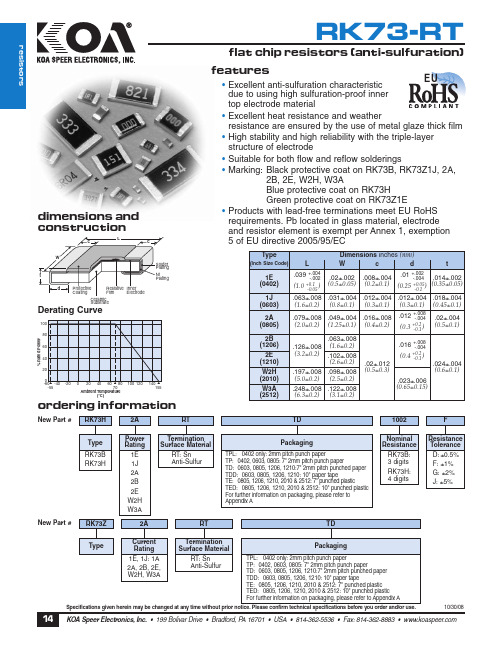
TD
1002
F
% Rated Power
Type RK73B RK73H
New Part # RK73Z
Power Rating
1E 1J 2A 2B 2E W2H W3A
2A
Termination Surface Material
RT: Sn Anti-Sulfur
RT
Packaging
TPL: 0402 only: 2mm pitch punch paper TP: 0402, 0603, 0805: 7" 2mm pitch punch paper TD: 0603, 0805, 1206, 1210:7" 2mm pitch punched paper TDD: 0603, 0805, 1206, 1210: 10" paper tape TE: 0805, 1206, 1210, 2010 & 2512: 7" punched plastic TED: 0805, 1206, 1210, 2010 & 2512: 10" punched plastic For further information on packaging, please refer to Appendix A
1E, 1J: 1A
2A, 2B, 2E, Wr
TPL: 0402 only: 2mm pitch punch paper TP: 0402, 0603, 0805: 7" 2mm pitch punch paper TD: 0603, 0805, 1206, 1210:7" 2mm pitch punched paper TDD: 0603, 0805, 1206, 1210: 10" paper tape TE: 0805, 1206, 1210, 2010 & 2512: 7" punched plastic TED: 0805, 1206, 1210, 2010 & 2512: 10" punched plastic For further information on packaging, please refer to Appendix A
酷玛QM3G YHSC 触摸屏PLC一体机使用手册说明书

感谢您购买 C oolmay QM3G 系列一体机。
本手册主要说明该系列触摸屏PLC一体机的产品特性、一般规格和接线方法。
详细PLC编程请参见《Coolmay QM3G 系列一体机编程手册》;触摸屏部分参见《Coolmay TP 系列人机界面使用手册》。
产品信息1公司产品系列 : 系列2HMI类型 43: 4.3寸 50: 5寸 70/70H D /70K : 7寸 100: 10寸3输入输出点数 16: 8入8出 24: 12入12出 38: 20入18出 44: 24入20出 60: 30入30出等4模块分类 M: 通用控制器主模块5开关量输出类型 R: 继电器输出类型; T: 晶体管(MOS 管)输出类型; RT: 混合输出6模拟量输入点数 43/50可选4路,70/HD 可选12路,70K /100可选16路 7模拟量输出点数 43/50可选2路,70/70HD /70K /100可选8路8模拟量输入类型 E : E 型热电偶K PT :PT100 PT1000:PT1000 NTC :热敏电阻(10K /50K /100K ) A0: 0-20mA电流 A4: 4-20mA电流 V5: 0-5V电压 V: 0-10V电压 V5_:-5V ~5V 电压 V _:-10~10V 电压【仅7寸和10寸的可选负电压输入】 9模拟量输出类型 A0: 0-20mA 电流 A4: 4-20mA 电流 V5: 0-5V 电压 V : 0-10V 电压 V5_:-5V ~5V 电压 V _:-10~10V 电压【仅7寸和10寸的可选负电压输出,且占用两路DA 】10. C1表示单相高速计数,C2表示AB 相计数,C3表示ABZ 相计数;11P 表示高速脉冲;P表示高速脉冲;12选装通讯口 参见【表一:基本参数】. . . . . . . . . . 常规8路,高速计数+高速脉冲总发不能超过480KHz .QM3G QM3G FH FH FH FH FH FH FH FH FH FH FH FH FH FH FH (可定制型/T 型/S 型/J 型,支持负温) 常规单相6路60KHz 或AB (Z )相2路30KHz +AB 相 1 路5KHz010KHz 100KHz Y0-Y3为100KHz ,Y4-Y7为10KHz ; 命名规则QM3G 43FH 图1 安装尺寸图QM3G -100FHQM3G -43FHQM3G -70KFH电气设计参考产品构造RUN :PLC运行指示灯COM PLC与触摸屏 : 通讯上时快闪QM3G -43FH图3图6 -70KFHQM3G 硬件接口安装尺寸机械设计参考输入为ON 输入为OFF 滤波功能高数计数功能有滤波功能,滤波时间在0-60ms范围内可设,默认是10ms开关量继电器输出指标允许最大电流回路电源电压电路绝缘On响应时间机械寿命(无负载)电气寿命(额定负载)2A /点,4A /4点 COM ,5A /8点 COM ,5A /12点 COMDC 30V以下/AC 220V以下继电器机械绝缘约10ms1000万次30万次开关量晶体管(MOS 管)输出指标允许最大电流回路电源电压电路绝缘隔离电压(电源-外部端子)On响应时间高速输出频率MOS 管: 2A /点, 4A /4点 C OM ,5A /12点C OM :MT :0.5A /点,0.8A /4点 C OM , 1.6A /12点 C OMDC24V 光耦绝缘1500VAC高速输出:10μs;其他:0.5ms 模拟量输入指标输入信号响应时间模拟量输入点数精度PT100/PT1000/热电偶/NTC/0-10V/0-5V /-10~10V /-5~5V /0-20mA/4-20mA/1个扫描周期0-16路12位模拟量输出指标输出信号模拟量输出点数精度0-5V/0-10V/0-20mA/4其他按客户要求定制信号等-10~10V /-5~5V /-20mA/0-8路12位外部接口通讯口环境条件工作温度相对湿度储存温度振动频率0°C~50°C5%~95%RH -20°C~70°C10-57Hz,振幅0.035mm; 57Hz-150Hz,加速度4.9m/s ² (X、Y、Z三方向各10次,合计各80分钟)基本参数触摸屏PLC一体机常见型号规格QM3G -43FH /50-16MR FH QM3G FH FH -70K /100-38M R QM3G FH FH --48M R 70K /100开关量模拟量(最大可选)通讯口(可选)高速计数高速脉冲DI DO AD DA 触摸屏PLC 单相AB相ABZ相输出2018242443FH /50FH:MT 为MOS 管输出;70FH /70HD 70KFH /100FH :MT 时Y0-Y3 为MOS 管输出,Y4-Y35 为晶体管输出;MR 为继电器输出;MRT 为混合输出。
RBK753 全家型三带无线网6系统说明书

Data SheetRBK753Whole Home Tri-band Mesh WiFi 6 SystemOverviewBreak free from limitations with strong,reliable, and lightning fast WiFi in every room of your home. From the top floor down to the basement, Orbi Tri-band Mesh WiFi 6 Systems bring you higher performance & simultaneous WiFi streaming, gaming & browsing on even more devices. This system includes NETGEAR Armor ™, advanced cyber security for your connected devices.Robust smart home WiFi.FeaturesCutting Edge Performance.Get the ultimate experience with 8 Streams of WiFi 6 a nd speeds up to 4.2Gbps.† Enjoy 4K/8K UHD streaming, l ag-free gaming & smooth streaming.It’s Easy.Enjoying your WiFi has never been easier. With the Orbi app, s et up your WiFi, customize your settings & enjoy your new O rbi WiFi in minutes.Gigabit Speeds Where You Need Them.Don’t let your home be a maze of dead zones. Get consistent speeds everywhere with Tri-band dedicated wireless backhaul & 8 Gigabit Ethernet ports.Cybersecurity With NETGEAR Armor ™.Protect your connected home devices from Internet threats with best-in-class anti-virus, anti-malware & data protection.1More Capacity, More Battery Life.Don’t be held back by limited capacity. Enjoy more devices simultaneously with 4X the capacity than before & improvedefficiency for longer battery life.Manage Your Kids’ Screen Time.NETGEAR Smart Parental Controls ™ let you easily manage your kids’ time online across their connected devices.2Data Sheet RBK753Whole Home Tri-band Mesh WiFi 6 SystemHouse DiagramRobustSmart Home ExperienceBuilt for Gigabit Internet Speeds EverywhereYou’ve paid for the fastest Internet speeds, now experience it everywhere in your home.Orbi AppUse the Orbi app to setup and manage your Orbi WiFi.NETGEAR Armor empowers you to eliminatevulnerabilities or simply know the status of your home network and devices, anytime, anywhere. Get instant notifications when malicious threats are detected, block unknown devices from joining your Orbi home network or take action on vulnerabilities as they are discovered easily through the Orbi App.Data SheetRBK753 Whole Home Tri-band Mesh WiFi 6 SystemOrbi Router (RBR750)Orbi Satellite (RBS750)Data Sheet RBK753Whole Home Tri-band Mesh WiFi 6 SystemWhat’s In the Box?• One (1) Orbi Router (RBR750)• Two (2) Orbi Satellites (RBS750)• One (1) 2m Ethernet cable• Three (3) 12V/2.5A power adapters • Quick start guideWhat Do I Need for Orbi to Work?• High-speed Internet connection• Connect to existing modem or gatewayTechnical Specifications• O rbi AX4200 Router & AX4200 Satellites (600 + 1200 + 2400Mbps)†• Simultaneous Tri-band WiFi - R adio 1: IEEE ® 802.11b/g/n/ax2.4GHz—1024-QAM support - R adio 2: IEEE ® 802.11a/n/ac/ax5GHz—1024-QAM support - R adio 3: IEEE ® 802.11a/n/ac/ax5GHz—1024-QAM supportPhysical Specifications• Dimensions: 9.1 x 7.2 x 2.8 in each • Weight: 1.9 lb eachSoftware Features• Orbi Mobile App• M U-MIMO capable for simultaneous data streaming • I mplicit & Explicit Beamforming for 2.4GHz & 5GHz bands• Processor - Router & Satellite - P owerful quad-core 1.4GHz processor • Memory – Router - 512MB NAND flash and 1GB RAM • Antenna – Router & Satellite (each) - S ix (6) high-performance internal antennas withhigh-power amplifiers • Ports – Orbi Router - T hree (3) 10/100/1000Mbps Gigabit EthernetLAN ports - O ne (1) 1Gbps Gigabit Ethernet WAN port • Ports – Orbi Satellite (each) - T wo (2) 10/100/1000Mbps Gigabit EthernetLAN ports • L ink aggregation using WAN port and a Gigabit Ethernet port • Security - C omprehensive anti-virus & data theftprotection for your PC, Mac ® and mobile devices with NETGEAR Armor ™-S tandards-based WiFi Security(802.11i, 128-bit AES encryption with PSK) - G uest WiFi Network is easy to setup separate &secure Internet access for guests • Voice Control - A mazon Alexa ™- The Google © Assistant • N ETGEAR Smart Parental Controls ™ — Manage your kids’ time online across their connected devices. Learn more at /spcThis product comes with a limited warranty that is valid only if purchased from a NETGEAR authorized reseller. /warranty *90-day complimentary technical support following purchase from a NETGEAR authorized reseller.‡Maximum wireless signal rate derived from IEEE 802.11 specifications. Actual data throughput and wireless coverage will vary and be lowered by network and environmental conditions, including network traffic volume, device limitations, and building construction. NETGEAR makes no representations or warranties about this product’s compatibility with future standards. Up to 4,200Mbps wireless speeds achieved when connecting to other 802.11ax 4,200Mbps devices. 1NETGEAR Armor ™ is free during the trial period. A yearly subscription, after the trial period, protects your connected devices. Visit /armor 2NETGEAR Smart Parental Controls™ fees apply for a Premium Plan. Visit /spc for more information. For regulatory compliance information, visit /about/regulatory For indoor use only.NETGEAR, the NETGEAR Logo, NETGEAR Armor, NETGEAR Smart Parental Controls, and Orbi are trademarks of NETGEAR, Inc. Apple and the Apple logo are trademarks of Apple Inc., registered in the U.S. and other countries. App Store is a service mark of Apple Inc., registered in the U.S. and other countries. Google Play and the Google Play logo are trademarks of Google LLC. Any other trademarks mentioned herein are for reference purposes only. © 2021 NETGEAR, Inc. NETGEAR, Inc. 350 E. Plumeria Drive, San Jose, CA 95134-1911 USA, /supportD-RBK753-3。
DAGE XD7800NT Ruby XL X-ray Inspection System 说明书
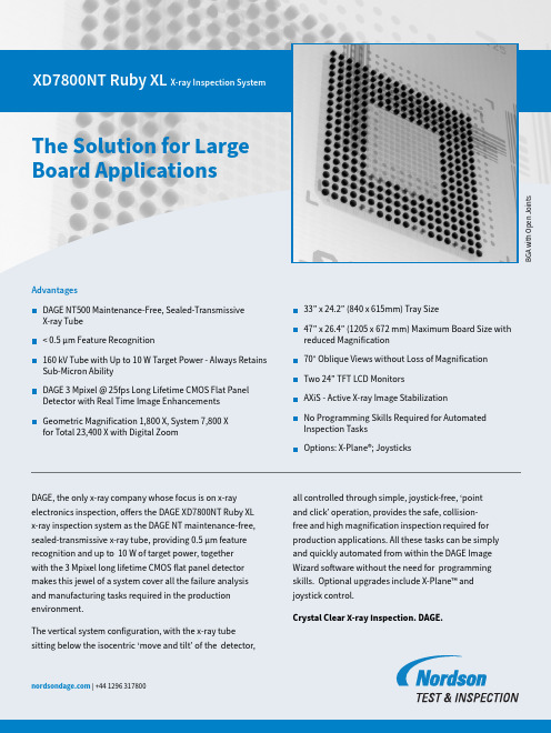
B G A w i t h O p e n J o i n t sXD7800NT Ruby XL X-ray Inspection SystemAdvantagesD AGE NT500 Maintenance-Free, Sealed-Transmissive X-ray Tube< 0.5 μm Feature Recognition160 kV Tube with Up to 10 W Target Power - Always Retains Sub-Micron AbilityD AGE 3 Mpixel @ 25fps Long Lifetime CMOS Flat Panel Detector with Real Time Image Enhancements G eometric Magnification 1,800 X, System 7,800 X for Total 23,400 X with Digital ZoomDAGE, the only x-ray company whose focus is on x-ray electronics inspection, offers the DAGE XD7800NT Ruby XL x-ray inspection system as the DAGE NT maintenance-free, sealed-transmissive x-ray tube, providing 0.5 μm feature The Solution for Large Board Applicationsall controlled through simple, joystick-free, ‘point and click’ operation, provides the safe, collision-free and high magnification inspection required for production applications. All these tasks can be simply 33” x 24.2” (840 x 615mm) Tray Size47” x 26.4” (1205 x 672 mm) Maximum Board Size with reduced Magnification70° Oblique Views without Loss of Magnification T wo 24” TFT LCD MonitorsAXiS - Active X-ray Image StabilizationNo Programming Skills Required for Automated Inspection TasksO ptions: X-Plane®; Joysticks For more information, speak with your Nordson representative or contact your Nordson regional officeAmericas+ 1 760 930 3307*********************Europe+44 1296 317800***************************China+86 512 6665 2008************************Germany+49 89 2000 338 270************************Japan+81 120 537 555************************Korea+82 31 462 9642***********************South East Asia+65 6552 7533************************Taiwan+886 2 2902 1860***************************United Kingdom+44 1296 317800***************************XD7800NT Ruby XL X-ray Inspection System Specifications• DAGE NT500 sealed-transmissive, filament-free x-ray tube:– < 0.5 μm feature recognition 30 - 160 kV for < 4 W target power– < 0.95 μm feature recognition when above 4 W target power– 10 W max. target power above 110 kV– automated tube stabilisation• 1,800 X geometric magnification (7,800 X system magnification)• 23,400 X total magnification including digital zoom• Easy, collision-free, high magnification inspection:– even at oblique angle views– joystick-free, ‘point and click’ operation• Tray size: 33” x 24.2” (840 x 615mm)• Maximum board size: 47” x 26.4” (1205 x 672 mm) with reduced magnification *Please refer to Dage for clarification for larger boards• Maximum inspection area: 33” x 24.2” (840 x 615mm)• 70° oblique angle views (over 30” x 24”, 762 x 610 mm):– for 360° around a point of interest– isocentric manipulator configuration keeps features in field of view • Long Lifetime CMOS digital detector with 1940 x 1530 pixels (3 Mpixels)– 25 fps full-frame ‘real time’ image acquisition– real time image enhancements• 16-bit digital image processing• AXiS - Active X-ray Image Stabilisation - anti-vibration control• Two off 24” TFT LCD operator display monitors• DAGE Image Wizard operating software including:– automated and manual component fault analysis including BGA & QFN– simple to create and use robust automated inspection routines– plated through hole (PTH) fill percentage calculation– accurate measurement functions– automated and manual die attach / area void calculation– patented1 X-ray navigation map for easy fault location– simple to use, no complicated joysticks required• Fully lead-shielded system safety cabinet– providing < 1 μSv/hr x-ray leakage– meets all international standards• 1 years system warrantyOptions• P atented X-Plane® 2• J oystick control (X,Y or X,Y & Z)• B arcode reader• 2nd Year warranty System• A pproximate Size: 94.5” x 98.5” x 81.5” (w x d x h)• A pproximate Size: 2400 x 2500 x 2070 mm (w x d x h)• A pproximate System Weight: 3000 kg (6600 lbs)• M aximum Sample Weight: 10 kg (22 lbs)• P ower: Single Phase 200 - 230Vac, 16A• M ax. P ower Consumption: 1000 W Max.• A ir: 4-6 bar of clean dry air for anti-vibration• O perating Temp. Range: 10 - 30ºC• H umidity: < 85% (non-condensing)1 EP 20632612 US 9129427 DS-RXL-110821。
T-CON三星T370HW02-VE-BN07-00644A-MEMC理图
CIS
2 1
PANEL_VCC
C111
R0041
3
R0050
NC
4
B12V
Close to U300
C0022 B0005 C0021 V12
RN002
LVDSORD AGBSEN
LVDSORD AGBSEN 1 PAD 1 YOE_S YOE4_S YOE3_S YCLK_S YDIO_S RST
CLKBP
CLKDP
CLKCP
TP1989
TP2003
PI_EVEN_RIN3P 1 PAD PAD
PI_ODD_RIN3P 1
AN3
BN3
DN3
CN3
PANEL_VCC
TP1994 RXINDN3 1 PAD PAD PAD SCL_GA1 SDA_GA1 PAD PAD PAD 1 1 1 RXINBN3 RXINCN3 RXINAN3
CIS
RXINCN2 RXINCP2 RXINCN[0..4] RXINCP[0..4] RXCLKCN RXCLKCP PANEL_VCC PAD RXINCN3 RXINCP3 RXINCN4 RXINCP4
IC101 1
S S S G D D D D 8 7 6 5
T1_LVP[0..2] T1_LVN[0..2]
X-BACK/RVN[4..6]
T1_RVCLKP T1_RVCLKN T2_RVP4 T2_RVN4 T2_RVP5 T2_RVN5 T2_RVP6 T2_RVN6
YV1C_S
XSTB_S
XPOL_S
B12V
4
4
CIS
GND EXSCL EXSDA R0047 RXINAN0 RXINAP0 RXINAN1 RXINAP1 R0046 RXINAN2 RXINAP2 R0048
山特产品速查手册说明书

山特产品速查手册SANTAK PRODUCT QUICK REFERENCE 全面保护用心为安全2 | 山特产品速查手册目 录Contents后备式UPSTG-E1000/500, TG1000/500, ET1100/550, K500/K1000 PRO, MT500/1000, TG-BOX 600/850, SP-BOX 在线式UPS塔式C1-3K, 塔式C6-10K, 3C 10-20K, 机架式C1-3kVA Rack, 机架式C6-10kVA Rack, 3C3 Pro (20-200kVA), 3C3 Pro ISO (15 -200kVA), 3C3 HD (20-80kVA), 3C3 HD (400-600kVA),SPU1-20K 电力行业专用 UPS, SIU 10-200K 山特工业级 UPS 灵霄系列PT 3000 (1-3kVA), PT 3000 (6-20kVA)模块式UPSARRAY 3A3 Pro 系列 (15~150kVA), ARRAY 3A3 PT 系列 (25~200kVA), ARRAY 3A3 PT 系列 (60~600kVA)蓄电池C12系列电池, G 系列胶体蓄电池, ARRAY 系列蓄电池, SBC-A 电池柜微模块灵聚2.0微模块产品系列, 灵聚 2.0 Aisle 配电机柜配电单元 (PDU)精密空调全变频小型精密空调 (7.5-20kW), 定频小型精密空调(7.5-20kW), 双轴流小型机房空调, 机房专用空调(25-100kW), 列间精密空调 (SMCRC 系列)机柜S 系列机柜移动电站3-1314-3839-4546-4950-5455-606162-7273 74-75山特后备式TG-E系列UPS⸺美观时尚的“设备守护神”。
TG-E500/1000 UPS功能强大,集智慧、安全、可靠于一身,提升消费者在产品品质、观感、质感方面的使用体验。
高亮度三色PLCC6黑体LED数据手册说明书

ASMT-YTC2-0AA02High Brightness Tricolor PLCC6 Black Body LEDData SheetDescriptionThe high brightness black top surface tri-color PLCC-6 family of SMT LEDs has a separate heat path for each LED dice, enabling the LED to be driven at higher current. These SMT LEDs are in the high brightness category, are high reliability devices, are high performance and are designed for a wide range of environmental condi-tions. By integrating the black top surface Avago devices deliver better contrast enhancement for your applica-tion. They also provide super wide viewing angle at 120° with the built in reflector pushing up the intensity of the light output. The high reliability characteristics and other features make the black top surface tri-color PLCC-6 family ideally suitable for exterior and interior full color signs ap-plication conditions.For easy pick & place, the LEDs are shipped in EIA-com-pliant tape and reel. Every reel is shipped from a single intensity and color bin; except red color providing betteruniformity. These tri-color LEDs are compatible with reflow soldering process.Featuresx Industry Standard PLCC-6 package (Plastic Leaded Chip Carrier) with individual addressable pin-out for higher flexibility of driving configuration x High reliability LED package with silicone encapsulation x High brightness using AlInGaP and InGaN dice technologies x Wide viewing angle at 120qx Compatible with reflow soldering process x JEDEC MSL 2ax Water-Resistance (IPX6*) per IEC 60529:2001* The test is conducted on component level by mounting the components on PCB with proper potting to protect the leads. It is strongly recommended that customers perform necessary tests on the components for their final application.Applications x Indoor full color display CAUTION: LEDs are Class 1C ESD sensitive. Please observe appropriate precautions during han-dling and processing. Please refer to Avago Application Note AN-1142 for additional details.Table 1. Device Selection GuidePart NumberColor 1 - AlInGaP Red Color 2 - InGaN Green Color 3 - InGaN Blue Min. Iv @20mATyp. Iv @ 20mA Max Iv @ 20mA Min. Iv @ 20mA Typ. Iv @ 20mA Max Iv @ 20mA Min. Iv @ 20mA Typ. Iv @ 20mA Max Iv @ 20mA Bin ID (mcd)(mcd)(mcd)Bin ID (mcd)(mcd)(mcd)Bin ID (mcd)(mcd)(mcd)ASMT-YTC2-0AA02T2355450715U1450560900R2140180285Notes:1. The luminous intensity I V , is measured at the mechanical axis of the LED package and it is tested in pulsing condition. The actual peak of the spatial radiation pattern may not be aligned with this axis.2. Tolerance = ± 12%Part Numbering SystemPackaging Option Color Bin Selection Intensity Bin Limit Intensity Bin SelectionDevice Specification Configuration Package Type C: Black Body Tricolor ColorT: TricolorProduce FamilyY: Silicone Based PLCC6Notes:1. All Dimensions are in millimeters2. Tolerance = ±0.2 mm unless otherwise specified3. Terminal Finish: Ag plating4. Encapsulantion material: silicone resin (Full Black Body)Lead Configuration1Cathode Blue 2Cathode Green 3Cathode Red 4Anode Red 5Anode Green 6AnodeBluePackage Dimensions10.534256Table 2. Absolute Maximum Ratings (T A = 25°C)Parameter Red Green & Blue Unit DC forward current [1] 5030mA Peak forward current [2]100100mA Power dissipation125114mW Reverse voltage4V[3]V Maximum junction temperature T j max125°C Operating temperature range -40 to + 110[4]°C Storage temperature range-40 to + 120°C Notes:1. Derate linearly as shown in Figure 4a & 4b.2. Duty Factor = 10% Frequency = 1KHz3. Driving the LED in reverse bias condition is suitable for short term only4. Refer to Figure 4a and figure 4b for more informationTable 3. Optical Characteristics (T A = 25°C)ColorDominant Wavelength,O d (nm) [1]Peak Wavelength,O p (nm)Viewing Angle2T½[2] (Degrees)Luminous EfficacyK V[3] (lm/W)Luminous EfficiencyK e (lm/W) Min Typ.Max Typ.Typ.Typ.Typ.Red61862262862912021022Green525530 53752112053525Blue465470477464120845Notes:1. The dominant wavelength is derived from the CIE Chromaticity Diagram and represents the perceived color of the device.2. T½ is the off axis angle where the luminous intensity is ½ the peak intensity3. Radiant intensity, Ie in watts / steradian, may be calculated from the equation Ie = I V / K V, where I V is the luminous intensity in candelas and K V isthe luminous efficacy in lumens / watt.4. )V is the total luminous flux output as measured with an integrating sphere at mono pulse condition.Table 4. Electrical Characteristics (T A = 25°C)ColorForward Voltage,V F (V) [1]Reverse VoltageV R @ 100P AReverse VoltageV R @ 10P AThermal ResistanceR T J-P (°C/W) [2] Min Typ.Max.Min.Min.TypRed 1.80 2.10 2.504–280 Green2.80 3.20 3.80–4180 Blue 2.80 3.20 3.80–4180 Notes:1. Tolerance ± 0.1V.2. One chip on thermal resistanceFigure 1. Relative Intensity vs Wavelength Figure 2. Forward Current-mA vs Forward Voltage-VFigure 3. Relative Intensity vs Forward CurrentFigure 4a. Maximum forward current vs. ambient temperature. Derated based on T JMAX = 125°C. (3 chips)Figure 4b. Maximum forward current vs. ambient temperature. Derated based on T JMAX = 125°C. (single chip)0.00.20.40.60.81.0WAVELENGTH - nmR E L A T I V E I N T E N S I T Y 020406080100FORWARD VOLTAGE-VF O R W A R D C U R R E N T -m A0.00.51.01.52.02.53.03.54.04.55.0DC FORWARD CURRENT-mAR E L A T I V E L U M I N O U S I N T E N S I T Y (N O R M A L I Z E D A T 20m A )010203040506020406080100120AMBIENT TEMPERATURE (°C)M A X A L L O W A B L E C U R R E N T -m A AlInGaPInGaN 0102030405060020406080100120AMBIENT TEMPERATURE (°C)M A X A L L O W A B L E C U R R E N T - m AAlInGaPInGaNFigure 5a. Radiation Pattern for X axisFigure 5b. Radiation Pattern for Y axisFigure 5c. Component Axis for Radiation PatternsFigure 6. Relative Intensity vs Junction Temperature Figure 7. Forward Voltage vs Junction TemperatureXX YYN O R M A L I Z E D L O P a t T J =25°C0.1110----0.0.F O R W A R D V O L T A G E S H I F T - VT J - J UNC TI ON TE MP E RA T UR E &T J - J UNC TI ON TE MP E RA T UR E &0.00.20.40.60.81.0-90-60-300306090ANGU L AR D I SP L AC E M E N T - D E GR EEN O R M A L I Z E D I N T E N S I T Y00.20.40.60.81ANGU L AR D I SP L AC E M E N T - D E GR EEN O R M A L I Z E D I N T E N S I T YFigure 8b. LED Configuration on land patternFigure 9. Recommended Pick and Place Nozzle TipTI METI MET E M P E R A T U R EFigure 10. Recommended leaded reflow soldering profile.Figure 11. Recommended Pb-free reflow soldering profile.Note: For detail information on reflow soldering of Avago surface mount LEDs, do refer to Avago Application Note AN 1060 Surface Mounting SMTLED Indicator ComponentsFigure 8a. Recommended soldering land pattern.I DI D = 1.7mm OD = 3.5mme fl o w l der ing i re cti o nFigure 12. Carrier tape DimensionFigure 13. Reel DimensionWITH DEPRESSION (0.25 mm)4.00P a ck a g e 10+–0.11101Figure 14. Reeling OrientationIntensity Bin LimitBin IDMin (mcd)Max (mcd)R2140.0180.0S1180.0224.0S2224.0285.0T1285.0355.0T2355.0450.0U1450.0560.0U2560.0715.0V1715.0900.0Tolerance for each bin limits is ±12%Color Bin Selection (X 2, X 3)Individual reel will contain parts from 1 half bin onlyX 2Min Iv Bin (Minimum Intensity Bin)RedGreenBlueAT2U1R2X 3Number of Half Bin from X 2RedGreenBlueA333Color Bin Selection (X 4)Individual reel will contain parts from 1 full bin onlyX 4Color Bin CombinationsRedGreenBlueFulldistributionA,B,CA,B,C,D,EPackaging Option (X 5)OptionTest CurrentReel Size220mA7 inchColor Bin Limits Red Color Bin TableBin IDMin DomMax DomFullDistribution618628x 0.68730.66960.68660.7052y0.31260.31360.29670.2948Tolerance of each bin limit is ± 1 nmGreen Color Bin TableBin IDMin DomMax DomA 525.0531.0x 0.11420.17990.21380.1625y 0.82620.67830.66090.8012B 528.0534.0x 0.13870.19710.22980.1854y 0.81480.67030.65070.7867C531.0537.0x 0.16250.21380.24540.2077y0.80120.66090.63970.7711Tolerance of each bin limit is ± 1 nmBlue Color Bin TableBin IDMin DomMax DomCorner Point1234A 465.0469.0x 0.13550.17510.1680.127y 0.03990.09860.10940.053B 467.0471.0x 0.13140.17180.16380.122y 0.04590.10340.11670.063C 469.0473.0x 0.12670.1680.15930.116y 0.05340.10940.12550.074D 471.0475.0x 0.12150.16380.15430.1096y 0.06260.11670.13610.0868E473.0477.0x 0.11580.15930.14890.1028y0.07360.12550.14900.1029Tolerance of each bin limit is ± 1 nmFor product information and a complete list of distributors, please go to our web site: Avago, Avago Technologies, and the A logo are trademarks of Avago Technologies in the United States and other countries.Data subject to change. Copyright © 2005-2010 Avago Technologies. All rights reserved. AV02-2589EN - October 5, 2010DISCLAIMER: Avago’s pro ducts and so ftware are no t specifically designed, manufactured o r autho rized fo r sale as parts, co mpo nents o r assemblies fo r the planning, co nstructio n, maintenenace o r direct o peratio n o f a nuclear facility or for use in medical devices or applications. Customer is solely responsible, and waives all rights to make claims against avago or its suppliers, for all loss, damage, expense or liability in connection with such use.Handling PrecautionThe encapsulation material of the LED is made of silicone for better product reliability. Since silicone is a soft material, avoid pressing on the silicon or poking the silicon with a sharp object as the product could be damaged and cause premature failure. During assembly handling, the unit should be held by the body only. Please refer to Avago Application Note AN 5288 for additional handling infor-mation and proper procedures.Moisture SensitivityThis product has a Moisture Sensitive Level 2a rating perJEDEC J-STD-020. Refer to Avago Application Note AN5305, Handling o f Mo isture Sensitive Surface Mo unt Devices, for additional details and a review of proper handling procedures.A. Storage before use– An Unopened moisture barrier bag (MBB) can be storedat <40°C/90%RH for 12 months. If the actual shelf life has exceeded 12 months and the humidity Indicator Card (HIC) indicates that baking is not required, then it is safe to reflow the LEDs per the original MSL rating.– It is recommended that the MBB not be opened prior to assembly (e.g. for IQC).B. Control after opening the MBB– The humidity indicator card (HIC) shall be read immedi-ately upon opening of MBB.– The LEDs must be kept at <30°C/60%RH at all times and all high temperature related processes including soldering, curing or rework need to be completed within 672 hours.C. Control for unfinished reel– Unused LEDs must be stored in a sealed MBB with desiccant or desiccator at <5%RH.D. Control of assembled boards – If the PCB soldered with the LEDs is to be subjected to other high temperature processes, the PCB need to be stored in sealed MBB with desiccant or desiccator at<5%RH to ensure that all LEDs have not exceeded theirfloor life of 672 hours.E. Baking is required if:– The HIC indicator is not BROWN at 10% and is AZURE at 5%.– The LEDs are exposed to condition of >30°C/60% RH atany time.– The Led floor life exceeded 672hrs.The recommended baking condition is: 60±5°C for 20hrs。
MN101E31G中文资料
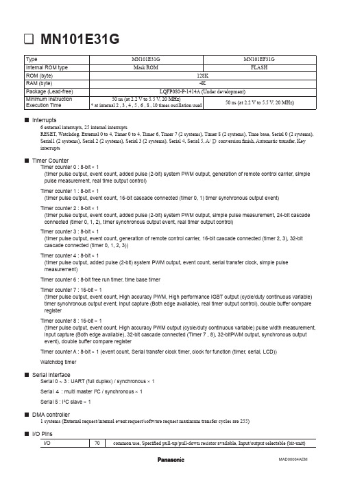
Timer Counter
Serial interface
Serial 0 ~ 3 : UART (full duplex) / synchronous × 1 Serial 4 : multi master I²C / synchronous × 1 Serial 5 : I²C slaveEG25 43
P57, KEY7, D7, SEG26 42
60
59
58
57
56
55
54
53
52
51
50
49
48
47
46
45
44
41
P47, SCL5B, SEG27
P61, SEG18
P74, SCL5A, NCS, SEG7 P75, SBO1B, TXD1B, A8, SEG6 P76, SBI1B, RXD1B, A9, SEG5 P77, SBT1B, A10, SEG4 P80, SDO0, A11, SEG3 P81, SDO1, A12, SEG2 P82, SDO2, A13, SEG1 P83, SDO3, A14, SEG0 P84, SDO4, A15, COM0 P85, SDO5, A16, COM1 P86, SDO6, A17, COM2 P87, SDO7, A18, COM3 P92, A19, VLC3 P93, NDK, VLC2 P94, SYSCLK, VLC1 P95 PB3, AN11 PB2, AN10 PB1, AN9 PB0, AN8
PA7, AN7
PA0, AN0, TM0IOA, RMOUTA
LQFP080-P-1414A
MAD00064AEM
P91, XO
RK73X1JTED1003D中文资料
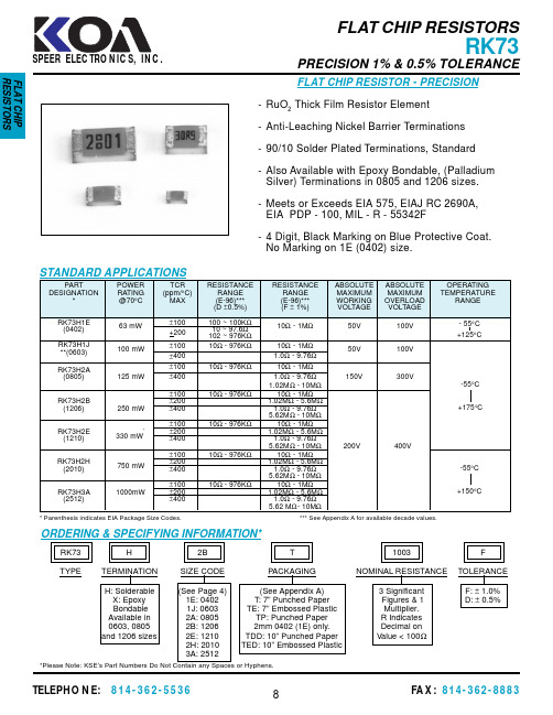
RK73H2B T 1003F TYPETERMINATION SIZE CODE PACKAGINGNOMINAL RESISTANCETOLERANCE H: Solderable (See Page 4)(See Appendix A) 3 Significant F: ± 1.0%X: Epoxy 1E: 0402T: 7” Punched Paper Figures & 1D: ± 0.5%Bondable 1J: 0603TE: 7” Embossed Plastic Multiplier.Available in 2A: 0805TP: Punched Paper R Indicates 0603, 08052B: 12062mm 0402 (1E) only.Decimal on and 1206 sizes2E: 1210TDD: 10” Punched Paper Value < 100Ω2H: 2010TED: 10” Embossed Plastic3A: 2512ORDERING & SPECIFYING INFORMATION*FLAT CHIP RESISTOR - PRECISION-RuO 2 Thick Film Resistor Element -Anti-Leaching Nickel Barrier Terminations -90/10 Solder Plated Terminations, Standard -Also Available with Epoxy Bondable, (Palladium Silver) Terminations in 0805 and 1206 sizes.-Meets or Exceeds EIA 575, EIAJ RC 2690A,EIA PDP - 100, MIL - R - 55342F-4 Digit, Black Marking on Blue Protective Coat.No Marking on 1E (0402) size.* Parenthesis indicates EIA Package Size Codes.*** See Appendix A for available decade values.*Please Note: KSE’s Part Numbers Do Not Contain any Spaces or Hyphens.AMBIENT TEMPERATURE(°C)ENVIRONMENTAL APPLICATIONS100806040202040608010012014016018070125150175DERATING¡¡¡% R A T E D P O W E R1E 1J, 2H, 3A 2A, 2B, 2E**RCWV = Rated Continuous Working Voltage125100755025255075100% RATED POWERT E M P E R A T U R E R I S E (°C )3A 2A 1J 1E2H2E2BSPEER ELECTRONICS, INC.FLAT CHIP RESISTORSDESCRIPTION OF CHIP RESISTORS -Eight (8) Available Sizes - 0201, 0402, 0603, 08051206, 1210, 2010, 2512-1/20 Watt to 1 Watt Power Ratings-0.1 Ohm to 22 Meg Ohm Resistance Range -Tight Tolerance and Low TCR Available -Excellent Solderability-Nickel Barrier for Leaching Control -Paper and Plastic Tape Packaging[1] Solder Plate, 90% Sn, 10% Pb[2] Barrier, NI [3] Electrode [4] Protective Layer[5] Resistive Element*NOTE: Dimensions are reference only.CONSTRUCTION & MECHANICAL DIMENSIONSLWHPTermination (Outer) [1] 120µin/3.0µm min.Termination (Barrier) [2] 120µin/3.0µm min.Termination (Inner) [3] 20µin/0.5µm min.[4] Protective Coating, 585µin/15µm [5] Resistive Element, 400µin/10µmAlumina SubstrateSPEER ELECTRONICS, INC.MARKINGFLAT CHIP RESISTORSPACKAGING & MARKINGPACKAGING SPECIFICATIONSMARKING contd.* Currently in the process of changing to 4-digit marking for both E-96 and E-24.SPEER ELECTRONICS, INC.FLAT CHIP RESISTORSTAPE & REEL SPECIFICATIONS(NOTES) DOTTED LINES ARE APPLICABLE ONLY FOR1E, 1J AND 2A SIZES ON 1000 PIECE REELS.CARRIER TAPEPACKAGING SPECIFICATIONSDIRECTION OF FEEDEMBOSSED CARRIED。
- 1、下载文档前请自行甄别文档内容的完整性,平台不提供额外的编辑、内容补充、找答案等附加服务。
- 2、"仅部分预览"的文档,不可在线预览部分如存在完整性等问题,可反馈申请退款(可完整预览的文档不适用该条件!)。
- 3、如文档侵犯您的权益,请联系客服反馈,我们会尽快为您处理(人工客服工作时间:9:00-18:30)。
RK73H
2B T 1003
F TYPE
TERMINATION SIZE CODE PACKAGING
NOMINAL RESISTANCE
TOLERANCE H: Solderable (See Page 4)(See Appendix A) 3 Significant F: ± 1.0%X: Epoxy 1E: 0402T: 7” Punched Paper Figures & 1D: ± 0.5%
Bondable 1J: 0603TE: 7” Embossed Plastic Multiplier.Available in 2A: 0805TP: Punched Paper R Indicates 0603, 08052B: 12062mm 0402 (1E) only.Decimal on and 1206 sizes
2E: 1210TDD: 10” Punched Paper Value < 100Ω
2H: 2010TED: 10” Embossed Plastic
3A: 2512
ORDERING & SPECIFYING INFORMATION*
FLAT CHIP RESISTOR - PRECISION
-RuO 2 Thick Film Resistor Element -Anti-Leaching Nickel Barrier Terminations -90/10 Solder Plated Terminations, Standard -Also Available with Epoxy Bondable, (Palladium Silver) Terminations in 0805 and 1206 sizes.-Meets or Exceeds EIA 575, EIAJ RC 2690A,EIA PDP - 100, MIL - R - 55342F
-4 Digit, Black Marking on Blue Protective Coat.No Marking on 1E (0402) size.
* Parenthesis indicates EIA Package Size Codes.*** See Appendix A for available decade values.
*Please Note: KSE’s Part Numbers Do Not Contain any Spaces or Hyphens.
AMBIENT TEMPERATURE
(°C)
ENVIRONMENTAL APPLICATIONS
100
80
60
40
20
204060
80100
120
140
160
18070
125
150
175
DERATING
¡
¡
¡
% R A T E D P O W E R
1E 1J, 2H, 3A 2A, 2B, 2E
**RCWV = Rated Continuous Working Voltage
125
100
75
50
25
255075100
% RATED POWER
T E M P E R A T U R E R I S E (°C )
3A 2A 1J 1E
2H
2E
2B
SPEER ELECTRONICS, INC.
FLAT CHIP RESISTORS
DESCRIPTION OF CHIP RESISTORS -Eight (8) Available Sizes - 0201, 0402, 0603, 08051206, 1210, 2010, 2512
-1/20 Watt to 1 Watt Power Ratings
-0.1 Ohm to 22 Meg Ohm Resistance Range -Tight Tolerance and Low TCR Available -Excellent Solderability
-Nickel Barrier for Leaching Control -Paper and Plastic Tape Packaging
[1] Solder Plate, 90% Sn, 10% Pb
[2] Barrier, NI [3] Electrode [4] Protective Layer
[5] Resistive Element
*NOTE: Dimensions are reference only.
CONSTRUCTION & MECHANICAL DIMENSIONS
L
W
H
P
Termination (Outer) [1] 120µin/3.0µm min.Termination (Barrier) [2] 120µin/3.0µm min.
Termination (Inner) [3] 20µin/0.5µm min.
[4] Protective Coating, 585µin/15µm [5] Resistive Element, 400µin/10µm
Alumina Substrate
SPEER ELECTRONICS, INC.
MARKING
FLAT CHIP RESISTORS
PACKAGING & MARKING
PACKAGING SPECIFICATIONS
MARKING contd.
* Currently in the process of changing to 4-digit marking for both E-96 and E-24.
SPEER ELECTRONICS, INC.
FLAT CHIP RESISTORS
TAPE & REEL SPECIFICATIONS
(NOTES) DOTTED LINES ARE APPLICABLE ONLY FOR
1E, 1J AND 2A SIZES ON 1000 PIECE REELS.
CARRIER TAPE
PACKAGING SPECIFICATIONS
DIRECTION OF FEED
EMBOSSED CARRIED。
