CERIAS Tech Report 2001-106 An open and safe nested transaction model concurrency and recov
斯伦贝谢新技术-2001年春季刊-套管井电阻率测井-Resistivity Behind Casing
CHFR 10Hz
0.25-
104
1Hz
CHFR High
HRLA HALS
15mm 0.2-0.6
5-
2. Brondel D Edwards R Hayman A Hill D Mehta
120
37
S Semerad T Corrosion in the Oil Industry
6
2 1994 4 4-18
0 -3A
5
13 m
> CHFR 6
CHFR
1
0.3m
5%
10-9 V
CHFR CHFR
10-9 V
CHFR
43
13m
3 3/
8
4 1/ 2
10 10-9
10-3 10-5
CHFR 10 1
70 120
2 CHFR
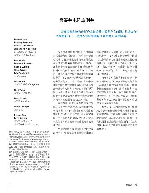
R t = 10 ohm- m R xo = 1 ohm-m R sh = 100 ohm-m
∆Rc ∆I
V
VV
R
o
1
2
c
CHFR
CHFR 2001
CHFR K
K CHFR
CHFR
( V1- V2) ( V 1,V 2 )
( V0 )
> CHFR
( Rc) (I) (∆I )
( Id )
5 -500 nV 20 -100 µV 10 - 100 mV 0.5 - 3.0 A 20 - 100 µoh m 0.5 - 6.0 A 2 - 20 m A
Vail WB III:Methods and Apparatus for Measurement of Electronic properties of Geological Formations through Borehole Casing
今年度も「蓄电池设备整备资格者」に1031名が合格
佐々木 雅俊 佐々木 優 佐々木 吉和 笹原 裕史 佐竹 弘幸 佐藤 淳 佐藤 競 佐藤 研 佐藤 忍 佐藤 昭一 佐藤 貴志 佐藤 哲夫 佐藤 裕覚 佐藤 宏之 佐藤 文俊 佐藤 雅俊 佐藤 真澄 佐藤 裕一 佐藤 雄典 佐藤 義樹 佐藤 義幸 里中 太作 實松 明彦 佐野 貴之 佐谷 克己 澤井 宏行 澤田 里志 澤田 寛明 残間 祐治 塩野 繁男 志賀 武史 重野 洋志 篠田 幸一 篠原 賢治 筱原 正俊 柴田 和義 芝田 正幸 柴原 秀一郎 澁田 政紀 渋谷 智士 志摩 浩利 島 有希 島添 謙 島田 元司 清水 慶太 清水 賢司 清水 智弘 清水 久義 清水 英明 下岡 一成 下川 孝一
平成23年度新規合格者
(あいうえお順・敬称略 )
青木 克典 青木 茂 青木 利久美 青木 寛明 青城 雅治 赤坂 陽一郎 阿形 幸信 赤平 健 秋山 孝行 秋山 久幸 浅井 孝弘 浅田 敬太郎 東 伸也 東 直之 安立 一幸 安立 佳一郎 足立 順 足立 旬 我妻 正一 阿部 勳 阿部 和弘 阿部 貴博 阿部 隆光 阿部 隆之 阿部 廣行 阿部 真和 安部田 剛 新井 敏夫 新井 敏浩 荒木 欽也 有賀 忠司 有賀 敏治 有福 健志 飯田 英行 飯田 健児 五十嵐 功一 五十嵐 正 五十嵐 規純 五十嵐 冬樹 池内 栄一 池田 一喜 池田 義邦 池谷 大志 池野 篤志 池部 徹男 池山 和男 伊佐 真一郎 井澤 友伸 石井 孝博 石井 規夫 石井 裕崇 石岡 雅洋 石川 盛文 石川 豊和 石川 勝 石榑 誠二 石黒 義英 石﨑 則孝 石田 大介 石田 正樹 石田 雅彦 石塚 清美 石橋 誠司 石橋 孝行 石橋 伸康 石原 歩 石丸 修一郎 石丸 昌男 泉谷 圭祐 一宇 正彦 市川 恵三 市川 輝彦 市川 直樹 市川 浩和 一瀬 常幸 井出 法之 出津 卓 伊藤 公一 伊藤 孝三 伊藤 伸二 伊藤 隆宏 伊東 直紀 伊藤 正樹 伊藤 雄一 伊藤 喜章 糸賀 大輔 稲垣 孝治 稲垣 岳人 稲毛 亮介 稲田 寿男 稲田 雅治 乾 太一 井上 芳 井上 智至 井上 潤 井上 誠 猪原 祐樹 猪又 聖明 今井 精治 今荘 貢 今村 敏也 今村 勇人 伊與 之敏 岩﨑 智成 岩﨑 正慈 岩下 薫 岩本 浩孝 上運天 祐樹 上岡 博志 上田 真義 植中 良成 上野 晃羅 上野 和樹 上野 圭介 上野 貴志 上野 正人 上原 修 上原 淳 上原 誠司 上間 司 請川 竜夫 潮 祐治 後田 孝文 碓井 哲治 碓井 治男 内田 章 内田 勲 内田 正行 内広 哲治 内山 松弘 梅川 浩 梅木 俊彦 梅田 耕市 梅津 佳祐 梅村 雅幸 宇山 隆久 浦川 正人 漆山 浩二 江川 重行 江口 輪 江原 郷 榎本 洋二 遠藤 和広 遠藤 貴志 遠藤 竜一 及川 喜世隆 及川 貴晴 大内 雄司 大久保 茂樹 大久保 正洋 大久保 義司 大倉 洋介 大島 在喜 大城 要 大城 健二 大城 正馬 大城 弘明 大曽根 英広 大田 和利 太田 金一 太田 天 太田 多加志 大田 法正 太田 博之 太田 勝 太田 幹雄 大谷 武志 大塚 祐矢 大槻 貴永 大坪 賢也 大坪 潤平 大中 和則 大西 一隆 大西 淳三 大西 庸久 大野 隆弘 大野 忠雄 大場 規広 大橋 健太郎 大橋 智一 大平 賢治 大渕 正和 大宮 亮 大山 康夫 大脇 泰成 大和田 薫 岡 知未 岡 竜司 魚返 孝文 岡﨑 隆広 岡田 誠司 岡野 啓一 岡野 隆 岡部 慶太 岡本 一則 岡本 光平 岡本 知哉 小川 英一 小川 佳寿男 小川 知也 小川 基樹 沖野 克嗣 荻原 智洋 奥田 法行 奥野 順一 奥野 道美 奥山 善行 小倉 敏伸 尾﨑 光 尾﨑 文昭 尾﨑 光俊 小澤 直浩 小沢 正明 尾関 基弘 小田 克仁 小田島 孝義 越智 一寿 越智 寛 音澤 悟 尾野 清 小野 智 小野 満 小野 友輝 小野田 敬明
ARTISAN技术集团的预览目录:IC200UEX636-C及GFK-1645H 11-1数字扩展单

GFK-1645H 11-1Analog Expansion UnitsThis chapter describes the following VersaMax Micro PLC Analog Expansion Units:▪ IC200UEX616 6 Point Analog Expansion Unit, (4) Analog In and(2) Analog Out, 12 VDC Power Supply▪ IC200UEX624 4 Point Analog Expansion Unit, (4) Analog In, 24 VDC Power Supply▪ IC200UEX6266 Point Analog Expansion Unit, (4) Analog In and(2) Analog Out, 24 VDC Power Supply▪ IC200UEX6366 Point Analog Expansion Unit, (4) Analog In and(2) Analog Out, 100/240 VAC Power SupplyGE FANUC SparesFeatures of Analog Expansion UnitsAnalog, Expansion Units have the features shown below. Expansion Units can belocated up to 2 meters from the Micro PLC.Removable Terminal StripsThe removable terminal assemblies are protected by hinged covers. After turningoff power to the Expansion Unit, a terminal assembly and attached field wiring canbe separated from the Expansion Unit by removing two screws.Expansion ConnectorThe connector on the left side of the Expansion Unit is used to connect to theMicro PLC or to the outgoing connector on the previous Expansion Unit. Theconnector on the right side of the Expansion Unit can be used to attach to the nextExpansion Unit.Status LEDsLEDs on the Expansion Unit provide quick visual verification of operating status.Expansion Unit LEDs indicate local Power and OK mode.CablesA 0.1 meter ribbon cable (IC200CBL501) is provided with each Expansion Unit.Cables are also available in 0.5 meter (IC200CBL505) and 1 meter(IC200CBL510) lengths.11-2 VersaMax® Micro PLCs and Nano PLCs User’s Manual – June 2008 GFK-1645HGFK-1645HChapter 11 Analog Expansion Units 11-3Analog Expansion Unit SpecificationsModule Dimensions Height: 90mm (3.6 inches), Depth: 76mm (3.0 inches) Width: 150mm (6.0 inches) Inputs 4 analog inputsOutputs2 analog outputs (all models except UEX624)Power Specifications for Analog Expansion UnitsIC200UEX616 IC200UEX624, UEX626IC200UEX636Power voltage 12VDC 24VDC 100/110/120/200/210/220V (50/60Hz) VACRange 9.6VDC - 15VDC 19.2VDC to 30VDC 85 to 264VAC Hold-up 10.1ms at 9.6V 24.5ms at 19.2V 223ms at 85V Inrush Current/Time 0.9A / 1ms at 15V 2.5V / 1ms at 30V 4A / 5ms at 264V Input Current 0.15A at 15V 0.1A at 30V 0.06A at 264V Input Power Supply Rating 2.25W 3W 15VA The DC power source must have enough transient current capability to support the inrush current of the power supply and to maintain the nominal voltage level.Input and Output SpecificationsAnalog Input Channels (IC200UEX6**) 4, differentialInput ranges0 to 10V (10.23V maximum)-10V to +10V ( -10.23V min. and +10.23V max.) 0 to 20mA (20.47mA maximum) 4 to 20mA (20.47mA maximum) Resolution 12 bitsAccuracy ±1% of full scale over full operating temperature range Linearity ±3 LSB maximum Isolationnon-isolated Common mode voltage ±40 V maximum Current input impedance 249 Ohms Voltage input impedance 200 kOhmsInput filter time20ms to reach 1% error for step input Analog Output Channels 2, single-ended, non isolated Output ranges0 to 10V (10.23V maximum) 0 to 20mA (20.47mA maximum) 4 to 20mA (20.47mA maximum) Resolution 12 bitsAccuracy±1% of full scale over operating temperature range Current: maximum terminal voltage user load range output load capacitance output load inductance 10V (at 20mA output) 10 to 500 ohms 2000 pF maximum 1 Henry maximumVoltage: output loading output load capacitance10 kOhm minimum at 10 volts 1 µF maximumGE FANUC Spares11-4 VersaMax® Micro PLCs and Nano PLCs User’s Manual – June 2008GFK-1645HAnalog OperationThis section explains how a VersaMax Micro PLC Expansion Unit with analog channels processes analog data. Unlike discrete expansion units, if one analog unit fails all subsequent analog expansion units will stop communicating.However, expansion units before the failed unit continue to be available. If an analog expansion fails at power up, no expansion units (discrete or analog) will be functional.Analog I/O ParametersEach analog channel can be configured to operate in either voltage or current mode. If current mode operation is selected, the range can then be configured as either 4-20mA or 0-20mA. If voltage mode operation is selected (inputs only), the range can then be configured as either 0-10V or –10V to +10V.Parameter Choices Default ValueVoltage or current mode Voltage, Current Voltage Current range selection4–20mA, 0–20mA 4–20mA Voltage range selection (Inputs Only)0-10V, -10-+10V0-10VInput/Output Values Compared to Process DataThe Expansion Unit processes analog channels using fixed conversion values for both current and voltage mode operation. The table below shows the relationship between the analog input and output values used by the application program, and the actual analog input or output for each mode. These values include the automatic adjustments for gain.In this ConfiguredMode: This is the Analog Signal Range This is the Equivalent Process Data %AI or %AQRangeFor the Default Calibration, theValue in the%AI or %AQ Reference Equals:Voltage 0 to +10V 0 to 10,000mV 0 to 32000 3.2 x mV Voltage –10 to +10V (Inputs Only) -10,000mv to +10,0000mV -32000 to 32000 3.2 x mV Current 0 to 20mA 0 to 20,000µA 0 to 32000 1.6 x µA Current 4 to 20mA4,000 to 20,000µA0 to 320002 x µA –8000GFK-1645HChapter 11 Analog Expansion Units 11-5Count Resolution for Analog Expansion UnitsFor analog expansion units, count resolution is controlled by a dip switch setting on the module. Switch 6 should be set to ON by default. If unexpected results are observed, check the position of switch 6. If switch 6 is not ON, power down the system and set switch 6 to ON. Do NOT change any of the other switches.LED IndicationsThe module’s LEDs indicate the status of the module and of the analog inputs.IN 1 IN2 IN3 IN4POW OKIf an initialization error occurs, the OK LED blinks rapidly. During normal operation, the analog input LEDs should be off.GE FANUC Spares11-6 VersaMax® Micro PLCs and Nano PLCs User’s Manual – June 2008GFK-1645HAnalog Input ProcessingThe Expansion Unit processes analog input channels with a 12-bit successive-approximation A/D converter. It converts the analog value into a digital count, calculates the %AI value as described below, then places the result into theappropriate %AI input reference (these references are described in chapter 21).Automatic Conversion of Analog Voltage or Current to CountsIn voltage mode, the Expansion Unit first converts the 0 to 10,000mV input signal to a count in the range of 0 to 4,000 (or –10,000mV to 10,000mV signal to a range of –4,000 to 4,000). The fixed multiplier for this conversion is 2.5.In current mode, the Expansion Unit first converts the 0 to 20,000µA input signal to a count value in the range of 0 to 4,000. The fixed multiplier for this conversion is 5. The conversion for both current modes (0-20mA and 4-20mA) is the same.Automatic Gain and Offset Adjustment for Analog InputsThe Expansion Unit then converts the A/D converter's input count value from the range of 0 to 4000 to a final %AI input value in the range of 0 to 32,000. Itmultiplies the count value by 8 (32000 / 4000) to get the final analog input ($AI):(input count X 8) = %AI valueAny calculated value above 32,767 is clamped at that maximum value. Any calculated value less than 0 is clamped at 0.Analog Input Conversion SummaryThe table below summarizes the conversion of voltage or current inputs to counts and then to %AI values.Input SignalConversion Factor A/D ConverterVAlueGain Factor %AI Range Voltage Mode (0 to 10,000mV) 2.50–4000 counts8 0–32,000 Voltage Mode (-10,000 to 10,000mV)2.5 -4000 to 4000counts8-32,000 to 32,000 Current Mode (0–20mA) or (4–20mA)5 0–4000 counts 80–32,000GFK-1645HChapter 11 Analog Expansion Units 11-7Analog Output ProcessingTo generate the analog output signal, the Expansion Unit converts the value in the %AQ output reference into a count value for the 12-bit D/A converter, which then drives the analog output.Automatic Gain and Offset Adjustment for Analog OutputsThe application's %AQ output range of 0 to 32000 corresponds to the D/Aconverter's output count range of 0 to 4000. The Expansion Unit first multiplies the %AQ value from the program by .125 (4000 / 32000) to produce the count value for the D/A converter:(%AQ X .125) = D/A countAny calculated value that exceeds 4095 (212-1) is clamped at that maximum value. Any calculated value less than 0 is clamped at 0. The range 0 to 4095 corresponds to %AQ values between 0 and 32,767.Automatic Conversion of Counts to Analog Voltage or CurrentIn voltage mode, the D/A converter then converts the count value in the range of 0 to 4,000 counts to an analog signal from 0 to 10,000mV. The output voltage gain (ratio) for this conversion is 2.5.In current mode, the D/A converter converts the count value to an analog signal from 0 to 20,000µA. The output current gain for this conversion is 5. The conversion for both current modes (0-20mA and 4-20mA) is the same.Analog Output Data Conversion SummaryThe table below summarizes the conversion of %AQ values to counts and then to voltage or current levels.%AQ Range Gain, Factor D/A Converter Range Conversion Factor Output Signal0– 32,000 0.125 0–4,000 counts 2.5 Voltage Mode (0–10,000mV) 0–32,0000.1250–4,000 counts5Current Mode (0–20mA)or (4–20mA)GE FANUC Spares11-8 VersaMax® Micro PLCs and Nano PLCs User’s Manual – June 2008GFK-1645HWiring DiagramPower Supply:UEX616: 12VDC UEX624: 24VDC UEX626: 24VDC UEX636: 100/240VACConnect jumpers in current mode2 Voltage or Current Analog OutputsOn modules IC200UEX616, UEX626 and UEX 636, voltage and current outputs are present on their respective output terminals at the same time. For proper module operation, only the output terminals that correspond to the voltage / current output configuration should be connected.。
李塞克检测中心
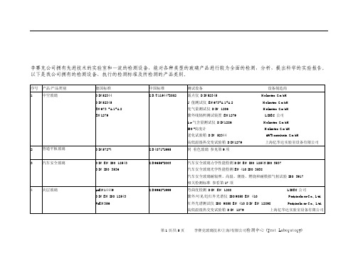
检测中心(Test Laboratory) 李赛克公司拥有先进技术的实验室和一流的检测设备,能对各种类型的玻璃产品进行较为全面的检测,分析,提出科学的实验报告。
以下是我公司拥有的检测设备、执行的检测标准及所检测的产品类别。
序号产品/产品类别德国标准中国标准测试设备设备制造商1 中空玻璃DIN52344DIN52345EN673 +A1+A2EN1279 GB/T11944-2002 露点仪DIN52345 Helantec GmbHU值测试仪 EN673+A1+A2 Helantec GmbH充气量测试仪 DIN 1286 Helantec GmbH紫外线辐照测试装置 EN1279 LISEC公司Ar气含量测试仪 DIN1286 Helantec GmbHISO-高度计 Helantec GmbH老化试验箱 DIN 52344 ift-Rosenheim GmbH高低温湿热交变试验箱 DIN1279 上海亿华达实验室设备有限公司2 普通平板玻璃DIN572-4 GB4871-1995 同着色玻璃参见第9项3 汽车安全玻璃DIN EN ISO 12543DIN ISO 3536 GB9656-2003 汽车安全玻璃力学性能检测 DIN EN ISO 12543 ISO 3537汽车安全玻璃光学性能检测 EN 410 ISO 3538汽车安全玻璃耐辐照、高温、潮湿、燃烧和耐模拟气候试验 ISO 3917相关检测标准参看第17项4 夹层玻璃prEN14449DIN EN ISO 12543PrEN356 GB9962-1999 弯曲度检测 DIN EN 1288 LISEC公司紫外/可见/近红外光谱仪 ISO9050 EN 410 Perkinelmer Co., Ltd.红外光谱测试仪 ISO 9050 EN 410 DIN EN 12898 Perkinelmer Co., Ltd.高低温湿热交变试验箱 DIN 1279 上海亿华达实验室设备有限公司落球冲击剥离试验 EN 356 DIN 12600 DIN 18032-3 DIN 52338 Torgauer GmbH 霰弹袋冲击试验 DIN 52337 Torgauer GmbH5 钢化玻璃DIN52337DRAFT prEN 14321EN 1288DRAFT prEN 14179-2DIN 12150DIN EN 1863 GB9963-1998 均质炉 pr EN 14179 Torgauer GmbH落球冲击剥离试验 EN 356 DIN 12600 DIN 18032-3 Torgauer GmbH霰弹袋冲击试验 DIN 52337 Torgauer GmbH颗粒度检测仪 DIN 52349 国家玻璃检测中心表面应力检测仪 DIN EN 1863 prEN 14321 杭州聚能玻璃技术有限公司.面电阻仪 DIN EN 12898 Nagy instrument GmbH锡面测试仪 Merlin Lazer Tgi弯曲度检测装置 DIN EN 1288 LISEC公司紫外/可见/近红外光谱仪 ISO9050 EN410 Perkinelmer Co., Ltd.红外光谱测试仪 ISO 9050 EN 410 DIN EN 12898 Perkinelmer Co., Ltd.6 幕墙用钢化玻璃DIN52349EN 1863-1 DRAFTprEN12150-2EN12600GB17841-1999 同钢化玻璃参看第5项7 低辐射镀膜玻璃EN 1096EN 12898 GB/T18915.2-2002 紫外气候试验箱 ISO3917 EN 1279 上海亿华达实验室设备有限公司盐雾试验箱 ISO 3917 EN 1279 ISO 21207 上海亿华达实验室设备有限公司高低温湿热交变试验箱ISO 3917 EN 1279 上海亿华达实验室设备有限公司摩擦试验机 DIN EN 1096 北京金博泰玻璃技术有限公司耐磨试验机 DIN EN 1096 上海现代环境工程技术有限公司铅笔硬度计 DIN EN 1096 上海现代环境工程技术有限公司附着力测试仪 DIN EN 1096 上海现代环境工程技术有限公司紫外/可见/近红外光谱仪 ISO 9050 EN 410 Perkinelmer Co., Ltd.红外光谱测试仪 ISO 9050 EN 410 DIN EN 12898 Perkinelmer Co., Ltd.X射线衍射仪 Bruker GmbH面电阻仪 DIN EN 12898 Nagy instrument GmbH锡面测试仪 Merlin Lazer Tgi热辐射率测试仪 DIN EN 12898 Material & service Co., Ltd膜面测试仪 Glavebel C.T.choy Co., Ltd酸碱实验杯8 阳光控制镀膜玻璃EN 410EN 1096DIN67507GB/T18915.1-2002 同低辐射镀膜玻璃参看第7项9 着色玻璃GB/T18701-2002 热辐射率测试仪 DIN EN 12898 Material & service Co., Ltd紫外/可见/近红外光谱仪 ISO 9050 EN 410 Perkinelmer Co., Ltd.红外光谱测试仪 ISO 9050 EN 410 DIN EN 12898 Perkinelmer Co., Ltd.10 浮法玻璃DIN572-2DRAFT prEN 14178-1GB11614-1999 同着色玻璃参看第9项---相关检测标准序号产品/产品类别DIN GB Test Device11 中空玻璃分子筛DIN 52294DIN EN 12145 GB10504GB6286GB10505.4GB10505.1GB6287-1986电子分析天平 DIN EN 12145 Monobloc inside Weighing technology co., Ltd马弗炉 DIN EN 12145 Nabertherm GmbH温度计 DIN 52294试管及称量杯 DIN 5229412 中空玻璃用弹性密封胶建筑用硅酮结构密封胶DIN52455DIN52459DIN EN ISO 9046DIN EN ISO 9047DIN EN 13880DIN EN 14187JC/T486-2001GB/T529-1999GB/T16776-1997GB/T14683JC/T485-1992B/T531-1999肖氏硬度计 DIN 52455 中国测试技术研究院实验工厂邵氏硬度计 DIN EN ISO 9046 DIN EN ISO 9047 时代集团公司拉力试验机 DIN EN 13880 DIN EN 14187 深圳三思实验室设备有限公司玻璃胶固化时间检测 DIN EN 14187 DIN EN 13880 LISEC公司13 丁基热熔密封胶ISO 2302 JC/T914-2003 ISO 230215 透过率,太阳光透过率,总能量透过率ISO 9050DIN67507GB/T2680-1994 紫外/可见/近红外光谱仪 ISO 9050 EN 410 Perkinelmer Co., Ltd.红外光谱测试仪 ISO 9050 EN 410 Perkinelmer Co., Ltd.16 颜色识别DIN 6174 GB/T11942 紫外/可见/近红外光谱仪 DIN 6174 Perkinelmer Co., Ltd.红外光谱测试仪 DIN EN 12898 Perkinelmer Co., Ltd.透射雾影仪 DIN 67507 BYK gardner GmbHColor-sphere 色差仪 DIN 6174 DIN 67507 BYK gardner GmbH18 酸碱,盐雾腐蚀试验ISO 21207 GB/T17339-1998 ISO2120719 幕墙光学性能检测GB/T18091-200020 水质检测ISO760 电导率测试仪 ISO 760铝条及其他测试21 环境温湿度测试仪r22 压力测试仪23 铝条检测轮廓投影仪万豪精密仪器有限公司.Al接插件测试杯 Al与胶拉力试验装置 Teroson GmbH 17 玻璃的力学光学及环境性能测试ISO 3537ISO 3538ISO 3917 GB5137 紫外/可见/近红外光谱仪 ISO9050 EN 410 Perkinelmer Co., Ltd.红外光谱测试仪 ISO9050 EN 410 DIN EN 12898 Perkinelmer Co., Ltd.透射雾影仪 ISO 9050 BYK gardner GmbHColor-sphere 色差仪 DIN 6174 BYK gardner GmbH紫外气候试验箱 ISO 3917 上海亿华达实验室设备有限公司盐雾试验箱 ISO 21207 上海亿华达实验室设备有限公司高低温湿热交变试验箱 ISO 3917 上海亿华达实验室设备有限公司摩擦试验机 EN 1096 北京金博泰玻璃技术有限公司耐磨试验机 EN 1096 上海现代环境工程技术有限公司老化试验箱 ISO 3917 ift-Rosenheim GmbH落球冲击剥离试验 EN 12600 Torgauer GmbH霰弹袋冲击试验 DIN 52337 Torgauer GmbH颗粒度检测仪 DIN 52349 国家玻璃检测中心需要了解详细情况,请联系我公司。
雷尼希亚RMP60机械工具接触测试探头系统说明书

• 2.4 GHz radio transmission, allows single system forworldwide use.• Interference-free channel hopping transmission.• No channel selection required. • RMP60 meets the radio regulations of:Europe: CE 0536! USA: FCC ID: KQGRMP60, FCC ID: KQGRMP60V2 FCC ID: KQGRMP60MV2 Japan: RMP60: 004NYCA0042, RMP60: 004NYCA0406 RMP60M: 004NYCA0407Canada: IC: 3928A-RMP60, IC: 3928A-RMP60V2Australia, China, Israel, New Zealand, Russia, Switzerlandand India.• Partner RMP60 and RMI systems allow interference-freemultiple probe installations.• The RMP60 is suitable for use with Renishaw single anddouble touch probing cycles.• User adjustable trigger force for long/cranked styli. • A weak link is included in each kit to protect the probein the event of excessive stylus overtravel, when using steel styli.• The RMP60 is a compact 3D touch-trigger probe(±X, ±Y , +Z sense directions) with radio transmission, used for workpiece set-up and inspection on small to large CNC machining centres and vertical turret lathes.• The RMP60 transmits omnidirectionally with a range of15 m (49.2 ft).• Ease of installation.• A standard battery life of 140 hours continuous use, orthe equivalent of approximately 100 days at 5 % usage is achievable. For applications requiring greater battery life, certain high capacity lithium thionyl chloride batteries can be used.• Repeatability, 1.0 µm (40 µin) is certified at480 mm/min (1.57 ft/min) with 50 mm stylus.• Probe switch on is user configurable between M code, spinor shank.• Probe switch off is user configurable between M code,time, spin or shank switch dependant on turn on method.StylusData sheet H-2000-2122-03-A A Tech Authoirty, Inc3857 Schaefer Ave, Ste C Chino, CA. 91710 (909)972-7520Operating envelope - RMP60/RMIThe RMP60 transmission envelope and range is shown below.The probe system should be positioned so that the optimum range can be achieved over the full travel of the machine’s axes including the tool magazine. Always face the RMI in the direction of the machine spindle and tool magazine. If the probe is not in range when in the tool magazine use spin or shank turn on.The RMP60 and RMI must be within a mutual operating envelope. The operating envelope shows line-of-sight performance. However, radio transmission does not require line-of-sight as long as any reflected radio path is less than the 15 m (49.2 ft) system operating range.RMP60 probeRange metres (feet)OPERATING AND SWITCH ON/OFF75°0°15°90°75°60°75°0°19 (0.75)50 (1.97)RMP60 dimensionsdimensions mm (in)ZData sheetRMP60 - radio probeBattery dead - at this stage probe status is forced open and the probe cycle will stop.System operationPrior to probe operation, it is imperative that the program selected to ‘drive’ the probe has been verified. Incorrect programming could result in damage to the machine, workpiece and probe system.The RMP60 probe operates in one of three modes:1. Stand-by mode - The RMP60 uses a small current,while waiting for a switch-on signal to be received.2. Operating mode - Activated by one of the methodsdescribed below. Signals are only transmitted by the probe in this mode and the probe is now ready for use.3. Configuration mode - Trigger Logic™ allows a numberof probe set-up options to be programmed, by triggering the probe when the batteries are inserted. Programmableoptions are described on the next page.Probe environmentPrimary application Inspection probe for machiningcentres Sense directions 5 way ±X ±Y +ZWeight (without a shank) with batteries without batteries901 g (31.79 oz) 855 g (30.16 oz)Trigger force using 50 mm (1.97 in) stylus low force direction factory settingX Y 0.75 N / 75 gf (2.65 ozf)Z 5.30 N / 530 gf (18.69 ozf)Trigger force using 50 mm (1.97 in) stylus high force directionX Y 1.4 N / 140 gf (4.94 ozf)Z 5.30 N / 530 gf (18.69 ozf)Max. spin speed 1000 rev/minOvertravel X Y 18°Z 11 mm (0.43 in)Sealing IPX8 (BS 5490, IEC 529)1 atmosphereRepeatability maximum 2σ value in any direction 1.0 µm (0.00004 in) is valid fortest velocity of 480 mm/min(1.57 ft/min) at stylus tip, usingstylus 50 mm (1.97 in) long.Probe specificationProbe status LEDsWhen operating the probe status LEDs give a visual indication of the probe state (triggered or seated) and battery condition.Multiple probe modeRMP60 can be user configured using T rigger Logic™ to allow multiple RMP60s to be used with a single RMI.Notes:Radio turn on cannot be used in multiple probe mode. RMP60s set to ‘mode-on’ can coexist alongside any number of RMP60’s set to ‘mode-off’.To allow multiple probes/single RMI in close proximity, 16 choices of ‘mode-on’ colours are available – each representing a different machine tool installation.Only one of the multiple probes per machine will need partnering as, by configuring multiple probes to a single‘mode-on’ choice, all probes have the same identification. The probe to be partnered is partnered after selection of multiple probe on mode.There is no limit to the number of probes that can be used with a single RMI as long as they all have the same ‘mode-on’ colour choice.All RMP60s are factory-set to ‘mode off’.The addition of further probe(s) into a single probe installation requires all probes to be re-configured to the same multiple probe ‘mode-on’ choice and the repartnering of one of the probes to the installed RMI.The addition of further probes (or replacements) into a multi probe installation is achieved simply by reconfiguration to the same ‘mode-on’ colour choice.Comprehesive details of how to set-up and change mutiple probe settings are included in the RMP60 installation and user's guide, H-2000-5219.RMP60/RMI Temperature Storage -10 °C to 70 °C (14 °F to 158 °F)Normal operating5 °C to 50 °C (41 °F to 122 °F)Notes:The RMP60 will be turned on after 1 sec in all modes.)After being turned on, the RMP60 must be on for a minimum of 1 sec (7 seconds for spin option) before being turned off. In radio on configuration (either radio on/radio off or radio on/time off) the RMP60 has a built-in hibernate mode. This saves battery life when the RMP60 is in stand-by and the RMI is un-powered (or out of range).The RMP60 goes into hibernate mode 30 sec after the RMI is un-powered (or out of range). When in this mode, the RMP60 checks for a powered RMI every 30 secs, if the RMI is found, the RMP60 goes from the hibernate mode to stand-by, ready for radio turn on.Probe switch on and offThe probe is switched on by one of the following options.All options are user configurable.RMP60 switch-on method.Switch-on options are configurable.RMP60 switch-off method.Switch-off options are configurable.1. Radio onRadio switch on is commanded by M code. (factory setting).1. Radio offRadio switch-off is commanded by M code. (factory setting).A timer automatically switches the probe off after 90 min from the last trigger, if not turned off by M code.2. Timer off (time out)The RMP60 will time out (12, 33 or 134 sec - user configurable) after the last probe trigger or reseat.2. Spin startSpin at 650 rev/min for 1 sec minimum (6 sec maximum).3. Spin stopSpin at 650 rev/min for 1 sec minimum (6 sec maximum).A timer automatically switches the probe off after 90 min from last trigger off.4. Timer off (time out)The RMP60 will time out (12, 33 or 134 sec - userconfigurable) after the last probe trigger or reseat.3. Shank switch5. Shank switch offBattery life expectancyTypical battery reserve lifeUsing the standard alkaline battery at 5% usage, typically the probe will continue to operate for approximately 1 week after a low battery warning is first indicated.Replace the batteries as soon as is practicable.Rechargeable batteries: either nickel metal hydride (NiMh) or nickel cadnium (NiCd) can be used, but expect a battery life of approximately 50% of the alkaline figures given in the table below.To achieve stated radio stand-by life, the RMP60 must be in-range of a powered partner RMI.Battery Shank/spin turn onRadio turn on Continuous useTwo AA type Stand-by life (days - typical)5% usage 72 minutes/day (days - typical)Stand-by life (days - typical)5% usage 72 minutes/day (days - typical)(hours - typical)Alkaline65010013065140Lithium ThionylChloride1300200260130280For applications requiring greater battery life, certain high capacity lithium thionyl chloride batteries can be used.Data sheetRMP60 - radio probe(Ø2.48)RMP60M is a special modular version of RMP60. It enables probe inspection of part features inaccessible to RMP60, by fitting selected adaptors and extensions as shown.RMP60M modular systemRMP60M dimensions40.75 50.00 / 100.00 / 150.00 66.25 (Ø2.48)100.00 / 150.00 / 200.00 50.50 (Ø2.48)66.25Parts list - Please quote the Part no. when ordering equipment.TypePart no.DescriptionRMP60A-4113-0001RMP60 probe with batteries, tool kit and user’s guide (factory set to radio on/radio off).RMP60M module A-4113-1003RMP60M probe with batteries, tool kit and user’s guide (factory set to radio on/radio off).Battery P-BT03-0005AA battery - Alkaline type supplied as standard with probe (two required).Battery P-BT03-0008AA battery - Lithium thionyl chloride (two required).Stylus A-5000-3709PS3-1C ceramic stylus 50 mm long with Ø6 mm ball.Weak link kit A-2085-0068Weak link (Part no. M-2085-0069 x 2) and 5 mm AF spanner.Tool kit A-4038-0304Probe tool kit comprising: Ø1.98 mm stylus tool, 2.0 mm AF hexagon key,2.5 mm AF hexagon key (x 2), 4 mm AF hexagon key, and shank grub screws (x 2).Diaphragm kit A-4038-0302RMP60 outer diaphragm.Battery cassette A-4038-0300RMP60 battery cassette assembly.Cassette seal A-4038-0301Battery cassette housing seal.Bobbin kit A-4038-0303Bobbin for shank switch (supplied with shank).RMI A-4113-0050RMI, side exit, with 15 m (49.2 ft) cable, tool kit and user’s guide.Mtg brkt A-2033-0830Mounting bracket with fixing screws, washers and nuts.Extension L100A-4038-1010RMP60M extension - 100 mm long.Extension L150A-4038-1027RMP60M extension - 150 mm long.Extension L200A-4038-1028RMP60M extension - 200 mm long.Probe module A-4038-1002RMP60M probe module assembly.RMP60/LP2 adaptor A-4038-0212RMP60M LP2 adaptor assembly.LPE1A-2063-7001LPE1 extension bar - 50 mm long.LPE2A-2063-7002LPE2 extension bar - 100 mm long.LPE3A-2063-7003LPE3 extension bar - 150 mm long.MA4A-2063-7600MA4 90° adaptor assembly.RMP60 user’s guide H-2000-5219RMP60 user’s guide.Styli –See brochure H-1000-3200 Styli and accessories.Software –See data sheet H-2000-2289 Probe software for machine tools.Shanks –See data sheet H-2000-2011 Shanks.RMI–See data sheet H-2000-2123 RMI.Renishaw plcNew Mills, Wotton-under-Edge, Gloucestershire GL12 8JR United KingdomT +44 (0)1453 524524F +44 (0)1453 524901E ***************© 2006 Renishaw plc. All rights reserved. Renishaw reserves the right to change specifications without noticeIssued 11.06 Part no. H-2000-2122-03-AFor worldwide contact details, please visit ourmain web site at /contact*H-2000-2122-03*。
风电叶片测试标准23中文

目录前言 (3)引言 (4)1.主题与范围 (5)2.引用标准 (5)3.定义 (5)4.符号 (8)4.1符号 (8)4.2 希腊符号 (8)4.3 下标符号 (8)4.4缩写词 (9)5 通用原则 (9)5.1试验目的 (9)5.2临界状态 (9)5.3实际约束 (10)5.4试验结果 (10)6叶片数据 (11)6.1概要 (11)6.2外部尺寸与接触面 (11)6.3 叶片特性 (11)6.4 材料数据 (12)6.5 设计负荷及条件 (12)6.6试验区域 (13)6.7 特殊的叶片修改 (13)6.8根部固定 (13)6.9机械装置 (13)7.设计和试验负荷条件的不同 (13)7.1 总述 (13)8.试验负荷 (15)8.1总述 (15)8.2 以负荷为基础的试验 (15)8.3以强度为基础的试验 (16)8.4负荷静态试验各方面 (17)8.5负荷疲劳试验各方面 (17)8.6静态和疲劳试验顺序 (18)8.7机械装置 (18)9试验负荷因素 (18)9.1概要 (18)9.2设计中使用的准安全因子 (18)9.3试验负荷因素 (19)9.4负荷系数的应用以获得目标负荷 (20)10 试验负荷分布之于设计负荷的评估 (20)10.1概要 (20)10.2 引入负荷的影响 (20)10.3静态试验 (20)10.4疲劳试验 (22)11故障状态 (24)11.1概要 (24)11.2灾难性故障 (24)11.3功能故障 (24)11.4表面故障 (24)12试验过程和方法 (25)12.1概要 (25)12.2试验台和根部固定装置要求 (25)12.3引入负荷的固定装置第38页图6 (25)12.4静态强度试验 (25)12.5疲劳试验 (26)12.6选择各种试验方法的优缺点 (28)12.7决定性修正 (28)12.8数据收集 (29)13决定叶片性质的其他试验 (30)13.1概要 (30)13.2试验台偏移 (30)13.3偏移 (30)13.4刚度分布 (30)13.5变形分布测量 (31)13.6固有频率 (31)13.7阻尼 (31)13.8形态 (31)13.9(物理)质量分布 (32)13.10蠕变 (32)13.11其他非破坏性试验 (32)13.12叶片分段 (32)14报告 (32)14.1概要 (32)14.2内容 (32)14.2.1通用---所有试验 (32)14.2.2静态试验和疲劳试验 (32)14.2.3其他试验 (33)附录A(常规性)准安全系数的考虑 (34)附录B(常规性)疲劳公式敏感性评估 (35)附录C(常规性)加载角度变化的考虑 (36)附录D(资料性)试验安装实例 (37)Bibliography (39)前言1)IEC(国际电工技术委员会)是由各国家电工技术委员会(IEC国家委员会)组成的世界性标准化组织。
基矛SPCE061A芯片的驻车加热系统设计

水 泵 电动 机 的转速 , 以达到 控 制水循 环 速度 的 目的 , 使得 该 系统具 有 自动化 程度 高 、 结构 紧凑 、 噪声 低 、 热
1 概 述
驻 车加 热 系统 最 早 风靡 欧洲 , 于欧 洲 一 些 国 由 家所 处 的地 理位 置特 点 , 冬季 气候 温 度特 别低 , 给 这 车 主带来 很 大 的不 便 。上 下 班 时 , 主 进 入寒 冷 的 车 车内, 很难 适 应其 温 度 , 手脚容 易 僵硬 , 响驾 车 ; 影 更 严重 的是 , 箱在 低 温环境 下 被冻 而使 启 动较难 , 水 给 车主 不仅 造成 不便 , 会造 成 机械磨 损 , 还 导致 以下后 果 :)低 温 下发 动 机 动力 性 、 济 性 和 排 放 质 量 都 1 经 很差 ;)环境 温 度在 9 2 O℃ 以下 , 动 机工 作 时 的磨 发
L 一
因此 , 的外 形 尺寸 和质量 大大 降低 , 泵 能够 适 用于各
种 液体 的添加 。
极 强 的耐 化 学 性 能 的泵 头 材 质 有 P VC、 R GF —
P
P P P、 VDF和 S US可供 选 择 。同 时所 有 的接 液端材
质 都需 具有 极 好 的 耐腐 蚀 性 , 哈 氏合 金 C 6 、 有 2 7 陶
2 )自动化 : 热 更便 捷 , 预 先进 的遥 控 、 时 系统 定 随 时轻松 地 为爱 车加 热 。 3 )保 护性 : 免低 温冷 启动 给 发动 机 带来 的磨 避 损 。据研 究 表 明一 次 冷启 动带 来 的发动 机磨损 相 当
用于形成射频陶瓷块滤波器的烧蚀方法[发明专利]
![用于形成射频陶瓷块滤波器的烧蚀方法[发明专利]](https://img.taocdn.com/s3/m/a475f33b5022aaea988f0fa9.png)
专利名称:用于形成射频陶瓷块滤波器的烧蚀方法
专利类型:发明专利
发明人:R·G·布莱尔,E·J·罗姆巴赫,R·N·西蒙斯,W·D·帕斯科申请号:CN00810420.4
申请日:20000612
公开号:CN1363125A
公开日:
20020807
专利内容由知识产权出版社提供
摘要:在电介质材料块上形成金属化图案的方法,其中,电介质块的整个表面区域用导电材料包裹,而不需要的导电金属从电介质块的指定表面区域被烧蚀刻蚀掉,以形成所需要的金属化电路图案。
本发明还包括用本发明的方法形成的滤波器和双工器。
申请人:CTS公司
地址:美国印第安纳州
国籍:US
代理机构:中国专利代理(香港)有限公司
更多信息请下载全文后查看。
- 1、下载文档前请自行甄别文档内容的完整性,平台不提供额外的编辑、内容补充、找答案等附加服务。
- 2、"仅部分预览"的文档,不可在线预览部分如存在完整性等问题,可反馈申请退款(可完整预览的文档不适用该条件!)。
- 3、如文档侵犯您的权益,请联系客服反馈,我们会尽快为您处理(人工客服工作时间:9:00-18:30)。
CERIAS Tech Report 2001-106An open and safe nested transaction model: concurrency and recovery by S Madria, S Maheshwari, B Chandra, B BhargavaCenter for Education and ResearchInformation Assurance and SecurityPurdue University, West Lafayette, IN 47907-2086An open and safe nested transaction model:concurrency andrecoverySanjay Kumar Madria a,*,S.N.Maheshwari b,B.Chandra c,Bharat Bhargava aa Department of Computer Science,Purdue University,West Lafayette,IN47907,USAb Department of Computer Science and Engineering,Indian Institute of Technology,Hauz Khas,New Delhi,Indiac Department of Mathematics,Indian Institute of Technology,Hauz Khas,New Delhi,IndiaReceived1August1999;received in revised form1November1999;accepted8December1999AbstractIn this paper,we present an open and safe nested transaction model.We discuss the concurrency control and recovery algorithms for our model.Our nested transaction model uses the notion of a recovery point subtransaction in the nested transaction tree.It incorporates a prewrite operation before each write operation to increase the potential concurrency.Our transaction model is termed``open and safe''as prewrites allow early reads(before writes are performed on disk)without cascading aborts.The systems restart and bu er management operations are also modeled as nested transactions to exploit possible concurrency during restart. The concurrency control algorithm proposed for database operations is also used to control concurrent recovery operations.We have given a snapshot of complete transaction processing,data structures involved and,building the restart state in case of crash recovery.Ó2000Elsevier Science Inc.All rights reserved.1.Introduction1.1.Overview of nested transaction models and recovery algorithms1.1.1.Close nested transaction modelIn close nested transaction model(Moss,1985),a subtransaction may contain operations to be performed concurrently,or operations that may be aborted inde-pendent of their invoking transaction.Such operations are considered as subtransactions of the original trans-action.This parent±child relationship de®nes a nested transaction tree and transactions are termed as nested transactions(Moss,1985).Failure of subtransactions may result in the invocation of alternate subtransactions that could replace the failed ones to accomplish the successful completion of the whole transaction.Each transaction has to acquire the respective lock before accessing a data object.A subtransaction's e ect cannot be seen outside its parent's view(hence,called closed).A child transaction has access to the data locked by its parent.When a transaction writes a data object,a new version of the object is created.This version of the ob-ject is stored in volatile memory.When the subtrans-action commits,the updated versions of the object are passed to its parent.If the transaction aborts,the new version of the object is discarded.Parent commits only after all its children are terminated.When the top-level transaction commits,the current version of each object is saved on stable storage.In the closed nested transaction model,the avail-ability is restricted as the scope of each subtransaction is restricted to its parent only.This forces a subtransaction to pass all its locks and versions of data objects updated to its parent on commit.The e ect of a committed subtransaction is made permanent only when the top-level transaction commits.In many applications,it is unacceptable that the work of a longlived transaction is completely undone by using either of the above tech-niques in case the transaction eventually fails at®nishing stage.The current strategy forces short-lived transac-tions to wait before they acquire locks until the top-level transactions commit and release their locks.Therefore, the model is not appropriate for the system that consists of long and short transactions.The Journal of Systems and Software55(2000)151±165/locate/jss*Corresponding author.Present address:Department of ComputerScience,University of Missouri,Rolla,MO65405,USA.E-mail addresses:madrias@,skm@(S.K.Madria),snm@cse.iitd.ernet.in(S.N.Maheshwari),bchan-dra@maths.iitd.ernet.in(B.Chandra),bb@(B.Bharg-ava).0164-1212/00/$-see front matterÓ2000Elsevier Science Inc.All rights reserved.PII:S0164-1212(00)00067-41.1.2.Open nested transaction modelTo exploit layer speci®c semantics at each level of operation nesting,Weikum presented a multilevel transaction model(Weikum,1991;Weikum et al.,1990). The model provides non-strict execution by taking into account the commutative properties of the semantics of operations at each level of data abstraction,which achieves a higher degree of concurrency.A subtransac-tion is allowed to release locks before the commit of higher level transactions.The leaf level locks are re-leased early only if the semantics of the operations are known and the corresponding compensatory actions de®ned.When a high level transaction aborts,its e ect is undone by executing an inverse action which compen-sates the completed transaction.Recovery from system crashes is provided by executing undo actions at the upper levels and redo actions at the leaf level.Each level is provided with a level speci®c recovery mechanism. This model has also been studied in the framework of object oriented databases in Muth et al.(1993)and Resende et al.(1994).In many applications,the semantics of transactions may not be known and hence,it is di cult to provide non-strict executions.In real time situations,there are other classes of operations that cannot be compensated. These are the operations that have an irreversible ex-ternal e ect,such as handing over huge amounts of money at an automatic teller machine.Such operations have to be deferred until top-level commits,which re-stricts availability(i.e.,increases response time).1.1.3.Nested transaction recovery algorithmsThe intentions-list and undo-logging recovery algo-rithms given in Fekete et al.(1993)handle recovery from transaction aborts in the nested transaction environment by exploiting the commutative properties of the opera-tions.The intentions-list algorithm works by maintain-ing a list of operations for each transaction.When a transaction commits,its list is appended to its parent; when it aborts,the intentions-list is discarded.When the top level transaction commits,its intentions-list is transferred to the log.This scheme provides recovery from transaction aborts only and does not handle sys-tem crashes.To increase concurrency during undo log-ging recovery,scheme allows some non-strict executions.It allows a transaction to share the uncom-mitted updates made by other transactions by exploiting commutativity of operations.On execution of an oper-ation,the data object records change their states and the new state is transferred to the log.When a transaction aborts,in contrast to intentions-list algorithm,all op-erations executed by its descendants on the object are undone from its current state and are also subsequently removed from the log.This algorithm does not take care of recovery from system crashes.In both intentions-list and undo-logging algorithms, an incomplete transaction is allowed to make uncom-mitted updates available to those transactions that per-form a commutative operation.However,this is restricted to transactions at the same level of abstrac-tion.This limits availability.In both algorithms,all the work done by descendent transactions are discarded in case of aborts at higher levels.This may not be possible or desirable in many real time applications.In undo-logging algorithm,when a transaction aborts,in con-trast to intentions-list algorithm,all operations executed by its descendants on the object are undone from its current state and are subsequently removed from the log.In both intentions-list and undo-logging algorithms, an incomplete transaction is allowed to make uncom-mitted updates visible to those transactions that perform a commutative operation.This is restricted to the transactions at the same level of abstraction.The above two recovery models consider semantics of operations at leaf level only.System R(Gray et al., 1981)exploits layer speci®c semantics but restricted to two level of transaction nesting.In System R,to per-form recovery,updates are undone by performing in-verse tuple-level operations.For this purpose,System R records tuple updates on a log.To recover from a system crash,before applying any tuple level log record,the database must®rst be restored to some tuple-level consistent state.In other words,a low-level recover mechanism is necessary to make tuple actions appear atomic.In Moss(1987),a crash recovery technique similar to shadow page has been suggested in nested transaction environment based on undo/redo log methods.In terms of logging,both undo/redo logs are used.Mohan et al. (1992,1989)has also discussed``write ahead logging'' based crash recovery algorithm using conventional nested transaction model.This undo/redo type of re-covery model exploits semantics of nested transactions. The actions of a transaction undone during previous abort have not been undone again in case of one more failure.This is an advantage over Weikum's multilevel recovery algorithm by which requires undo actions to be undone again in case of one more failure.1.2.Our contributionsIn this paper,we introduce an open and safe nested transaction model in the environment of normal read and write operations to remove the de®ciencies stated above and to further improve availability and provide e cient crash recovery.Our model supports inter-and intra-transaction concurrency.We assume that seman-tics of transactions at various levels of nesting are not known.There are two basic motivations behind our model.First,it is desirable that long-lived transactions should be able to release their locks before top-level152S.K.Madria et al./The Journal of Systems and Software55(2000)151±165transactions commit.Second,it may not be desirable or possible to undo or compensate the e ects of one or more of the important committed descendants after the failure of a higher level transaction due to abort or a system crash.We introduce the concept of a``recovery point subtransaction''of a top-level transaction in a nested transaction tree.It is essentially a subtransaction after the commit of which its ancestors are not allowed to rollback.In other words,once the recovery point subtransaction of a top-level transaction has committed, all its superior transactions are forced to commit.In case it aborts,its ancestors can choose an alternate path to complete their execution.Our nested transaction model uses a prewrite operation before an actual write opera-tion to increase the concurrency.The nested transaction tree of our model consists of database operations,sys-tem recovery operations(such as analysis and redo op-erations)and bu er management operations speci®ed as nested transactions.The read,prewrite and writes op-erations are modeled at leaf levels in the transaction hierarchy.The recovery operations are speci®ed in terms of nested transactions to achieve higher concurrency during system restart.Our locking algorithm controls the execution of both the normal operations as well as recovery operations.We also discuss the data structures required for the implementation of the recovery algo-rithm.We have discussed a snapshot of the concurrency and recovery algorithm with the help of an example.A brief overview of our crash recovery algorithm has ap-peared in Madria et al.(1997c).The correctness of the concurrency control algorithm using I/O automation model(FLMW)has reported in Madria et al.(1997b). The rest of the paper is organized as follows.In Section2,we present motivating examples and the overview of our nested transaction and recovery model. In Section3,we discuss nested transaction system model and implementation.Section4presents system restart operations.We present a snapshot of transaction pro-cessing,logging and recovery in Section5.We conclude in Section6.2.Open and safe nested transaction model and recovery algorithmIn this section,we motivate the readers about the open and safe nested transaction model with some ex-amples and provide an overview of our model and re-covery algorithm.Motivating examples:Consider a part of the nested transaction tree for fund transfer operation from a group of accounts to another account.In the transaction tree,let T s be a transaction on whose behalf T s1invokes various subtransactions to collect(access)funds from di erent accounts.Once T s1is committed,T s invokes T s2 to®nally credit the funds collected into another account.Suppose after a subtransaction T w has withdrawn all the amount,T s commits.If any transaction situated above T s aborts then it is desirable for the transaction to complete successfully on transaction revival.This is because it is not possible to undo or correct the failed transaction's action by some compensatory actions.Another possi-bility is to delay the actual commit of T s until its top-level transaction commits which restricts availability. For example,a balance transaction has to wait until the commit of the top-level transaction.Consider another scenario where in the nested transaction tree,a subtransaction determines the success (commit)or failure(abort)of the top level transaction. Suppose this nested transaction tree models various activities(modeled as subtransactions here)related to a business travel.Some of the activities are very crucial in determining the completion of the top level activity.For example,the commit of``fund''and``visa''subtransac-tions will determine whether the travel transaction will commit or not.That is,these subtransactions commit will determine the commitment of the top level trans-action no matter what may be the fate of other sub-transactions in the transaction tree.Note that once,the fund and visa subtransaction commits,its upper level (sub)transactions will be forced to commit(some delay or restart may involve).Salient features of our model:Our model allows some particular subtransactions to release their locks before their ancestor transactions commit.This allows the other subtransactions to acquire required locks earlier. Our nested transaction model can handle the situations where a committed lower level subtransaction's e ect cannot be undone or compensated in case of a higher level transaction's failure.A transaction's semantics may be such that beyond a certain point,it cannot rollback entirely or its e ect should not be lost.We achieve this by introducing the concept of``recovery point subtransaction''of a top-level transaction in a nested transaction tree.It is essentially a subtransaction after whose commitment,its ancestors are not allowed to rollback.In case a superior transaction aborts or the system fails after the commit of its recovery point sub-transaction,the failed transaction has to complete on system revival.Such a transaction execution permits a recovery point subtransaction to reveal its result to other transactions at any level of nesting before its su-perior transactions commit.A recovery point subtrans-action's e ect is made durable before its top-level transaction's commit.This results in the relaxation of the isolation property(Harder and Reuter,1983)of the transaction.To avoid undo actions and the consequent cascading aborts and to increase the availability,we assume that each transaction issues a prewrite operation(Madria, 1995;Madria et al.,1999;Madria and Bhargava,1997a) before a write for the object it intends to write.EachS.K.Madria et al./The Journal of Systems and Software55(2000)151±165153prewrite operation contains the value that a user-visible transaction wants to write and precedes the associated ®nal write.A prewrite operation actually does not change a data object's state but only announces the value the data object will have after the associated write is performed.The advantage of prewrite is that a read operation of another transaction can get the value be-fore a data object's state is updated on stable storage and hence,results in increasing the availability of new data values.Prewrite operations are particularly helpful in the engineering design applications(Kim et al.,1984), CAD(Korth et al.,1990),large software design projects (Korth and Speegle,1990)etc.where transactions are long.A subtransaction that initiates di erent prewrite access subtransactions at leaf level for di erent data objects is de®ned to be the recovery point subtransac-tion.These announced prewrite values are made visible to other subtransactions after the commit of recovery point subtransaction.The prewrite subtransactions re-lease their locks before their ancestors commit.Dis-carding some of the prewrites before the commit of the recovery point subtransaction will not introduce cas-cading aborts(hence safe)since the prewrite values are made visible only after the commit of the recovery point subtransaction.2.1.Crash recovery algorithm2.1.1.Basic goals of system crash recovery algorithm ·Revive the database state of those data objects which do not contain their last committed values with re-spect to the execution up to the system failure.·Revive the prewrite values(kept in prewrite-bu ers) of the data objects which have been announced by the committed recovery point subtransaction before system failure.·To identify such data objects,the dirty object table has to be revived.The dirty object table is used to keep track of those data objects whose®nally written values are inconsistent with the stable database val-ues.This table also keeps information about those data objects whose prewrite values,announced by the committed recovery point subtransactions,have not been subsequently written on the database before a system crash.·A system crash creates an additional problem of ac-complishing the completion of those top-level trans-actions whose recovery point subtransactions have been committed before system crash.They have to re-acquire the locks held by them at the time of failure before new transactions acquire such locks.·To handle above,the transaction and lock tables have to be revived.The transaction table keeps a list of all active transactions in the system at any time. The revived transaction table will recognize those ac-tive top-level transactions(and their active descen-dants)whose recovery point subtransactions have been committed before failures.The lock table con-tains the type of locks held by the transactions on dif-ferent data objects at any time.The revived lock table will help in reacquiring the locks held by active top-level transactions and their descendants at the time of failure.·To initiate new top-level transactions as soon as the dirty object,transaction,and lock tables and consis-tent states of prewrite-and write-bu ers of dirty data objects are re-established.2.1.2.System crash recovery stepsTo achieve above recovery goals,we need the fol-lowing steps to restart the system:Revival of dirty object table:The dirty object table is required to be checkpointed periodically by transferring a copy of it to the stable storage during normal pro-cessing.The prewrite values and after-images are logged on stable storage during the execution of transactions to build the consistent dirty object table in case a system failure occurs before the next checkpoint is taken.A transaction is not permitted to complete its commit processing until the redo portion of that transaction has been written to stable storage.The redo portion of a log record provides information on how to redo changes performed by the committed transactions.During sys-tem restart,the dirty object table is recovered with the help of most recent checkpointed copy of the dirty ob-ject table and is modi®ed with the help of log stored after the last checkpoint.Revival of transaction and lock tables:The transaction and lock tables are checkpointed by transferring a copy of each of them to the stable storage periodically during normal processing.Whenever a subtransaction is made active or when any transaction acquires or releases a lock,the information is also logged to build a consistent state of these tables.However,such information may not be logged for read-only and prewrite access sub-transactions as these are to be discarded in case of a system failure.If a checkpoint is taken during restart recovery then the contents of transaction and lock tables will also be included in checkpoint.The entries corre-sponding to all other transactions except those that are to be restarted(whose recovery point subtransactions have not been committed)are removed from the trans-action and lock tables.To do so,we need to®nd whether the stable storage contains the commit-state of the recovery point subtransaction of each active top-level transaction.The commit states information is transferred to the stable storage during the commit of those subtransactions whose e ects cannot be undone or lost in case of a failure.The commit-state information contains,besides associated variables,private data and other information,the identi®er of the committed subtransaction as well as of its parent transaction.154S.K.Madria et al./The Journal of Systems and Software55(2000)151±165A commit-state information of a subtransaction T1 de®nes the state of its parent transaction T2at the time of commit of T1.The commit-state information helps in re-establishing the restart state of a top-level transaction in order to complete its remaining execution.No sub-transaction whose e ects cannot be undone in case of failure can be considered complete until its commit-state information and all its data are safely recorded on stable storage.If the stable storage does not contain the commit-state of the recovery point subtransaction of an active top-level transaction then all the entries corre-sponding to it and all its subtransactions are removed from the table.Otherwise,the top-level transaction has to complete its remaining execution on revival. Revival of bu ers:To revive the contents of write-bu er of a dirty data object,we copy the value of the data object from the stable-db to the write-bu er. However,the stable database version of the data object may not contain some or all the updates of committed transactions.It involves redoing those committed transactions after-images,which have not been trans-ferred to the stable-db before the failure.The redo of after-images will re-establish the state of the database in the write-bu er at the time of failure.Similarly,to re-cover the prewrite-bu ers corresponding to dirty data objects,we redo the prewrite values logged on stable storage after the last checkpoint,which have not sub-sequently been written.This re-establishes the states of prewrite-bu ers of dirty data objects as they exist at the time of failure.The contents of prewrite-and write-bu ers are recovered using the non-volatile storage version of the database,dirty object table and the log. There is at the most one prewrite log corresponding to a data object since once the associated write values are written,the corresponding prewrite log entry is removed from the stable storage as well as from the dirty object table.Transaction logging and recovery:The log records written on behalf of subtransactions are always linked to the last record of their parents which re¯ects the trans-action tree in the log.Whenever a prewrite access sub-transaction commits,its commit information and prewrite values are passed to its parent transaction, which is the recovery point subtransaction.When the recovery point subtransaction decides to commit,its commit-state information and the associated prewrite values are required to be logged.This commit-state in-forms the scheduler that from this point of time,the committed subtransaction's e ect cannot be lost under any circumstance.The commit of recovery point sub-transaction occurs only after all its prewrite access subtransactions have been committed and therefore,the recovery point subtransaction's commit-state has the e ect of all its committed prewrite access descendants. Hence,the commit-state of recovery point subtransac-tion is the®rst commit entry in the stable log.If system crashes immediately after the commit of its recovery point subtransaction,the scheduler will restart its active top-level transaction from the logged commit-state on-wards.Whenever a write access subtransaction at leaf level decides to commit,its commit-state and write value are logged.The commit information is passed to its parent transaction that helps in the termination of the parent transaction.The process of logging the commit-state will continue till the top-level transaction commits.In case of failure,these logs will help in completing an active top-level transaction on revival.The process of trans-ferring a transaction's commit-state or prewrite or write values to the stable log is called transaction check-pointing(early writing).It is required in order to keep track of commit-states,prewrite and write values of various subtransactions,which helps in completing an active top-level transaction's re-execution.Transaction checkpointing will keep track of all logical committed states as well as prewrite and write values,which cannot be lost.Readonly transactions require no early writing as they do not change a data object's state.To complete the active top-level transactions,whose recovery point subtransactions have been committed before system failure,the scheduler has to decide the restart states to re-initiate such transactions.If the re-covery point subtransaction's commit is the only com-mit record in the stable log then its active top-level transaction restarts from this commit-state.Otherwise, the scheduler®nds out the last commit-state logged after the commit of recovery point subtransaction prior to system crash in order to restart the transaction from the last commit-state.Once the restart-state is established, the scheduler reacquires the type of locks the active top-level transaction and all its active descendants were holding at the time of failure.Once the locks are reac-quired,the execution of a top-level transaction restarts from the restart-state.2.2.Data structuresHere we discuss the data structures used in the logical implementation of the recovery model.Most of these data structures are needed in the physical implementa-tion as well.We®rst discuss some of the®elds present in di erent types of log records,which are as follows. LSN:This gives the address of the log record in the log address space.It is a monotonically increasing value. It is present in log records of the type``data''.This may be included in other type of log records also but is not mandatory.Transaction-id:Identi®er of the transaction involved in the log record.Object-id:Identi®er of the object involved in the log record.It is present in log records of``data''and``lock'' types.S.K.Madria et al./The Journal of Systems and Software55(2000)151±165155Value:This is the redo data that describes the update that was performed.This also includes the committed prewrite value.Active:Present in the log record written during the activation of a transaction.Commit-state:Present in the log record written during the commit of a subtransaction.This includes the pri-vate data,local variables,etc.of the committed sub-transaction.Lock:This is present in the log record which is logged when a subtransaction acquires or releases any lock. This includes information whether the lock is``retained'' or``held''by the transaction.Log records can be of the following types:``Data''type of log records of the form:h LSN Y transaction-id Y object-id Y Prewrite or write value i``Transaction''type of log records are the formh transaction-id Y status i.Note that status takes ei-ther the value``Active''or``Commit''.``Lock''type is of the formh transaction-id Y lock type Y object-id iWe refer the complete log record structure byh log record i along with its type information.h END-CHK-POINT i is a record to identify the endof a checkpointing activity.2.2.1.Transaction and lock tablesTo distinguish between di erent transactions and to know their status(active or not)in the system,we need to maintain the transaction-id and status of each transaction using a transaction table.Furthermore,to re¯ect the transaction tree,each transaction-id is such that it contains the identi®er of its own as well as the identi®er of its parent transaction.This type of trans-action-id helps the scheduler in informing the commit or abort of a subtransaction to its parent.In addition, an abort request also contains identi®ers of all its in-feriors.For the scheduler to know whether a transaction is active or not,it is su cient that a transaction may keep only one status namely``active''.Since the parent±child relationship of committed subtransactions are to be stored in the log separately by linking the log records of committed subtransactions to their parents,the trans-action table need not keep information about committed subtransactions.A subtransaction enters the``active'' status as soon as it is initiated and remains``active''until it commits or aborts.When a subtransaction commits, its entry is removed from the transaction table.After the commit of the recovery point subtransaction,the status of its upper level subtransactions remains``active''even in case of aborts at higher level because they have to complete their remaining execution on revival.On sys-tem revival,once such``active''top-level transactions are decided,all other``active''top-level transactions and their``active''descendants are removed from the table.The lock table keeps the information about the locks held by all active transactions in the system at any time. Each entry of the table keeps information about the transaction-id,type of lock held and the object-id.When a transaction acquires a lock on a data object,an entry is made in the lock table.When a transaction commits or aborts,the corresponding transaction entry is re-moved from the table.A new entry is made about the transaction which inherits the lock from the committed or aborted transaction.2.2.2.Dirty data object tableEach entry in the dirty data object table consists of ®eld's object-id,RecLSN(Recovery log sequence num-ber)of prewrite and write operations.The value of RecLSN of write operation indicates in the log there may be updates which are,possibly,not yet in the non-volatile version of the data objects.The minimum of RecLSN values in the table gives the starting point for redo activity.All the write log records whose LSNs are greater than the min RecLSN are,possibly,required to be redone as these log records e ects might not have been transferred to the stable-db.The min RecLSN of all prewrite operations which is greater than the max RecLSN of all write operations gives the starting point for redoing the prewrite operations.All the prewrite log records whose LSNs are greater than the min RecLSN are required to be redone as these are the prewrite log records whose associated write operations are not per-formed.Therefore,these prewrite log records need to be redone.Whenever the write values are announced,the corresponding prewrite entries from the dirty object table are removed.Similarly,whenever the data objects are written back to the non-volatile storage,the corre-sponding entries are removed from the table.3.Nested transaction system model and implementationOur nested transaction database system model for-mally consists of transaction managers(TMs),recovery managers(RMs)and data managers(DMs).The data managers(DMs)model the data objects.Each data manager keeps a copy of the data object in the sec-ondary storage,called stable-db.The prewrite and write values of each object are kept in the respective bu ers at the corresponding DMs.These are called prewrite-and write-bu ers,respectively.Physically,only a subset of these DMs will have prewrite and write values of the data objects in the corresponding bu ers.A read oper-ation gets the value of the referenced data object from the prewrite-bu er(if any)otherwise it gets the value from the write-bu er.If the DM does not have a copy of the data object in the write-bu er,the read operation gets the value from the stable-db copy of the data ob-ject.The write-bu er's contents of a data object are156S.K.Madria et al./The Journal of Systems and Software55(2000)151±165。