MAX9018AEKA中文资料
依玛仕9018工作原理图
依玛仕9018工作原理图
很抱歉,我无法提供图片,但我可以为您简要描述依玛仕9018数字音频芯片的工作原理。
依玛仕9018芯片是一款高性能的数字音频解码芯片,广泛应用于高端音频设备中。
它支持32位/384kHz音频解码,采用多位成功的数字滤波技术和散点反射技术,以实现高保真、低失真的音频还原。
它的工作原理如下:
1. 输入信号:音频信号通过数字输入接口进入芯片。
2. 低噪声时钟:芯片内部有稳定的低噪声时钟电路,用于同步和控制解码过程。
3. 解码:芯片将输入的数字音频信号进行解码,解析出其中的音频信息。
4. 数字滤波:解码后的音频信号通过数字滤波器进行处理,去除高频噪声和混叠等干扰,并对信号进行重构。
5. 数字-模拟转换:芯片将数字音频信号转换为模拟信号,以供后续的放大和输出。
6. 模拟滤波:模拟信号经过模拟滤波器进行处理,进一步去除噪声和干扰。
7. 输出:经过处理的音频信号通过输出接口,传输到扬声器或耳机等输出设备。
以上简要描述了依玛仕9018数字音频芯片的工作原理,希望对您有所帮助。
MAX9015AEKA-T中文资料
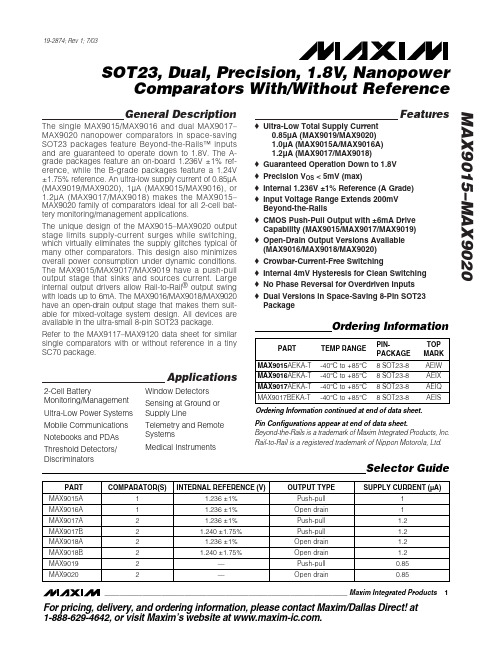
MAX9016AEKA-T MAX9017AEKA-T MAX9017BEKA-T
Ordering Information continued at end of data sheet. Pin Configurations appear at end of data sheet. Beyond-the-Rails is a trademark of Maxim Integrated Products, Inc. Rail-to-Rail is a registered trademark of Nippon Motorola, Ltd.
元器件交易网
19-2874; Rev 1; 7/03
SOT23, Dual, Precision, 1.8V, Nanopower Comparators With/Without Reference
General Description
The single MAX9015/MAX9016 and dual MAX9017– MAX9020 nanopower comparators in space-saving SOT23 packages feature Beyond-the-Rails™ inputs and are guaranteed to operate down to 1.8V. The Agrade packages feature an on-board 1.236V ±1% reference, while the B-grade packages feature a 1.24V ±1.75% reference. An ultra-low supply current of 0.85µA (MAX9019/MAX9020), 1µA (MAX9015/MAX9016), or 1.2µA (MAX9017/MAX9018) makes the MAX9015– MAX9020 faቤተ መጻሕፍቲ ባይዱily of comparators ideal for all 2-cell battery monitoring/management applications. The unique design of the MAX9015–MAX9020 output stage limits supply-current surges while switching, which virtually eliminates the supply glitches typical of many other comparators. This design also minimizes overall power consumption under dynamic conditions. The MAX9015/MAX9017/MAX9019 have a push-pull output stage that sinks and sources current. Large internal output drivers allow Rail-to-Rail® output swing with loads up to 6mA. The MAX9016/MAX9018/MAX9020 have an open-drain output stage that makes them suitable for mixed-voltage system design. All devices are available in the ultra-small 8-pin SOT23 package. Refer to the MAX9117–MAX9120 data sheet for similar single comparators with or without reference in a tiny SC70 package. o Ultra-Low Total Supply Current 0.85µA (MAX9019/MAX9020) 1.0µA (MAX9015A/MAX9016A) 1.2µA (MAX9017/MAX9018) o Guaranteed Operation Down to 1.8V o Precision VOS < 5mV (max) o Internal 1.236V ±1% Reference (A Grade) o Input Voltage Range Extends 200mV Beyond-the-Rails o CMOS Push-Pull Output with ±6mA Drive Capability (MAX9015/MAX9017/MAX9019) o Open-Drain Output Versions Available (MAX9016/MAX9018/MAX9020) o Crowbar-Current-Free Switching o Internal 4mV Hysteresis for Clean Switching o No Phase Reversal for Overdriven Inputs o Dual Versions in Space-Saving 8-Pin SOT23 Package
ZSPM9000Al1R中文资料(ZMDI)中文数据手册「EasyDatasheet - 矽搜」

KEMA 09ATEX0048 产品说明书

(13) SCHEDULE(14) to EC-Type Examination Certificate KEMA 09ATEX0048 Issue No. 4(15) DescriptionDifferential Pressure Transmitters DELTABAR M Model PMD55 and Pressure transmittersCERABAR M Model PMC51, Model PMP51 and Model PMP55 and DELTAPILOT M Model FMB50, Model FMB51, Model FMB52 and Model FMB53 are used in potentially explosive atmospheres caused by the presence of flammable gases, liquids, vapours or dusts for the measurement of level, flow, differential pressure, over- and under pressure.The pressure signal at the ceramic or metal sensor is converted into an electrical signal.The output of the Pressure or Differential Pressure Transmitter is a 4 - 20 mA current output signal with or without a superimposed HART digital signal, or the transmitter is intended to be connected to a fieldbus system (Profibus PA or Foundation Fieldbus).The several versions of the Pressure and Differential Pressure Transmitters differ in type of sensor, type of enclosure, process connection etc.Optionally all versions of the Pressure and Differential Pressure Transmitters may be provided with an indicator.Optionally, the display connector can be used for temporary connection of a service tool (e.g.Endress+Hauser Commubox type FXA191 or type FXA195).Optionally the Pressure Transmitters that are intended for application in explosive gas atmospheres, may be provided with a sensor with extension cable.Ambient temperature range -50 ºC to +70 ºC.The relation between temperature class, ambient temperature and process temperature is given in the following table.temperatureclassambienttemperatureprocess temperatureFMB50 FMB51 FMB52,FMB53PMD55 PMP55 1),PMC51, PMP51T6 ≤ 40 °C ≤ 80 °C ≤ 80 °C ≤ 80 °C ≤ 80 °C ≤ 80 °CT4 ≤ 70 °C ≤ 100 °C ≤ 85 °C ≤ 80 °C ≤ 120 °C ≤ 100 °C 2)T3 ≤ 70 °C ≤ 150 °CNOTE 1: Depending on the diaphragm seal used in model PMP55, a higher process temperature is permitted. For details, refer to the relevant equipment manual.NOTE 2: Process temperature for Models PMC51 and PMP51 with hygienic process connection ≤ 130 °C.. The maximum surface temperature of the enclosure T75 °C, respectively T500 100 °C (transmitters with interface 4 - 20 mA) or T500 105 °C (transmitters with Fieldbus interface) is b ased on the maximum ambient temperature of 70 °C for a dust lay er with a maximum thickness of 5 mm respectively 500 mm.(13) SCHEDULE(14) to EC-Type Examination Certificate KEMA 09ATEX0048 Issue No. 4Electrical dataTransmitters in type of protection intrinsic safety Ex iaInterface 4 - 20 mA (with or without HART communication):Supply and output circuit (terminals + and - or connector):in type of protection intrinsic safety Ex ia IIC, only for connection to a certified intrinsically safe circuit, with the following maximum values:U i = 30 V; I i = 300 mA; P i = 1 W; L i = 0 mH; C i = 10 nF.Interface Profibus PA or Foundation Fieldbus:Supply and data circuit (terminals + and - or connector):in type of protection intrinsic safety Ex ia IIC, only for connection to a certified intrinsically safecircuit, with the following maximum values:U i = 24 V; I i = 250 mA; P i = 1,2 W; L i = 10 µH; C i = 5 nF;or to an intrinsically safe fieldbus in accordance with FISCO, with the following maximum values: U i = 17,5 V; I i = 500 mA; P i = 5,5 W; L i = 10 µH; C i = 5 nF.Display connector:in type of protection intrinsic safety Ex ia IIC, for connection to a certified intrinsically safe circuit, with following maximum values:U o = 8,6 V; I o = 39 mA; P o = 124 mW andU i = 8,5 V; I i = 7 mA; P i = 10 mW; C i = 0 nF; L o = 0 mH.Transmitters in type of protection Ex tU max = 45 V (interface 4 - 20 mA), respectively 32 V (fieldbus interface).Installation instructionsThe instructions provided with the equipment shall be followed in detail to assure safe operation. (16) Test ReportNo. NL/KEM/ExTR09.0017/**.(17) Special conditions for safe useNone.(18) Essential Health and Safety RequirementsCovered by the standards listed at (9).(19) Test documentationAs listed in Test Report No. NL/KEM/ExTR09.0017/**.。
MAX889中文资料

MAX889
The MAX889 inverting charge pump delivers a regulated negative output voltage at loads of up to 200mA. The device operates with inputs from 2.7V to 5.5V to produce an adjustable, regulated output from -2.5V to -VIN. The MAX889 is available with an operating frequency of 2MHz (T version), 1MHz (S version), or 0.5MHz (R version). The higher switching frequency devices allow the use of smaller capacitors for space-limited applications. The lower frequency devices have lower quiescent current. The MAX889 also features a 0.1µA logic-controlled shutdown mode and is available in an 8-pin SO package. An evaluation kit, MAX889SEVKIT, is available.
元器件交易网
High-Frequency, Regulated, 200mA, Inverting Charge Pump MAX889
ABSOLUTE MAXIMUM RATINGS
IN to GND .................................................................-0.3V to +6V FB, SHDN, CAP+ to GND ............................-0.3V to (VIN + 0.3V) AGND to GND .......................................................-0.3V to +0.3V OUT to GND .............................................................-6V to +0.3V CAP- to GND ............................................(VOUT - 0.3V) to +0.3V Continuous Output Current ...............................................250mA Output Short-Circuit Duration ........................................Indefinite Continuous Power Dissipation (TA = +70°C) 8-Pin SO (derate 5.88mW/°C above +70°C)...............471mW Operating Temperature Range...........................-40°C to +85°C Junction Temperature ......................................................+150°C Storage Temperature Range .............................-65°C to +150°C Lead Temperature (soldering, 10s) ................................+300°C
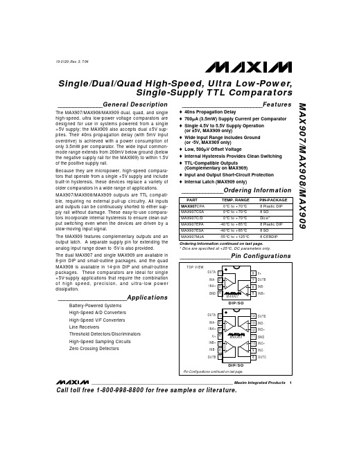
MAX908中文资料
元器件交易网ห้องสมุดไป่ตู้
MAX907/MAX908/MAX909
Single/Dual/Quad High-Speed, Ultra Low-Power, Single-Supply TTL Comparators
ABSOLUTE MAXIMUM RATINGS
Positive Supply Voltage (V+ to GND) . . . . . . . . . . . . . . . . . . . . . . . . +7V Negative Supply Voltage (V- to GND, MAX909 only) . . . . . . . . . -7V Differential Input Voltage
High-Speed Sampling Circuits
Zero Crossing Detectors
___________________________Features
o 40ns Propagation Delay o 700µA (3.5mW) Supply Current per Comparator o Single 4.5V to 5.5V Supply Operation
________________________________________________________________ Maxim Integrated Products 1
Call toll free 1-800-998-8800 for free samples or literature.
8 CERDIP
Ordering Information continued on last page. * Dice are specified at +25°C, DC parameters only.
蜚声功放MAX系列

※参数表3.24.25.2 7.2 12.28欧功率* 320W 450W 600W 850 W 1200W4欧功率* 500W 750W 1000W 1350W 2000W2欧功率** 650W 1200W 1350W 1700W 3000W输入灵敏度26dB/32dB/38dB电流放大模式AB 2H 2H 3H 3H总谐波失真(8欧1KHz 1/4输出功率)﹤0.03% ﹤0.03% ﹤0.05% ﹤0.08% ﹤0.08%阻尼系数(8欧1K) ﹥300 ﹥300 ﹥300 ﹥300 ﹥300转换速率20v/us 20v/us 20v/us 20v/us 20v/us输入阻抗(平衡/不平衡)20k/10k8欧时的电压增益36.0dB 37.2dB 38.4dB 41.2dB 42.3dB冷却方式由前往后面吹风方式输入输出连接方式和保护功能输入接口3-针卡隆母座/直通3-针卡隆公座输出接口红黑接线柱和Speakon座功放保护功能直流/短路/超温/过载/失真压限/高频啸叫/电源软启动尺寸和重量宽度483 483 483 483 483深度(连抽手)280 381 381 432 432高度2U 2U 2U 2U 2U净重9kg 11.5 kg 11.5 kg 13.5kg 13.5 kg功率值根据中国GB/T14200-1993、AES标准测量。
*采用1KHz连续正弦波在25摄氏度的自然通风环境下功放达到1%总谐波失真的时,在8欧、4欧、纯电阻负载上测量出的RMS均方根值电压换算得出。
**采用1KHz以40ms脉冲的正弦波在25摄氏度的自然通风环境下功放达到1%总谐波失真的时,在纯2欧电阻负载上测量出的RMS均方根值电压换算得出。
以上表格的参数数值均允许-2.5%·10%的误差,若参数有所变动,恕不另行通告。
※参数表4欧* 500W 700W 1050W 1350W 2000W2欧** N/A 1000W 1300W 1700W 2400W8欧* 920W 1350W 2100W 2750W 3900W4欧** N/A 1900W 2600W 3400W 4600W输入灵敏度26dB/32dB/38dB电流放大模式AB 2H 2H 3H 3H总谐波失真(8欧1KHz 1/4输出功率)﹤0.03% ﹤0.03% ﹤0.03% ﹤0.08% ﹤0.08%阻尼系数(8欧1K) ﹥100 ﹥100 ﹥180 ﹥250 ﹥330转换速率20v/us 20v/us 20v/us 25v/us 25v/us输入阻抗(平衡/不平衡)20k/10k8欧时的电压增益35dB 37dB 38dB 40dB 41dB冷却方式向后吹风设计输入输出连接方式和保护功能输入接口3-针卡隆母座/直通3-针卡隆公座输出接口红黑接线柱和Speakon座功放保护功能直流/短路/超温/过载/失真压限/高频啸叫/电源软启动尺寸和重量宽度483(19”) 483(19”) 483(19”)深度(连抽手)280(11”) 381(15”) 432(17”)高度89(3.5”)(2U) 89(3.5”)(2U) 89(3.5”)(2U)净重10.5kg 11.5 kg 11.5 kg 11.5kg 11.5 kg功率值根据中国GB/T14200-1993、AES标准测量。
马拉松MX系列发电机英文说明书

MAGNAMAXGENERATOR INSTALLATION OPERATION, AND MAINTENANCEMANUALTABLE OF CONTENTSTABLE OF CONTENTS (2)SAFETY (6)GENERAL INFORMATION (7)MECHANICAL DESIGN (7)General (7)Conduit Box (7)MagnaMAX Unirotor TM Construction (7)Adapters and Drive Discs (7)ELECTRICAL DESIGN (8)Temperature Rise (8)Standby Generator Ratings (8)Premium Insulation System (8)Power Factor (8)MagnaMAX Voltage Regulator (8)HOW TO READ A MODEL NUMBER (9)INSTALLATION (10)RECEIVING YOUR MAGNAMAX GENERATOR (10)UNPACKING AND HANDLING (10)STORAGE (10)PREPARATION FOR USE (10)GENERATOR MOUNTING - SINGLE BEARING (10)GENERATOR MOUNTING-TWO BEARING (11)BELT DRIVE (11)ENVIRONMENTAL CONCERNS (11)ELECTRICAL CONNECTIONS (12)GENERATOR LEAD CONNECTIONS (12)12 LEAD HIGH WYE CONNECTION (13)12 LEAD LOW WYE CONNECTION (13)12 LEAD HIGH DELTA CONNECTION (14)12 LEAD LOW DELTA CONNECTION (14)10 LEAD HIGH WYE CONNECTION (15)10 LEAD LOW WYE CONNECTION (15)6 LEAD WYE CONNECTION (16)6 LEAD DELTA CONNECTION (16)3 LEAD DELTA CONNECTION (17)4 LEAD WYE CONNECTION (17)DOUBLE DELTA -- SINGLE PHASE CONNECTION (18)LOW ZIG ZAG -- SINGLE PHASE CONNECTION (18)HIGH ZIG ZAG -- SINGLE PHASE CONNECTION (18)PARALLELING OPERATIONS (19)PRIME MOVER (19)VOLTAGE REGULATOR (19)SWITCHGEAR (19)PARALLELING BASICS (19)REACTIVE LOAD CONTROL (20)PARALLELING CIRCUITRY (20)THYRISTOR OR SCR LOADING (21)OPERATION (21)PRE-START INSPECTION (21)STARTING-UP THE GENERATOR (22)FIELD FLASHING (22)VOLTAGE ADJUSTMENTS (22)OTHER ADJUSTMENTS (23)MAINTENANCE (23)GENERAL INFORMATION (23)AIR INTAKE AND EXHAUST (23)ELECTRICAL CONNECTIONS, WINDINGS (24)LUBRICATION (24)DRYING ELECTRICAL INSULATION (26)Space Heaters (26)Oven (26)Forced Air (26)“Short Circuit” Method (26)CLEANING METHODS (27)Solvents (27)Cloth and Compressed Air (27)Brushing and Vacuum Cleaning (27)Shell Blasting (27)Steam Cleaning (27)DISASSEMBLY (28)REMOVAL FROM PRIME MOVER (28)CONDUIT BOX REMOVAL (29)EXCITER STATOR (FIELD) REMOVAL (30)EXCITER ARMATURE (ROTOR) REMOVAL (30)PMG STATOR REMOVAL (31)MAIN ROTOR REMOVAL (33)FRONT END BRACKET REMOVAL (35)EXCITER INSPECTION (35)EXCITER STATOR (35)EXCITER (ROTOR) ARMATURE (36)PMG INSPECTION (37)PMG STATOR (37)PMG ROTOR (37)MAIN ROTOR INSPECTION (37)BEARING (37)FAN (38)MAIN ROTOR CORE AND WINDINGS (40)DRIVE DISCS (SINGLE BEARING GENERATORS ONLY) (40)FRONT (EXCITER) END BRACKET INSPECTION (40)DRIVE END BRACKET OR SAE ADAPTER INSPECTION (41)MAIN STATOR INSPECTION (42)FRONT END BRACKET INSTALLATION (42)MAIN ROTOR INSTALLATION (42)PMG INSTALLATION (45)EXCITER INSTALLATION (46)CONDUIT BOX INSTALLATION (47)ASSEMBLY TO PRIME MOVER (48)TROUBLESHOOTING (50)INTRODUCTION (50)SYMPTOM: (51)NO VOLTAGE OR RESIDUAL VOLTAGE (51)LOW VOLTAGE - (52)NO LOAD (52)LOW VOLTAGE WHEN LOAD IS APPLIED (53)HIGH VOLTAGE (53)VOLTAGE IS FLUCTUATING (54)OPERATES SATISFACTORILY WHEN COLD, BUT SHUTS DOWN WHEN WARM (54)BUILDS VOLTAGE FROM STARTUP,THEN GOES TO LOW (RESIDUAL) VOLTAGE (54)EQUIPMENT RUNS NORMALLY ON UTILITY POWER, BUT WILL NOT RUN ON GENERATOR SET (54)GENERATOR TESTING (55)VISUAL INSPECTION (55)CONSTANT EXCITATION (12V BATTERY) TEST (55)MEASURING VOLTAGES (56)TYPICAL VOLTAGE MEASUREMENTS (57)Generator Output Voltage (57)Regulator Output (Exciter Stator Input) (57)Regulator Sensing (57)Regulator Input Volts (PMG Output Volts) (57)CURRENT (AMP) MEASUREMENTS (57)MEASURING RESISTANCE (58)Main Stator (58)Exciter Rotor (58)TESTING DIODES (RECTIFIERS) (58)INSULATION RESISTANCE - MAIN STATOR (59)GENERATOR TESTING (59)INSULATION RESISTANCE - MAIN ROTOR (59)INSULATION RESISTANCE - EXCITER STATOR (60)INSULATION RESISTANCE - EXCITER ROTOR (60)MAIN ROTOR FIELD AC IMPEDANCE TEST (60)MAGNAMAX EXPLODED VIEW (61)STANDARD TOOLS (64)SPECIAL TOOLS (65)MISCELLANEOUS (66)PREPARATION FOR SHIPMENT OR EXTENDED STORAGE (66)SHIPPING INSTRUCTIONS (66)STORAGE INSTRUCTIONS (66)TABLE 12-1: MAGNA MAX - FASTENER AND TORQUE SPECIFICATIONS (68)TABLE 12-2: CAPSCREW TORQUE VALUES (69)TABLE 12-3:EXCITATION DATA -60 HZ - 1800 RPM (70)TABLE 12-3:EXCITATION DATA -50 HZ - 1500 RPM (71)TABLE 12-5: RESISTANCE VALUES - MAIN WINDINGS (72)TABLE 12-6: RESISTANCE VALUES - EXCITER WINDINGS (73)SAFETYPLEASE REMEMBER SAFETY FIRST. If you are not sure of the instructions or procedures, seek qualified help before continuing.This service manual emphasizes the safety precautions necessary during the installation, opera-tion, and maintenance of your generator.Each section has caution and warning messages. These messages are for your safety and the safety of the equipment involved. If any of the cautions or warnings is not readily understood, seek clarification from qualified personnel before proceeding.Before any service work is done, disconnect all power sources and, where appropriate, lock out all controls, to prevent an unexpected start-up of the generator set. Proper grounding in compliance with local and national electrical codes must be provided. These safety precautions are necessary to prevent potential serious personal injury, or even death.The hazards associated with lifting or moving the generator are pointed out in the installation and service sections; incorrect lifting or moving can result in personal injury or property damage.Whenever the generator is running, always assume and proceed as if voltage is present. Residual voltage is present at the generator leads and at the regulator panel connections, even with the regulator fuse removed. Caution must be observed, or serious personal injury or death can result.Whenever solvents, cleaners, or flammable liquids are present, adequate ventilation must be available to avoid fire, explosion, and health hazards. Always avoid breathing vapors and use suitable personal protective equipment to prevent personal injuries. (Such as eyes, face, and hand protection.)This manual is not intended to be a substitute for properly trained personnel. Only qualified trained people should attempt repairs. The cautions and warnings point out known conditions that are potentially dangerous. Each installation will create its own set of circumstances. No manual can cover every possible situation.When in doubt, ask. Don’t be embarrassed to ask, “dumb questions”. Remember that dumb questions are much easier to handle than dumb mistakes.GENERAL INFORMATION MECHANICAL DESIGNGeneralAll single and two bearing units are manufactured with cast iron end brackets and adapters, and fabricated steel frames. Flexible drive discs and SAE adapters are machined to SAE standards. Pre-lubricated, regreasable, shielded ball bearings are used on MagnaMAX generators. Standard units are fully guarded. Drip proof shields are available as an option.Conduit BoxThe large end mounted conduit box is con-structed of formed sheet steel that will allow the addition of top mounted control packages. Refer to Marathon Electric for top mounted controls of more than 240 lbs. There is ample room inside the conduit box for a circuit breaker (through 800A Frame) and other options. The conduit box cover properly directs outside ventilating air through the generator.MagnaMAX Unirotor TM Construction An aluminum die cast rotor core affords high mechanical integrity and low vibration at operating speeds. Amortisseur winding and coil supports are die cast as an integral part of the rotor. Laminations are 4-pole, one piece laminations which are shrunk fit and keyed to the shaft. No dovetails, cross bolts or other pole to shaft connecting devices are used. The cast unidirectional aluminum alloy ventilation fan provides even air distribution to maximize cooling and generator efficiency.Adapters and Drive DiscsAll single bearing units are available with several adapters and drive disc arrangements. These can be shipped to order or can be changed in the field with standard shop tools. When changing flexible drive discs, spacers are used between the discs and the cast iron hub to maintain SAE standard dimensions.ELECTRICAL DESIGNAll standard products have 2/3 pitch main windings to eliminate the third harmonic. This serves to lower operating temperatures, give lower harmonic content and better waveform, and extend the overall life of the generator.Temperature RiseAll ratings and frame sizes are based on NEMA and CSA Class F and Class H temperature rises on both the rotor and stator windings. Ratings for British, German, French, IEC and all popular marine agencies are available.Standby Generator Ratings Synchronous generators used on emergency backup power can have temperature rises up to 25°C above those for continuous operation. (NEMA MG1 -22.40 and MG 1-22.84).Premium Insulation SystemAll MagnaMAX generators are built with Class H or better insulation materials. All standard generators are suitable for continuous duty at Class F temperature rise and will give equivalent or better winding life expectancy to generators supplied with Class A or B insulation systems operated within their temperature limits. The varnishes and epoxies used are synthetic, non-hygroscopic. Multiple dip and bake cycles of the main winding, plus a final coat of epoxy, make the standard winding moisture and fungus resistant. The MagnaMAX rotor is wet wound with thermo-setting epoxy applied between each layer, plus a final coating of epoxy for moisture and abrasion resistance. MagnaMAX generators can be ordered with an epoxy vacuum pressure impregnated insulation system as an option. (MagnaMAX generators with form wound coils include VPI as standard.)Power FactorAll standard generators are designed for operation at rated kVA at 0.8 lagging power factor but can be operated at rated kVA over the 0.8 to 1 .0 power factor range. MagnaMAX Voltage RegulatorThe standard voltage regulator is a fully encapsulated, static types with a solid state build up circuit. Standard features include 3-phase RMS sensing, paralleling, adjustable under frequency protection, and over excitation protection. The regulator meets EMI suppression to Mil Std-461B, part 9. An optional feature is adjustable armature current limiting. See the regulator manual for more information.HOW TO READ A MODEL NUMBERIt is extremely important to properly identify the machine when requesting parts or service. Always have the generator model number and serial number when requesting information from the factory. We cannot help you without this information.An Example For MagnaMAX Generators 431RSL 2000 AA - 000Character Category Description1st three characters Frame Number4th character Winding type R—Random WoundF—Form Wound5th character Bearing arrangement S—1 BearingD—2Bearings6th character Voltage range L—Up to 480 voltsM—1000-6600 voltsS—600 volts7th Character Product style4-Magna8th Character Type9th & 10th Character Wk2 Code11th Character Modification A-Z assigned sequentially 12th Character Mounting Arrangement A-Y see chart figurer 2-1 13th, 14th & 15th characters Modification numbers For internal use only Arrangement Adapter SAE Size Drive Disc SAE SizeA311-1/2B211-1/2C48D310E111-1/2F114G47-1/2H1DelcoJ1/214K210L1/2DelcoM014N2Small Delco0None NoneP018S0DelcoU0018V46-1/2W0021Y410Figure 2-1INSTALLATIONRECEIVING YOUR MAGNAMAX GENERATORUpon receipt of the generator, it is recommended that it be carefully examined for possible damage incurred in shipment. The generator was given to the Freight Company in good condition, and they are responsible for the product from our dock to yours. Any damage should be noted on the freight bill before accepting the shipment. Claims for damages must be promptly filed with the Freight Company. UNPACKING AND HANDLINGRead all instruction cards carefully. When lifting, attach an overhead crane to the lifting lugs on the generator frame. Apply lifting forces in a vertical direction.WARNINGTHE LIFTING LUGS ON THE GENERATOR ARE DESIGNED TO SUPPORT THE GENERATOR ONLY.DO NOT LIFT COMPLETE GENERATOR SET BY MEANS OF LIFTING DEVICES ON THE GENERATOR. PERSONAL INJURYOR QUIPMENT DAMAGE MAYOCCUR.STORAGEIn the event that the generator is not to be installed on the prime mover immediately, it is recommended that it be stored in a clean, dry area that is not subject to rapid changes in temperature and humidity. See "STORAGE INSTRUCTIONS" for more information.PREPARATION FOR USEAlthough the generator is carefully inspected and tested in operation before it leaves the factory, it is recommended the unit be thoroughly inspected. The insulation on the wire should be inspected and all bolts should be checked for tightness.Remove all shipping tapes, bags, blocks, and skids, which are used to prevent vibration and rotor movement during shipment. Dry, low-pressure compressed air of approximately 30 PSI (206 KPA) can be used to blow out the interior of the generator. In the case of two bearing machines, it is possible to turn the rotor by hand to make sure that it rotates smoothly without binding.If the machine has been in storage for a year or longer it is recommended that it be lubricated according to the lubrication instructions and chart supplied in the maintenance section.If the machine has been exposed to damp, humid conditions the insulation resistance should be checked. Refer to the instructions supplied in this manual.GENERATOR MOUNTING - SINGLE BEARINGSingle bearing generators are provided with an SAE flywheel adapter and flexible drive discs. Very close tolerances are maintained in the manufacture of the generator so that the alignment procedure is extremely simple. A coupling hub of nodular iron is shrunk on the shaft and special steel drivediscs are bolted to the hub. Holes are provided in the periphery of the coupling disc, which correspond to tapped holes inthe flywheel. The outside diameter of the discs fits in a rabbet in the flywheel so that concentricity is assured in all cases.WARNINGDO NOT APPLY ANY FORCE TO THE GENERATOR FAN FOR LIFITNG OR FOR ROTATING THE GENERATORROTOR. DISREGARDING THESEINSTRUCTIONS MAY CAUSE PERSONAL INJURY OR EQUIPMENTDAMAGECAUTION:GRADE 8 CAPSCREWSOR GRADE 8 PLACE-BOLTS AND HARDENED WASHERS ARE REC-OMMENDED TO MOUNT THE DRIVE DISCS TO THE FLYWHEEL.DO NOT USE HELICAL OR OTHER LOCKING DEVICES UNLESS APPROVED.The SAE adapter and the flywheel housing are designed to match each other with no further alignment necessary. Shims may be necessary under the feet of the generator to insure a solid mounting. See THE SERVICE SECTION for more information. GENERATOR MOUNTING-TWOBEARINGTwo bearing generators are provided with a shaft extension and key way. For direct-coupled sets the assembler furnishes a flexible coupling which is installed between the driver and the generator shaft.IMPORTANT: Aligning the two machinesas accurately as possible will reduce vibration, increase-bearing life, and insures minimum coupling wear. It may be necessary to shim the generator feet for proper support and alignment. Consult the coupling manufacturer’s instructions for alignment specifications and procedures. BELT DRIVEPlease refer to Marathon Electric for applications involving belt driven installations.ENVIRONMENTAL CONCERNSDirt, moisture, heat, and vibration are enemies of electrical equipment. The ambient temperature should not exceed the value shown on the generator nameplate. Generators for outdoor application should be protected from the elements by housings with proper openings for ventilation. This protection should be designed to prevent the direct contact of wind driven rain, snow, or dust with the generator. In moist or humid areas, such as the Tropics and marine serv-ice, additional protection is recommended. Although the standard windings are humidity and moisture resistant, special insulation and accessories such as space heaters can increase generator life. In extremely dirty and dusty environments a means of providing filtered cooling air to the generator is recommended. Please refer to Marathon Electric for filter kits that are available.ELECTRICAL CONNECTIONSThe generator conduit box construction allows conduit to enter the top, bottom, or either side of the box. A hole-saw or any suitable tool can be used to provide for the conduit entrance. Protect the interior of the generator from shavings when drilling or sawing. An approved connector must be used in conjunction with the conduit.To minimize the transmission of vibration, it is essential that flexible conduit be used for all electrical cable entrance to the generator. Refer to the connection diagram supplied with the generator and / or the proper diagrams shown in this section. Install all intercomponent and external wiring in accordance with the regulations of the national and local electrical codes. Clean all contact surfaces to assure good electrical bonding with the generator lugs or bus bars. Use heavy-duty terminal lugs or good quality clamps for making all connections. Insulate all connections in accordance with national and local regulations.Be sure the generator frame is grounded to all the other components of the system with a ground wire in accordance with national and local regulations.GENERATOR LEAD CONNECTIONS The electrical connections in the conduit box should be made in accordance with the appropriate “connection diagram.” Use the diagram appropriate for the number of leads and voltage range required. Refer to the drawings supplied with the generator and to drawings in this section.The final voltage setting is established within the selected range by an adjustment of the voltage regulator.CAUTION:SOME GENERATORS HAVE MULTIPLE, IDENTICALLY MARKED, CABLES FOR EACH LEAD. CONNECT ALL IDENTICALLY MARKED CABLES TOGETHER WHEN MAKING CONNECTIONS.PARALLELING OPERATIONSMagnaMAX generators come standard with amortisseur windings die cast as an integral part of the rotor. This exclusive, Unirotor TM, construction makes all MagnaMAX generators suitable for paralleling operations when the proper control equipment is added. Paralleling with other generator sets and / or with the utility power grid offers a number of advantages. Multiple unit installations increase power capacity; they can be added or removed from the line depending on the load requirements; they can be better maintained and repaired (since single source breakdown would mean total loss of power), and they often provide more reliable, efficient, and economical operation.Successful parallel operation means that the generators deliver power to the external system without delivering power to each other, or accepting power from the load bus or power grid. Additional equipment is necessary to insure safe and successful operation. PRIME MOVERThe prime mover provides the speed and torque which will be necessary to keep the machines in synchronized operation. A governor controls the prime mover's speed. The governor will directly control the watt or kW output and frequency of the unit. The governor must have special paralleling provisions to permit parallel operation with the other machines.VOLTAGE REGULATORThe voltage regulator controls the generator output voltage and the reactive power supplied by the generator. When two or more ac generators operate in parallel, the voltage regulator must have paralleling provisions (either internally or external to the regulator) to control the reactive or VAR load while it is in parallel operation. A separate paralleling current transformer is required to sense the reactive current and signal the voltage regulator. This additional paralleling circuitry is absolutely necessary to control the reactive current flowing between the generator sets. SWITCHGEARThere are additional relays and breaker controls that are necessary to insure safe, trouble free operation of paralleled units. Reverse power relays monitor the direction of power flow to insure that the generator is delivering power, not accepting it. These power relays control breakers, which are a means of connecting and disconnecting the gen-erator from the load. The total system can include over-voltage, over-current protection, under fre-quency protection, power factor correction provi-sion and a variety of associated control equipment from manual switchgear to microprocessors. The amount of control gear and level of sophistication will be determined by the needs and requirements of the particular application.PARALLELING BASICSThe following points are basic criteria which must be met before two units can be paralleled. THIS IS NOT MEANT TO BE SPECIFIC INSTRUCTIONS FOR PARALLELING OPERATION.1. Additional paralleling circuitryA. Voltage regulator-paralleling provisionsB.Paralleling current transformer(s)C. Paralleling provisions on governor controlsD. Switchgear2. The voltage and frequency must be the same for all sets with voltages in phase.3. The voltage regulation characteristics of the individual generators should be similar.4. The generators must have the same phase rotation.5.The driving engines should have the same speed regulation characteristics and the governors should be adjusted to give the same speed regulation.Before operating generator sets in parallel, each set should be checked by starting, operating, and adjusting the sets as individual units before attempting paralleling. REACTIVE LOAD CONTROLWhen two identical generators are operating together in parallel and an unbalance occurs in field excitation, circulating currents begin to flow between the generators. This current will appear as a lagging power factor or inductive load to the highly excited generator, and as a leading power factor or capacitive load to the generator with the lower field current. This is known as the reactive circulating current and there are two methods of controlling it in parallel operation:1. Reactive droop compensation. (Formerly known as parallel droop compensation.)The bus voltage droops, or decreases, as the reactive lagging power factor load is increased.2. Reactive differential compensation. (Formerly known as cross current compensation.) The reactive differential compensation circuit allows parallel generators to share reactive loads with no decrease or droop in generator voltage.The circuit must meet the following criteria:A.All paralleling current transformers for all the generators being paralleled must be included in the secondary interconnection loop.B. When different size generators are paralleled all paralleling current transformers must have the same proportional ratios that give approximately the same secondary current.C. Voltage regulator paralleling circuitry must be the same.D. Current transformer secondary and the generator lines must be isolated electrically.E. It is also desirable to have an auxiliary contact on the main generator breaker to short the parallel CT secondary when that breaker is open (not connected to the load bus).Because of the above criteria, reactive differential compensation cannot be used when paralleling with the utility power grid. There is no limit, however, in the number of generators that can be included in this type of circuit. PARALLELING CIRCUITRYBecause of the number of variables involved in paralleling generator sets, every installation will have its own circuitry and methods or procedure of bringing paralleled units on line. There are numerous ways of connecting paralleled units and an almost unlimited variety of applications and associated equipment.When parallel operation is desired, it is important that the control manufacturer, the generator manu-facturer, and the systems engineer work together to insure the proper selection of all components. Please refer to Marathon Electric for application assistance.THYRISTOR OR SCR LOADING Solid state electronic control devices which utilize thyristors or SCR firing circuits (such as variable frequency induction motor controls, precision motor speed controls, no-break powered battery chargers, etc.) can introduce high frequency harmonics which adversely affect or destroy the normal waveform of the generator. This creates additional heat in the generator stator and rotor, and can cause overheating. These devices can and do present problems to non-utility power generating equipment or any limited power bus system. The problems that can occur are not limited to the generator itself, but can effect the solid state control device, the equipment it controls, other associated loads, monitoring devices or a number of combinations over the entire system.MagnaMAX generators can supply power to thyristor or SCR loads when properly applied. The standard voltage regulator is PMG powered and senses 3 phase RMS voltages for maximum stability against severely distorted waveforms. SCR type applications such as cranes, shovels, etc., require special consideration of the generator insulation system due to greater dielectric stress and severe environmental conditions. It is impor-tant that the control manufacturer, the generator manufacturer, and the systems engineer work together to insure the proper selection of all components. Please refer to Marathon Electric for application assistance. OPERATIONPRE-START INSPECTIONBefore operating the generator for the first time, the following checks are recommended.1. A visual inspection should be made to check for any loose parts, connections, or foreign materials2. Check for clearance in the generator and exciter air gap. Be sure the generator set turns over freely. Bar the generator over by hand at least 2 revolutions to be sure there is no interference.WARNINGDO NOT APPLY ANY FORCE TO THEGENERATOR FAN FOR LIFITNG ORFOR ROTATING THE GENERATORROTOR. DISREGARDING THESEINSTRUCTIONS MAY CAUSE PERSONAL INJURY OR EQUIPMENTDAMAGE3. Check all wiring against the proper connection diagrams and make sure all connections are properly insulated. Support and tie leads to keep them from being damaged by rotating parts or by chafing on sharp corners.4. Be sure the equipment is properly grounded.5. Inspect for any remaining packing materials and remove any loose debris, building materials, rags, etc. that could be drawn into the generator.6. Check fasteners for tightness.7. Check to be sure no tools or other hardware have been left inside or near the machine.8. Install and check to be sure all covers and guards are in place and secure.WARNINGRESIDUAL VOLTAGE IS PRESENT AT THE GENERATOR LEADS AND AT THE REULATOR PANEL CONNECTIONS EVEN WITH THE REGULATOR FUSE REMOVED.CAUTION MUST BE OBSERVED OR SERIOUS PERSONAL INJURY OR DEATHCAN RESULT.STARTING-UP THE GENERATORThe following procedure should be followed for starting-up the generator for the first time:1.The generator output must be disconnected from the load. Be certain that the main circuit breaker is open.2.D isable the voltage regulator by removing the fuse.WARNINGDO NOT OVERSPEED THEGENERATOR. EXCESSIVE CENTRIFUGAL FORCES COULD DAMAGE THE ROTATING FIELDS. BE PREPARED FOR AN EMERGENCYSHUTDOWN.3.F ollow the manufacturer's instructions and start the prime mover. Check the speed and adjust to the RPM shown on the generator nameplate.4.Replace the regulator fuse and adjust the voltage to the required. Check all line to line and line to neutral voltages to be sure they are correct and balanced. If the voltages are not correct shut down immediately and recheck all connections.5. Close the main circuit breaker and apply the load.6. Monitor the generator output current to verify it is at or below nameplate amps.7. Adjust engine speed at full load to 1800 rpm for 60 hertz, 1500 rpm for 50 hertz. (Refer to prime mover/governor instruction manuals.)8. Before stopping the engine, remove the load by tripping the main circuit breaker.FIELD FLASHINGThe standard MagnaMAX generator is supplied with a PMG (permanent magnet generator). It will never require field flashing. In rare cases where a special generator may be furnished without a PMG, refer to the factory for more detailed information. Include the complete generator model and serial number.VOLTAGE ADJUSTMENTSThe voltage regulator controls the generator output voltage. There is a cover to access the controlpanel on the side of the generator conduit boxFigure 4-1Figure 4-2 Regulator Access Refer to the regulator manual for detailed information. In cases where special or remote mounted regulators are used, refer to instructions supplied by the generator set assembler and to the voltage regulator manual.。
常用集成芯片
常用芯片作用2007-07-30 16:40mc2831(mc2833)低功耗FM发射机mc3362低功耗FM接收机CXA1691BM收音机FM/AM接收芯片双音频编码器件是HM9187,解码芯片是MT8870(注意:HM9187输出的双音频信号幅值太大了,串联一个160K的电阻,送到M 幅度,幅度过高会导致窄带FM的调制/解调出问题.)ICL8038 单片集成压控波形发生器(应用广泛),在0.01~300kHz的范围里可以同时产生正弦波、矩形波和三角波。
使用时只作为压控振荡器、调频信号发生器或单片函数发生器。
其输出电平特性为:方波0.2V suppl y(2mA);三角波幅度为0.33V suppl y,输出阻22V supply,输出阻抗典型值为1kΩ。
MC145151 -2 锁相环芯片,是MC145151-1的性能改进产品,功耗降低而ESD和锁定性能则大有改进。
MC145151-2分别用N计数器和R计数器编程。
本器件集成了参考振荡器、可选参考频率分频器、数字相位鉴相器和14位可编程的除N计数器。
该芯工艺而具有低功耗,电压范围为3~9V;具有片上或离片参考振荡器的操作条件;有两路鉴相信号输出,其中PD out是鉴相器A的是鉴相误差信号,LD用来输出相位锁定信号;除N的范围为3~16383;8个用户可选的除R值分别为8、128、256、512、1应RA2~RA0从000到111的8个状态。
1.音频pcm编码DA转换芯片cirrus logic的cs4344,cs4334 。
4334是老封装,据说已经停产,4344封装比较小,非常好用2.音频放大芯片4558,LM833,5532,此二芯片都是双运放。
3.244和245,由于244是单向a=b的所以只是单向驱动。
而245是用于数据总线等双向驱动选择。
同时245的封装走线非常适4.373和374,地址锁存器,5.max232和max202,max3232 TTL电平转换6.网络接口变压器。
9018三极管数据手册
9018三极管数据手册1. 引言三极管是一种常见的电子元件,广泛应用于电子电路中的放大、开关和调节等功能。
而9018三极管是一款常用型号,具有优异的性能指标。
本文将详细介绍9018三极管的规格参数以及应用案例,帮助读者更好地了解和使用该元件。
2. 规格参数2.1 电气特性- 集电电流(IC):最大100mA- 输出功率(Pd):最大400mW- 电压放大倍数(hFE):80~300- 最大工作频率(ft):100MHz- 输入电阻(Rin):大于30kΩ2.2 封装形式- 封装形式:TO-92(3引脚)- 尺寸:5.16mm x 4.58mm x 4.58mm- 重量:不到1克2.3 温度特性- 工作温度范围:-55℃ ~ +150℃- 温度系数:-4mV/℃2.4 安装要求- 建议焊接温度:260℃(不超过10秒)- 建议焊接时间:3~5秒3. 电路应用3.1 放大电路9018三极管具有较高的电压放大倍数,适用于放大电路设计。
例如,在音频放大器电路中,9018三极管可用作阶级放大器的输出级,确保高质量的音频输出。
3.2 开关电路由于9018三极管具有较高的开关速度和较小的开启延迟时间,可用于开关电路。
在自动控制系统中,可将9018三极管作为控制信号的开关,实现电路的自动切换。
3.3 调节电路9018三极管的电流放大特性使其可用于电路调节。
例如,在电源稳压电路中,通过设计合适的负反馈回路,使用9018三极管实现电压稳定和调节。
4. 注意事项4.1 极性标记9018三极管的引脚有明确的极性,其中包括基极(B)、发射极(E)和集电极(C)。
在使用前,请确保正确连接元件,以避免不必要的损坏。
4.2 寿命和可靠性使用9018三极管时,应注意避免超过规定的最大工作电流和功率,以确保元件的寿命和可靠性。
4.3 温度控制9018三极管的工作温度范围较广,但请尽量避免超过150℃的高温环境,以免影响元件的性能和寿命。
MAX1978中文数据手册

用于Peltier模块的集成温度控制器概论MAX1978 / MAX1979是用于Peltier热电冷却器(TEC)模块的最小, 最安全, 最精确完整的单芯片温度控制器。
片上功率FET和热控制环路电路可最大限度地减少外部元件, 同时保持高效率。
可选择的500kHz / 1MHz开关频率和独特的纹波消除方案可优化元件尺寸和效率, 同时降低噪声。
内部MOSFET的开关速度经过优化, 可降低噪声和EMI。
超低漂移斩波放大器可保持±0.001°C的温度稳定性。
直接控制输出电流而不是电压, 以消除电流浪涌。
独立的加热和冷却电流和电压限制提供最高水平的TEC保护。
MAX1978采用单电源供电, 通过在两个同步降压调节器的输出之间偏置TEC, 提供双极性±3A输出。
真正的双极性操作控制温度, 在低负载电流下没有“死区”或其他非线性。
当设定点非常接近自然操作点时, 控制系统不会捕获, 其中仅需要少量的加热或冷却。
模拟控制信号精确设置TEC 电流。
MAX1979提供高达6A的单极性输出。
提供斩波稳定的仪表放大器和高精度积分放大器, 以创建比例积分(PI)或比例积分微分(PID)控制器。
仪表放大器可以连接外部NTC或PTC热敏电阻, 热电偶或半导体温度传感器。
提供模拟输出以监控TEC温度和电流。
此外, 单独的过热和欠温输出表明当TEC温度超出范围时。
片上电压基准为热敏电阻桥提供偏置。
MAX1978 / MAX1979采用薄型48引脚薄型QFN-EP 封装, 工作在-40°C至+ 85°C温度范围。
采用外露金属焊盘的耐热增强型QFN-EP封装可最大限度地降低工作结温。
评估套件可用于加速设计。
应用光纤激光模块典型工作电路出现在数据手册的最后。
WDM, DWDM激光二极管温度控制光纤网络设备EDFA光放大器电信光纤接口ATE特征♦尺寸最小, 最安全, 最精确完整的单芯片控制器♦片上功率MOSFET-无外部FET♦电路占用面积<0.93in2♦回路高度<3mm♦温度稳定性为0.001°C♦集成精密积分器和斩波稳定运算放大器♦精确, 独立的加热和冷却电流限制♦通过直接控制TEC电流消除浪涌♦可调节差分TEC电压限制♦低纹波和低噪声设计♦TEC电流监视器♦温度监控器♦过温和欠温警报♦双极性±3A输出电流(MAX1978)♦单极性+ 6A输出电流(MAX1979)订购信息* EP =裸焊盘。
MAX4080TASA+中文资料
元器件交易网
MAX4080/MAX4081
19-2562; Rev 0; 10/02
EVAALVUAAILTAIOBNLEKIT
76V, High-Side, Current-Sense Amplifiers with Voltage Output
General Description
General System/Board-Level Current Sensing
Precision High-Voltage Current Sources
Features
♦ Wide 4.5V to 76V Input Common-Mode Range ♦ Bidirectional or Unidirectional ISENSE ♦ Low-Cost, Compact, Current-Sense Solution ♦ Three Gain Versions Available
(MAX4081 Only)....-0.3V to the lesser of +18V or (VCC + 0.3V) Output Short Circuit to GND.......................................Continuous Differential Input Voltage (VRS+ - VRS-) ...............................±80V Current into Any Pin..........................................................±20mA
三极管90—9018参数
三极管90—9018参数1.最大封装功率(Pc):三极管的最大封装功率是指在特定工作温度下,可持续承受的最大功率。
对于9011-9018系列的三极管,其最大封装功率一般在0.625瓦到1瓦之间。
2.最大集电极电流(Ic):最大集电极电流是指三极管的集电极最大可承受的电流大小。
对于9011-9018系列的三极管,其最大集电极电流一般在0.5安到1安之间。
3. 最大集电极-基极(Vceo)和最大集电极-发射极(Vces)电压:最大集电极-基极电压和最大集电极-发射极电压分别表示三极管集电极与基极、集电极与发射极之间的最大可承受电压。
对于9011-9018系列的三极管,其最大集电极-基极电压和最大集电极-发射极电压一般在40伏到75伏之间。
4. 最大集电极-基极漏电流(Iceo)和最大集电极-发射极漏电流(Ices):最大集电极-基极漏电流和最大集电极-发射极漏电流分别表示三极管在关断状态下的最大漏电流。
对于9011-9018系列的三极管,其最大集电极-基极漏电流和最大集电极-发射极漏电流一般在50微安到100微安之间。
5. 最大漏极-源极电压(Vceo)和最大漏极-源极漏电流(Idss):对于一些型号的三极管,由于其属于场效应管的一种,因此存在漏极和源极之间的电压和漏电流。
最大漏极-源极电压和最大漏极-源极漏电流分别表示三极管漏极和源极之间的最大可承受电压和漏电流。
总结起来,三极管9011-9018系列的参数包括最大封装功率、最大集电极电流、最大集电极-基极电压、最大集电极-发射极电压、最大集电极-基极漏电流、最大集电极-发射极漏电流、最大漏极-源极电压和最大漏极-源极漏电流等。
这些参数是评估三极管性能和应用范围的重要指标,根据具体的应用需求,可以选择适合的型号。
马尔萨斯电子JCM900值 Series电钢吉他电铃机说明书

J C M 900V A L V E S E R I E SWARNING!PLEASE READ THE FOLLOWING LIST CAREFULLYA. ALWAYS fit a good quality mains plug conforming to the latestB.S.I. standards (UK only).B. ALWAYS wire the plug in accordance with the colour code attached to the mains lead (UK only).C. DO NOT attempt to remove the amplifier chassis. There are no user serviceable parts inside.D. ALWAYS have this equipment serviced or repaired by competent, qualified personnel.E. NEVER under any circumstances, operate the amplifier without an earth.F. NEVER use any amplifier in damp or wet conditions.G. ALWAYS ensure that the impedance of the amplifiers speaker orspeakers connected does not fall below the minimum impedance rating.I. PLEASE READ this instruction manual carefully before switching on.INTRODUCTIONMarshall have specialised in the production of valve amplification since 1962.The unique tone and playing response of the valve has formed the cornerstone of the Marshall “Sound of Rock”, which we have modified over the years to cope with the changing demands of the evolving guitar player.The JCM 900 models split into two distinct product ranges, the Master Volume SL-X and the Dual Reverb. Though they share common ancestry and have similar rear panel functions their applications are quite different.HI GAIN MASTER VOLUME SL-XThe latest innovation from our valve designers involves the use of an extra ECC83 pre-amp valve in the gain stage of the Master Volume SL-X models.This gives a gain soaked front end that is the most extreme yet produced by Marshall and is controlled by twin gain controls, the first (item 2), from 0-10, the second (item 3), from 10-20! Combinations of these two controls can take you from classic Marshall crunch in lower positions, to pure overdriven outrage onmaximum. It is well worth experimenting with these twin gains in conjunction with the tone network (items 6-9) to really get to know the full capability of your new SL-X head.The twin Master Volumes (items 4 & 5) are another unique feature of the SL-X amp giving you twofootswitchable output volume levels, ideal for rhythm to solo switching.Although a clean sound is available, this amp was designed for the uncompromising high gain player who demands a no compromise sound.HI GAIN DUAL REVERBThe Dual Reverb range was designed for versatility with two independently controlled footswitchablechannels, each voiced totally differently.Channel A is voiced for brilliant clean tones with the gain control (item 2) on lower settings and crunch to lower gain lead as you turn it up.Channel B is boosted with enough gain (item 3), for fearsome lead tones, ranging from classic on lower settings to contemporary screaming solos on maximum.Channel master volumes (items 9 & 11) and individual channel reverb controls (items 8 & 10) give you incredible control and all round versatility in either, head or combo form.VALVE OUTPUT POWERThe JCM 900 range use high quality 5881 output valves (x2 in 50 Watt models, x4 in 100 Watt models) for their unique distortion properties and fluid tone.With most valve amplifiers, particularly Marshalls', the best sounds are achieved when the Master Volumes are set high enough to be utilising the driving power of the output valves to the full.This delicate working balance between the pre-amp and power amp levels can only be achieved byexperimentation.You will find that all the JCM 900 models like to work hard and are designed to withstand prolonged use at full power quite readily. The PB100 Power attenuator is ideal for this use (connects between amp andcabinets) as it will allow you to run your amp at full power but keep the overall volume low.The important thing to remember here is that it is the interaction between all the controls that plays a part in achieving your sound.HI GAIN MASTER VOLUME 900 SL-XFRONT PANEL FUNCTIONSModels 2100 & 25001. Input JackConnects the instrument to the amplifier. (A high quality screened lead must be used).2. Pre-Amp Volume ControlSets the initial gain level of the pre-amp section (0-10). Lower settings for clean sounds - higher settings for crunch and overdrive.3. Gain Sensitivity ControlSets the secondary gain level of the pre-amp section (10-20).NOTE:Combinations of the two gain controls (items 2 and 3) provide a wide range of clean, crunch and overdrive possibilities. Experimentation will reveal the optimum settings for each.4 & 5. Master Volume “A” Master Volume “B”Twin footswitchable Master Volume Controls. Master “B” controls the overall volume exclusively when a footswitch is not connected. The connection of footswitch P801 allows switching between Master “A” or “B”giving independent volume levels for rhythm and solo playing.6,7,8 & 9. Treble, Middle, Bass & PresencePassive equalisation circuit. These controls are interactive to provide the maximum range of tonal variation.10. Master Volume B “ON” LED IndicatorIndicates red when Master Volume “B” is selected.11. Footswitch Jack SocketInput for the connection of remote footswitch (model P801).12. Standby SwitchControls the H.T. supply to the amplifier valves. Allows the filaments to remain heated during breaks.13. Power SwitchOn/Off switch for total mains power to the amplifier.HI GAIN DUAL REVERBFRONT PANEL FUNCTIONSModels 4100, 4101, 4102, 4500, 4501 & 45021. Input JackConnects the instrument to the amplifier. (A high quality screened lead must be used).2. Channel “A” Pre-Amp Gain ControlSets the gain level for channel “A”. Lower settings give clean sounds - higher settings for medium drive and crunch rhythm.3. Channel “B” Lead Gain ControlSets the gain level for boosted Channel B. Lower settings give slight overdrive - higher settings for maximum drive and sustain.4,5,6 & 7. Treble, Middle, Bass & PresencePassive rotary equalisation circuit. These interactive controls provide a wide range of tonal possibilities for both channels.8. Reverb Control Channel AControls the amount of reverb on Channel “A”.9. Master Volume Channel AControls the overall volume level of Channel “A”.10. Reverb Control Channel BControls the amount of reverb on Channel “B”.11. Master Volume Channel BControls the overall volume level of Channel “B”.12. Channel B ‘ON’ Push Switch/LEDIndicates red when Channel “B” is selected either manually or by remote footswitch (models P802).13. Footswitch Jack SocketConnects the remote dual footswitch (models P802) for reverb ON/OFF and Channel A/B switching.14. Standby SwitchAllows the amplifier to remain at “standby” (i.e. the valve heaters remain on, ready for instant use, but without the signal circuit being active).15. Power SwitchOn/Off switch for total mains power to the amplifier.REAR PANEL FUNCTIONS The Hi Gain Master Volume SL-X and DualReverb models feature comprehensive connection and control facilities on the rear panel which arecommon to both ranges.50 Watt Models 2500, 4500, 4501 & 45021. Effects Loop Level ControlAdjusts the level of the effects loop from -10dBVto + 4dBm. Higher settings match modern effectsprocessors and lower settings match floor pedals. NOTE:Some effects such as distortion and compressionare best suited to connection via the front panelinput as opposed to the loop.2. Effects Send SocketJack socket for connection to the input of external effects processor.3. Effects Return SocketJack socket for the connection from the output ofexternal effects processor.4. Recording Compensated Line-OutSocketJack socket for direct connection to recordingequipment or PA system. The signal is speciallyfiltered for optimum recording performance.5. Direct Line-Out SocketUnfiltered pre-amp signal for connection toexternal power amplifiers.6. Impedance Selector SwitchTwo-way switch for matching the amplifier tospeaker impedance. Amp heads feature 8 or 16Ohm operation. Combo versions feature 4 or 8Ohm options.7. Loudspeaker Output Jack SocketsParallel wired jacks for linking speaker cabinets.Ensure that the speaker system is easily capable of handling the full amplifier power and that theimpedance (item 6) is correctly selected. If in doubt consult your dealer.8. Output Mode SwitchSwitches the amplifier from high to low poweroutput. The “low” setting configures the outputstage to “triode” operation, which gives half therated output (i.e. 25 Watts on 50 Watts models - or50 Watts on 100 Watt models). The “high” powerposition gives “pentode” operation for the fullrated output.9. Valve Failure L.E.D.Indicates red when output valve fails and causesvalve fuse (item 10) to operate.10. Valve Failure FuseOperates in the event of an output valve failure and prevents any internal damage to the amplifier. NOTE:On 50 Watt models items 11 & 12 DO NOTappear.13. Mains Power InputConnects the amplifier to the mains power supply. NOTE:Always ensure that the incoming mains voltagematches that of the amplifier. If in doubt consultyour Marshall dealer.14. Mains Power FuseProtects the amplifier and mains supply in theevent of a fault.NOTE:Always ensure that the fuse value matches thelabelling on the amplifier rear panel. If in doubtconsult your dealer.REAR PANEL FUNCTIONS100 Watt models 2100, 4100, 4101 & 4102Items 1 to 8 follow the same format as the 50 Watt models.9 & 10. Valve Failure LED (OPV1-OPV4)Valve Fuse (OPV1-OPV4)In the case of output valve failure (OPV1-OPV4), the fuse (item 10) will operate and illuminate LED (item 9). The amplifier will continue to function on reduced power (Using OPV2-OPV3 Only). Service should be obtained as soon as possible to preventthe premature ageing of (OPV2-OPV3).11 & 12. Valve Failure LED (OPV2-OPV3)Valve Fuse (OPV2-OPV3)Similar functions to items (10) and (11) butoperating on OPV2 and OPV3.13. Mains Power InputConnects the amplifier to the mains power supply. NOTE:Always ensure that the incoming mains voltagematches that of the amplifier. If in doubt consultyour Marshall dealer.14. Mains Power FuseProtects the amplifier and mains supply in theevent of a fault.NOTE:Always ensure that the fuse value matches thelabelling on the amplifier rear panel. If in doubtconsult your dealer.JCM 900 SL-X HI GAIN MASTER VOLUMEFRONT PANEL。
Melexis发布一款新电流传感器 可以应对高达1000A的初级电流
Melexis 发布一款新电流传感器可以应对高达1000A
的初级电流
全球微电子工程企业迈来芯(Melexis)公司在其MLX91208 可编程霍尔效应(Hall-effect)电流传感器系列中又新增一款新器件,新发布的器件为高电流版本产品。
新产品MLX91208CAV 针对混合动力和电动汽车(HEV)等应用中的非常高磁场而优化,可以应对高达1000A 的初级电流。
该器件是对现有覆盖低磁场和高磁场功能的MLX91208 系列产品的有效补充。
由于采用了迈来芯专有的集成式磁选机(IMC)技术,符合AEC-Q100 要求的MLX91208 系列传感器可以准确地测量电流,但不需要常规霍尔效应电流传感器所必需的笨拙的外部铁磁磁芯。
创新的IMC 架构能够有效地使磁通量集中,从而提高了传感器的性能。
迈来芯公司的IMC-Hall®器件采用紧凑型表面贴装标准SOIC8 封装,从而可显着节省电路板空间,并简化组装过程。
这些传感器还具有很高的灵活性,能够通过相邻总线条(bus bars)、缆线或PCB 布线测量电流数据,并具有业界领先的精度和效率。
MLX91208CAV 器件是基于霍尔效应技术设计,可提供一个完整的高性
价比、非接触式电流检测机制,能够满足性能基准要求。
该器件还可提供许
多高电压应用要求的电气隔离(galvanic isolaTIon),同时消除了常见于其它旁路技术的附加功率损耗源。
440A-A09018中文资料
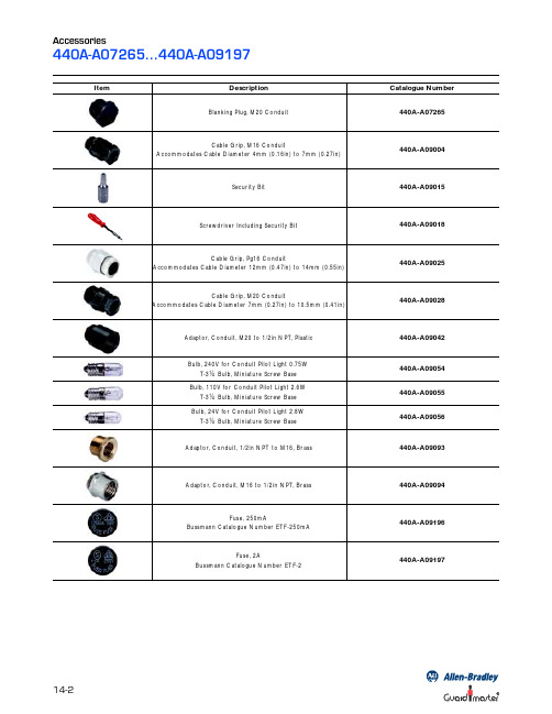
2 Mounting Holes for M5 Screws 12 (0.47) 56 (2.2)
Atlas Replacement End Cap
5 (0.2)
56 (2.2)
440G-A07180
14 (0.55)
52 (2.04) Ctrs M5
24 (0.94) 90 (3.54) 77 (3.03)
13.5 (0.53) 13 (0.51) 25 (0.98)
440K-A21030
19 (0.75)
3 (0.12)
Elf/Cadet Alignment Guide
13.5 (0.53) 13 (0.51) 25 (0.98) 18 (0.71) 13 51 (0.51)(2.01) 35 29 20.7 32.7 52.0 (2.04)
2 x M3
13 (0.51)
51 (2.01)
440G-A27143
4 x Ø5.5 (0.22) Ø10 20 (0.39) (0.78) 19 (0.74) 50 100 (3.93) 140 (5.51) 84 (3.3) 25.5 (1.0) 34 (1.33) 2.5 (0.09) 117.5 (4.62) 50 (1.96) 20
(Discard the Alignment Guide for GD2)
46.5 (1.83)
440K-A11144
20.7 (0.81) 3.5 (0.14)
15.5 (0.61) 14 (0.55)
Trojan T15 Standard Actuator (Standard model only)
Screw Pack (16 Security Screws M4 x 20mm & Bit)
MAX9814.pdf 麦克风放大器 用户手册说明书

General DescriptionThe MAX9814 is a low-cost, high-quality microphone amplifier with automatic gain control (AGC) and low-noise microphone bias. The device features a low-noise preamplifier, variable gain amplifier (VGA), output amplifier, microphone-bias-voltage generator, and AGC control circuitry.The low-noise preamplifier has a fixed 12dB gain, while the VGA gain automatically adjusts from 20dB to 0dB, depending on the output voltage and the AGC threshold. The output amplifier offers selectable gains of 8dB, 18dB, and 28dB. With no compression, the cascade of the amplifiers results in an overall gain of 40dB, 50dB, or 60dB. A trilevel digital input programs the output amplifier gain. An external resistive divider controls the AGC threshold and a single capacitor programs the attack/release times. A trilevel digital input programs the ratio of attack-to-release time. The hold time of the AGC is fixed at 30ms. The low-noise microphone-bias-voltage generator can bias most electret microphones.The MAX9814 is available in the space-saving, 14-pin TDFN package. This device is specified over the -40°C to +85°C extended temperature range.Applications●Digital Still Cameras ●Digital Video Cameras ●PDAs●Bluetooth Headsets●Entertainment Systems (e.g., Karaoke) ●Two-Way Communicators ●High-Quality Portable Recorders ●IP Phones/Telephone ConferencingFeatures●Automatic Gain Control (AGC)●Three Gain Settings (40dB, 50dB, 60dB) ●Programmable Attack Time●Programmable Attack and Release Ratio ● 2.7V to 5.5V Supply Voltage Range●Low Input-Referred Noise Density of 30nV/√Hz ●Low THD: 0.04% (typ) ●Low-Power Shutdown Mode●Internal Low-Noise Microphone Bias, 2V ●Available in the Space-Saving, 14-Pin TDFN(3mm x 3mm) Package ●-40°C to +85°C Extended Temperature Range19-0764; Rev 4; 2/20Ordering Information appears at end of data sheet.Microphone Amplifier with AGC and Low-Noise Microphone BiasMAX9814One Analog Way, Wilmington, MA 01887 U.S.A. | Tel: 781.329.4700 | © 2022 Analog Devices, Inc. All rights reserved.© 2022 Analog Devices, Inc. All rights reserved. Trademarks and registered trademarks are the property of their respective owners.Click here to ask an associate for production status of specific part numbers.V DD to GND ............................................................-0.3V to +6V All Other Pins to GND ..............................-0.3V to (V DD + 0.3V) Output Short-Circuit Duration ....................................Continuous Continuous Current (MICOUT, MICBIAS) ......................±100mA All Other Pins ...................................................................±20mA Continuous Power Dissipation (T A = +70°C)14-Pin TDFN-EP(derate 16.7mW/°C above +70°C) ........................1481.5mW Operating Temperature Range ...........................-40°C to +85°C Junction Temperature ......................................................+150°C Lead Temperature (soldering, 10s) .................................+300°C Bump Temperature (soldering) Reflow ............................+235°C(V DD = 3.3V, SHDN = V DD, C CT = 470nF, C CG = 2μF, GAIN = V DD, T A = T MIN to T MAX, unless otherwise specified. Typical values are at T A = +25°C.) (Note 1)PARAMETER SYMBOL CONDITIONS MIN TYP MAX UNITS GENERALOperating Voltage V DD Guaranteed by PSRR test 2.7 5.5V Supply Current I DD 3.16mA Shutdown Supply Current I SHDN0.011µA Input-Referred Noise Density e n BW = 20kHz, all gain settings30nV/√Hz Output Noise BW = 20kHz430µV RMSSignal-to-Noise Ratio SNR BW = 22Hz to 22kHz(500mV RMS output signal)61dB A-weighted64Dynamic Range DR(Note 2)60dBTotal Harmonic Distortion Plus Noise THD+Nf IN = 1kHz, BW = 20Hz to 20kHz,R L = 10kΩ, V TH = 1V (threshold = 2V P-P),V IN = 0.5mV RMS, V CT = 0V0.04%f IN = 1kHz, BW = 20Hz to 20kHz,R L = 10kΩ, V TH = 0.1V (threshold =200mV P-P), V IN = 30mV RMS, V CT = 2V0.2Amplifier Input BIAS V IN 1.14 1.23 1.32V Maximum Input Voltage V IN_MAX1% THD100mV P-P Input Impedance Z IN100kΩMaximum Gain A GAIN = V DD39.54040.5dB GAIN = GND49.55050.6GAIN = unconnected59.56060.5Minimum Gain GAIN = V DD18.72020.5dB GAIN = GND29.03030.8GAIN = unconnected38.74040.5Maximum Output Level V OUT_RMS1% THD+N, V TH = MICBIAS0.707V RMS Regulated Output Level AGC enabled, V TH = 0.7V 1.26 1.40 1.54V P-P AGC Attack Time t ATTACK C CT = 470nF (Note 3) 1.1msAttack/Release Ratio A/R A/R = GND1:500ms/ms A/R = V DD1:2000A/R = unconnected1:4000Low-Noise Microphone BiasAbsolute Maximum RatingsStresses beyond those listed under “Absolute Maximum Ratings” may cause permanent damage to the device. These are stress ratings only, and functional operation of the device at these or any other conditions beyond those indicated in the operational sections of the specifications is not implied. Exposure to absolute maximum rating conditions for extended periods may affect device reliability.Electrical Characteristics(V DD = 3.3V, SHDN = V DD , C CT = 470nF, C CG = 2μF, GAIN = V DD , T A = T MIN to T MAX , unless otherwise specified. Typical values are at T A = +25°C.) (Note 1)Note 1: Devices are production tested at T A = +25°C. Limits over temperature are guaranteed by design.Note 2: Dynamic range is calculated using the EIAJ method. The input is applied at -60dBFS (0.707μV RMS ), f IN = 1kHz.Note 3: Attack time measured as time from AGC trigger to gain reaching 90% of its final value.Note 4: CG is connected to an external DC voltage source, and adjusted until V MICOUT = 1.23V.Note 5: CG connected to GND with 2.2μF.PARAMETERSYMBOL CONDITIONSMINTYP MAXUNITS MICOUT High Output Voltage V OH I OUT sourcing 1mA 2.45V MICOUT Low Output Voltage V OLI OUT sinking 1mA 3mV MICOUT Bias MICOUT unconnected1.14 1.23 1.32V Output Impedance Z OUT 50ΩMinimum Resistive Load R LOAD_MIN 5kΩMaximum Capacitive Drive C LOAD_MAX 200pF Maximum Output Current I OUT_MAX1% THD, R L = 500Ω12mA Output Short-Circuit CurrentI SC38mAPower-Supply Rejection RatioPSRRAGC mode; V DD = 2.7V to 5.5V (Note 4)3550dBf = 217Hz, V RIPPLE = 100mV P-P (Note 5)55f = 1kHz, V RIPPLE = 100mV P-P (Note 5)52.5f = 10kHz, V RIPPLE = 100mV P-P (Note 5)43MICROPHONE BIAS Microphone Bias Voltage V MICBIAS I MICBIAS = 0.5mA 1.842.0 2.18V Output Resistance R MICBIASI MICBIAS = 1mA 1ΩOutput Noise Voltage V MICBIAS_NOISE I MICBIAS = 0.5mA, BW = 22Hz to 22kHz5.5µV RMSPower-Supply Rejection Ratio PSRRDC, V DD = 2.7V to 5.5V7080dBI MICBIAS = 0.5mA, V RIPPLE = 100mV P-P , f IN = 1kHz71TRILEVEL INPUTS (A/R, GAIN)Trilevel Input Leakage CurrentA/R or GAIN = V DD0.5V DD / 180kΩ0.5V DD / 100kΩ0.5V DD / 50kΩmAA/R or GAIN = GND0.5V DD / 180kΩ0.5V DD / 100kΩ0.5V DD / 50kΩInput High Voltage V IH V DD x 0.7V Input Low Voltage V IL V DD x 0.3V Shutdown Enable Time t ON 60ms Shutdown Disable Time t OFF40msDIGITAL INPUT (SHDN )SHDN Input Leakage Current -1+1µA Input High Voltage V IH 1.3V Input Low VoltageV IL0.5VAGC THRESHOLD INPUT (TH)TH Input Leakage Current-1+1µALow-Noise Microphone BiasElectrical Characteristics (continued)(V DD = 5V, C CT = 470nF, C CG = 2.2μF, V TH = V MICBIAS x 0.4, GAIN = V DD (40dB), AGC disabled, no load, R L = 10kΩ, C OUT = 1μF, T A = +25°C, unless otherwise noted.)POWER-SUPPLY REJECTION RATIOvs. FREQUENCYFREQUENCY (Hz)P S R R (d B )10k1k100-70-60-50-40-30-20-100-8010100kMICBIAS POWER-SUPPLY REJECTION RATIOvs. FREQUENCYFREQUENCY (Hz)P S R R (d B )10k1k100-100-90-80-70-60-50-40-30-11010100kSUPPLY CURRENT vs. SUPPLY VOLTAGEM A X 9814 t o c 04SUPPLY VOLTAGE (V)S U P P L Y C U R R E N T (m A )5.55.04.04.53.53.02.62.72.82.93.03.13.23.33.43.52.52.56.0SHUTDOWN CURRENT vs. SUPPLY VOLTAGEM A X 9814 t o c 05SUPPLY VOLTAGE (V)S H U T D O W N C U R R E N T (n A )5.55.04.54.03.53.00.10.20.30.40.502.5 6.0MICROPHONE BIAS VOLTAGEvs. MICROPHONE BIAS SOURCE CURRENTM A X 9814 t o c 06I MICBIAS (mA)V M I C B I A S V O L T A G E (V )2520151050.51.01.52.02.50030TOTAL HARMONIC DISTORTION PLUS NOISEvs. FREQUENCYFREQUENCY (Hz)T H D +N (%)10k1k1000.11100.0110100kGAIN vs. FREQUENCYFREQUENCY (Hz)G A I N (d B )10k1k1001020304050607080010100kTOTAL HARMONIC DISTORTION PLUS NOISEvs. OUTPUT VOLTAGEOUTPUT VOLTAGE (V RMS )T H D +N (%)1.00.50.11100.011.5INPUT-REFERRED NOISEvs. FREQUENCYFREQUENCY (kHz)I N P U T -R E F E R R E D N O I S E (µV R M S /H z )1010.1100100.0110010001Low-Noise Microphone BiasTypical Operating Characteristics(V DD = 5V, C CT = 470nF, C CG = 2.2μF, V TH = V MICBIAS x 0.4, GAIN = V DD (40dB), AGC disabled, no load, R L = 10kΩ, C OUT = 1μF, T A = +25°C, unless otherwise noted.)MICBIAS NOISE vs. FREQUENCYM A X 9814 t o c 10FREQUENCY (Hz)M I C B I A S N O I S E (nV R M S /H z )10k1k100100100010,0001010100kSMALL-SIGNAL PULSE RESPONSE200µs/divV MICIN 10mV/div0VV MICOUT 500mV/div0VC L = 10pFTURN-ON RESPONSEM A X 9814 t o c 1220µs/divV SHDN 5V/div 0V V MICBIAS 2V/div 0VV MICOUT 1V/div 0VV OUT vs. V INV IN (mV RMS )V O U T (V R M S )100500.250.500.751.0000150V OUT vs. V INV IN (mV RMS )V O U T (V R M S )3020100.250.500.751.000040V TH = 1VV TH = 0.75VV TH = 0.5VAGC ENABLED GAIN = 0V OUT vs. V INV IN (mV RMS )V O UT (V RM S )1050.250.500.751.000015ATTACK TIME200µs/divV MICOUT 500mV/div0VATTACK TIME200µs/divV MICOUT 500mV/div0VHOLD AND RELEASE TIME20ms/divV MICOUT 500mV/div0VLow-Noise Microphone BiasTypical Operating Characteristics (continued)(V DD = 5V, C CT = 470nF, C CG = 2.2μF, V TH = V MICBIAS x 0.4, GAIN = V DD (40dB), AGC disabled, no load, R L = 10kΩ, C OUT = 1μF, T A = +25°C, unless otherwise noted.)HOLD AND RELEASE TIME40ms/divV MICOUT 500mV/div C CT = 47nF A/R = V DD0VHOLD AND RELEASE TIME100ms/divV MICOUT 500mV/divC CT = 47nFA/R = UNCONNECTED 0VLow-Noise Microphone BiasTypical Operating Characteristics (continued)PIN NAME FUNCTIONTDFN 1CT Timing Capacitor Connection. Connect a capacitor to CT to control the Attack and Release times of the AGC.2SHDN Active-Low Shutdown Control3CG Amplifier DC Offset Adjust. Connect a 2.2µF capacitor to GND to ensure zero offset at the output.4, 11N.C.No Connection. Connect to GND.5V DD Power Supply. Bypass to GND with a 1µF capacitor.6MICOUT Amplifier Output 7GND Ground8MICINMicrophone Noninverting Input9A/RTrilevel Attack and Release Ratio Select. Controls the ratio of attack time to release time for the AGC circuit.A/R = GND: Attack/Release Ratio is 1:500A/R = V DD : Attack/Release Ratio is 1:2000A/R = Unconnected: Attack/Release Ratio is 1:400010GAINTrilevel Amplifier Gain Control.GAIN = V DD , gain set to 40dB.GAIN = GND, gain set to 50dB.GAIN = Unconnected, uncompressed gain set to 60dB.12BIAS Amplifier Bias. Bypass to GND with a 0.47µF capacitor.13MICBIAS Microphone Bias Output14TH AGC Threshold Control. TH voltage sets gain control threshold. Connect TH to MICBIAS to disable the AGC.—EPExposed Pad. Connect the TDFN EP to GND.MAX9814TDFNTOP VIEW245131110M I C B I A SN .C .G A I NS H D NN .C .V D D114+T HC T312B I A SC G69A /RM I C O U T78M I C I N G N D*EPLow-Noise Microphone BiasPin DescriptionPin ConfigurationDetailed DescriptionThe MAX9814 is a low-cost, high-quality microphone amplifier with automatic gain control (AGC) and a low-noise microphone bias. The MAX9814 consists of several distinct circuits: a low-noise preamplifier, a variable gain amplifier (VGA), an output amplifier, a microphone-bias-voltage generator, and AGC control circuitry.An internal microphone bias voltage generator provides a 2V bias that is suitable for most electret condenser microphones. The MAX9814 amplifies the input in three distinct stages. In the first stage, the input is buffered and amplified through the low-noise preamplifier with a gain of 12dB. The second stage consists of the VGA controlled by the AGC. The VGA/AGC combination is capable of varying the gain from 20dB to 0dB. The output amplifier is the final stage in which a fixed gain of 8dB, 18dB, 20dB is programmed through a single trilevel logic input. With no compression from the AGC, the MAX9814 is capable of providing 40dB, 50dB, or 60dB gain.Automatic Gain Control (AGC)A device without AGC experiences clipping at the output when too much gain is applied to the input. AGC prevents clipping at the output when too much gain is applied to the input, eliminating output clipping. Figure 1 shows a comparison of an over-gained microphone input with and without AGC.The MAX9814’s AGC controls the gain by first detecting that the output voltage has exceeded a preset limit. The microphone amplifier gain is then reduced with a select-able time constant to correct for the excessive output-voltage amplitude. This process is known as the attack time. When the output signal subsequently lowers in amplitude, the gain is held at the reduced state for a short period before slowly increasing to the normal value. This process is known as the hold and release time. The speed at which the amplifiers adjust to changing input signals is set by the external timing capacitor C CT and the voltage applied to A/R. The AGC threshold can be set by adjusting V TH . Gain reduction is a function of input signal ampli-tude with a maximum AGC attenuation of 20dB. Figure 2 shows the effect of an input burst exceeding the preset limit, output attack, hold and release times.If the attack-and-release times are configured to respond too fast, audible artifacts often described as “pumping” or “breathing” can occur as the gain is rapidly adjusted to follow the dynamics of the signal. For best results, adjust the time constant of the AGC to accommodate the source material. For applications in which music CDs are the main audio source, a 160μs attack time with an 80ms release time is recommended. Music applications typically require a shorter release time than voice or movie content.Figure 1. Microphone Input with and Without AGCMAX9814 AGC DISABLED400µs/div V MICIN 100mV/divV MICOUT(AC-COUPLED)1V/divMAX9814 fig01aMAX9814 AGC ENABLED400µs/divV MICIN 100mV/divV MICOUT(AC-COUPLED)1V/divMAX9814 fig01b0V0V0V0VLow-Noise Microphone BiasAttack TimeThe attack time is the time it takes for the AGC to reduce the gain after the input signal has exceeded the thresh-old level. The gain attenuation during the attack time is exponential, and defined as one-time constant. The time constant of the attack is given by 2400 x C CT seconds (where C CT is the external timing capacitor):● Use a short attack time for the AGC to react quickly to transient signals, such as snare drum beats (music) or gun shots (DVD).● Use a longer attack time to allow the AGC to ignore short-duration peaks and only reduce the gain when a noticeable increase in loudness occurs. Short-duration peaks are not reduced, but louder passages are. This allows the louder passages to be reduced in volume, thereby maximizing output dynamic range.Hold TimeHold time is the delay after the signal falls below the threshold level before the release phase is initiated. Hold time is internally set to 30ms and nonadjustable. The hold time is cancelled by any signal exceeding the set thresh-old level, and the attack time is reinitiated.Release TimeThe release time is how long it takes for the gain to return to its normal level after the output signal has fallen below the threshold level and 30ms hold time has expired. Release time is defined as release from a 20dB gain com-pression to 10% of the nominal gain setting after the input signal has fallen below the TH threshold and the 30ms hold time has expired. Release time is adjustable and has a minimum of 25ms. The release time is set by picking anattack time using C CT and setting the attack-to-release time ratio by configuring A/R, as shown in Table 1:● Use a small ratio to maximize the speed of the AGC.● Use a large ratio to maximize the sound quality and prevent repeated excursions above the threshold from being independently adjusted by the AGC.AGC Output ThresholdThe output threshold that activates AGC is adjustable through the use of an external resistive divider. Once the divider is set, AGC reduces the gain to match the output voltage to the voltage set at the TH input.Microphone BiasThe MAX9814 features an internal low-noise microphone bias voltage capable of driving most electret condenser microphones. The microphone bias is regulated at 2V to provide that the input signal to the low-noise preamplifier does not clip to ground.Applications InformationProgramming Attack-and-Release TimesAttack-and-release times are set by selecting the capacitance value between CT and GND, and by setting the logic state of A/R (Table 1). A/R is a trilevel logic input that sets the attack-to-release time ratio.The attack-and-release times can be selected by utilizing the corresponding capacitances listed in Table 2.Figure 2. Input Burst Exceeding AGC LimitTable 1. Attack-and-Release RatiosTable 2. Attack-and-Release TimeA/R ATTACK/RELEASE RATIOGND 1:500V DD 1:2000Unconnected1:4000C CT t ATTACK (ms)t RELEASE (ms)A/R = GND A/R = V DD A/R =UNCONNECTED22nF 0.052510020047nF 0.115522044068nF 0.1680320640100nF 0.24120480960220nF 0.5326510602120470nF 1.155022004400680nF 1.63815326065201µF2.412004800960010ms/divATTACKRELEASEHOLDLow-Noise Microphone BiasSetting the AGC ThresholdTo set the output-voltage threshold at which the microphone output is clamped, an external resistor-divider must be connected from MICBIAS to ground with the out-put of the resistor-divider applied to TH. The voltage V TH determines the peak output-voltage threshold at which the output becomes clamped. The maximum signal swing at the output is then limited to two times V TH and remains at that level until the amplitude of the input signal is reduced. T o disable AGC, connect TH to MICBIAS.Microphone Bias ResistorMICBIAS is capable of sourcing 20mA. Select a value for R MICBIAS that provides the desired bias current for the electret microphone. A value of 2.2kΩ is usually sufficient for a microphone of typical sensitivity. Consult the micro-phone data sheet for the recommended bias resistor.Bias CapacitorThe BIAS output of the MAX9814 is internally buffered and provides a low-noise bias. Bypass BIAS with a 470nF capacitor to ground.Input CapacitorThe input AC-coupling capacitor (C IN ) and the input resistance (R IN ) to the microphone amplifier form a high-pass filter that removes any DC bias from an input signal (see the Typical Application Circuit/Functional Diagram ). C IN prevents any DC components from the input-signal source from appearing at the amplifier outputs. The -3dB point of the highpass filter, assuming zero source imped-ance due to the input signal source, is given by:3dB_IN IN IN1f 2R C −=π××Choose C IN such that f -3dB_IN is well below the lowest frequency of interest. Setting f -3dB_IN too high affects the amplifier’s low-frequency response. Use capacitors with low-voltage coefficient dielectrics. Aluminum electrolytic, tantalum, or film dielectric capacitors are good choices for AC-coupling capacitors. Capacitors with high-voltage coefficients, such as ceramics (non-C0G dielectrics), can result in increased distortion at low frequencies.Output CapacitorThe output of the MAX9814 is biased at 1.23V. To eliminate the DC offset, an AC-coupling capacitor (C OUT ) must be used. Depending on the input resistance (R L ) of the following stage, C OUT and R L effectively form a high-pass filter. The -3dB point of the highpass filter, assuming zero output impedance, is given by:3dB_OUT L OUT1f 2R C −=π××ShutdownThe MAX9814 features a low-power shutdown mode. When SHDN goes low, the supply current drops to 0.01μA, the output enters a high-impedance state, and the bias current to the microphone is switched off. Driving SHDN high enables the amplifier. Do not leave SHDN unconnected.Power-Supply Bypassing and PCB LayoutBypass the power supply with a 0.1μF capacitor to ground. Reduce stray capacitance by minimizing trace lengths and place external components as close to the device as possible. Surface-mount components are recommended. In systems where analog and digital grounds are available, connect the MAX9814 to analog ground.Low-Noise Microphone BiasLow-Noise Microphone Bias+Denotes a lead(Pb)-free/RoHS-compliant package.T = Tape and reel.*EP = Exposed pad.PACKAGE TYPE PACKAGE CODE OUTLINE ND PATTERN NO.14 TDFN-EPT1433+221-013790-0062PARTTEMP RANGE PIN-PACKAGE MAX9814ETD+T-40°C to +85°C14 TDFN-EP*Low-Noise Microphone BiasChip InformationPROCESS: BiCMOSPackage InformationFor the latest package outline information and land patterns (footprints), go to /packages . Note that a “+”, “#”, or “-” in the package code indicates RoHS status only. Package drawings may show a different suffix character, but the drawing pertains to the package regardless of RoHS status.Ordering InformationREVISION NUMBERREVISION DATE DESCRIPTIONPAGES CHANGED03/07Initial release—12/09Updated Ordering Information , Absolute Maximum Ratings , Pin Description , and Pin Configuration sections to include EP for TDFN package 1, 2, 6, 1126/09Removed UCSP package1, 2, 6, 11, 1238/16Updated and moved Ordering Information and Package Information tables 1, 1242/20Updated Ordering Information12Low-Noise Microphone BiasRevision HistoryInformation furnished by Analog Devices is believed to be accurate and reliable. However, no responsibility is assumed by Analog Devices for its use, nor for any infringements of patents or other rights of third parties that may result from its use. Specifications subject to change without notice. No license is granted by implication or otherwise under any patent or patent rights of Analog Devices. Trademarks and registered trademarks are the property of their respective owners.。
9018芯片
9018芯片
9018芯片(AD9018)是美国安德鲁斯集团(Andrews)推出的一款高性能宽带射频放大器芯片。
该芯片采用SiGe HBT (硅锗混合双极晶体管)技术制造,工作频率范围从1MHz
到8GHz。
它具有低噪声系数、高增益、高线性度和宽带特性等优点,适用于无线通信、卫星通信、雷达系统、测量仪器等高频应用领域。
9018芯片的低噪声系数是其一大亮点,低至1.6dB,可有效提高信号接收灵敏度,提供更好的信号接收质量。
它的高增益特性为系统提供了更强的信号放大能力,有助于提高系统的通信距离和覆盖范围。
此外,9018芯片还具有良好的线性度,可以减少信号失真和交调产生,提高系统的传输质量。
其宽带特性使得该芯片在不同的频段内都能提供良好的性能,满足多种应用需求。
9018芯片的应用非常广泛。
在无线通信领域,它可以作为射频接收机的前置放大器,提高信号强度和质量,增加通信距离和稳定性。
在卫星通信系统中,9018芯片可以应用于发射机和接收机模块,提高信号的覆盖范围和通信质量。
在雷达系统中,它可以作为天线前端的低噪声放大器,提高雷达的探测和跟踪性能。
在测量仪器领域,9018芯片可用于频谱分析仪、信号发生器等测试仪器,提供高精度的信号放大和处理功能。
总之,9018芯片作为一款高性能宽带射频放大器芯片,具有低噪声系数、高增益、高线性度和宽带特性等优点,在无线通信、卫星通信、雷达系统、测量仪器等高频应用领域有着广泛
的应用前景。
它的出现将进一步推动高频通信技术的发展,提高系统性能和用户体验。
- 1、下载文档前请自行甄别文档内容的完整性,平台不提供额外的编辑、内容补充、找答案等附加服务。
- 2、"仅部分预览"的文档,不可在线预览部分如存在完整性等问题,可反馈申请退款(可完整预览的文档不适用该条件!)。
- 3、如文档侵犯您的权益,请联系客服反馈,我们会尽快为您处理(人工客服工作时间:9:00-18:30)。
MAX9018AEKARev. ARELIABILITY REPORTFORMAX9018AEKAPLASTIC ENCAPSULATED DEVICESSeptember 22, 2003MAXIM INTEGRATED PRODUCTS120 SAN GABRIEL DR.SUNNYVALE, CA 94086Written byReviewed byJim Pedicord Bryan J. Preeshl Quality Assurance Quality Assurance Reliability Lab Manager Executive DirectorConclusionThe MAX9018 successfully meets the quality and reliability standards required of all Maxim products. In addition, Maxim’s continuous reliability monitoring program ensures that all outgoing product will continue to meet Maxim’s quality and reliability standards.Table of ContentsI. ........Device Description V. ........Quality Assurance InformationII. ........Manufacturing Information VI. .......Reliability EvaluationIII. .......Packaging Information IV. .......Die Information.....AttachmentsI. Device DescriptionA. GeneralThe dual MAX9018 nanopower comparator in a space-saving SOT23 packages features Beyond-the-Rails™ inputs and is guaranteed to operate down to 1.8V. The A-grade packages feature an on-board 1.236V ±1% reference. An ultra-low supply current of 1.2µA makes the MAX9018 comparator ideal for all 2-cell batterymonitoring/management applications.The unique design of the MAX9018 output stage limits supply-current surges while switching, which virtuallyeliminates the supply glitches typical of many other comparators. This design also minimizes overall powerconsumption under dynamic conditions. The MAX9018 has an open-drain output stage that makes them suitable for mixed-voltage system design. The device is available in the ultra-small 8-pin SOT23 package.B. Absolute Maximum RatingsItem RatingSupply Voltage (VCC to VEE) 6VIN+, IN-, INA+, INB+, INA-, INB-, REF/INA-, REF (VEE - 0.3V) to (VCC + 0.3V)Output Voltage (OUT_) (VEE - 0.3V) to +6VOutput Current (REF, OUT_, REF/INA-) ±50mAOutput Short-Circuit Duration (REF, OUT_, REF/INA-) 10sOperating Temperature Range -40°C to +85°CStorage Temperature Range -65°C to +150°CJunction Temperature +150°CLead Temperature (soldering, 10s) +300°CContinuous Power Dissipation (TA = +70°C)8-Pin SOT23 727MwDerates above +70°C8-Pin SOT23 9.1mW/°CII. Manufacturing InformationA. Description/Function: SOT23, Dual, Precision, 1.8V, Nanopower Comparators With ReferenceB. Process: B8 (Standard 0.8 micron silicon gate CMOS)C. Number of Device Transistors: 349D. Fabrication Location: California, USAE. Assembly Location: Malaysia or ThailandF. Date of Initial Production: July, 2003III. Packaging InformationA. Package Type: 8-Pin SOT23B. Lead Frame: CopperC. Lead Finish: Solder PlateD. Die Attach: Non-Conductive EpoxyE. Bondwire: Gold (1.0 mil dia.)F. Mold Material: Epoxy with silica fillerG. Assembly Diagram: # 05-9000-0428H. Flammability Rating: Class UL94-V0I. Classification of Moisture Sensitivityper JEDEC standard JESD22-112: Level 1IV. Die InformationA. Dimensions: 24 x 80 milsB. Passivation: Si3N4/SiO2 (Silicon nitride/ Silicon dioxide)C. Interconnect: Aluminum/Si (Si = 1%)D. Backside Metallization: NoneE. Minimum Metal Width: 0.8 microns (as drawn)F. Minimum Metal Spacing: 0.8 microns (as drawn)G. Bondpad Dimensions: 5 mil. Sq.H. Isolation Dielectric: SiO2I. Die Separation Method: Wafer SawV. Quality Assurance InformationA. Quality Assurance Contacts: Jim Pedicord (Manager, Reliability Operations)Bryan Preeshl (Executive Director)Kenneth Huening (Vice President)B. Outgoing Inspection Level: 0.1% for all electrical parameters guaranteed by the Datasheet.0.1% For all Visual Defects.C. Observed Outgoing Defect Rate: < 50 ppmD. Sampling Plan: Mil-Std-105DVI. Reliability EvaluationA. Accelerated Life TestB.The results of the 135°C biased (static) life test are shown in Table 1. Using these results, the Failure Rate (λ) is calculated as follows:λ = 1 = 1.83 (Chi square value for MTTF upper limit)MTTFλ = 22.62 x 10⁻⁹λ = 22.62 F.I.T. (60% confidence level @ 25°C)This low failure rate represents data collected from Maxim’s reliability monitor program. In addition to routine production Burn-In, Maxim pulls a sample from every fabrication process three times per week and subjects it to an extended Burn-In prior to shipment to ensure its reliability. The reliability control level for each lot to be shipped as standard product is 59 F.I.T. at a 60% confidence level, which equates to 3 failures in an 80 piece sample. Maxim performs failure analysis on any lot that exceeds this reliability control level. Attached Burn-In Schematic (Spec. # 06-6200) shows the static Burn-In circuit. Maxim also performs quarterly 1000 hour life test monitors. This data is published in the Product Reliability Report (RR-1M).B. Moisture Resistance TestsMaxim pulls pressure pot samples from every assembly process three times per week. Each lot sample must meet an LTPD = 20 or less before shipment as standard product. Additionally, the industry standard 85°C/85%RH testing is done per generic device/package family once a quarter.C. E.S.D. and Latch-Up TestingThe CM90-1die type has been found to have all pins able to withstand a transient pulse of ±1000V, per Mil-Std-883 Method 3015 (reference attached ESD Test Circuit). Latch-Up testing has shown that this device withstands a current of ±250mA.Table 1Reliability Evaluation Test ResultsMAX9018AEKATEST ITEM TEST CONDITION FAILURE SAMPLE NUMBER OFIDENTIFICATION PACKAGE SIZE FAILURES Static Life Test (Note 1)Ta = 135°C DC Parameters 48 0Biased & functionalityTime = 192 hrs.Moisture Testing (Note 2)Pressure Pot Ta = 121°C DC Parameters SOT23 77 0P = 15 psi. & functionalityRH= 100%Time = 168hrs.85/85 Ta = 85°C DC Parameters 77 0RH = 85% & functionalityBiasedTime = 1000hrs.Mechanical Stress (Note 2)Temperature -65°C/150°C DC Parameters 77 0Cycle 1000 Cycles & functionalityMethod 1010Note 1: Life Test Data may represent plastic DIP qualification lots.Note 2: Generic Package/Process dataAttachment #1TABLE II. Pin combination to be tested. 1/ 2/1/ Table II is restated in narrative form in 3.4 below. 2/ No connects are not to be tested. 3/ Repeat pin combination I for each named Power supply and for ground (e.g., where V PS1 is V DD , V CC , V SS , V BB , GND, +V S, -V S , V REF , etc). 3.4 Pin combinations to be tested. a.Each pin individually connected to terminal A with respect to the device ground pin(s) connected to terminal B. All pins except the one being tested and the ground pin(s) shall be open. b. Each pin individually connected to terminal A with respect to each different set of a combination of all named power supply pins (e.g., V SS1, or V SS2 or V SS3 or V CC1, or V CC2) connected to terminal B. All pins except the one being tested and the power supply pin or set of pins shall be open.c.Each input and each output individually connected to terminal A with respect to a combination of all the other input and output pins connected to terminal B. All pins except the input or output pin being tested and the combination of all the other input and output pins shall be open.Terminal A (Each pin individually connected to terminal A with the other floating) Terminal B (The common combination of all like-named pins connected to terminal B) 1. All pins except V PS1 3/ All V PS1 pins 2. All input and output pinsAll other input-output pinsMil Std 883DMethod 3015.7Notice 8TERMINAL BTERMINAL APROBE(NOTE 6) R = 1.5k Ω C = 100pf。
