FC18简单操作说明
F-18学习手册
敌俺识别应答机用法:选择一个雷达目标,按I,若几乎无声就是敌机,出现“嘟”声就是友机。
附本人原创攻略一份F/A-18大黄蜂沙漠风暴行动推荐普屏使用鼠标的同志们请先到Opinion选项之中将操作模式由摇杆(joystick)改成鼠标(mouse)本文只介绍常用按键和战术,其余的按键请参考《F/A-18沙漠风暴行动飞行员手册》esc暂停p暂停Ctrl q退出任务Shift esc退出任务Ctrl n改变时间( 6h)Ctrl f加快四倍速度或归还原来速度。
Ctrl w 变为扭曲时间(12X速度)或归还原来时间。
不过有限定要帮求:飞机在有动力飞行,自动驾驶仪打开并调整为HSEL/BALT/RALT模式,飞机没有bingo fuelCtrl s截图控制方法鼠标控制方向,具体方向请自己体会。
加速- 减速Space 或 v 在地面上刹车(假如速度为零而你仍按着space/v,就会把车刹住,你假如想继续前进就再按一下space/v。
在指示灯处有提示后按h收回尾钩)Shift g 请帮求清场。
Shift t 请帮求起飞。
Shift o 询问任务完成情况。
Backspace 开车/加力。
Shift e 弹射跳伞。
(救命用!新手切记!)f 收放襟翼。
g 收放起落架。
(起落架和襟翼到了一定的高度和速度会自动收回,但在未收回前浪费的机动性和油料很让人心疼。
)L 着陆指示器(提前用t键选好机场),按下后即会出现一道横线和一道竖线,用竖线对准跑道,用横线对准机场前端,即可做到较完美的降落。
在开启无线电降落指导器之后,按Shift l得到语音指导。
i 敌俺识别应答机用法:选择一个雷达目标,按I,若几乎无声就是敌机,出现“嘟”声就是友机。
a 自动驾驶。
Shift a 改变自动驾驶状态: {(无)普通{#ATTH 高度保持包括这些 ----{#HSEL 机头方向保持,(会按照路径点走){#BALT 海拔高度保持 {#RALT 雷达高度(即距地面距离,在伊朗山地表现明显)保持 {#CPL 降落自动驾驶(不可以用于航母,提前应用T键选好机场)w 改变自动驾驶仪的目标点。
消防调试---FC18调试手册V02.0
FS18 火灾报警系统调试维护手册FS18火灾报警系统调试维护手册FD18 现场设备FC18火灾报警控制器(联动型)JB-TGZL-FC18R火灾报警控制器(联动型)版本:V02.0FS18 火灾报警系统调试维护手册西门子西伯乐斯电子有限公司保留此手册最终解释权。
任何单位和个人未经授权不得发布或者传播此手册内容。
本调试维护手册适用于西门子FS18火灾报警系统的调试和维护。
本手册中的常规条款也可在线或致电索取。
西门子西伯乐斯电子有限公司将尽力避免文中的印刷及图片错误,但并不对可能出现的疏忽承担责任。
文中提到的产品参数以及适用说明如有更新,恕不另行通知。
西门子西伯乐斯电子有限公司版权所有,Copyright © 2006-2009FS18 火灾报警系统调试维护手册目录1概述 (1)2安全 (3)2.1安全提示 (3)2.2安全操作规程 (3)3系统设计 (4)3.1FS18系统示意图 (4)3.2探测回路拓扑结构 (5)3.3隔离模块应用规则 (6)3.4负载因子计算 (8)3.5传输距离 ····································································································································错误!未定义书签。
FC18简单操作说明
火灾自动报警系统操作说明一、首先把消防控制中心的火灾自动报警主机电源开关合上,为系统提供正常的供电电源(相对应指示灯亮)。
二、用户级别1)本系统包含3个不同的用户级别(等级1是默认的任何人、等级2是保卫人员、等及3是调试人员)。
2)不同的用户等级有不同的权限和不同的界面,输入相对应等级的密码可登录不同级别的操作界面.三、如何登录1)按菜单键显示主菜单,选择登录选项按OK键,密码输入窗口弹出,键入相应的2/3级密码即可登录.四、如何退出1)系统自动退出:在没有任何操作的情况下,用户将在系统设定的登录时间过后自动退出到1级用户。
2)手动退出:按菜单键显示主菜单,选择登录选项下拉退出选项,按OK 键即可退出.五、状态类型1)报警主机包含了7种类型的状态:正常、火警/启动、故障、监管、屏蔽、测试/移动测试.六、火警事件处理1)按确认/消音键将蜂鸣器消音.2)找出火警发生地点,通知相关人员现场核实火情.3)真实火情:火情可控的情况下,现场人员利用就近灭火设施(灭火器、消火栓等)当场扑灭,处理完后按复位键。
如果火情很紧急,立即打电话报警,同时按下主机操作面板上的自动键(主机状态为手动模式下),进行一系列消防联动,疏散相关楼层人群,以免造成不必要的伤害。
4)虚假火情:相关人员现场检查报警范围内的情况,是否有大量灰尘或烟雾,情况正常,通知控制室人员对主机进行复位。
七、故障事件处理1)按确认/消音键将蜂鸣器消音。
2)通知维保人员处理。
八、监管事件处理1)按确认/消音键将蜂鸣器消音。
2)查看监管事件发生地点,根据实际情况判断是否要到现场进行处理。
九、启动/反馈事件处理1)按确认/消音键将蜂鸣器消音.2)查看启动/反馈发生地点根据实际情况判断是否要到现场进行处理。
十、实时事件查询1)按菜单键显示主菜单事件菜单显示,选择任意一种需要查询事件,然后按OK键,全部符合要求的事件将被显示在浏览窗口中。
十一、如何进行屏蔽(隔离)/开放1)当有建筑装修、设备损坏或失效时,需要对其进行屏蔽.当装修或替换完成后,需立即将其开放,使其恢复到正常状态(被屏蔽的设备不会在向控制器发送信息)。
FC18_操作手册
目录第一章系统简介JB-TGZL-FC18R系列控制器包括:-FC1860型火灾报警控制器(联动型)1. 特点-符合国家标准GB4717-2005《火灾报警控制器》和GB16806-2006《消防联动控制系统》。
-全中文Windows风格菜单操作,清晰直观。
-右键弹出菜单列出当前设备/事件可选操作项,操作更加方便快捷。
-超大存储空间,最多可记录10000条历史记录,运行中发生的各类事件可全部记入历史档案中。
-控制器在设定时间内无任何操作发生,同时无任何报警、联动、故障信息时,控制器自动转为屏幕保护状态,延长液晶屏的使用寿命;当有事件/操作发生时,液晶屏自动点亮,控制器自动显示所发生的事件,按照逻辑关系联动相应设备。
-控制器带有2路可编程输入/输出(输出:40mA@24VDC,可通过编程设置为总报警和总故障输出;输入:干接点)。
-控制器带有1路声光控制电路@24VDC)。
-控制器自带8路联动盘(每路输出:40mA@24VDC),用于重要设备的自动控制或手动操作。
-控制器最多可连接6个扩展联动盘。
-采用“组”编程方式,同用途的设备可分配到同一个“组”中进行编程,简化逻辑关系,节省编程时间。
-单台控制器最大容量2016点。
-网络总线(FC18-BUS),最远距离1000米,最多可接8台控制器。
-火灾显示盘FRT,FR18-BUS最远距离1000米,最多可接32台火灾显示盘。
-回路总线(FD18-BUS)为两总线无极性,建议使用Φ≥mm2的阻燃双绞线,传输距离环路可达2500米,支路可达1500米。
-控制器拥有三种用户界面,分别为:1级用户界面、2级用户界面、3级用户界面;在不同的用户界面下可进行不同的操作,用户级别由密码保护。
-接线端子均采用可插拔方式,每位端子上均有清晰标识,安装、调试、维修方便,快捷。
-自动生成探测回路/自动映射设备。
-可由控制器调整探测灵敏度,自动适应环境变化,使火灾报警可靠性大大提高。
西门子FC18R消防火灾控制器基本操作
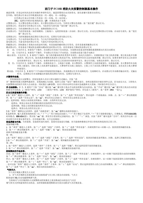
西门子FC18R消防火灾报警控制器基本操作液晶屏幕:在设定时间内没有任何操作和事件发生,液晶屏幕将自动关掉背光,按任意键可重新启动背光;打印机:绿色指示灯表示打印机通电状态(亮—通电,灭—未通电);红色指示灯表示打印机工作状态(亮—在线,灭—未在线);SEL:选择打印机在线/离线状态,LF:在离线状态下走纸火警指示灯:无火警信息指示灯熄灭,有火警信息指示灯点亮,当所有火警信息消除,按“复位键”指示灯灭;监管指示灯:有监管信号时指示灯点亮,当监管信号消失按“复位键”指示灯灭;故障指示灯:当有故障时指示灯点亮,故障消除指示灯灭;启动指示灯:当有控制设备(如控制模块,主板端口,远程控制设备)启动时,指示灯点亮;启动无反馈时指示灯闪烁;启动信号消失,按“复位键”指示灯灭;反馈指示灯:当控制器接收到反馈信号指示灯亮,反馈信号消失指示灯灭;主电指示灯:当主电供电时指示灯亮,当主电不供电时指示灯灭;备电指示灯:当备电供电时指示灯亮,当备电不供电时指示灯灭;屏蔽指示灯:控制器处于系统启动状态时闪烁;有设备被屏蔽时指示灯常亮,没有设备被屏蔽指示灯灭测试指示灯:有设备处于测试状态或移动测试状态时指示灯亮,没有设备处于测试状态指示灯灭自动:只允许在2、3级用户下操作,自动指示灯亮处于自动状态,全部联动设备由控制器依据逻辑联动关系自动联动手动:只允许在2、3级用户下操作,手动指示灯亮处于手动状态,全部联动设备只能手动执行确认/消音:只允许在2、3级用户下操作,按下消音键本机所有类型声音消失(备电欠压除外)。
在联机情况下按主机消音键,则主机从机声音都被消音,指示灯灭;按从机消音键则从机消音主机状态不变:如果有事件存在且没有按消音键,指示灯闪;如果有事件存在且已经消音没有新事件发生,指示灯灭;如果有事件存在且已经消音但有新事件发生,指示灯闪烁;如果没有事件,指示灯灭。
复位:只允许在2、3级用户下操作,在联机状态下,主机按下此键,非火警事件、火警事件主从机皆被复位;从机按此键,非火警事件在从机本机上被复位,同时主机上从机事件也被复位,火警事件在从机上被复位,主机上关于该从机火警事件不能复位,直至直至主机火警事件被复位。
百利达F1840体重秤使用说明
百利达F1840体重秤使用说明
1、选择你的个人编号,开机,当箭头所指位置闪动时,按上下键选择个人编号,再按SET键确定。
2、输入你的性别,当箭头所指位置闪动时,按上下键选择性别,再按SET键确定。
3、输入你的年龄,当箭头所指位置闪动时,按上下键选择年龄,再按SET键确定(可长按键来快速选择)
4、输入你的身高,当箭头所指位置闪动时,按上下键选择身高,再按SET键确定(可长按键来快速选择)
注意:输入参数时,请不要站在秤台上,当你的个人参数设定完后,然后显示:“0.0”KG(单位在KG状态),就可以称重和测量脂肪率。
FC18-操作手册

FC18-操作手册JB-TGZL-FC18R 型火灾报警控制器(联动型)操作说明书目录第一章 系统简介···········································································································································3 1. 特点 ·····················································································································································3 2. 性能参数················································································································································4 3. 外形尺寸················································································································································5 4. 兼容设备目录··········································································································································5 5. 系统结构················································································································································6第二章 安 装··············································································································································8 1. 安装过程················································································································································8 2. 接线图···················································································································································9 3. 拨码开关设置········································································································································13第三章 操 作·············································································································································14 1. 界面显示··············································································································································14 2. 液晶窗口显示········································································································································16 3. 用户级别··············································································································································18 3.1 登录 ··············································································································································19 3.2 退出 ··············································································································································19 4. 状态类型··············································································································································20 5. 火警事件处理········································································································································22 6. 故障事件处理········································································································································23 7. 监管事件处理········································································································································24 8. 启动/反馈事件处理·································································································································25 9. 实时事件查询········································································································································26 10. 设备属性查询········································································································································27 11. 历史记录查询········································································································································28 12. 如何进行屏蔽/开放·································································································································29 13. 如何进行启动/停止·································································································································30 14. 如何进行测试/移动测试···························································································································31 15. 如何进行定位测试/定位恢复·····················································································································32 16. 如何设置蜂鸣器音量·······························································································································33 17. 如何设置登录时间··································································································································34 18. 如何设置移动测试时间····························································································································35 19. 如何设置 LCD 关闭时间 ··························································································································36 20. 如何设置时间········································································································································37 21. 如何进行系统检测··································································································································38 22. 如何保存配置········································································································································39 23. 如何修改参数········································································································································40 24. 如何新建/查看联动关系···························································································································41 25. 如何编辑/删除联动关系···························································································································42 26. 如何进行组分配/FRT 分配 ·······················································································································44 27. 如何查看帮助信息··································································································································45 28. 如何操作联动盘·····································································································································45 29. 如何打开/关闭打印机······························································································································46 30. 如何替换设备········································································································································48页码:1/60。
FC18风扇控制器用户手册说明书
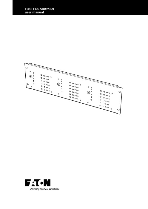
Contents1.INTRODUCTION (1)2.OVERVIEW (1)3.PC SOFTWARE OPERATION (SITE INSTALLER) (2)4.FAN CONTROLLER OPERATION (4)4.1 OPERATION PROCESS (4)4.1.1. MANUAL/AUTO KEY SWITCH (4)4.1.2. KEY SWITCH IN “MANUAL” (4)4.1.3. KEY SWITCH IN “AUTO” (4)4.1.4. FAULT MONITORING (4)4.1.5. RESET (4)4.1.6. TEST LED (4)5.BASIC SYSTEM LA YOUT (5)5.1. FC18 AND CFC301 ON SAME PANEL AND LOOP (5)5.2. FC18 AND CFC301 ON SAME PANEL BUT DIFFERENT LOOPS (5)5.3. FC18 AND CFC301 ON DIFFERENT NETWORKED PANELS (5)5.4. FC18 AND MCOM/MCIM ON SAME PANEL AND LOOP (5)5.5. FC18 AND MCOM/MCIM ON SAME PANEL BUT DIFFERENT LOOPS (6)5.6. FC18 AND MCOM/MCIM ON DIFFERENT NETWORKED PANELS (6)6.FC6 SPECIFICATION (7)6.1. ELECTRICAL SPECIFICATIONS (7)6.2. MECHANICAL SPECIFICATIONS (7)ii FC18 FAN CONTROLLER PR209-166-505-08January 2018 1FC18 Fan controller user manualFC18 FAN CONTROLLER 1.Introduction•The FC18 Fan Controller can be connected to a Cooper analogue addressable fire alarm control panel by means of the comms Loop utilizing only one address.•There are 6 channels per Fan Controller capable of controlling & indicating 6 individual Fans.•All FC18 Fan Controllers are programmed individually by means of the unique easy to use Cooper Site Installer PC software.•Each channel is programmed to an output device and feedback input device that can reside on any loop on any panel on the network to control & monitor the status of the Fan.•The CFC301 which takes 2 addresses on the loop,one for the control output which appears as a ZMU and one for the feedback input which appears as a technical input.•The MCIM can also be used as the feedback input.•The MCOM can also be used as the control output but is limited to 20 per loop.•The MCOM-S can also be used as the control output and is limited to 60 per loop but as it auto-learns and behaves like a sounder it will activate during an evacuation.•The MCOM-FC can also be used as the control output and is limited to 60 per loop but even though it auto-learns as a sounder it will not react to evacuations.Status LED•Power LED (Green) when Fan Control is working normally, the LED on•Fire Activation LED (Red) Operates when fire alarm is received from main panel Controls:Key switch •Auto/Manual key switch: used to select auto or manual control •Select Auto Mode: Green LED. The Fan Control operation is initiated by the state of the Fire Panel •Select Manual Mode: Red LED, The Fan Control operation is controlled by the “Stop/Start” buttons on the individual channels Reset button •Press the button to reset Fan Control. Reset from the main panel will not reset the fan controllerT est LED •Pressing the test LED button will start the control panelself-test Channel 1-6:Start/stop buttons•Start button: press the button, start one device.(Requires to start two channels of the one device)•Stop button: press the button to stop one device.(Requires to stop two channels of the one device)LED indication •ON LED (Red) Activated when the device receives feedback and the Start button has been pressed,otherwise, off.•Fault LED (Amber) Activated when No Feedback has been received after Start has been pressed or Stop button has been pressed but feedback has been received and/or Open Circuit/Short circuit has been reported, otherwise off.•OFF LED (Green) Activated when the stop button has been pressed and No Feedback has been received or no feedback is being received, otherwise off.2.OverviewPR209-166-505-08 January 20182FC18 FAN CONTROLLER 1.Start “Site Installer” program.Figure 1.2.Right click Fan Controller icon (Figure 2).Figure 2.3.Select “Edit Fan Controller” to go into the configuration screen.Figure 3.4.Once in the configuration screen Select “Add Master”.Figure 4.Figure 5.3.PC software operation (Site installer)PR209-166-505-08 January 20183FC18 Fan controller user manualFC18 FAN CONTROLLER 5.Select the output channel, one to six in the configuration screenSelect the “Enabled” in the configuration screen Select the “Loop Mode” in the configuration screen Select the “Confirm” in the configuration screenFigure 6. In the Panel, Loop and Address icons (drop down boxes) across from the Loop Mode, select where the control device you are going to use (CFC301 ZMU, MCOM,MCOM-S, MCOM-FC) is located on the system.In the Panel, Loop and Address icons (drop down boxes) across from the Confirm, select where the feedback device you are going to use (CFC301 Technical Input, MCIM) is located on the system. This only needs to beset if there is feedback from the fan itself.If you use 6 channels, you need to open the 6 channels which will allow you to write 6 rules.6.Select in the configuration screen which cause and effect is needed for the output to activate.Figure 7.GlobalBy addressBy zone groupSelect up to 3 stages to have a combination of different cause and effect results.Figure 8.PR209-166-505-08 January 20184.Fan controller operation 4.1. Operation process4.1.1. Manual/auto key switchA key switch is provided on the front of the Fan Controller to enable/disable the buttons on the front fascia. Thiskey switch must be kept secure and only accessible by authorised personnel who have been trained to use itor by the Fire Brigade. The purpose of this key switch is to prevent unauthorised activations of fans (i.e. by the general public).If the system enters a fire condition that effects the cause and effect rules of the fan controller while it is in manual mode it will not activate the fan control outputs but will remember the fire condition. Once the fan controlleris back in the auto mode it will activate the fan control outputs as per the fire condition and the cause and effect rules.4.1.2. Key switch in “manual”When the fan controller key switch is set in manual mode it enables the Start/Stop buttons for all 6 channels. The fan controller can be placed into manual mode even when the system is in a fire condition. This allows the Customer or the Fire Brigade to manually activate or deactivate the fan associated with each channel of the fan controller. Pressing the “Start” button will cause the control device for that channel to activate which will turn the fan on.If the fan has no feedback mechanism then the “On” LED will turn on automatically when the “Start” buttonis pressed. If the fan does have a feedback mechanism then the fan controller will expect to see the on signal from the feedback device within 25s. If the on signal is received within the time limit the “On” LED will turn on and the “Off” LED will turn off, but if the on signal isn’t received then the “Fault” LED will turn on. If the feedback signal arrives after the 25s it will result in the “Fault” LED to turn off, the “On” LED to be turned on and the “Off” LED to turn off to show the current status of the fan. Pressing the “Stop” button will cause the control device for that channel to deactivate which will turn the fan off. The fan controller expects to see the off signal from the feedback device within 25s. If the off signal is received within the time limit the “Off” LED will turn on and the “On” LED will turn off, but if the off signal isn’t received then the “Fault” LED will turn on. If the feedback signal arrives after the 25s it will result in the “Fault” LED to turn off, the “Off” LED to be turned on and the “On” LED to turn off to show the current status of the fan.4.1.3. Key switch in “auto”When the fan controller key switch is set in automatic mode it disables the Start/Stop buttons for all 6 channels will only allow the channels to be activated by the cause and effect programming of the Fire system.When the Fire system receives a fire alarm signal that effects the cause and effect rules of the Fan Controllerit will turn on the “Fire Activation” LED and activate the associated fan as if someone had pressed the start button for that channel (see manual Key Switch in “manual”for more details).4.1.4. Fault monitoringIf the fan controller receives a fault condition from either the control device or the feedback device (if the fan has feedback) it will result in the “Fault” LED turning on. This also includes short circuit and open circuit conditions between the feedback device and the fan itself.4.1.5. ResetA reset from any panel in the Fire system will not reset the Fan Controller itself but may result in the control and feedback devices being reset. This will require the Fan Controller to be manually reset using the “Reset” button. The key switch must be in the manual position in order for the reset button to work.Pressing the “Reset” button will reset the Fan Control back to its quiescent condition and all output devices will turn off.4.1.6. Test LEDPressing the “Test LED” button in auto or manualmode will cause all of the LEDs to flash 3 times and then return to showing the current state of the fan controller channels.PR209-166-505-08January 20184FC18 FAN CONTROLLER 5FC18 Fan controller user manualFC18 FAN CONTROLLER 5.Basic system layout5.1. FC 18 and CFC301 on same panel and loopFigure 9. 5.2. FC6 and CFC301 on same panel but di erent loopsFigure 10. 5.3. FC 18 and CFC301 on di erent n etworked panelsFigure 11.5.4. FC6 and MCOM/MCIM on same panel and loopFigure 12.PR209-166-505-08 January 20186FC18 FAN CONTROLLER FC18 Fan controller user manual5.5. FC 18 and MCOM/MCIM on same panel but di erent loopsFigure 13. 5.6. FC 18 and MCOM/MCIM on di erent networked p anelsFigure 14. PR209-166-505-08 January 20187FC18 Fan controller user manualFC18 FAN CONTROLLER 6.FC 18 6.1. ElectricalLoop load Minimum Nominal Maximum Quiescent current 310μA EnvironmentalOperating temperature -10°C +60°C Humidity (Non condensing)95%rh External 24 volt supply 18v 24v 28v External current 150mA CompatibilitySuitable for use with Cooper analogue addressable re systems 6.2. MechanicalPR209-166-505-08 January 2018Eaton is a registered trademark.All trademarks are property of their respective owners.Eaton EMEA Headquarters Route de la Longeraie 71110 Morges, Switzerland Eaton.euEaton Eaton Electrical Systems Ltd. Wheatley Hall Road Doncaster South Yorkshire DN2 4NB United Kingdom© 2017 Eaton All Rights Reserved Printed in UK Publication No. PR209-166-505-08 / CSSC-510 Article No.January 2018。
西门子FC18R消防火灾控制器基本操作
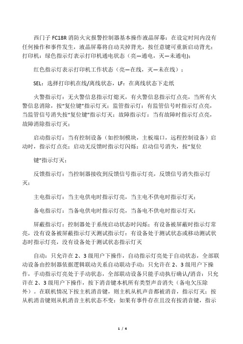
西门子FC18R消防火灾报警控制器基本操作液晶屏幕:在设定时间内没有任何操作和事件发生,液晶屏幕将自动关掉背光,按任意键可重新启动背光;打印机:绿色指示灯表示打印机通电状态(亮—通电,灭—未通电);红色指示灯表示打印机工作状态(亮—在线,灭—未在线);SEL:选择打印机在线/离线状态,LF:在离线状态下走纸火警指示灯:无火警信息指示灯熄灭,有火警信息指示灯点亮,当所有火警信息消除,按“复位键”指示灯灭;监管指示灯:有监管信号时指示灯点亮,当监管信号消失按“复位键”指示灯灭;故障指示灯:当有故障时指示灯点亮,故障消除指示灯灭;启动指示灯:当有控制设备(如控制模块,主板端口,远程控制设备)启动时,指示灯点亮;启动无反馈时指示灯闪烁;启动信号消失,按“复位键”指示灯灭;反馈指示灯:当控制器接收到反馈信号指示灯亮,反馈信号消失指示灯灭;主电指示灯:当主电供电时指示灯亮,当主电不供电时指示灯灭;备电指示灯:当备电供电时指示灯亮,当备电不供电时指示灯灭;屏蔽指示灯:控制器处于系统启动状态时闪烁;有设备被屏蔽时指示灯常亮,没有设备被屏蔽指示灯灭测试指示灯:有设备处于测试状态或移动测试状态时指示灯亮,没有设备处于测试状态指示灯灭自动:只允许在2、3级用户下操作,自动指示灯亮处于自动状态,全部联动设备由控制器依据逻辑联动关系自动联动手动:只允许在2、3级用户下操作,手动指示灯亮处于手动状态,全部联动设备只能手动执行确认/消音:只允许在2、3级用户下操作,按下消音键本机所有类型声音消失(备电欠压除外)。
在联机情况下按主机消音键,则主机从机声音都被消音,指示灯灭;按从机消音键则从机消音主机状态不变:如果有事件存在且没有按消音键,指示灯闪;如果有事件存在且已经消音没有新事件发生,指示灯灭;如果有事件存在且已经消音但有新事件发生,指示灯闪烁;如果没有事件,指示灯灭。
复位:只允许在2、3级用户下操作,在联机状态下,主机按下此键,非火警事件、火警事件主从机皆被复位;从机按此键,非火警事件在从机本机上被复位,同时主机上从机事件也被复位,火警事件在从机上被复位,主机上关于该从机火警事件不能复位,直至直至主机火警事件被复位。
FC 操作手册
JB-TGZL-FC18R型火灾报警控制器(联动型)操作说明书目录第一章系统简介 (3)1.特点 (3)2.性能参数 (4)3.外形尺寸 (5)4.兼容设备目录 (5)5.系统结构 (6)第二章安装 (8)1.安装过程 (8)2.接线图 (9)3.拨码开关设置 (13)第三章操作 (14)1.界面显示 (14)2.液晶窗口显示 (16)3.用户级别 (18)3.1登录 (19)3.2退出 (19)4.状态类型 (20)5.火警事件处理 (22)6.故障事件处理 (23)7.监管事件处理 (24)8.启动/反馈事件处理 (25)9.实时事件查询 (26)10.设备属性查询 (27)11.历史记录查询 (28)12.如何进行屏蔽/开放 (29)13.如何进行启动/停止 (30)14.如何进行测试/移动测试 (31)15.如何进行定位测试/定位恢复 (32)16.如何设置蜂鸣器音量 (33)17.如何设置登录时间 (34)18.如何设置移动测试时间 (35)19.如何设置LCD关闭时间 (36)20.如何设置时间 (37)21.如何进行系统检测 (38)22.如何保存配置 (39)23.如何修改参数 (40)24.如何新建/查看联动关系 (41)25.如何编辑/删除联动关系 (42)26.如何进行组分配/FRT分配 (44)27.如何查看帮助信息 (45)28.如何操作联动盘 (45)29.如何打开/关闭打印机 (46)30.如何替换设备 (48)页码:1/60JB-TGZL-FC18R型火灾报警控制器(联动型)操作说明书第四章维护 (49)1.日常检查 (49)2.应急故障处理 (49)3.可替代元件 (51)附录1 可编辑参数表 (52)附录2 设备可操作项一览表 (55)附录3 设备分组表 (57)附录4 联动关系编写规则 (58)附录5 输入法 (59)附录6 方便快捷的工程调试方法 (60)附录7 名词解释 (60)页码:2/60JB-TGZL-FC18R型火灾报警控制器(联动型)操作说明书第一章系统简介JB-TGZL-FC18R系列控制器包括:-FC1860型火灾报警控制器(联动型)1. 特点-符合国家标准GB4717-2005《火灾报警控制器》和GB16806-2006《消防联动控制系统》。
消防调试---FC18调试手册V02.0
消防调试---FC18调试⼿册V02.0FS18 ⽕灾报警系统调试维护⼿册FS18⽕灾报警系统调试维护⼿册FD18 现场设备FC18⽕灾报警控制器(联动型)JB-TGZL-FC18R⽕灾报警控制器(联动型)版本:V02.0FS18 ⽕灾报警系统调试维护⼿册西门⼦西伯乐斯电⼦有限公司保留此⼿册最终解释权。
任何单位和个⼈未经授权不得发布或者传播此⼿册内容。
本调试维护⼿册适⽤于西门⼦FS18⽕灾报警系统的调试和维护。
本⼿册中的常规条款也可在线或致电索取。
西门⼦西伯乐斯电⼦有限公司将尽⼒避免⽂中的印刷及图⽚错误,但并不对可能出现的疏忽承担责任。
⽂中提到的产品参数以及适⽤说明如有更新,恕不另⾏通知。
西门⼦西伯乐斯电⼦有限公司版权所有,Copyright ? 2006-2009FS18 ⽕灾报警系统调试维护⼿册⽬录1概述 (1)2安全 (2)2.1安全提⽰ (2)2.2安全操作规程 (2)3系统设计 (3)3.1FS18系统⽰意图 (3)3.2探测回路拓扑结构 (4)3.3隔离模块应⽤规则 (5)3.4负载因⼦计算 (7)3.5传输距离······························································································································································错误!未定义书签。
丰电一度驱动器说明书
一度高速门伺服控制器用户手册(数码版)YD660S序言感谢您采用我公司高性能、多功能门机专用伺服控制器。
本手册为使用者提供了安装、参数设定、故障诊断、排除及日常维护本控制器的相关注意事项及指导。
为了确保能够正确地安装及操作本控制器,请在装机之前详细阅读本使用手册,并妥善保存及交由该机器的使用者。
如对本控制器的使用存在疑难或有特殊要求,请随时联系本公司所在地区办事处或代理商,也可直接与本公司售后服务中心联系。
本手册适用于本公司生产的门机专用控制器系列产品,如有变动,恕不另行通知。
本手册版本20201221105以下各事项请使用者在使用本产品时特别留意请勿带电拔插,以避免发生意想不到的损坏。
试运行之前,请检查所有参数以确保机器不会发生意想不到的动作。
本人机界面上电源端口只能使用说明书上所规定的电压,以防止烧损或者不能正常工作。
连接本人机界面时如发现电源端端子或排线端子难以连接上时,请勿用力挤压并检查端子的朝向是否正确。
避免安装在阳光直射的地方或有振动的场所。
必须置于通风、无尘埃、干燥之处,避免放置于地面上,应置于合适的台架上且若周围环境恶劣,则应在包装袋中放置干燥剂。
储存位置的环境温度必须在 -20℃ - 40℃范围内;储存位置的相对四度必须在 0% - 90%范围内,且无结露;避免储存于含有腐蚀性气、液体的环境中。
目录第一章概况 (2)1.1 控制器的综合技术特性 (2)第二章接线 (2)2.1 接线端子图 (3)2.2标准接线图 (4)2.3 端子说明 (6)第三章操作 (7)3.1 数码管操作面板说明 (7)3.2 操作流程 (8)3.3 运行状态 (9)第四章快速调试 (10)4.1 限位学习操作 (10)第五章功能参数表 (12)第六章故障检查与排除 (20)6.1 故障信息及排除方法 (20)6.2 常见故障及其处理方法 (22)第一章概况1.1 控制器的综合技术特性●输入输出特性◆输入电压范围: 220V±15%◆输入频率范围:47~63Hz◆输出电压范围:0~额定输入电压◆输出频率范围:0~400Hz●外围接口特性◆开关量输入:9 路输入◆通讯接口:1路RS-485外部高速通讯 1路编码器高速通讯接口◆开路集电极输出:1路输出(互锁输出)◆继电器输出:3 路输出(1路刹车输出 2路功能继电器)◆电源:24V、12V直流DC输出最大提供1A电流输出●技术性能特性◆过载能力:150% 额定电流60s;200%额定电流15s●功能特性◆频率设定方式:数字设定。
F-18操作说明

Jane's F/A-18操作说明F1:Fwd cockpit view 座舱视角(可自由看)F2:Padlock center 前方视角F3:Padlock threat 观察威胁我的敌方目标F4:Padlock designtd 观察被我锁定的目标F5:Zoom left MDI 左多功能显示仪F6:Zoom right MDI 右多功能显示仪F7:Tactical cam 战术视角F8:Fixed chase 固定追逐视角F9:(Views)Player weapons 观察玩家的导弹F10:(Views)Wingman 观察僚机F11:(Views)Static grnd objs 观察最近的地面目标F12:(Views)Unlimited cam 任意视角~:AGARM prog 轮流武器程序(是武器投放数量)1:Cycle wpn 轮流武器2:Guns 机炮3:AIM-9 近距空空导弹4:AIM-7 中距空空导弹5:AIM-120 中距空空导弹6:Wpn step 武器步骤(导弹否决)7:Wide ACQ 宽阔捕获模式8:Boresit ACQ 孔径捕获模式9:Vertical ACQ 垂直捕获模式0:Auto ACQ 自动捕获模式-:Throttle dn 油门减小=:Throttle up 油门增加\:Afterburner 开加力BackSpace:Undes target 取消目标锁定TAB:W/F:radio menu 打开无线电菜单Q:Refuel probe 打开加油管W:Next waypnt 下一个导航点E:EMCON 电子反对策R:Radar silent 雷达到备用状态T:Tailhoook 放着舰钩Y:G limit ovrrde 显示过载报告U:Cage/uncage 隔离环/取消隔离环(空空模式中速度矢量保持在中央,真实飞行轨迹用速度矢量残影表示——自注)I:IFF inter 打开敌我识别装置O:HARM ovrrde HARM强制(有威胁时从任何选择的武器自动返回HARM模式——自注)P:Pause 暂停[:Cycle steering 轮流操作模式]:Cycle TDC 在各个DDI之间轮流分配TDCCAPS:LASER on/off 打开激光瞄准仪A:Autopilot 自动驾驶S:Speedbrake 刹车D:Dump fuel 放弃副油箱F:Flaps 放襟翼G:Landing gear 放起落架H:HUD color 改变HUD颜色J:Jammer 电子干扰K:Anti-col lights 飞机灯光开/关L:ILS on/off 仪表降落系统开/关;:Pri msn target 主要任务目标':Next msn tgt 下一个任务目标ENTER:Designate target 锁定目标Z:Zoom radar 缩小雷达范围X:Expand radar 增大雷达范围C:Caution disply 主警告显示V:Destrcto-cam 改变镜头B:Whl brks/cat 起落架刹车/网络呼叫N:Navflir 巡航模式M:Master mode 轮流主模式,:Left rudder 方向舵向左.:Right rudder 方向舵向右/:TDC joystick 允许TDC的摇杆控制SPACEBAR:Weapon pickle 发射武器Del 箔条Ins 曳光弹End ALE-50发射器PgDn 时间减少PdUp 时间加速Home 开始CMDS程序Num * 虚拟MPD交互作用上下左右允许摇杆控制TDC前提下,CAM移动ctrl+F10:(Views)WATCH_TANKERS 观察坦克ctrl+F11:(Views)WATCH_VEHICLES 观察车辆ctrl+1:Radio 第1通信频道(僚机,中队控制)ctrl+2:Radio 第2通信频道(预警机)ctrl+W:Atk air def 中队攻击空中目标ctrl+E:Engage air 中队空中接战ctrl+Y:Atk any gnd 中队攻击地面目标ctrl+I:Wpn check 中队检查武器ctrl+P:Req picture 预警机提供空情图像(2号通信)ctrl+A:Atk my tgt 僚机攻击我的目标ctrl+S:Status 中队报告状态ctrl+D:Bogie dope 预警机空情报告(1号通信)ctrl+G:Atk pri grnd 中队攻击首要地面目标ctrl+H:Help me 僚机提供援助ctrl+C:Call Clara 僚机掩护ctrl+V:Cover me 僚机掩护我ctrl+B:Call ball 请求火力支援(呼叫肉球——航母降落时有此程序)ctrl+M:Msg hist tggle 显示以前的消息(需要开启欺骗模式)SHIFT+F1:Fwd no cockpit 驾驶员座舱视点(不显示座舱)SHIFT+F2:Popup IFLOLSSHIFT+F3:VR ckpt lift line 虚拟座舱视角SHIFT+F4:Padlock packageSHIFT+F5:Zoom UFC UFCD缩放SHIFT+F6:Zoom MPCD MPCD缩放SHIFT+F7:Rev tactical cam 转动战术镜头SHIFT+F8:Floating chase 不固定尾追视角SHIFT+F9:Threat weapon 观察来袭导弹SHIFT+F10:Friendly aircraft 观察友机(每次按为下一架友机)SHIFT+F11:Enemy aircraft 观察敌机SHIFT+F12:Flyby 由固定视点观察我机SHIFT+1:Master arm 主武器开关状态开启SHIFT+2:Gun rate 机炮速率SHIFT+8:Radar ant up 雷达天线向上SHIFT+9:Radar ant rst 雷达天线复位SHIFT+0:Radar ant dn 雷达天线向下SHIFT+-:Throttle idle 油门空转SHIFT+=:Throttle mil 军用推力SHIFT+TAB:radio menu 无线电菜单SHIFT+W:Prev waypnt 前一个导航点SHIFT+E:Eject 弹射逃生SHIFT+R:Right eng 开关右引擎SHIFT+A:Jettison all 投弃所有外挂SHIFT+S:Jettison sel 投弃空对地武器SHIFT+K:Formation lts 编队灯开/关SHIFT+L:Left eng 开关左引擎SHIFT+':Prev msn tgt 前一个任务目标SHIFT+B: Tggle IFLOLSALT+F1:Vol explosions 爆炸效果改变ALT+F2:Vol clouds 云层效果ALT+F3:Terrain text 地形纹理ALT+F4:Terrain trans 地形过渡ALT+F5:Terrain dist 地形距离ALT+F6:Sprklng water 水面闪光ALT+F7:Roads 显示地面道路ALT+F8:Shadows 阴影效果ALT+F9:Obj number 物体数量ALT+F10:Object detail 物体细节ALT+F11:Canopy reflctALT+F12:Point lightsALT+-:Dec pan speedALT+=:Inc pan speedALT+\:O:VR ckpt det 虚拟座舱细节ALT+BS:O:Show wpns 显示飞机上的武器ALT+R:Rearm 补充弹药ALT+A:O:Air labels 空中物体标签ALT+S:Screen capt 抓图ALT+F:Auto-refuel 自动空中加油ALT+G:O:Grnd labels地面物体标签ALT+J:Center jystck 矫正摇杆附录:摇杆按钮分配(号码为按钮编号)1、机炮;2、武器释放;3、主模式轮流;4、武器轮流;5、颠倒视窗;6、锁定物体视窗;7、中队空中接战;8、中队攻击地面主要目标。
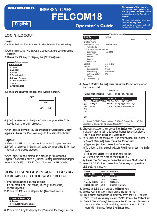
INMARSAT-C MES FELCOM18 操作指南说明书
1. Prepare message on the screen.For e-mail , set [Text Mode] in the [Editor Setup] menu to [Ascii].2. Press the F3 key to display the [Transmit] menu.3. Press the 1 key to display the [Transmit Message] menu.LoginConfirm that the terminal unit is idle then do the following:1. Confirm that [SYNC (NCS)] appears at the bottom of the screen.2. Press the F7 key to display the [Options] menu.3. Press the 2 key to display the [Login] screen.4. [Yes] is selected in the [Start] window; press the Enter key to start the login process.When login is completed, the message “Successful Login”appears. Press the Esc key to go to the standby display.HOW TO SEND A MESSAGE TO A STA-TION SAVED TO THE STATION LISTLogout1. Press the F7 and 3 keys to display the [Logout] screen.2. [Yes] is selected in the [Start] window; press the Enter key to start the logout process.When logout is completed, the message "SuccessfulLogout." appears and the [Current State] indication changes from [LOGOUT] to [IDLE]. Then, turn off the FELCOM.4. Select [Station Name] then press the Enter key to open the Station List.5. Choose a station then press the Enter key. To select multiple stations (simultaneous transmission), select a station and then press the Spacebar.6. For e-mail do the following. For other types, go to step7. 1) Select [Subject] then press the Enter key. 2) Type subject then press the Enter key.3) To attach a file, select [Attach File] then press the Enter key.4) Press the Enter key to open the file list. 5) Select a file then press the Enter key.6) Press the Esc key to close the window. Go to step 7. 7. Select [LES ID] then press theEnter key to open the LES setting window.8. Select an LES then press the Enter key9. Select [Confirmation] then press the Enter key.10. To request notification of delivery from the LES, select [ON]. If not necessary select [OFF]. Press the Enter key.11. Select [Send Delay] then press the Enter key. To send a message after a certain delay, enter a time up to 23 hours 59 minutes. Press the Enter key.LOGIN, LOGOUTWhen a life-endangering situation arises on your vessel, send the distress alert as shown below.1. If you have time to specify the nature of distress do steps 1) to 15) below. If not, go to step2.1) Press the F9 key to display the [Distress Alert Setup] screen.2) [LES ID] is selected; press the Enter key.3) Select a suitable LES then press the Enter key. 4) Select [Update Time] then press the Enter key. 5) Enter the current time then press the Enter key. 6) Select [Position] then press the Enter key.7) Enter your current position in latitude and longitude then press the Enter key.8) Select [Nature] then press the Enter key.9) Enter applicable nature of distress then press the Enter key.10) Select [Course] then press the Enter key. 11) Enter your course then press the Enter key. 12) Select [Speed] then press the Enter key. 13) Enter your speed then press the Enter key.14) Press the Esc key to show the [Update] window. 15) [Yes] is selected; press the Enter key to finish.2. Open the cover of the DISTRESS button on the Terminal Unit IC-218 or the Distress Alert Unit/Received Call UnitIC-305.12. Select [Delivery Delay] then press the Enter key.Select [Immediate] or [Deferred] then press the Enter key.13. Select [Code] then press the Enter key.14. Select [IA5] then press the Enter key.15. Put the cursor on [TRANSMIT] then press the Enter key to show the [Start] window.16. Press the Enter key to send the message to the message queue.17. Long-press the Esc key to return to the standby display.If the message was sent successfully, "Successful Sending message" appears and the TX message is printed (if [Confirmation] is OFF).How to cancel transmission on a message awaiting transmissionPress the F3 and 2 keys to show the [Cancel] screen.Select the message to cancel then press the Enter key.Press the Enter key again to cancel the message.3. Press the DISTRESS button until (approx four seconds) the lamp in the button lights continuously. The distress alert will not be sent until the lamp in the button lights continuously and the audio alarm sounds. The message "Sending Distress Alert" appears on the screen while thedistress alert is being sent.Terminal Unit IC-218button1. Press the F5 and 1 keys to show the [Data Report] menu.2. Press the appropriate numeric key to select a data report.3. Press the Enter key to open the status options window.4. Select appropriate option then press the Enter key. OFF : Data report offON : Enhanced Data Report (Data report w/confirmation) ON : Usual Data Report (Standard data report)5. Select [Report Length] then press the Enter key.6. Select appropriate option then press the Enter key. Position only : Own positionPosition and Course/Speed : Position, course and speed Position and Course/Speed with SEA INF : Position, course, speed, water temperature, tide, and depth 7. Select [DNID] then press the Enter key.8. Select DNID desired then press the Enter key.9. Select [LES ID] then press the Enter key.10. Select LES ID desired then press the Enter key.11. Select [Member No.] then press the Enter key.12. Select Member No. desired then press the Enter key.13. Select [Activation] then press the Enter key.14. Select [Regular Interval] then press the Enter key.15. Select [Interval Time] then press the Enter key.16. Key in interval time then press theEnter key.17. Select [Report Times] then press the Enter key.18. Key in the report times, or press the BackSpace key to display “---” to select [No Limit] to transmit data until the Status setting is turned OFF. Press the Enter key. 19. Press the Enter key to close the window.HOW TO SEND THE DISTRESS ALERT HOW TO SEND A DATA REPORT ATREGULAR INTERVALS PUB. NO. OSE-56740-A(1206, DAMI) FELCOM18。
FC18
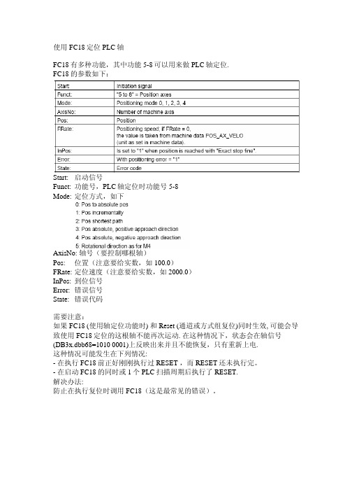
使用FC18定位PLC轴FC18有多种功能,其中功能5-8可以用来做PLC轴定位.FC18的参数如下:Start: 启动信号Funct: 功能号,PLC轴定位时功能号5-8Mode: 定位方式,如下AxisNo: 轴号(要控制哪根轴)Pos: 位置(注意要给实数,如100.0)FRate: 定位速度(注意要给实数,如2000.0)InPos: 到位信号Error: 错误信号State: 错误代码需要注意:如果 FC18 (使用轴定位功能时) 和Reset (通道或方式组复位)同时生效, 可能会导致使用FC18定位的这根轴不能再次运动. 在这种情况下,状态会在轴信号(DB3x.dbb68=1010 0001)上反映出来并且不能恢复,只有重新上电.这种情况可能发生在下列情况:- 在执行FC18前正好刚刚执行过RESET ,而RESET还未执行完。
- 在启动FC18的同时或1个PLC扫描周期后执行了RESET.解决办法:防止在执行复位时调用FC18(这是最常见的错误)。
实例:A I 3.7 // 复位键FP M150.0 // 读取上升沿S M150.1 // 设置通道正在进行复位标志A db21.dbx35.7 // 通道1处于复位状态FP M150.2 // 读取上升沿R M150.1A I7.5 // FC18的条件,此处用用户定义键模拟AN M150.1 // 通道没有正在复位S M150.3 // 启动FC18CALL FC18Start: M150.3 // 启动FC18Stop: False // 此处Stop信号无用Funct: b#16#5 // 功能5, PLC轴定位Mode: b#16#1 // 增量方式定位AxisNo: 1 // FC18控制轴1定位Pos: 10.0 // 增量走10mmFRate: 2000.0 // 速度是2000mm/minInPos : M150.4 // 到位信号Error : M150.5 // 错误信号State: MB152 // 错误代码O M150.4O M150.5O I3.7R M150.4。
Eaton FC18 Assembly Installer指南说明书
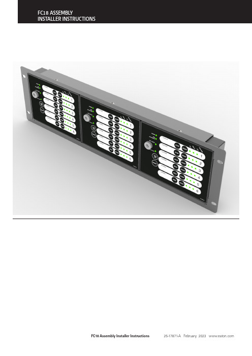
FC18 Assembly Installer Instructions25-17871-A February 2023 Contents Introduction Instructions SpecificationElectrical Specifications Mechanical Specifications 9 9 3 4 9FC18 Assembly Installer Instructions25-17871-A February 2023 •The FC18 Assembly provides a method to install multiple FC6 Fan controller units within a 19 inch rack frame.•The FC18 Assembly has available positions for installing up to 3 x FC6 units inside an FC18-BEZEL.•Several FC18-BEZEL can be installed with a rack, with each requiring 3U of space.•The whole FC18 Assembly can then be connected to a CF3 analogue addressable fire alarm control panel by means of the comms Loop utilizing only one address.•There are 6 channels per Fan Controller capable of controlling & indicating 6 individual Fans.•All FC6 Fan Controllers are programmed individually by means of the unique easy to use Cooper Site Installer PC software.•Each channel is programmed to an output device and feedback input device that can reside on any loop on any panel on the network to control & monitor the status of the Fan.•Refer to FC6 datasheet & application guide for system limits.1 2FRONT VIEW - FC18 ASSEMBLYREAR VIEW - FC18 ASSEMBLYFC18 Assembly Installer Instructions25-17871-A February 2023 FC18 Assembly Installer Instructions 25-17871-A February 2023 Step 1Y ou will need the following items to assemble an FC18 arrangement for installation inside a 19inch rack.Step 2Each FC18 assembly requires 3U of space within a 19 inch cabinet and this will need to be considered as part of the rack layout planning prior to installation.Step 3Each FC6 will need to be unboxed and the top and bottom screws removing.1xFC18-BEZEL3xFC69x20mm Cable Glands3UFC18 Assembly Installer Instructions25-17871-A February 2023 To assist with installing the FC6 cabling, it will be necessary to remove the 3 knockout glands which are positioned in the rear of the enclosure.Step 5After the 20mm glands have been fitted, the 3 terminal block connectors will need to be removed and terminated to thefield cabling. Fitting earth conductor sleeving is recommended for cable types which do not include a sheath.Please note: It is important to keep the key set paired with the individual FC6 unit, as the lock and keyoperate as a unique pair.FC18 Assembly Installer Instructions 25-17871-A February 2023 The PCB plug need to be pushed back into the terminal connectors and the front cover closed prior to inserting into the FC18-BEZEL.Step 7Repeating steps 3-6 for the other FC6 units makes it possible to fully populate the FC18-BEZEL with 3 x FC6 units, readyfor installing within the frame of a 19inch rack.Please note: The bottom part of the FC18-BEZEL has two slots either side of the bottom retaining screws. These slots are only used when fitting FC18-BLANK plates.The retaining screws in both the top and bottom part of the FC6 should be tightened until the FC6 is securely held withinthe FC18-BEZEL.Using the cage nut fittings supplied with the 19 inch rack, it is then possible to screw the FC18 arrangement in place with the rack according the installation design.3UStep 9In applications when fewer FC6 units are required to be fitted within the FC18-BEZEL, we have included the option offitting the FC18-BLANK blanking plate.FC18 Assembly Installer Instructions25-17871-A February 2023 The FC18-BLANK has two metal flaps which need to be placed into the bottom part of the FC18-BEZEL.Then using the fixing screw supplied with the FC18-BLANK, the screw should be fitted in the top part of the FC18-BEZEL and tightened until the blanking plate is secure.FC18 Assembly Installer Instructions25-17871-A February 2023 SpecificationsElectrical SpecificationsFC6-PCB+24vDC0v Earth Loop In +Loop In -Earth Loop Out +Loop Out -EarthMechanical SpecificationsFC18-BEZELFC18 Assembly Installer Instructions25-17871-A February 2023 Eaton is a registered trademark.All trademarks are property of their respective owners.EatonEaton Electrical Products Ltd.Llantarnam Park Way Cwmbran WalesNP44 3AWUnited Kingdom © 2023 EatonAll Rights Reserved Printed in UK February 20234114611314611311FC6FC18-BLANK。
消防调试---FC18调试手册V02.0
消防调试—FC18调试手册V02.0简介FC18是一款可编程的火灾控制器,配备有先进的自监测和故障检测功能,可广泛应用于商业、工业和住宅建筑中。
本文档为FC18调试手册V02.0,旨在帮助用户理解和调试FC18控制器。
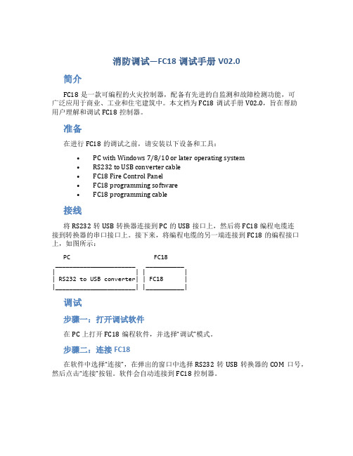
准备在进行FC18的调试之前,请安装以下设备和工具:•PC with Windows 7/8/10 or later operating system•RS232 to USB converter cable•FC18 Fire Control Panel•FC18 programming software•FC18 programming cable接线将RS232转USB转换器连接到PC的USB接口上,然后将FC18编程电缆连接到转换器的串口接口上。
接下来,将编程电缆的另一端连接到FC18的编程接口上,如图所示:PC FC18_______________________ ___________| | | || RS232 to USB converter| | FC18 ||_______________________| |___________|调试步骤一:打开调试软件在PC上打开FC18编程软件,并选择“调试”模式。
步骤二:连接FC18在软件中选择“连接”,在弹出的窗口中选择RS232转USB转换器的COM口号,然后点击“连接”按钮。
软件会自动连接到FC18控制器。
步骤三:调试参数在软件的“调试”界面中,可以设置和调试FC18的各种参数,如报警灯的亮度和声音的音量等。
具体操作如下:1.点击“设置”按钮,在弹出的窗口中选择需要调试的参数。
2.调整参数的值。
3.点击“应用”按钮将参数保存到控制器中。
步骤四:测试控制器在调试完成后,可以进行测试以确保控制器正常工作。
操作如下:1.点击“测试”按钮,在弹出的窗口中选择需要测试的控制器功能。
2.点击“测试”按钮进行测试。
结论通过本文档的指南,您现在应该已经掌握了使用FC18编程软件和编程电缆连接到PC的方法。
- 1、下载文档前请自行甄别文档内容的完整性,平台不提供额外的编辑、内容补充、找答案等附加服务。
- 2、"仅部分预览"的文档,不可在线预览部分如存在完整性等问题,可反馈申请退款(可完整预览的文档不适用该条件!)。
- 3、如文档侵犯您的权益,请联系客服反馈,我们会尽快为您处理(人工客服工作时间:9:00-18:30)。
火灾自动报警系统操作说明
一、首先把消防控制中心的火灾自动报警主机电源开关合上,为系统提供正常的供电电源(相对应指示灯亮)。
二、用户级别
1)本系统包含3个不同的用户级别(等级1是默认的任何人、等级2是保卫人员、等及3是调试人员)。
2)不同的用户等级有不同的权限和不同的界面,输入相对应等级的密码可登录不同级别的操作界面。
三、如何登录
1)按菜单键显示主菜单,选择登录选项按OK键,密码输入窗口弹出,键入相应的2/3级密码即可登录。
四、如何退出
1)系统自动退出:在没有任何操作的情况下,用户将在系统设定的登录时间过后自动退出到1级用户。
2)手动退出:按菜单键显示主菜单,选择登录选项下拉退出选项,按OK 键即可退出。
五、状态类型
1)报警主机包含了7种类型的状态:正常、火警/启动、故障、监管、屏蔽、测试/移动测试。
六、火警事件处理
1)按确认/消音键将蜂鸣器消音。
2)找出火警发生地点,通知相关人员现场核实火情。
3)真实火情:火情可控的情况下,现场人员利用就近灭火设施(灭火器、消火栓等)当场扑灭,处理完后按复位键。
如果火情很紧急,立即打电话报警,同时按下主机操作面板上的自动键(主机状态为手动模式下),进行一系列消防联动,疏散相关楼层人群,以免造成不必要的伤害。
4)虚假火情:相关人员现场检查报警范围内的情况,是否有大量灰尘或烟雾,情况正常,通知控制室人员对主机进行复位。
七、故障事件处理
1)按确认/消音键将蜂鸣器消音。
2)通知维保人员处理。
八、监管事件处理
1)按确认/消音键将蜂鸣器消音。
2)查看监管事件发生地点,根据实际情况判断是否要到现场进行处理。
九、启动/反馈事件处理
1)按确认/消音键将蜂鸣器消音。
2)查看启动/反馈发生地点根据实际情况判断是否要到现场进行处理。
十、实时事件查询
1)按菜单键显示主菜单事件菜单显示,选择任意一种需要查询事件,然后按OK键,全部符合要求的事件将被显示在浏览窗口中。
十一、如何进行屏蔽(隔离)/开放
1)当有建筑装修、设备损坏或失效时,需要对其进行屏蔽。
当装修或替换完成后,需立即将其开放,使其恢复到正常状态(被屏蔽的设备不会在向控制器发送信息)。
2)屏蔽操作:按菜单键进入主菜单,选择浏览子菜单,然后选择需要屏蔽设备所在的选项,按OK键。
如果不知道将需要屏蔽的设备属于哪种设备类型,选择“所有设备”,然后按“OK”键,树状图显示出来。
在树状图中通过站、回路、点一层一层向下查找,直到找到需要屏蔽/开放的设备,按“→”键弹出快捷菜单,然后按“↓”键选择“屏蔽”,再按“OK”
键,被选择的设备即被屏蔽,控制器即进入屏蔽状态,按“确认/消音”
键将蜂鸣器消音,同时确认/消音指示灯将从闪烁状态变为灭。
3)开放操作:通过查询屏蔽实时事件,然后按“→”键弹出快捷菜单,选择开放,在按OK键,被选择的设备即被开放。
十二、如何进行启动/停止
1)功能: 通过控制器手动启动或停止主板输出、输出模块、联动盘输出、声光控制等。
2)启动操作:按菜单键进入主菜单,选择浏览子菜单,然后选择需要启动设备所在的选项,按OK键。
如果不知道将需要启动的设备属于哪种设备类型,选择“所有设备”,然后按“OK”键,树状图显示出来。
在树状图中通过站、回路、点一层一层向下查找,直到找到需要启动或停止的设备,按“→”键弹出快捷菜单,然后按“↓”键选择“启动”,再按“OK”
键,被选择的设备即被启动,控制器即进入启动状态,按“确认/消音”
键将蜂鸣器消音,同时确认/消音指示灯将从闪烁状态变为灭。
3)停止操作:通过查询启动实时事件,然后按“→”键弹出快捷菜单,选择停止,再按“OK”键,被选择的设备即被停止。
