Manufacturing Tool V2 Work Flow
工厂布局和物料路径(英文版)

工厂布局和物料路径(英文版)Factory Layout and Material FlowIntroductionFactory layout and material flow are crucial elements in the efficient operation of a manufacturing facility. They refer to the arrangement of machinery, equipment, and workspaces within a factory, as well as the movement of materials throughout the production process. A well-designed factory layout and material flow can enhance productivity, minimize production costs, and optimize the use of available space. This article will discuss the key considerations and strategies involved in designing an effective factory layout and material flow.Factory Layout ConsiderationsWhen designing a factory layout, several key considerations need to be taken into account:1. Production Process: The layout should support the most efficient production process flow. This involves identifying the sequence of operations and organizing the workstations accordingly. For example, if the production process involves multiple assembly steps, it would be ideal to arrange the workstations in a linear fashion, enabling materials to move seamlessly from one station to the next.2. Space Utilization: The layout should make efficient use of available space. This can be achieved through careful planning and utilization of vertical space. For instance, vertical storage systems and mezzanine floors can be used to maximize storage capacityand free up floor space for production activities.3. Safety Measures: Occupational safety is of utmost importance in any manufacturing facility. The layout should incorporate safety measures, such as clear walkways, safety barriers, and proper ventilation, to ensure a safe working environment.4. Flexibility: The factory layout should be flexible enough to accommodate changes in production demand or process modifications. This can be achieved by using modular or movable equipment and workstations, allowing for easy reconfiguration. Material Flow StrategiesEfficient material flow is essential for minimizing production downtime, reducing inventory levels, and optimizing overall production efficiency. Several strategies can be employed to achieve this:1. Lean Manufacturing: Adopting lean manufacturing principles can significantly improve material flow. This involves analyzing the value stream and eliminating waste, such as unnecessary movement and transportation of materials. Implementing tools and techniques like Just-in-Time (JIT) inventory management and Kanban systems can help streamline material flow.2. Single Piece Flow: Single piece flow, also known as one-piece flow, entails moving one item at a time through the production process. This strategy helps identify and resolve bottlenecks, reduces inventory levels, and improves overall production efficiency.3. Material Handling Equipment: The appropriate selection and use of material handling equipment can greatly enhance material flow. Forklifts, conveyors, automated guided vehicles (AGVs), and robotics can be used to transport materials efficiently between workstations.4. Kanban System: A Kanban system is a visual method used to control production and inventory levels. It involves using cards or containers to signal the need for a replenishment of materials. This ensures a smooth material flow and prevents overproduction or stockouts.ConclusionDesigning an effective factory layout and material flow involves careful consideration of production processes, space utilization, safety measures, and flexibility. Implementing strategies such as lean manufacturing, single piece flow, and the use of appropriate material handling equipment can greatly improve material flow and overall production efficiency. By investing time and effort into designing and optimizing these aspects, manufacturers can enhance productivity, reduce costs, and maintain a competitive edge in today's demanding market.Factory Layout Considerations:In addition to the considerations mentioned earlier, here are a few more factors to consider when designing a factory layout:5. Workstation Ergonomics: The layout should prioritize the ergonomics of workstations to ensure the comfort and safety of workers. This includes considering factors such as workstation height, accessibility of tools and equipment, and minimizingrepetitive or strenuous motions.6. Material Flow Analysis: A thorough analysis of the material flow is essential for designing an efficient layout. This involves identifying potential bottlenecks, congestion points, and unnecessary movements of materials. By optimizing the material flow, production efficiency can be improved, and waiting times can be minimized.7. Maintenance Access: The layout should provide easy access to machinery and equipment for maintenance purposes. This includes ensuring sufficient space for maintenance personnel to work comfortably and ensuring that equipment can be easily moved or replaced when necessary.8. Future Expansion: It is important to consider the possibility of future expansion when designing the factory layout. This can be done by leaving available space for future equipment, ensuring the layout can accommodate increased production capacity, and considering the impact on material flow when expanding the facility.Material Flow Strategies:Let's delve deeper into the strategies that can be employed to optimize material flow within a manufacturing facility:5. Value Stream Mapping: A value stream map is a visual tool that helps identify the steps and processes involved in delivering a product to the customer. By analyzing the value stream, inefficiencies and waste can be identified and targeted forimprovement, ultimately leading to a smoother material flow.6. Batch Size Reduction: Reducing batch sizes can help reduce lead time and inventory levels, and improve material flow. By producing smaller batches, companies can respond to changes in customer demand more effectively and minimize the need for excess inventory.7. Standardized Work: Implementing standardized work processes can help streamline material flow. By establishing standard operating procedures and work instructions, employees can perform tasks consistently and efficiently, reducing variability and delays in material handling.8. Cross-Training: Cross-training employees to perform multiple tasks can help reduce bottlenecks and ensure a smooth material flow. By having a workforce that is versatile and capable of performing various tasks, the dependence on specific individuals can be minimized.9. Visual Management: The use of visual management techniques, such as clear signage, labels, and color-coding, can greatly improve material flow. These visual cues help employees quickly identify and locate materials, reducing search times and errors. 10. Continuous Improvement: Continuous improvement methodologies, such as Kaizen and Six Sigma, can be applied to continuously optimize material flow. By regularly analyzing and improving processes, companies can identify and eliminate waste, improve cycle times, and enhance overall efficiency.Conclusion:In conclusion, designing an effective factory layout and optimizing material flow are crucial for maximizing productivity and minimizing costs. By considering factors such as production processes, space utilization, safety measures, and flexibility, companies can create a layout that supports efficient operations. Implementing strategies like lean manufacturing, single piece flow, and the use of appropriate material handling equipment can further enhance material flow. By continuously analyzing and improving material flow, companies can achieve higher efficiency levels, reduce lead times, and maintain a competitive edge in the market.。
Manufacturing Automation

Optimum machine programming requires consideration of certain machine operating parameters including: • Positioning control • Compensations • Special machine features Positioning control is the ability to program tool and machine slide movement simultaneously along two or more axes. Positioning may be for point-to-point movement or for contouring movement along a continuous path. Contouring requires tool movement along multiple axes simultaneously. This movement is referred to as “Interpolation” which is the process of calculating intermediate values between specific points along a programmed path and outputting those values as a precise motion. Interpolation may be linear having just a start and end point along a straight line, or circular which requires an end point, a center and a direction around the arc.
Tooling Management工装管理程序(中英文)
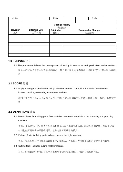
1.0 PURPOSE 目的1.1 The procedure defines the management of tooling to ensure smooth production and operation.定义工艺装备(简称工装)的规范管理,使其处于良好的技术状态,保证安全生产和工装正常运行。
2.1 SCOPE 范围2.1 Apply to design, manufacture, using, maintenance and control for production instruments,fixtures, moulds, measuring instruments and etc.适用于生产用夹具、刀具、模具、生产用检具等工装的设计、制造、使用、维护保养、报废等管理。
2.2 DEFINITIONS 定义3.1 Mould: Tools for making parts from metal or non-metal materials in the stamping and punchingmachine.模具:在工业生产中,用各种压力机和装在压力机上的专用工具,通过压力把金属材料或非金属材料制出所需形状的零件或制品,这种专用工具统称为模具。
3.2 Fixture: Tools for fixing parts to keep them in the right location.夹具:夹具是加工时用来迅速紧固工件,使机床、刀具和工件保持正确相对位置的工艺装置。
3.3 Cutting tool: Tools for cutting metal materials.刀具:机械制造中使用的刀具基本上都用于切削金属材料,一般为金属切削刀具。
3.4 Inspection tool: Tools for inspection.检具:生产中检验所用的工具。
4.0 REFERENCE DOCUMENTS 参考文件4.1 PD-S4-01 Facility and Equipment Management Procedure 设备设施管理程序5.0 RECORDS 记录5.1 FN-MA-005 Tooling Trail Run Report 设备/资产验收报告5.2 FN-TR-001 Tooling List 工装管理台帐5.3 FN-TR-002 Tooling History Record 工装履历表5.4 FN-MA-004 Equipment Repair Request 设备维修单5.5 FN-AC-001 Equipment/Asset Scrap Request 固定资产停用/报废单5.6 FN-MA-007 List of spare parts 备品一览表5.7 Consumable tooling replacement plan 易损工装更换计划6.0 RESPONSIBILITY 职责6.1 Tooling departments take charge of design, manufacture and verification for tooling. Developingfor supplier of tooling parts.模具部负责工装的设计,制造和验证及模具零配件供应商的开发。
机械英语常用词汇及对话
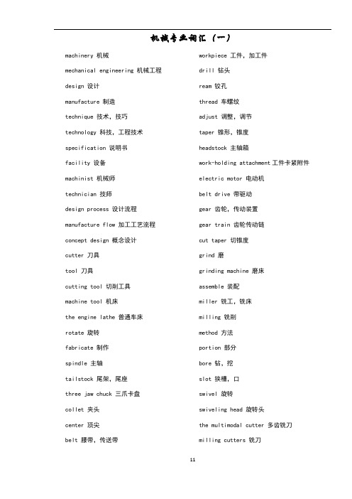
机械专业词汇(一)machinery 机械mechanical engineering 机械工程design 设计manufacture 制造technique 技术,技巧technology 科技,工程技术specification 说明书facility 设备machinist 机械师technician 技师design process 设计流程manufacture flow 加工工艺流程concept design 概念设计cutter 刀具tool 刀具cutting tool 切削工具machine tool 机床the engine lathe 普通车床rotate 旋转fabricate 制作spindle 主轴tailstock 尾架,尾座three jaw chuck 三爪卡盘collet 夹头center 顶尖belt 腰带,传送带workpiece 工件,加工件drill 钻头ream 铰孔thread 车螺纹adjust 调整,调节taper 锥形,锥度headstock 主轴箱work-holding attachment工件卡紧附件electric motor 电动机belt drive 带驱动gear 齿轮,传动装置gear train 齿轮传动链cut taper 切锥度grind 磨grinding machine 磨床assemble 装配miller 铣工,铣床milling 铣削method 方法portion 部分bore 钻,挖slot 狭槽,口swivel 旋转swiveling head 旋转头the multimodal cutter 多齿铣刀milling cutters 铣刀cut gear 加工齿轮vertical spindle machine 立式主轴铣床horizontal miller 卧式铣床arc 电弧welding 焊接joint 接头article 条款brazing 铜焊electrode 电极,电焊条holder 固定器worksite 工地,施工现场helmet 头盔leather apron 皮革制服safety equipment 安全装备glove 手套arc welding 电焊弧resistance welding 电阻焊接gas welding 气焊solid state welding 固态焊source of electric current 电流源leather apron 皮革制服bench 工作台benchwork 在工作台上完成的工作fitter 装配工manipulation 操纵mold 模子repair 修理worktable 工作台conveyor 传送者hardware 五金器具,硬件vice 台虎钳,老虎钳file 锉刀anvil 铁砧mounter 装配工,安装工operation 运转,操作mechanize 机械化case fitter 家具安装工hardware assemble 五金器具、硬件装配师movable vice with anvil 带有铁砧的可移动性台虎钳tilatable vice 倾动式的台虎钳case fitters 家具安装工rolling 辗压forging 锻造extruding 挤压stretching 拉伸straight bending 直弯casting 锻造molding 成型raw material 原材料metallurgy 冶金学,冶金术die 模具blacksmith 铁匠alloy 合金primary process 初加工工艺secondary process 精加工工艺manufacturing process机械加工工艺powder metallurgy 粉末冶金finishing operation 精整end product 最终产品molten metal 熔融金属production process 生产工艺shaping 刨光,刨削planning 刨平slab milling 平面铣face milling 端面铣broaching 拉削,推削grinding 磨削sawing 锯切flat surface machining 平面加工drilling 钻孔boring 镗孔reaming 铰孔metal removal 金属切削chip removal 有屑切削chipless removal 无屑切削metal removal by heat 热金属切削cylindrical surface machining 圆柱面加工punch 冲孔,打孔numerical control 数控punched card 穿孔卡片punched tape 穿孔带magnetic tape 磁性带work relationship 工件关系tool relationship 刀具关系smelt 精炼,冶炼furnace 炉子,熔炉heat treatment 热处理iron smelting 铁的熔炼physical characteristics 物理特性whole heat treatment 整体热处理surface heat treatment 表面热处理chemical heat treatment化学热处理heat-temperature 加热温度cooling method 冷却方式heating 加热annealing 退火quenching 淬火cutter 刀具grinder 磨工accident rate 事故发生率accident-free operation 零事故操作mechanical guarding 机械防护safety instruction 安全规章safety officer 安全管理员mechanism 机械装置panel 面板pipe 导管piston 活塞crankshaft 机轴,曲轴cam 凸轮valve 阀roller 滚筒,switch on 接通electronic control system 电控系统steel sheet 钢板wind resistance 风阻力aluminium alloy 铝合金back wheel 后轮spoke wheel 辐条车轮disc wheel 盘状车轮翻译对话 (1)Jay: How many machine tools are there in your factoryTommy: Ten.Jay: What kind of machine tools are theyTommy: There are four lathes, three milling machines, two shapers and one drilling machine.Jay: How many workers are there in your workshopTommy: There are nine.Jay: Are they all turnersTommy: No, seven of them are turners and two locksmiths.Jay: So no one can operate the milling machine.Tommy: No, six of the turners can operate it.Jay: Is there any womenTommy: There are eight women. Five are workers. Others are managers.Dialogue(2)A: Tom, you said that / you like to / be a machinist, /didn’t youB: Yes, sir. /An outstanding machinist!A: Then, do you know /what you have to learnB: Sorry, sir. I am not clear about / it enough. Could you tell me /something about itA: You should pay attention to /manufacture and design. This book introduces /basic knowledge about manufacture. You will benefit from it.B: Thank you so much. I will try my best to learn it. Oh, this machine / looks interesting. What is itA: It is a very useful tool / in machining. The engine lathe.B: What does it use forA: The engine lathe / is a very useful tool in machining. It can be used for / drilling, reaming, threading, cutting tapers.B: I’ve got it.Dialogue(3)A: Sir, I am not familiar with / the equipment / in our workshop. Could you please / give me a handB: Sure. Any questionsA: Is this a benchB: Yes, it is.A: How about those toolsB: This is a vice, and that is a file. This is not a tool / but a workpiece. A workpiece / is the material / to be manufactured.A: Ok, I see. What’s that big machineB: It’s the engine lathe. And altogether we have five lathes. Here we have / five turners / to operate those lathes.A: I heard that /the engine lathe / is one kind of machine tools. Am I rightB: Yeap. The engine lathe, / milling machine, / grinding machine, /drilling machine, /shaper /and sawing machine/ are machine tools. All of them /are important /in mechanical engineering.A: Are there /any other machine tools/ in our workshopB: Of course. We have three milling machines, / two shapers/ and four drilling machines. A: That’s great. Thank you for your explanation.Dialogue(4)A: Tom, do you know / what the original machine isB: It may be tools, / which were used by / the primitive men.A: Right. The first tools that the mankind made were stone falchions, stone axes and stone hammers. All kinds of complicated and accurate modern machines are developed from the simple tools of the ancient times step by step.B: Oh, I see, sir. That is the reason why we learn the mechanical history.Dialogue Translation (5):A: Tom, Do you know what is milling methodB: Sorry sir. I have no idea about it.A: Milling is a process of generating machined surfaces. The process employs relative motion between a workpiece and a rotating cutter. After the milling process, some kinds of required surfaces can be produced.。
模具相关英语词汇
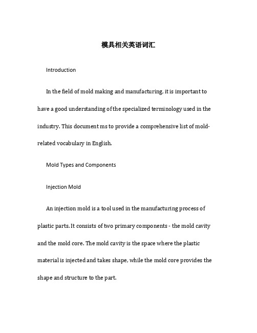
模具相关英语词汇IntroductionIn the field of mold making and manufacturing, it is important to have a good understanding of the specialized terminology used in the industry. This document ms to provide a comprehensive list of mold-related vocabulary in English.Mold Types and ComponentsInjection MoldAn injection mold is a tool used in the manufacturing process of plastic parts. It consists of two primary components - the mold cavity and the mold core. The mold cavity is the space where the plastic material is injected and takes shape, while the mold core provides the shape and structure to the part.Blow MoldBlow molding is a manufacturing process used to produce hollow plastic parts, such as bottles and contners. The blow mold is a specialized tool that shapes and forms the molten plastic into the desired shape.Compression MoldCompression molding is a molding process that involves placing a preheated material into an open mold cavity, then closing the mold to apply pressure and heat. The compression mold is responsible for providing the desired shape and structure to the final product.Ejector PinsEjector pins are small rods or pins that are used to push the finished parts out of the mold cavity. They are typically located at the back of the mold and are activated when the mold opens.Runner SystemThe runner system is a network of channels that allow the molten plastic material to flow from the injection machine into the mold cavity. It consists of the sprue, runners, and gates, which control the flow and distribution of the plastic material.Cooling SystemThe cooling system in a mold is responsible for regulating the temperature of the mold and the solidified parts. It usually involves the use of water channels or cooling pipes to dissipate heat and ensure efficient production.Mold Release AgentA mold release agent is a substance or compound applied to the mold surface to prevent the material from sticking to the mold. It allows for easy removal of the finished parts.Mold Design and Manufacturing ProcessesMold DesignMold design is the process of creating a blueprint or layout for the mold, specifying the dimensions, features, and detls of the mold cavity and core. It involves considering factors such as material selection, part design, and production requirements.CAD (Computer-ded Design)CAD is a software tool used for creating 2D and 3D models of mold designs. It allows for precise and accurate design representation, as well as the simulation and analysis of mold behavior.CAM (Computer-ded Manufacturing)CAM is a software tool used for generating toolpaths and instructions for the machining and manufacturing of molds. It helps streamline and automate the production process.CNC MachiningCNC (Computer Numerical Control) machining is a manufacturing process that uses computer-controlled machines to remove material from a workpiece and create the desired shape. It is often used in mold making for precision and accuracy.EDM (Electrical Discharge Machining)EDM is a machining process that uses electrical discharges to remove material from a conductive workpiece. It is commonly used for intricate and complex shapes in mold making.PolishingPolishing is the process of using abrasive materials and compounds to create a smooth and glossy surface finish on the mold cavity and core. It is important to achieve a high-quality surface finish to ensure proper part ejection and minimize defects.Mold AssemblyMold assembly involves the process of fitting together the various mold components, such as the cavity, core, ejector pins, and cooling system. It requires precision and careful alignment to ensure proper functioning of the mold.Mold TestingMold testing is conducted to evaluate the performance and functionality of the mold. It may involve producing sample parts, checking for defects, and making necessary adjustments before full-scale production.ConclusionHaving a good understanding of the mold-related terminology is essential for effective communication and collaboration in the mold making and manufacturing industry. This document has provided acomprehensive list of mold-related vocabulary in English, covering various mold types, components, design, and manufacturing processes.。
mfgtool failed to initialize memory
mfgtool failed to initialize memory怎么解决"MFGTool failed to initialize memory" 这个问题通常出现在使用MFGTool(Manufacturing Tool)烧录固件或操作系统时,表示MFGTool在初始化内存时遇到了问题。
解决这个问题的方法可能因环境和具体情况而异,但以下是一些常见的可能解决方案:1. 检查连接:-确保你的设备正确连接到计算机,并且连接是稳定的。
使用可靠的USB线缆,并检查设备是否被正确识别。
2. 重启设备和计算机:-尝试重新启动你的目标设备和计算机。
有时候,这可以清除临时的通信问题。
3. 更改USB端口:-尝试更改连接设备的USB端口。
有时,更换端口可以解决USB通信问题。
4. 更新驱动程序:-确保你的设备驱动程序是最新的。
去设备制造商的官方网站上查找并下载最新的驱动程序。
5. 检查目标设备状态:-确保你的目标设备处于正确的状态,例如处于烧录模式。
有时候,设备没有正确进入烧录模式可能导致初始化内存失败。
6. 查看MFGTool配置:-检查MFGTool的配置文件,确保设置正确。
有时候,错误的配置可能导致内存初始化失败。
7. 尝试其他版本的MFGTool:-如果可能的话,尝试使用MFGTool的其他版本。
有时,不同版本之间存在一些兼容性问题。
8. 联系设备制造商支持:-如果以上方法都无法解决问题,建议联系设备制造商的技术支持寻求进一步的帮助。
他们可能能够提供定制的解决方案或额外的支持。
请注意,这些建议是一般性的,具体的解决方案可能需要根据你的设备和环境进行定制。
Manufacturing Process生产过程管理程序(中英文)
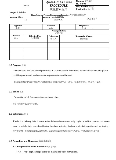
1.0 Purpose 目的To make sure that production processes of all products are in effective control so that a stable quality could be guaranteed, and customer requirements could be met.目的为确保公司所有产品的生产过程能够在有效的管理状态下进行,保证质量稳定,满足客户要求。
2.0 Scope 范围Production of all Components made in our plant.本公司所有产品的生产过程。
3.0 Definitions 定义Production delivery date: it refers to the delivery date marked in by Logistics. All the planned processes must be satisfactorily completed before the date, including the final products inspection and packaging.生产交货期:是指物流部确认的交货期,在此之前必须完成所有的生产过程,包括最终检验及包装。
4.0 Procedure and Flow chart 程序及流程图4.1 Responsibility and authority 职责与权限4.1.1 AQP dept, is responsible for making the work instructions.项目部负责作业指导书制定。
4.1.2 Process engineer and quality engineer are responsible for making the inspection instructionof production working procedure, and also responsible for planning reference points ofdifferent working procedure.工艺工程师与质量工程师负责制订生产过程工序检验指导书和过程检验标准,并负责策划各工序控制点以及生产工艺流程。
Manufacturing_and_Construction

R&D Pathway 4 C Current t St State-of-the-Art t f th A t
Target Innovation 1. Pre‐Planning & Lessons Learned (OE) Reinforcing Steel Density Reduction Reinforcing Steel Prefabrication Lifting and Rigging Current State Excellent progress in Japanese program and in US nuclear major component replacements. To be proven in US nuclear new build. Utility early project cash flow restrictions may be an impediment. Recent developments in commercial sector with use of high strength reinforcing steel and “headed headed rebar rebar”. Japanese program is getting great benefit from reinforcing steel prefabrication and use of “SC” walls. Large crane concept has been proven in Japanese program. Needs are for “flexible” flexible large crane approaches and increasing lifting speeds for very heavy components. Both are in development. Prefabrication is prevalent, modularization is gaining momentum, manufacturing is yet to be exploited but represents significant opportunity. Considerable progress in last five years in the availability of modeling software (BIM). Extensive Japanese use of models for planning. Wide acknowledgement that these are valuable and will be utilized in new nuclear nuclear.
机械设计制造模具专业英语
机械设计制造模具专业英语Introduction机械设计制造模具专业英语,也称作Mechanical Design and Manufacturing Mold English,是指在机械设计与制造模具领域使用的英语专业术语和表达方式。
机械设计制造模具专业英语在国际工程领域具有重要的地位,掌握这些专业英语词汇和表达方式是从事机械工程设计及制造模具工作的专业人员的基本要求。
Importance of Mechanical Design and Manufacturing Mold English随着经济全球化的发展,跨国企业之间的合作也越发频繁。
跨国机械设计制造模具领域的沟通与合作需要一种共同的语言,因此,机械设计制造模具专业英语的重要性愈发凸显。
1. 提高沟通效率机械设计制造模具专业英语的掌握可以有效提高与国外同行之间的沟通效率,减少误解和不必要的麻烦。
当进行跨国合作时,准确的理解对方的需求以及清晰地传达自己的设计意图非常重要,而机械设计制造模具专业英语的运用可以帮助实现这一目标。
2. 深入了解最新技术和工程领域进展机械设计制造模具专业英语是关于机械设计制造和模具领域的专业术语和表达方式的总结和归纳。
通过学习这些专业英语,可以更深入地了解最新的技术和工程领域进展。
同时,它也是获取国外设计制造模具资讯和技术文献的重要途径。
3. 提升竞争力掌握机械设计制造模具专业英语的人员在求职市场上具有更大的竞争优势。
在跨国企业或国际组织中,能够流利地运用机械设计制造模具专业英语的工程人员受到更高的重视,往往能获得更好的职业机会和发展前景。
4. 加强行业合作与交流机械设计制造模具专业英语的学习和应用也促进了国际间机械设计制造模具领域的合作与交流。
通过共同的语言,技术与经验可以更容易地共享和传递,从而促进行业的发展与进步。
Essential Vocabulary in Mechanical Design and Manufacturing Mold English下面是一些在机械设计制造模具专业英语中经常使用的关键词汇:1.Mechanical Design and Manufacturing Mold: 机械设计制造模具2.Tooling and Mold Making: 工装模具制造3.CAD/CAM: 计算机辅助设计/计算机辅助制造4.Tolerance: 公差5.Injection Molding: 注塑成型6.Die Casting: 压铸C Machining: 数控加工8.Rapid Prototyping: 快速原型制作9.Finite Element Analysis: 有限元分析10.Assembly: 装配这只是机械设计制造模具专业英语中的一小部分关键词汇。
完井工具介绍中英文版

Tubing Extension Joint 油管伸缩节
General Description: This product is used to compensate the axial expansion or shrinkage of tubing caused by well-treatment, water-injection or temperature changes.This product uses spline pin so that the torque can be transmitted at any position.
1、通过增加和减少剪切销钉调节剪切值; 2、工具可以通过剪切销钉完全锁定在全伸展、全收缩或中间冲 程位置; 3、足够长度的锁键可以提供全冲程扭矩传递; 4、上下连接扣型可以根据客户要求提供。
Tubing Extension Joint 油管伸缩节
Technical Specifications 技术参数
Technical Specifications
Demension
2-3/8 2-3/8 2-7/8 2-7/8 3-1/2 3-1/2 4-1/2 4-1/2 5-1/2 5-1/2
Max OD/in Sealing Bore /in
3.625 3.625 4.625 5.135 5.38 5.65 5.125 7.5 8.375 8.375
SS系列滑套是一种油、套通道的开关控制工具。它是通过标准 的钢丝作业来实现对滑套芯轴的打开与关闭,是一种油、气井 完井中分层开采的工具。
SS Serious Sliding Sleeve SS系列滑套
WorkShopManager自动化工具说明书
WorkShopManagerWorkShopManager offerS neW poSSibilitieSIt is generally thought that automated production is complicated to introduce and that it can only be appliedto long runs. The may be true when the robot grips the workpiece directly, but hardly when the workpiece is palletised.The handling units in System 3R’s automation programs are all intended to move pallets between a magazine and predefined chucks in one or more machines. When you work with pallets, the preparations are the same whether you are producing 100 different parts or 100 parts of the same type. When you have made the preparations for production in WorkShopManager, the operation of lifting the pallet into and out of the machine is not complicated at all. WorkShopManager has been developed …… to simplify the preparations for production in automatic cells… to maximise production capacity… to create the greatest possible flexibility… to ensure the security of the process. WorkShopManager is equally useful for manual loading of pallets in a single machine as for automatic production in a seven-axis linear robot cell, since this software grows with the task. Start with a single machine on the lowest level and then upgrade as your business develops.WorkShopManager SecureS the proceSSThe core of the system is a central database. All clients, machines and automation devices are in constant contact with the database.WorkShopManager links all machining processes together in a controllable and clearly-arranged production system. All machining data is available to the machines and can easily be transferred to the right machine at the right moment.User-friendly – necessary data are entered quickly and ina structured mannerQuick, precise overview of the entire process chainGreat flexibility – the order of priority can be changed at any timeSimpler, safer preparation of automatic cells. Information about workpieces, magazine positions, offset values and NC programs is always available.The risk of errors due to the human factor is minimised.Generates shorter lead timesGreater process securityOffers the possibility of automated one-piece productionJob status and machining times are recorded and stored in the database.Reports such as machining time per workpiece can be generated and transferred to a planning system.Alarm messages from machines and robots can be transferred via e-mail or SMS.All information about the machining is brought together in WorkCenter, which communicates with the database.In the database, a manufacturing order is created. This may contain:• an operation list• an NC program for the operation in question • documents linked to the operations • pallet identity • offset valuesWorkCenter does not produce its own data; it compiles information for every machining operation.The necessary information is fetched from the database and transferred to the machines.How the relevant order is executed depends on the type of cell…… manual creation of a batch with BatchBuilder, or … automatic execution with CellManager.A batch is a complete machining operation, containing several manufacturing orders with their magazine positions. This type of magazine loading can be regarded as static, since machining of the entire batch must be completed before changes can be made in the magazine.With CellManager, each individual job is startedaccording to a priority list. Here, you can change priorities and magazine content while the machine is working.EXECUTIONThe user-friendly procedure in WorkShopManager can be summarised in three stages: preparation, execution and monitoring.PREPARATIONSMONITORINGOrder creationIn WorkCenter, manufacturing orders can beorganised in accordance with the company’sstandard order structure.A manufacturing order covers one or moreidentical parts which may be located on one ormore pallets. The same pallet may also be carryingdifferent parts, each with its own manufacturingorder. This open structure offers great flexibilitywhen creating a manufacturing order.Article registerThe operation list can be saved as an article foruse if the part needs to be produced again. If anew order is created, based on an article, everymachining step and NC program will be present inthe new production order.Simpler and quickerReduces the risk of data entry errorsOption –planning system integrationWhen information is imported from ERP/MPS, amanufacturing order is created automatically.What then remains to be done is to place theworkpiece on its pallet, to identify it and to fetch anyoffset values from the measuring machine.Up-to-date machining information is fed back toERP/MPS for evaluation and post-calculation.IdentifyThe next step is to link the physical objects with their manufacturing orders.The object is mounted on a pallet with a code carrier which is recorded in the database.All information held in the database for that object can now be M integrationIf required, a measuring machine can be used before machining to determine offset values (X-Y -Z-C) for the workpiece on its pallet.The measurements are stored in a neutral format. They are then adapted and transferred to the machine tool.Reduces the risk of data entry errors Multi-pallet functionThere is no need to measure objects on multi-pallets. Every fixture on the pallet has a knownposition, and this automatically gives the objects the correct offset values.With this function, users can create their own multi-palletsEspecially suitable for milling applications Quality controlWhen the measuring machine has performed a geometrical inspection of the object and sent the status to the database, the object can be barred or released for further operations.Operation listsIn an operation list, the order of the variousmachining steps is defined. One operation must be complete before the next operation can start.DocumentsDocuments – machining instructions, reports,images, etc. – can be linked to every operation. This allows the operator to make use of the information directly at the machine.No searching for informationThe information is linked to the right machining operationIf the operation has been saved as an article, information from previous occasions will be available.Linked ordersFor an EDM operation, electrodes need to beproduced. Linking electrode manufacturing with the EDM operation minimises the risk of mistakes. As soon as the electrode blank has been identified on its holder, the electrode and the EDM operation are linked.The right electrode for the right EDM operation High process safety StatusThe status – waiting / machining / ready – of every object in the magazine is recorded in the database.cellManagerCellManager, which requires the pallets to have an identification system, manages the entire robot cell, handling all necessary data automatically. The cell is controlled entirely from the screen.• Starts the robot’s ID cycle.• Manages the pallet ID codes and magazine positions.• Displays the magazine content graphically.• Creates priority lists.• Automatically starts available jobs in the order of the priority list.• Updates the information in the database with the status and machining times of individual orders.Identification systemWhether you work with visual identification such as labels, or an electronic system with inductive readers and ID transponders, CellManager ensures the security of the process.Chaotic magazine loadingOn loading, the pallet is placed at the first available free magazine position.CellManager MultiManages a robot cell consisting of one robot and more than one machine, regardless of the type and make of the machines.Easy to change prioritiesThe order of priority of jobs can be changed while the machine is working.Easy to insert new jobsFinished workpieces can be lifted out of the magazine and new ones loaded into it, while the machine is working.Manually loaded machinesChaotic loading of a machine table with multiple chucks.After manual scanning of the machine table, a job list is created in CellManager. The jobs are then done in the sequence in the job list – one program at a time. The job sequence can be changed Automatic monitoringRobot-loaded machinesChaotic loading of the magazinesAfter automatic scanning of the magazine, a job list is created in CellManager.The jobs are then done in the sequence in the job list – one program at a time.The job sequence can be changed Automatic monitoringThe magazines can be lifted out and loaded while the machine is working.EXECUTION EXECUTION EXECUTION EXECUTION EXECUTIONEXECUTION EXECUTION EXECUTION EXECUTION EXECUTIONBatchBuilderBatchBuilder is a WorkCenter function for creating a complete machining operation – en batch – made up of several individual orders. You choose a number of orders and add magazine positions. The function then generates a main program with associated subprograms. The batch is transferred to the right machine and when the machine is started, the individual machining operations are executed – from the beginning to the end.Magazine positionsThe NC programs that were linked to the respective operation do not include the magazine positions. This information therefore must therefore beadded when the batch is created. This can be done manually or the information can be generated automatically.Simplified NC-programming.Loading listWhen the batch has been created, you can print out a loading list which describes the magazine positions of the objects.Less risk of loading at the wrong magazine positionTransfer of NC programsWhen creating the batch, you choose the machine or the cell that you want to perform the machining operation. The complete information is then transferred via the network. The magazines are loaded according to the loading list and the machining operation can start.Option – automatic electrode selection (AES)Automatically chooses the best electrode for the machining operation. Used to limit the number of electrodes when producing identical workpieces. However, for this function it is necessary to make an estimate of the electrode wear with coarse, intermediate and fine machining.You can, for instance, choose to “downgrade” the electrodes after the first bit. For the second bit you then use the first intermediate electrode for the coarse machining, the first fine electrode for the intermediate machining, and a new electrode for the fine machining.Option – cutting tool control (CTC)This function checks that all cutting tools that are needed for the milling operatins are available before machining starts.Option – RobotManagerOption for cells with industrial robot: CellManager handles communication between the various units of the cell, coordinates all activities, and monitors the status of every operation.MONITORING MONITORING MONITORING MONITORING MONITORINGCellManagerCellManager maintains constant contact with themachines and monitors what is happening in thecell.• When a machining operation starts and ends• What operation is being done• What object is in the machine• Messages coming from the maskinOption – AlarmServerAlarm messages from the machine and the robotcan be transferred via e-mail or SMS.WorkCenterAll information about the various operations issaved in the database. WorkCenter makes itpossible to use this information wherever youhappen to be.ReportingReports such as machining time per part can becreated and transferred to a production planningsystem (PPS).StatusWorkCenter keeps track of what is to be machined,and on which machine, as well as monitoring thestatus of jobs.Option –planning system integrationUp-to-date machining information can beautomatically fed back to ERP/MPS for evaluationand post-calculation.ModuleS in WorkShopManagerexaMpleS of applicationS1011baSic configurationSWorkShopManager is equally useful for manual loading of pallets in a single machine as forautomatic production in a seven-axis linear robotcell, since it grows with the task. Start with a single machine on the lowest level and then upgrade as your business develops.T -2219-E 08.05 S u b j e c t t o m o d i fi c a t i o n s • S y s t e m 3R , a m e m b e r o f t h e G e o r g F i s c h e r G r o u p .Combi, Delphin, Dynafix, Locx, LX, Macro, One Minute Set-Up, One System Partner, R2R, System 3R, VDP , WorkMaster, WorkPal, WorkPartner, WorkShopManager, 3HP , 3R, 3Ready-To-Run and 3Refix are registered trademarks of System 3R.EUROPESystem 3R Europe GmbH Wasserweg 19DE-64521, GROSS-GERAU tel +49 61 52 80 02 0fax +49 61 52 80 02 35**************************Chech Republic & SlovakiaSystem 3R Czech Tiskarska 10/257CZ-108 28 PRAHA 10tel +420 234 054 224fax +420 234 054 225**********************France & PortugalSystem 3R France56 Boulevard de Courcerin Les Espaces Multiservices 15F-77183 CROISSY BEAUBURG tel +33-01 60 95 90 80fax +33-01 60 37 88 16**************************Germany & BeNeLuxSystem 3R Deutschland Wasserweg 19DE-64521, GROSS-GERAU tel +49 61 52 80 02 0fax +49 61 52 80 02 35**************************Italy & SpainSystem 3R Italia Via Ponchielli, 2/4IT-20063 CERNUSCO SUL NAVIGLIO (MI)tel +39 02 92 38 821fax +39 02 92 11 23 19**************************ScandinaviaSystem 3R Nordic Sorterargatan 1SE-162 50 VÄLLINGBY tel +46-08 620 20 00fax +46-08 38 81 84**************************Järfälla Härdverkstad Elektronikhöjden 8SE-175 43 JÄRFÄLLA tel +46-08 580 125 50fax +46-08 580 126 55*****************Switzerland & AustriaSystem 3R Schweiz AG Wilerstrasse 98CH-9230 FLAWIL tel +41-071 394 13 50fax +41-071 394 13 60**************************Turkey & BulgariaSystem 3R TürkiyeAbdi Ipekci Cad. Ozel Idare Is Merk 150/209Bayrampasa 34030 ISTANBUL tel +90-212 613 8062-8063fax +90-212 613 8069******************************United KingdomSystem 3R UKRedvale House, New RoadPRINCES RISBOROUGH, Buckinghamshire HP27 0JN United Kingdom tel +44-01844 27 44 55fax +44-01844 34 88 00**************************ASIAFar East, China & IndiaSystem 3R Far East Pte.Ltd.6 Harper RoadLeong Huat Building, 01-01SINGAPORE SG-369 674tel +65-6289 4811fax +65-6289 3011**************************Shanghai Contact Office tel +86-21 6432 7927fax +86-21 6432 7928**************************Beijing Contact Office tel +86-10 8225 1632fax +86-10 8225 1635Guangdong Contact Office tel +86-769 8162 0628fax +86-769 8162 0638Malaysia Contact Office tel +60-03 7877 4785fax +60-03 7877 5948Taiwan Re gional Office tel +886-02 2278 3126fax +886-02 2278 3108Thailand Contact Office tel / fax +66-2 6422 764Japan & KoreaSystem 3R Japan CO., Ltd.Kaki Building2-5-22, Suido, Bunkyo-ku TOKYO JP-112-0005tel +81-03 5840-7383fax +81-03 5848-8723**************************Nagoya Regional Office tel +81-052 774 6250fax +81-052 774 6285Osaka Regional Office tel +81-06 6396 1500fax +81-06 6396 2855AMERICASystem 3R USA Inc.Headquarters & Technical Center 915 Busse RoadELK GROVE VILLAGE, US-IL 60007tel +1 847 439 4888fax +1 847 439 5099e-mail:********************Canada & Eastern MI116 Lynngate PlaceLondon Ontario Canada N6k 1S5Canadatel +1 519 870 8339, +1 248 320 1016 e-mail:***********************AZ, CA, CO, ID, MT, NM, NV, OR, TX, UT, WA, WY & Mexico1241 Celery LaneCorona, US-CA 91719Tel +1 909 226 1042e-mail:**********************1524 Valley Dr.Norco, US-CA 92860tel +1 714 299 4923e-mail:***************************IA, MN, ND, NE, SD & WI915 Busse RoadElk Grove Village, US-IL 60007tel +1 847 439 4888, +1 630 240 9825fax +1 847 439 5099e-mail:************************AR, IN, KY, OH & TN8466 Hill Pine CourtIndianapolis, US-IN 46227tel +1 317 215 4039, +1 317 694 7508fax +1 317 215 4041e-mail:*************************AL, FL, GA, LA, MS, NC & SC20934 Orchard Town nd O Lakes, US-FL 34638tel +1 813 326 0125e-mail:**************************IL, KS, MO, OK & Western MI915 Busse RoadElk Grove Village, US-IL 60007tel +1 847 439 4888, +1 630 240 9824fax +1 847 439 5099e-mail:******************************NJ, NY & PA67 Forest DrivePompton Plains, US-NJ 07444tel +1 201 248 3885e-mail:**************************CT, DC, DE, MA, MD, ME, NH, RI, VA, VT & WV915 Busse RoadElk Grove Village, US-IL 60007tel +1 847 439 4888, +1 201 214 7088fax +1 847 439 5099e-mail:************************System 3R International ABSorterargatan 1, SE-162 50 VÄLLINGBYtel+46-086202000,fax+46-087595234,e-mail:*****************,。
imx6的MFGTools配置、流程、分析
1、MFG说明MFGTool工具是freescale专门针对i.MX处理器专门使用的烧写工具,用来将编译好的文件系统和镜像文件烧写到板子上。
2、文件结构以明远智睿MY-I.MX6-MFG-TOOL-V2.3为例:文件结构cfg.ini指定LIST,ucl2.xml根据此定义,找到对应的操作部分流程://针对阶"> loadSection="OTH"setSection="OTH"HasFlashHeader="FALSE">LoadingInitramfs.</CMD> <CMDstate="BootStrap"type="jump">JumpingtoOSimage.</CMD>//通知内嵌ROM代码跳转到内存中的镜像执行<!--Pleaseuse"cat/proc/mtd"tochecktherightpartitionsforNAND,mtd0andmtd1areforSPI-NOR;mtd2-mtd6areforNAND --><!-- <CMDstate="Updater"type="push"body="mknodclass/mtd,mtd0,/dev/mtd0"/>//类型是push,此句在目标机上执行创建设备节点<CMDstate="Updater"type="push"body="mknodblock,mtdblock0,/dev/mtdblock0,block"/>-->//类型是push,此句在目标机上执行,创建设备节点<CMDstate="Updater"type="push"body="$flash_erase/dev/mtd000">ErasingBootpartition</CMD>//擦除信息<CMDstate="Updater"type="push"body="send"file="files/android/u-boot.bin">SendingU-Boot</CMD>//将files/android/u-boot.bin文件发送到目标机<CMDstate="Updater"type="push"body="$ddif=$FILEof=/dev/mtd0bs=512">writeU-BoottoSPI-NOR</CMD>//烧写将$FILE下载到/dev/mtd0位置,bs=512,指定读/写的blocks大小为512bytes <CMDstate="Updater"type="push"body="send"file="">Sendingpartitionshell</CMD> <CMDstate="Updater"type="push"body="$tarxf$FILE">Partitioning...</CMD>em.img">Sendingandwrittingsystem.img</CMD>//利用pipe传输大数据<CMDstate="Updater"type="push"body="frf">flushthememory.</CMD>//执行flush刷新操作,等到数据传输完毕<!--Writeuserdata.imgisoptional,forsomecustomerthisisneeded,butit'soptional.--><!--Also,userdata.imgwillhaveandroidunittest,youcanusethistodosomeautotest.--><!--<CMDstate="Updater"type="push"onError="ignore"body="pipeddof=/dev/mmcblk0p7"file="file/an droid/userdate.img">Sendinguserdata.img(optional)</CMD><CMDstate="Updater"type="push"body="frf">flushthememory.</CMD>-->//注释掉overy.img">Sendingandwrittingrecovery.img</CMD><CMDstate="Updater"type="push"body="frf">Finishingrootfswrite</CMD> <CMDstate="Updater"type="push"body="$echoUpdateComplete!">Done</CMD>//显示执行完毕信息</LIST>官方,LISTname=Android-SabreSD-eMMC<LISTname="Android-SabreSD-eMMC"desc="ChooseeMMCandroidasmedia"><!--AndroidProfile:--><CMDstate="BootStrap"type="boot"body="BootStrap"file="u-boot.bin">LoadingU-boot</CMD>//将blocks <CMDstate="Updater"type="push"body="$tarxf$FILE">Extractingdatapartitionshell</CMD> <CMDstate="Updater"type="push"body="$shmk-encryptable-data-android.sh/dev/mmcblk0/dev/mmcblk0p4">Makingdataencryptable</CMD><CMDstate="Updater"type="push"body="$mkfs.ext4/dev/mmcblk0p5">Formattingsystempartition</CMD><CMDstate="Updater"type="push"body="$mkfs.ext4/dev/mmcblk0p6">Formattingcachepartition</CMD><CMDstate="Updater"type="push"body="frf">flushthememory.</CMD> <CMDstate="Updater"type="push"body="$mkfs.ext4/dev/mmcblk0p7">Formattingdevicepartition</CMD>em.img">Sendingandwrittingsystem.img</CMD><CMDstate="Updater"type="push"body="frf">flushthememory.</CMD> <!--Writeuserdata.imgisoptional,forsomecustomerthisisneeded,butit'soptional.--><!--Also,userdata.imgwillhaveandroidunittest,youcanusethistodosomeautotest.--><!--<CMDstate="Updater"type="push"onError="ignore"body="pipeddof=/dev/mmcblk0p7"file="file/an droid/userdate.img">Sendinguserdata.img(optional)</CMD><CMDstate="Updater"type="push"body="frf">flushthememory.</CMD>--><CMDstate="Updater"type="push"body="pipeddof=/dev/mmcblk0p2bs=512"file="files/android/rec overy.img">Sendingandwrittingrecovery.img</CMD>-f flashandroidimage.EOF}#checktheifroot?userid=`id-u`if[$userid-ne"0"];thenecho"you'renotroot?"exitfi#parsecommandlinemoreoptions=1node="na"cal_only=0flash_images=0not_partition=0not_format_fs=0while["$moreoptions"=1-a$#-gt0];docase$1in-h)help;exit;;-s)cal_only=1;;-f)flash_images=1;;RECOVERY:${RECOVERY_ROM_SIZE}MB SYSTEM:${SYSTEM_ROM_SIZE}MB CACHE:${CACHE_SIZE}MBDATA:${data_size}MBMISC:${MISC_SIZE}MBEOFexitfi#destroythepartitiontableddif=/dev/zeroof=${node}bs=1024count=1sfdisk--force-uM${node}<<EOF,${boot_rom_sizeb},83,${RECOVERY_ROM_SIZE},83,${extend_size},5,${data_size},83,${SYSTEM_ROM_SIZE},83,${CACHE_SIZE},83,${VENDER_SIZE},83,${MISC_SIZE},83EOF#adjustthepartitionreserveforbootloader.MfgtoolusesglobalconfigurationtorecognizewhichdevicetheuserwantstoflashamongdifferentUSBdevicesconnectedtothePC.选择设备与PC相连的USBLet’sexplainitbyanexample.下面为例,说明<CFG><STATEname="BootStrap"dev="MX6Q"vid="15A2"pid="0054"/><STATEname="Updater"dev="MSC"vid="066F"pid="37FF"/></CFG>Globalconfigurationiscontainedbetweenparameter<CFG>and</CFG>.定义的全局配置参数<STATEname="BootStrap"dev="MX6Q"vid="15A2"pid="0054"/>indicatesthefirstphaseoftheburningpro cess,thephasenameis“BootStrap”,andadevicenamed“MX6Q”shouldbeconnectedwiththeUSBpid“0054”an dvid“15A2”.Fori.MX6serial,inthephase“BootStrap”,thevalidstringsfordevare:“MX6Q”,“MX6D”,“MX6S L”;inthephase“Updater”,thevalidstringfordevis:“MSC”.烧录过程的第一步BootStrap<STATEname="Updater"dev="MSC"vid="066F"pid="37FF"/>indicatesthesecondphaseoftheburningproc ess,thephasenameis“Updater”,andadevicenamed“MSC”shouldbeconnectedwiththeUSBpid“37FF”andvid“066F”.theonlythinghosthastodoistosendthecommandtothetargeteddevice.主机只是将命令发给目标机ThecommandsactuallyexecutedbyOSimagearedownloadedin Commandlists.Asaresult,eachOShasitsowncomx6qpll8:50MHzBoard:i.MX6Q-SABRESD:unknown-boardBoard:0x63012[POR]BootDevice:SPINORI2C:readyDRAM:1GBMMC:FSL_USDHC:0,FSL_USDHC:1,FSL_USDHC:2UsingdefaultenvironmentIn:serialOut:serialErr:serialNet:gotMACaddressfromIIM:00:00:00:00:00:00FEC0[PRIME]Hitanykeytostopautoboot:0##BootingkernelfromLegacyImageat...ImageType:ARMLinuxKernelImage(uncompressed)DataSize:3182360Bytes=3MBVerifyingChecksum...OK##LoadinginitRamdiskfromLegacyImageat10c00000...ImageName:ubootinitramfsrootfsImageType:ARMLinuxRAMDiskImage(gzipcompressed)DataSize:4537478Bytes=4.3MBmodules:0x7f000000-0x7fe00000(14MB).text:0x8003a000-0x805b676c(5618kB).bss:0x806062a4-0x806316f0(174kB)SLUB:Genslabs=13,HWalign=32,Order=0-3,MinObjects=0,CPUs=4,Nodes=1 PreemptiblehierarchicalRCUimplementation.NR_IRQS:624MXCGPIOhardwaresched_clock:32bitsat3000kHz,resolution333ns,wrapsevery1431655msarm_max_freq=1GHzMXC_EarlyserialconsoleatMMIO0x2020000(options'115200')bootconsole[ttymxc0]enabledConsole:colourdummydevice80x30Calibratingdelayloop...1581.05BogoMIPS(lpj=7905280)pid_max:default:32768minimum:301Mount-cachehashtableentries:512CPU:Testingwritebuffercoherency:ok hwperfevents:enabledwithARMv7Cortex-A9PMUdriver,7countersavailableCPU1:BootedsecondaryprocessorCPU2:BootedsecondaryprocessorCPU3:BootedsecondaryprocessorBroughtup4CPUs11usbcore:registerednewdevicedriverusbimx-ipuv3imx-ipuv3.0:IPUDMFCNORMALmode:1(0~1),5B(4,5),5F(6,7) imx-ipuv3imx-ipuv3.1:IPUDMFCNORMALmode:1(0~1),5B(4,5),5F(6,7)Bluetooth:Corever2.16NET:Registeredprotocolfamily31Bluetooth:HCIdeviceandconnectionmanagerinitializedBluetooth:HCIsocketlayerinitializedBluetooth:L2CAPsocketlayerinitializedBluetooth:SCOsocketlayerinitializedi2c-core:driver[max17135]usinglegacysuspendmethodi2c-core:driver[max17135]usinglegacyresumemethodSwitchingtoclocksourcemxc_timer1Clockevents:couldnotswitchtoone-shotmode:Clockevents:couldnotswitchtoone-shotmode:Clockevents:couldnotswitchtoone-shotmode:dummy_timerisnotfunctional.Clockevents:couldnotswitchtoone-shotmode:CouldnotswitchtohighresolutionmodeonCPU2dummy_timerisnotfunctional.dummy_timerisnotfunctional.CouldnotswitchtohighresolutionmodeonCPU1CouldnotswitchtohighresolutionmodeonCPU0JFFS2version2.2.(NAND)漏2001-2006RedHat,Inc.msgmnihasbeensetto2017cryptodev:driverloaded.ioschedulernoopregisteredioschedulerdeadlineregisteredioschedulercfqregistered(default)mxc_sdc_fbmxc_sdc_fb.0:registermxcdisplaydriverldb_regulator_get:get()withnoidentifierimx-ipuv3imx-ipuv3.0:IPUDMFCDPHIGHRESOLUTION:1(0,1),5B(2~5),5F(6,7) Console:switchingtocolourframebufferdevice128x37mxc_sdc_fbmxc_sdc_fb.1:registermxcdisplaydriverhdmimxc_hdmimxc_hdmi:DetectedHDMIcontroller0x13:0xa:0xa0:0xc1fbcvt:1920x1080@60:CVTName-2.073M9------------[cuthere]------------WARNING:atmm/page_alloc.c:2121__alloc_pages_nodemask+0x150/0x64c()Moduleslinkedin:[<800469f0>](unwind_backtrace+0x0/0xf8)from[<800731b8>](warn_slowpath_common+0x4c/0x64) [<800731b8>](warn_slowpath_common+0x4c/0x64)from[<800731ec>](warn_slowpath_null+0x1c/0x24)[<800731ec>](warn_slowpath_null+0x1c/0x24)from[<800bf5b4>](__alloc_pages_nodemask+0x150/0x64c)imx-uart.4:ttymxc4atMMIO0x21f4000(irq=62)isaIMXloop:moduleloadedm25p80spi0.0:sst25vf016b(2048Kbytes)Creating2MTDpartitionson"m25p80":0x000000000000-0x000000180000:"bootloader"0x000000180000-0x000000200000:"kernel"GPMINANDdriverregistered.(IMX)vcan:VirtualCANinterfacedriverFECEthernetDriverfec_enet_mii_bus:probedInitializingUSBMassStoragedriver...22usbcore:registerednewinterfacedriverusb-storageUSBMassStoragesupportregistered.ARCUSBOTGDeviceControllerdriver(1August2005)addwakeupsourceirq75g_file_storagegadget:controller'fsl-usb2-udc'notrecognized check_parameters:UTPsettingsareinplacenow,overridingdefaults g_file_storagegadget:Noserial-numberstringprovided!g_file_storagegadget:File-backedStorageGadget,version:1September2010 g_file_storagegadget:NumberofLUNs=1fsl-usb2-udc:bindtodriverg_file_storagemxc_asrcregistered22usbcore:registerednewinterfacedriverusbhidusbhid:USBHIDcoredriverCirrusLogicCS42888ALSASoCCodecDriveri2c-core:driver[cs42888]usinglegacysuspendmethodi2c-core:driver[cs42888]usinglegacyresumemethodimx_3stackasocdriverALSAdevicelist:Nosoundcardsfound.TCPcubicregisteredNET:Registeredprotocolfamily17NET:Registeredprotocolfamily29Bluetooth:RFCOMMTTYlayerinitializedBluetooth:RFCOMMsocketlayerinitializedBluetooth:RFCOMMver1.11Bluetooth:BNEP(EthernetEmulation)ver1.3Bluetooth:BNEPfilters:protocolmulticastBluetooth:HIDP(HumanInterfaceEmulation)ver1.2VFPsupportv0.3:implementor41architecture3part30variant9rev4BusfreqdrivermoduleloadedBusfreqdriverEnabledcpu_idis0//<CMDstate="Updater"type="push"body="$flash_erase/dev/mtd000">ErasingBootpartition</CMD>UTP:receivedcommand'$flash_erase/dev/mtd000'UTP:executing"flash_erase/dev/mtd000"Erasing4Kibyte@17f000--100%complete//4k4*1024=4096UTP:sendingSuccesstokernelforcommand$flash_erase/dev/mtd000.utp_poll:passreturned.//<CMDstate="Updater"type="push"body="send"file="files/android/u-boot.bin">SendingU-Boot</CMD>UTP:receivedcommand'send'UTP:sendingSuccesstokernelforcommandsend.//<CMDstate="Updater"type="push"body="$ddif=$FILEof=/dev/mtd0bs=512">writeU-BoottoSPI-NOR</CMD>UTP:receivedcommand'$ddif=$FILEof=/dev/mtd0bs=512'UTP:executing"ddif=$FILEof=/dev/mtd0bs=512"442+1recordsin442+1recordsout226788bytes(221.5KB)copied,7.148058seconds,31.0KB/sUTP:sendingSuccesstokernelforcommand$ddif=$FILEof=/dev/mtd0bs=512.Newsituation:Units=mebibytesof1048576bytes,blocksof1024bytes,countingfrom0DeviceBootStartEndMiB#blocksIdSystem/dev/mmcblk0p10+1516-16383+83Linux/dev/mmcblk0p216238819283Linux/dev/mmcblk0p3241103108011059205Extended/dev/mmcblk0p4110438152712277708883Linux/dev/mmcblk0p524+535512-524287+83Linux/dev/mmcblk0p6536+1047512-524287+83Linux/dev/mmcblk0p71048+10558-8191+83Linux/dev/mmcblk0p81056+10638-8191+83LinuxWarning:partition4extendspastendofdiskSuccessfullywrotethenewpartitiontableRe-readingthepartitiontable...mmcblk0:p1p2p3<p5p6p7p8>p4mmcblk0:p4size5554176extendsbeyondEOD,truncatedIfyoucreatedorchangedaDOSpartition,/dev/foo7,say,thenusedd(1)tozerothefirst512bytes:ddif=/dev/zeroof=/dev/foo7bs=512count=1(Seefdisk(8).)Checkingthatno-oneisusingthisdiskrightnow...mmcblk0:p1p2p3<p5p6p7p8>p4Warning:partition4extendspastendofdiskSuccessfullywrotethenewpartitiontableRe-readingthepartitiontable...mmcblk0:p1p2p3<p5p6p7p8>p4mmcblk0:p4size5554176extendsbeyondEOD,truncatedIfyoucreatedorchangedaDOSpartition,/dev/foo7,say,thenusedd(1)tozerothefirst512bytes:ddif=/dev/zeroof=/dev/foo7bs=512count=1(Seefdisk(8).)UTP:sendingSuccesstokernelforcommand$shmksdcard-android.sh/dev/mmcblk0.utp_poll:passreturned.//<CMDstate="Updater"type="push"body="$ls-l/dev/mmc*">Formattingsdpartition</CMD>UTP:receivedcommand'$ls-l/dev/mmc*'UTP:executing"ls-l/dev/mmc*"brw-r-----1rootdisk179,0Jan100:00/dev/mmcblk0brw-r-----1rootdisk179,8Jan100:00/dev/mmcblk0boot0brw-r-----1rootdisk179,16Jan100:00/dev/mmcblk0boot1brw-r-----1rootdisk179,1Jan100:00/dev/mmcblk0p1brw-r-----1rootdisk179,2Jan100:00/dev/mmcblk0p2brw-r-----1rootdisk179,3Jan100:00/dev/mmcblk0p3brw-r-----1rootdisk179,4Jan100:00/dev/mmcblk0p4brw-r-----1rootdisk179,5Jan100:00/dev/mmcblk0p5UTP:executing"mkfs.ext4-Ldata/dev/mmcblk0p4"mke2fs1.41.4(27-Jan-2009)Filesystemlabel=dataOStype:LinuxBlocksize=4096(log=2)Fragmentsize=4096(log=2)171024inodes,684032blocks34201blocks(5.00%)reservedforthesuperuserFirstdatablock=021blockgroups32768blockspergroup,32768fragmentspergroup8144inodespergroupSuperblockbackupsstoredonblocks:32768,98304,163840,229376,294912Writinginodetables:doneCreatingjournal(16384blocks):doneWritingsuperblocksandfilesystemaccountinginformation:doneThisfilesystemwillbeautomaticallycheckedevery33mountsor180days,etune2fs-cor-itooverride.UTP:sendingSuccesstokernelforcommand$mkfs.ext4-Ldata/dev/mmcblk0p4.UTP:receivedcommand'$mkfs.ext4-Lcache-O^extent/dev/mmcblk0p6' UTP:executing"mkfs.ext4-Lcache-O^extent/dev/mmcblk0p6"mke2fs1.41.4(27-Jan-2009)Filesystemlabel=cacheOStype:LinuxBlocksize=1024(log=0)Fragmentsize=1024(log=0)131072inodes,524284blocks26214blocks(5.00%)reservedforthesuperuserFirstdatablock=164blockgroups8192blockspergroup,8192fragmentspergroup2048inodespergroupSuperblockbackupsstoredonblocks:8193,24577,40961,57345,73729,204801,221185,401409Writinginodetables:doneCreatingjournal(8192blocks):doneWritingsuperblocksandfilesystemaccountinginformation:doneThisfilesystemwillbeautomaticallycheckedevery35mountsor180days,etune2fs-cor-itooverride.//<CMDstate="Updater"type="push"body="frf">flushthememory.</CMD>UTP:receivedcommand'frf'UTP:sendingSuccesstokernelforcommandfrf.utp_poll:passreturned.//<CMDstate="Updater"type="push"body="$mkfs.ext4/dev/mmcblk0p8">Formattingmiscpartition</CMD>UTP:receivedcommand'$mkfs.ext4/dev/mmcblk0p8'UTP:executing"mkfs.ext4/dev/mmcblk0p8"mke2fs1.41.4(27-Jan-2009)Filesystemlabel=OStype:LinuxBlocksize=1024(log=0)Fragmentsize=1024(log=0)2048inodes,8188blocks409blocks(5.00%)reservedforthesuperuserFirstdatablock=1Maximumfilesystemblocks=83886081blockgroup8192blockspergroup,8192fragmentspergroup2048inodespergroupWritinginodetables:done10592+0recordsin10592+0recordsout5423104bytes(5.2MB)copied,1.458177seconds,3.5MB/sUTP:closingthefileUTP:sendingSuccesstokernelforcommandfrf.utp_poll:passreturned.//<CMDstate="Updater"type="push"body="$echoUpdateComplete!">Done</CMD> UTP:receivedcommand'$echoUpdateComplete!'UTP:executing"echoUpdateComplete!"UpdateComplete!UTP:sendingSuccesstokernelforcommand$echoUpdateComplete!.utp_poll:passreturned.。
工厂常用英文翻译

工厂常用英文翻译工廠常用英語翻譯(機械、模具。
)一、组织机构及职位总经理办公室General manager’s office模具部T ooling department项目部Project department品质部Quality department计划部 Plan department制造部Manufacture departmentKeypad产品部Keypad departmentIMD 产品部 IMD department五金部 Metal stamping department设计科 Design section冲压车间 Stamping workshop电镀车间 Plating workshop物控科 Production material control section计划科 Plan section仓务科 Warehouse section商务科 Business section品质规划科 quality plan sectionIQC科 IQC sectionIPQC科 IPQC sectionOQC科 OQC section检测中心 measurement center项目规划科 Project plan section项目XX科 Project section XX试模科 Mold test section成本科 Cost section设备科 Facility section采购科 Purchase section综合办 General affairs office编程科 Programming section模具工程科T ooling engineering section 模具装配车间Mold assembly workshop文控中心Document control center (DCC)注塑车间Injection workshop喷涂车间 Spray painting workshop装配车间Assembly workshop总经理General manager (GM)经理managerXX部门经理Manager of XX department原料库 Raw material warehouse半成品库Semi-finished product warehouse 成品库Finished product warehouse科长 section chief主任 chief部门主管 department head主管, 线长supervisor组长Foreman, forelady秘书secretary文员clerk操作员operator助理assistant职员staff二、产品超声波焊接ultrasonic welding 塑胶件 Plastic parts塑材 Raw parts喷涂件 Painted parts装配件 Assembly parts零件 Component原料 Raw material油漆 Paint稀释剂 Thinner油墨 Ink物料编号part number三、模具注塑模具injection mold冲压模具Stamping tool模架mold base定模座板Fixed clamp plate A板A plateB板B plate支承板 support plate方铁 spacer plate回位销 Return pin导柱 Guide pin动模座板Moving clamp plate 顶针ejector pin单腔模具single cavity mold 多腔模具multi-cavity mold 浇口gate合模力clamping force锁模力locking force开裂crack循环时间cycle time老化aging螺杆screw镶件 Insert主流道 sprue分流道runner浇口gate直浇口 direct gate点浇口pin-point gate测浇口edge gate潜伏浇口submarine gate浇口套sprue bush流道板runner plate排气槽vent分型线(面)parting line 定模Fixed mold动模movable mold型腔cavity凹模cavity plate,凸模core plate斜销angle pin滑块slide拉料杆sprue puller定位环locating ring脱模斜度draft滑动型芯slide core螺纹型芯threaded core热流道模具hot-runner mold 熔合纹weld line 三板式模具three plate mold脱模ejection脱模剂release agent注射能力shot capacity注射速率injection rate注射压力injection pressure保压时间holding time闭模时间closing time电加工设备Electron Discharge Machining数控加工中心CNC machine center万能铁床Universal milling machine平面磨床Surface grinding machine万能摇臂钻床Universal radial movable driller 立式钻床Vertical driller倒角chamfer键Key键槽keyway间距pitch快速成型模Rapid prototype tool (RPT)四、品管SPC statistic process control品质保证Quality Assurance(QA)品质控制Quality control(QC)来料检验IQC Incoming quality control巡检IPQC In-process quality control校对calibration环境试验Environmental test光泽gloss拉伸强度tensile strength盐雾实验salt spray test翘曲warp比重specific gravity疲劳fatigue撕裂强度tear strength缩痕sink mark耐久性durability抽样sampling样品数量sample sizeAQL Acceptable Quality level 批量lot size抽样计划sampling plan抗张强度 Tensile Strength抗折强度 Flexural Strength硬度 Rigidity色差 Color Difference涂镀层厚度 Coating Thickness 导电性能 Electric Conductivity 粘度 viscosity附着力 adhesion耐磨 Abrasion resistance尺寸 Dimension(喷涂)外观问题 Cosmetic issue不合格品 Non-conforming product限度样板 Limit sample五、生产注塑机injection machine冲床Punch machine嵌件注塑 Insert molding双色注塑 Double injection molding薄壁注塑 Thin wall molding膜内注塑IMD molding ( In-mold decoration)移印Tampo printing丝印 Silk screen printing热熔 Heat staking超声熔接 Ultrasonic welding (USW)尼龙nylon黄铜 brass青铜 bronze紫(纯)铜 copper料斗hopper麻点pit配料compounding涂层coating飞边flash缺料 Short mold烧焦 Burn mark缩水 Sink mark气泡 Bubbles破裂 Crack熔合线 Welding line 流痕 Flow mark银条 Silver streak黑条 Black streak表面光泽不良Lusterless表面剥离Pelling翘曲变形Deformation脏圬 Stain mark油污 Oil mark蓝黑点 Blue-black mark顶白 Pin mark拉伤 Scratch限度样品 Limit sample最佳样品 Golden sample预热preheating再生料recycle material机械手 Robot机器人 Servo robot试生产 Trial run; Pilot run (PR)量产 mass production 切料头 Degate产能 Capacity能力 Capability参数 Parameter二次加工 Secondary process六.物控保质期shelf lifeABC分类法ABC Classification装配Assembly平均库存Average Inventory批号Batch Number批量生产Mass Production提货单Bill of Lading物料清单Bill of Material采购员Buyer检查点Check Point有效日期Date Available修改日期Date Changed结束日期Date Closed截止日期Date Due生产日期Date in Produced库存调整日期Date Inventory Adjust 作废日期D ate Obsolete 收到日期Date Received交付日期Date Released需求日期Date Required需求管理Demand Management需求Demand工程变更生效日期Engineering Change Effect Date呆滞材料分析Excess Material Analysis完全跟踪Full Pegging在制品库存In Process Inventory投入/产出控制Input/ Output Control检验标识Inspection ID库存周转率Inventory Carry Rate准时制生产Just-in-time (JIT)看板Kanban人工工时Labor Hour最后运输日期Last Shipment Date提前期Lead Time负荷Loading仓位代码Location Code仓位状况Location Status批量标识Lot ID批量编号Lot Number批量Lot Size机器能力Machine Capacity机器加载Machine Loading制造周期时间Manufacturing Cycle Time制造资源计划Manufacturing Resource Planning (MRP II)物料成本Material Cost物料发送和接收Material Issues and Receipts物料需求计划Material Requirements Planning (MRP)现有库存量On-hand Balance订单输入Order Entry零件批次Part Lot零件编号Part Number (P/N)零件Part领料单Picking List领料/提货Picking产品控制Product Control产品线Production Line采购订单跟踪Purchase Order Tracking需求量Quantity Demand毛需求量Quantity Gross安全库存量Safety Stock在制品Work in Process零库存Zero Inventories七.QS-9000中的术语APQP Advanced Product Quality Planning and Control Plan,产品质量先期策划和控制计划PPAP Production Part Approval Process,生产件批准程序FMEA Potential Failure Mode and Effects Analysis,潜在失效模式及后果分析MSA Measure System Analysis,测量系统分析SPC Statistical Process Control,统计过程控制审核 Audit能力 Capability能力指数 Capability Indices控制计划 Control Plans纠正措施 Corrective Action文件 Documentation作业指导书Standard operation procedure (SOP); Work instruction 不合格品 Nonconformance不合格 Nonconformity每百万零件不合格数 Defective Parts Per Million, DPPM预防措施 Preventive Action程序Procedures过程流程图 Process Flow Diagram, Process Flow Chart 质量手册Quality Manual质量计划 Quality Plan质量策划 Quality Planning质量记录Quality Records原始数据Raw Data反应计划Reaction Plan返修Repair返工Rework现场Site分承包方Subcontractors产品product质量quality质量要求quality requirement顾客满意customer satisfaction质量管理体系quality management system 质量方针quality policy质量目标quality objective质量管理quality management质量控制quality control质量保证quality assurance组织organization顾客customer供方supplier过程process服务service设计与开发design and development:特性characteristic可追溯性trace ability合格conformity缺陷defect纠正correction让步concession放行release报废scrap规范specification检验inspection试验test验证verificatio评审review测量measurement。
Unit 8 Flexible Manufacturing System

11、Routing has to do with the AGV’s ability to make decisions that allow it to select the appropriate route as it moves across the shop floor。 路径选择是涉及AGV的作出决策的能力,当AGV在穿越 车间时,该决策能使它选择最合适的路径。
15、Light load vechicles,as the name suggests, are used in manufacturing setting where the material to be moved is neither heavy nor bulky. 就如名称所表明的,轻载车是制造环境中用来搬运 不重又不庞大的材料
12、Traffic management devices such as stop signs,yield signs,caution lights,and stop lights are used to control traffic in such a way as to prevent collisions and to optimize traffic flow and traffic patterns 交通管理设备例如终止标志,让路标志,警 示灯以及红灯这些方式来控制车辆,从而来阻止 碰撞及优化车流及交通模式。
一系列的自动化机床,或是相互联系在一起的制造设备 的名目有:自动化材料处理系统,递阶式数字可编 程计算机控制系统,以及在预先设置类别内,提供零件 和部件的随机制造。
3、Regardless of how broadly or narrowly FMS is defined,sevsral key item emerge as critical to general definition of FMS ,and repeat themselves through a crass-section of standard definitions. 不管是广义FMS还是狭义FMS,一些关键项目的 出现对FMS的一般定义来说是至关重要的,并且他们在 各标准定义的剖析中经常出现。
Lean-Manufacturing-资料+精讲+案例介绍
Equipment
Hardware
库存周转
Controls & Measuring
40%的提高
Electronic & Electrical
Industrial Equipment
Handtools and Hardware
稍有应用/不应用
Controls & Measuring
Benchmark Results 定标结果
5 0
化装品
50 年前 现在
玩具 机床 食品 药品
Product Styles In Supermarket 超级市场之商品种类
60000
40000
20000
0
1970
1980
1990
2000
Life Cycle Cost In Different System 不同系统中的成本
大规模生产模式下的 产品生命周期成本
• Emphasize on lead time reduction
• Improve asset utilization
• Built to customer demand
• 在同步生产的基 础上,强调缩短 生产周期
• 提高资源利用率 • 需求驱动
• Remove constraints to respond to customer demand through the entire supply pipeline (supplier-customer)
1997 IWeek Survey of 2,900 manufacturers 1998 IWeek Survey of 2,100 additional manufacturers
Fusion Digital Power Manufacturing GUI用户指南说明书
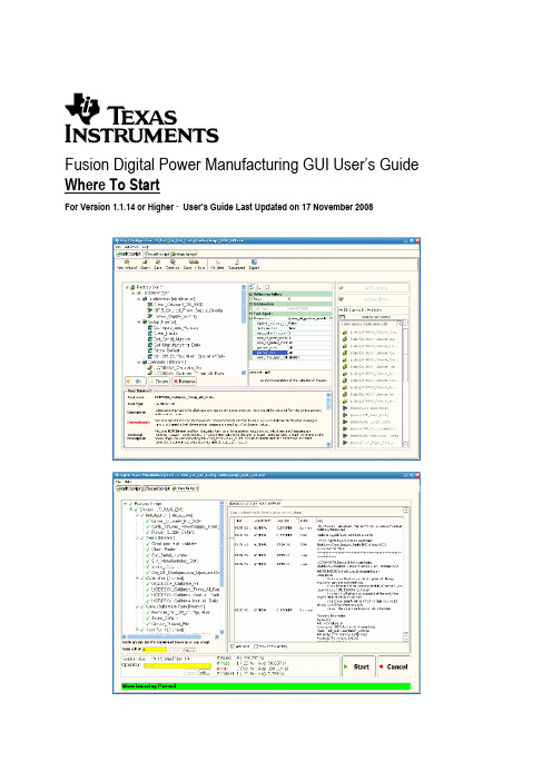
Fusion Digital Power Manufacturing GUI User’s Guide Where To StartFor Version 1.1.14 or Higher· User’s Guide Last Updated on 17November 2008IMPORTANT NOTICETexas Instruments and its subsidiaries (TI) reserve the right to make changes to their products or to discontinue any product or service without notice, and advise customers to obtain the latest version of relevant information to verify, before placing orders, that information being relied on is current and complete. All products are sold subject to the terms and conditions of sale supplied at the time of order acknowledgment, including those pertaining to warranty, patent infringement, and limitation of liability.TI warrants performance of its products to the specifications applicable at the time of sale in accordance with TI’s standard warranty. Testing and other quality control techniques are utilized to the extent TI deems necessary to support this warranty. Specific testing of all parameters of each device is not necessarily performed, except those mandated by government requirements.Customers are responsible for their applications using TI components.In order to minimize risks associated with the customer’s applications, adequate design and operating safeguards must be provided by the customer to minimize inherent or procedural hazards.TI assumes no liability for applications assistance or customer product design. TI does not warrant or represent that any license, either express or implied, is granted under any patent right, copyright, mask work right, or other intellectual property right of TI covering or relating to any combination, machine, or process in which such products or services might be or are used. TI’s publication of information regarding any third party’s products or services does not constitute TI’s approval, license, warranty or endorsement thereof.Reproduction of information in TI data books or data sheets is permissible only if reproduction is without alteration and is accompanied by all associated warranties, conditions, limitations and notices. Representation or reproduction of this information with alteration voids all warranties provided for an associated TI product or service, is an unfair and deceptive business practice, and TI is not responsible nor liable for any such use.Resale of TI’s products or services with statements different from or beyond the parameters stated by TI for that product or service voids all express and any implied warranties for the associated TI product or service, is an unfair and deceptive business practice, and TI is not responsible nor liable for any such use.Also see: Standard Terms and Conditions of Sale for Semiconductor Products. /sc/docs/stdterms.htmMailing Address:Texas InstrumentsPost Office Box 655303Dallas, Texas 75265Copyright © 2007, Texas Instruments IncorporatedTexas Instruments Page 1Programs task libraries in .NET.Creates a script by selecting specifictasks that a particular device needs atmanufacturing.Browses to the script location and simplyclicks RUN!Texas Instruments Page 21F USION D IGITAL P OWER M ANUFACTURING U SER G UIDES1.1Script Runner (File: Manuf GUI - Script Runner.doc)For users who will:1.Load a manufacturing script file.2.Run a script on device(s).This document walks the user through launching the application, selecting a script, loading a script, and executing it. This guide also describes how the execution is logged and where to find logs.1.2Script Writer (File: Manuf GUI - Script Writer.doc)For users who will:1.Create manufacturing scripts for device(s).I.Select specific tasks for a particular manufacturing of a device. For example, the user will selectCalibrate Vout, calibrate Iout and configure them accordingly.II.Edits manufacturing scripts.This document walks the user through creating a script that can be used in manufacturing. Starts by explaining how to add items to a script, then how to save, export and automatically generate a document explaining the script made that can be saved as the manufacturing procedure for a device. Also shows how to use a built-in template to calibrate the UCD9240 in manual and instrumented mode. The document Manuf GUI - Script Runner should be read before this.1.3Task Developer (File: Manuf GUI – Task Developer.doc)For users who will:1.Create tasks that can be referenced in a script, using a .NET programming language such as C# or.2.Implement drivers to allow for instrumented manufacturing.This document walks the user through setting up the development environment to creating a task that can be used by the manufacturing GUI.Texas Instruments Page 3。
工业软件 英语词汇

工业软件英语词汇Industrial Software: Key Components and Applications.Industrial software, often referred to as enterprise software or industrial applications, refers to a broadrange of software solutions designed to automate, manage, and optimize various industrial processes. These software systems play a crucial role in enhancing productivity, efficiency, and decision-making within manufacturing, logistics, energy, and other heavy industries.Key Components of Industrial Software.1. Enterprise Resource Planning (ERP): ERP systems integrate various business processes, including procurement, inventory management, sales, marketing, and finance, into a single, unified software solution. These systems providereal-time data and insights, enabling better decision-making and increased operational efficiency.2. Manufacturing Execution Systems (MES): MES are designed to manage and optimize manufacturing processes, from raw material procurement to finished product dispatch. These systems provide real-time data on production status, equipment performance, and quality control, enabling manufacturers to make informed decisions.3. Supply Chain Management (SCM): SCM software helps companies manage their supply chain operations, including procurement, inventory management, logistics, and distribution. These systems aim to optimize the flow of goods and information, reducing costs and improving customer satisfaction.4. Product Lifecycle Management (PLM): PLM software covers the entire lifecycle of a product, from concept to design, development, production, and service. It helps companies manage product data, collaborate across departments, and ensure compliance with industry standards and regulations.5. Industrial Automation and Control Systems: Thesesystems are designed to automate industrial processes, including manufacturing, energy management, and logistics. They use various sensors, actuators, and controllers to monitor and control equipment, ensuring optimal performance and safety.Applications of Industrial Software.1. Manufacturing: Industrial software is widely used in manufacturing to automate production processes, manage inventory, track materials and products, and ensure quality control. MES and ERP systems are particularly important in this context, enabling manufacturers to respond quickly to market changes and improve overall efficiency.2. Logistics and Distribution: SCM and other industrial software solutions help companies manage their supply chain operations, ensuring the efficient flow of goods and information. These systems enable real-time tracking of inventory, orders, and shipments, enabling companies to reduce costs, improve customer satisfaction, and respond quickly to unexpected events.3. Energy Management: Industrial software is crucial in the energy sector, where it is used to monitor and control power generation, transmission, and distribution. These systems help energy companies optimize their operations, reduce waste, and ensure compliance with environmental regulations.4. Process Industries: In industries such as chemicals, pharmaceuticals, and food processing, industrial softwareis used to automate and optimize production processes. These systems ensure precise control over process parameters, improving product quality and reducing waste.Conclusion.Industrial software is a vital component of modern industrial operations, enabling companies to automate, manage, and optimize their processes. By integratingvarious business functions and providing real-time data insights, these systems help companies improve productivity, efficiency, and decision-making. As technology continues toevolve, we expect to see more innovative and intelligent industrial software solutions that further transform industrial operations.。
FUJITSU Manufacturing Industry Solution COLMINA Di
Overview FUJITSU Manufacturing Industry Solution COLMINA Digital Manufacturing FJVPSOverview of Service / Solution FUJITSU Manufacturing Industry Solution COLMINA Digital ManufacturingFJVPSVirtual Product and Process SimulatorThe global standards tool of digital manufacturingFJVPS⏹What is FJVPS?⏹Customers Benefits⏹Features⏹Case Study⏹Module functionsWhat is FJVPS?Digital ManufacturingVDR/VMRAssembly process designMan hour calculationAssembly animationOutputting to documents3D CADE-BOMSupports production preparation work such as assembly procedure, man-hour calculation, process design, resource review, assemblyability evaluation, business form creation and worker education.Cooperate and share3D-data and assembly information(assemble procedure,tact time, work method, Work allotment, location,resource, etc.)M-BOM BOP Assembly evaluation3D data completely linksProcess Flow#1:Data courtesy of :KYOCERA Document Solutions Inc.#2 :Virtual Design Review #3 :Virtual Manufacturing reviewCustomer Benefits-50-80% of the design error was detected on a virtual prototype beforehand. -The remaining defect item concerning assembly vanished before it approved. -The drawing change rate after approval became 1/6.-Defective assembly was able to be reduced to 1/5 in 1.5 years.-The assembly trouble 80% reduction that was the initial goal was achieved in four years.Q: Quality improvementC: Productivity enhancement and cost reduction-The start-up period of the prototype was able to be adjusted to 1/15.-The development period was shortened to six months, and the development cost was reduced to 1/2.-FJVPS harness option was used, and the design period was able to be moved up for one month.D: Shortening at lead time and period-The man-hour of making the work procedure manual has been reduced by 30-40%.-Communication between design and other business segment have been improved.-Suggestions for improvement(ex. Mechanism operation, assembly, and check of serviceability) became possible without a real machine.-The metal mold correction cost was reduced by half by the front-loading by FJVPS.FJVPS realizes, improvement of quality and production time of the early period of mass production as well as early improvement with design quality.The simple operation that even a CAD inexperienced person is usable.Benefits by FJVPS FJVPS Harnessmaking the work procedure manual* Cooperate with FJGP4D#1#2,3#1#1#1#1Shop layout simulationWork instruction manualThese information can be registered with Operation Library and can be insert in MFG Flow automatically. Manufacturing flow information and snapshots of each process are output by 1 operation and are used for various document making. Not only making time is shortened, but also can prevent the leak of the correction by outputting it from the latest 3D model data.Assembly man-hour can be calculated while checking 3D model.Evaluation attributeparameterBatch assembly animation generationSnapshot of the assembling workFJVPS distinguishes the installation direction of the part without depending on the product shape and defines an assembling direction and the viewpoint direction of the part for creating assembling animation by 1 operation. Because it can insert the assembling line, auto shape and images, it is possible to express the intention of the engineer easily clearly.inserted by a operation unit.inserted by group ofoperations.Resource balanceResource assignmentLine balance simulationEasy to edit to the structure and procedure for assembling the CAD assembly structure.Checking toolChecking operationDynamic interference check / easy route modificationHuman / Tool model verification Create / Review HarnessThe harness follows the moving parts. The length of the harness is calculated automatically.Work instructions on the production lineThe screen display switches according to the progress of work.It is also possible to record working hours.FJVPS Assembly Instruction ViewerAssembly process designCAD StructureAssemble FlowFJVPS MFG FlowOperation information (structure, procedure, man-hour, jig/tool, auxiliary material and so on) necessary for product assembly can be entered on FJVPS MFG Flow.Man hour calculationOperation LibraryIt is also possible to simulate the line balance by using the calculated man-hour information and 3D assembly animation.Create assembly animationOutputting to documentsParts control tableParts list#1#1ContactFUJITSU LIMITEDE-mail:************************Information in this document is as of March,2022 and is subject to change without notice.ModuleD i s p l a y 3D -m o d e l s h a p eD i s p l a y M F G f l o w , M F G a n i m a t i o n p l a y b a c kM e a s u r e m e n t , C r o s s s e c t i o nC r e a t e / r e v i e w h a r n e s sC r e a t e a s s e m b l y a n n o t a t i o n sE d i t a s s e m b l i n g f l o wA s s e m b l y / d i s a s s e m b l y a n i m a t i o n c r e a t i o nD e t e c t i n g c o l l i s i o n s i n a n i m a t i o nO u t p u t f l o w i n f o , O u t p u t s n a p s h o t sI n t e r f e r e n c e /c l e a r a n c e c h e c kM e c h a n i s m s e t t i n gH u m a n , T o o l sD e s i g n r e v i e wE n g i n e e r i n g c h a n g eM a n -h o u r e s t i m a t i o nA s s e m b l a b i l i t y e v a l u a t i o nO p e r a t i o n l i b r a r yP r o c e s s s p l i t , R e s o u r c e a s s i g n m e n tE d i t p r o c e s s i n f o r m a t i o n T o u c h p a n e l o p e r a t i o n s FJVPS Standard ◆◆◆◆◆◆◆◆◆◆◆◆◆◆◆◆◆◆◆FJVPS Harness◆FJVPS Assembly Animation (Create Assembly Animation)◆◆◆◆◆◆◆◆◆FJVPS Document Interface ◆FJVPS Viewer◆◆◆◆FJVPS Assembly Instruction Viewer◆◆◆FJVPS Standard, Harness: Floating license FJVPS Assembly Animation, Document Interface : Floating license and Stand alone license FJVPS Viewer: license free FJVPS Standard necessary to run FJVPS Harness.FJVPS Assembly Animation is necessary to run FJVPS Document Interface.CAD Data InterfaceNX, PTC Creo Elements/Direct , PTC Creo Parametric, SolidWorks, Solid Edge, CATIA V5*, Autodesk Inventor, FJICAD SX, FJICAD MX, Parasolid*, JT*, STL, VML 2.0All Interfaces except CATIA V5, JT and Parasolid * are offered free.Module functionsShimadzu Corporation (analytical & measuring instruments)(1) The start of production duties was hastened by a design revue using FJVPS.Rework and frequency of trial productions of actual equipment were decreased.(2) Man-hours required for document preparation were cut in half.assembly procedure sheets, parts lists, service manuals, instruction manuals, etc.Man-hours required for the illustrations of harnesses and cables has been reduced by 10%. (3) Product information data sharing with the FJVPS server.Work efficiency, consistency and maintainability are improvedAMADA (Metalworking machinery and devices )Reduction of indirect operations, logistic cost, and improvement of maintenance serviceability have been achieved in addition to a 50% reduction of the product development period.(1) Promoting front loading, and aiming at reduction of development period & cost reduction.It was possible to shorten the period from development to release on the market to 11 months, which had conventionally required about 2 years.(2) A study/review for grouping and routing of wiring, hoses, etc. by utilizing FJVPS is executed from the planning stage.The development man-hour and time related to wiring and piping were reduced by 40%.(3) FJVPS has also been utilized for the study/review on optimization of efficient loading methods on trucks as well as containers foroverseas transportation. The success of such efforts has brought about a 19% reduction in logistic expense and a 30% reduction in the logistic delivery period.Jatco (Automatic transmission for automobiles)(1) Challenges in reducing lead time before starting mass production.Jatco has undertaken formulation of the environment for utilizing 3D data where the functions of products, component characteristics and names, relationship with preceding & post processes about components to be assembled in charge, and precautions for safety can be learnt virtually(2) Work proficiency before formulation of a mass-production line is realized using the animation function of FJVPS.・The staff in charge of the production site can routinely make full use of DMU, and feedback knowledge of the site into the animation for work proficiency by themselves.・The variability of the teacher side was also reduced on a global scale on certain projects, and as a result, the man-hours on the student side after proficiency was also reduced by nearly 40%.Liquid chromatograph mass spectrometer “LCMS -IT-TOF”Animation for proficiency in work at vital pointsPrior study/review, decision of wiring and piping routes。
小学上册Y卷英语第3单元暑期作业(含答案)

小学上册英语第3单元暑期作业(含答案)英语试题一、综合题(本题有100小题,每小题1分,共100分.每小题不选、错误,均不给分)1.What do we call the study of space?A. GeologyB. AstronomyC. BiologyD. Physics答案:B2.What is the term for the study of weather?A. BiologyB. GeologyC. MeteorologyD. Astronomy答案:C3.The beach is crowded in the hot ______ (夏天).4.In a chemical reaction, the starting materials are called _____.5.I enjoy _____ (reading/writing) stories.6.What do we call a person who studies animals?A. BiologistB. ZoologistC. BotanistD. Ecologist答案:B7.I enjoy going ________ (远足) in nature.8.What is the opposite of cold?A. WarmB. HotC. CoolD. Chilly9.What is the color of an orange fruit?A. GreenB. PurpleC. OrangeD. Blue10.I feel ________ (兴奋) about the trip.11.The main gas used in welding is ______.12.The dolphin is a ______ (社交的) animal.13.What do we use to clean our teeth?A. SoapB. ToothbrushC. TowelD. Comb14.When it rains, I play with my _________ (室内玩具) instead of going outside.15. A chemical reaction that releases heat is called an _____ reaction.16.The __________ (历史的叙述) tells our stories.17.My favorite dish is ______ (香肠).18.He is a _____ (发明家) aiming for sustainability solutions.19.What is the capital city of Yemen?A. Sana'aB. AdenC. TaizD. Al Hudaydah20.What do we call a person who studies the impact of technology on culture?A. TechnologistB. SociologistC. AnthropologistD. Historian答案:A21. A porcupine uses its quills for ______ (自我保护).22. A ______ (植物工厂) can grow food year-round.23. A ____ is known for its ability to imitate sounds.24.The chemical symbol for neodymium is _______.25.What is the largest continent?A. AfricaB. AsiaC. EuropeD. America答案:B26.The __________ (历史的传承) carries forward our legacy.27.What do we call the first letter of the alphabet?A. BB. AC. CD. D答案:B28.He likes to play _______ (soccer/basketball).29.What color is the sky on a clear day?A. GreenB. BlueC. RedD. Purple30.What is the capital of New Zealand?A. AucklandB. WellingtonC. ChristchurchD. Dunedin答案:B31.What do you call a person who takes photographs?A. ArtistB. PhotographerC. PainterD. Illustrator答案:B32.The ______ (小鸟) chirps happily in the morning.33.根据短文内容,选出Tom和 Chen Jie 书包里的物品。
- 1、下载文档前请自行甄别文档内容的完整性,平台不提供额外的编辑、内容补充、找答案等附加服务。
- 2、"仅部分预览"的文档,不可在线预览部分如存在完整性等问题,可反馈申请退款(可完整预览的文档不适用该条件!)。
- 3、如文档侵犯您的权益,请联系客服反馈,我们会尽快为您处理(人工客服工作时间:9:00-18:30)。
Manufacturing Tool V2 (MFGTool2) WorkflowContentsOverview (2)The first thing you need to do is to tell MFGTool2 what kind of SoC it works on. (2)The second thing you need to do is tell MFGTool2 where it can get ucl2.xml. (2)Define the max number of devices you want to operate at the same time. (2)Specify the target storage and target board. (3)Prepare the binary files for operation list. (3)After all this necessary information is implemented, MFGTool2 begins to work: (4)© Freescale Semiconductor, Inc., 2012. All rights reserved.OverviewThis document describes the relationship between MFGTool2.exe, cfg.ini, UICfg.ini, ucl2.xml, the operation list defined in ucl2.xml, and the binary files which will be used in the burning process.The basic function of MFGTool2 is to burn the image to a specific storage on a specific target (board) with a specific SoC.The first thing you need to do is to tell MFGTool2 what kind of SoC it works on.Q: Why does MFGTool2 need this information?A: The MFGTool2 is based on the USB, different SoCs have differentPID/VID, and MFGTool2 needs this information to monitor the devicetree to get the exactly right Device on which it manipulates.Q: How to provide this information to MFGTool2?A: By using the ucl2.xml. One ucl2.xml is used for a specific SoC. Atthe beginning of the ucl2.xml, a <CFG> pare term defines the SoCname and the PID/VID for it. The detailed information about <CFG>can be found in the “Manufacturing Tool V2 UCL user manual.doc”The second thing you need to do is tell MFGTool2 where it can get ucl2.xml.Q: How to let MFGTool2 know where it can get the ucl2.xml?A: By using the cfg.ini. In this cfg.ini, there is a[profiles]chip = MX6Q Linux UpdateMFGTool2 will try to find the ucl2.xml with the path (relative path tomfgtool2.exe) Profiles\${chip}\OS Firmware. If you take the abovechip value as an example, MFGTool2 will try to find the ucl2.xml at“Profiles\MX6Q Linux Update\OS Firmware”.Define the max number of devices you want to operate at the same time.Q: Why does MFGTool2 need this information?A: MFGTool2 needs this information to create the related structure,thread, and UI related resource.Q: How to configure it?A: By using UICfg.ini. In this file, only PortMgrDlg needs to beconfigured.Specify the target storage and target board.Q: Why do you need this information?A: Since different boards may have different uboot.bin file anddifferent kernel image, the user needs to differentiate them.Additionally, the operation on a different target and board will bedifferent too.Q: How to differentiate storage and board?A: By using the operation list defined in ucl2.xml. One operation listis dedicated to defining a specific storage on a specific board.Q: I have defined many different operation lists. How do I letMFGTool2 know which one should be used?A: By using the cfg.ini. In this cfg.ini, there is[LIST]name = Sabre-SDMFGTool2 will try to find the operation list named “Sabre-SD” in theucl2.xml which should allocate at Profiles\${chip}\OS Firmware. Prepare the binary files for operation list.Q: What kind of binary files are needed?A: Two kinds of binary files:1)The ram kernel and the corresponding U-Boot run on thetarget board.2)The normal kernel and the corresponding U-Boot which will beused by end user on the target.Q: Where should I put these binary files?A: It is decided by the operation list. For example, the following isextracted from operation “Sabre-SD” defined in Profiles\MX6Q LinuxUpdate\OS Firmware\ucl2.xml<CMD state="BootStrap" type="boot" body="BootStrap" file ="u-boot-mx6q-sabresd.bin" >Loading U-boot</CMD><CMD state="BootStrap" type="load" file="uImage"address="0x10800000"loadSection="OTH" setSection="OTH"HasFlashHeader="FALSE" >Loading Kernel.</CMD><CMD state="Updater" type="push" body="send" file="files/u-boot-mx6q-sabresd.bin">Sending u-boot.bin</CMD><CMD state="Updater" type="push" body="send"file="files/uImage">Sending kernel uImage</CMD>The file name marked by red indicates where to find this file, andrelated path to the ucl2.xml.Q: Which binary files are ram kernel images and which are normalimages?A: Usually, the command “BootStrap” is used to burn ram kernel.So, in the above case, u-boot-mx6q-sabresd.bin, uImage is ramkernel and files/u-boot-mx6q-sabresd.bin, files/uImage is normalkernel.Q: How can I generate these binaries?A: The user needs to refer to “Mfgtool Linux or Android FirmwareDevelopment Guide V2.docx” and generate ram kernel image. How togenerate normal binary is out of MFGTool scope.After all this necessary information is implemented, MFGTool2 begins to work:1)Parse the operation list to get all the commands which need tobe executed.2)Monitor the device tree to get the exactly right device withthe PID/VID defined by <CFG> in ucl2.xml3)After you find right device, use the PID/VID to get the rightburn phase (state). Different phases (states) have differentPID/VID pares.The detailed information about phase (state) can be found in“Manufacturing Tool V2 UCL user manual.doc” and“Manufacturing Too l V2 Quick Start Guide.doc.”4)Get the commands according to the phase (state) in Step3.5)Execute commandsHow to Reach Us:Home Page: Web Support: /support Information in this document is provided solely to enable system and software implementers to use Freescale products. There are no express or implied copyright licenses granted hereunder to design or fabricate any integrated circuits based on the information in this document.Freescale reserves the right to make changes without further notice to any products herein. Freescale makes no warranty, representation, or guarantee regarding the suitability of its products for any particular purpose, nor does Freescale assume any liability arising out of the application or use of any product or circuit, and specifically disclaims any and all liability, including without limitation consequential or incidental damages. “Typical” parameters that may be provided in Freescale data sheets and/or specifications can and do vary in different applications, and actual performance may vary over time. All operating parameters, including “typicals,” must be validated for each customer application by customer’s technical experts. Freescale does not convey any license under its patent rights nor the rights of others. Freescale sells products pursuant to standard terms and conditions of sale, which can be found at the following address: /SalesTermsandConditions.Freescale, the Freescale logo, AltiVec, C-5, CodeTest, CodeWarrior, ColdFire, C-Ware, Energy Efficient Solutions logo, Kinetis, mobileGT, PowerQUICC, Processor Expert, QorIQ, Qorivva, StarCore, Symphony, and VortiQa are trademarks of Freescale Semiconductor, Inc., Reg. U.S. Pat. & Tm. Off. Airfast, BeeKit, BeeStack, ColdFire+,CoreNet, Flexis, MagniV, MXC, Platform in a Package, QorIQ Qonverge, QUICC Engine, Ready Play, SafeAssure, SMARTMOS, TurboLink, Vybrid, and Xtrinsic are trademarks of Freescale Semiconductor, Inc. All other product or service names are the property of their respective owners. The Power Architecture and word marks and the Power and logos and related marks are trademarks and service marks licensed by . The ARM Powered Logo is a trademark of ARM Limited.© Freescale Semiconductor, Inc. 2012. All rights reserved.。
