sx59wxy小结1-3模块
艾茨顿9SX电源模块说明书
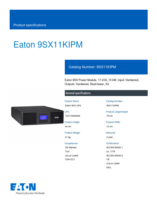
Eaton 9SX11KIPMEaton 9SX Power Module, 11 kVA, 10 kW, Input: Hardwired,Outputs: Hardwired, Rack/tower, 3UGeneral specificationsEaton 9SX UPS9SX11KIPM74317203939270 cm44 cm13 cm21 kg 2 yearCE Marked TUVcULus Listed CSA 22.2IEC/EN 62040-1 UL 1778IEC/EN 62040-2 CEcULus Listed EACProduct Name Catalog Number UPC Product Length/Depth Product Height Product Width Product Weight Warranty Compliances CertificationsView runtime graph No batteryYes Hardwired230V10 kW0.9200/208/220/230/240/250 V +/- 1%Sine wave230V default (200/208/220/230/240/250V) 21Online/Double-conversion11 kVAHardwired/fixed connection230V default (200/208/220/230/240/250V) 50/60 Hz>.99176-276 V (100-276 V with derating)NoRuntime graphBattery replacement Battery quantityBattery management Extended battery capability ReceptacleVoltageWattageOutput power factorOutput voltage rangeOutput waveformOutput nominal voltageVoltage distortion output (linear load) - max Feed typeTopologyVA ratingInput connection Input nominal voltage Nominal frequency Input power factor Input voltage range Includes network card CommunicationABM & Temperaturecompensated chargingmethod (user selectable)Automatic battery testDeep discharge protectionAutomatic recognition ofexternal battery unitsUSB port (HID compliant)Serial port (RS232)Mini terminal block forremote On/OffMini-terminal block forremote power offDry contacts (4 outputs,relay, DB9)40-70 HzNoMultilingual graphical LCD display YesOne slot for optional communication card Eaton Intelligent Power Manager, Eaton Intelligent Power Protector Other3000 m <50 dB at 1 meter 0° to 40°C (32° to 104°F)0-95% non-condensingFree standing model 1YesYes Black 95NoInput frequency range Ethernet interface User interfacePotential free switch contact Expansion slotsSoftware compatibilityType of interface Altitude Noise level Temperature range Relative humidity Construction type Package contents Phase (output)Internal bypass Auto shutdown function Color Efficiency Rack mounting kit Power Module USB cable Serial cable(2) Supports for tower mountingSafety instructions Quickstart guideEaton Corporation plc Eaton House30 Pembroke Road Dublin 4, Ireland © 2023 Eaton. All rights reserved. Eaton is a registered trademark.All other trademarks areproperty of their respective owners./socialmedia1NoEaton UPS Services Quick Guide 2021Eaton UPS and battery services EC DoC Eaton 9SX Eaton 9SX-9PX UPS - 8-11 kVA-EBM 240V - Installation and user manualEaton 9SX UPS - 5/6/8/11 kVA - DatasheetPhase (input)Hot swap power BrochuresCertification reports Manuals and user guidesTechnical data sheets。
常用海湾消防模块接线图
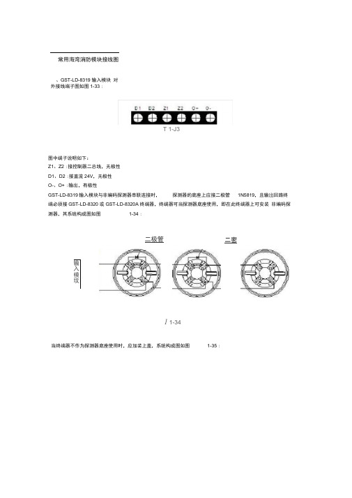
常用海湾消防模块接线图、GST-LD-8319 输入模块对外接线端子图如图1-33 :T 1-J3图中端子说明如下:Z1、Z2 :接控制器二总线,无极性D1、D2 :接直流24V,无极性O-、O+ :输出,有极性GST-LD-8319输入模块与非编码探测器串联连接时,探测器的底座上应接二极管1N5819,且输岀回路终端必须接GST-LD-8320 或GST-LD-8320A 终端器,终端器可当探测器底座使用,即在此终端器上可安装非编码探测器,其系统构成图如图1-34 :二密二极管输入模坟1 1-34当终端器不作为探测器底座使用时,应加装上盖,系统构成图如图1-35 :非编码探测器 非編码探测器 缪箱器S 1 35二、GST-LD-8300 输入模块本模块的外形及结构与 GST-LD-8319 输入模块相同,安装方法也相同,其对外端子示意如图2-2921 Z2 I G图 2- 29其中:Z1、Z2 :与控制器信号二总线连接的端子I 、G :与设备的无源常开触点(设备动作闭合报警型)连接;也可通过电子编码器设置为常闭输入 模块与具有常开无源触点的现场设备连接方法如图2-30所示。
模块输入设定参数设为常开检线。
二极管二根管o O輸入模块GST-LD-S315Z\Z2E 2- 30模块与具有常闭无源触点的现场设备连接方法如图2-31所示,模块输入设定参数设为常闭检线。
--------------------------- 'Z1 Z2I G1卍苫屯忑k常耐触授现场设备5 2-31三、GST-LD-8301 输入输出模块GST-LD-8301模块的外形尺寸及结构与GST-LD-8319输入模块相同,安装方法也相同,其对外端子示意图如图2-32 :21 22 DI D2 G MG V+ MO I G COM S-其中:Z1、Z2 :接火灾报警控制器信号二总线,无极性D1、D2 : DC24V电源输入端子,无极性G、NG、V+、NO : DC24V有源输出辅助端子,出厂默认为有源输出:G和NG短接、V+和NO短接当需无源常开输出:应将G、NG、V+、NO之间的短路片断开。
W5100模块手册

温馨提示本用户手册由《泥人通信模块开发平台》开发团队编写与审核,本手册仅适用于由泥人团队开发的NiRen_W5100模块。
本手册将持续更新于泥人的博客,请各位用户持续关注,同时泥人团队将努力开发出更多适合电子开发人员、在校同学们学习的通信模块。
让我们共同努力,迎接物联网时代的到来!!目录一、泥人W5100以太网模块简介 (1)二、模块排针功能表 (1)三、W5100芯片资源介绍 (2)四、电脑调试软件安装 (3)五、调试方法 (5)1、NiRen_W5100模块接线方法 (5)2、W5100客户端模式 (5)3、W5100服务端模式 (10)4、W5100UDP模式 (13)一、泥人W5100以太网模块简介NiRen_W5100模块是一款基于WIZnet W5100芯片的以太网模块,模块集成硬件化TCP/IP 协议;支持10/100Mbps 的传输速率;支持4个独立端口同时运行;同时模块还支持3.3V 或5V 电源供电,5V 供电时还可以输出3.3V 电源,方便用户在不同的单片机系统中使用;模块与单片机系统的通讯方式是简单、方便的SPI 通信。
以下是NiRen_W5100以太网模块的简单介绍:二、模块排针功能表排针标识功能说明排针标识功能说明3.3V 3.3V 电源输入引脚5V 5V 电源输入引脚MISO SPI 主机输入从机输出引脚GND 电源地引脚MOSI SPI 主机输出从机输入引脚RST W5200硬件初始化引脚(低电平有效)SCS SPI SLAVE 选择引脚(低电平有效)INT W5200中断引脚(低电平有效)SCLKSPI 时钟引脚NC保留、悬空1117_3.3V 电源稳压芯片10uF/16V电源滤波钽电容带网络变压器、带通讯指示LED 的RJ45型网口25MHz 的无源晶体振荡器泥人电子LOGOLED 电源指示灯W5100以太网芯片模拟电源滤高频干扰电感5V/3.3V 电源、SPI 通信片选、时钟、数据输入、数据输出、中断输出、复位输入排针预留两个安装孔,供以后用三、W5100芯片资源介绍W5100是一种款多功能的单片网络接口芯片,内部集成有10/100以太网控制器,主要应用于高集成、高稳定、高性能和低成本的嵌入式系统中。
ioThinx 4500 (45M) 模块系列用户手册说明书

ioThinx 4500 (45M) Module SeriesUser’s ManualEdition 1.0, November 2018/product© 2018 Moxa Inc. All rights reserved.ioThinx 4500 (45M) Module SeriesUser’s ManualThe software described in this manual is furnished under a license agreement and may be used only in accordance withthe terms of that agreement.Copyright Notice© 2018 Moxa Inc. All rights reserved.TrademarksThe MOXA logo is a registered trademark of Moxa Inc.All other trademarks or registered marks in this manual belong to their respective manufacturers.DisclaimerInformation in this document is subject to change without notice and does not represent a commitment on the part of Moxa.Moxa provides this document as is, without warranty of any kind, either expressed or implied, including, but not limited to, its particular purpose. Moxa reserves the right to make improvements and/or changes to this manual, or to the products and/or the programs described in this manual, at any time.Information provided in this manual is intended to be accurate and reliable. However, Moxa assumes no responsibility for its use, or for any infringements on the rights of third parties that may result from its use.This product might include unintentional technical or typographical errors. Changes are periodically made to the information herein to correct such errors, and these changes are incorporated into new editions of the publication.Technical Support Contact Information/supportMoxa AmericasToll-free: 1-888-669-2872 Tel: +1-714-528-6777 Fax: +1-714-528-6778Moxa China (Shanghai office) Toll-free: 800-820-5036Tel: +86-21-5258-9955 Fax: +86-21-5258-5505Moxa EuropeTel: +49-89-3 70 03 99-0 Fax: +49-89-3 70 03 99-99Moxa Asia-PacificTel: +886-2-8919-1230 Fax: +886-2-8919-1231Moxa IndiaTel: +91-80-4172-9088 Fax: +91-80-4132-1045Safety SymbolsNOTE Indicates a potential malfunction which, if not avoided, however, will not result in damage to property. INFORMATION This information is important for preventing errors.Table of Contents1.Preface .............................................................................................................................................. 1-1Revision History ................................................................................................................................. 1-2 Relevant Models ................................................................................................................................. 1-2 Package Checklist ............................................................................................................................... 1-2 How to Use This Device ....................................................................................................................... 1-2 Safety Precautions .............................................................................................................................. 1-3 Additional Resources ........................................................................................................................... 1-4 2.Product Overview .............................................................................................................................. 2-1Technical Data.................................................................................................................................... 2-2 Common Specifications ................................................................................................................ 2-245MR-1600 Specifications ............................................................................................................ 2-245MR-1601 Specifications ............................................................................................................ 2-245MR-2404 Specifications ............................................................................................................ 2-345MR-2600 Specifications ............................................................................................................ 2-345MR-2601 Specifications ............................................................................................................ 2-345MR-2606 Specifications ............................................................................................................ 2-345MR-3800 Specifications ............................................................................................................ 2-445MR-3810 Specifications ............................................................................................................ 2-445MR-6600 Specifications ............................................................................................................ 2-545MR-6810 Specifications ............................................................................................................ 2-545MR-7820 Specifications ............................................................................................................ 2-5 Appearance ........................................................................................................................................ 2-6 Front View .................................................................................................................................. 2-6Physical Dimensions .................................................................................................................... 2-6 LED Indicators .................................................................................................................................... 2-7 3.Hardware Installation ....................................................................................................................... 3-1Wiring I/O ......................................................................................................................................... 3-2 I/O Terminal Blocks ..................................................................................................................... 3-245MR-1600 (-T) Wiring Guide ....................................................................................................... 3-345MR-1601 (-T) Wiring Guide ....................................................................................................... 3-445MR-2404 (-T) Wiring Guide ....................................................................................................... 3-545MR-2600 (-T) Wiring Guide ....................................................................................................... 3-645MR-2601 (-T) Wiring Guide ....................................................................................................... 3-745MR-2606 (-T) Wiring Guide ....................................................................................................... 3-845MR-3800 (-T) Wiring Guide ....................................................................................................... 3-945MR-3810 (-T) Wiring Guide ..................................................................................................... 3-1045MR-6600 (-T) Wiring Guide ..................................................................................................... 3-1145MR-6810 (-T) Wiring Guide ..................................................................................................... 3-1245MR-7820 (-T) Wiring Guide ..................................................................................................... 3-13 Mounting the Module ......................................................................................................................... 3-14 Installing the I/O Module on the DIN Rail ..................................................................................... 3-14Unmounting the I/O Module from the DIN Rail .............................................................................. 3-151PrefaceIn this document, we explain the scope of and how to use this document.The following topics are covered in this chapter:❒Revision History❒Relevant Models❒Package Checklist❒How to Use This Device❒Safety Precautions❒Additional ResourcesRevision HistoryVersion Change DateV1.0 First Release 2018-11-09Relevant ModelsThis document applies to the following 45M modules:Model Name Features Operating Temp.45MR-1600 16 DIs, 24 VDC, PNP -20 to 60°C45MR-1600-T 16 DIs, 24 VDC, PNP -40 to 75°C45MR-1601 16 DIs, 24 VDC, NPN -20 to 60°C45MR-1601-T 16 DIs, 24 VDC, NPN -40 to 75°C45MR-2404 4 relays, form A -20 to 60°C45MR-2404-T 4 relays, form A -40 to 75°C45MR-2600 16 DOs, 24 VDC, sink -20 to 60°C45MR-2600-T 16 DOs, 24 VDC, sink -40 to 75°C45MR-2601 16 DOs, 24 VDC, source -20 to 60°C45MR-2601-T 16 DOs, 24 VDC, source -40 to 75°C45MR-2606 8 DIs, 24 VDC, PNP; 8 DOs, 24 VDC, source -20 to 60°C45MR-2606-T 8 DIs, 24 VDC, PNP; 8 DOs, 24 VDC, source -40 to 75°C45MR-3800 8 AIs, 0 to 20 mA or 4 to 20 mA -20 to 60°C45MR-3800-T 8 AIs, 0 to 20 mA or 4 to 20 mA -40 to 75°C45MR-3810 8 AIs, -10 to 10 V or 0 to 10 V -20 to 60°C45MR-3810-T 8 AIs, -10 to 10 V or 0 to 10 V -40 to 75°C45MR-6600 6 RTDs -20 to 60°C45MR-6600-T 6 RTDs -40 to 75°C45MR-6810 8 TCs -20 to 60°C45MR-6810-T 8 TCs -40 to 75°C45MR-7820 potential distribution module -20 to 60°C45MR-7820-T potential distribution module -40 to 75°CPackage ChecklistThe following items are in the product package.• 1 x 45M module• 1 x quick installation guide (printed)• 1 x warranty cardHow to Use This Device45M modules cannot be used as standalone devices. The modules must be used with an ioThinx 45xx Series adapter. Refer to the ioThinx 45xx Series User’s Manual for details.Safety PrecautionsObserve the following safety precautions when installing or using the devices discussed in this document:Additional ResourcesRefer to following documents for additional information.•Datasheets for the following products:ioThinx 4510 SeriesioThinx 4500 Series (45MR) Modules•User’s Manual for the following product:ioThinx 4510 Series2Product OverviewIn this chapter, we give an overview of each of the 45M modules.The following topics are covered in this chapter:❒Technical DataCommon Specifications45MR-1600 Specifications45MR-1601 Specifications45MR-2404 Specifications45MR-2600 Specifications45MR-2601 Specifications45MR-2606 Specifications45MR-3800 Specifications45MR-3810 Specifications45MR-6600 Specifications45MR-6810 Specifications45MR-7820 Specifications❒AppearanceFront ViewPhysical Dimensions❒LED IndicatorsioThinx 4500 (45M) Module Series Product Overview Technical DataCommon SpecificationsPhysical CharacteristicsConnector: Removable Terminal blockWiring: 18 to 24 AWGDimensions: 19.5 x 99.0 x 60.5 mm (0.77 x 3.90 x 2.38 in)Installation: DIN-rail mountingEnvironmental LimitsOperating Temperature:Standard Models: -20 to 60°C (-4 to 140°F)Wide Temp. Models: -40 to 75°C (-40 to 167°F)45MR-1600 SpecificationsInput/Output InterfaceDigital Input Channels: 16Isolation: 3k VDC or 2k VrmsDigital InputsSensor Type:Dry ContactWet Contact (PNP)Dry Contact:On: short to FP+Off: openWet Contact (DI to FP-):On: 10 to 30 VDCOff: 0 to 3 VDCI/O Mode: DI or event counterNote: Only the first 4 channels support event counter mode.45MR-1601 SpecificationsInput/Output InterfaceDigital Input Channels: 16Isolation: 3k VDC or 2k VrmsDigital InputsSensor Type:Dry ContactWet Contact (NPN)Dry Contact:On: short to FP-Off: openWet Contact (DI to FP+):On: 10 to 30 VDCOff: 0 to 3 VDCI/O Mode: DI or event counterNote: Only the first 4 channels support event counter mode.45MR-2404 SpecificationsInput/Output InterfaceRelay Channels: 4Isolation: 3k VDC or 2k VrmsRelaysType: Form A (N.O.) power relayContact Current Rating: Resistive load: 2 A @ 30 VDC, 250 VACContact Resistance: 100 milli-ohms (max.)Initial Insulation Resistance: 1000 mega-ohms (min.) @ 500 VDCI/O Mode: Relay45MR-2600 SpecificationsInput/Output InterfaceDigital Output Channels: 16Isolation: 3k VDC or 2k VrmsDigital OutputsI/O Type: SinkVoltage: 12/24 VDCCurrent Rating: 500 mA per channelOver-Voltage Protection: 45 VDCShort-Circuit Protection: SupportedOver-Temperature Shutdown: 175°C (typical), 150°C (min.)I/O Mode: DO or pulse outputNote: Only the first 4 channels support pulse output mode.45MR-2601 SpecificationsInput/Output InterfaceDigital Output Channels: 16Isolation: 3k VDC or 2k VrmsDigital OutputsI/O Type: SourceVoltage: 12/24 VDCCurrent Rating: 500 mA per channelOver-Voltage Protection: 45 VDCShort-Circuit Protection: SupportedOver-Temperature Shutdown: 175°C (typical), 150°C (min.)I/O Mode: DO or pulse outputNote: Only the first 4 channels support event counter mode.45MR-2606 SpecificationsInput/Output InterfaceDigital Input Channels: 8Digital Output Channels: 8Isolation: 3k VDC or 2k VrmsDigital InputsSensor Type:Dry ContactWet Contact (PNP)Dry Contact:On: short to FP+Off: openWet Contact (DI to FP-):On: 10 to 30 VDCOff: 0 to 3 VDCI/O Mode: DI or event counterNote: Only the first 2 channels support event counter mode.Digital OutputsI/O Type: SourceVoltage: 12/24 VDCCurrent Rating: 500 mA per channelOver-Voltage Protection: 45 VDCShort-Circuit Protection: SupportedOver-Temperature Shutdown: 175°C (typical), 150°C (min.)I/O Mode: DO or pulse outputNote: Only the first 2 channels support event counter mode. 45MR-3800 SpecificationsInput/Output InterfaceAnalog Input Channels: 8Isolation: 3k VDC or 2k VrmsAnalog InputsI/O Type: DifferentialInput Impedance: 120 ohmsI/O Mode: CurrentInput Range:0 to 20 mA4 to 20 mA4 to 20 mA (with burn-out detection)Resolution: 16 bits45MR-3810 SpecificationsInput/Output InterfaceAnalog Input Channels: 8Isolation: 3k VDC or 2k VrmsDigital OutputsI/O Type: DifferentialInput Impedance: 10 mega-ohms (min.)Protection:Fault and over-voltage protection:-35 to +35 VDC (power off)-25 to +30 VDC (power on)I/O Mode: VoltageInput Range:±10 VDC0 to 10 VDCResolution: 16 bits45MR-6600 SpecificationsInput/Output InterfaceRTD Channels: 6Isolation: 3k VDC or 2k VrmsDigital OutputsInput Type:PT50, PT100, PT200, PT500 (-200 to 850°C)PT1000 (-200 to 350°C)JPT100, JPT200, JPT500 (-200 to 640°C)JPT1000 (-200 to 350°C)NI100, NI200, NI500 (-60 to 250°C)NI1000 (-60 to 150°C)NI120 (-80 to 260°C)Resistance of 310, 620, 1250, and 2200 ohmsInput Impedance: 625 kilo-ohms (min.)Resolution: 0.1°C or 0.1 ohm45MR-6810 SpecificationsInput/Output InterfaceThermocouple Channels: 8Isolation: 3k VDC or 2k VrmsDigital OutputsSensor Type: J, K, T, E, R, S, B, NMillivolt Type:±19.532 mV±39.062 mV±78.126 mVInput Impedance: 1 mega-ohms (min.)Resolution: 16 bits45MR-7820 SpecificationsInput/Output InterfaceVoltage Output Channels: 16Isolation: 3k VDC or 2k VrmsNote:Field Power 12/24 VDC: 8 channelsField Power 0 VDC: 8 channelsAppearance Front ViewPhysical DimensionsUnit: mm (in)LED IndicatorsLabelUsage No. of LEDs LED Color DescriptionStatus Status 1 GreenSteady on: Module ReadySlow blinking: Booting up, module mismatch, orinstalled incorrectlyFast blinking: LocatingRedSteady on: Module errorSlow blinking: Firmware is upgradingFast blink: Safe mode (output modules only)DI0, DI1, DI2… DI 1 of each Green Steady on: Channel onOff: Channel off or no counter/pulse signalDO0, DO1, DO2… DO 1 of each Green Steady on: Channel onOff: Channel off or no counter/pulse signalRLY0, RLY1, RLY2… Relay 1 of each Green Steady on: Channel onOff: Channel off or no counter/pulse signalAI0, AI1, AI2… AI 2 of each Green Steady on: Channel enabledRed Steady on: Burn out & wire off when current modeTCx TC 2 of each Green Steady on: Channel enabledRed Steady on: Burn out & wire off when current modeRTD0, RTD2, RTD3… RTD 2 of each Green Steady on: Channel enabledRed Steady on: Burn out & wire off when current mode3Hardware InstallationIn this chapter, we describe how to install the 45M modules.The following topics are covered in this chapter:❒Wiring I/OI/O Terminal Blocks45MR-1600 (-T) Wiring Guide45MR-1601 (-T) Wiring Guide45MR-2404 (-T) Wiring Guide45MR-2600 (-T) Wiring Guide45MR-2601 (-T) Wiring Guide45MR-2606 (-T) Wiring Guide45MR-3800 (-T) Wiring Guide45MR-3810 (-T) Wiring Guide45MR-6600 (-T) Wiring Guide45MR-6810 (-T) Wiring Guide45MR-7820 (-T) Wiring Guide❒Mounting the ModuleInstalling the I/O Module on the DIN RailUnmounting the I/O Module from the DIN RailWiring I/OI/O Terminal BlocksWire range: 18 to 24 AWGWire strip length: 9 to 10 mmUnit: mm (in.)Description: 16 DIs, 24 VDC, PNP or dry contact Single Channel (Dry Contact):Single Channel (PNP):All Channels (PNP):Description: 16 DIs, 24 VDC, NPN or dry contact Single Channel (Dry Contact):Single Channel (NPN):All Channels (NPN):Description: 4 Relays, form ASingle Channel (Resistive Load):Single Channel (Inductive Load):All Channels:NOTE To avoid over current damage, fuse is recommended.Description: 16 DOs, 24 VDC, sinkSingle Channel:All Channels:NOTE We recommend using a fuse to avoid damage from current spikes.Description: 16 DOs, 24 VDC, sourceSingle Channel:All Channels:NOTE We recommend using a fuse to avoid damage from current spikes.Description: 8 DIs, 24 VDC, PNP or dry contact, 8 DOs, 24 VDC, sourceSingle Channel (DI dry contact/DI PNP/DO source):All Channels:NOTE We recommend using a fuse to avoid damage from current spikes.Description: 8 AIs, 0 to 20 mA or 4 to 20 mA Single Channel (2-wire/3-wire/4-wire):All Channels:Description: 8 AIs, -10 to 10 V or 0 to 10 V Single Channel (3-wire/4-wire):All Channels:Description: 6 RTDsSingle Channel (2-wire/3-wire/4-wire):All Channels:Description: 8 TCsSingle Channel (TC Sensor/Voltage Source):All Channels:Description: Potential distribution module Single Channel:All Channels:Mounting the ModuleTake the following steps to mount the device on or unmount the device from a DIN rail.Installing the I/O Module on the DIN RailStep 1: Align the I/O module side by side with the head/CPU module, making sure that the upper and lower rails are hooked together.Step 2: Align the I/O module side by side with the network module and then push the I/O module until it touches the DIN-rail. Next, apply more force until the module clips to the DIN-rail.NOTEAfter the module is firmly attached to the DIN-rail, the module connections to the internal bus will beestablished.INFORMATION With the I/O module inserted in place, the internal bus will establish a connection through the adjacent module(s).Unmounting the I/O Module from the DIN RailStep 1: Use your finger to lift the release tab on the lower part of the module.Step 2: Push the top of the release tab to latch it, and then pull the module out.NOTE Electrical connections for the internal bus will be disconnected when the I/O module is removed.。
DW-J31-0016无线IO模块说明书
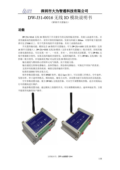
DW-J31-0016无线IO模块说明书(16路开关量输出)功能DW-J31-0016无线IO模块用于开关量信号的无线传输及控制,其嵌入高速单片机,并采用最新高性能射频芯片,采用可靠的传输机制,发射功率最大500mw,可视环境下通信距离可达2700M以上。
用于代替有线的开关量传输,具有工业级的品质。
开关量传输功能。
模块包含16路的开关量输出,可与DW-J31-1600无线IO模块(支持16路开关量输入)、DW-J31-0808无线IO模块(支持8路开关量输入)配合使用。
控制其输出继电器的状态。
可以实现一对一、一对多、多对一、多对多的灵活配置。
可与DW-R01无线中继器配合使用,实现无线传输的多级转发,延展传输距离。
可与DW-MC1无线RTU(监控器)配合使用,在电脑或是PLC对远程无线IO模块进行控制。
输出通道与模块核心控制单元电气隔离,抗干扰能力强。
输出通道支持继电器输出、晶体管输出、固态继电器输出,可满足不同客户的需求。
支持冲突检测及重传机制,确保无线传输的可靠性。
标准的DIN35导轨安装方式。
软件参数设置功能。
使用RFSET软件,通过Uart接口,可以设置工作频点、空中速率、发射功率、串口速率和格式、模块地址、触发方式等。
该设置功能可实现复杂的无线连接。
空中参数设置功能。
配合DW-MC1无线监控器,可以空中调整模块参数,适合对现场运行中的模块进行维护。
快速参数设置功能。
通过模块上的拨码开关,可以调整模块频点、速率和地址等,方便不能使用电脑的客户操作。
应用远程开关如下图所示,远程开关SW2将始终与本地开关SW1保持一致的状态。
一对多控制如下图所示,模块1的开关SW1-1可远程控制模块2的开关SW2-1;模块1的开关SW1-2可远程控制模块2的开关SW3-1;模块1的开关SW1-3可远程控制模块4的开关SW4-1. 模块1是DW-J31-1600,模块2、3、4可以是DW-J31-0016(16路开关量输出)或是DW-J31-0808(8路开关量输出)多对多控制如下图所示,模块1的开关可远程控制模块3、4的继电器输出;同时模块2的开关可远程控制模块3、4的继电器输出。
XC03-W4DI 说明书
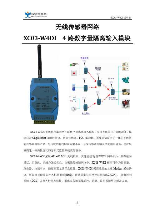
无线传感器网络XC03-W4DI 4路数字量隔离输入模块XC03-W4DI无线传感器网络4路数字量隔离输入模块,实现无线遥控、遥测功能。
模块自带ChipBeeNet自组网协议,是集传感器、I/O、低功耗、无线通信技术于一体的无线智能传感器网络产品。
与传统的有线解决方案不同,无线传感器网络灵活的组网能力,使扩展或构建一种高性价比的分布式监控系统变得容易。
XC03-W4DI采用433/470 MHz无线频率,支持星型/树型/MESH网络拓扑,具有组网灵活,距离远,穿透力强等优点。
在无线传感器网络中,XC03-W4DI模块可作为协调器、路由器、终端节点,通过配置工具任意设置。
XC03-W4DI采用流行的工业Modbus通信协议,可以直接配接各种人机界面屏(HMI)、数据采集与监视控制系统(SCADA)、分散控制系统(DCS)以及各种组态软件,形成完备的无线遥控、遥测、监控系统整体解决方案。
一、 产品特性◆4路IO隔离输入,无线传感器网络组网传输,实现无线遥控、遥测。
◆全工业设计,供电电源、信号输入输出、RS485接口在电气上实现互为隔离,有效抑制工业现场各类串模和共模干扰,保证了工作可靠性和数据精准度。
◆自带ChipBeeNet 无线自组网协议,支持星型/树型/MESH网络拓扑,组网灵活,性能可靠稳定。
◆支持Modbus RTU通信协议,可以直接配接HMI、SCADA、DCS以及各种组态软件。
◆模块内置DC24V 40mA辅助电源,具有短路保护功能,兼容干、湿接点输入。
◆模块在无线网络中可作为协调器、路由器、终端节点,通过配置工具任意设置。
◆数据采集灵活:定时主动上报或上位机查询二、 技术参数开关量输入◆4路有源(湿接点)或无源(干接点)输入◆有源(湿接点)输入时极性自适应◆内置DC24V 40mA辅助电源,具有短路保护功能入◆1500Vdc隔离(可定制为3000Vdc)◆输入电阻:5KOhm◆输入电平:干接点: 逻辑 “0”:接地(GND)逻辑 “1”:开路湿接点: 逻辑 “0”:0 - 2V max逻辑 “1”:4 - 36V通信接口◆物理接口:RS485◆通讯协议:MODBUS RTU:◆波特率:1200、2400、4800、9600、19200、38400、57600、115200 bps◆校验方式:无校验、奇校验、偶校验◆保护功能:防雷、抗干扰设计无线特性◆自主研发的ChipBeeNet无线自组网协议,支持星型/树型/MESH网络拓扑◆无线频率: 433/470频段(出厂前确定中心频率)◆调制方式:2GFSK◆无线信道:20个◆射频数据速率:10Kbps◆最大发射功率:≤100mW(20dBm)◆峰值电流:80mA◆信道检测:CSMA/CA◆接收灵敏度:-117dBm◆网络拓扑:星型/树型/MESH网◆无线通信距离:≤1000米(室外可视,3 dBi天线)◆网络节点容量:最大32个节点(路由节点+终端节点)◆无线距离扩展: 最多5 跳◆节点功能:协调器、路由器、终端设备可任意配置◆天线连接:外置SMA 天线电源输入◆外接电源输入:DC9~36 宽电压输入,具有防反接、防浪涌保护功能◆设备功耗:<3W◆保护功能:防雷、防反接外形结构◆模块结构:亚当模块,10位可拔插端子(2EDG-5.08-10P 弯针)◆安装方式:DIN导轨安装◆外形尺寸: 107.5mm x 72mm x 26mm(不含端子和导轨座)116.5mm x 72mm x 41.5mm(含端子、天线座和导轨座))◆模块重量:约200g环境◆工作温度:-25~+70°C (外接电源)0~+50°C (电池供电)◆工作湿度:20~95%RH(不结露)◆存储环境温度:-20~+85°C◆存储环境湿度:0~95%RH(不结露)三、 外形尺寸和安装示意图图一、模块尺寸图图二、安装示意图四、 安装注意事项1.天线与接收装置的天线尽量保证在同一平面内。
SIWAREX WP351 HF 轻量级准确称重模块的中文名称说明书
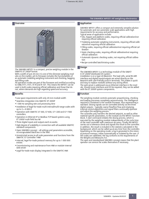
OverviewTM SIWAREX WP351 HF weighing electronicsTM SIWAREX WP351 HF weighing electronics1The SIWAREX WP351 is a compact, precise weighing module in the SIMATIC ET 200SP format.With a width of just 20 mm it is one of the slimmest weighing modules on the market, yet its firmware includes the functionalities of an automatic totalizing weighing instrument and checking, bagging and filling scale.All operation modes are part of the firmware and certified according to OIML R-51, R-61, R-76 and R-107. This means the WP351 can be used in both scales requiring official calibration and those that do not, where demands are high regarding speed and accuracy.•Low space requirements with only 20 mm module width •Seamless integration into SIMATIC ET 200SP •1 000 Hz sampling rate und processing time•Installation of legal-for-trade multi-interval/multi-range scales with up to 3 × 6 000 d•Operation with SIMATIC S7-300, S7-400, S7-1200 and S7-1500controllers•Operation in Ethernet IP or Modbus TCP-based systems using ET 200SP multi-field bus IM•Three digital inputs and outputs each ex works•High degree of scalability in connection with all available SIMATIC standard components•Open SIWAREX concept – all settings and parameters accessible,no encapsulated black box in the field•Unrestricted access to all scale parameters and functions from theSIMATIC S7 Controller / HMI•Internal, legal-for-trade protocol memory for up to 1 000 000entries•Commissioning and maintenance from HMI or module-internal web server•Legal-for-trade main display integrated in the SIMATIC HMISIWAREX WP351 offers a compact and extremely versatile solutionfor automatic and non automatic scale applications with high requirements for accuracy and performance. Typical areas of application include:•Silo, hopper and platform scales, requiring official calibration/not requiring official calibration•Totalizing automatic weighing instruments, requiring official calibration/not requiring official calibration•Filling scales, requiring official calibration/not requiring official calibration•Static checking scales, requiring official calibration/not requiring official calibration•Automatic dynamic checking scales, not requiring official calibration•Recipe-controlled batch/mixing scalesThe SIWAREX WP351 is a technology module of the SIMATIC ET 200SP distributed I/O system.Installation is on a type U0 BaseUnit. The load cells, serial RS 485interface and digital inputs/outputs are wired directly on theBaseUnit with user-friendly push-in terminals. This makes is quick and easy to replace modules without any wiring effort.The web server is addressed via an Ethernet interface in the module. Should more interfaces and I/O be required, they can be added with the ET 200SP system components.The weighing module controls automatic proportioning, checking and loading processes completely autonomously. The intelligence required is contained in the module firmware, thus representing a standard. Dosing signals can be controlled directly via the three digital outputs – typically coarse flow/fine flow and emptying.Internal control algorithms and signal filters continually optimize and adjust the weighing process.The controller only transfers the desired setpoint, as well as other material-specific parameters, to the module via the WP351 function block. A start command initiates the dosing process, which isexecuted by the weighing module independently of the cycle time of the main controller with maximum accuracy. Finally the WP351carries out a tolerance check and signals the result to the controller.In addition, the result is included in the statistics calculated in the background, which can be called up at any time from the controller.Depending on the operating mode, a log is generated in the internal protocol memory, either automatically or initiated by the user. If the scales are calibrated, the log conforms to the requirements of the Weights and Measures Act.The open and standardized SIWAREX concept means that the plant operator can service the scales themselves if necessary.SIWAREX · Updated 8/2023© Siemens AG 2023TM SIWAREX WP351 HF weighing electronics2SIWAREX · Updated 8/2023TM SIWAREX WP351 HF weighing electronics3* At a height of more than 2 000 m above sea level, a derating of the ambient temperature of -1 °C / 100 m has to be adhered to. The maximum permissible height is 5 000 meters above sea level. At over 0.6 A total current of the digital outputs DQ, a derating of the ambient temperature of -1 °C per 100 mA has to be adhered to. The max. permissible total current is 1.5 A.SIWAREX · Updated 8/2023。
M5S模块化器件CX通信及控制接口类模块说明书
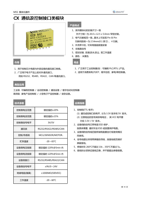
CX通信及控制接口类模块产品特点作用用途典型应用工业级:可编程控制器/运动控制器/通信设备/楼宇自动化控制器商用级:家电产品控制板/小型电子产品控制器/安防设备。
技术参数应用指南控制侧电压范围额定值的±20%控制侧电流范围额定值的±15%控制侧信号电平3V/5V通讯类RS232/RS422/RS485/CAN 控制/传感类MCU/SENSOR/MOTOR..贮存温度-20~65℃设备侧电压极限额定值的120%@5min 内设备侧电流极限额定值的120%@5min 内设备侧接口RS232/RS485/RS422/CAN设备侧信号电平±9V/0~24V 绝缘电阻(隔离)≥1000MΩ(500VDC)工作温度-20~60℃1、系列模快化的封裝尺寸一致外尺寸统一为20.0x 12.5x 5.0mm 窄型封装。
2、电气引脚规范一致,,基本上可实现Pin 对Pin引脚间距统一为2.54mm(0.1英寸),4引脚。
3、外壳带卡扣,可采用插座拔插安装4、非隔离信号5、密封封装,防潮,防水,防尘,宽工作温度6、颜色:米黄色1、用于控制芯片电路与外部设备的通讯接口转换。
2、广泛用于电子产品上的对外通讯接口。
例如RS232、RS485、RS422、CAN 等通讯接口。
压力、流量、速度、张力信号检测。
1、控制侧(TTL 电平):(1)通讯或控制口的电平,分为3.3V 版本和5V 版本。
(2)注意相应的型号其供电电压,其VCC 电平要对应3.3V /5V 版本。
2、设备侧的信号已带有弱ESD 保护,按具体需要,最好外加ESD 或放雷保护电路。
3、设备侧的信号线匹配终端电阻要自行视使用情况而使用。
4、信号线建议采用带屏蔽的寻线,按接地规范做好屏蔽接地。
5、焊接时在260℃不超过10s,350℃不超过5s。
6、接线时必须保证接线正确,并不能超出参数极限。
1、广泛用于工业控制器(如:可编程PLC/RTU..)产品。
罗克韦尔 Compact 5000 I O 数字量模块 说明书

基于 EtherNet/IP 的连接 . . . . . . . . . . . . . . . . . . . . . . . . . . . . . . . . . . . 56 使用 External Means 时连接的其他注意事项 . . . . . . . . . . . . . . . . 57 受限操作 . . . . . . . . . . . . . . . . . . . . . . . . . . . . . . . . . . . . . . . . . . . . . . . . . . . . . . . 58 安全模块特定注意事项 . . . . . . . . . . . . . . . . . . . . . . . . . . . . . . . . . . . . . . . . 59 整体系统安全功能 . . . . . . . . . . . . . . . . . . . . . . . . . . . . . . . . . . . . . . . . . 60 单通道或双通道模式 . . . . . . . . . . . . . . . . . . . . . . . . . . . . . . . . . . . . . . . 60 与安全控制器结合使用 . . . . . . . . . . . . . . . . . . . . . . . . . . . . . . . . . . . . 61 确定符合性 . . . . . . . . . . . . . . . . . . . . . . . . . . . . . . . . . . . . . . . . . . . . . . . . 61
ZM32-U 系列 ZigBee 模块数据手册说明书
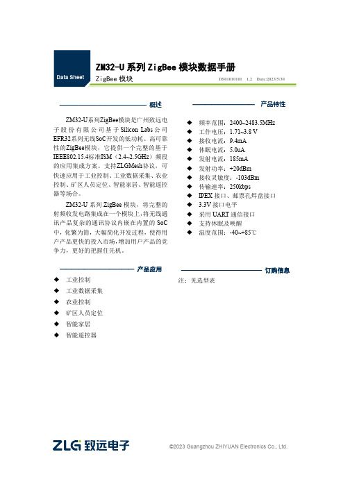
©2023Guangzhou ZHIYUAN Electronics Co.,Ltd.ZM32-U 系列ZigBee 模块数据手册ZigBee 模块DS01010101 1.2Date:2023/5/30——————————————概述ZM32-U 系列ZigBee 模块是广州致远电子股份有限公司基于Silicon Labs 公司EFR32系列无线SoC 开发的低功耗、高可靠性的ZigBee 模块,它提供一个完整的基于IEEE802.15.4标准ISM (2.4~2.5GHz )频段的应用集成方案。
支持ZLGMesh 协议,可快速应用于工业控制、工业数据采集、农业控制、矿区人员定位、智能家居、智能遥控器等场合。
ZM32-U 系列ZigBee 模块,将完整的射频收发电路集成在一个模块上,将无线通讯产品复杂的通讯协议内嵌在内置的SoC 中,化繁为简,大幅简化开发过程,使得用户产品更快的投入市场,增加用户产品的竞争力,更好的把握住先机。
————————————产品应用◆ 工业控制◆ 工业数据采集◆ 农业控制◆ 矿区人员定位◆ 智能家居◆ 智能遥控器—————————————订购信息注:见选型表——————————产品特性◆频率范围:2400~2483.5MHz ◆工作电压:1.71~3.8V ◆接收电流:9.4mA ◆休眠电流:5.0uA ◆发射电流:185mA ◆发射功率:+20dBm ◆接收灵敏度:-103dBm ◆传输速率:250kbps◆IPEX 接口、邮票孔焊盘接口◆ 3.3V 接口电平◆采用UART 通信接口◆支持休眠及唤醒◆温度范围:-40~+85℃修订历史目录1.产品简介 (1)1.1概述 (1)1.2产品命名规则 (1)1.3产品选型 (2)2.外观尺寸 (3)3.引脚定义 (4)4.电气参数 (7)4.1工作条件 (7)4.2工作环境 (7)4.3产品功耗 (7)5.射频参数 (8)6.生产指导 (9)6.1推荐生产回流温度曲线 (9)6.2推荐生产回流温度时间对照表 (9)7.硬件设计参考 (10)7.1最小系统 (10)7.2推荐系统 (10)7.3电源设计 (11)7.4RF设计 (11)7.4.1外接天线使用指导 (11)7.4.2邮票孔天线接口设计指导 (11)7.4.3外接连接器参考尺寸图 (12)7.4.4PCB布板注意事项 (12)8.包装信息 (14)9.免责声明 (15)1.产品简介1.1概述ZM32-U系列ZigBee模块是广州致远电子股份有限公司基于ZM32系列ZigBee模块推出的升级版本,具备更优异的综合性能。
XW-WXZ3消谐装置说明书解析

XW-WXZ3微机消谐装置用户手册- 1 -山西鑫稳电器有限公司目录1 概述 (1)2 功能及特点 (3)3 技术参数 (3)4 工作原理 (4)5 面板说明 (5)6 操作说明 (6)7 通信 (8)8 安装 (10)9 试验说明 (12)10 运输及贮存 (13)11 质量保证及服务 (13)12 订货须知 (13)- 2 -1概述在电力系统中,铁磁谐振频繁发生,谐振时会产生过电压,严重威胁系统安全。
铁磁谐振过电压可以在3~220千伏的任何系统中发生,特别是在35千伏及以下的电网中,几乎所有的内部过电压事故均由铁磁谐振引起。
铁磁谐振引起的过电压持续时间长,甚至可能长期存在。
在分频谐振时,一般过电压并不高,但是PT的电流大,易使PT过热而爆炸;基波和倍频谐振时,一般电流不大,但是过电压很高,常使设备绝缘损坏,造成恶性事故。
XW-WXZ3电力微机消谐装置是我公司研制的新型智能化电力谐振消除装置,使用简单方便,无需维护,能迅速地消除各种频率的铁磁谐振,准确率高。
同时可根据用户需要将相关信息打印或通过通信接口传给上级监控系统,适用于无人值守变电站。
2功能及特点➢适用于配电网各种电压等级。
- 3 -➢最多可监测四段母线。
➢迅速消除三分频、二分频、工频以及三倍频等特征频率的铁磁谐振。
➢能区分外部过电压、铁磁谐振和单相接地。
➢采用大功率、无触点消谐元件,消谐迅速、可靠。
➢提供一组无源报警节点。
➢故障发生时,能显示故障报告(类型、时间、电压值和频率)。
➢选配的微型打印机可以及时打印故障报告。
➢可配置通信接口将相关信息传给上级监控系统。
➢保存十条最近发生的故障信息,失电后数据不丢失。
➢具备看门狗防止死机现象发生。
➢具有完善的自检功能。
➢人机接口操作简单方便,全中文菜单,显示信息丰富直观。
➢晶闸管击穿后自动保护功能。
3技术参数3.1环境要求➢户内使用,通风应良好。
➢环境温度:-10℃~+55℃➢相对湿度:小于90%,表面无凝露。
Moxa ioThinx 4500 Series 45ML模块说明书

ioThinx4500Series(45ML)Modules45ML modules for the ioThinx4500SeriesFeatures and Benefits•Easy tool-free installation and removal•Wide operating temperature model available:-40to75°C(-40to167°F)CertificationsIntroductionThe45ML series includes serial interface modules that can be used with the ioThinx4500Series head/CPU module,which has the communication bus installed on the left side.With its unique mechanical design,hardware installation and removal can be done easily without tools,greatly reducing the amount of time required to set up and replace the modules.Easy Tool-Free Installation and RemovalThe ioThinx4500Series has a unique mechanical design that reduces the amount of time required for installation and removal.In fact,screwdrivers and other tools are not required for any part of the hardware installation,including mounting the device on a DIN-rail,as well as connecting the wiring for both communication and I/O signal acquisition.Furthermore,no tools are required to remove the ioThinx from a DIN-rail.Removing all of the modules from a DIN-rail is also easy using the latch and release tab.SpecificationsInput/Output InterfaceIsolation3k VDC or2k VrmsSerial InterfaceConnector Spring-type Euroblock terminalNo.of Ports45ML-5401Series:4Serial Standards45ML-5401Series:RS-232,RS-422,RS-485-2wBaudrate45ML-5401Series:300,600,1200,1800,2400,4800,9600,19200,38400,57600,115200bpsData Bits45ML-5401Series:7,8Stop Bits45ML-5401Series:1,2Parity45ML-5401Series:Even,None,OddFlow Control45ML-5401Series:RTS/CTS(RS-232only),XON/XOFFPull High/Low Resistor for RS-48545ML-5401Series:10kilo-ohmRS-485Data Direction Control45ML-5401Series:ADDC®(automatic data direction control)Serial SignalsRS-232TxD,RxD,RTS,CTS,GNDRS-422Tx+,Tx-,Rx+,Rx-,GNDRS-485-2w Data+,Data-,GNDPower ConsumptionSystem Power45ML-5401Series:74.1mA@12VDC45ML-5401Series:37.05mA@24VDCField Power45ML-5401Series:140.4mA@12VDC45ML-5401Series:59.8mA@24VDCPhysical CharacteristicsHousing PlasticDimensions26.4x99x65.5mm(1.04x3.9x2.58in)Weight45ML-5401Series:115g(0.254lb)Installation DIN-rail mountingWiring Serial cable,18to24AWGStrip Length Serial cable,9to10mmEnvironmental LimitsOperating Temperature Standard Models:-20to60°C(-4to140°F)Wide Temp.Models:-40to75°C(-40to167°F)Storage Temperature(package included)-40to85°C(-40to185°F)Ambient Relative Humidity5to95%(non-condensing)Altitude Up to2000m1Standards and CertificationsEMC EN55032/35EMI CISPR32,FCC Part15B Class AEMS IEC61000-4-2ESD:Contact:4kV;Air:8kVIEC61000-4-3RS:80MHz to1GHz:3V/mIEC61000-4-4EFT:Power:1kV;Signal:1kVIEC61000-4-5Surge:Power:2kV;Signal:1kVIEC61000-4-6CS:3VIEC61000-4-8PFMF1.Please contact Moxa if you require products guaranteed to function properly at higher altitudes.Shock IEC60068-2-27Vibration IEC60068-2-6DeclarationGreen Product RoHS,CRoHS,WEEEMTBFTime45ML-5401Series:916,671hrs Standards Telcordia SR332WarrantyWarranty Period5yearsDetails See /warranty Package ContentsDevice1x45ML Series product Installation Kit1x terminal block,20-pin,3.5mm Documentation1x quick installation guide1x warranty card DimensionsOrdering Information45ML-5401RS-232,RS-422,RS-485-2w4-20to60°C45ML-5401-T RS-232,RS-422,RS-485-2w4-40to75°C©Moxa Inc.All rights reserved.Updated Nov05,2020.This document and any portion thereof may not be reproduced or used in any manner whatsoever without the express written permission of Moxa Inc.Product specifications subject to change without notice.Visit our website for the most up-to-date product information.。
XL-WIFI-D01-Wifi模块详细资料

XL WIFI D01WifiXL-WIFI-D01 -Wifi模块详细资料产品型号:XL-WIFI-D01产品特性接口•双排插针式接口:HDR254M-2X4 支持波特率范围:1200~115200bps 支持硬件RTS/CTS 流控•单3.3V 供电无线•支持IEEE802.11b/g 无线标准数更高的传输性能高可达•更高的传输性能,□高可达11KB/S的发送速率简介•XL-WIFI-D01 是全新的第三代嵌入式Uart-Wifi模块产品。
•Uart-Wifi是基于Uart接口的符合wifi无线网络标准的嵌入式模块,内置无线网络协议IEEE802.11 协议栈以及TCP/IP 协议栈,能够实现用户串口数据到无线网络之间的转换。
通IEEE80211TCP/IP过Uart-Wifi模块,传统的串口设备也能轻松接入无线网络。
•XL-WIFI-D01 在前两代产品的基础上进行了全面的软硬件升级,功能更加强大,使用更加简单:• 全面支持串口透明数据传输模式,真•正实现串口的即插即用• 全新的AT+指令集,全部基于ASCII•格式,简单易懂,使用更容易• 更加完备的TCP/IP 协议栈,支持•DHCP 协议动态IP 地址分配和DNSDHCP IP•域名解析功能• 内置WEB 服务器,实现使用IE 浏览•器通过无线网络远程配置模块参•支持频率范围:2.412~2.484 GHz• 支持两种无线网络类型:支持两种无线网络类型•基础网(Infra)和自组网(Adhoc) 支持多种安全认证机制:•WEP64/WEP128/ TKIP/CCMP(AES)•WEP/WPA-PSK/WPA2-PSK• 支持快速联网• 支持无线漫游•其它• 支持多种网络协议:•TCP/UDP/ICMP/DHCP/DNS/HTTP 支持自动和命令两种工作模式支持串明传输模式 支持串口透明传输模式• 支持AT+控制指令集• 支持多种参数配置方式:•串口/WEB 服务器/无线连接•应用领域• 智能公交网络,如无线刷卡机智能公交网络如无线刷卡机 小额金融支付网络,如无线POS 机 工业设备联网,如无线传感器 物联网目录•1产品简介•2产品综述2.1技术规格2.2硬件说明2.2.1机械尺寸2.2.2外部接口2.2.3天线(选配)2232.2.4串口转接板(选配)2.2.5无线适配器(选配)2.3主要功能2.3.1连接无线网络2.3.2串口即插即用2.3.3串口命令模式2.3.4TCP/IP 协议栈234TCP/IP2.3.5灵活的参数配置2.3.6多功能GPIO2.3.7固件在线升级•3快速开始向导3.1准备工作3.2设置参数3.3开始测试33•4产品设计指南4.1硬件连接4.2工作模式4.2.1启动模式选择4214.2.2自动工作模式4.2.3命令工作模式4.3参数详细说明4.3.1无线设置参数4324.3.2网络设置参数4.3.3工作模式设置参数4.3.4高级无线设置参数4.3.5串口设置参数4.3.6透明模式设置参数4.3.7系统设置参数4.4出厂默认设置4.5典型应用范例4.5.1主动型串口设备联网4524.5.2被动型串口设备联网4.5.3广播方式的串口设备联网4.5.4无线虚拟串口4.5.5多网络连接模式•5配置管理指南5.1使用配置管理软件515.1.1简介5.1.2模块管理5.1.3配置参数5.1.4功能测试5.1.5系统信息5.1.6固件升级5.2使用WEB 服务器5.2.1查询/修改配置参数5.2.2在线固件升级5225.3使用超级终端程序•6AT+指令控制协议6.1语法说明6.1.1语法格式6.2指令集6.2.1指令列表6.2.2网络控制类6.2.3系统控制类6.2.4参数设置类6246.3例程代码6.3.1例程代码说明6.3.2命令模式下Wifi 网卡的操作流程6.3.3示例代码主要的数据结构6.3.4串口数据操作串数据操作6.3.5AT 指令返回参数解析函数6.3.6字符串操作函数6.3.7几种AT 指令发送解析示例附录常见问题与解答• AQ1:模块为何搜索不到指定的网络?Q2:模块为什么连接不上网络?Q3:模块设置为WPA/WPA2 安全模式时,为什么在复位后需要10 多秒才能响应指令或自动连上网络?Q4:模块已经显示加网成功,为什么PING 不通?:自动工作模式下为什么模块联网后总是一会儿能通一会儿又Q5:自动工作模式下,为什么模块联网后总是会儿能PING通,会儿又PING不通?Q6:自动工作模式下,为什么模块复位后没有自动联网?Q7:自动工作模式下,为什么通过串口发送到模块的数据,延迟一段时间才被发送到网络上?Q8:自动工作模式下,输入逃逸字符后为什么无法退出透明传输状态?Q9:为什么配置程序搜索不到模块?Q10:使用配置程序修改参数,为什么返回使用了禁止的操作符错误?使用配置程序修改参数为什么返回使用了禁止的操作符错误?Q11:为什么打不开WEB 服务器网页?Q12:用户设置了自身不支持的波特率,导致的再也无法连接模块该怎么办?Q13:无线连接时为什么搜索不到指定的模块?Q14:在我的使用环境下,为什么无线网络连接的质量总是很差?•附录B 文档修订记录1 产品简介•XL-WIFI-D01 是全新的第三代嵌入式Uart-Wifi模块产品。
H3-EM 模块化电子摇柄说明书
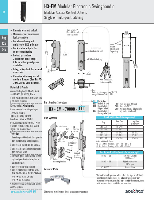
Card reader harness with connector
See Reader Connector options in table
PIN 1
PIN 3
• Local monitoring with
PIN 1: GND2 (black wire)
multi-color LED indicator
Black powder coat
100 High security DIN lock
200 Key code CH751
300 Key code RS001 (Multiple RS key codes available)
Cam Part Number (Order seperately)
Grip
control options
/H3-EM
Dimensions in millimeters (inch) unless otherwise stated
Dual Frequency
Reader
Now Available
H3-EM Modular Access Control Readers
Meet evolving security requirements
39
44.4
29
14.5
(1.7)
(1.1)
(.57)
110
113
(4.3)
(4.5)
45.2 (1.78)
14.5 (.57) 2X Ø3.5 (.14)
Mounting hole for M3 self tapping screws
Notes
*See specific Reader drawings at for compatible card types **MIFARE, MIFARE Classic, MIFARE Plus, and MIFARE DESfire are trademarks of NXP B.V. ***HID iClass is a registered trademark of HID Global
DAM-5181S 使用说明书 模拟量采集模块

DAM-5181S使用说明书模拟量采集模块(Version2.10)四川中科亿优科技有限公司w w w.z-y i y o u.c o m目录1产品简介 (1)1.1产品概述 (1)1.2技术参数 (1)1.3产品出厂默认设置 (1)1.4产品外形 (2)2接线说明 (2)2.1模块端口示意图 (2)2.2接口定义 (3)2.3供电电源 (3)2.4通信接口 (3)2.4.1RS485连接 (4)2.4.2RS232连接 (4)2.5电压模拟量输入接线 (5)3通信说明 (5)3.1主从模式 (5)3.2通信参数 (5)3.2.1通信地址 (5)3.2.2通信速率 (6)3.3MODBUS-RTU通信协议 (5)3.3.1读寄存器状态采集数据 (6)3.3.2设置设备地址 (7)3.3.3设置波特率 (7)4配置安装 (8)4.1上位机调试说明 (8)4.2模块参数配置说明 (9)4.3指示灯说明 (9)4.4产品尺寸 (9)4.5安装方式 (10)5售后服务 (11)6免责声明 (11)6.1版权 (11)6.2修改文档的权利 (11)1、产品简介1.1产品概述DAM-5181S模拟量采集模块可采集量程为0-5V/0-10V/±5V/±10V的模拟量输入信号,其他量程可以定制。
模块配置隔离RS485/隔离RS232通讯接口,采用工业标准Modbus-RTU 通信协议,可与组态软件、PLC、工业触控屏等进行组网使用,广泛应用于工业现场设备的信号采集、监控等。
电源端口和通信端口都具有防浪涌,防雷击保护,能够最大限度防止工业现场的静电和浪涌冲击。
采用标准DIN35导轨安装方式,现场安装简单方便。
1.2技术参数技术参数描述屏幕显示OLED0.96寸屏幕显示输入通道2路/4路/8路模拟量输入输入类型电压输入电压量程0~5V、0~10V、±5V、±10V(其他量程可以定制)通信接口隔离RS485/隔离RS232通信协议标准Modbus-RTU波特率1200~115200bps默认参数设备地址1;9600,8,N,1分辨率12位采集精度0.2%采样频率AD采样速率1kHz;Modbus通信更新速率<10Hz工作电压DC+8~24V通信地址1~245支持设备PLC、触摸屏、组态软件等稳定性内置看门狗,防死机保护等级电源接口有防反接保护,防浪涌,防雷击工作温度-40℃~+80℃安装方式标准DIN导轨安装外形尺寸122*72*45mm1.3产品出厂默认设置产品出厂默认设置参数为:●设备地址:1;●波特率:9600bps;●MODBUS-RTU的数据通信格式:8位数据位,1位停止位,无奇偶校验位;1.4产品外形2、接线说明2.1模块端口示意图2.2接口定义端子编号端子名称说明1VCC电源输入正极2GND电源输入负端3GND接地端4485B RS485信号B-5485A RS485信号A+6GND RS485信号接地端7232T RS232发送端8232R RS232接收端9GND RS232接地端10CANL CANL端11CANH CANH端12GND接地端13AIV1第1路模拟量输入正端14GND信号地15AIV2第2路模拟量输入正端16GND信号地17AIV3第3路模拟量输入正端18GND信号地19AIV4第4路模拟量输入正端20GND信号地21AIV5第5路模拟量输入正端22GND信号地23AIV6第6路模拟量输入正端24GND信号地25AIV7第7路模拟量输入正端26GND信号地27AIV8第8路模拟量输入正端28GND信号地2.3供电电源供电电压为8~24V DC的直流电源,需要注意接口有正负之分,输入电源的最大电压为24V,注意保持电压波动在规定的范围内,超过范围可能会造成模块电路永久性损坏。
5069 Compact I O 数字量 16 点继电器输出模块 产品目录号 5069-OW16 用
安装说明5069 Compact I/O 数字量 16 点继电器输出模块产品目录号 5069-OW165069-OW16 数字量 16 点常开型继电器输出模块用于驱动输出设备。
从 Logix5000™ 控制器和某些 5069 Compact I/O™ 输入模块状态发送至上述模块的数据用于确定 5069-OW16 模块行为。
5069 Compact I/O 模块采用生产者/消费者通信模式。
生产者/消费者通信模式是模块与其他系统设备之间的一种智能数据交换,在通信过程中,每个模块都会生成数据,而不是先被轮询。
5069 Compact I/O 系统作为 CompactLogix™ 5380 控制器系统的本地 I/O 模块,或作为 CompactLogix 5380 控制器以及其它一些 Logix5000 控制器的远程 I/O 模块。
这些模块是通过 Studio 5000 Logix Designer®应用程序进行配置的。
有关 Logix5000 控制器和 Logix Designer 应用程序版本与 5069 Compact I/O 模块兼容的更多信息,请参见其他资源 第12 页的中列出的出版物。
主题页码关于模块5安装 CompactLogix 5380 控制器系统或 5069Compact I/O 系统5所需组件5安装可拆卸端子块6安装模块7安装终端盖8对可拆卸端子块进行接线8断开电线与可拆卸端子块之间的连接8接线图9为系统供电10拆卸模块10更换模块10技术参数11其他资源125069 Compact I/O 数字量 16 点继电器输出模块ATTENTION:Read this document and the documents listed in the Additional Resources section about installation, configuration and operation of this equipment before you install, configure, operate ormaintain this product. Users are required to familiarize themselves with installation and wiring instructions in addition to requirements of all applicable codes, laws, and standards.Activities including installation, adjustments, putting into service, use, assembly, disassembly, and maintenance are required to be carried out by suitably trained personnel in accordance with applicable code of practice.If this equipment is used in a manner not specified by the manufacturer, the protection provided by the equipment may be impaired.注意:在安装、配置、操作和维护本产品前,请阅读本文档以及“其他资源”部分列出的有关设备安装、配置和操作的相应文档。
WIRL-PRO9 915MHz 低功耗无线模块说明书

Dimensions: [mm]26070562910112607056291011Cautions and Warnings:The following conditions apply to all goods within the product series of wireless connectivity of Würth Elektronik eiSos GmbH & Co. KG:General:•This electronic component is designed and developed with the intention for use in general electronic equipment.•Würth Elektronik must be asked for written approval (following the PPAP procedure) before incorporating the components into any equipment in fields such as military, aerospace, aviation, nuclear control, submarine, transportation (automotive control, train control, ship control), transportation signal, disaster prevention, medical, public information network, etc. where higher safety and reliability are especially required and/or if there is the possibility of direct damage or human injury.•Electronic components that will be used in safety-critical or high-reliability applications, should be pre-evaluated by the customer.•The component is designed and manufactured to be used within the datasheet specified values. If the usage and operation conditions specified in the datasheet are not met, the wire insulation may be damaged or dissolved.•Do not drop or impact the components, the component may be damaged.•Würth Elektronik products are qualified according to international standards, which are listed in each product reliability report. Würth Elektronik does not guarantee any customer qualified product characteristics beyond Würth Elektroniks’ specifications, for its validity and sustainability over time.•The customer is responsible for the functionality of their own products. All technical specifications for standard products also apply to customer specific products.Product specific:Soldering:•The solder profile must comply with the technical product specifications. All other profiles will void the warranty.•All other soldering methods are at the customer’s own risk.Cleaning and Washing:•Washing agents used during the production to clean the customer application might damage or change the characteristics of the component. Washing agents may have a negative effect on the long-term functionality of the product.•Using a brush during the cleaning process could break the module. Therefore, we do not recommend using a brush during the PCB cleaning process.Potting and Coating:•If the product is potted in the costumer application, the potting material might shrink or expand during and after hardening. Shrinking could lead to an incomplete seal, allowing contaminants into the component. Expansion could damage the components. We recommenda manual inspection after potting to avoid these effects.•Conformal coating may affect the product performance.Storage Conditions:• A storage of Würth Electronik products for longer than 12 months is not recommended. Within other effects, the terminals may suffer degradation, resulting in bad solderability. Therefore, all products shall be used within the period of 12 months based on the day of shipment.•Do not expose the components to direct sunlight.•The storage conditions in the original packaging are defined according to DIN EN 61760-2.•If there is a moisture sensitive component, the storage condition in the original packaging is defined according to IPC/JEDEC-J-STD-033. It is also recommended to return the component to the original moisture proof bag and reseal the moisture proof bag again.•ESD prevention methods need to be followed for manual handling and processing by machinery.Handling:•Violation of the technical product specifications such as exceeding the nominal rated current, will void the warranty.•Violation of the technical product specifications such as but not limited to exceeding the absolute maximum ratings will void the conformance to regulatory requirements.•The Edge castellation is designed and made for prototyping, i.e. hand soldering purposes only.•Non-antenna modules must be equipped with a proper antenna having specific characteristics.•The applicable country regulations and specific environmental regulations must be observed.•Do not disassemble the product. Evidence of tampering will void the warranty.These cautions and warnings comply with the state of the scientific and technical knowledge and are believed to be accurate and reliable. However, no responsibility is assumed for inaccuracies or incompleteness.All topics are described in a more detailed manner in the manual for each product.Würth Elektronik eiSos GmbH & Co. KGEMC & Inductive SolutionsMax-Eyth-Str. 174638 WaldenburgGermanyCHECKED REVISION DATE (YYYY-MM-DD)GENERAL TOLERANCE PROJECTIONMETHODGE001.0242019-07-18DIN ISO 2768-1mDESCRIPTIONWIRL-PRO9 Radio module 915MHzlow power ORDER CODE2607056291011BUSINESS UNIT STATUS PAGEImportant NotesThe following conditions apply to all goods within the product range of Würth Elektronik eiSos GmbH & Co. KG:1. General Customer ResponsibilitySome goods within the product range of Würth Elektronik eiSos GmbH & Co. KG contain statements regarding general suitability for certain application areas. These statements about suitability are based on our knowledge and experience of typical requirements concerning the areas, serve as general guidance and cannot be estimated as binding statements about the suitability for a customer application. The responsibility for the applicability and use in a particular customer design is always solely within the authority of the customer. Due to this fact it is up to the customer to evaluate, where appropriate to investigate and decide whether the device with the specific product characteristics described in the product specification is valid and suitable for the respective customer application or not.2. Customer Responsibility related to Specific, in particular Safety-Relevant ApplicationsIt has to be clearly pointed out that the possibility of a malfunction of electronic components or failure before the end of the usual lifetime cannot be completely eliminated in the current state of the art, even if the products are operated within the range of the specifications.In certain customer applications requiring a very high level of safety and especially in customer applications in which the malfunction or failure of an electronic component could endanger human life or health it must be ensured by most advanced technological aid of suitable design of the customer application that no injury or damage is caused to third parties in the event of malfunction or failure of an electronic component. Therefore, customer is cautioned to verify that data sheets are current before placing orders. The current data sheets can be downloaded at .3. Best Care and AttentionAny product-specific notes, cautions and warnings must be strictly observed. Any disregard will result in the loss of warranty.4. Customer Support for Product SpecificationsSome products within the product range may contain substances which are subject to restrictions in certain jurisdictions in order to serve specific technical requirements. Necessary information is available on request. In this case the field sales engineer or the internal sales person in charge should be contacted who will be happy to support in this matter.5. Product R&DDue to constant product improvement product specifications may change from time to time. As a standard reporting procedure of the Product Change Notification (PCN) according to the JEDEC-Standard inform about minor and major changes. In case of further queries regarding the PCN, the field sales engineer or the internal sales person in charge should be contacted. The basic responsibility of the customer as per Section 1 and 2 remains unaffected.6. Product Life CycleDue to technical progress and economical evaluation we also reserve the right to discontinue production and delivery of products. As a standard reporting procedure of the Product Termination Notification (PTN) according to the JEDEC-Standard we will inform at an early stage about inevitable product discontinuance. According to this we cannot guarantee that all products within our product range will always be available. Therefore it needs to be verified with the field sales engineer or the internal sales person in charge about the current product availability expectancy before or when the product for application design-in disposal is considered. The approach named above does not apply in the case of individual agreements deviating from the foregoing for customer-specific products.7. Property RightsAll the rights for contractual products produced by Würth Elektronik eiSos GmbH & Co. KG on the basis of ideas, development contracts as well as models or templates that are subject to copyright, patent or commercial protection supplied to the customer will remain with Würth Elektronik eiSos GmbH & Co. KG. Würth Elektronik eiSos GmbH & Co. KG does not warrant or represent that any license, either expressed or implied, is granted under any patent right, copyright, mask work right, or other intellectual property right relating to any combination, application, or process in which Würth Elektronik eiSos GmbH & Co. KG components or services are used.8. General Terms and ConditionsUnless otherwise agreed in individual contracts, all orders are subject to the current version of the “General Terms and Conditions of Würth Elektronik eiSos Group”, last version available at .Würth Elektronik eiSos GmbH & Co. KGEMC & Inductive SolutionsMax-Eyth-Str. 174638 WaldenburgGermanyCHECKED REVISION DATE (YYYY-MM-DD)GENERAL TOLERANCE PROJECTIONMETHODGE001.0242019-07-18DIN ISO 2768-1mDESCRIPTIONWIRL-PRO9 Radio module 915MHzlow power ORDER CODE2607056291011BUSINESS UNIT STATUS PAGE。
JSY-MK-135C 微型嵌入式电能计量模块使用说明书
JSY-MK-135C微型嵌入式电能计量模块使用说明书一、产品介绍1.1简介1.2功能特点1.3技术参数二、应用2.1产品外观2.2模块接口定义2.3应用说明2.4电能计量功能三、MODBUS寄存器四、MODBUS通讯规约五、注意事项一、产品介绍1.1、简介JSY-MK-135C微型单相交流电子式电参数采集模块是深圳市健思研科技有限公司为了适应各类电器厂家对自己的产品用电情况进行监控研发而成;也是无线电爱好者,节能电器生产厂家的检验检测工具。
该模块采用大规模集成电路,应用数字采样处理技术及SMT工艺,根据工业标准设计而成。
准确度优于国家1级标准;该模块可以测量45~65Hz的交流电压、电流、功率、功率因素、频率等众多电气数据;通过UART接口方便的和其他单片机、ARM连接实现众多自动化控制功能;1.2、功能特点1.2.1.采集单相交流电参数,包括电压、电流、功率、功率因数、频率、电能等多个电参量,信息全;1.2.2.采用专用测量芯片,有效值测量方式,测量精度高;1.2.3.通信规约采用标准Modbus-RTU,兼容性好,方便编程;1.2.4.工作电压DC5V±5%,并具防接反保护功能,接反电源不会损坏模块1.2.5.模块体积小,方便集成到各种系统中;1.2.6.可选配不同规格单匝穿心互感器或锰铜直入式,方便易用;1.1.3、技术参数1.3.1单相输入1)电压量程:0~100V、220V等可选;2)电流量程:互感式20A、50A、100A等可选;可外接电流互感器型号可选;3)额定频率:交流45~65Hz4)信号处理:采用专用测量芯片,24位AD采样;5)过载能力:1.2倍量程可持续;瞬间(<200mS)电流5倍,电压1.5倍量程不损坏;6)输入阻抗:电压通道>1kΩ/V;电流通道≤100mΩ;1.3.2通讯接口1)接口类型:提供UART通讯口;2)通讯规约:MODBUS-RTU规约;3)数据格式:可软件设置,“n,8,1”、“e,8,1”、“o,8,1”、“n,8,2”;4)通讯速率:通讯接口波特率可设置1200、2400、4800、9600bps;通讯接口波特率默认为4800bps,“n,8,1”格式;5)通讯数据:电压、电流、功率、功率因数、频率、电能等电参数,见Mdobus数据寄存器列表;1.3.3测量精度电压、电流、功率:≤1.0%;有功电度1级1.3.4电源1)DC+5V供电时,峰值电压不得超过+5.5V;典型功耗:≤20mA;1.3.5工作环境1)工作温度:-20~+70℃;存放温度:-40~+75℃;2)相对湿度:5~95%,无结露(在40℃下);3)海拔高度:0~3000米;4)环境:无爆炸、腐蚀气体及导电尘埃,无显著摇动、振动和冲击的场所;1.3.6温度漂移:≤100ppm/℃;1.3.7安装方式:嵌入安装1.3.8\模块尺寸:35×21×7mm;管脚间距2.54mm;1.4、工作原理采用工业级专用电能计量芯片,对电压,电流信号进行采集,通过高速处理器读出计量芯片提供的参数,进行数据分析,处理,存储。
- 1、下载文档前请自行甄别文档内容的完整性,平台不提供额外的编辑、内容补充、找答案等附加服务。
- 2、"仅部分预览"的文档,不可在线预览部分如存在完整性等问题,可反馈申请退款(可完整预览的文档不适用该条件!)。
- 3、如文档侵犯您的权益,请联系客服反馈,我们会尽快为您处理(人工客服工作时间:9:00-18:30)。
辅导教师 王晓鱼 2011年11月1日坚持是一种美,它造就成功。
有学生问大哲学家苏格拉底,怎样才能修学到他那般博大精深的学问。
苏格拉底听了并未直接作答,只是说:“今天我们只学一件最简单也是最容易的事,每个人把胳膊尽量往前甩,然后再尽量往后甩。
”苏格拉底示范了一遍,说:“从今天起,每天做300下,大家能做到吗”学生们都笑了,这么简单的事有什么做不到的过了一个月,苏格拉底问学生们:“哪些同学坚持了”有九成同学骄傲地举起了手。
一年过后,苏格拉底再一次问大家:“请告诉我,最简单的甩手动作,还有哪几位同学坚持了”这时整个教室里,只有一人举了手,这个学生就是后来成为古希腊另一位大哲学家的柏拉图。
人人都渴望成功,人人都想得到成功的秘诀,然而成功并非唾手可得。
我们常常忘记,即使是最简单最容易的事,如果不能坚持下去,成功的大门绝不会轻易地开启。
成功并没有秘诀,但坚持是它的过程。
陕西培训59班模块1—3总结人生的道路是很漫长的,不会一直平坦,也不会一直坑洼不平,重要的是你有一个自己的目标,并且坚持不懈地去追求它去实现它,决不因为一次次的失败而放弃自己原来所追求的目标。
这就是坚持的美。
希望我们59班的学员能够坚持学习,坚守自己的精神家园,把握今天。
各位老师,大家好。
到10月30日,第一至三模块的学习已经结束。
陕西教育技术培训59班100名学员已经全部登录了平台。
现将学习情况汇报给大家。
第一模块完善个人资料这个活动是为了帮助学员完善个人资料,包括确认姓名、修改登录密码、添加 E-mail 地址、省市地区、身份证号及个性照片等。
方便教师及学习伙伴认识你,并能与你建立基本的联系。
大部分老师都准确的填写了自己的个人信息,但是有个别学员资料没有填写完整,有的学员E-mail地址填写不正确,请大家准确填写自己的个人信息,以方便我们联系。
“打破坚冰”活动这个活动要求在“打破坚冰”讨论区发帖介绍自己,同时也给大家结识新朋友的机会,让我们这个“网络班级”的各位老师相互认识。
大部分老师能够用标题为:“我是XXX,来自XXX”,内容为“自己的姓名、所教的课程,所教的年级,所在的学校、个人的兴趣爱好、性格”等介绍自己,附件为“我的照片”的形式把作业交到讨论区。
但是还有一些问题,主要有以下几点:1、有部分老师给我的邮件没有按规定的邮件主题来发,并且有的学员没有在邮件中附上自己的照片,有个别学员还没有完成个人资料的完善(照片),希望能尽快补上,以免影响您的最终成绩。
2、标题不符合“我是XXX,来自XXX”的要求;自我介绍要求清楚介绍自己的姓名、单位、任教学科、任教年级、性格、爱好等,但是部分老师在写自我介绍时,用标题代替了正文内容,还有大部分老师在自我介绍时,少了介绍应该涉及的地方。
3、有许多老师没有以附件形式将照片上传。
希望大家在今后的学习中,更加细心审题,注意要求的每一个方面。
4、本模块中,还有老师没有发帖进行自我介绍,希望这些老师在后面的培训中,随时进行补发第一模块活动三的“打破坚冰”介绍帖。
没有发贴的老师有:张麦成、段瑞、张勇、程韵、谢永安、邓金涛、王恒、周自松、邓改萍。
阅读测试很多老师能在忙碌的工作中认真阅读学习材料,态度很好,有的老师甚至读了很多遍学习材料,测试做得也比较好,满分比较多;但是个别老师对材料阅读不是很认真,在几秒钟时间完成了所有材料的阅读,这样是不符合学习要求的。
,但有个别老师没有认真阅读材料,分数不是很理想,希望这部分老师认真学习材料,真正地做到学有所得。
另外温馨的提示大家,测试只有一次机会,所以一定要认真完成才能点击提交,不要忙碌的就提交了,那样对您的成绩有影响,希望下次一定要仔细啊,否则和您的测试成绩就是付之东流了!本模块中,86人完成了测试。
获得满分的老师有:马丹青、鲁涛、程周峰、李静文、杨振鹏、谢良佩、贺春红、郭建平、吉翔、张丽丽、朱才宝、谢昌平、赵会清、鬲新盼、刘审丽、周显红、李俊霞、武咪、王小龙、王新荣、石小宏、石晶、闫静、史小波、朱忠娥、朱才锋、郑艳萍、马朝春。
第一模块还没有完成测试的老师有:程俊鹏、王娜、彭秀芳、张勇、秦玉波、程韵、汪涓、孙小颖、邓金涛、田晓琴、杨建红、冯江恒、邓改萍、叶霖松。
第二模块从模块二开始,大家开始真正进入课程的学习阶段。
模块2主要的学习任务为阅读材料、讨论和作业。
老师们有了第一模块的学习、摸索,对于学习平台的运用更加熟练了,学习热情更高。
阅读测试全班100名学员有78位老师参与了测试,21位老师获得了满分,他们是:张进、李相国、杨金柱、阮仕高、马丹青、鲁涛、成昊、杨振鹏、程俊鹏、郭建平、魏萍、段瑞、鬲新盼、刘审丽、喻建宏、石小宏、贾礼勇、何立、史小波、徐赐云、马朝春。
还有22为老师没有完成测试,请这些老师在学习结束时将测试完成。
作业完成情况本模块中的作业为"完成选题及前端分析",即选择一节课,按照我们的选题表格格式进行学习者和教学目标分析。
大部分老师都按时提交了作业,这一点是值得鼓励的和赞许的,但也有30位老师因为种种原因未能上传作业,未上传作业的老师有:段瑞、祝晓菲、王娜、汪绍钰、张勇、吴娟、程韵、谢永安、朱才宝、汪涓、孙小颖、雷晓华、朱才锋、朱美琳、鲁涛、谢良佩、邓金涛、金婧、王妙、徐世德、郑彩堂、王恒、周自松、徐福俊、冯江恒、邓改萍、朱婷、陈娇、鬲新盼,陈彩霞。
希望以上老师能在后续的学习中迎头赶上,奋起直追!作业还存在以下几个问题:1、上传文件名称错误。
正确的文件名应是mubiao.doc,有的上传成了" mubiao.doc.doc"、"_.doc"。
注意千万不要多写2个后缀!2、格式设臵不正确。
标题未按要求设臵为居中,学习者分析首行未缩进两字符。
3、学习者分析不到位。
学习者分析未能指出本节课学生的年龄、年级、认知水平、学习特点、知识基础、学习风格等。
4、教学目标不完整。
个别老师的教学目标未能从"情感态度与价值观"、"过程与方法"、 "知识与技能"三个方面来设臵,其中存在重复和不清晰的现象。
尤其是"过程与方法"不是你的教学过程的概括。
同时还没有活动的对象。
5、教学资源及其以下内容暂时不用填写,希望各位老师准确领会平台的要求,在以后的学习中能按照按要求学习!讨论部分讨论区"如何落实三维教学目标":在这个讨论题中,要求大家就如下两个问题进行讨论:1.从教学目标设定与落实的角度看,您觉得美国的这堂阅读课是一节好课吗,好在哪里?不好在哪里?2.举例说明,在日常教学中,你是如何结合学科特点落实三维教学目标的?在这个讨论题中,大家各持己见,褒贬不一。
多数老师能够结合自己的教学实例和教学经验,站在不同的角度对这节课进行深入地剖析,并提出自己的观点。
并且能按要求阅读他人回贴并进行回复,学习热情很高。
存在问题:1、很多帖子内容过于简单,只有观点而无论据更无实例。
2、在回贴中,发现有多数老师以"顶""同意"等字样进行回复,在活动中是千万不得出现类似的"注水贴",在学习模块中"评价方式"已做了详细说明。
参加讨论的老师有83位,还有17位老师没有主帖,他们是:周自松、张勇、徐世德、王恒、邓金涛、吴娟、徐福俊、谢永安、谢良佩、冯江恒、孙小颖、朱婷、汪涓、邓改萍、陈娇、鬲新盼、金婧。
只有主贴没有回帖的老师有:寇新春、陈学根、郑彩堂、杨建红、魏萍、陈晓溪、段瑞、吕超、姚广涛、蔡晓丽、王妙、朱美琳。
第三模块阅读测试部分全班100名学员有86位参加了测试,有16位老师获得了满分,他们是:鲁涛、马丹青、张进、阮仕高、师娟、贺春红、叶霖松、郭建平、杨振鹏、薛亚婷、杨建红、卢亮、李静文、张麦成、成昊。
还有14为老师没有完成测验,他们是:汪绍钰、程周峰、张勇、吴娟、程韵、谢永安、孙小颖、雷晓华、谢良佩、邓金涛、徐世德、王恒、周自松、陈娇。
讨论部分要求结合您的教学实践阐述你对“在教学设计中再没有选择传统教学媒体的必要”这个观点的看法。
发表你的主帖后,阅读本组其他学员的帖子,选择2个帖子进行回复。
表明你是支持、还是反对他(她)的观点,简述理由。
有84人参与了讨论,还有13位老师没有参与,他们是:段瑞、程周峰、张勇、吴娟、程韵、谢永安、孙小颖、谢良佩、邓金涛、王妙、王恒、徐世德、周自松、景阳春、陈娇、鬲新盼。
在帖子中还存在下面几个问题:1、帖子没有明确的观点。
2、片面的只阐述传统教学媒体或者多媒体。
3、没有结合教学实际来谈。
4、有抄袭情况。
综合大家的观点:大部分老师都认为传统教学媒体是不能扔的,传统教学媒体具有实际观感,具有多媒体教学不具有的特质。
所以我们不能抛弃传统教学。
作业利用本模块学习的知识,分析你所在学校的教学环境,然后为你的选题选择教学媒体。
本活动由培训系统统一抽取数据进行评价,培训过程中教师不对此活动打分,在课程结束前“成绩单”中不显示该活动的成绩。
还有23位老师没有完成作业,他们是:段瑞、王娜、汪绍钰、程周峰、张勇、吴娟、程韵、谢永安、孙小颖、雷晓华、朱美琳、鲁涛、谢良佩、张丽丽、邓金涛、田晓琴、徐世德、王恒、周自松、冯江恒、贾世斌、陈娇、鬲新盼。
各位老师好!我是邱明月,来自延坪镇初级中学,山阳县漫川镇人。
男,1980年5月出生。
毕业于延安大学数学与计算机科学学院数学与应用数学专业。
2006年参加工作,当过两年班主任,担任过两年教研组长,带过三届毕业班,教了三年数学、三年物理。
今年担任八年级物理教学工作。
在今后的学习中希望能和大家互相交流,共同进步。
多媒体教学不能完全代替传统的教学媒体元子街镇初级中学马朝春多媒体教学不能完全代替传统的教学媒体。
俗话说"尺有所短,寸有所长"。
多媒体教学图文、声像并茂,能够有效提高学生的学习兴趣,寓教于乐,使教育教学过程更加优化,更加充满活力,但在实际的操作中也存在技术落后和实际教学脱节的问题。
传统教学简单快捷,但枯燥乏味使学生缺乏兴趣。
在实际教学中,我们要根据所授认识,合理地选用教学媒体,做到有的放矢,充分发挥其各自优势,有助于多角度激发学生学习兴趣,提高课堂教学效率,帮助学生掌握所学知识。
在中小学课堂教学中,多媒体仅仅是教学的辅助手段。
决不能把课堂教学等同于多媒体教学。
多媒体是一项教育教学的技术手段。
是时代发展的必然。
但课堂教学有它独特的规律,传统的教学方法,那是几千年留下的成功经验,决不能全部由多媒体来取代。
正如现代人使用汽车一样,不能因为有了汽车,就不要跑步和行走了。
所以,我们在教学中,不但要大力提倡使用多媒体技术,更要研究怎样使用,才能最大限度的为教育教学服务。
