UsersGuide
Users Guide XBee XBee-PRO Drop in Networking Accessories

XBee® Drop-in Networking AccessoriesUser’s GuideXBee RS-232 AdapterXBee RS-485 AdapterXBee Analog I/O AdapterXBee Digital I/O AdapterXBee USB AdapterXStickXBee Wall RouterXBee Smart PlugXBee Sensors90000891_C©2009 Digi International Inc. All Rights Reserved.Digi, Digi International, the Digi logo, ConnectPort, Watchport, XBee, and XBee-PRO are trademarks or registered trademarks of Digi International, Inc. in the United States and other countries worldwide.All other trademarks are the property of their respective owners.Information in this document is subject to change without notice and does not represent a commitment on the part of Digi International.Digi provides this document “as is,” without warranty of any kind, either expressed or implied, including, but not limited to, the implied warranties of fitness or merchantability for a particular purpose. Digi may make improvements and/or changes in this manual or in the product(s) and/or the program(s) described in this manual at any time.This product could include technical inaccuracies or typographical errors. Changes are periodically made to the information herein; these changes may be incorporated in new editions of the publication.C o n t e n t s Chapter 1General information (4)About this guide (4)Additional product information and resources (5)Hardware changes between 9-30V and 3-6V adapter models (6)Powering options for adapters (6)Antenna considerations (7)Product compatibility and differences among XBee RF protocols (8)Compatibility (8)Product support and availability by XBee RF protocol (8)Network association (9)Commissioning and identity behaviors (10)Power levels of XBee radios (13)Duty cycle for XBee 868 module (15)Chapter 2XBee RS-232 Adapter (16)Chapter 3XBee RS-485 Adapter (19)Chapter 4XBee Analog I/O Adapter (23)Chapter 5XBee Digital I/O Adapter (31)Chapter 6XBee USB Adapter (39)Chapter 7XStick (41)Chapter 8XBee Wall Router (43)Chapter 9XBee Smart Plug (46)Chapter 10XBee Sensors (51)Chapter 11Configure XBee RF module settings (54)Configuration with a ConnectPort X gateway (54)Configuration without a gateway (59)Chapter 12Hardware specifications (60)XBee Adapters (60)XStick (62)XBee Wall Router (64)Integrated sensors for XBee Wall Router (65)XBee Smart Plug (66)Integrated sensors for XBee Smart Plug (67)XBee Sensors (68)Integrated sensors for XBee Sensors (68)Chapter 13Safety statements (69)Chapter 1G e n e r a l i n f o r m a t i o n This section includes information that applies to allXBee®Drop-in Networking Accessories.About this guideThis guide describes the features and functions of allXBee Drop-in Networking Accessories for all XBee module protocols,including adapters, routers, sensors, and associated products.It includes connection and setup information, pinouts, configuration, dataretrieval, and LEDs and buttons.Software programming for XBee Drop-in Networking Accessories iscovered on product pages within the Digi Developer Community Wiki; seenext page for more information and location of these pages.Questions and technical supportFor technical assistance with your product, contact Digi Technical Supportat: 877-912-3444 or make an online support request at:/support/index.jspAdditional product information and resourcesProduct data sheets, user’s guides, and product manualsLocate more information, including datasheets, XBee product manuals,ConnectPort X gateway product information, etc. on these pages:/products/wirelessdropinnetworking//din/docsSoftware development resourcesDigi provides several resources to help you get started developing softwaresolutions in Python:Digi Developer Community WikiThe Digi Developer Community Wiki is a place to learn about developingsolutions using Digi's communications portfolio, software and services,including Python, iDigi Platform, iDigi Dia, and more./wiki/developer/index.php/Main_PageEach product’s chapter shows the link to the Wiki page for programmingthe product. For an index page for all XBee Drop-in NetworkingAccessories, go to:/wiki/developer/index.php/Category:Drop-in_Networking_ProductsDigi Python Custom Development Environment pagePython is a dynamic, object-oriented language for developing softwareapplications, from simple programs to complex embedded applications.Python functions can be used to obtain data from attached and integratedsensors on XBee Drop-in Networking Accessories. Find this page at:/technology/drop-in-networking/python.jspDigi Python Programming Guide (90000833)This guide introduces the Python programming language by showing howto create and run a simple Python program. It reviews Python modules,particularly modules with Digi-specific behavior. It describes how to loadand run Python programs onto Digi devices, either through the command-line or web user interfaces, and how to run several sample Pythonprograms. Find this guide at the Digi Python Wiki page--in the Start Heresection, click the link titled Digi Python Programmer's Guide/wiki/developer/index.php/Python_WikiPython Support Forum on Find answers to common questions and exchange ideas and exampleswith other members of the Digi Python development community at:/support/forum/forum.jspa?forumID=104Hardware changes between 9-30V and 3-6V adapter modelsXBee Adapters have undergone some hardware changes since first beinglaunched. Most of the these changes are minor and will have no impact onyour application. However, one important difference relates to supplyvoltage.Originally, XBee Adapters were designed to accept 9-30VDC. In an effort toimprove battery performance, this voltage range has been changed to 3-6VDC.Power supplies used on 9-30VDC XBee Adapters will not work with3-6VDC XBee Adapters, and vice versa. Your XBee Adapter’s propervoltage is printed next to its power port.Plugging in a power supply with the incorrect voltage will damage yourdevice and void your warranty.Several other changes have been implemented in the 3-6VDCXBee Adapter models, including an improved screw-lock connector forXBee RS-485, XBee Digital I/O, and XBee Analog I/O Adapters, andexternal antennas for XBee-PRO Adapters. Contact Technical Support formore details.Powering options for adaptersSome Drop-in Networking Accessories; including the XBee Sensor, XBeeSmart Plug and XBee Wall Router all have necessary powering optionsincluded.XBee Adapter products can be powered by an external power supply orbatteries, purchased separately. To determine how to power your XBeeAdapter, please refer to the specification printed on the side of theenclosure , close to the power port:For additional information, see "Power requirements" on page 60. SpecificationPower Options 3 to 6 VDC Power supply: must be rated 3 to 6 VDC. Digi part number for 5V power supply: XA-ACC-PS5-NRBattery: uses custom lithium battery pack; Digi part number: XA-ACC-CS-L Replacement batteries available for purchase; contact Digi at 952-912-3444.9 to 30 VDCPower supply: must be rated 9 to 30 VDC.; Digi part number for 9V power supply: XA-ACC-PSBattery: uses quantity 3 of 1.5V “N-Cell” alkaline batteries. Can use standard, off-the-shelf, batteries, or Digi part number: XA-ACC-BATTTo install batteries, insert a screwdriver in the slots in the side of the adapter case and twist to snap off the cover. Insert the batteries following the polarity diagram on the board.Warranty exception for batteriesSome XBee Drop-in Networking Accessories ship with alkaline batteriesthat must be replaced by the user when discharged.Lithium batteries must be installed or replaced by qualified servicepersonnel.Alkaline and lithium batteries are not covered under the terms andconditions of the Digi warranty.Antenna considerationsProducts with external antennas should be mounted with the antennaoriented vertically to maximize the range.Products with external antennas use RPSMA antenna connectors.Products without external antennas can be mounted in any orientation.Product compatibility and differences among XBee RF protocolsXBee Drop-in Networking Accessories contain an XBee or XBee-PROmodule, an RF module that performs the wireless communications for yourproduct. Certain RF module behaviors vary by XBee RF protocol. Thissection describes those differences and how they affect product operation.CompatibilityDrop-in Networking Accessories that a particular XBee RF protocol arecompatible with other products that use the same XBee RF protocol only.XBee ZB products will only work with other XBee ZB products, XBee802.15.4 products with other XBee 802.15.4 products, and so on. Thisapplies to gateways as well: ConnectPort X gateway products with anXBee ZB module are compatible with other such gateways, 802.15.4gateways with other such gateways, and so on. Users must standardize onone XBee RF protocol series for operability.Product support and availability by XBee RF protocolProduct availability varies by XBee RF protocol. The table shows the XBeeDrop-in Networking Accessories available for each XBee platform.XBee-PRO 868 availabilityXBee-PRO 868 adapters are available for use in Europe only. Please seethe XBee-PRO 868 OEM RF Modules Product Manual from moreinformation.ProductXBee ZB XBeeZNet2.5a XBee 802.15.4XBee 868XBee DigiMesh900XBee RS-232 Adapter33333XBee RS-485 Adapter33333XBee Analog I/O Adapter33333XBee Digital I/O Adapter33333XBee USB Adapter33 XStick333XBee Wall Router33XBee Smart Plug33XBee Sensors33 XBee Display 33a.New customer deployments should not use the ZNet 2.5 protocol. Instead, use the ZigBee-certified ZB protocol. ZNet, an older protocol based on a “Designed for ZigBee” stack, should only be used where required forcompatibility with previously deployed ZNet 2.5 products.Network associationThe Assc LED indicates the network association status for anXBee Drop-in Networking Accessory in an XBee network.XBee ZB / XBee ZNet 2.5Products used in networks that use a coordinator for network association,the Assc LED indicates network association status as follows:XBee 802.15.4 / XBee 868Products used in networks that do not use a coordinator for networkassociation are not set up to associate, but are configured with a defaultPAN ID and destination address. To maintain LED consistency, onpower-up, these products immediately indicate association by blinking.For more information regarding association options, see the productmanual for the XBee module in your product.XBee DigiMesh 900Products that have been configured in a cyclic sleep-compatible mode usethe Assc LED to indicate the status of the nodes synchronization with thesleeping network. Products that are not configured for sleep use the AsscLED to indicate that they are operating properly.LED statusNetwork association On, solid greenNot associated On, blinking green Successfully joined Sleepcompatible?LED Status Meaning NoOn, blinking green Product is powered and operating properly.YesOn, solid green Product has not synchronized with the network or has lost synchronization with the network.YesOn, slow blinking green (500 mSec blink time)Product is acting as the network sleep coordinator and is operating properly.Yes On, fast blinking green (250 mSec blink time)Product is properly synchronized with the network.Commissioning and identity behaviorsThe Ident button, or, on some products, a combined Reset/Ident button,performs multiple functions to identify and configure the product in an XBeenetwork. The location of this button is shown in each product’s chapter.Button presses and actions for each XBee RF protocol vary follow. Thesedescriptions introduce XBee module concepts and commands. Foradditional information on these concepts and commands, see the productmanual for your XBee module.Consecutive button presses must occur within 800 milliseconds of eachother to perform the desired action.XBee ZB / XBee ZNet 2.5Button pressNetworkassociationAction1Associated If XBee module is asleep, wakes unit for 30 seconds. Sends a Node Identificationbroadcast transmission. All devices that receive this transmission will blink theirAssociate LED rapidly for 1 second. All API devices that receive thistransmission will send a Node Identification frame out their UART (universalasynchronous receiver/transmitter) (API ID 0x95).Unassociated If XBee module is asleep, wakes unit for 30 seconds, then blinks the AI code, anumeric error code on the Assc LED indicating the cause of join failure.1 blink: Scan found no networks (PANs) to join.2 blinks: Scan found no valid PANs based on current settings forSC(Scan Channel) and ID (PAN ID).3 blinks: Valid coordinator or routers were found, but they are not allowingjoining, because the permit join or NJ command expired.7 blinks: Network joining attempt failed.10 blinks: Coordinator Start attempt failed.2Associated Depends on the setting for the permit join (NJ) command for the XBee module.If the XBee module’s NJ command setting is less than 255, two button pressestemporarily enable joining on the XBee module and on the entire XBee networkfor 1 minute.If joining is permanently enabled on a module (NJ = 255), joining remainspermanently enabled, and two button presses have no effect.4Associated/Unassociated XBee module leaves PAN, if associated, and issues a factory reset to restore default parameters in the XBee module.For XBee ZNet 2.5, the default PAN ID is 0x234.For XBee ZB, the default PAN ID is 0 (join any network).XBee 802.15.4Button pressNetworkassociationAction1Associated Cannot wake module, but causes module to remain awake for 30 seconds ifpressed during a sleep interval.Sends a Node Identification broadcast transmission. All devices that receive thistransmission will blink their Associate LED rapidly for 1 second.Unassociated Blinks a numeric error code returned by the ATAI (Association Indication)command on the Assc LED. The AI code indicates the cause of the join failure.See the 802.15.4 XBee module’s Product Manual for descriptions of thesecodes.1 blink: Active scan timeout.2 blinks: Active scan found no PANs.3 blinks: Active scan found PAN, but the Coordinator Allow Association bit is notset.4 blinks: Active scan found a PAN, but Coordinator and End Device are notconfigured to support beacons.5 blinks: Active scan found a PAN, but Coordinator ID (PAN ID) value does notmatch the ID of the End Device.6 blinks: Active Scan found a PAN, but Coordinator CH (Channel) value doesnot match the CH of the End Device.7 blinks: Energy scan timeout.8 blinks: Coordinator start request failed.9 blinks: Coordinator could not start due to invalid parameters.10 blinks: Coordinator Realignment is in progress.11 blinks: Association request not sent.12 blinks: Association request timed out - no reply was received.13 blinks: Association request had an invalid parameter.14 blinks: Association request channel access failure - Request was nottransmitted - CCA failure.15 blinks: Remote Coordinator did not send an ACK after Association Requestwas sent.16 blinks: Remote Coordinator did not reply to the Association Request, but anACK was received after sending the request.17 blinks: [reserved].18 blinks: Sync-Loss - Lost synchronization with a beaconing coordinator.19 blinks: Disassociated - No longer associated to coordinator.2Associated Not supported.4Associated/UnassociatedPerforms an ATRE command to reset the parameters in the XBee module.XBee DigiMesh 900XBee 868Button pressSleepConfiguration and Synch StatusAction1Not configured for sleepImmediately sends a Node Identification broadcast transmission. All devices that receive this transmission will blink their Associate LED rapidly for 1 second. All API devices that receive this transmission will send a Node Identification frame out their UART (API ID 0x95)1Configured for sleepWakes the module for 30 seconds, or until the entire network goes to sleep. Queues a Node Identification broadcast transmission to be sent at the beginning of the next network wake cycle. All devices that receive this transmission will blink their Associate LED rapidly for 1 second. All API devices that receive this transmission will send a Node Identification frame out their UART (API ID 0x95).2Not configured for sleep Not supported.2Configured for sleepCauses a node which is configured with sleeping router nomination enabled to immediately nominate itself as the network sleepcoordinator. For more information on this action, see the description of the ATSO sleep options command in the XBee module’s Product Manual.4EitherIssues an ATRE command to restore module parameters to default values.Button PressAction1Immediately sends a Node Identification broadcast transmission. All devices that receive this transmission will blink their Associate LED rapidly for 1 second. All API devices that receive this transmission will send a Node Identification frame out their UART (API ID 0x95).2Not supported.4Issues an ATRE command to restore module parameters to default values.Power levels of XBee radiosThe transmit power level (PL setting) varies among XBee RF protocols.XBee ZB / XBee ZNet 2.5XBee moduleXBee-PRO moduleXBee-PRO ZB and ZNet 2.5 modules have a fixed power level that cannot be changed.Power LevelConducted power in dBmLowest (0) -8 dBm Low (1) -4 dBm Medium (2) -2dBm High (3) 0 dBm Maximum (4)+2dBmProduct variantFixed conducted power in dBmNorth American +17 dBm International+10 dBmXBee 802.15.4XBee moduleXBee-PRO moduleXBee DigiMesh 900Output power is always: 17 dBm.XBee 868Power LevelConducted Power in dBmLowest (0)-10 dBm Low (1)-6 dBm Medium (2)-4 dBm High (3)-2 dBm Maximum (4)0 dBmPower LevelNorth AmericanvariantInternational variantLowest (0)+10 dBm -3 dBm Low (1)+12 dBm -3 dBm Medium (2)+14 dBm +2 dBm High (3)+16 dBm +8 dBm Maximum (4)+18 dBm+10 dBmPower LevelConducted Power in dBmLowest (0) 0 dBm Low (1) +13.7 dBm Medium (2) +20 dBm a a.These products are currently set to not exceed this power setting:XBee RS-232 Adapter, XBee RS-485Adapter, XBee Analog I/O Adapter,XBee Digital I/O Adapter.High (3) +22 dBm b b.XBee USB Adapter is currently set to not exceed this power setting.Maximum (4)+25 dBmDuty cycle for XBee 868 moduleThe XBee 868 module has constraints regarding the amount of data it cantransmit during a given time period. The duty cycle of this module is 10%averaged over the period of 1 hour. This means that if the nexttransmission will push the running average duty cycle over the 10% limit,the module will not transmit until enough time has elapsed to stay under theduty cycle. Because of heat restraints of the module, a 10% duty cycle overthe period of 1 second will be enforced after the measured temperature ofthe module rises above 60°C.Chapter 2XBee RS-232 Adapter OverviewThe XBee RS-232 Adapter provides short-range wireless connectivity toany RS-232 serial device. Unlike an embedded wireless module, whichrequires design integration and development time, these off-the-shelfadapters provide instant wireless connectivity to existing RS-232 serialdevices. All XBee adapters can be used with Digi's ConnectPort Xgateways for data aggregation and IP connectivity.Connection and power-on1.Connect the desired device to the RS-232 port of the adapter.2.Connect the power supply to the adapter or insert batteries.PinoutsThe RS-232 connector is an industry-standard DB9 male connector with aDTE configuration, similar to a PC serial port.To connect the XBee RS232 Adapter to another DTE device, use astandard DB9 crossover serial cable similar to Digi part number 76000642.To connect the XBee RS232 Adapter to a DCE device, use astraight-through null modem cable similar to Digi part number63000066-01.Pin 1 is in the leftmost pin on the upper row of pins; pin numbers incrementfrom left to right, continuing left to right on the second row.Pinouts for the connector are:Pin Function Data direction1CD Input2RXD Input3TXD Output4DTR Output5GND6DSR Input7RTS Output8CTS Input9+12VDC switched power out OutputSoftware programming and data retrievalThere are several avenues for programming the adapter.To get started on developing solutions with the XBee RS-232 Adapterusing iDigi, see the iDigi web page:/For details on programming the adapter and retrieving data from it, see theXBee RS-232 Adapter product page on theDigi Developer Community Wiki:/wiki/developer/index.php/XBee_RS-232_Adapter LEDs and buttonsLED/Button FunctionPower LED Indicates that power is on. Illuminated only when adapter is connected to external power only, not when powered by batteries. Not available in lithium-battery models.Assc LED Indicates the adapters’s network association status. This LED functions differentlydepending on the XBee RF protocol for the product. See "Network association" on page9 for more information.Reset button Recessed button on underside of the adapter. Performs equivalent of a power-cycle.Use a small non-conductive tool with a blunt end to press gently and hold down button.Ident button Recessed button on power end of the adapter between Assc and Power LEDs.Performs multiple functions for identifying and configuring the adapter in a wirelessnetwork. Button presses and actions vary by XBee RF protocol; see "Commissioningand identity behaviors" on page 10.Consecutive button presses must occur within 800 milliseconds of each other to performthe desired action.OverviewThe XBee RS-485 Adapter provides short-range wireless connectivity to any RS-485 serial device. Unlike an embedded wireless module, which requires design integration and development time, these off-the-shelf adapters provide instant wireless connectivity to existing RS-485 serial devices. All XBee adapters can be used with Digi's ConnectPort X gateways for data aggregation and IP connectivity.Connection and power-on1.Connect the desired device to the RS-485 port of the adapter.2.Connect the power supply to the adapter or insert batteries.Chapter 3XBee RS-485 AdapterPinoutsThe connector for the adapter is a 6-position wire terminal block. The figure shows Pin 1 of the connector when the adapter is oriented with the mounting tabs, facing upwards (the underside of the adapter).The adapter is switch-selectable between RS-422 half duplex,RS-422full duplex, and RS-485 modes (see "DIP switches" on page 21). The function for several pins varies between RS-422 and RS-485 modes. Using the orientation in the above figure, pin 1 is the right-most pin and pin numbers increment from right to left. Pinouts for the connector are:The connector accommodates wire gauges from 16AWG to 30AWG. To insert wires, insert the wires into the removable screw-lock connector and tighten the screws associated with the wire slots.To remove wires, loosen the screws associated with the wire slots and remove the wires.PinFunction in RS-422 modeFunction in RS-485 mode1TxD+ (RS422)TxD+ and RxD+ (RS485)2TxD- (RS422)TxD- and RxD- (RS485)3RxD+ (RS422)Not used.4RxD- (RS422) Not used.5GroundGround6+12VDC 50mA max switched power out+12VDC 50mA maxswitched power outDIP switchesThe XBee RS-485 Adapter has several DIP switches on the underside of the unit. DIP switch 1 is the leftmost switch. Switch settings are:Software programming and data retrievalThere are several avenues for programming the XBee RS-485 Adapter.To get started on developing solutions with the XBee RS-485 Adapter using iDigi, see the iDigi web page:/For details on programming the XBee RS-485 Adapter and retrieving data from it, see the XBee RS-485 Adapter product page on the Digi Developer Community Wiki:/wiki/developer/index.php/XBee_RS-485_AdapterDIP SwitchSwitch settings1Not used. It is covered up by the case and is not accessible.2, 3, 4 together ON = RS485 OFF = RS4225, 6 togetherON = RS485 bias and line termination on.OFF = RS485 bias and line termination off.Note: Bias and line termination feature can be used only when powering from the external power supply.LEDs and buttonsLED/Button FunctionPower LED Indicates that power is on. Illuminated only when adapter is connected to external power only, not when powered by batteries. Not available in lithium-battery models.Assc LED Indicates the adapters’s network association status. This LED functions differentlydepending on the XBee RF protocol for the product. See "Network association" on page9 for more information.Reset button Recessed button on underside of the adapter. Performs equivalent of a power-cycle.Use a small non-conductive tool with a blunt end to press gently and hold down button.Ident button Recessed button on power end of the adapter between Assc and Power LEDs.Performs multiple functions for identifying and configuring the adapter in a wirelessnetwork. Button presses and actions vary by XBee RF protocol; see "Commissioningand identity behaviors" on page 10.Consecutive button presses must occur within 800 milliseconds of each other to performthe desired action.OverviewThe XBee Analog I/O Adapter provides short-range wireless connectivity to any analog device. Unlike an embedded wireless module, which requires design integration and development time, this off-the-shelf adapterprovides instant wireless connectivity to existing analog devices. All XBee adapters can be used with Digi's ConnectPort X gateways for data aggregation and IP connectivity.The XBee Analog I/O adapter allows for several interfaces to analogdevices. It provides greater flexibility and uses than XBee Sensors, in that it can be used with a variety of off-the-shelf sensor products and in situations when the item being measured or analyzed must be separated from the sensor/measuring device itself.Chapter 4X B e e A n a l o g I /O A d a p t erDeployment decisionsDeploying the XBee Analog I/O Adapter in a solution involves answeringseveral questions:•What is the analog mode of the sensor you plan to attach to theadapter?•How do you want to retrieve measurement data from the adapter?•How will the adapter be powered? Mains or battery?Analog modesThe XBee Analog I/O Adapter has three modes in which it can measureinput on its four terminal lines:•0-10 volt mode: measures voltage on a scale of 1 to 10 volts, andtranslates it into a 10-bit scale from 0 to 1023 as possible values.•Current Loop (4 mA to 20 mA) mode: measures amperage on a scaleof 4 to 20 mA, and translates it into a 10-bit scale from 0 to 1023 aspossible values.•Differential input mode: measures paired terminals (1 and 2 paired, 3and 4 paired) and translates the difference in voltage between the twolines to into a 10-bit scale from 0 to 1023 as possible values.Measurement retrieval optionsThere are several ways to retrieve data collected by the XBee module inthe adapter.•Through the iDigi Dia (Device Integration Application) framework.iDigi Dia software that simplifies connecting devices (sensors, PLCs,etc.) to communication gateways. iDigi Dia includes a comprehensivelibrary of plug-ins that work out-of-the-box with common device typesand can also be extended to include new devices.•By using existing Python modules provided by Digi•By using your own custom Python programs•By issuing remote AT commands from another XBee device。
TWS Users' Guide

TWS Users' Guide
3
入门简介
添加市场数据
添加市场数据
当 你 第 一 次 进 入 TWS%交 易 系 统 缩 写 %时 , 将 看 到 一 个 带 有 若 干 行 样 本 数 据 的 样 本 报 价 显 示 屏 。 在 你 开 始交易某个资产之前,你会希望能够看到该资产的数据流。 一个市场数据行代表单个股票,并显示其 产品类型、定单目的地、询价和要价、以及其它定义属性。你可以直接在报价显示屏合约栏上输入一 个代码来添加一个市场数据行。
写) 都会看到相同的设置。 独立版本使用较少的内存,可能运行比较块,但欲使用包含新功能的版本,需要你下载每一个新版 本 。 下 载 到 你 PC的 说 明 , 请 参 阅 网 站 上 的 安 装 说 明 页 面 。
从浏览器登录 1. 从 登 录 菜 单 , 在 下 拉 列 表 中 选 取 交 易 平 台 。
TWS Users' Guide
11
入门简介
发送定单
发送多份定单 l 从交易菜单中选择发送,然后选择: l 发送选择的定单来递交你从当前页面上选择的定单 l 发送页面上所以定单来发送当前页面上所以的定单。 括号中的美元价值代表了页面上所以定单的 总价值。 l 发 送 所 有 定 单 来 发 送 TWS中 的 所 有 定 单 。
通过在合约区域输入交易所合约类别或合约代码来输入证券定义。 使用格式xxx.yyy在合约区域输 入外汇对。
添加市场数据到报价显示屏 1. 在 一 个 空 白 行 上 点 击 合 约 区 域 。 2. 输 入 一 个 底 层 代 码 , 并 按 输 入 键 。 3. 在 交 易 屏 幕 上 的 选 择 列 表 中 选 取 一 个 资 产 类 型 。 对 要 求 过 期 日 期 信 息 的 资 产 , 选 取 一 个 月 份 和 年 份,或选择全部来打开合约选择框。
tipc_1.7_users_guide

Linux TIPC 1.7 User's Guide15 April 2010 [software version: TIPC 1.7.7, tipc-config 1.1.8]Table of Contents1. What's New (1)2. Release Status (2)3. System Requirements (2)4. Installation (2)5. Network Configuration (3)6. Network Monitoring (4)7. Command Reference (4)8. New Features (9)8.1. Hierarchical networks (9)8.2. Reducing footprint (12)8.3. Socket API changes (13)9. Interoperability (14)10. Known Issues (14)IntroductionThis document is provided to assist software developers in setting up and operating a network using Linux TIPC 1.7.For more information about the TIPC protocol, including information about writing applications that use TIPC, please consult the open source TIPC project website at /index.html . This site contains TIPC project software, documentation, news, and support instructions.The TIPC development team welcomes input from the TIPC user community! Feel free to provide feedback on TIPC using the normal TIPC support procedures outlined at /support.html .1. What's NewTIPC 1.7.7 contains only minor changes from the previous TIPC 1.7.6 release:•adds support for Linux 2.6.29-2.6.34 kernels•adds support for four new socket options•fixes a number of bugs present in TIPC 1.7.6TIPC 1.7.6 contains a number of significant advances from earlier TIPC 1.5/1.6 releases:•adds initial support for hierarchical networks (i.e. multi-cluster and multi-zone)•adds memory footprint reduction options•incorporates a variety of socket API improvements•incorporates a variety of performance improvements•fixes a variety of bugs present in TIPC 1.5/1.6Information on the new features of TIPC can be found in Section 8, “New Features” . For informationon all other features of TIPC, please consult the TIPC 1.5/1.6 documentation available at /documentation.html .Note: A complete record of significant changes in each version of TIPC can be found inthe TIPC change history ( /history.html ).2. Release StatusTIPC 1.7 is currently in maintenance mode. All features targeted for this release have now been integrated,and only minor enhancements and bug fixes are being incorporated.Please report all issues and suggestions for improvements to the TIPC development team, using the normalTIPC support procedures outlined at /support.html .3. System RequirementsTIPC 1.7.7 can be used with Linux kernel 2.6.16 through 2.6.34, so it will run on any system currentlyrunning TIPC 1.6.Note: Support for Linux kernels 2.6.9 through 2.6.14 is currently unavailable, so systemsrunning TIPC 1.5 cannot run TIPC 1.7 without a kernel upgrade. (An unsupported patchthat allows TIPC 1.6 to run on these kernels has been published previously and mightwork for TIPC 1.7, but this has not been verified.)TIPC 1.7 requires tipc-config version 1.1.x for run-time configuration and operation.The latest versions of TIPC 1.7 and its associated software are available at /download.html .4. InstallationThese instructions assume that your system is running Linux kernel 2.6.16 (or later), and that you arealready familiar with the steps involved in rebuilding a "vanilla" Linux kernel from source provided at.Caution: Some Linux distributions use a different procedure to build a kernel than theone described here, in which case you will need to adapt your actions accordingly.If you aren't comfortable with the idea of updating your existing kernel, check to see if the kernel supportsloadable modules; if so, you can build TIPC as a loadable module and install it dynamically.1.Copy tipc-1.7.x.tar to the top level directory of the kernel source tree.2.Install the TIPC 1.7 source files into the kernel source tree.eg. tar -xvf tipc-1.7.x.tarNote: This replaces any existing TIPC 1.6 or 1.7 files with the new TIPC 1.7 files.Some obsolete TIPC files may remain, but they will be ignored when the TIPCmodule is (re)built.3.Configure the kernel to include TIPC, either statically or as a loadable module.eg. make menuconfigThe TIPC configuration menu is located at: Networking # Networking options # The TIPC Protocol(EXPERIMENTAL)Note: TIPC's default configuration settings should be sufficient for the needs of mostusers.4.Rebuild and install the kernel in the normal manner.eg. makeIf you are building TIPC as a loadable module, build net/tipc/tipc.ko and install it in the standardmanner.Note: The README file in the top level directory of a kernel source tree obtainedfrom provides a more complete description of how to build the Linuxkernel and loadable modules.5.Boot up your system, then build the tipc-config tool and use it to configure and manage TIPC.eg. cd <tipc-config source directory>make./tipc-config <commands>Note: Be sure to use a version 1.1.x release of tipc-config, as the earlier 1.0.x seriesmay not operate correctly with TIPC 1.7.5. Network ConfigurationMost TIPC users currently configure single-cluster networks in which each networks node is connected toa common LAN using a single network interface per node. A smaller proportion of users utilize a secondnetwork interface per node to create an alternate, independent LAN, in order to provide redundancy inthe event of a LAN failure.To allow a new node running TIPC to join a single cluster TIPC network you simply use the tipc-config toolto tell the node the network ID and network address it should use, and to tell it which network interface(s)to use. For example, to assign TIPC the address <1.1.8> on network 1234 and have it use Ethernet interfaceeth0 you would enter:tipc-config -netid=1234 -a=1.1.8 -be=eth:eth0You can confirm that the interface(s) have been successfully enabled by examining the Linux kernel log.(For example, use dmesg or look at /var/log/messages.) If there are other TIPC nodes with the samenetwork ID present within your LAN you will also see printouts showing links being established.Caution:If you want to use redundant LANs it is very important that they are notinterconnected. The auto-configuration mechanism will become utterly confused if anetwork interface used by TIPC receives neighbour detection broadcasts from a singleneighboring node using two or more different Ethernet addresses in a round-robinmanner. (This is essentially the same confusion that results if multiple nodes are assignedthe same <Z.C.N> address.)Many users will have no need to do any additional configuration of TIPC, since the system defaults willbe sufficient for their purposes. Some users with special needs may need to take additional steps.•Users of multi-cluster or multi-zone networks should read Section 8.1, “Hierarchical networks” to learnabout special steps that may be required to configure their network.•Users who wish to change the default limits used by TIPC (eg. maximum # of publications permitted)can do so using the Linux kernel configuration tool and then rebuilding TIPC. (Most of these limits canalso be changed without rebuilding TIPC using tipc-config commands, although there are limitationsthat restrict when such commands may be issued.)A more detailed description of all network configuration commands provided by tipc-config can be foundin Section 7, “Command Reference”.6. Network MonitoringThe tipc-config tool allows users to monitor the behavior of a TIPC network. Commonly used commandsinclude the following:-l - display status of all links created by TIPC-n - display status of all neighboring nodes discovered by TIPC-nt - display all name table information used by TIPC-p - display all ports created by TIPCA more detailed description of all network monitoring commands provided by tipc-config can be foundin Section 7, “Command Reference”.7. Command ReferenceThe tipc-config tool provides numerous commands for configuring and monitoring a TIPC network.Certain commands are only available to users having network administrator privileges (eg. root) to preventunauthorized users from reconfiguring the network.Users can pass multiple commands to tipc-config in a single invocation. Commands are normallyprocessed serially, from left to right; exceptions are the "-v", "-i", and "-dest" commands, which have animmediate effect on all commands in a command set. If tipc-config detects a failure while executing a setof commands, it exits without attempting any unprocessed commands.Command names and arguments are case-sensitive. Commands can be abbreviated by truncating thecommand name, as long as the abbreviation is unambiguous. For example, "-addr" may be abbreviated to"-a" or "-ad", but "-max_zones" cannot be abbreviated to "-max".Note: A full command name is never ambiguous, even if it is a substring of anothercommand. For example, "-m" is non-ambiguous, even though there are other commandsthat begin with the same sequence of characters (eg. "-mng").This command reference utilizes the following syntax conventions:<addr> - a network node (eg. 1.1.12)<domain> - a network region (eg. 2.3.12, 2.3.0, 2.0.0, or 0.0.0)<linkname> - a link name (eg. 1.1.10:eth3-1.1.17:eth2)<linkpat> - a link name pattern (eg. <linkname> or ?1.1.17 or ?eth3) <bearer> - a bearer name (eg. eth:eth0)<bearerpat> - a bearer name pattern (eg. <bearer> or ?eth)<media> - a media type (eg. eth)A pattern argument can be either a full name or a partial name (denoted by an initial '?' character). A partialname matches all names containing the string that follows the '?'.Any command argument that is not described by the conventions above denotes an unsigned integer value.The following commands are supported:-addr[=<addr>]Set the network address of the node. If <addr> is omitted, the node's current network address is displayed.Note: Once the node's network address has been set, it is no longer possible to altercertain TIPC configuration settings, such as the network ID and certain "-max_XXX"limits.-b[=<bearerpat>]List all bearers having a name that matches the specified pattern. If no pattern is specified, all bearersare listed.-bd=<bearerpat>Disable the bearers having a name that matches the specified pattern.-be=<bearer>[/<domain>[/<priority>]]Enable a TIPC bearer on the interface <bearer>. The bearer name has the form <media>:<ifname>,indicating the media type used by the interface and the interface's name (eg. eth:eth0). More than oneinterface may be enabled at a time by specifying multiple bearers in a comma separated list (e.g. -be=eth:eth0,eth:eth1).Once enabled, TIPC starts broadcasting over the bearer to detect other nodes in its network. The optional<domain> value specifes a "neighbour detection domain" which limits the nodes that TIPC can set up linksto. For example, <0.0.0> (the default) tells TIPC to set up links to all nodes it finds, while <1.1.0> tellsTIPC to communicate only with nodes that are part of cluster <1.1>.The optional <priority> value specifies the priority for any TIPC links created by the bearer. Priorities canrange from 0 (lowest) to 31 (highest); a priority of 32 (the default) tells TIPC to use the standard priorityassociated with the bearer's media type.-dest=<addr>Perform management commands on node <addr>. Other commands issued as part of the same commandset are directed to the specified node for processing. (Note: Some commands that alter the configurationof TIPC cannot be performed remotely.)-helpDisplay a summary of the options supported by tipc-config.-iEnable "interactive" mode. Other commands issued as part of the same command set will prompt forconfirmation before attempting to change the configuration of TIPC.-l[=<domain>|<linkpat>]List all links to neighboring nodes in the specified network domain, or whose name matches the specifiedpattern.If no argument is supplied, <domain> defaults to <0.0.0>, which causes the links to all neighboring nodesto be listed.-log[=<size>]Set the size of TIPC's system log to the specified number of bytes. To disable logging of system messagesspecify a <size> of zero.If <size> is omitted the contents of the system log are displayed, and the log is reset to empty.-lp=<linkpat>|<bearer>|<media>/<value>Set the priority for links having a name that matches <linkpat> to <value>. Priorities can range from 0(lowest) to 31 (highest).This command can also be used to change the default priority assigned to new links created by the specifiedbearer (eg. -lp=eth:eth1/<value>), or to links created by new bearers of the specified media type (eg.-lp=eth/<value>). Note that such use will have no effect on the priority of existing links or the defaultpriority of existing bearers.If TIPC has more than one link to the same neighboring node, it will send traffic over the links with thehighest priority, and only utilize lower priority links if all higher priority links have failed. If there aretwo links having highest priority, TIPC sends traffic over both links (although not necessarily in equalamounts).-ls[=<linkpat>]Display status and statistics information for links having a name that matches the specified pattern. If nopattern is specified, information for all links is displayed.-lsr=<linkpat>Reset the statistics counters for links having a name that matches the specified pattern.-lt=<linkpat>|<bearer>|<media>/<value>Set the tolerance for links having a name that matches <linkpat> to <value> milliseconds.This command can also be used to change the default tolerance assigned to new links created by thespecified bearer (eg. -lt=eth:eth1/<value>), or to links created by new bearers of the specified media type(eg. -lt=eth/<value>). Note that such use will have no effect on the tolerance of existing links or the defaulttolerance of existing bearers.Link tolerance specifies the maximum time that TIPC will allow a communication problem to exist beforetaking the link down.-lw=<linkpat>|<bearer>|<media>/<value>Set the window for links having a name that matches <linkpat> to <value> messages.This command can also be used to change the default window assigned to new links created by the specifiedbearer (eg. -lw=eth:eth1/<value>), or to links created by new bearers of the specified media type (eg.-lw=eth/<value>). Note that such use will have no effect on the window of existing links or the defaultwindow of existing bearers.The link window controls how many unacknowledged messages a link endpoint can have in its transmitqueue before TIPC's congestion control mechanisms become active.-mList all media types supported by TIPC.-max_clusters[=<value>]Set the maximum number of clusters supported by the node's zone to <value>. If <value> is omitted thecurrent setting is displayed.Note: Once the node's network address has been set it is no longer possible to alter thissetting.-max_nodes[=<value>]Set the maximum number of nodes supported by the node's cluster to <value>. If <value> is omitted thecurrent setting is displayed.Note: Once the node's network address has been set it is no longer possible to alter thissetting.-max_ports[=<value>]Set the maximum number of ports supported by the node to <value>. If <value> is omitted the currentsetting is displayed.Note: TIPC does not yet allow this setting to be changed once TIPC has been activated.Users wishing to change the default setting must reconfigure the Linux kernel andrebuild TIPC.-max_publ[=<value>]Set the maximum number of name publications (eg. socket bind() operations) supported by the node to<value>. If <value> is omitted the current setting is displayed.-max_remotes[=<value>]Set the maximum number of neighboring nodes in other clusters to <value>. If <value> is omitted thecurrent setting is displayed.Note: Once the node's network address has been set it is no longer possible to alter thissetting.-max_subscr[=<value>]Set the maximum number of name subscriptions supported by the node to <value>. If <value> is omittedthe current setting is displayed.-max_zones[=<value>]Set the maximum number of zones supported by the node's network to <value>. If <value> is omitted thecurrent setting is displayed.Note: Once the node's network address has been set it is no longer possible to alter thissetting.-mng[=enable|disable]Permit or disallow processing of configuration commands issued by other nodes.-n[=<domain>]List all neighboring nodes within the specified network domain. If <domain> is omitted it defaults to<0.0.0>, which causes all neighboring nodes to be listed.-netid[=<value>]Set the network ID of the node to <value>. If <value> is omitted the current network ID is displayed.This command makes it possible to configure multiple independent networks on a LAN whose nodes willnot interact with each other. If you are the only TIPC user on the LAN, you can use the default network ID.Note: Once the node's network address has been set it is no longer possible to alter thenetwork ID.-nt[=[<depth>,]<type>[,<low>[,<up>]]]Display information from TIPC's name table.Use <depth> to control how much detail is displayed for each entry listed:types = displays type info onlynames = displays type and instance info (i.e. name info)ports = displays type, instance, and port infoall = displays type, instance, port, and publication infoIf <depth> is omitted, it defaults to "all".Use <type>,<low>,<up> to control how many name table entries are displayed:<type> displays all entries for the specified type<type>,<low> displays all entries overlapping the specified name<type>,<low>,<up> displays all entries overlapping the specified name sequenceIf <type> is omitted, all name table entries are displayed.-pList all ports created by TIPC on the node.-r[=<domain>]List all known routes to the specified network domain. If <domain> is omitted it defaults to <0.0.0>, whichcauses all known routes to be listed.Each route listed consists of three network addresses:•Region: a cluster (<Z.C.0>) or zone (<Z.0.0>) that can be reached from this node•Local router: a node in this node's cluster/zone that has a direct link to that region•Remote router: a node in the destination cluster/zone that completes the direct link to that region-sDisplay TIPC status information. Currently, the only information provided is the version of TIPC beingused (eg. TIPC version 1.7.x).-vEnable "verbose" mode. Other commands issued as part of the same command set may produce moredetailed output describing what they are doing.-VDisplay the version of tipc-config being used.8. New FeaturesThis section describes new features or enhancements in TIPC 1.7 that impact the use of TIPC.8.1. Hierarchical networksTIPC 1.7 introduces support for networks containing multiple clusters in a zone, and multiple zones in anetwork. This allows a node to interact with nodes to which it does not have a direct link.To create a multi-cluster network, do the following:•assign each node with a unique network address (i.e. <Z.C.N> value)•ensure each node in a cluster has a link to every other node in its cluster•ensure each cluster in a zone has at least one link to every other cluster in that zoneFor example, a user can create the following logical network comprising two clusters of three nodes each.(Intra-cluster links are denoted using '-', while inter-cluster links are denoted by '='.)|---<1.1.1>=======<1.2.1>---|| ||---<1.1.2> <1.2.2>---|| ||---<1.1.3> <1.2.3>---|In such a network, applications running on any node in cluster <1.1> can detect and exchange messageswith applications running on any node in cluster <1.2>, providing those applications were created with"zone" scope. TIPC will then route messages between any pair of node by the shortest available path.To create a multi-zone network, users must do the following:•create two or more zones, each containing one or more clusters, as described above•ensure each zone in the network has at least one link to every other zone in the networkFor example, a user can extend the previous example by adding in a second two-cluster zone which hassmaller clusters. (The new inter-zone link is denoted by '#'.)|---<2.1.12> <2.2.17>---|| ||---<2.1.25>=====<2.2.12>---|###|---<1.1.1>=======<1.2.1>---|| ||---<1.1.2> <1.2.2>---|| ||---<1.1.3> <1.2.3>---|Note:TIPC currently does not support the exchange of name information betweendifferent zones. Consequently, an application can only communicate with anotherapplication residing in a different zones if it knows which zone that application residesin. Support for inter-zone name distribution may be added in a future release.8.1.1. Assigning network addressesRestrictions on network addresses have been loosened in TIPC 1.7, making it possible to assign an arbitrary<Z.C.N> value to a TIPC node.eg. tipc-config -netid=1234 -a=1.3.2538.1.2. Configuring linksWhen setting up a node to be part of a hierarchical network, the network administrator must assign aspecific network "domain" to each interface used by the node to indicate which of its neighbouring nodesare allowed to establish links through the interface. The domain specifies a range of <Z.C.N> values, andoperates something along the lines of the subnet mask used in IP networks.For example, to configure interface eth0 on node <1.2.5> to allow links within the node's own cluster (i.e.to any node with address <1.2.x>):tipc-config -be=eth:eth0/1.2.0To configure interface eth0 on node <1.2.5> to allow links within the node's own zone (i.e. to any nodewith address <1.x.y>):tipc-config -be=eth:eth0/1.0.0Lastly, to configure interface eth0 on node <1.2.5> to allow links to any node in the network:tipc-config -be=eth:eth0/0.0.0If the domain value is omitted tipc-config configures the interface to establish intra-cluster links only.As might be expected, TIPC will only create a link between two nodes if both nodes connected to theinterface are configured to allow communication with the other node.8.1.3. Selecting a network topologyIt is important to understand that the topology of a TIPC network is a logical construct that may differfrom the topology of the underlying physical network. While TIPC requires that a physical connectionexist between two nodes before it can establish a logical link between them, the network administrator hastotal control over which physical connections TIPC will use to establish these links. This means that itmay be possible to create a given logical network topology using two or more different physical networktopologies.For example, the first logical network shown at the start of this section can be implemented using thefollowing physical topology:|---<1.1.1>===|===<1.2.1>---|| | ||---<1.1.2>XXX|XXX<1.2.2>---|| | ||---<1.1.3>XXX|XXX<1.2.3>---|eth0 eth1 eth2where 'XXX' indicates that links are not established over an interface even though the node is physicallyconnected to it. The network administrator achieves this effect by configuring all nodes to establish intra-cluster links over one interface (either "eth0" or "eth2"), and configuring <1.1.1> and <1.2.1> to also use"eth1" for inter-cluster links.However, the network could also be implemented using the following single Ethernet segment physicaltopology.<1.1.1>===|===<1.2.1>\___|___/|<1.1.2>---|---<1.2.2>|<1.1.3>---|---<1.2.3>eth0In this case, all nodes are configured to use "eth0", but only nodes <1.1.1> and <1.2.1> are permitted toestablish inter-cluster links.TIPC has been designed with the intent of supporting a wide range of network topolgies, both physical andlogical. The network architect must determine the best topology on a case-by-case basis to ensure the needsof the applications running in the network are met. However, the following guidelines should be noted.•The logical TIPC network must ensure that each node in a cluster has a link to every other node in itscluster, that each cluster in a zone has at least one link to every other cluster in that zone, and that eachzone has at least one link to every other zone.•The creation of redundant paths between clusters and zones should be used with caution.If redundant paths between clusters are configured, the clusters must provide redundancy for their intra-cluster links as well; similarly, if redundant paths between zones are configured, the zones must provideredundant paths between their own clusters. Failure to adhere to this requirement makes it easier for anode or link failure condition to result in an unsupported network topology (i.e. one in which TIPC'sfull meshing requirements are not met), leading to unexpected and/or undesired network behavior.Even when sufficient link/path redundancy is provided, it is possible for a change in the logical networktopology (such as the addition or failure of a node or link) to result in inter-cluster messages (or inter-zone messages) arriving out-of-order at their destination, which may be particularly undesirable forconnection-oriented traffic.Both of these concerns can be avoided by ensuring that only a single path is configured between anytwo clusters and/or zones.8.2. Reducing footprintNew TIPC kernel configuration options allow users to omit certain TIPC capabilities from the TIPC kernelmodule if they are not required. These options may be useful when running TIPC on a resource-constrainedsystem with limited memory.Capabilities that may be omitted include:•Uni-cluster TIPC support, which allows TIPC to inter-operate with nodes in its cluster running TIPC1.5/1.6. (For more information on this subject, see Section 9, “Interoperability” .) This capability canbe excluded if all nodes in the TIPC network are running TIPC 1.7.•Support for redundant links, which allows TIPC to redirect messages to an alternate link (if one isavailable) in the event of link failure. This capability can be excluded if there is one interface by whichTIPC can reach each of its neighboring nodes.•TIPC's configuration service, which allows TIPC to be configured and monitored using the tipc-configtool. Currently this service is required if TIPC is to be used as part of a multi-node network, so userswill need to include it unless they plan to run TIPC as an isolated node.•TIPC's socket API, which allows TIPC applications to use sockets of the AF_TIPC address family. Thiscapability can be excluded if TIPC is only required to support applications using TIPC's native API.Currently the tipc-config tool requires the use of TIPC sockets, so users will usually need to includethis capability.•TIPC system message support, which causes TIPC to record info about errors, warnings, and significantevents (like link establishment and link failure) to the system console and TIPC's log buffer.•TIPC debug message support, which allows TIPC to output info that helps in diagnosing problems. Thiscapability requires the user to understand and modify TIPC's source code, and is intended for use byTIPC developers.By default, all optional capabilities are included except for debug message support. These defaults can bechanged using the Linux kernel configuration tool and then rebuilding TIPC.8.3. Socket API changesTIPC's socket API has undergone significant internal revision in TIPC 1.7. Although most changes aretransparent to TIPC programmers, designers should take note of the following differences:•TIPC now validates the "how" argument to shutdown() to help prevent accidental misuse of this routine.Important:This change is NOT backwards compatible. Applications designed forTIPC 1.5/1.6 (or earlier versions) that used shutdown(sock, 0)must now useshutdown(sock, SHUT_RDWR) to ensure proper operation.•Support for multi-threaded manipulation sockets has been enhanced. For example, it is now possibleto have one thread of control send messages over a socket even when another thread is blocked tryingto receive messages from that socket.•Several performance improvements that enhance SOCK_STREAM data transfers may alter the amountof data returned by a receive operation, compared to the amount returned in previous versions of TIPC.•Support for the SOL_SOCKET level socket option SO_RCVTIMEO has been added for all socket types.Also, support for SO_RCVLOWAT has been added for SOCK_STREAM sockets only.•Support for the SOL_TIPC level socket options TIPC_SOCK_RECVQ_DEPTH andTIPC_NODE_RECVQ_DEPTH have been added for all socket types. These read-only options allowapplications to determine the number of unprocessed messages that are sitting in the receive queues ofTIPC sockets, which can be helpful in troubleshooting issues involving message congestion.• A number of race conditions that could cause improper or unexpected behavior have been eliminated.。
pathfinder 疏散软件入门教程 users_guide使用手册

403 Poyntz Avenue, Suite BManhattan, KS 66502USA+1.785.770.8511User ManualPathfinder 2012DisclaimerThunderhead Engineering makes no warranty, expressed or implied, to users of Pathfinder, and accepts no responsibility for its use. Users of Pathfinder assume sole responsibility under Federal law for determining the appropriateness of its use in any particular application; for any conclusions drawn from the results of its use; and for any actions taken or not taken as a result of analyses performed using these tools.Users are warned that Pathfinder is intended for use only by those competent in the field of egress modeling. Pathfinder is intended only to supplement the informed judgment of the qualified user. The software package is a computer model that may or may not have predictive capability when applied to a specific set of factual circumstances. Lack of accurate predictions by the model could lead to erroneous conclusions. All results should be evaluated by an informed user.AcknowledgementsThis work was originally made possible by a Small Business Innovative Research (SBIR) grant by the United States National Science Foundation.We would like to thank Rolf Jensen and Associates for their assistance with testing and other suggestions that helped guide the development of the simulator.We would also like to thank the beta testers whose feedback helped us improve the software and incorporate more useful features.Note on use of “THEY” as singular pronounIn this document we use “THEY” as a singular pronoun. As stated in the Random House Dictionary of 1987:Long before the use of generic HE was condemned as sexist, the pronouns, THEY, andTHEM were used in educated speech and in all but the most formal writing to refer toindefinite pronouns and to singular nouns of general personal reference probablybecause such nouns are often not felt to be exclusively singular. Such use is not a recent development, nor is it a mark of ignorance.See also the online Oxford dictionary at: /words/he-or-she-versus-they.Table of Contents1. Introduction (1)Graphical User Interface (1)Model Representation (3)Simulation Modes (4)Limitations and Known Issues (4)Simulator Name (4)Contact Us (4)2. Pathfinder Basics (5)Navigation View (5)3D and 2D Views (6)Navigating the 3D view (6)Navigating the 2D view (7)Resetting the view (7)Filling the view (7)Drawing in the 3D and 2D views (8)View Options (8)Render Options (8)Occupant Display (9)Coloring Rooms (9)Room Opacity (9)Model Organization with Groups (9)Creating sub-groups (10)Changing groups (10)3. Creating Movement Space (11)Floors (11)Automatically creating floors (11)Manually creating floors (13)Changing the active floor (13)Showing all floors (14)Editing floors (14)Rooms (14)Adding new rooms (14)Adding thin walls to rooms (16)Splitting rooms (16)Separating and merging rooms (17)Obstructions/Holes (18)Arbitrarily-Shaped Obstructions (Desks, Tables, etc.) (18)Walls (19)Doors (20)Thin Doors (20)Thick doors (21)Stairs (22)Stairs between edges (23)Stairs extending from one edge (24)Ramps (25)Creating Elevators (26)Elevator Representation (28)Editing Elevators (28)Nominal Load (30)Connecting/Disconnecting Floors (30)Exits (30)Importing Files (31)Importing images (31)Importing CAD files (32)Importing PyroSim and FDS files (34)Working with Imported Data (34)Working with Images (34)Working with 3D CAD, PyroSim, and FDS files (34)Working with 2D DXFs (35)Filling in missing pieces (37)4. Creating Occupants (38)Profiles (38)Seeds (40)Customizing Occupants (41)Behaviors (41)Creating a new Behavior (41)Adding actions (42)Goto Waypoint action (43)Goto Rooms action (44)Goto Elevators action (44)Wait action (45)Adding Occupants (45)Individual placement (45)Group Placement (46)Placement in rooms (47)Redistributing Profiles and Behaviors (47)5. Editing and Copying Objects (49)Transforming and Copying Objects (49)Moving (49)Rotating (50)Mirroring (52)Manipulating Objects with Handles (53)Selecting and deselecting a handle (53)Editing a handle (54)Room handles (54)Thin door handles (54)Thick door handles (55)Stair and Ramp handles (55)Occupant handles (55)Waypoint handles (56)6. Model Analysis (57)Measuring Distances (57)Checking in-use Objects (59)Warnings and Errors (59)7. Simulating (61)Parameters (61)Starting and Managing a Simulation (63)Simulating via command-line (64)Stopping and Resuming a Simulation (64)Stuck Occupants (65)8. Results (66)Summary Report (66)Door Flow Rates (67)Room History File (67)3D Results (68)Navigating through a model (68)Displaying geometry input (69)Displaying occupants (69)Selecting Occupants (69)Viewing multi-floor problems (69)Animation playback (71)Refreshing Results (71)Viewing occupant paths (72)Controlling drawing detail/speed (72)Creating Movies (72)9. Index (75)FiguresFigure 1: An example of the graphical user interface (1)Figure 2: An example of the 3D Results (2)Figure 3: An example time history graph (3)Figure 4: 3D and 2D views (6)Figure 5: Render options (8)Figure 6: Predefined groups (10)Figure 7: Floor Creation panel (12)Figure 8: Auto floor creation and sorting (12)Figure 9: Adding a new floor (13)Figure 10: Floor property panel (14)Figure 11: Drawing a room with the polygon tool (15)Figure 12: Drawing a room with the rectangle tool (15)Figure 13: Adding a thin wall to a room (16)Figure 14: Dividing a room (16)Figure 15: Special case for drawing a thin wall (17)Figure 16: Merging rooms (17)Figure 17: Separating a room (18)Figure 18: Creating an obstruction (19)Figure 19: Subtracting walls (19)Figure 20: Door tool property panel (20)Figure 21: Adding a thin door to connect two touching rooms (21)Figure 22: Adding a thick door in the empty space between two rooms (22)Figure 23: Stair geometry requirements (23)Figure 24: Property panel for the two-point stair tool (23)Figure 25: Drawing stairs with the two-point stair tool (24)Figure 26: Property panel for the one-point stair tool (24)Figure 27: Drawing stairs using the one-point stair tool (25)Figure 28: Creating an Elevator (27)Figure 29: New Elevator dialog (27)Figure 30: Elevator representation (28)Figure 31: Elevator property panel (28)Figure 32: Elevator Priority dialog (29)Figure 33: Elevator Levels dialog (30)Figure 34: An exit door (31)Figure 35: Importing a background image (32)Figure 36: Dxf unit dialog box (33)Figure 37: Drawing rooms over a background image (34)Figure 38: Property panel for the floor extraction tool (35)Figure 39: A room extracted from a PyroSim file (35)Figure 40: Room extraction results from an imported 2D Floorplan (36)Figure 41: Using the door tool to fill a doorway (37)Figure 42: The Edit Profiles dialog (38)Figure 43: An example of the 3D model dialog. (39)Figure 44: Using a custom occupant profile (41)Figure 45: New Behavior dialog (42)Figure 46: Behavior Property Panel (42)Figure 47: Exit Chooser dialog (42)Figure 48: Behavior actions list (43)Figure 49: Example of action order for a behavior (43)Figure 50: Goto Waypoint creation panel (44)Figure 51: Goto Rooms creation panel (44)Figure 52: Goto Elevators creation panel (44)Figure 53: Wait creation panel (45)Figure 54: Adding occupants individually (45)Figure 55: Add Rectangular Group of Occupants Property Panel (46)Figure 56: Editing the distribution of profiles (46)Figure 57: Distributing occupants in a rectangular region (47)Figure 58: Distributing occupants through entire rooms (47)Figure 59: Edit Group Distributions dialog (48)Figure 60: Property panel for the translate tool (49)Figure 61: Graphically moving an object (50)Figure 62: Creating an array of objects by using the translate tool (50)Figure 63: Property panel for the rotate tool (51)Figure 64: Rotating an object (51)Figure 65: Creating an array of objects using the rotate tool (52)Figure 66: Property panel for the mirror tool (52)Figure 67: Mirroring an object (53)Figure 68: Manipulator handles (53)Figure 69: Handle property panel (54)Figure 70: Door handles (54)Figure 71: Stair/ramp handles (55)Figure 72: Agent handles (55)Figure 73: Waypoint handles (56)Figure 74: Connectivity example (57)Figure 75: Select Connected Components dialog (58)Figure 76: Selecting an entire graph of connected components (59)Figure 77: The Behavior tab of the Simulation Parameters Dialog (61)Figure 78: The Run Simulation dialog showing a partially complete simulation. (64)Figure 79: Listing for an example summary report file. (66)Figure 80: A time history plot for door flow rates (67)Figure 81: 3D Results for the multi-floor-stairwell example problem (68)Figure 82: Floor location dialog for 3D results (70)Figure 83: Multi-floor layout options in 3D results (FDS model courtesy of Andreas Niggemeyer) (71)Figure 84: Movie option dialogs (74)1.Introduction1.Pathfinder is an agent based egress and human movement simulator. It provides a graphical user interface for simulation design and execution as well as 2D and 3D visualization tools for results analysis.Graphical User InterfacePathfinder includes a graphical user interface that is used primarily to create and run simulation models.A screenshot of this user interface is shown in Figure 1. This screenshot displays a model that is being created from an imported floor plan image.Figure 1: An example of the graphical user interfacePathfinder also includes a second program designed specifically for high-performance visualization of 3D time history. The 3D Results program is shown in Figure 2. In this image, occupants are moving on a model that used an imported floor plan image.Figure 2: An example of the 3D ResultsIn addition to 3D visualization, Pathfinder also provides output in the form of 2D time history plots of CSV (comma separated values) out files and a text summary of room clearing times and doorway flow rates. An example time history plot can be seen in Figure 3. This plot shows the number of occupants in various rooms.Figure 3: An example time history graphModel RepresentationThe movement environment is a 3D triangulated mesh designed to match the real dimensions of a building model. This movement mesh can be entered manually or automatically based on imported data (e.g. FDS geometry).Walls and other impassable areas are represented as gaps in the navigation mesh. These objects are not actually passed along to the simulator, but are represented implicitly because occupants cannot move in places where no navigation mesh has been created.Doors are represented as special navigation mesh edges. In all simulations, doors provide a mechanism for joining rooms and tracking occupant flow. Depending on the specific selection of simulation options, doors may also be used to explicitly control occupant flow.Stairways are also represented as special navigation mesh edges and triangles. Occupant movement speed is reduced to a factor of their level travel speed based on the incline of the stairway. Each stairway implicitly defines two doors. These doors function just like any other door in the simulator but are controlled via the stairway editor in the user interface to ensure that no geometric errors result from a mismatch between stairways and the connecting doors.Occupants are modeled as upright cylinders on the movement mesh and travel using an agent-based technique called inverse steering. Each occupant calculates movements independently and can be given a unique set of parameters (maximum speed, exit choice, 3D model, etc).Simulation ModesPathfinder supports two movement simulation modes. In "Steering" mode, doors do not act to limit the flow of occupants; instead, occupants use the steering system to maintain a reasonable separation distance. In SFPE mode, occupants make no attempt to avoid one another and are allowed to interpenetrate, but doors impose a flow limit and velocity is controlled by density.You can freely switch between the two modes within the Pathfinder user interface and compare answers. More information about both modes is provided in the Technical Reference manual.Limitations and Known IssuesPathfinder 2011 does not integrate results from a fire model or provide support for complex behaviors (e.g. family grouping).Dynamic geometry is only partially supported (e.g. elevators are supported, but opening/closing doors, escalators, trains, etc. are not).Elevators are supported in evacuation-only circumstances. They do not model a general-purpose elevator system.Simulator NameThe name Pathfinder has been used previously to describe an egress simulator. The original Pathfinder is a 2D egress simulator created and used internally by Rolf Jensen and Associates. While the original Pathfinder inspired some of the features of the new simulator, the simulator described in this manual does not use any of the code from the original Pathfinder software.Contact UsThunderhead Engineering403 Poyntz Avenue, Suite BManhattan, KS 66502-6081USASales Information: sales@Product Support: support@Phone and Fax: +1.785.770.85112.Pathfinder BasicsPathfinder provides three main views for working on evacuation models: the 2D View, 3D view, and Navigation View. These views represent your current model. If an object is added, removed, or selected in one view, the other views will simultaneously reflect the change. Each view is briefly described below.∙Navigation View:This view lists all objects in the model in a hierarchical format. It can be used to quickly locate and modify objects by name.∙3D View: This view shows a 3D representation of the current model. The model can be explored and modified using various tools.∙2D View: This view is very similar to the 3D View, but it provides an additional snapping grid and an orthographic view of the model.Navigation ViewThe Navigation View helps you quickly find objects and data that are notalways easily accessible from the 3D and 2D views.The Navigation View is arranged in four groups:1.The Imported geometry group stores items that were imported froman image or an FDS, PyroSim, or DXF model. These objects do notaffect the simulation but are carried through to help with resultsanalysis. They can also be used to automatically extract rooms.2.The Profiles group contains the occupant profiles that have beencreated using the Edit Profiles dialog.3.The Behaviors group contains user-defined scripts that telloccupants how to behave.4.The Occupants group contains every occupant in the model. Ifoccupants are added to the model using a tool that adds more thanone occupant at a time, they will be collected in a sub-group.5.The Elevators group contains evacuation elevators in the model.6.The Floors group defines the floors in the model, and each floor contains all geometry necessaryto create a movement mesh, including room, stairway, ramp, door, and exit definitions.The buttons directly above the Navigation View perform the following actions:Auto Expand Selection when an object (or occupant) in the 3D or 2D view is selected, this action will expand the groups of the Navigation View as needed to show the selected object.Collapse All collapses all expanded groups in the Navigation View.Expand All expands all groups in the Navigation View (including sub-groups)The Floor box above the view can be used to manage floors. Any time a room, stair, ramp, or door is created it is added to a floor group matching the current selection in the Floor box. Changing the selection in the Floor box will cause the newly selected floor to be shown and all other floors to be hidden. Also, the Z property for all drawing tools will automatically default to the height of the floor currently selected in the Floor box. The visibility of any object or group of objects can always be manually set using the right-click context menu. This technique is useful if you want to show two floors at the same time (e.g. when creating a stairway).3D and 2D ViewsThe 3D and 2D views as shown in Figure 4 are the main views in which drawing is performed in Pathfinder. Both views contain tools to draw egress geometry and navigate in a model. The main difference between the two views is that the 3D view allows the model to be viewed from any direction, whereas the 2D view only allows viewing from one, orthographic direction. In addition, the 3D view contains no snap grid, whereas the 2D view does. The 3D view is entered by selecting the perspective camera, , and the 2D view is entered by selecting one of the orthographic cameras, , , or .At the top of the view is several buttons that show different camera modes, display options, and navigation modes. The panel under this is known as the property panel and is a selection context-sensitive panel. If a drawing tool is selected, it will show properties that can used to help draw. If no drawing tool is selected, and an object or several objects are selected, this panel will show the properties relevant to the selection. The panel of buttons on the left shows the drawing tools. The small panel at the bottom displays messages relevant to the current tool.Figure 4: 3D and 2D viewsNavigating the 3D viewSeveral tools are provided for navigating through the model in the 3D view, including orbit, roam, pan, and zoom tools.The main navigation tool for the 3D view is the Orbit tool, . By left-clicking and dragging, the model is rotated about its center point. The scroll-wheel can be used to zoom in and out on a specific point. Holding SHIFT on the keyboard and then clicking and dragging will pan the camera, and holding ALT while dragging will zoom in and out.Another navigation tool in the 3D view is the Roam tool, . This tool allows the camera to move in and out of the model at will. Without holding any keyboard keys, dragging the mouse will cause the camera to rotate about the camera’s location. So dragging the mouse up will make the camera look up, and dragging it left and right makes it look left and right. Holding CTRL while dragging will make the camera move forward and backward in the XY plane, and holding ALT while dragging will make the camera move up and down along the Z axis. This tool has a higher learning curve but is the most flexible viewing tool because it allows the camera to be placed anywhere in the model.The other navigation tools include a pan/drag tool, which moves the camera left and right and up and down, a zoom tool, which zooms in and out of the model while click-dragging, and a zoom box tool, which allows a box to be drawn that specifies the zoom extents.Pathfinder can also be navigated while using the Selection/manipulation tool, . To Orbit the camera while in perspective view, use a right-click and drag combination. Similarly, use a middle-click and drag to Pan in perspective view.Navigating the 2D viewNavigation in the 2D view is simpler than in the 3D view. The selection tool not only allows objects to be selected if single-clicked, but it allows the view to be panned by middle or right-clicking and dragging, and the view to be zoomed by using the scroll wheel. The drag and zoom tools are also separated into separate tools for convenience.Resetting the viewAt any time, the camera can be reset by pressing CTRL+R on the keyboard, or selecting Reset All tool, . This will cause the entire model to be visible in the current view. For all navigation tools but the Roam tool, reset will make the camera look down the negative Z axis at the model. For the roam tool, however, reset will make the camera look down the negative Y axis at the model.The camera can also be reset to the current selection at any time by pressing CTRL+E. This will cause the camera to zoom in on the selected objects and the orbit tool to rotate about the center of their bounding sphere.Filling the viewVery similar to resetting the camera, the view can be fit by pressing F on the keyboard or selecting the Fit View tool, . The difference between the Fill View and Reset All tools is that filling the screen does not change the view angle of the camera. Instead the camera will recenter/rezoom to fit the screen.Drawing in the 3D and 2D viewsDrawing can be performed in both the 3D view and the top 2D view. The 3D view allows the user to see the model from any angle, but most tools restrict drawing in the XY plane. The top view completely restricts drawing to the XY plane, but it also displays an optional snap grid. The snap grid size can be set under Edit snap grid spacing in the View menu, and it can be turned off by deselecting Show Snap Grid in the View menu.Drawing is performed in one of the two following modes:∙Normal Mode: Single-click a drawing tool button on the left side of the view. Draw the object using the instructions in the appropriate section of the manual. When the object has beencompleted, the drawn object(s) will be selected and the view will revert to the previousnavigation tool.∙Sticky Mode: Double-click a drawing tool’s button on the left panel before beginning to draw.When the object is completed, the same drawing tool will remain selected and more objects can be drawn with the tool. To escape this mode, press ESC on the keyboard, and the previousnavigation tool will be selected. A green dot on the tool’s icon indicates that the tool iscurrently in sticky mode. Single-clicking the tool’s icon again will turn off sticky mode but keep the tool selected.At any time while drawing, the user can press escape, which causes the current object to be cancelled and the previous navigation tool to be selected.For each tool there are often two ways to create its object. One way is to draw the object graphically using the mouse and keyboard. The other is to interactively create the object by typing information such as coordinates, widths, etc. in the tool’s property panel. The property panel will update the graphical preview immediately to reflect changes in the input. This allows fine-grained control in creating the object. The individual drawing tools are discussed in Creating Movement Space.View OptionsPathfinder provides a variety of view options for displaying both navigation geometry and imported geometry that can also aid with drawing. This includes options for rendering geometry, displaying agents, coloring rooms, and setting the transparency of rooms.Render OptionsIn the toolbar above the properties window in the 2D and 3D views, there are a number of buttons as shown in Figure 5 that control how geometry is rendered.Figure 5: Render optionsFrom left to right, the buttons are Wireframe Rendering, Solid Rendering, Show Textures, Show Object Outlines, Smooth Lighting, Display Navigation Geometry, and Display Imported Geometry.∙Wireframe Rendering: displays imported 3D geometry as wireframe only. This option is mutually exclusive with the solid rendering option. It is useful for drawing doors in the 2D view when 3D geometry has been imported.∙Solid Rendering: displays imported 3D geometry filled in. This is selected by default.∙Show Object Outlines: shows the outlines of 3D imported geometry. This is similar to showing the wireframe and solid versions at the same time.∙Smooth Lighting: uses a more realistic shading model to show all geometry. This may be a little slower to render on older graphics cards.∙Display Navigation Geometry: This toggles the visibility of all the navigation geometry. It does not affect anything else (including imported geometry and occupants).∙Display Imported Geometry: This toggles the visibility of all imported 3D geometry.Occupant DisplayOccupants can be displayed using a number of options. They can be viewed as simple shapes, including disks and cylinders. They can also be displayed as the artist’s mannequin or as their respective human avatars specified in their profiles. These options are available under View menu and Agents submenu.Coloring RoomsRooms can be colored in a variety of ways. All coloring options are available under the View menu and Color Rooms submenu. The default option is to display each room with a unique color. They can also be colored by occupant density, which means that rooms with a greater concentration of agents will be colored redder, and rooms with a lesser concentration will be colored bluer. The last option is to use a mixed mode. In this mode, the rooms are only colored by concentration if they contain agents; otherwise, they are colored with their unique colors.Room OpacitySometimes it is useful to be able to see through rooms and stairways, such as when drawing on top of an imported background image. To change the opacity of a set of components, select them and in the property panel, change the opacity. Opacity settings will carry through to 3D results visualization.Model Organization with GroupsThe main method of organization in Pathfinder is to use groups. In every model there are already some implicit groups that cannot be modified, including Imported Geometry, Profiles, Behaviors, Occupants, Elevators, and Floors as shown in Figure 6. Sub-groups can be created to further organize the model as discussed in the following sections.Figure 6: Predefined groupsCreating sub-groupsSub-groups can be created under Imported Geometry, Occupants, Elevators, and Floors (floors are discussed in the section, Floors). Groups can also be created in other sub-groups. To create a new group, right click the desired parent group in the navigation view and select New Group… or select New Group… from the Model menu. A dialog will display allowing the user to select the parent group (which will automatically be selected if performed from the right-click menu) and a name for the new group. Click “OK” to create the new group.Changing groupsAn object can be moved from one group to another at any time. To change an object’s group, drag the object to the desired group in the Navigation View or right click the object and select Change Group…. This will show a dialog that will allow the user to choose the new group. The options shown for the new group will only be valid groups for which the group can be changed. Select “OK” to change the group.3.Creating Movement SpacePathfinder is built on the idea of creating floor space on which occupants can walk. Every navigation component drawn in Pathfinder is some piece of flooring that can be travelled on, which can range from floors, to doorways, to stairs. Obstructions exist as holes in the floor.The main egress components include rooms, which are empty floor spaces bounded by walls, doors, which connect rooms on the same level, stairs/ramps, which connect rooms on different levels, and elevators, which connect multiple levels. Rooms can have any polygonal shape, and can never overlap on the same level. Doors can be either thick if they are occupying a doorway (the area between two rooms) or thin if they are simply connecting two touching rooms. Stairs/ramps are always rectangular and implicitly contain a thin door on each end to connect the adjacent rooms. Elevators can be any shape and can travel in any direction.To organize egress components, Pathfinder provides the concept of floors, which group together components at different Z locations.FloorsFloors are the primary method of organization in Pathfinder. At their most basic level, they are simply groups in which rooms, doors, stairs, ramps, and exits can be placed, but they also control the drawing plane for most tools and filtering of imported geometry.In every Pathfinder model, at least one floor must exist, and at any given time, there is one active floor. Whenever any navigation object is drawn, it will either be placed in the active floor or a subgroup of the active floor.By default when a new model is started, there is one floor at Z=0, and additional floors are either created automatically depending on where the geometry is drawn or manually created. In addition, new navigation components are automatically sorted into the appropriate floor when drawn.Automatically creating floorsWhen nothing is selected in the model, the Floor Creation panel is shown, as in Figure 7. This panel controls the automatic creation of floors and automatic sorting of new objects into floors.∙Auto sort egress components– If this is checked, navigation components are automatically sorted into the appropriate floor when created or modified; if this is unchecked, new navigation components are placed in the group specified under New Egress Components and remain in this group until manually moved.∙Automatically create floors – If this is checked, floors are automatically created as navigation components are created and modified.∙Floor height – This specifies the height at which new floors are automatically created. If a navigation component is created or moved to a location that is at least this distance from theprevious floor, a new floor will be created at a multiple of this distance from the previous floor.。
Logic SDK Users Guide

FORWARDThank you for your interest in the Logic S this SDK, we do welcome your questions.Q UICK O VERVIEW•An SDK is available for getting ac •An SDK is available for making yo • Development for the Logic SDK is I NSTALL THE L OGIC SDK•The latest SDK can be downloade /downlo •The SDK installer doesn’t registe SDK to a folder called Logic SDK,• After installation, you should re possible overwrite of changes yo installation of subsequent versio D EVELOPMENT T OOLS• Logic development is .NET based development methodologies, su develop wrappers such that t accessed via other frameworks • Logic Development is Windows SDK development for non Windo •You’ll need the freely available Logic in any .NET language, the Studio tool. Express editions can G ETTING S TARTED WITH THE •Navigate to Logic SDK/Streaming solution file (.sln) to open the so • Once loaded, you should be imm modify the simple example appliogic SDK! While we are still small and can’t provide extensive tions.ing access to the raw data from logic in real time (relatively ing your own protocol analyzer (relatively advanced) SDK is in .NET. Experience with threads in .NET is recommend nloaded at ownloads egister with Windows; it just extracts the SDK, to your desktop by default. uld rename this folder to prevent anyges you make to the SDK by theversions.based. There are no plans to support otheres, such as Win32, although you are free tohat that Logic SDK functionality can beorks/ APIs.dows based. There is no support yet forWindows platforms.lable 2008 Visual Studio Express edition tools. Although you the provided code is in C# so you’ll most likely want to ins ns can be downloaded here: /Expre THE L OGIC D ATA SDKamingLogicDataSDK . Double click the he solution in Visual Studio. immediately able to build, run andapplication.ensive tech support for easy) mended.gh you can develop for to install the C# Visual Express/G ETTING S TARTED WITH THE •Navigate to Logic SDK/ProtocolA Visual Studio. • Once loaded, you should be imm o The LogicApp project ha generated by the Serial the LogicApp project o The Logic software then dynamicly). Analyzers m IAnalyzer interface. o The SerialAnalyzer proje o When you make your o name, and/or copy it an T HE SDK S TRUCTUREBINThis folder consists of the debug-mode bi L OGIC A PPLogicApp is the project and source code main job is to simply launch the main Lo included because in Visual Studio Expres aren’t Visual Studio projects. Because a need the LogicApp project.S ERIAL A NALYZERThis is the project and source code for th and as a starting point for creating your o need to make sure that you rename SDK in this source when you update your SDK.P ROTOCOL A NALYZER SDKThis folder contains the project to use w SerialAnalyzer projects.S TREAMING L OGIC D ATA SDKThis folder contains the project and sour Logic.THE P ROTOCOL A NALYZER SDKtocolAnalyzerSDK . Double click the solution file (.sln) to ope immediately able to build and run the full (debug mode) Log ect has a dependency on the SerialAnalyzer project. The Seria SerialAnalyzer project is copied at build time to the outpute then searches for compatible DLLs to use as analyzers (the zers must have a name in the form of *Analyzer.DLL, and mur project is full debug-able in this setup.your own analyzer, you may want to edit the SerialAnalyzer p y it and make another Protocol Analyzer project.ode binaries used in the Logic Software.code of the executable which is the basis for the Logic softwa ain Logic window, and deal with the different startup scena Express Editions, you can not host DLLs (Class Libraries) from use Protocol Analyzer is a DLL, in order to host that fo for the latest (async) Serial Protocol Analyzer. It is provided b your own analyzer. Don’t open this project in Visual Studio dir e SDK folder to avoid any possible overwrite of any changes y r SDK.when developing your own Protocol Analyzer. It t d source code for getting started making something to captuo open the solution in e) Logic application.SerialAnalyzer.DLL fileput debug directory ofs (these are populatednd must implement theyzer project, change itssoftware. That said, its scenarios. LogicApp is from executables that DLL for debugging you d both for reference dio directly. Also, you’ll nges you’re working on uses the LogicApp and capture live data from。
Quick User Guide

Quick User GuidePlease read this guide before using your saber equipped with a Golden Harvest v3 for the first time. It describes the menu navigation, but gives also important information on how to charge your saber properly for example.Menu NavigationThe default menu navigation for a single momentary button is shown below. For alternative navigation layouts, please check the manual of the Golden Harvest v3 which can be found on https:///downloads/. The color changing features are only available for Hero sabers. FUNCTION TRIGGERING WITH ONE MOMENTARY SWITCHPower On Tap the buttonEnter Effect Menu Hold the button, then hold it again. Point the saberupwards while doing this.∟ Change Blade Profile* ∟ Slowly twist the saber∟ Change On Top Effect* ∟ Tap the button∟ Save And Leave Hold the button until the confirmation sound is played Enter Accent Menu Hold the button, then hold it again. Point the saberdownwards while doing this.∟ Change Standby Accent Profile* ∟ Tap the button∟ Enter Ignited Accent Submenu ∟ Hold the button for 1 s∟ Change Ignited Accent Profile* ∟ Tap the button∟ Save And Leave Hold the button until the confirmation sound is played Enter Color Change Menu Hold the button, then tap it. Point the saber upwardswhile doing this.∟ Slowly twist the saber∟ Cycle Through Preset ColorProfiles∟ Save And Leave Hold the buttonEnter Lockup Mode Hold the button, release it and then twist the saber. Pointthe saber upwards while doing this.∟ Leave Lockup Mode Tap the buttonEnter Drag Mode Hold the button, release it and then twist the saber. Pointthe saber downwards while doing this.∟ Leave Drag Mode Tap the buttonEnter Melt Mode Hold the power button, release it and then perform a stab ∟ Leave Melt Mode Tap the power buttonBlaster Block Tap the buttonForce Push Hold the button while swinging the saberActivate Power Saving Hold the power button while performing a stab Deactivate Power Saving Hold the power button while performing a stabPower Off Hold the power button until the saber shuts downEnter Sound Font Menu Hold the button before the blade is ignited, then releaseit. Point the saber upwards while doing this.∟ Go To Nex t Sound Font* ∟ Slowly twist the saber∟ Jump 10 Sound Fonts Further* ∟ Tap the button∟ Save And Leave Sound FontHold the buttonMenuShow Battery Indicator Hold the power button while performing a stab beforethe saber is ignited∟ Calibrate Battery ∟ When your battery is fully charged, p erform a stabwhile battery level is displayedEnter Volume Control Hold the button before the blade is ignited, then releaseit. Point the saber downwards while doing this.∟ Adjust Volume∟ Slowly twist the saber∟ Save And Leave Volume Control Tap the power buttonStart Background Music Hold the button while twisting the saber before the saberis ignited. Point the saber upwards while doing this.∟ Skip Track ∟ Quickly twist the saber∟ Stop Background Music Hold the button while twisting the saber before the saberis ignitedEnter Saber Editor Hold the button while twisting the saber before the saberis ignited. Point the saber downwards while doing this. ∟ Select Editor Mode ∟ Tap the button∟ Color Profile∟ Select Color Profile ∟ Slowly twist the saber∟ Edit Color∟ Slowly twist the saber∟ Go To Next Saber State∟ Tap the button∟ Revert Colors To Default∟ Perform a stab∟ Save Color Profile ∟ Hold the button∟ Confirm Selection ∟ Tap the button∟ Save and Leave Editor Mode ∟ Hold the button∟ Pixel Number∟ Edit Pixel Number ∟ Slowly twist the saber∟ Save and Leave Editor Mode ∟ Hold the button∟ Ignition Speed∟ Select Sound Font ∟ Slowly twist the saber∟ Edit Ignition Speed∟ Slowly twist the saber∟ Save Ignition Speed ∟ Hold the button∟ Confirm Selection ∟ Tap the button∟ Save and Leave Editor Mode ∟ Hold the button∟ Retraction Speed∟ Select Sound Font ∟ Slowly twist the saber∟ Edit Retraction Speed∟ Slowly twist the saber∟ Save Retraction Speed ∟ Hold the button∟ Confirm Selection ∟ Tap the button∟ Save and Leave Editor Mode ∟ Hold the button∟ Battle configuration∟ Blaster Block Mode∟ Button and Swinging ∟ Slowly twist the saber clockwise∟ Button ∟ Slowly twist the saber counterclockwise∟ Force Push Mode∟ Button and Swinging ∟ Slowly twist the saber clockwise∟ Button ∟ Slowly twist the saber counterclockwise∟ Lockup Mode∟ Button and Clashing ∟ Slowly twist the saber clockwise∟ Button ∟ Slowly twist the saber counterclockwise∟ Save and Leave Editor Mode ∟ Hold the button∟ Gesture Controls∟ Stab Ignition∟ Turn stab ignition on ∟ Slowly twist the saber clockwise∟ Turn stab ignition off ∟ Slowly twist the saber counterclockwise∟ Swing ignition∟ Turn swing ignition on ∟ Slowly twist the saber clockwise∟ Turn swing ignition off ∟ Slowly twist the saber counterclockwise∟ Twist Ignition∟ Turn twist ignition on ∟ Slowly twist the saber clockwise∟ Turn twist ignition off ∟ Slowly twist the saber counterclockwise∟ Twist Retraction∟ Turn twist retraction on ∟ Slowly twist the saber clockwise∟ Turn twist retraction off ∟ Slowly twist the saber counterclockwise∟ Save and Leave Editor Mode ∟ Hold the button∟ Effect Font Slot∟ Select effect font slot ∟ Slowly twist the saber∟ Save and Leave Editor Mode ∟ Hold the button∟ Save And Leave Saber Editor∟ Confirm Selection ∟ Hold the buttonWake Up From Deep Sleep Tap the buttonReset Hold the button for 10 s* When changing the On Top Effect, Background Effect or Sound Font, you can go to the next one by pointing your saber upwards during selection or to the previous one by pointing your saber downwards.How to Charge Your Saber ProperlyIn the following, we‘ll describe how to charge your saber properly. To charge it, you can use any wall adapter with a micro USB connector. Just plug it into your saber and the charging starts. In general, make sure to turn your blade LEDs off before charging and keep them turned off during charging. Also never leave the saber unsupervised during charging.Adding Sound FontsTo add your own sound fonts to your saber, just access the microSD card via USB and open the folder "SoundFonts". After that, you will see a similar folder structure to the one shown below. The different sound fonts of your saber have their own folders called "sound[number]". To add one, just create a new folder and label it "sound[number]". Make sure to enumerate the new folder continuously. That means, when there are 14 sound fonts on your saber for example and you want to add one, just label it "sound15". Your saber supports all CFX sound fonts. However, make sure that there is a "font.wav" file. If it is missing, just copy another file from the sound font and label the copy "font.wav". The sound files need to have a resolution of 16 bit and a sampling rate of 22,050 Hz or 44,100 Hz.You can also add music tracks to any of your sound fonts. Just name the corresponding file "track[number]" and add it to the sound font to which you want it to be assigned to. Make sure to startenumerating the track files from 1. For more information on sound fonts and sound files in general, please check the manual. It can be found on https:///downloads/.Deep SleepThe Golden Harvest v3 has a deep sleep feature for power saving. If your saber was not used for 5 minutes, it will enter deep sleep mode in which the power consumption of the board is drastically reduced. This allows you to store the saber for a long time without draining the battery completely. The time after which the Golden Harvest v3 enters deep sleep can be customized. Please check the manual for more information. It can be found on https:///downloads/.USB File TransferThe Golden Harvest v3 supports USB file transfer using the Seedling module. It allows you to access the microSD card without needing to pull it out of your board. To enter the mass storage device mode, connect your saber via USB to your computer when it is in idle mode. That’s the state the saber is in before igniting the blade (you may have to wake it up from deep sleep first). Please do not try to connect your saber to USB while the blade LEDs are turned on. When connecting the saber to your computer for the first time, it can take several minutes until your computer recognizes the microSD card as mass storage device as it will install the driver. The USB file transfer is currently supported on Windows 7 and Windows 10.Firmware UpdatesThe set of features of the Golden Harvest v3 is always expanding. It can be extended by firmware updates which are easy to install without requiring any coding skills. Before connecting it to your computer to install the firmware update, make sure to fully charge it. Also, it is important that your blade is not ignited when connecting your saber to your computer. To install it via USB, just do the following:1.Connect your saber via USB to your computer while the saber is in idle mode. That’s the statethe saber is in before igniting the blade (you may have to wake it up from deep sleep first).2.Wait until your computer detects your saber as mass storage device.3.Open the "EffectFonts" folder and then the "slot9" folder on your microSD card. Check ifitcontains an "accent" folder contained. If yes, proceed with step 7. If no, proceed with step 4.4.Delete the EffectFonts folder, the UserInterfaceSounds folder and the "general.txt" fromyour saber. Do not delete the SoundFonts folder.5.Download the new default files, unzip them and add them to the microSD card:https:///wp-content/uploads/2020/10/Default-Package.zip6.Open the "general.txt" file with a text editor and customize it.7.Delete the file "UPDATE_D.DAT" from your saber (if this file is present).8.Unplug the USB connection to your computer. Now, it takes approximately 10 - 20 s beforethe update is finished. If the boot sound is played after this time, the update was successful. Set the parameter "button_mode" to 4. Beyond that, set the parameter effect_font_slot to 1 if you have a Champion saber, set it to 5 if you have a Hero saber with In-Hilt LED and set it to 8 if you have a Hero saber with Neopixel. Please make sure that there is no space between the symbol "=" and the value of the parameter.Frequently Asked Questions-There is no sound or stuttering sound. How can I fix that?Answer: Please charge your saber. Follow the guidelines described in the section "How toCharge Your Saber Properly".-Some sound files are not played or some sound fonts are not recognized. How can I fix that?Answer: Please check that your sound font folders and the sound file names are enumerated continuously and check the naming of the sound files. These are described in the manual of the board. Furthermore, make sure that there is a "font.wav" file in all sound fonts.-The saber is connected to my computer, but even after 10 minutes it does not recognize the microSD card as mass storage device. How can I fix that?Answer: Please check the device manager, look for an "unknown device", click on it with the right mouse button and uninstall the "unknown device". After that, you can try to reconnect the saber to your computer. Also make sure that you are using a computer with Windows 7 or Windows 10. If you still cannot access your saber via USB, make sure to fully charge itusing a wall adapter and then connect it to your computer again. Then, hold the powerbutton for 10 s.-The blade is blinking. How can I fix that?Answer: This indicates that there is a problem with the SD card or with the files on it. Either it needs to be rebooted, there are erroneous files on it or it is dislocated. Try to connect it toyour computer and check the files.。
CVX_UserGuide

. . . . . . .
. . . . . . .
. . . . . . .
. . . . . . .
5.8 6 7
Scalar quadratic forms . . . . . . . . . . . . . . . . . . . . . . . . . . . . . . . . . . . . . 36 39
. . . . .
. . . . .
. . . . .
. . . . .
. . . . .
. . . . .
. . . . .
. . . . .
. . . . .
. . . . .
. . . . .
. . . . .
. . . . .
10 Support 10.1 The CVX Forum . . . . . 10.2 Bug reports . . . . . . . . 10.3 What is a bug? . . . . . . 10.4 Handling numerical issues 10.5 CVX Professional support
. . . . . .
. . . . . .
. . . . . .
. . . . . .
. . . . . .
. . . . . .
. . . . . .
9
. . . . .
. . . . .
. . . . .
. . . . .
. . . . .
. . . . .
. . . . .
. . . . .
8
. . . . . .
. . . . . .
. . . . . .
XFlow 2015 tutorials users guide 含13个例子的全部教程

XFlow 2015 (Build 96.01)© Copyright 2015 Next Limit Dynamics SLXFlow is a registered trademark of Next Limit Dynamics SLAll other trademarks included in this document belong to their respective owners.All rights reserved. This document, in whole or in part, may not be copied, reproduced, translated, transferred, transmitted or publicly performed, in any form or by any means - graphic, electronic, machine-readable, or mechanical, including photocopying, recording, or information storage and retrieval systems - without the prior written permission of Next Limit Dynamics SL.All images in this book have been reproduced with the knowledge and prior consent of the artists concerned and no responsibility is accepted by Next Limit Dynamics SL, producer, publisher, or printer for any infringement of copyright or otherwise, arising from the contents of this publication. Every effort has been made to ensure that credits accurately comply with information supplied.While every precaution has been taken in the preparation of this document, Next Limit Dynamics SL, the publisher and the author assume no responsibility for errors or omissions, or for damages resulting from the use of information contained in this document or from the use of programs and source code that may accompany it. In no event shall Next Limit Dynamics SL, the publisher or the author be liable for any loss of profit or any other commercial damage caused or alleged to have been caused directly or indirectly by this document.Use of the XFlow software and its documentation has been provided under a software license agreement. Next Limit Dynamics SL assumes no responsibility or liability for any damages or data loss caused by installation or use of the software. Information described in this documentation is furnished for information only, is subject to change without notice, and should not be construed as a commitment by Next Limit Dynamics SL.The software and its documentation contain valuable trade secrets and proprietary information and are protected by copyright laws. Unauthorized use of the software or its documentation can result in civil damages and criminal prosecution.Table of ContentsUsing this guide6 Conventions (6)Tutorial 01 - Flow around a NACA0012 airfoil9 Step 0: Execute XFlow (10) (11)Step 1: Create geometryStep 2: Problem setup (17)Step 3: Run (22) (25)Step 4: Post-processingStep 5: Refine the resolution (34)Step 6: Moving NACA - Enforced motion (42)Step 7: Moving NACA - Rigid body dynamics (46)Tutorial 02 - Vehicle aerodynamics50 Step 1: Import geometry (51)Step 2: Problem setup (54)Step 3: Run (58)Step 4: Post-processing (61)Tutorial 03 - Advanced postprocessing74 Advanced post-processing (75)Tutorial 04 - Dam break85 Step 1: Problem setup (86)Step 2: Post-processing (88)Tutorial 05 - Breaking waves92 Step 1: Problem setup (93)Step 2: Post-processing (97)Step 3: Gravitational potential (98)Step 4: Porous volume (101)Tutorial 06 - Ball check valve103 (104)Step 1: No damping caseStep 2: Under-damping case (113)Step 3: Critical-damping case (114)Step 4: Over-damping case (115)Tutorial 07 - Wind turbine118 Step 1: Geometry healing (119)Step 2: Enforced behaviour - Case setup (122) (127)Step 3: Enforced behaviour - Post-processingStep 4: Rigid body dynamics behaviour (130)Tutorial 08 - Heat transfer134 Step 1: Problem setup (135)Step 2: Post-processing (139)Tutorial 09 - Radiation144 Step 1: Problem setup (145)Step 2: Post-processing (147)Tutorial 10 - Cyclone flow150 Step 1: Problem setup (151)Step 2: Post-processing (155)Step 3: Stream tracers (158)Tutorial 11 - FMI standardco-simulation: OpenModelicaPendulum167 Step 1: Problem setup - XFlow (168)Step 2: Set FMI standard in XFlow (174)Step 3: Problem setup - OpenModelica (177)Step 4: Exectution of Co-simulation (182)Step 5: Post-processing (185)Tutorial 12 - MSC Nastranco-simulation: Turek Hron187 Step 1: Problem setup - SimXpert (188)Step 2: Problem setup - XFlow (201)Step 3: Execution of Co-simulation (207)Step 4: Post processing (210)Tutorial 13 - Helmholtz resonator211 (212)Step 1: Problem setupStep 2: Post-processing (215)Using this guideThis guide contains several tutorials that illustrate how to use X Flow in different types of problems: Tutorial 01 - Flow around a NACA 0012 airfoilTutorial 02 - Vehicle aerodynamicsTutorial 03 - Advanced post processingTutorial 04 - Dam breakTutorial 05 - Breaking wavesTutorial 06 - Ball check valveTutorial 07 - Wind turbineTutorial 08 - Heat transferTutorial 09 - RadiationTutorial 10 - Cyclone flowTutorial 11- FMI standard co-simulation: OpenModelica PendulumTutorial 12 - MSC Nastran co-simulation: Turek HronTutorial 13 - Helmholtz resonatorThe user can either create a new project and follow the steps described in the tutorials (recommended), or load the project file .xfp provided in the Documentation section of the client area in X Flow website (http:// /index.php/client_area/documentation/view/1).Please take into account that the tutorials presented in this guide have been set to compute in a short amount of time. To have more accurate results, you will have to lower the resolution.ConventionsSeveral typographical conventions are used in this guide:Menu options are indicated in orange.Names of windows are in italics.Items and options in the project tree are indicated in Verdana font.Links are underlined in blue colour.Routes to files are indicated in courier new font.Keys are indicated in bold blue.Cascading menus are represented as: Menu1 > Menu2 > Menu3. This means that in Menu1, click onUsing this guide Menu2. Then, in the Menu2 that comes up, click on Menu3 and so on.Additional explanations and recommendations are enclosed in a message box.Tip: Explains an easy way to do a task or just to improve the work flow.Please note: Contains a brief explanation on what must be taken into account when doing an specific task.UnitsAll units are in the international system (SI).Measure Symbol UnitsMass kgLength mTime t sVelocity v x, v y, v z m/sPressure p PaTemperatureθKelvinAcceleration m/s2Density Kg/m3Viscosity Pa-sThermal Conductivity k W/m-KSpecific Heat C P J/kg-KAngle degreesAngular velocity rad/sPlease note: Angles are given in degrees, while angular velocities are given in radians per second. Coordinate systemSpecial attention needs to be paid to the coordinate system. In X Flow the Y-axis is assumed to bevertical instead. The user may have thus to rotate the geometry when importing it from the CAD software.This can be done either in the CAD or in X Flow.ConventionsTutorial 01 - Flow around a NACA 0012 airfoil Tutorial 01 - Flow around a NACA 0012 airfoilThis first tutorial illustrates the simulation setup, execution, and post-processing of the two-dimensional flow around a NACA 0012 airfoil at Reynolds number Re = 104 based on the chord length of the airfoil. The angle-of-attack of the NACA will be 20 degrees.It is assumed that the user has no experience using X Flow, so every step will be described in detail.Please note: The aim of this first tutorial is to introduce and illustrate the basic X Flow features to the user with a NACA 0012 profile. The setup used in this tutorial cannot be considered as a best practice or a guide to perform accurate validations of the NACA profiles. For any validation purpose, please refer to the Validation Guide of X Flow where some airfoil profiles are validated and their setup are explained.This tutorial shows how to:Create a projectCreate a simple geometryUse X Flow interfaceSetup a virtual wind tunnelSet the fluid properties and boundary conditionsLaunch a simulationLoad simulation dataDo basic post-processing of the resultsRefine the resolutionSet a simple moving geometrySet a simple fluid-structure interactionStep 0: Execute XFlowExecute X Flow through the direct link in your desktop or by double-clicking the XFlow.exe file located in the installation folder. The application displays the Graphical User Interface with the default layout and the Project Manager window.Please note: Linux users should execute xflow.shIn the Project Manager enter the project name, the project path (you may need to browse to specify the path or create a new folder) and press the button Create a new project.Tutorial 01 - Flow around a NACA 0012 airfoilProject Manager windowStep 1: Create geometry1.1 Create a NA CA 0012 profileCreate a NACA 0012 airfoil with chord length of 1 m and a width of 1 m, by means of:Main menu >Geometry > Create object > Create NACA, or in Toolbar Object Creation.Introduce the geometrical data of the NACA airfoil as in the following dialogue box (Units in SI):Step 1: Create geometryThe NACA 0012 airfoil appears as a Shape in Project Tree > Geom etry > Entities:1.2 Check the position of the airfoil with the help of the gridGo to Main menu > Options > Preferences, or press .Enable the grid in: Graphic View > Show gridPreferences > Graphic View > Show gridThe red and green lines indicate the X and Y axis, respectively.The scale of the grid is displayed at the top left-hand corner of the Graphic View window.Tutorial 01 - Flow around a NACA 0012 airfoil1.3 Navigate in the Graphic ViewChange the view by clicking the following toolbar icons:Top Bottom Left Right Front Back Perspective Fit allNavigate in the Graphic View window through the following actions:Zoom: Move the mouse wheel to zoom step by step, or drag the mouse while pressing Alt and the right mouse button for a continuous zoom.Translate view: Drag the mouse while pressing Alt and the middle mouse button to pan the view.Rotate view: Drag the mouse while pressing Alt and the left mouse button to rotate the view.Please note: Linux users might need to press Ctrl+Shift instead of Alt. If this is the case, the user can change the "Movement key" to Alt in the "Window Preferences" of the Linux distribution.1.4 Select the airfoilSelect the NACA geometry either by:selecting the View only mode in the Toolbar Selection Filter, and clicking either on the NACA in the Graphic View or on the word Shape in Project Tree > Geom etry > Entities. Once the object is selected, it is highlighted in blue in the Graphic View.selecting the Object filter mode in the Toolbar Selection Filter ,and clicking either on the NACA in the Graphic View or on the word Shape in Project Tree > Geom etry > Entities. Once theobject is filtered, it is highlighted in blue and the object Gizmos is automatically shown in the Graphic View.Step 1: Create geometrySelected NACA profile - Gizmos shownGizmos allow the user to translate, rotate and scale the geometry. To familiarize yourself with theGizmos please perform the following actions:click on any of the Gizmos axes - the translation dialogue box appears - and enter X = 3 m, Y = 2 m, Z = 1 m. Observe the new position of the NACA.click on any of the Gizmos arcs - the rotation dialogue box appears - and enter X = 30 º, Y = 0 º, Z =0º. Observe the new orientation of the NACA.click on any the Gizmos axes center - the scale dialogue box appears - and enter 2. Observe the new size of the NACA (twice the original).Select the NACA and press Delete to delete the modified object and create the NACA again asindicated in Section 1.11.5 Check the geometrical properties of the airfoilSelect the NACA and measure its dimensions:Main menu > Geometry > Dimensions, or( Toolbar geometry).Please note, that the user may need to zoom, translate or rotate the view to see the numbers clearly (see navigation).With the airfoil still selected, click on again to hide the dimensions and click the right mouse button in the Graphic View window to pop-up the contextual menu:Tutorial 01 - Flow around a NACA 0012 airfoilIn this menu, select Set visualisation material to change the colour of the airfoil surface:Select geometry >right mouse button in the Graphic View >Graphic View menu > Set visualisation material > ColourIn the same menu, select the option Visualisation mode and visualise the NACA as shading, wireframe, bounding box and mesh:Select geometry > right mouse button in the Graphic View > Graphic View menu > Visualisation mode > ShadingSelect geometry > right mouse button in the Graphic View > Graphic View menu > Visualisation mode > MeshSelect geometry > right mouse button in the Graphic View > Graphic View menu > Visualisation mode > WireframeSelect geometry > right mouse button in the Graphic View > Graphic View menu > Visualisation mode > Bounding boxNow, select the option Show geometrical properties, to get a report of the main geometrical properties of the NACA:Select geometry >right mouse button in the Graphic View >Graphic View menu > Show geometrical properties. Press Accept to close this window.Step 1: Create geometryGeometrical properties report of the NACA profileThe surface of the NACA is automatically tessellated by X Flow when it is created. The surface mesh properties (Polygons and Vertices) are displayed as well as other geometrical properties (area, volume, etc.). The NACA geometry is generated as a native X Flow mesh format (.nfb) by default.For parametric geometries (STEP, IGES, etc.), the geometry tessellation is generated by X Flow automatically and depends on the parameter:Main menu > Options > Preferences > Graphic View: OpenGL mesh deflectionwhich varies between 0 and 2. The larger the mesh deflection, the coarser the tessellation will be.Check: Make sure that OpenGL mesh deflection = 0.1. If that is not the case, please change the parameter to 0.1, delete the geometry: Select geometry > right mouse button in the Graphic View >Graphic View menu > Remove selected, and create it again (see above). The geometry has to be created again in order to take into account the change of the OpenGL mesh deflection value.Tutorial 01 - Flow around a NACA 0012 airfoilPlease note: There is no Undo option. Please, save the project frequently:Main menu > File > Save project or click the toolbar iconStep 2: Problem setupFor external aerodynamic applications, such as the object of this tutorial, X Flow features a Virtual Wind Tunnel module that allows to accelerate the setup process.The setup of the problem is done in the following sections of the Project Tree:Environment > EngineEnvironment > EnvironmentMaterialsGeometrySimulation2.1 Engine settingsConfigure the section Project Tree > Environm ent > Engine > as follows:(a)Kernel : 2d(b)Flow m odel: Single phase(c)Analysis type: External(d)Therm al m odel: Isothermal(e)Turbulence settings:Turbulence m odel: AutomaticProject Tree > Environment > Engine2.2 Environment settingsConfigure the section Project Tree > Environm ent > Environm ent > as follows:Step 2: Problem setup(a)Global attributes > Dom ain type:Virtual wind tunnel(b)Global attributes > Ext. acceleration laws: leave it to zero(c)Global attributes > Initial conditions: Wind tunnel default(d)Global attributes > Reference area: Front(e)Global attributes > Reference velocity:Automatic(f)Wind tunnel > Position: move the wind tunnel 2 metres in the +X direction(g)Wind tunnel > Dim ensions: 8 metres length (X), 5 metres height (Y) and 1 metre width (Z)(h)Wind tunnel > Ground wall: Off(i)Wind tunnel > Boundary conditions:Velocity(j)Wind tunnel > Boundary conditions > Velocity law:10 m·s -1 in +X direction. This boundary condition will be applied on the -X boundary of the wind tunnel (inlet).Project Tree > Environement > EnvironmentPlease note: The flow in the wind tunnel is by default assumed to move from -X (inlet) to +X (outlet).Please note: The initial condition Wind tunnel default allows to initialise the flow using the same wind tunnel conditions.2.3 Materials settingsTutorial 01 - Flow around a NACA 0012 airfoilBy default in single phase the fluid material is called Material 1, which is initialised with the air thermophysical properties. To get a Re= 104, given a fluid velocity of 10 m·s-1 and an airfoil chord length of 1 m, the Material 1 properties have to be modified as:(a) Project Tree > Materials > Fluid > Density : 1 kg·m-3(b)Project Tree > Materials > Fluid > Viscosity m odel:Newtonian(c)Project Tree > Materials > Fluid > Viscosity m odel > Dynam ic viscosity:0.001 Pa·sProject Tree > Materials2.4 Geometry settingsThe geometry (Naca-0012-4Digit) has been previously created. In Project Tree > Geom etry, its behaviour and boundary conditions can be defined as follows:(a)Project Tree > Geom etry > Entities > Shape: Naca-0012-4Digit > Behaviour: Fixed(b)Leave the Position by default(c)Change the Orientation of the NACA profile to -20 deg around the Z-axis and check itsorientation in the Graphic View 1. The airfoil will be simulated with an angle of attack of 20degrees and should now be inclined as per the following picture.Step 2: Problem setupNACA 0012 at 20º angle-of-attack in the XFlow Virtual Wind Tunnel(d)Project Tree > Geom etry > Entities > Shape: Naca-0012-4Digit> Boundaryconditions: Wall, with Automatic wall model and zero roughnessProject Tree > Geometry > Entities2.5 Simulation settingsConfigure the section Project Tree > Sim ulation > as follows:(a)Tim e > Sim ulation tim e: 1 s(b)Tim e > Tim e step m ode: Fixed automatic (i.e. constant time step automatically calculatedby X Flow)(c)Tim e > Tim e step m ode > Courant:1(d)Resolution > Resolved scale:0.04 m(e)Resolution > Refinem ent algorithm: Disabled (i.e. uniform resolution)(f)Store data > Folder:naca. This is the name of the folder where the simulation data will beTutorial 01 - Flow around a NACA 0012 airfoilstored.(g)Store data > Fram es frequency:100 Hz (which means that a total of 100 frames will besaved for 1 second of simulation time)(h)Store data > Num erical data frequency: Solver time step, which means any curveplotted in the Function Viewer will be updated at the frequency of the solver steps.(i)Store data > Save averaged fields: Off(j)Store data > Save resum e file: Off. In case you need to stop and resume your simulation you can switch it to On, however this consumes more hard disk space.(k)Store data > Com pute m akers: Off(l)Store data > Fields to save: Leave On all the fields, which means that all the flow fields will be saved on the hard disk.Project Tree > SimulationAt this point the setup has been finished and the computation can be launched.Tip: You can directly load the setup of this problem from the project file naca.xfp in Main menuStep 2: Problem setupStep 3: Run3.1 Save projectSave the project before running the computation: Main menu > File > Save project, or in Toolbar File.X Flow project files have the extension .xfp.3.2 Set number of CPUsSet the number of CPUs, to be used for the calculation, in the preferences of the engine:Main menu > Options > Preferences > Engine, or in Toolbar File.1 or2 processors are enough for this tutorial.3.3 Start the computationClick the Run button > Start computationX Flow creates a folder called naca in the same location as the project file. The results data and log filesTutorial 01 - Flow around a NACA 0012 airfoilare saved in this folder.As X Flow is calculating, engine messages are shown in the Message View window.The progress bar moves between 0 and 100%. A new data file (frame) is written when the progress bar gets to 100%.3.4 Process ManagerWhen launching a simulation, the X Flow Process Manager appears in the Windows Taskbar. It allows the user to monitor and stop the simulations running in a machine.Note that the Message View window shows the message "Connected to Engine Daemon on port 20225".The port can be changed inMain menu > Options > Preferences > Engine: Engine Socket PortPlease note: The Graphical User Interface (GUI) can be closed while the simulation is running. The Process Manager is the minimum interface with your computation. X Flow will reconnect the simulation to the interface by means of the Process Manager when reopening the project again.3.5 Message ViewCheck the Message View window. It is showing all the information X Flow needs to communicate, including the computation logs.During the computation, the following messages will appear:Step 3: RunMessage View windowEach line corresponds to one time step (solver frequency). For each time step, X Flow outputs: Sim. time: the total simulation time reached at the current time stepStability param.: the value of the stability parameter at the current time step, see Step 3: RunWall clock time: the total time which has been required to compute the time step When enough time steps are computed to create a new frame, X Flow will show the message "Saving data..." and then "[[Data file]] 1 Done" (for the 1st frame). Every time a frame is computed, the following information is also shown:Frame wall clock time: total time which has been required to compute the current frameOverall wall clock time: total time which has been required to compute from frame 0 to thecurrent frameNum elements: number of elements in the fluid domain at the current frame3.6 Stability parameterWhen your simulation is running, the user has the possibility to monitor the evolution of the Stability parameter against the time. This Stability parameter has values between 0 and 1 and provides a feedback regarding the stability of the numerical scheme, respect of the Courant–Friedrichs–Lewy (CFL) condition.A low stability parameter (< 1) means the stability of the numerical scheme is ensured and the solutionshould therefore be consistent. If it is very close to 0, you may increase your time step to save computation time.A stability parameter of 1 means the stability of the numerical scheme is not ensured and the simulationTutorial 01 - Flow around a NACA 0012 airfoilmay diverge. You must therefore decrease your time step to ensure the convergence.Ideal value would be around 0.2 - 0.4.The Stability parameter can be monitored in the Function Viewer window. To this end, do right click on the Function Viewer window and select Stability parameter. In this case we can observe the stability is stable and within the ideal range.Stability parameter evolution, monitored in the Function ViewerStep 4: Post-processingThe post-processing is completely managed from the Post-Processing section of the Project Tree.If the GUI is left opened during the computation, the resulting numerical data can be post-processed immediately after their generation (data automatically loaded to the GUI). Otherwise, data has to be loaded into the GUI from the folder where it is stored:Main menu > Simulation data > Load simulation data or in Toolbar Data Processing.Please note: The project has to be saved before you are able to load the data.4.1 Visualize the velocity fieldCreate a cutting plane to visualize the velocity field. To proceed, go to Project Tree > Post-processing and:(a)Right-click on Cutting planes and select Add cutting plane, or press in the Post-Processing Toolbar, or go to Main menu > Post-Processing > Create cutting planeStep 4: Post-processingPost-processing > Cutting plane(b)Cutting plane > Axis: Select Z (The position of the plane cannot be modified, as it is a 2Dsimulation)(c)Cutting plane > Visualisation m ode: 3d field(d)Cutting plane > Visualisation m ode > Field:Velocity, to visualise the velocity field on thecutting plane, at the time (frame) indicated on the timeline.(e)Switch on the interpolation in General > Interpolation m ode: Convolution to interpolatedata and have smoother contours(f)In the Graphic View window, select view from the right hand side(g)In the timeline, select the last frame corresponding and observe the velocity field:Interpolated velocity field at last frame, t = 1 sPlease note: Even if the flow has already stabilised at t = 1 s, the fluctuations of the wake and the separation of the boundary layer are not captured properly.(h) Select other visualisation fields, e.g. Static pressure or Vorticity.Tutorial 01 - Flow around a NACA 0012 airfoil4.2 Use the playback controls to navigate through the transient results(a) Go to the last calculated frame by clicking on(b) Go to the first frame (frame 0) by clicking on(c) Play forward the frame sequence by clicking on(d) Play backward the frame sequence by clicking on(e) Move frame by frame by clicking on and(f) Go to a specific time frame by clicking on its number in the timeline4.3 Customise the visualisation(a) In Main menu > Simulation data > Analysis settings or using the toolbar iconprescribe the velocity legend range to [0,15] m·s-1 by disabling the automatic range and inputting the minimum and maximum values.Step 4: Post-processingAn alternative to change the range is to click on the maximum and minimum values of the color bars to edit them directly:Tutorial 01 - Flow around a NACA 0012 airfoilPlay the frame sequence again.(b) Change the background colour to white in Main menu > Options > Preferences or the toolbar icon.In the Preferences window, click on the cross of Graphic View to pull down its options Environment and Lights. Click on Environment, select One colour background, click on the coloured rectangle at the right hand side and pick the white colour in the palette.Step 4: Post-processing4.4 Explore details of the resultsThe look up tool displays numerically the value of the visualisation field at the position pointed by the mouse.To deactivate this mode, press again the same toolbar icon.4.5 Create a sensorPost-Processing > Sensors(a) Create a sensor: Post-Processing >Right clicking on Sensors > Add sensorThe new sensor is automatically called Sensor 1. Change its position to (1.5, -0.4, 0) to be in the wake region of the airfoil and set the Field to Velocity.Tutorial 01 - Flow around a NACA 0012 airfoiland make sure the(b) Hide Cutting planes > Cutting plane 1 by unchecking the box in front of itcheckbox of Sensors > Sensor 1 is checked in order to visualise the location of the sensor in theGraphic View.(c) Refresh the sensor: Right click on Post-Processing > Sensors > Sensor 1 > Refresh or clickthe icon(d) Go to the Function Viewer 1 window by switching to the Function Viewer tabulation:(e) Plot the chosen field at sensor 1: Right click on Function Viewer > Sensors > Sensor 1(f) You may want to resize the Function Viewer window by dragging its borders, and fit the plot in the window by clicking on Auto fit to refit in X and Y axis, V. fit to refit in Y-axis only, and H. fit to refit on X-axis only.。
CUPTI_Users_Guide

CUDA Tools SDK CUPTI User’s Guide
DA-05679-001_v01 | 4
within the callback. In this case we use the callbackSite member of the structure to detect that the callback is occurring on entry to cudaMemCpy, and we use the functionParams member to access the parameters that were passed to cudaMemCpy. To access the parameters we first cast functionParams to a structure type corresponding to the cudaMemCpy function. These parameter structures are contained in generated_cuda_runtime_api_meta.h, generated_cuda_meta.h, and a number of other files. When possible these files are included for you by cupti.h.
CUPTI Callback API
The CUPTI Callback API allows you to interject your own code at the entry and exit to each CUDA runtime and driver API call. Using the callback API, you associate a callback function with one or more CUDA API functions. When those CUDA functions are invoked in the application, your callback function is invoked as well. The following terminology is used by the callback API.
Wireshark User's Guide(中文版)
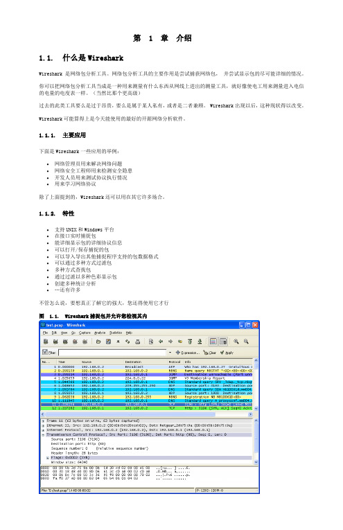
第 1 章介绍1.1. 什么是WiresharkWireshark 是网络包分析工具。
网络包分析工具的主要作用是尝试捕获网络包,并尝试显示包的尽可能详细的情况。
你可以把网络包分析工具当成是一种用来测量有什么东西从网线上进出的测量工具,就好像使电工用来测量进入电信的电量的电度表一样。
(当然比那个更高级)过去的此类工具要么是过于昂贵,要么是属于某人私有,或者是二者兼顾。
Wireshark出现以后,这种现状得以改变。
Wireshark可能算得上是今天能使用的最好的开源网络分析软件。
1.1.1. 主要应用下面是Wireshark一些应用的举例:∙网络管理员用来解决网络问题∙网络安全工程师用来检测安全隐患∙开发人员用来测试协议执行情况∙用来学习网络协议除了上面提到的,Wireshark还可以用在其它许多场合。
1.1.2. 特性∙支持UNIX和Windows平台∙在接口实时捕捉包∙能详细显示包的详细协议信息∙可以打开/保存捕捉的包∙可以导入导出其他捕捉程序支持的包数据格式∙可以通过多种方式过滤包∙多种方式查找包∙通过过滤以多种色彩显示包∙创建多种统计分析∙…还有许多不管怎么说,要想真正了解它的强大,您还得使用它才行图 1.1. Wireshark捕捉包并允许您检视其内1.1.3. 捕捉多种网络接口Wireshark 可以捕捉多种网络接口类型的包,哪怕是无线局域网接口。
想了解支持的所有网络接口类型,可以在我们的网站上找到/CaptureSetup/NetworkMedia.1.1.4. 支持多种其它程序捕捉的文件Wireshark可以打开多种网络分析软件捕捉的包,详见???1.1.5. 支持多格式输出Wieshark可以将捕捉文件输出为多种其他捕捉软件支持的格式,详见???1.1.6. 对多种协议解码提供支持可以支持许多协议的解码(在Wireshark中可能被称为解剖)???1.1.7. 开源软件Wireshark是开源软件项目,用GPL协议发行。
Windows 10 Step-by-Step Upgrade User Guide

Windows 10 Step-by-Step Upgrade User GuideFujitsu is committed to help you upgrade your PC to Windows 10. This user guide will provide you with useful information on how to install Windows 10 on your Fujitsu PCs.BEFORE UPGRADINGUpgrade PathsWindows 10 provides upgrade paths from Windows 7 SP1 and Windows 8.1 Update (KB2919355) or newer updates. Windows 7 (original release), Windows 8, and Windows 8.1 (original release) must first be updated to Windows 7 SP1 or Window 8.1 Update to be able to upgrade to Windows 10.AvailabilityWindows 10 is available from the Windows 10 download page.Non-Supported Upgrade OptionsCross-language installations are not supported if you plan to keep any apps or Windows settings.Cross-architecture upgrade from 32-bit to 64-bit OS is not supported. You will need to do a clean wipe and install.Data and Operating System BackupIt is always recommended to backup your personal files before you start the Windows 10 upgrade / clean installation.We would advise you to create copies of the recovery DVDs (Recovery Boot Disc, Factory Image Discs & Application Disc) using the Fujitsu MyRecovery or System Restore and Recovery applications.Please ensure that you perform this important step as Fujitsu is not liable for any data loss.Drivers and Utilities DownloadsDrivers for Windows 10 are installed by Windows Update.To ensure a smooth installation procedure, we would recommend you to visit Fujitsu Support Page for the Windows 10 drivers, utilities, firmware, applications and documentations.Please download and save them to external media, such as a portable hard disk drive (HDD), to prepare for your Windows 10 upgrade / clean installation.List of Systems Tested for UpgradeFujitsu has tested the following systems for upgrade to Windows 10. Please follow the step-by-step installation procedure for upgrading these systems to Windows 10.SERIES MODEL NAMEA AH552, AH544, AH564, AH555CELSIUS H730E E752, E733, E743, E753, E544, E554, E734, E744, E754L LH522, LH532 (Non-NVIDIA Graphics)P P702, PH702Q Q572, Q702, Q584, Q704, Q335, Q555, Q665, Q775S S752, S762, S792, SH782, S904, S935T T732, T902, T734, T904, T725, T935U UH572, U772, UH554, UH574, U745Fujitsu Requirements and Limitations for Specific FeaturesThere are some limitations after upgrading to Windows 10. Please refer to the Fujitsu Support Page for details.The following applications and features will no longer be supported after the Windows 10 upgrade:♦Auto Rotation Utility♦Bay Projector Software♦Bluetooth High Speed Technology♦ExpressCache♦Finger Zoom♦Fujitsu Display Manager♦Fujitsu Hotkey Utility♦Intel® Experience Center♦Intel® PROSet/Wireless WiFi Software tools♦Intel® Rapid Start Technology♦Intel® Smart Connect Technology♦Intel® WiDi♦McAfee Internet Security♦Norton Internet Security♦Quick Start Setting / Power Button Setting♦OmniPassWindows 10 Requirements and NotesThe upgradeability of a device has factors beyond the system specification. This includes driver and firmware support, application compatibility, and feature support, regardless of whether or not the device meets the minimum system specification for Windows 10.Applications, personal files and Windows settings will migrate as part of the upgrade; however some applications or settings may not migrate.Some features of Windows 7, Windows 8, and Windows 8.1 have been deprecated, and there are additional requirements to use certain Windows 10 features. For details, please visit:https:///en-us/windows/windows-10-specificationsPRE-UPGRADE STEPSPlease follow the below steps before upgrading to Windows 10:1)Login as AdministratorSign into your computer using an account with system administrator permissions2)Connect to the InternetConnect your computer to the internet before commencing on the upgrade.3)Connect Your Computer to an AC PowerIt is important to connect an AC adapter to your system during upgrade.4)Ensure Your Windows PC has the Latest Windows UpdatesWe would recommend you to apply all important Windows updates via "Windows Update"before proceeding with the Windows 10 upgrade.5)Backup Hard Disk DataWe would recommend you to perform a full backup of your files in case the upgrade procedure fails. Please backup all your important data and save them in a safe location before the upgrade.The following are a few suggestions on how to backup your critical data safely:♦Copy the important data to a network folder♦Burn the data to a CD or DVD♦Backup to an external storage (such as a hard drive or USB thumb drive)** NOTE: Fujitsu is not liable for any data loss during the upgrade process.6)Burn Windows Recovery MediaWe would recommend you to create System Recovery DVDs before performing any upgrade actions.Please ensure that you have a copy of the Recovery Boot Disc, Factory Image Discs & Application Disc. You may use the recovery media set in case you wish to revert the systems back toWindows 8/8.1 or Windows 7.However, all user data will be lost after the reverse process.7)Clear Security PasswordsWe would recommend you to clear the security feature passwords before the upgrade, asfollows:♦BIOS Setup Passwords (Master / User)♦BIOS Hard Disk Passwords (Master / User)♦Security Panel Passwords (Supervisor / User)** NOTE: If necessary, please backup your OmniPass profile. Fujitsu is not liable for any data loss during the upgrade process.8)Download Windows 10 Drivers, Utilities, Firmware, Applications and DocumentationsPlease visit the Fujitsu Support Page for the latest Windows 10 drivers, utilities, firmware,applications and documentations.9)Software Utility and Driver Un-installation/Update ProcedureReferring to your hardware configuration, please uninstall/update the following applications, drivers, and utilities to the Windows 10 compatible versions before or after upgrading toWindows 10:SOFTWARE NAME ACTION BEFORE UPGRADE ACTION AFTER UPGRADE Auto Rotation Utility Uninstall Use OS Auto Rotation Bay Projector Software Uninstall Not Supported Bluetooth High Speed Technology - Not Supported ExpressCache Uninstall Not Supported Finger Zoom Uninstall Not Supported Fujitsu Battery Utility Uninstall and Update -Fujitsu BIOS Driver - UpdateFujitsu Display Manager Uninstall Not Supported Fujitsu Disc Burning Utility - Uninstall and Update Fujitsu FUJ02B1 Device Driver - UpdateFujitsu FUJ02E3 Device Driver - UpdateFujitsu Function Manager Uninstall and Update -Fujitsu Hotkey Utility Uninstall Not Supported Fujitsu Pointing Device Utility (Win 7) - UpdateFujitsu Pointing Device Utility (Win 8.1) Update -Fujitsu Power Saving Utility (Win 7) Uninstall Install Function Manager Fujitsu Power Saving Utility (Win 8.1) - Update Function Manager Fujitsu Shock Sensor Utility - UpdateFujitsu System Extension Utility - UpdateFujitsu System Manager Uninstall UpdateIntel® Atom™ Processor Z3700 SeriesDriversUpdate -Intel® Experience Center Uninstall Not SupportedTable continued on next page...SOFTWARE NAME ACTION BEFORE UPGRADE ACTION AFTER UPGRADEIntel® PROSet/Wireless WiFi- Not Supported Software toolsIntel® Rapid Start Technology Uninstall Not Supported Intel® Rapid Storage Technology Update -Intel® Smart Connect Technology Uninstall Not Supported Intel® WiDi Uninstall Use OS Miracast LIFEBOOK Application Panel Update -McAfee Internet Security Uninstall Not Supported Norton Internet Security Uninstall Not Supported OmniPass Uninstall Not Supported PalmSecure Sensor Driver - UpdateQuick Start Setting /Uninstall Not Supported Power Button SettingRealtek Camera Driver - UpdateUp Time Monitor Update -Wireless Radio Switch Driver Update -UPGRADE STEPS1)Run the Upgrade ToolThe tool is available from the Windows 10 download page.2)Select [Upgrade this PC now]3)Select Language and PreferencesClick [Next] to continue.4)Accept the End-User Licensing Agreement (EULA)Click [Accept] to accept the EULA and continue with the upgrade.Clicking [Decline] will exit the upgrade.5)Start the UpgradeOnce download is completed, it will run through pre-install checks. If any warning message appears, please follow the instructions on the screen to resolve the issue.After passing the pre-install checks, click [Start the upgrade now] to upgrade immediately.6)Upgrade InstallationSystem restarts and the upgrade installs.7)Completing InstallationOnce the installation is completed:a)Restart occurs and system starts first boot experience.b)Sign-in screen displays, depending on the type of account.c)Click [Use express settings] to continue, or click [Customize settings] to personalize settings.d)Click [Next] to use the Windows 10 default apps, or click [Let me choose my default apps] tochange defaults.e)Logon to Windows.8)Continuing SetupIf you entered the password incorrectly previously, a screen will be shown prior to the color screen below prompting you to re-enter it.9)Process Completed♦For Local Accounts (with no password), Microsoft Account, Domain and Azure Active Directory (AAD) accounts, the logon screen will be displayed.♦For Local Accounts that had already provided passwords, you will see the Desktop.CLEAN INSTALL STEPS1)Create Installation MediaYou can create your own installation media using either a USB flash drive or a DVD. However, DVD installation is highly recommended. To get the installation media, please visit the Windows10 download page for more information.2)Boot up the System with the Windows 10 Installation Disc3)Select Language and PreferencesClick [Next] to continue.4)Click [Install now]5)Enter the Product KeyType the product key into the text box, and then click [Next].** NOTE: Skip this step if you have successfully upgraded to Windows 10 with the upgrade offer previously.6)Read and Accept the Microsoft Software License TermsClick [I accept the license terms] (required to use Windows), then click [Next].7)Select Custom InstallClick [Custom: Install Windows only (advanced)] to proceed with clean install.Note: All user data will be deleted. Please ensure that you have the corresponding backups.8)Delete All PartitionsSelect each partition and click [Delete] to remove all partitions on your hard disk. Then select the freed up unallocated space and click [Next] to continue.9)Installing WindowsWindows 10 clean installation begins.10)Get ConnectedIf you use a wireless network, connect to your access point.11)Configure Windows SettingsClick [Use express settings] to automatically configure your Windows 10 settings.Note: This step is optional. If you prefer your own settings, click [Customize settings] instead.12)Select the Owner of the PCSelect [My organization] or [I own it], and follow the instructions.13)Setup AccountIf you have a Microsoft account, enter your account name and password, then click [Sign in].If you want to use a new Microsoft account, click [Create one!].Otherwise, click [Skip this step] to create a Local account.14)Setup a PINIf you wish to use a PIN, click [PIN me!] and follow the instructions.Please click [Skip this step] if it is unnecessary.15)OneDrive Opt-inClick [Next] to opt-in to OneDrive. Otherwise click [Save new files only to this PC by default].16)Cortana Opt-inClick [Next] to opt-in to Cortana. Otherwise click [Not now].17)Installing Apps18)Setup CompletedPlease wait a while before Windows starts up.POST-UPGRADE STEPSAfter upgrading your PC to Windows 10, Fujitsu recommends that you install a few updates.Please proceed to install all the drivers, utilities and applications.a)Installation of the latest Windows Updates from Microsoftb)Installation of the drivers and utilities downloaded** NOTE: For the updated Fujitsu MyRecovery, also known as Fujitsu Restore and Recovery, the Recovery Disc burning feature will be limited to ONE time only. Please handle your Recovery Discs with care and keep it safe.c)You may refer to the Fujitsu Support Page for any update patches. Whenever available,please download and apply the update patch.After completing the installation of all drivers, utilities and applications, you may visit Microsoft Windows 10 pages to learn more.Fujitsu and the Fujitsu logo are registered trademarks of Fujitsu, Ltd. Windows is a registered trademark of Microsoft Corporation.All other trademarks mentioned herein are the property of their respective owners. We cannot guarantee the accuracy of the contents of this document. We disclaim liability for errors, omissions or future change.© 2015 Fujitsu PC Asia Pacific, Ltd. All rights reserved.。
UserGuide

6. 插入网线
7. 在PC端开启tftp服务器, 并且将MLO, u-boot.img, uImage, ubi.img拷贝到tftp根目录下
8. 在u-boot中运行以下命令:
-----
MLO:|
-----
nandecc hw 2
mw.b 0x82000000 0xff 0x20000 # 用0xff填充从0x82000000开始的0x20000个字节, 内存的物理启始地址为0x80000000
dhcp 0x82000000 192.168.16.188:MLO # 将192.168.1.102这个tftp服务器上的MLO文件下载到0x82000000其实的内存空间
nand write 0x82000000 0x280000 0x500000
mw.b 0x82000000 0xff 0x2800000
dhcp 0x82000000 192.168.16.188:ubi.img
nand write 0x82000000 0x780000 0x2800000
mw.b 0x82000000 0xff 0x2800000
nand erase 0x2f80000 0x2800000
dhcp 0x82000000 192.168.16.188:ubi.img
nand write 0x82000000 0x2f80000 0x2800000
-----
nand write 0x82000000 0x00000 0x20000
EVE USER'S GUIDE

Table of Contents
Getting Started: Registration ......................................................................................................................... 6
Personal Zone: Groups .......................................................................................... 11
prti1516_users_guide用户手册

Pitch pRTI™User’s GuidepRTI™ 1516 USER’S GUIDEContents1INTRODUCTION 41.1ABOUT THIS DOCUMENT 4 1.2ABOUT PITCH TECHNOLOGIES 5 1.3ABOUT IEEE 1516 HLA 5 1.4ABOUT THE RUN TIME INFRASTRUCTURE 6 1.5ABOUT PRTI™ 1516 6 1.6PRODUCT LICENSING STRUCTURE 72PREPARING FOR PRTI™ 1516 82.1 A TOPOLOGY AND COMPONENTS EXAMPLE 8 2.2THE CENTRAL RTI COMPONENT (CRC) 9 2.3THE FEDERATES 9 2.4THE LOCAL RTI COMPONENT (LRC) 9 2.5THE FOM FILE 9 2.6THE COMPUTERS 10 2.7NETWORKING 103INSTALLING PRTI™ 1516 123.1WINDOWS INSTALLATION 12 3.2VERIFYING THE WINDOWS INSTALLATION 16 3.3LINUX INSTALLATION 18 3.4VERIFYING THE LINUX INSTALLATION 18 3.5INSTALLING ON SOLARIS 20 3.6VERIFYING THE SOLARIS INSTALLATION 20 3.7INSTALLING ON OTHER PLATFORMS 21 3.8INSTALLING PRTI™ 1516 FOR EXTREME PERFORMANCE 224UNINSTALLING PRTI™ 1516 234.1UNINSTALLING ON WINDOWS 23 4.2UNINSTALLING ON LINUX 23 4.3UNINSTALLING ON SOLARIS 23 4.4UNINSTALLING ON OTHER PLATFORMS 235RUNNING PRTI™ 1516 245.1USING THE GRAPHICAL USER INTERFACE 24 5.2USING THE COMMAND LINE INTERFACE 346RUNNING PRTI™ 1516 IN SERVICE-MODE 366.1INTRODUCTION 36 6.2LIMITATIONS 36 6.3INSTALLING THE SERVICE 36 6.4UNINSTALLING THE SERVICE 38 6.5SERVICE MANAGEMENT 387USING THE PRTI™ 1516 WEB GUI 417.1INTRODUCTION 41 7.2ACCESSING THE WEB GUI 42 7.3OPERATING THROUGH FIREWALLS 438DEVELOPING WITH PRTI™ 1516 448.1MICROSOFT VISUAL STUDIO 6.0 ON WINDOWS 44 8.2MICROSOFT VISUAL STUDIO .NET ON WINDOWS 48 8.3GCC ON LINUX 53 8.4JAVA 54 9WRITING A SIMPLE FEDERATE IN C++ 55 9.1THE FEDERATEAMBASSADOR AND THE RTIAMBASSADOR 559.2THE FEDERATION OBJECT MODEL 56 9.3PUBLISHING AND SUBSCRIBING TO INFORMATION 57 9.4SENDING INTERACTIONS 57 9.5RECEIVING INTERACTIONS 57 9.6CONCLUSIONS 5810WRITING A SIMPLE FEDERATE IN JAVA 5910.1THE FEDERATEAMBASSADOR AND THE RTIAMBASSADOR 59 10.2THE FEDERATION OBJECT MODEL 60 10.3PUBLISHING AND SUBSCRIBING TO INFORMATION 61 10.4SENDING INTERACTIONS 61 10.5RECEIVING INTERACTIONS 61 10.6CONCLUSIONS 6211TICK AND PROCESS MODELS 6311.1MULTIPLE TICK VERSIONS 63 11.2PRACTICAL GUIDELINES 63 11.3EXPLANATION OF PROCESS MODELS 6412DEBUGGING AND TRACING 6512.1OVERVIEW 65 12.2ENABLING THE TRACING 65 12.3FORMAT OF THE TRACE LOG 66 12.4 A SAMPLE TRACE LOG 6613NETWORKING 6813.1WHEN TO RECONFIGURE NETWORKING 68 13.2OVERVIEW OF PRTI™ 1516 COMMUNICATION 69 13.3USING MULTICAST 70 13.4OPERATING OVER FIREWALLS 70 13.5NETWORK SETTINGS 70 13.6PRTI™ 1516 AND PITCH BOOSTER™ 71 14ADVANCED PRTI™ NETWORK PERFORMANCE TUNING 74 14.1INTRODUCTION 74 14.2FEDERATE TUNING 74 14.3SETTING TUNING PARAMETERS 75 14.4PRTI™ 1516 TUNING ALGORITHMS 77 15CONFIGURATION REFERENCE 80 15.1SETTINGS FOR THE CENTRAL RTI COMPONENT 80 15.2SETTINGS FOR THE LOCAL RTI COMPONENT 81 15.3LRC SETTINGS FOR C++ FEDERATES 87 15.4TIME CLASS SETTINGS 87 16COMMON ERRORS 88 16.1COMPILING C++ FEDERATES 88 16.2COMPILING JAVA FEDERATES 89 16.3STARTING PRTI™ 1516 89 16.4RUNNING C++ FEDERATES 90 16.5FEDERATION STARTUP 91 16.6GET HANDLES AND REGISTER OBJECT INSTANCES 92 16.7UPDATES AND INTERACTIONS 93 16.8TIME MANAGEMENT 94 16.9MISCELLANEOUS 951Introduction1.1 About This DocumentpRTI™ and Visual OMT™ are registered trademarks belonging to PitchTechnologies AB. All rights reserved.This document provides information about how to install, run, troubleshoot andoptimize pRTI™ 1516, the leading commercial RTI for the HLA. The acronymRTI stands for Run-Time Infrastructure, pRTI™ stands for portable RTI and HLAstands for High Level Architecture, which is a standard for simulationinteroperability.These are the main audiences for this document:Developers of HLA compliant simulation system who wish to use pRTI™ 1516 in their development projects.IT Staff responsible for setting up and maintaining HLA based simulation applications in their IT environment. This group can concentrate on chapters2, 3 and 5.Technical specialist who wish to evaluate pRTI™ 1516 as aninteroperability infrastructure for their projects or products.The outline of the document is as follows:This introduction gives an initial overview of HLA and pRTI™ 1516.Preparing for pRTI™ 1516 describes the set-up you need to run anddevelop for pRTI™ 1516, such as networking, hardware, software andparticipating systems.Installing pRTI™ 1516 describes how to install pRTI™ 1516 on various platforms such as Windows, Linux etc.Running pRTI™ 1516 describes how to run and monitor your simulations using a graphical and command line interface.Running pRTI™ 1516 In Service-Mode describes how to install and setup pRTI™ 1516 to run as a service on Windows and Linux.Using the pRTI™ 1516 Web GUI describes how to access the pRTI™ 1516 web GUI.Developing with pRTI™ 1516 shows how to set up your developmentenvironment to be able to build federates.Writing a simple federate in C++ contains an example federate complete with C++ source code including instructions on how to compile and run thefederate.Writing a Simple Federate in Java contains an example federate complete with Java source code including instructions on how to compile and run thefederate.Tick and Process Model describes how the RTI and the federate share the CPU and how to achieve optimal performance and responsiveness.Debugging and Tracing describes the abilities of pRTI™ 1516 to aid you in debugging your federation.Networking describes networking functionality and tuning for pRTI™ 1516.Advanced pRTI™ Network Performance Tuning describes the advanced network tuning functionality available in pRTI™ 1516.Configuration Reference contains a summary of all the configuration switches that can be used with pRTI™ 1516.Common errors lists common errors and how to resolve them.1.2 About Pitch TechnologiesPitch Technologies is the world leading supplier of interoperability enablingproducts for simulation and training. Based on open international standards Pitchprovides COTS products for developing and deploying distributed simulationsaccording to the High Level Architecture (HLA). Our products pRTI™, 1516Adapter™, DIS Adapter™ and Visual OMT™ are used in a variety of both civilian and defense simulations world-wide to support training, acquisition and analysis.Furthermore, many of the simulation industry’s vendors use the Pitch products toHLA enable their solutions.1.3 About IEEE 1516 HLAThe HLA standard was initially defined in 1995 based on experiences from earlier simulation interoperability standards. The idea was to create a standard that couldembrace many domains and types of simulation. Although earlier standards existed they were limited to specific simulation domains or did not provide services formanaging time in simulations.The HLA standard has been developed in several steps from 1.0 up to the well-known HLA 1.3 standard. After this step it was decided to broaden the usageoutside the US defense, so the latest version of the standard is established as anopen and international IEEE standard: the IEEE 1516 HLA standard. The IEEE1516 HLA standard is the intended goal also for the US Department of Defensesimulations.IEEE accepted the standard in 2000. Since then the development of tools and RTI:s has started. The first complete RTI implementation, pRTI™ 1516, has beenavailable since December 2001. Other HLA 1516 tools available include objectmodel tools such as Visual OMT™ 1516. During 2003 more tools from severalvendors have been introduced.Starting with version 2.1, pRTI™ 1516 is based on the IEEE standards and theDMSO interpretations version 2.The IEEE 1516 standard is in active use in Europe, Asia and the US. Worth noting is the acceptance by the non-defense community. Commercial applications basedon the IEEE 1516 standard have already been completed and delivered to the enduser.HLA lets you interconnect simulations, devices and humans in a commonfederation. HLA builds on composability, letting you construct simulations frompre-built components.Each computer based simulation system is called a federate and the group ofinteroperating systems is called a federation.The HLA standard consists of three parts:The HLA rules that the entire federation and federates have to follow.The Object Model Template, which is used to describe object models for federates and federations. The leading graphical tool for working which suchobject models is Visual OMT™ 1516 from Pitch AB.The HLA Interface Specification, which describes the functionality that the RTI has to provide. The US Defense Modeling and Simulations Office(DMSO) verify RTI products to guarantee that they adhere to thisspecification. pRTI™ 1516 is certified by DMSO. The certification processwas completed in March 2003.To be able to successfully develop HLA compliant applications it is necessary togain a deeper understanding of HLA than this document provides. Recommendedsources are the DMSO web site (), HLA courses (availablefrom Pitch, see http://www.pitch.se for more information) and books. You may also want to study the FEDEP, which is the recommended process for developingfederations.The book Creating Computer Simulation Systems: An Introduction to the HighLevel Architecture by Dr. Frederick Kuhl, Dr. Richard Weatherley and Dr. JudithDahmann (ISBN 0-13-022511-8) contains an introduction and an in-depthwalkthrough of the old 1.3 version of the HLA standard.1.4 About the Run Time InfrastructureThe Run Time Infrastructure is responsible for the information exchange during the execution. It will let federates join and resign, declare their intent to publishinformation, send information about objects, attributes and interactions,synchronize time, etc. Note that the HLA is not the RTI but it specifies that theremust be an RTI with a standardized interface. The interface is specified in the HLA standard, but the implementation of the interface specification is left to the RTIdeveloper.1.5 About pRTI™ 1516The product pRTI™ 1516 is an implementation of the IEEE 1516 InterfaceSpecification. It lets you integrate simulations in an HLA compliant way. You can mix different operating systems and programming languages. The main advantages of pRTI™ 1516 are:It is complete, certified and HLA compliant. pRTI™ 1516 is a complete implementation of the HLA specification that has been certified by DMSO.This is a requirement for your federation to be HLA compliant.It offers excellent performance. pRTI™ 1516 features sender-side filtering for updates and interactions, which will substantially reduce network andCPU load in large federations. You may also reduce the workload of yourfederates using advisories which impose very little overhead. Still pRTI™1516 has very modest CPU and memory requirements.It provided advanced debugging capabilities. There is an extensive GUI that allows you to inspect the state of your federation during runtime as wellas a powerful set of debugging tools.It is easy to install and run. pRTI™ 1516 is extremely easy to install and configure. It is easy to mix various platforms and languages in the samefederation. The network setup is very simple and it works well over a WANsuch as the Internet.It is network-friendly. You can do optimizations and configurations for LAN, WAN and firewalls and inspect the status of the network graphically.It is commercially packaged and supported. It is possible to get an OEM license to include it with your products. You can get local support andconsulting in several countries (including the USA) from Pitch or one of ourdistributors. See http://www.pitch.se for details.It is superior for long-running federations. It handles unreliable federates gracefully including automatic resign, ownership and time managementrecovery and more.It gives you the ability to integrate your existing C/C++ simulators with platform-independent Java systems. pRTI™ 1516 provides API:s for bothC++ and Java, so you can use federates written in any of those languagestogether in the same federation.pRTI™ 1516 is developed by Pitch. Professional consulting services and training is also available.1.6 Product Licensing StructureThe product is structured in the following way:The pRTI™ 1516 base license enables you to run pRTI™ 1516 with the Java APIwith a certain number of federates. You may for example purchase a license for 10 federates. This will enable you to connect up to 10 federates (simulation systems)together. The federates may run on the same computer or several differentcomputers. The GUI for pRTI™ 1516 is included in the base license.In addition to this you can purchase add-ons such as:C++ interface for Windows.C++ interface for Linux.C++ interface for Solaris, etc.2 Preparing for pRTI™ 1516This chapter describes the computer hardware and software that is needed to run a simulation using pRTI™ 1516. It also describes various configurations that are possible.2.1 A Topology and Components ExampleAn example of a federation of computer-based simulations that interoperates using pRTI™ 1516 is described in the Figure 1Computer A Computer B Computer CFigure 1 – An example topology.The environment in Figure 1 consists of:1. The Central RTI Component that manages the federation.2. The federates participating in the federation.3.The Local RTI Component which each federate use to communicate in thefederation.4. The FOM file that describes the Federation Object Model.The federates and the Central RTI Component are running on separate computers. Note that this is not required. Any number of federates can run on the same computer, and any number of federates can run on the same computer as the Central RTI Component. Another possible topology that shown in Figure 2.Computer A Computer BFigure 2 - Another example topology.2.2 The Central RTI Component (CRC)The CRC is the central component of pRTI™ 1516, also known as the RTIexec. It provides a graphical and a command line interface that lets you monitor theexecution. It is responsible for coordinating the entire federation and distributes the work between the Local RTI Components.When a federate wants to join a federation execution, it connects to the CRC andreceives information about the federation execution such as which other federatesare currently joined to the federation and how to communicate with them.2.3 The FederatesThe federates may be implemented in several languages:C++Any computer language with an interface module written in C++JavaAny computer language, wrapped in JavaYou may mix different implementation languages in the same federation. Note that you need to purchase the C++ add-on (as mentioned in section 1.6) to be able tocall pRTI™ 1516 directly from a C++ application.2.4 The Local RTI Component (LRC)This is a local component that takes care of the local federate’s need to exchangeinformation with other federates. Every federate is compiled and linked with acomponent that contains the classes and methods that are used to connect to thefederation. This component is called the Local RTI Component.This makes pRTI™ 1516 a distributed application, consisting of both the CRC anda number of LRC:s (one for each federate). Figure 3 illustrates the relationshipbetween the CRC, the LRC and the federates.Figure 3 – The relationship between the CRC, the LRC and the federates.2.5 The FOM FileThis is a file that contains the Federation Object Model. The Federation ObjectModel describes the information exchange in the federation. This includes objects, interactions, attributes, parameters and data types for all the information that isexchanged between the federates. The data in the file is XML formatted.Federation object models can be edited using Visual OMT™ 1516. You can use itto create, edit and manage Federation Object Models. Figure 4 shows a screenshot of the tool.Figure 4 – Visual OMT™ 1516 object modeling tool.2.6 The ComputersThe computers that you use will have to provide appropriate networking according to the next section as well as meet the requirements of the local federates.Supported operating systems include:Windows NT/2000/XP on Intel x86.LinuxSolarisYou may mix different brands and operating system in the same federation.Additional platforms may be available and customer ports can be performed.Contact Pitch or your local dealer for more information.2.7 NetworkingThe protocol used for pRTI™ 1516 is the industry standard TCP/IP. The mostcommonly used network configurations for simulations are:An Ethernet-based LAN (Local Area Network). All computers are equipped with Ethernet cards and connected to a hub or switch with 10/100/1000 Base-T cables. Note that using a switch may significantly improve performance for federations exchanging large amounts of data.WLAN. All computers are equipped with a WLAN card and establishes wireless connections through a WLAN hub or switch.Dial-up connections to the network (or the Internet) using a modem.All federates run on a single computer, which is not connected to a network.In this case you will usually need a piece of software called a loop-backdevice. This device is usually installed by default in some operating systems (such as Linux), but may need to be added for others (such as Windows2000).In addition to this you will need to be able to specify the address of the RTI to which you are trying to connect using one of the following:If you have a DNS service it will provide the translation between names (such as myhost.pitch.se) and IP addresses (such as 192.168.1.1). In this case you will need to know the name of the computer running pRTI™ 1516. Note that the DNS server should also be able to resolve IP addresses to names, also known as reverse lookups.If you do not have a DNS service you can use the IP address directly.If you are using a loop-back device, the standard address is 127.0.0.1. Contact your network administrator for details about your organization’s network. The default pRTI™ 1516 settings are suitable for both local area networks and wide area networks. pRTI™ 1516 runs well over WAN:s with routers, for example over the Internet or big corporate networks. See chapter 13 for more information.3Installing pRTI™ 1516This chapter covers how to install and verify the Central RTI Component ofpRTI™ 1516 using the sample federates. It also covers the installation of the LocalRTI Components for the use by your own federates.3.1 Windows InstallationBefore you start, check that you have:The installation executable.You license number that you will use to activate the software. This is not required for the pRTI™ 1516 LE version.Perform the initial installation by double-clicking on the installer. A graphicalinstaller will now start. The first screen you will see contains an important note tousers upgrading from an older version of pRTI™ 1516. As of version 2.3 a newinternal licensing structure is used and old license keys will no longer be valid. Ifyou have received the new pRTI™ 1516 version as part of a maintenance contract,please contact your supplier to obtain a new license key.Figure 5 shows the introduction screen which gives you a general introduction tothe installation and informs you of the new licensing structure.Figure 5 – Installation introduction.Click Next to continue. The license agreement will then be presented to you asshown in Figure 6.Figure 6 – End user license agreement.Read the license agreement and make the appropriate selection. Then click Next. You can now select which type of installation you want. The default selection installs all components, including documentation and example federates. If you are installing on a computer that will run the actual RTI (the CRC) we recommend the Complete installation option. If you are installing on a computer where only federates will be running, we recommend the LRC Only option.Figure 7 – Install set selection.Make your selection and click Next.You will then be asked where to install pRTI™ 1516. You are recommended not to change the default directory.Figure 8 – Installation destination.Make your selection and click Next. You are then asked in which program group that you want the shortcuts.Figure 9 – Create icons in the start menu.Click Next after making your selection. Finally a summary will be presented to you before the installation starts as shown in Figure 9.Figure 10 – Installation summary.Press Install to finish the installation.Figure 11 – Installation progress.When the installation is complete you will see the screen shown in Figure 12.Figure 12 – Installation complete.Press Done to close the installer.3.2 Verifying the Windows InstallationIt is now time to verify your installation.Start pRTI™ 1516 using the start menu command:Start → Programs → pRTI 1516 → pRTI 1516This starts both a textual and a graphical user interface. If you are using the fullversion of pRTI™ 1516 (not LE) you will be required to enter the license number.You may find it more convenient to use cut-and-paste to do this.Figure 13 – Enter the license number.Important note: The license number is used to activate the Central RTIComponent. You are only allowed to use the license number on one computer. Youshould (and need) not enter the license number on computers that only run federates that use the Local RTI Component.Figure 14 – The pRTI™ 1516 GUI.Start a Java based federate using the start menu command:Start → Programs → pRTI 1516 → Samples → Chat Federate (Java)Start a C++ based federate using the start menu command:Start → Programs → pRTI 1516 → Samples → Chat Federate (Visual C++)You will be prompted to enter a name, as an example we will use Fred and Barney.Enter your name: FredAfter entering the names, type a message in one of the federate windows and press the Enter key.> Hello BarneyThe message will now appear in the other federate window (Barney’s) as: > Fred: Hello BarneyNow click in the other federate window (Barney’s) and type the following and finish by pressing the Enter key.> Hello FredThe message will now appear in the other federate window (Fred’s) as: > Barney: Hello FredNow type a period (.) in each federate window followed by the Enter key twice to shut down the chat federates.Switch to the pRTI™ 1516 textual interface and type QUIT followed by the Enter key or click Shut Down RTIexec in the graphical interface. Both these alternatives will shut down the CRC.If you want to run the chat sample over a network, edit the run.bat file in thesamples/chat subdirectory. Add a space followed by the IP address of the computer running the Central RTI Component last on the line that ends with Chat. Start that federate and watch it connect to the remote CRC of the pRTI™ 1516.3.3 Linux InstallationBefore you start, check that you haveThe installation executable.You license number that you will use to activate the software. This is not required for the pRTI™ 1516 LE version.Execute the file prti1516_vX.Y.Z.bin (where X.Y.Z is the pRTI™ 1516 version).Note that you may have to modify the file permissions using the chmod command before running the file:[root@Enorm root] # ./chmod u+x prti1516_v3.0.0.bin[root@Enorm root] # ./prti1516_v3.0.0.binA graphical installer will now start. The graphical installer is very similar to theWindows installer, so check the instructions in section 3.1 if anything is unclear.3.4 Verifying the Linux InstallationIn the bin directory, found in the installation directory, there are three shell scripts, prti1516.sh, java-chat.sh and cpp-chat.sh. These can be used to start pRTI™ 1516 and the two Chat federates that are supplied with the default installation. There isalso a fourth shell script, lrcGui1516.sh, that is used to modify the LRC settings.See section 15.2 for more information. To start pRTI™ 1516, run the fileprti1516.sh. This starts both a textual and a graphical user interface. If you areusing the full version of pRTI™ 1516 (not LE) you will be required to enter thelicense number as shown below. You may find it convenient to use cut-and-pastewhen doing this.[root@Enorm root]# cd /opt/prti1516/bin/[root@Enorm bin]# ./prti1516.shRTIexec for pRTI(tm) 1516 v3.0.0 Certified for IEEE 1516Copyright (c) 2000-2005 Pitch Technologies AB, http://www.pitch.seJava Home = /opt/prti1516/jreCLASSPATH = .Java Ext Dirs = /opt/prti1516/jre/lib/extpRTI Classes = file:/opt/prti1516/jre/lib/ext/prti1516.jar!User Name = rootUser Home = /rootSettings dir = /root/prti13License file: /root/prti1516/pRTI1516.licensePlease enter license number:>After entering your license number the CRC GUI will start as shown in Figure 15.Figure 15 – The pRTI™ 1516 GUI.Important note: The license number is used to activate the Central RTI Component. You are only allowed to use the license number on one computer. You should (and need) not enter the license number on computers that only run federates that use the Local RTI Component.To start the Java Chat federate, run the java-chat.sh file in a new command prompt window. Make sure that pRTI™ 1516 is running before you start the federate.[root@Enorm root]# cd /opt/prti1516/bin/[root@Enorm bin]$ ./java-chat.shEnter your name: FredType messages you want to send. To exit, type . <ENTER>>Now, to start the C++ Chat federate, open another command prompt window and run the cpp-chat.sh file.[root@Enorm root]# cd /opt/prti1516/bin/[root@Enorm bin]# ./cpp-chat.shEnter your name: BarneyType messages you want to send. To exit, type . <ENTER>>Enter a message in one of the federate windows (Barney’s):> Hello FredFinish by pressing the Return key. Watch the message appear in the window of the other federate:> Barney: Hello FredNow click in the other federate window (Fred’s) and type:> Hello BarneyFinish by pressing the Return key. Watch the message appear in the window of the other federate:> Fred: Hello BarneyNow type a period (.) in each federate window followed by the Return key twice.Switch to the pRTI™ 1516 textual interface and type QUIT followed by Return.3.5 Installing on SolarisBefore you start, check that you haveThe installation executable.You license number that you will use to activate the software. This is not required for the pRTI TM 1516 LE version.Execute the file prti1516_vX.Y.Z.bin (where X.Y.Z is the pRTI™ 1516 version).Note that you may have to modify the file permissions using the chmod commandbefore running the file:bash-2.05$ chmod u+x prti1516_ vX.Y.Z.binbash-2.05$ ./prti1516_ vX.Y.Z.binA graphical installer will now start. The graphical installer is very similar to theWindows installer, so check the instructions in section 3.1 if anything is unclear.After the graphical installer completes pRTI™ 1516 will be installed with the Java bindings only. If you also need the C++ bindings (and have the appropriate license) you will need to perform some additional steps.Depending on which C++ environment you use, you’ll need to install differentlibraries. In the pRTI™ 1516 installation directory you’ll find one or more fileswith the general name SunOs_<os version>_<compiler>_<compilerversion>.tar.zip, e.g. SunOS_5.9_CC_6.2.tar.zip. These files contain the C++binaries used by pRTI™ (including the sample Chat federate) for the environment specified by the file name. To install the appropriate C++ binding simply followthe procdure below:1.Open a console window and unzip the file. In this example we’re installingthe C++ bindings built on Solaris 9 using the Forte 6 Update 2 compiler.bash-2.05$ cd /opt/prti1516/bash-2.05$ unzip SunOS_5.9_CC_5.6.tar.zipArchive: SunOS_5.9_CC_5.6.tar.zipinflating: SunOS_5.9_CC_5.6.tar2.Unpack the resulting tar file.bash-2.05$ tar xvf SunOS_5.9_CC_5.6.tarx ./lib, 0 bytes, 0 tape blocksx ./lib/librti1516.so, 1189448 bytes, 2324 tape blocksx ./samples, 0 bytes, 0 tape blocksx ./samples/chatcc, 0 bytes, 0 tape blocksx ./samples/chatcc/ChatCC, 206884 bytes, 405 tape blocksbash-2.05$That’s it! Now just verify your installation as described below and you’ll be ready to start using pRTI™ 1516.3.6 Verifying the Solaris InstallationIn the bin directory, found in the installation directory, there are three shell scripts, prti1516.sh, java-chat.sh and cpp-chat.sh. These can be used to start pRTI TM 1516 and the two Chat federates that are supplied with the default installation. To startpRTI TM 1516, run the file prti1516.sh:bash-2.05$ cd /opt/prti1516/bin/bash-2.05$ ./prti1516.sh。
User Guide

User GuideTable of ContentsWrite:OutLoud To Go Toolbar. . . . . . . . . . . . . . . 3One-Click Access to Common Tasks. . . . . . . . . . . . . . . . . 3Text Navigation and Selection Buttons. . . . . . . . . . . . . . . 3Speech Buttons. . . . . . . . . . . . . . . . . . . . . . . . . . . . . . . . 4Tool Buttons. . . . . . . . . . . . . . . . . . . . . . . . . . . . . . . . . . 5Text Buttons. . . . . . . . . . . . . . . . . . . . . . . . . . . . . . . . . . 6Write:OutLoud To Go Menus. . . . . . . . . . . . . . . . 6File Menu. . . . . . . . . . . . . . . . . . . . . . . . . . . . . . . . . . . . 7Edit Menu. . . . . . . . . . . . . . . . . . . . . . . . . . . . . . . . . . . . 9Tools Menu. . . . . . . . . . . . . . . . . . . . . . . . . . . . . . . . . . 10Text Menu. . . . . . . . . . . . . . . . . . . . . . . . . . . . . . . . . . . 11Options Menu. . . . . . . . . . . . . . . . . . . . . . . . . . . . . . . 12Speech Menu. . . . . . . . . . . . . . . . . . . . . . . . . . . . . . . . 12Keyboard Shortcuts. . . . . . . . . . . . . . . . . . . . . . . 14Write:OutLoud®To Go TrademarksThe Don Johnston logo and Write:OutLoud are registered trademarks and TheLeader in Learning Intervention Resources is a trademark of Don JohnstonIncorporated.Dana is trademark and AlphaSmart is a registered trademark ofAlphaSmart, Inc.Macintosh is a registered trademark of Apple Computer, Inc.Windows is a registered trademark of Microsoft Corporation.Adobe and Reader are either registered trademarks or trademarks of AdobeSystems Incorporated in the United States and/or other countries.Graffiti is a registered trademark of Palm, Inc.All other product or corporate names are trademarks or registered trademarks oftheir respective companies and are used for explanation only and to the owner'sbenefit, without intent to infringe.Write:OutLoud To Go © Copyright 2004, Don Johnston Incorporated.All rights reserved.User Guide Write:OutLoud to Go © Copyright 2004Don Johnston Incorporated. All rights reserved.The Spelling portion of this product is based on Proximity Linguistic Technology.®THE PROXIMITY/FRANKLIN DATABASE © 1994, Franklin Electronic Publishers,Inc. All rights reserved, Proximity Technology Inc. Geographical Supplement© Copyright 1990/1994 Merriam-Webster® Inc./Franklin ElectronicPublishers, Inc. © Copyright 1994. All rights reserved, Proximity Technology Inc.THE PROXIMITY/FRANKLIN DATABASE © Copyright 1997, Franklin ElectronicPublishers, Inc. © Copyright 1998. All rights reserved, Proximity Technology Inc.Write:OutLoud To Go contains PrintBoy by Bachmann software.Published by:Don Johnston Incorporated26799 West Commerce DriveVolo, IL 60073800.999.4660 (USA/CANADA)847.740.0749Technical SupportSupport@800.889.5242 (USA/CANADA)Printed in the United States of America, September 2004Write:OutLoud To Go ToolbarWrite:OutLoud To Go is a talking word processor filled with features thatincrease its ease of use. Many functions can be carried out by simply clicking the toolbar at the top of the Write:OutLoud To Go screen, making importantword processing features immediately available without using pull-down menus.Writers click buttons to navigate through text, check spelling and more.One-Click Access to Common TasksWhen you activate Write:OutLoud To Go, you're ready to type and createdocuments immediately. For ease of use, the buttons on the toolbar are grouped according to tasks.Text Navigation and Selection ButtonsTools for text navigation and selection help writers quickly and efficientlymove through and review their writing.These self-explanatory tools are designed for ease of use by students. There are many more keyboard shortcuts for text navigation and selection listed in Keyboard Shortcuts at the end of this User Guide.BeginningTap Beginning to move your cursor to the beginning of the document.Use this to reread the work.MoveTap Move to move your cursor to the next sentence. Use this to quickly navigate through a document for reading and revising the work.3Write:OutLoud ®To Go© Don Johnston Incorporated USER GUIDENavigation Speech Tools Text AppearanceMoves cursor to the beginningMoves cursor tothe next sentence Selects the next sentence Moves cursor to the end of document Note:A sentence must end with a period,question mark or exclamationpoint in order for Write:OutLoud To Go to recognize it as a sentence.Write:OutLoud®To Go SelectTap Selectto highlight the next sentence. Use this to quickly select “chunks”of text for reading aloud or revising sentence-by-sentence.EndTap End to move directly to the end of the document. Use this to quickly getto the end of a document to add to existing work.Speech ButtonsSpeech feedback gives writers immediate auditory reinforcement of what they havejust typed, the opportunity to self-correct based on what they hear and motivatingauditory support during the revision process.SpeakTap Speak to hear the highlighted text or the sentence containing the cursor.Tap again to hear the next sentence spoken. Use this to read through thedocument sentence-by-sentence for more effective revision.Write:OutLoud To Go speaks highlighted text or, if no text is highlighted, speaksthe sentence containing the cursor.Select again and the next sentence is spoken. With this feature, you can movethrough your entire document sentence-by-sentence, speaking each sentence as you go.To speak specific words or sentences, highlight the text first, then tap Speak.To speak the entire document, choose Select All in the Edit menu and tap Speak.RepeatTap Repeat to hear again what was just spoken. Use this to repeat what wasjust heard to facilitate accurate proofreading and effective revision.StopTap Stop to stop the current speech. Use this to immediately interruptspeech during revision.© Don Johnston Incorporated USER GUIDE4Note:If your cursor is in the middle of a sentence,Select highlightswords from the cursor to the end of the sentence.Speak sentenceor selectionRepeatStop speakingNote:Sentences are spoken until sentence-ending punctuation or new paragraphsare encountered.5Write:OutLoud ®To GoWrite:OutLoud To Go includes many more speech options that you can turn on and off to meet writers' needs. SeeWrite:OutLoud To Go Menus,for more information.Tool Buttons Print One Tap Print One to print one copy of the current document. Use thisto bypass choosing any print settings.Check SpellingOften, struggling writers write very little text because of poor spelling or vocabulary. The Check Spelling Tool feature in Write:OutLoud To Go helps writers with editing for mechanics.Tap Check Spelling from anywhere in the document to begin the Franklin Spell Checker. Write:OutLoud To Go always checks the entire document for spelling errors.Write:OutLoud To Go displays the Spelling dialog when it finds a word that is not in either the regular Franklin or User dictionaries.The spell checker displays the sentence containing the unknown ormisspelled word (highlighted) along with suggested known orcorrect words.To hear the word in question spoken in context, tap the first .To hear suggested words, tap the second to speak the new word. To select the word suggested in the “Change To” box, tap . To select a word other than the one suggested in the “Change To” box,tap one of the alternate suggested words to select it. Then, tap . To leave the word in question as it is and search for the next word in question, tap .© Don Johnston Incorporated USER GUIDETo hear words in question and suggested words spelled out letter-by-letter,check the box next to Read Word Spelling.When you are finished with the spell checker and want to return to the document, tap .All spelling changes are in the document.Text ButtonsWrite:OutLoud To Go's Text buttons encourage writers to change the way their document looks. These tools give writers control over font size.Grow & Shrink TextTap Grow or Shrink to change the font size. Each time you tap Grow or Shrink , the font for all the text changes to the next available font size.Continue tapping until you get the size you want.Write:OutLoud To Go MenusThe Write:OutLoud To Go Menu Bar appears.To view a drop-down menu, tap the desired menu heading.To make a selection from a drop-down menu, tap the action you desire.Write:OutLoud ®To Go© Don Johnston IncorporatedUSER GUIDE 6Grow text size Shrink text size7Write:OutLoud®To GoFile MenuNewCreates a new document. The new document uses the current default settings.OpenOpens an existing document. Write:OutLoud To Go displays an Open dialog box. Choose a file.CloseCloses the current document.SaveSaves changes to document and allows you to continue working. If thedocument is untitled, the Save As window displays so you can give it a name. Save As…Saves document with a new name and allows you to continue working. The original document remains intact.© Don Johnston Incorporated USER GUIDEWrite:OutLoud®To Go Delete FileOpens a Delete File dialog box.Select the document to be deleted. Alert message appears to verify that you want to delete the selected document.Beam FileAllows you to beam files between the Dana™by AlphaSmart ®and a desktop or laptop computer or between Danas. You cannot beam the application.Print OnePrints one copy of the document without prompting for settings.PrintOpens the Print Dialog box.© Don Johnston Incorporated USER GUIDE8Note:Delete File will only delete the selected document file.It will not delete other Dana files (i.e. F1,F2,etc.).Type a title for your document Choose print specifications from theprint window and send documentto the printer Add a header to your document(see Header Dialog Box)9Write:OutLoud®To Go Header Dialog BoxAvailable as an option from the Print Dialog box. Allows you toadd a name, date and any other class information required inyour document into the heading.ExitExits the program.Edit MenuUndoCancels your last action. This item is unavailable if your last actioncannot be undone.CutRemoves selection from document. Cut may be used with Paste.CopyDuplicates selection. Copy may be used with Paste.PastePlaces cut or copied selection in your document at the cursor.ClearRemoves selection from document. Not used with Paste.Select AllHighlights all text in the document.© Don Johnston Incorporated USER GUIDEFind…Locates a specific word or group of words in text. Write:OutLoud To Go displays the Find dialog box.Go to Start of DocMoves the cursor to the top of the first page of the document. Works exactly like in the toolbar.Go to Next SentenceMoves the cursor to the beginning of the next sentence.Works exactly like in the toolbar.Select SentenceHighlights the next sentence. Works exactly like in the toolbar. If the cursor is at the end of a sentence, it highlights the whole next sentence. If the cursor is in a sentence, it highlights from the insertion point to the end of the sentence.Go to End of DocMoves the cursor to the bottom of the last page of the document. Works exactly like in the toolbar.Tools MenuCheck SpellingSelect Check Spelling from anywhere in the document to begin the Franklin Spell Checker. Works exactly like in the toolbar. Write:OutLoud ®To Go © Don Johnston Incorporated USER GUIDE10Stops speech Displays the sentence containingthe “found” word with the “found”word highlighted Type in the word to be found Finds the next instance of the wordReads the sentence that contains the“found” wordReads the word(s) to be foundCloses the dialog box and allows the userto continue working in the documentWrite:OutLoud®To GoCue Misspelling…When toggled on, displays the number of spelling errors in the right, topcorner of the application window. If an error is corrected or deleted, thecounter reflects the change.Text MenuThe Text menu lets you make changes to the font and size of text inyour document.FontChoose the font, style and size of text for your document.Grow SelectionIncreases the size of all words in the document.Works exactly like in the toolbar.Shrink SelectionDecreases the size of all words in the document.Works exactly like in the toolbar.Note:Multiple fonts cannot be used with a document.Write:OutLoud®To Go Options MenuShow/Hide ToolbarShows or hides the toolbar at the top of the Write:OutLoud To Godocument.Speech MenuSet Speech On/OffToggles all speech options On and Off. When turned off, theand are not active in the toolbar.Tap Set Speech On to activate your speech settings again.SpeakSpeaks text. Works exactly like in the toolbar.RepeatRepeats last spoken text. Works exactly like in the toolbar.Stop SpeechImmediately stops the current speech.Works exactly like in the toolbar.Speak LettersWhen checked, speaks each letter as it is typed. Tap Speak Lettersto uncheck.Speak WordsWhen checked, speaks each word as it is completed. A word must befollowed by a space, punctuation or a paragraph return beforeWrite:OutLoud To Go can speak it. Tap Speak Words to uncheck.Write:OutLoud®To Go Speak SentencesWhen checked, speaks each sentence as it is completed. A sentence mustbe followed by punctuation (period, exclamation point or question mark)before Write:OutLoud To Go can speak it. Choose Speak Sentences touncheck.Speak ParagraphsWhen checked, speaks each paragraph as it is completed. There mustbe a return for the paragraph to be spoken. Tap Speak Paragraphs touncheck.Word HighlightWhen checked, individual words are highlighted as they are spoken.Tap Word Highlight to uncheck.Voice SettingsAdjusts speed and voice volume.To increase voice volume, move the volume slide bar to the right.To decrease the voice volume, move the volume slide bar to the left.To increase the speed of the voice, slide the speed bar to the right.To decrease the speed of the voice, slide the speed bar to the left.Choose OK to accept any changes and return to the document.Choose Cancel to return to the document without any changes.Write:OutLoud®To Go Keyboard ShortcutsKeysFileNew CMD + NOpen CMD + OClose CMD + WSave CMD + SSave As CMD + HDelete CMD + JBeam File CMD + BPrint One CMD + IPrint CMD + PExit CMD + QEditUndo CMD + ZCut CMD + XCopy CMD + CPaste CMD + VClear CMD + USelect All CMD + AFind…CMD + FGo to Start of Doc CMD + (Go to Next Sentence CMD + #Select Sentence CMD + %Go to End of Doc CMD + )ToolsCheck Spelling CMD + GTextGrow Selection CMD + ]Shrink Selection CMD + [OptionsShow/Hide Toolbar CMD + ;Write:OutLoud®To Go SpeechSet Speech On CMD + DSpeak CMD + TRepeat CMD + RStop Speech CMD + .Speak Letters CMD + KSpeak Words CMD + ESpeak Sentences CMD + MSpeak Paragraphs CMD + \Word Highlight CMD + ,Voice Settings CMD + /WindowAbout CMD + YOtherSpell Checker DialogLearn CMD + LNext Word Alt + [Close window CMD + !Select Characters Beside and Above CMD + *Select Characters Beside and Below CMD + @Select Next Character CMD + >Select Previous Character CMD + <Write:OutLoud®To Go Limited WarrantyDon Johnston Incorporated warrants software for one year from date of purchase.This warranty is valid against manufacture defects and malfunctions not the result ofabuse or mishandling. Except for the above, Don Johnston makes no warranties,express or implied, including warranties as to the merchantability or as to the fitnessof this product for any particular purpose, and shall not be liable for any loss ordamage, directly or indirectly, arising from the use of this software product or forconsequential damages.Don Johnston Incorporated reserves the right to make any changes, additions orimprovements to software or documentation at any time without notice to anyperson or organization.The manuals and the software described in them are copyrighted, with all rightsreserved. Under the copyright laws, the manuals or the software may not be copied,in whole or in part, without written consent of Don Johnston, except in the normaluse of the software. The same proprietary and copyright notices must be affixed toany permitted copies as were affixed to the original. This exception does not allowextra copies to be made for others, whether or not sold, but all the materialpurchased (with all backup copies) may be sold, given, or loaned to another person.Under the law, copying includes translating into another language or format.You may use the software on any computer owned by you, but extra copies cannotbe made for this purpose.DON JOHNSTON INCORPORATED MAKES NO WARRANTIES, EXPRESS OR IMPLIED, INCLUDING WITHOUT LIMITATION THE IMPLIED WARRANTIES OF MERCHANTABILITY AND FITNESS FOR A PARTICULAR PURPOSE, REGARDING THE SOFTWARE. DON JOHNSTON'S LICENSOR(S) DOES NOT WARRANT, GUARANTEE OR MAKE ANY REPRESENTATIONS REGARDING THE USE OR THE RESULTSOF THE USE OF THE SOFTWARE IN TERMS OF ITS CORRECTNESS, ACCURACY, RELIABILITY, CURRENTNESS OR OTHERWISE. THE ENTIRE RISK AS TO THE RESULTS AND PERFORMANCE OF THE SOFTWARE IS ASSUMED BY YOU. THE EXCLUSION OF IMPLIED WARRANTIES IS NOT PERMITTED BY SOME JURISDICTIONS. THE ABOVE EXCLUSION MAY NOT APPLY TO YOU.IN NO EVENT WILL DON JOHNSTON'S LICENSOR(S) AND THEIR DIRECTORS, OFFICERS, EMPLOYEES OR AGENTS (COLLECTIVELY DON JOHNSTON'S LICENSOR) BE LIABLE TO YOU FOR ANY CONSEQUENTIAL, INCIDENTAL OR INDIRECT DAMAGES (INCLUDING DAMAGES FOR LOSS OF BUSINESS PROFITS, BUSINESS INTERRUPTION, LOSS OF BUSINESS INFORMATION, AND THE LIKE) ARISING OUT OF THE USE OR INABILITY TO USE THE SOFTWARE EVEN IF DON JOHNSTON'S LICENSOR HAS BEEN ADVISED OF THE POSSIBILITY OF SUCH DAMAGES. BECAUSE SOME JURISDICTIONS DO NOT ALLOW THE EXCLUSION OR LIMITATION OF LIABILITY FOR CONSEQUENTIAL OR INCIDENTAL DAMAGES, THE ABOVE LIMITATIONS MAY NOT APPLY TO YOU.Don Johnston's Licensor's liability to you for actual damages from any cause whatsoever, and regardlessof the form of the action (whether in contract, tort (including negligence), product liability or otherwise),will be limited to $50.。
xFlasher 360 User Guide

xFlasher 360 User GuideVersion: 1.2By: Element18592Table of ContentsIntroduction (3)About the xFlasher (3)System Requirements (3)What’s Included in the Box (3)Pinouts (4)JTAG Cable Pinout (4)X360ACE V3 Pinout Example: (4)Coolrunner Pinout Example: (4)4GB eMMC Cable Pinout (5)16/256/512MB SPI Cable Pinout (6)Driver Installation (7)Operation (9)4GB eMMC NAND Usage (9)16/256/512MB NAND Usage (9)Programming Glitch Chips (9)Programming Console Nands (10)IntroductionAbout the xFlasher•Nearly 3 times faster than the NAND-X•An all-in-one design compatible with every Xbox 360 motherboard•Easily toggle between SPI and eMMC mode with the flip of a switch•Reads/writes 4GB NANDs in 5 seconds•Reads/writes 16MB NANDs in under 50 seconds; 512MB in under 4 minutes•No more single use 4GB QSB's•Native integration with the J-Runner with Extras software•Flashing compatibility for all Xilinx based glitch chips including the Ace V3, Coolrunner, Matrix, etc.•Native Windows x64 drivers, no more hassling with unsigned driversSystem Requirements•Microsoft Windows Vista Service Pack 2 or later•USB 2.0 Compliant PCWhat’s Included in the BoxThe xFlasher 360 includes the following items in the package:• 1.) JTAG Cable• 2.) eMMC Cable• 3.) SPI Cable• 4.) xFlasher 360PinoutsJTAG Cable PinoutThe following cable should be used when programming various glitch chips.Cable Color UsageGreen TMSWhite TDIBlue TDOYellow TCKBlack GNDRed VCC X360ACE V3 Pinout Example:Coolrunner Pinout Example:4GB eMMC Cable PinoutThe following cable should be used when programming consoles that have a 4GB NAND chip.NOTE: Before powering on the console, disconnect the cable from the programmer and from the crystal on the board.Cable Color UsageGrey U1D1 Pad 14Purple U1D1 Pad 11Blue U1D1 Pad 3Black GNDYellow U1D1 Pad 1Orange U1D1 Pad 2Red U1D1 Pad 16Brown U1D1 Pad 13Green Y3D1 Crystal16/256/512MB SPI Cable PinoutThe following cable should be used when programming consoles that have a 16MB, 256MB, or 512MB NAND chip. NOTE: Before powering on the console, disconnect the cable from the programmer.Cable Color Usage (Phat/Slim)1 - Black J1D2/J2C1 Pad 12 - Brown J1D2/J2C1 Pad 23 - Red J1D2/J2C1 Pad 34 - Orange J1D2/J2C1 Pad 45 - Yellow J1D2/J2C1 Pad 66 - Green J2B1/J2C3 Pad 57 - Blue J2B1/J2C3 Pad 6Driver InstallationThe following steps need to be performed to install the driver required to use xFlasher 360:1.Download the latest driver installer.2.Navigate to the downloads location and execute xFlasher-Drivers.exe3.The installation wizard will launch. On the first page, click the Extract button. The wizard will copy somefiles to a temporary directory and then the Device Driver Installation Wizard will launch.4.When the Device Driver Installation Wizard launches, click the Next button.5.On the next page, click I accept this agreement and then click the Next button.6.The wizard will now install the required drivers. Once this process is complete a status page showingdriver names will appear. Simply click Finish to close the wizard.OperationNOTE: Before powering on the console, disconnect the programming cable between the xFlasher and the console. If it is a 4GB eMMC NAND, disconnect the crystal on the board with the built-in break-away cable.4GB eMMC NAND Usage1.Solder the eMMC read/write cable to the motherboard2.Connect power to the console3.Connect the xFlasher to the eMMC read/write cable4.Connect the xFlasher to PC via a USB cable16/256/512MB NAND Usage1.Solder the SPI read/write cable to the motherboard2.Connect power to the console3.Connect the xFlasher to the SPI read/write cable4.Connect the xFlasher to PC via a USB cableProgramming Glitch ChipsNote: The xFlasher can ONLY program SVF timing files; these are included in J-Runner with Extras.1.The Xbox 360 console must be plugged in but NOT powered on when programming the glitch chip.2.When launching J-Runner with Extras for the first time on your PC, you may receive a prompt to installthe required Visual Studio Redistributable. Click OK to begin the installation.3.Before you can program a glitch chip, it is mandatory that the switch on the top of the xFlasher is set tothe SPI mode.4.Refer to the specifics for your console/glitch type for further instructions.Programming Console Nands1.The Xbox 360 console must be plugged in but NOT powered on when programming the NAND.2.Before you can program a console NAND, flip the switch on the top of the xFlasher to the desired mode(eMMC for 4GB NANDS, SPI for 16/256/512MB NANDS). The corresponding mode will appear in J-Runner with Extras on your PC as shown below.3.Refer to the specifics for your console/exploit type for further instructions.Thank You for PurchasingWe Hope You Enjoy OurProduct!______________________________________________________________________________________________________________________xFlasher 360 User Guide Page | 11。
EPIC_User's_Guide

EPIC-User's GuideTable of ContentsPlug-in Installation (1)Prerequisites (1)Eclipse (1)Perl (1)Considerations when using Cygwin (1)Installing EPIC (1)Uninstalling EPIC (2)Setting Up Preferences (3)General Preferences (3)Code Assist (4)Editor (4)Source Formatter (5)Task Tags (6)Templates (6)Associating Files with the Perl Editor (7)CVS Setup (8)Setting Up the Debugger (9)Perl Projects (10)Creating a Project (10)Perl Include Path (10)Converting an Existing Project (11)Recommended Project Layout (11)Eclipse Basics (13)Perspectives (13)Views (13)Using Perspectives (13)New Perspectives (13)Configuring Perspectives (15)Saving a User Defined Perspective (16)Resetting Perspectives (16)Using Views (17)Opening Views (17)Moving and Docking Views (17)Working with the Perl Editor (18)Syntax Check (18)Explain Errors and Warnings (18)Open Declaration (19)Perldoc (21)Quick Reference (22)Code Assist (22)Variable Inspection (22)Module Inspection (23)Task Markers (23)Templates (24)Defining Templates (24)Using Templates (25)Source Formatter (26)Source Folding (26)Refactoring (27)Extract Subroutine (27)HTML Export (29)Outline View (29)Using the Perl Debugger (30)Launching Perl Programs (30)EPIC-User's GuideLaunching Perl Programs in Run Mode (30)Re-launching a Perl Program (31)Creating Launch Configurations (32)Perl Local:Running a Perl Script on the Local Machine (32)Perl CGI:Run Perl Programs in a CGI Environment (33)Perl Remote:Debug a Perl Script on a Remote Machine (34)Breakpoints (36)Setting Breakpoints (36)Enabling or Disabling Breakpoints (36)Removing Breakpoints (36)Views in the Debug Perspective (37)Debug View (37)Variables View (37)Breakpoints View (39)Perl Expression View (39)Stepping Through the Execution of a Perl Program (40)Step Over (40)Step Into (40)Run to Return (40)RegExp Plug-in (42)Enabling the RegExp View (42)Using the RegExp Plug-in (42)Debugging Regular Expressions (42)Known Bugs&Problems (44)References (45)Plug-in InstallationPrerequisitesEclipseBefore installing the EPIC plug-in,a recent version of Eclipse has to be installed.The minimum re-quirement is version3.1of Eclipse for EPIC'stable'and version3.2of Eclipse for EPIC'testing'.Eclipse comes in two flavors.The SDK version contains Java IDE components and is much largerthan the Platform version.If you only want to use Eclipse as a Perl IDE,the Platform version is suf-ficient.If you are in for Perl and Java coding,use the SDK version.Eclipse does not include a Java Runtime Environment(JRE).You will need a1.4.1level or higherJava Runtime or Java Development Kit(JDK)installed on your machine in order to run Eclipse.Eclipse can be downloaded from [].PerlIn order to have all EPIC features like Syntax Checking,Source Formatting etc.,a Perl interpreter isneeded.In principle any Perl interpreter can be used.To use debugging within Eclipse,Perl version5.8.x or5.6.x is required.For further requirements concerning the debugger,see the section called“Setting Up the Debugger”.Most*nix/Linux installations will provide Perl interpreters out of the box.Perl for Windows can be downloaded from [] Considerations when using CygwinMake sure that the mount command is available and that it is in your system path.As mount is astandard component of Cygwin,you usually just have to add the cygwin\bin directory to your sys-tem path.Installing EPICThe installation is done by using the Eclipse Update Manager.The Update Manager connects to anEPIC Update Site[/updates].The Update Site can also be stored locallyif no Internet connection is available and can be downloaded from the EPIC project page[ht-tp://].After starting Eclipse,select Help#Software and Updates#Find and Install...from the menu.Plug-in InstallationSelect Search for new features to install an press Next.Press the Add Update Site...button for a re-mote installation via HTTP or the Add Local Site...button if the Update Site is available locally.When installing EPIC from remote,enter any desired Name and the URL ht-.tp:///updatesThe warning about the installation of an unsigned feature can be ignored.Eclipse has to be restartedafter installation.Now the EPIC installation should be complete.Uninstalling EPICTo tempoarily disable or uninstall the currently active version of EPIC,select Help#Software andUpdates#Manage Configuration from the menu.Expand the tree in the dialog window which ap-pears and select the EPIC feature.Click on the option Disable in the panel on the right side and re-start Eclipse when asked.At this point EPIC is disabled,but still present on disk.To remove it com-pletely,enter the same dialog again and select the previously disabled version of EPIC(you mayneed to toggle showing disabled features in the dialog's toolbar).The option Uninstall will now re-move the chosen version of EPIC completely.Setting Up PreferencesEPIC preferences can be accessed via Window#Preferences...from the Eclipse Menu. General PreferencesClick on Perl EPIC to open the General Preferences page.General preferences include the location of the Perl interpreter,the option to enable warnings,taintmode and the interval of the source validation.The validation interval indicates when to start validation after the editor becomes idle.Apart from the standard interpreter type,the type can be switched to Cygwin.In this case the@INCpath is mapped to be Cygwin compliant.The two debugger-related preferences work as follows:•Enable debugger console is only useful if you wish to debug EPIC itself and should not be activ-ated otherwise.This preference causes a special console to become available while debuggingPerl scripts.The console shows internal communication between EPIC and the Perl debuggerbackend.To access this console,you have to click on the item perl-d in the Debug view.•Suspend debugger at first statement(active by default)causes the debugger to stop right at the be-ginning of the debugged script,even if there are no breakpoints set.If this preference is inactive,then the debugger will not suspend until the first breakpoint is hit(or the script finishes execu-tion).NoteOn slower systems it might be useful to disable automatic syntax validation.Syntax validation is still possible by using the Shift-F5function key.Code AssistOn the Code Assist Preference Page the auto completion trigger characters are defined.Normally itshould not be necessary to change these values.By default the editor suggests a list of already used variables when the characters$@%are typed.To switch this feature off,deselect the Inspect Variables check box.EditorThese options define the appearance of the Perl Editor,the coloring of the Perl source code,andhow annotations are displayed.Smart typing settings allow to switch auto-completion of quotes,parenthesis etc.on or off.Source FormatterEPIC uses PerlTidy to format source code.The Source Formatter Preference allows to specify Per-lTidy command line parameters.To get a description of available parameters,press the Help keyand select PerlTidy options from the popup menu.NoteIn order for PerlTidy to work correctly,the Perl Interpreter Preferences have to be setup correctly(see above).Task TagsIn this section,you can specify a list of keywords that act as markers for tasks inside comments inyour Perl code,i.e.tags that mark the beginning of a task entry.By default,the words TODO and TASK mark the beginning of a task.Check the Ignore Case option if you want EPIC to recognize task tags case-insensitively,e.g.#todo my task.If you select Allow whitespace,task tags do not need to follow a comment sign(#)directly,e.g.#TODO my task instead of having to write#TODO my task.See the section called“Task Markers”to see how to use Task Tags in the Perl Editor. TemplatesTemplates are a powerful tool to insert pre-defined code snippets while working with the Perl Edit-or.How Templates are use is covered in Working with the Perl Editor.The Templates Preference pageallows the creation,import and export of Templates.Exported Templates are stored in XML format.Associating Files with the Perl EditorEclipse associates file extensions with editors.If another plug-in is installed,the EPIC Perl Editormight not be used as the default editor when opening*.pl,*.pm or*.cgi files.To associate these fileextensions with the Perl Editor,choose Window#Preferences...from the Eclipse menu and selectWorkbench#File Associations.If the Perl extensions are missing,they can be created by pressingthe Add...button.Select the Perl Editor from the list and press the Default button.NoteRegrettably,there is currently no way[]to associate EPIC with script files that do not have any specific extension but instead begin with the#!/usr/bin/perl line.CVS SetupBy default,Eclipse stores Perl files as binary when they are added to the CVS repository.To storePerl files as text(ASCII),select Window#Preferences...from the Eclipse menu and modify theTeam#File Content settings.Add your Perl extensions(pl,pm etc.)by pressing the Add...buttonand specify ASCII in the Contents column.Setting Up PreferencesSetting Up the DebuggerSetting up the debugger requires two steps:1.Define the Perl interpreter to use.2.Install the PadWalker Perl module.NoteIt is possible to use the debugger without installing PadWalker,but in this case local variables won't be shown.Download the PadWalker module from CPAN[/](PadWalker 1.5[ht-tp:///%7Erobin/PadWalker-0.10/])and install as described in the installation notes or use the installation manager provided with your Perl installation(e.g.PPM for ActiveState installa-tions).Earlier versions of EPIC provided a custom-compiled version of PadWalker for ActiveState5.8.x.This is no longer necessary;you should simply use the most recent version of PadWalker distributed by Act-iveState.Perl ProjectsCreating a ProjectPerl projects are created(like any other project)by selecting File#New#Project...from the Eclipsemenu.Follow the wizard's instructions to create your Perl Project.Perl Projects appear with a customfolder icon in the Navigator view:Perl Include PathTo add entries to a project's Perl Include Path(@INC),right click on the project icon and selectProperties....If non-absolute paths are entered,they are interpreted as relative to the project folder.Standard Ec-lipse variables(e.g.${project_loc})can also be used.Converting an Existing ProjectTo add the Perl Nature to an existing project,select the project in the Navigator and select Add PerlNature from the context menu.To remove the Perl Nature from a project,select the project and select Remove Perl Nature from thecontext menu.Recommended Project LayoutIn order to avoid problems with syntax validation(such as packages reported missing)and the de-bugger(such as skipped breakpoints),it is best to organize your project according to the conventionsof the core Perl distribution:•Keep your own modules in dedicated subtrees of your project.For example,create a subdirectorylib as the root of the subtree containing all*.pm files.Note that you can have more than onesuch subtree.For example,you could also create test/lib to store modules that are only im-ported by test scripts.•Add the root directories of your subtrees to the@INC path(see the section called“Perl Include Path”).For example,add the entries lib and test/lib there.•Map package names to paths in the subtree(and vice versa).For example,store code for the pack-age Foo::Bar in file lib/Foo/Bar.pm and ensure that lib/Foo/Baz.pm contains only package Foo::Baz.•Store your Perl scripts anywhere you like in the project.For example,in subdirectory bin or cgi-bin.•To import from a package,use it,rather than require it.For example,use Foo::Bar; rather than require'../lib/Foo/Bar.pm';Eclipse BasicsPerspectivesEach Workbench window contains one or more perspectives.A perspective defines the initial setand layout of views in the Workbench window.Within the window,each perspective shares thesame set of editors.Each perspective provides a set of capabilities aimed at accomplishing a specifictype of task or works with specific types of resources.For example,the Java perspective combinesviews that you would commonly use while editing Java source files,while the Debug perspectivecontains the views that you would use while debugging Java programs.As you work in the Work-bench,you will probably switch perspectives frequently.Perspectives control what appears in certain menus and toolbars.They define visible action sets,which you can change to customize a perspective.You can save a perspective that you build in thismanner,making your own custom perspective that you can open again later.You can set your Workbench preferences to open perspectives in the same window or in a new win-dow.The main perspectives for developing Perl applications are:This is the main perspective for coding Perl scripts.Provides the main functionality for debugging and executing Perl scripts.For detailssee the section called“Views in the Debug Perspective”.ViewsViews support editors and provide alternative presentations as well as ways to navigate the informa-tion in your Workbench.For example,the Navigator view displays projects and other resources thatyou are working with.Views also have their own menus.To open the menu for a view,click the icon at the left end of theview's title bar.Some views also have their own toolbars.The actions represented by buttons onview toolbars only affect the items within that view.A view might appear by itself,or stacked with other views in a tabbed notebook.You can changethe layout of a perspective by opening and closing views and by docking them in different positionsin the Workbench window.Using PerspectivesNew PerspectivesThere are several ways to open a new perspective within this Workbench window:•Using the Open Perspective button on the shortcut bar.•Choosing a perspective from the Window#Open Perspective menu.To open one by using the shortcut bar button:1.Click on the Open Perspective button.2.A menu appears showing the same choices as shown on the Window#Open Perspective menu.Choose Other from the menu.3.In the Select Perspective dialog choose Debug and click OK.The Debug perspective is displayed.4.There are several other interesting things to take note of.•The title of the window now indicates that the Debug perspective is in use.•The shortcut bar contains several perspectives,the original Resource perspective,the new De-bug perspective and a few others.The Debug perspective button is pressed in,indicating that itis the current perspective.•To display the full name of the perspective right click the perspective bar and check ShowText.5.In the shortcut bar,click on the Resource perspective button.The Resource perspective is onceagain the current perspective.Notice that the set of views is different for each of the perspectives. Configuring PerspectivesIn addition to configuring the layout of a perspective you can also control several other key aspectsof a perspective.These include:•The New menu.•The Window#Open Perspective menu.•The Window#Show View menu.•Action sets that show up on the toolbar.Try customizing one of these items.1.In the shortcut bar click on the Resource perspective.2.Select Window#Customize Perspective....3.Select the Commands tab.4.Check Launch and click OK.5.Observe that the toolbar now includes buttons for debug/run launching.6.After experimenting with the other options on the Customize Perspective dialog,choose Window#Reset Perspective to return the perspective to its original state.Saving a User Defined PerspectiveIf you have modified a perspective by adding,deleting,or moving(docking)views,you can saveyour changes for future use.1.Switch to the perspective that you want to save.2.Click Window#Save Perspective As.3.Type a new name for the perspective into the Name field.4.Click OK.Resetting PerspectivesTo restore a perspective to its original layout:1.Click Window#Preferences.2.Expand Workbench and choose Perspectives.3.From the Available perspectives list,select the perspective you want to restore.4.Click Reset.5.Click OK.Using ViewsOpening ViewsPerspectives offer pre-defined combinations of views and editors.To open a view that is not in-cluded in the current perspective,select Window#Show View from the main menu bar.You can create fast views to provide a shortcut to views that you use often.After adding a view to the current perspective,you may wish to save your new layout by clickingWindow#Save Perspective As.Moving and Docking ViewsTo change the location of a view in the current perspective:1.Drag the view by its title bar.Do not release the left mouse button yet.2.As you move the view around the Workbench,the mouse pointer changes to one of the dropcursors shown in the table below.The drop cursor indicates where the view will be docked if yourelease the left mouse button.To see the drop cursor change,drag the view over the left,right,top,or bottom border of another view or editor.3.When the view is in the location that you want,relative to the view or editor area underneath thedrop cursor,release the left mouse button.4.(Optional)If you want to save your changes,select Window#Save Perspective As from themain menu bar.5.Note that a group of stacked views can be dragged using the empty space to the right of the viewtabs.Working with the Perl EditorSyntax CheckEPIC performs on the fly syntax check of Perl source files.In order for the Syntax Check to work,the Perl Interpreter has to be set up correctly(see Setting Up Preferences).The Syntax Check is performed after a defined idle period,after the user has stopped typing.Thisidle period can be configured in the preferences.When an error/warning has been found,the editor displays the appropriate icon in the annotationruler(the gray bar on the left side of the editor),underlines the error in the source,and inserts amarker into the Problems view.A syntax check can be enforced by pressing Shift-F5.It is also triggered automatically by saving asource file.Explain Errors and WarningsIn addition to displaying warnings and errors,the editor is capable of explaining them in more de-tail.To get an Error/Warning explanation,right-click the Error/Warning icon and select Explain Errors/Warnings from the context menu.The explanation(s)will be displayed in the Explain Errors/Warnings view:Open DeclarationOpen Declaration allows the user to search for the declaration of a specific subroutine or package.The search first determines what is selected.If no text is selected,it attempts to find a subroutine or package name at the current cursor position.The search will fail if neither is selected.Due to the dynamic nature of Perl programs,the search is not entirely reliable.For package names and subroutine names qualified by a package prefix,an attempt will be made to locate the appropri-ately named module file using the@INC path.For unqualified subroutine names,the search will first occur in the current editor and then extend to modules referenced by'use'and(literal)'require' statements.If the declaration is found,it will be highlighted in an existing or new editor.PerldocTo retrieve Perldoc information,select a keyword or text and choose Perldoc from the context menuor press Shift-Ctrl-H.If nothing is selected,an input dialog will appear.The search is performed among built-in Perl functions,FAQs from the Perl documentation,andmodules on the include path(see the section called“Perl Include Path”).If Perldoc entries arefound,they are displayed inside the Perldoc view.NotePerldoc has to be installed and available in the system PATH,otherwise this feature will not work. Quick ReferenceApart from Perldoc support,a quick reference feature is available.This feature has the advantagethat no perldoc has to be installed on the system but does not provide as much information as perl-doc.To view the Quick Reference,select a keyword and move the mouse pointer over the selection.A tooltip with a short description of the keyword should appear.Code AssistCode Assist features try to assist the user during source code editing.NoteThe features currently implemented in EPIC may not be fully functional but will be improved in the fu-ture.Variable InspectionWhen you press one of the auto completion characters$@%,the editor displays all defined vari-ables in a list.From the list you can select the variable that should be inserted in the source code.Module InspectionThe editor tries to display methods available in modules when the auto completion characters>or:are entered.NoteCurrently,indirect object invocations are not recognized by code assist.This code block will not work: $smtp=new Net::SMTP;$smtp->[no content assist]This one will work:$smtp=Net::SMTP->new();$smtp->[content assist]Task MarkersTask markers are a very convenient way to add items to the Eclipse task list.A task marker is gener-ated when a#TODO any text is found in the Perl source code.On deletion of the#TODO com-ment,the task marker is also deleted.You can customize the keywords which begin task markers in the preferences(see the section called“Task Tags”).TemplatesTemplates allow for easy insertion of predefined text segments.In addition to normal text these seg-ments can also include pre-defined variables that are included at runtime as well as variables that arespecified by the user when the template is inserted.Defining TemplatesTemplates are defined in the EPIC Preferences(Window#Preferences...).To define a new tem-plate,press the New...button.To insert pre-defined variables,press the Insert Variable...button.In addition to pre-defined variables,the user can specify additional variables(using the syntax${varname})which can be edited when the template is inserted.When the first variable is inser-ted,variables with the same name will automatically be changed.Using TemplatesTemplates are invoked by typing some characters and pressing Ctrl-Space.Templates matching the typed characters will be displayed in a list.A preview is also available.If the template contains user defined variables the user can press the TAB key to jump to the nextvariable after the template has been inserted.Source FormatterEPIC uses PerlTidy for source code formatting(PerlTidy is included in the EPIC package).To format the source code,select Source#Format from the Eclipse menu or use Ctrl-Shift-F.PerlTidy settings can be changed in the Source Formatter preference page.NoteSource formatting might take a while if the source code has a lot of lines.Source FoldingThe editor supports folding of POD comments and subroutines.Source folding can be disabled in the Editor preference page.NoteOn big files source folding can decrease performance.So if you experience slowdowns,disabling source folding might help.RefactoringExtract SubroutineExtraction of subroutines is supported by the use of the CPAN Devel::Refactor module.To extract a subroutine,mark the code to extract and select Refactor#Extract Subroutine from thepopup menu.In the popup menu insert the name of the new subroutine and press Enter.The new subroutine will be placed at the end of the Perl script(before__END__section)and the selection will be replaced with the subroutine call.NoteThe extraction might not work properly at the moment because the Devel::Refactor module is in anearly stage of development.With upcoming versions of the module,this function should become more reliable.HTML ExportTo export,select Source #Export #HTML from the Eclipse menu and specify an output file.HTML export settings can be changed in the Source Formatter preference page.NoteFor HTML export to work,a working Source Formatter is needed (see the section called “Source Formatter”).Outline ViewThe Outline view displays packages and subroutines defined in the edited file.Modules referenced by 'use'statements are also shown.When you click on a module or subroutine name in the outline,the editor will jump to the appropriate position in the source code.When the cursor is moved inside of a subroutine's definition,the subroutine will become selected in the outline.Subroutines named new will get a differenticon.Working with the Perl EditorUsing the Perl DebuggerLaunching Perl ProgramsYou may launch your Perl programs from the workbench.Programs may be launched in either runor debug mode.•In run mode,the program executes,but may not be suspended or examined.•In debug mode,execution may be suspended and resumed,variables may be inspected,and ex-pressions may be evaluated.The environment a Perl program is to be executed in is defined via"Launch Configurations".Alaunch configuration defines•if the program is to be executed in a CGI or normal Perl environment•the host the program is to be executed on•the program to execute•execution parameters to pass•environment variables•configuration data for the web server used to provide the CGI frameworkLaunching Perl Programs in Run Mode1.Select Run#Run...from the Eclipse menu.2.Within the appearing dialog,select the configuration type:•Perl Local:Run a Perl script on the local machine•Perl CGI:Run Perl programs in a CGI environment on the local machine•Perl Remote:Run a Perl script on a remote machineand press the New button to create a new launch configuration.3.Adjust launch configuration attributes.For details see the section called“Creating Launch Con-figurations”.4.Press the Run button.This executes the program.The program's console output will be shown in the console window.For"Perl Local"and"Perl Remote"configurations,the console window also accepts keyboard input tobe passed to the program.If you switch to the debug view,you have additional control over the execution of the program.Fordetails see the section called“Debug View”.Re-launching a Perl ProgramThe workbench keeps a history of each launched and debugged program.To relaunch a program,doone of the following:•Select a previous launch from Run or Debug button pull-down menus.•From the menu bar,select Run#Run History or Run#Debug History and select a previouslaunch from these sub-menus.•In the Debug view,select a process that you want to relaunch,and select Relaunch from the pro-cess's pop-up menu.To relaunch the most recent launch,do one of the following:•Click the Run or Debug buttons(without using the button pull-down menu).•Select Run#Run Last Launched(Ctrl-F11),or Run#Debug Last Launched(F11)from theworkbench menu bar.Creating Launch ConfigurationsPerl Local:Running a Perl Script on the Local Machine1.Enter the name for the launch configuration in the Name field.2.In the Main tab•Project field:select the project which contains the script to executeNoteOnly Perl projects(projects associated with a Perl nature)will be shown.If the project you require is not shown,see the section called“Converting an Existing Project”for adding a Perl nature to your。
- 1、下载文档前请自行甄别文档内容的完整性,平台不提供额外的编辑、内容补充、找答案等附加服务。
- 2、"仅部分预览"的文档,不可在线预览部分如存在完整性等问题,可反馈申请退款(可完整预览的文档不适用该条件!)。
- 3、如文档侵犯您的权益,请联系客服反馈,我们会尽快为您处理(人工客服工作时间:9:00-18:30)。
PF_RING User GuideLinux High Speed Packet CaptureVersion 1.2April 2010© 2004-10 1. IntroductionPF_RING is a high speed packet capture library that turns a commodity PC into an efficient and cheap network measurement box suitable for both packet and active traffic analysis and manipulation. Moreover, PF_RING opens totally new markets as it enables the creation of efficient application such as traffic balancers or packet filters in a matter of lines of codes.This manual is divided in two parts:•PF_RING installation and configuration.•PF_RING SDK.1.1 What’s New with PF_RING?•Release 1.2 (April 2009)•Updated with PF_RING 4.x.•Release 1.1 (January 2008)•Described PF_RING plugins architecture.•Release 1.0 (January 2008)•Initial PF_RING users guide.2. PF_RING InstallationPF_RING’s architecture is depicted in the figure below.PF_RING User-Space LibraryPF_RING MonitoringApplication Monitoring Application Monitoring Application Ethernet Device DriverPF_RINGLegacyU s e r l a n d K e r n e l PF_RINGThe main building blocks are:•The accelerated kernel driver that provides low-level packet copying into the kernel PF_RINGs.•The user space PF_RING SDK that provides transparent PF_RING-support to user-space applications.When you download PF_RING you fetch the following components:•An automatic patch mechanism allows you to automatically patch a vanilla kernel with PF_RING.•The PF_RING user-space SDK.•An enhanced version of the libpcap library that transparently takes advantage of PF_RING if installed, or fallback to the standard behavior if not installed.PF_RING is downloaded by means of SVN as explained in /PF_RING.html2.1 Linux Kernel InstallationThe PF_RING source code layout is the following:•README•doc/•drivers/•kernel/•legacy/•userland/Since version 4.x it’s no longer necessary to patch the linux kernel as PF_RING. So in order to compile it do:•cd kernel/•makeNote that:•the kernel installation requires super user (root) capabilities.•For some Linux distributions a kernel installation/compilation package is provided.2.2 PF_RING Device ConfigurationWhen PF_RING is activated, a new entry /proc/net/pf_ring is created.root@ubuntu:/home/deri/PF_RING# ls /proc/net/pf_ring/dev info plugins_inforoot@ubuntu:/home/deri/PF_RING# cat /proc/net/pf_ring/infoPF_RING Version : 4.2.0 ($Revision: 4241M$)Ring slots : 4096Slot version : 10Capture TX : Yes [RX+TX]IP Defragment : NoTransparent mode : NoTotal rings : 0Total plugins : 0root@ubuntu:/proc/net/pf_ring# cat plugins_infoID Plugin2 sip [SIP protocol analyzer]12 rtp [RTP protocol analyzer]PF_RING allows users to install plugins for handling custom traffic. Those plugins are also registered in the pf_ring /proc tree and can be listed by typing the plugins_info file.2.3 Libpfring and Libpcap InstallationBoth libpfring and libpcap are distributed in source format. They can be compiled as follows:•cd userland/lib•make•sudo make install•cd ../libpcap-1.0.0-ring/•./configure•makeNote that the libpfring is reentrant hence it’s necessary to link you PF_RING-enabled applications also against the -lpthread library.IMPORTANTLegacy pcap-based applications need to be recompiled against the new libpcap andlinked with a PF_RING enabled libpcap.a in order to take advantage of PF_RING. Donot expect to use PF_RING without recompiling your existing application.3. PF_RING for Application DevelopersConceptually PF_RING is a simple yet powerful technology that enables developers to create high-speed traffic monitor and manipulation applications in a small amount of time. This is because PF_RING shields the developer from inner kernel details that are handled by a library and kernel driver. This way developers can dramatically save development time focusing on they application they are developing without paying attention to the way packets are sent and received.This chapter covers:•The PF_RING API.•Extensions to the libpcap library for supporting legacy applications.•How to patch the Linux kernel for enabling PF_RING3.1 The PF_RING APIThe PF_RING internal data structures should be hidden to the user who can manipulate packets and devices only by means of the available API defined in the include file pfring.h that comes with PF_RING.3.1.1 Return CodesBy convention, the library returns negative values for errors and exceptions. Non-negative codes indicate success.3.1.2 PF_RING: Device Initializationpfring* pfring_open(char *device_name, u_int8_t promisc, u_int32_t caplen, u_int8_t reentrant);This call is used to initialize an PF_RING device hence obtain a handle of type struct pfring that can be used in subsequent calls. Note that:• You can use both physical (e.g. eth0) and virtual (e.g. tap devices)• You need super-user capabilities in order to open a device.Input parameters:device_nameSymbolic name of the PF_RING-aware device we’re attempting to open (e.g. eth0).promiscIf set to a value different than zero, the device is open in promiscuous mode.caplenThe maximum packet capture length (also known as snaplen).reentrantIf set to a value different than zero, the device is open in reentrant mode. This isimplemented by means of semaphores and it results is slightly worse performance.Use reentrant mode only for multithreaded applications.Return value:On success a handle is returned, NULL otherwise.3.1.3 PF_RING: Device Terminationvoid pfring_close(pfring *ring);This call is used to terminate an PF_RING device previously open. Note that you must always close a device before leaving an application. If unsure, you can close a device from a signal handler.Input parameters:ringThe PF_RING handle that we are attempting to close.3.1.4 PF_RING: Read an Incoming Packetint pfring_recv(pfring *ring, char* buffer, u_int buffer_len, struct pfring_pkthdr *hdr,u_char wait_for_incoming_packet);This call returns an incoming packet when available. Please consider using pfring_read() is you don’t plat to consume the packet immediately.Input parameters:ringThe PF_RING handle where we perform the check.bufferA memory area allocated by the caller where the incoming packet will be stored.buffer_lenThe length of the memory area above. Note that the incoming packet is cut if the incomingpacket is too long for the allocated area.hdrA memory area where the packet header will be copied.wait_for_incoming_packetIf 0 we simply check the packet availability, otherwise the call is blocked until a packet isavailable.Return value:The actual size of the incoming packet, from ethernet onwards.3.1.5 PF_RING: Ring Clustersint pfring_set_cluster(pfring *ring, u_int clusterId);This call allows a ring to be added to a cluster that can spawn across address spaces. On a nuthsell when two or more sockets are clustered they share incoming packets that are balanced on a per-flow manner. This technique is useful for exploiting multicore systems of for sharing packets in the same address space across multiple threads.Input parameters:ringThe PF_RING handle to be cluster.clusterIdA numeric identifier of the cluster to which the ring will be bound.Return value:Zero if success, a negative value otherwise.int pfring_remove_from_cluster(pfring *ring);This call allows a ring to be removed from a previous joined cluster.Input parameters:ringThe PF_RING handle to be cluster.clusterIdA numeric identifier of the cluster to which the ring will be bound.Return value:Zero if success, a negative value otherwise.3.1.6 PF_RING: Packet Reflectionint pfring_set_reflector(pfring *ring, char *reflectorDevice);This call allows packets received from a ring not to be forwarded to user-space (as usual) but to be sent unmodified on a reflector device. This technique allows users to implement simple applications that set one or more filters and forward all packets matching the filter. All this is done in kernel space for maximum speed: the application just needs to instrument the ring without the need to fetch-and-forward packets.Input parameters:ringThe PF_RING handle to be used as reflector.reflectorDeviceThe reflector device (e.g. eth0). Note that it’s not possible to use the same device for bothreceiving and forwarding packet.Return value:Zero if success, a negative value otherwise.int pfring_set_sampling_rate(pfring *ring, u_int32_t rate /* 1 = no sampling */);Implement packet sampling directly into the kernel. Note that this solution is much more efficient than implementing it in user-space. Sampled packets are only those that pass all filters (if any)Input parameters:ringThe PF_RING handle on which sampling is applied.rateThe sampling rate. Rate of X means that 1 packet out of X is forwarded. This means that asampling rate of 1 disables samplingReturn value:Zero if success, a negative value otherwise.PF_RING allows to filter packets in two ways: precise (a.k.a. hash filtering) or wildcard filtering. Precise filtering is used when it is necessary to track a precise 6-tuple connection <vlan Id, protocol, source IP, source port, destination IP, destination port>. Wildcard filtering is used instead whenever a filter can have wildcards on some of its fields (e.g. match all UDP packets regardless of their destination).3.1.8.1 PF_RING: Wildcard Filteringint pfring_add_filtering_rule(pfring *ring, filtering_rule* rule_to_add);Add a filtering rule to an existing ring. Each rule will have a unique rule Id across the ring (i.e. two rings can have rules with the same id).Input parameters:ringThe PF_RING handle on which the rule will be added.rule_to_addThe rule to add.Return value:Zero if success, a negative value otherwise.int pfring_remove_filtering_rule(pfring *ring, u_int16_t rule_id);Remove a previously added filtering rule.Input parameters:ringThe PF_RING handle on which the rule will be added.rule_idThe id of a previously added rule that will be removed.Return value:Zero if success, a negative value otherwise (e.g. the rule does not exist).int pfring_get_filtering_rule_stats(pfring *ring, u_int16_t rule_id, char* stats, u_int *stats_len);Read statistics of a hash filtering rule.Input parameters:ringThe PF_RING handle from which stats will be read.rule_idThe rule id that identifies the rule for which stats are read.statsA buffer allocated by the user that will contain the rule statistics. Please make sure that thebuffer is large enough to contain the statistics.stats_lenThe size (in bytes) of the stats buffer.Return value:Zero if success, a negative value otherwise (e.g. the rule does not exist).int pfring_handle_hash_filtering_rule(pfring *ring,hash_filtering_rule* rule_to_add,u_char add_rule);Add or remove a hash filtering rule.Input parameters:ringThe PF_RING handle from which stats will be read.rule_to_addThe rule that will be added/removed.add_ruleIf set to a positive value the rule is added, if zero the rule is removedReturn value:Zero if success, a negative value otherwise (e.g. the rule to be removed does not exist).int pfring_get_hash_filtering_rule_stats(pfring *ring,hash_filtering_rule* rule,char* stats, u_int *stats_len);Read statistics of a hash filtering rule.Input parameters:ringThe PF_RING handle on which the rule will be added/removed.ruleThe rule for which stats are read. This needs to be the same rule that has been previously added.statsA buffer allocated by the user that will contain the rule statistics. Please make sure that thebuffer is large enough to contain the statistics.stats_lenThe size (in bytes) of the stats buffer.Return value:Zero if success, a negative value otherwise (e.g. the rule to be removed does not exist).int pfring_toggle_filtering_policy(pfring *ring, u_int8_t rules_default_accept_policy);Set the default filtering policy. This means that if no rule is matching the incoming packet the default policy will decide if the packet is forwarded to user space of dropped. Note that filtering rules are limited to a ring, so each ring can have a different set of rules and default policy.Input parameters:ringThe PF_RING handle on which the rule will be added/removed.rules_default_accept_policyIf set to a positive value the default policy is accept (i.e. forward packets to user space), dropotherwiseReturn value:Zero if success, a negative value otherwise.3.1.9 PF_RING: Miscellaneous Functionsint pfring_enable_ring(pfring *ring);A ring is not enabled (i.e. incoming packets are dropped) until the user space application calls pfring_recv() or the above function. This function should usually not be called unless the user space application sets drop-filters and periodically reads statistics from the ring.Input parameters:ringThe PF_RING handle to enable.Return value:Zero if success, a negative value otherwise.int pfring_stats(pfring *ring, pfring_stat *stats);Read ring statistics (packets received and dropped).Input parameters:ringThe PF_RING handle to enable.statsA user-allocated buffer on which stats will be stored.Return value:Zero if success, a negative value otherwise.int pfring_version(pfring *ring, u_int32_t *version);Read the ring version. Note that is the ring version is 3.7 the retuned ring version is 0x030700.Input parameters:ringThe PF_RING handle to enable.versionA user-allocated buffer on which ring version will be copied.Return value:Zero if success, a negative value otherwise.3.2 The C++ PF_RING interfaceThe C++ interface (see. PF_RING/userland/libpfring/c++/) is equivalent to the C interface. No major changes have been made and all the methods have the same name as C. For instance:• C: int pfring_stats(pfring *ring, pfring_stat *stats);• C++: inline int get_stats(pfring_stat *stats);4. Writing PF_RING PluginsSince version 3.7, developers can write plugins in order to delegate to PF_RING activities like:• Packet payload parsing• Packet content filtering• In-kernel traffic statistics computation.In order to clarify the concept, imagine that you need to develop an application for VoIP traffic monitoring. In this case it’s necessary to:•parse signaling packets (e.g. SIP or IAX) so that those that only packets belonging to interesting peers are forwarded.•compute voice statistics into PF_RING and report to user space only the statistics, not the packets.In this case a developer can code two plugins so that PF_RING can be used as an advanced traffic filter and a way to speed-up packet processing by avoiding packets to cross the kernel boundaries when not needed.The rest of the chapter explains how to implement a plugin and how to call it from user space.4.1 Implementing a PF_RING PluginInside the directory kernel/net/ring/plugins/ there is a simple plugin called dummy_plugin that shows how to implement a simple plugin. Let’s explore the code.Each plugin is implemented as a Linux kernel module. Each module must have two entry points, module_init and module_exit, that are called when the module is insert and removed. The module_init function, in the dummy_plugin example it’s implement by the function dummy_plugin_init(), is responsible for registering the plugin by calling the do_register_pfring_plugin() function. The parameter passed to the registration function is a data structure of type ‘struct pfring_plugin_registration’ that contains:•a unique integer pluginId.•pfring_plugin_handle_skb: a pointer to a function called whenever an incoming packet is received.•pfring_plugin_filter_skb: a pointer to a function called whenever a packet needs to be filtered. This function is called after pfring_plugin_handle_skb().•pfring_plugin_get_stats: a pointer to a function called whenever a user wants to read statistics from a filtering rule that has set this plugin as action.A developer can choose not to implement all the above functions, but in this case the plugin will be limited in functionality (e.g. if pfring_plugin_filter_skb is set to NULL filtering is not supported).static int plugin_handle_skb(filtering_rule_element *rule,filtering_hash_bucket *hash_rule,struct pcap_pkthdr *hdr,struct sk_buff *skb,u_int16_t filter_plugin_id,struct parse_buffer *filter_rule_memory_storage);This function is called whenever an incoming packet (RX or TX) is received. This function typically updates rule statistics. Note that if the developer has set this plugin as filter plugin, then the packet has:•already been parsed•passed a rule payload filter (if set).Input parameters:ruleA pointer to a wildcard rule (if this plugin has been set on a wildcard rule) or NULL (if this pluginhas been set to a hash rule).hash_ruleA pointer to a hash rule (if this plugin has been set on a hash rule) or NULL (if this plugin hasbeen set to a wildcard rule). Note if rule is NULL, hash_rule is not, and vice-versa.hdrA pointer to a pcap packet header for the received packet. Please note that:•the packet is already parsed•the header is an extended pcap header containing parsed packet header metadata.skbA sk_buff datastructure used in Linux to carry packets inside the kernel.filter_plugin_idThe id of the plugin that has parsed packet payload (not header that is already stored into hdr).if the filter_plugin_id is the same as the id of the dummy_plugin then this packet has already been parsed by this plugin and the parameter filter_rule_memory_storage points to the payload parsed memory.filter_rule_memory_storagePointer to a data structure containing parsed packet payload information that has been parsed by the plugin identified by the parameter filter_plugin_id. Note that:•only one plugin can parse a packet.•the parsed memory is allocated dynamically (i.e. via kmalloc) by plugin_filter_skb and freedby the PF_RING core.Return value:Zero if success, a negative value otherwise.int plugin_filter_skb(filtering_rule_element *rule,struct pcap_pkthdr *hdr,struct sk_buff *skb,struct parse_buffer **parse_memory)This function is called whenever a previously parsed packet (via plugin_handle_skb) incoming packet (RX or TX) needs to be filtered. In this case the packet is parsed, parsed information is returned and the return value indicates whether the packet has passed the filter.Input parameters:ruleA pointer to a wildcard rule that contains a payload filter to apply to the packet.hdrA pointer to a pcap packet header for the received packet. Please note that:•the packet is already parsed•the header is an extended pcap header containing parsed packet header metadata.skbA sk_buff data structure used in Linux to carry packets inside the kernel.Output parameters:parse_memoryA pointer to a memory area allocated by the function, that will contain information about theparsed packet payload.Return value:Zero if the packet has not matched the rule filter, a positive value otherwise.4.1.3 PF_RING Plugin: Read Packet Statisticsint plugin_plugin_get_stats(filtering_rule_element *rule,filtering_hash_bucket *hash_bucket,u_char* stats_buffer,u_int stats_buffer_len)This function is called whenever a user space application wants to read statics about a filtering rule.Input parameters:ruleA pointer to a wildcard rule (if this plugin has been set on a wildcard rule) or NULL (if this pluginhas been set to a hash rule).hash_ruleA pointer to a hash rule (if this plugin has been set on a hash rule) or NULL (if this plugin hasbeen set to a wildcard rule). Note if rule is NULL, hash_rule is not, and vice-versa.stats_bufferA pointer to a buffer where statistics will be copied..stats_buffer_lenLength in bytes of the stats_buffer.Return value:The length of the rule stats, or zero in case of error.4.2 Using a PF_RING PluginA PF_RING based application, can take advantage of plugins when filtering rules are set. The filtering_rule data structure is used to both set a rule and specify a plugin associated to it.filtering_rule rule;rule.rule_id = X;....rule.plugin_action.plugin_id = MY_PLUGIN_ID;When the plugin_action.plugin_id is set, whenever a packet matches the header portion of the rule, then the MY_PLUGIN_ID plugin (if registered) is called and the plugin_filter_skb () and plugin_handle_skb() are called.If the developer is willing to filter a packet before plugin_handle_skb() is called, then extra filtering_rule fields need to be set. For instance suppose to implement a SIP filter plugin and to instrument it so that only the packets with INVITE are returned. The following lines of code show how to do this.struct sip_filter *filter = (struct sip_filter*)rule.extended_fields.filter_plugin_data;rule.extended_fields.filter_plugin_id = SIP_PLUGIN_ID;filter->method = method_invite;filter->caller[0] = '\0'; /* Any caller */filter->called[0] = '\0'; /* Any called */filter->call_id[0] = '\0'; /* Any call-id */As explained before, the pfring_add_filtering_rule() function is used to register filtering rules.。