11-11-0399-00-000s-mac-sync-beacon-comments
System Sensor SYNC-1 产品抹除通知 - 商品说明书

System Sensor 3825 Ohio Avenue St. Charles, IL 60174 Product Discontinuation Notice: SYNC-1***************************************************** December 2020 Update **************************************************** SYNC-1 (US Market)Please be advised that System Sensor will no longer be accepting orders for the SYNC-1 daughter card accessory. All remaining inventory has been allocated to existing orders. If you have an order on backlog, that order will be fulfilled. Future order requests will no longer be processed by customer service. If you order using an automated process such as EDI, you will receive a return notification stating the order cannot be accepted.******************************************************** October 2020 Notice ******************************************************Please be advised that System Sensor has decided to phase out the legacy SYNC-1 daughter card accessory. System Sensor will continue to offer the MDL sync modules which can be used as an alternative to the SYNC-1. Another system design alternative is to use a power supply with NAC outputs with the System Sensor sync protocol .The SYNC-1 accessory card is designed to operate with the six supervised control module (System Sensor model # SC-6). It works with System Sensor AV appliances which use the System Sensor sync protocol to provide a means of synchronizing the temporal-coded horns, the one-second flash timing of the strobe, and silencing the horns of the horn/strobe combination over a two-wire circuit while leaving the strobes active. A SYNC-1 accessory card enables a six supervised control module to synchronize a maximum of three Class A or six Class B notification appliance circuits (NACs). As an alternative to the SYNC-1, it is recommended that a design should use one to three MDL sync modules connected to the NAC inputs on the SC-6. To synchronize across multiple MDL modules, configure the modules in MASTER-SLAVE MODE (interconnected of the slave input and output). Zone 1 input supply power to each module must be continuous for group synchronization to be operational. Refer to MDL instruction manual for details.Please reference the System Sensor L-Series Audible Visible Notification Catalog to view our complete product offering and find the best alternative for your needs.The SYNC-1 accessory cards will remain available while supplies last as a critical component has gone obsolete and a compatible alternative is not available at this time.Compatibility Matrix: The SYNC-1 is compatible with the below six supervised control module cards:Please visit for more information.We appreciate your business and continued support of System Sensor products.BRANDDISCONTINUED MODEL NO.DESCRIPTIONALTERNATIVE MODULE(MULTIPLE MAY BE REQUIRED)AGENCY TYPESYSTEM SENSORSYNC-1SYNC-1 ACCESSORY CARDMDL3W OR MDL3RUL。
ScreenBeam Pro 无线显示接收器用户指南说明书
4DSFFO#FBN 1SP Model #: 4#8% "User ManualVer 1.0Table of ContentsGetting Started 3Introduction 3Package Contents 3System Requirements 3Installing the Receiver 5Connecting the Receiver to an HDTV 5 Setting Up for the First Time 7Connecting Via Intel WiDi App 7Connecting Via Windows 8.1+ 10Connecting Via Miracast™ 12Tips for Optimal Performance 12 Display and Control Options 13 Display Mode 13Ultra-Low Delay 14USB over Network 15ScreenBeam Pro Wireless Display ReceiverRestore to Default 15 Troubleshooting and FAQs 16Troubleshooting Issues 16Frequently Asked Questions 18Speci cations 20Notices 22Warranty 22GPL Info 22EU CE Declaration of Conformity 23Technical Support 23Getting StartedIntroductionCongratulations on your purchase of a ScreenBeam Pro Wireless Display Receiver. e Receiver lets you wirelessly transmit what’s on your compatible Intel WiDi, Windows 8.1+, or Miracast™ wireless display-capable device, and displays it on your HDTV.is user manual will take you through the procedures needed to connect, con gure, and operate the Receiver, and also describe a fewdi erent possible scenarios concerning setup locations. Package Contents•ScreenBeam Pro Wireless Display Receiver (1)•Power Adapter (1)•HDMI® Cable (1)•Product documentationSystem RequirementsReceiverTo connect the Receiver, you must have the following items:•An HDTV monitor with one free HDMI port•An available power outletScreenBeam Pro Wireless Display ReceiverCompatible Devicese Receiver connects with devices that run one of the following operating systems:•4th Gen Ultrabook with Intel WiDi 4.x•Laptop or notebook with Intel WiDi 3.5 or higher •Smartphone, tablet, or laptop running Windows 8.1 or higher •Miracast™-enabled Android deviceInstalling the Receiveris chapter explains how to connect the ScreenBeam Pro Wireless Display Receiver to an HDTV monitor. Make sure you have all the contents from the Receiver’s package available before starting.Connecting the Receiver to an HDTVTo connect the Receiver to an HDTV monitor:1.Get the Receiver, power cord, and HDMI cable from theScreenBeam Pro package.2.Plug one end of the supplied HDMI cable into the HDMI port onthe Receiver, and the other end into an available HDMI port on the HDTV.3.Plug one end of the power cord into the Receiver, and the other endinto a power outlet. When Steps 1, 2, and 3 are complete, thehardware should be connected as shown in the gure, below.Note: e power outlet and cable may appear di erent than those shown in the gure.4.Make sure the HDTV is turned on and set to display the input from the correct HDMI port (the one you plugged into during Step 2).5.Verify that the “Ready to Connect” screen appears on the HDTV . e Receiver is connected to the HDTV , and ready to be congured.ScreenBeam Pro Wireless Display ReceiverSetting Up for the First Timeis chapter explains how to connect ScreenBeam Pro Wireless Display Receiver for the rst time to the source device. ere are three source device options: Intel WiDi, Windows 8.1+, or Miracast™.Connecting Via Intel WiDi Appis section explains how to connect a device running Intel’s WiDi application to the Receiver.Note: If the device’s operating system is Windows 8.1 or higher, go to the next section in this manual (“Connecting Via Windows 8.1+”) for connection instructions.unch the Intel Wireless Display Application on the device. To nd the application, go to Windows Search on the device and search for “Intel WiDi.”2. e device scans for available receivers. Select the same receiver name as seen on the HDTV and click Connect . ( e “Connect Automatically” checkbox is optional.)3.Wait until the Receiver displays a PIN on the HDTV , and a PIN entry box on the screen of the WiDi device. Enter the PIN in the PIN entry box on the WiDi device, then click Continue.ScreenBeam Pro Wireless Display Receiver4. e HDTV displays messages to show the status of the connection process.5. A “Connection Successful” screen appears on the device’s screen, as well as on the HDTV .Adjusting the HDTV PictureIf the edges of the device screen cannot be seen on the HDTV , adjust cropping. To do this, enter the WiDi application and click Settings . Navigate to the “Picture and Sound” section, select Adjust cropping…, and adjust the HDTV picture by clicking plus (+) or minus (-).Setting Up for the First TimeWiDi Software Version SupportMake sure the device supports Intel Wireless Display (WiDi) so ware version 3.5 or higher. To nd out which version of Intel WiDi the device is running, enter the Intel WiDi application and click Help , then navigate to the “About WiDi” section. To obtain the latest Intel WiDi so ware and drivers, go to: /go/wirelessdisplayupdate .Connecting Via Windows 8.1+is section explains how to connect a device running Windows 8.1 or higher to the Receiver.1.From the Windows desktop, go to the “Charms” menu and select Devices . Y ou can also use the shortcut keys, Windows logo + K .2.From the “Charms” menu, click Project.ScreenBeam Pro Wireless Display Receiver3.From the “Project” screen, select Add a wireless display .4.Select the appropriate Receiver from the list.5.Enter the PIN as displayed on the television screen, then connect and display. Click Nextto continue.Setting Up for the First TimeScreenBeam Pro Wireless Display ReceiverConnecting Via Miracast™is section explains how to connect the Receiver to a Miracast™-enabled Android device, such as a smartphone, tablet, or game console. For best performance, the Miracast™ device should be running the latest so ware.1.On a Miracast™-enabled Android device, locate and open theWireless Display Application (check for the application under“Settings”).Note: e name of the Wireless Display Application depends on the device type and model. Refer to the device’s carrier or manufacturer user manual for more details.2. e Wireless Display Application scans for available receivers. Selectthe Receiver from the list.3.Wait for the device to associate with the Receiver. When it does, thedevice’s screen will be displayed on the HDTV.Tips for Optimal Performance•Keep the Receiver within line-of-sight of the source device. Doing this will help ensure the HDTV receives the best possible signal.• e Receiver’s optimal wireless range is within 30 feet of the source device. However, actual range and e ectiveness depends on many factors, including other sources of interference and the building materials used in the surrounding structure.Display and Control Optionsis chapter describes the various display options o ered by di erent manufacturers and operating systems that are supported by the ScreenBeam Pro Wireless Display Receiver.Display Modee Receiver supports three display modes when connected with a compatible wireless display application (Intel WiDi or Windows 8.1 Project, for example). In Windows, select Display mode by pressing the Windows logo + P keys simultaneously and selecting the appropriate mode from the “Options” menu.DuplicateDuplicate mode is used to display the same content on both the device’s screen and the HDTV simultaneously.Note: ere may be a minor delay between the display showing on the HDTV screen compared to the device screen. is is due to the current state of wireless display technology.ExtendExtend mode creates a single, extended “screen” between the source device and the HDTV. When in Extend mode, dragging windows to right side of the device’s screen displays those windows on the HDTV, while dragging windows to the le of the HDTV screen displays them back on the device’s screen. is mode allows users to display selected content on the HDTV, while all other windows remain on the device’s screen. When this mode is rst selected, the HDTV displays only the Windows desktop.ScreenBeam Pro Wireless Display ReceiverSecond Screen OnlySecond Screen Only mode causes the HDTV to be the only display for the device. In this mode, the device’s screen will be blank.Ultra-Low Delaye Receiver also supports Ultra-Low Delay mode, which helps reduce end-to-end wireless display latency. Real-time applications, such as games, can run without noticeable delay when Ultra-Low Delay mode is enabled on supported devices.Intel WiDi 4.0 and higherTo activate Ultra-Low Delay on a device running Intel WiDi 4.0or higher:unch the Intel WiDi application, then select Settings.2.From the “Settings” screen, select Current Wireless Display.3.Select Prioritize Speed from the “Quality vs. Speed” menu. Refer toIntel’s support documentation for more information.NVidia Shield1.Go to “Settings,” then select Miracast™.2.Tap on the toggle switch to turn “Game Mode” on.Note: e output resolution will reset to 720P once this mode is enabled. Refer to the device’s user manual for more information.Display and Control OptionsUSB over Networke Receiver’s USB over Network (UoIP) feature allows the use of USB HID peripheral devices, either from the source device or from the USB device side. To connect a USB keyboard, mouse, or trackpad:1.Plug the device into the Receiver’s USB port and wait for the device tobe detected. is may take 10-15 seconds.e the USB keyboard, mouse, or trackpad to control the device. Restore to DefaultTo restore the Receiver’s default factory settings:1.A er the Receiver is powered on, wait until the “Ready to Connect”screen is displayed on the HDTV.2.Hold down the Receiver’s “Reset” button.3.When the “Restore to Default” screen appears on the HDTV, releasethe “Reset” button.When the Receiver reboots, it will be running with its default settings.Troubleshooting and FAQsis chapter describes some problems you may encounter using the ScreenBeam Wireless Display Receiver, and possible solutions to those problems. Also included are frequently asked questions, and answers to those questions.Troubleshooting IssuesI'm not seeing anything on my HDTV screen after powering on the Receiver.Check the cable connections and make sure the TV Input setting is the same as the HDMI port to which the Receiver is connected.When I connect to an access point or wireless router with an active WiDi session, the WiDi connection drops.is a known issue with Intel WiDi. To solve the problem, connect the Intel WiDi PC to an access point or wireless router before starting a WiDi session.In some instances, I can’t connect to the Receiver from WiDi after installing antivirus software.is is also a known issue with Intel WiDi. To solve the problem, add Intel WiDi to the antivirus-approved whitelist of applications,then reconnect.Troubleshooting and FAQsI’m seeing artifacts and experiencing a choppy, judderingvideo stream.In noisy WiFi environments, audio and video freezes may be observed while playing video content, and longer than expected latency may occur when streaming. To ensure you have an optimal WiFi environment:•Disconnect and reconnect the Receiver.•If the source device is connected to a wireless router, change the operating channel on the router. Refer to the wireless router’s user manual for more information.I'm seeing choppiness and brief pauses while watching Internet video on my Miracast™ device.Wireless interference may cause Internet video playback to be choppy. If this occurs, try the following;•Disconnect the device from the Receiver. Make sure the Internet connection is good and that the video playing on the phone is smooth.•Clear the Y ouTube cache and try playing the video again.I'm seeing choppiness and brief pauses while watching local video on my Miracast™ device.Wireless interference may cause the video playback to be choppy. If this occurs, try the following:•Make sure you are in the same room as the Receiver.•Set the media player to use the H/W decoder, if available.•Reboot the Miracast™ device and Receiver and connect again.•Avoid moving the Miracast™ device around too much.ScreenBeam Pro Wireless Display ReceiverFrequently Asked QuestionsHow can I adjust the display to t properly to my TV screen? Launch the Intel WiDi application, then select Settings, then Picture andSound, then Adjust Cropping. Follow the onscreen instructions to adjust the picture.Where can I obtain the latest Intel WiDi application and graphic drivers for my Intel WiDi device?To obtain the latest Intel WiDi so ware and drivers, go to/go/wirelessdisplayupdateCan I connect to the WiFi router and the Receiver simultaneously with my Intel WiDi laptop?Y es. Connect the laptop to an available WiFi router rst, and then connect to the Receiver. Y ou can then view online content and beam it to the HDTV.Can I connect to the WiFi router and the Receiver simultaneously with my Miracast™ device?Some Miracast™ devices cannot connect to both WiFi router and the Receiver at the same time. Refer to the device manufacturer's or carrier's user manual for more information.What is Wi-Fi Miracast™?Wi-Fi Certi ed Miracast™ is a groundbreaking solution for seamlessly displaying video between devices, without cables or a network connection. Users can view pictures from a smartphone on a big screen television, share a laptop screen with the conference room projector in real-time, and watch live programs from a home cable box on a tablet. Miracast™ connections are formed using Wi-Fi Certi ed Wi-Fi Direct™, so access to a Wi-Fi® network is not needed–the ability to connect is inside Miracast™-certi ed devices.Troubleshooting and FAQsWhat is Wi-Fi Direct and can I connect to the Receiver usingWi-Fi Direct?Wi-Fi Direct is a peer-to-peer technology that Miracast™ connections are formed in. Even though some newer Android 4.0 and Windows 8.1 devices may pick up the Receiver in the Wi-Fi Direct devices scan list, they will not be able to connect to the Receiver. e device must support Miracast™ to connect with the Receiver.Do I need an existing wireless network to use the Receiver?No. Since the Receiver connects directly with the Intel WiDi or Miracast™-enabled device, no wireless network is needed. However, the source device needs to be connected to an Internet router or data network to view online content.What wireless signal range can I expect with the Receiver?e Receiver is designed to be used in the same room with the source device.Can I push media to the Receiver using DLNA?No. e the Receiver is not a DLNA media receiver.Does the Receiver work with the Apple iPhone, iPad, or iPod? No. e Receiver does not support Apple devices or the AirPlay protocol. For additional frequently asked questions, go to/support.Speci cationsModel NumberSBWD100ACerti cationsIntel WiDiWi-Fi Certi ed Miracast™HDMIHDCPWirelessWi-Fi 802.11 IEEE standard 5GHz/2.4GHz Wi-Fi DirectWMMAccess MethodsPINVirtual PBC pairingLED IndicatorsPowerEnvironmentalScreenBeam Pro Wireless Display ReceiverPowerExternal, 110 - 240v 2 A, 50 - 60 HzRegulatoryFCC part 15, IC, UL, CE, C-Tick, TELEC, KCC, RoHS, EAC, and SRRCEnvironmentalOperating temperature - 0º C to 40º C (32ºF to 104ºF)Storage temperature - 0ºC to 70ºC (32ºF to 158ºF)Operating humidity - 10% to 85% non-condensingStorage humidity - 5% to 90% non-condensingNote: Speci cations are subject to change without notice.NoticesWarrantyis product has a one-year Limited Hardware Warranty and 90-day free so ware updates from date of purchase.Local Lawis Limited Warranty Statement gives the customer speci c legal rights.e customer may also have other rights which vary from state to state in the United States, from province to province in Canada, and from country to country elsewhere in the world.To the extent that this Limited Warranty Statement is inconsistent with local law, this Statement shall be deemed modi ed to be consistent with such local law. Under such local law, certain disclaimers and limitations of this Warranty Statement may not apply to the customer.Go to /products/warranty.php for more information.GPL InfoFor GNU General Public License (GPL) related information, go to http:// NoticesEU CE Declaration of ConformityTo obtain the complete Declaration of Conformity form in so copy, go to the Actiontec Electronics Declarations of Conformity EU/EEA website at /support/doce symbol below is placed in accordance with the European Union Directive 2002/96 on the Waste Electrical and Electronic Equipment (the WEEE Directive). If disposed of within the European Union, this product should be treated and recycled in accordance with the laws of your jurisdiction implementing the WEEE Directive.Technical SupportGo to /support for product support, updates, and more information including:•Firmware updates•Troubleshooting•Registration•FAQsTechnical Support Phone NumberUnited States: 1-888-436-0657。
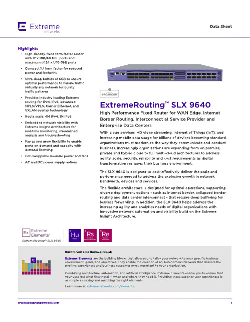
Extreme Networks SLX 9640高性能固定路由器商品介绍说明书
ExtremeRouting? SLX 9640
Built to Suit Your Business Needs Ext rem e Elem ent s are t he b uild ing b locks t hat allow you t o t ailor your net w ork t o your sp ecific b usiness environm ent , g oals, and ob ject ives. They enab le t he creat ion of an A ut onom ous Net w ork t hat d elivers t he p osit ive exp eriences and b usiness out com es m ost im p ort ant t o your org anizat ion.
W W W.EXTREMENETW
1
Flexib le Bo rd er Ro ut ing w it h Int ernet Scale, Ult ra-Deep Buffers,
MPLS and EVPN
The SLX 964 0 is a very p ow erful com p act d eep b uffer Int ernet b ord er rout er, p rovid ing a cost -efficient solut ion t hat is p urp ose-b uilt for t he m ost d em and ing service p rovid er and ent erp rise d at a cent ers and MA N/ WA N ap p licat ions. The rob ust syst em archit ect ure sup p ort ed by SLX-OS and a versat ile feat ure set includ ing IPv4 , IPv6, and MPLS/ VPLS w it h Carrier Et hernet 2.0 and OA M cap ab ilit ies t o p rovid e d ep loym ent flexib ilit y.
SCALANCE X101-1 商品说明书
24 V
6GK5101-1BB00-2AA3 Page 1/4
06/28/2018
Subject to change without notice © Copyright Siemens
● at DC / maximum
Supply voltage, current consumption, power loss Supply voltage ● external ● external Type of voltage / of the supply voltage Product component / fusing at power supply input Fuse protection type / at input for supply voltage Consumed current ● maximum Power loss [W] ● at DC / at 24 V
Compact 40 mm 125 mm 124 mm 0.55 kg
Yes Yes Yes
No No
FM3611: Class 1, Divison 2, Group A, B, C, D / T.., Class 1, Zone 2, Group IIC, T.. EN 600079-15 II 3 G EEx nA II T.. KEMA 06 ATEX 0021 X
Yes
Yes Yes Yes Yes Yes No 134 y
/snst
/simatic-net https:// /industry/infocenter /bilddb /cax https://
Security information
UL 60950-1, CSA C22.2 No. 60950-1 UL 1604 and UL 2279-15 (Hazardous Location), Class 1 / Division 2 / Group A, B, C, D / T.., Class 1 / Zone 2 / Group IIC / T.. EN 61000-6-3 EN 61000-6-4:2001 EN 61000-6-2:2001, EN 61000-6-4:2001 Yes Yes Yes
特斯拉电动汽车用户手册说明书

visit /zonedrooftopsystemsEf fi cient system operationTrane® Zoned Rooftop Systems take advantage of the newest technologies to improve comfort and increase ef fi ciency in small buildings.Trane rooftop units are available in a range of ef fi ciency tiers to match your budget and energy use goals. Variable-speed technologies areavailable to adjust compressor and fan speeds to more precisely match load requirements. This improves comfort in the space while reducing energy use at the same time. Zoned Rooftop Systems also offer integrated demand-controlled ventilation and economizer free cooling, further reducing energy use.To fully capitalize on the performance bene fi ts offered by these advanced technologies, integrated system control is a vital part of the solution. The Tracer® Concierge™ control system provides advanced optimization strategies to reduce energy use while improving occupant comfort, and is smart enough to let you know when service is needed to sustain optimal performance.Cost-effective, superior comfort for small buildingsTrane® Zoned Rooftop Systems are available in single- or multiple-zone con fi gurations to provide cost-effective comfort control for different areas of the building with varying comfort needs.The Tracer® Concierge™ control system offers the bene fi ts of a building automation system—without the complexity—and goes beyond managing individual rooms by operating the building smartly and ef fi ciently. It provides advanced capabilities for multiple-zone systems, is easy to use, and offers worry-free operation.Easy to design, install, and operatePackaged rooftop units provide cooling, heating, and ventilation in a single piece of equipment, simplifying system design, installation, and maintenance.Trane® Zoned Rooftop Systems use pre-engineered components and factory-installed controls that are designed to work together, contributing to on-time and on-budget installation. They use familiar components and are easy to recon fi gure if the space use changes in the future.The pre-packaged Tracer® Concierge™ system control panel, with its auto-discovery and con fi guration capabilities, allows for easier and faster installation. It includes an intuitive, easy-to-use operator interface on a 10-inch touchscreen display, along with mobile apps that allow the operator or service provider to manage the building from anywhere.The use of Air-Fi® Wireless controls results in faster project completion, increased sensor location fl exibility, greater reliability due to self-healing mesh networking, and easier relocation to accommodate future space use changes.ZO N E D R O O F TO P S YS T E M SLight commercial rooftop systems from TraneTrane® Zoned Rooftop Systems provide customers with affordable options for small buildings, to increase comfort and ef fi ciency, whilesimplifying maintenance.VAV terminal units (200 to 8000 cfm)• Trane fl ow ring provides unmatched air fl ow measurement accuracy and control • Durable, heavy-gauge air valve cylinder• modulating control• Air-Fi® Wireless communications • Retro fit dampers available for upgrading existing systemsTrane - by Trane Tech nologies (NYSE: TT), a global climate innovator - creates comfortable, energy efficient indoor environments for commercial and residential applications. For more information, please visit or .Trane h as a policy of continuous product and product data improvement and reserves th e righ t to ch ange design and specifications without notice. We are committed to using environmentally conscious print practices.All trademarks referenced are the trademarks of their respective owners.©2020 Trane. All Rights Reserved. ENV-SLB024C-ENNovember 5, 2020•single piece of equipment• able-speed fan control• Three tiers of effi ciency: standard, high, or ultra-high•••Pre-programmed, factory-installed ReliaT el™ DDC controls with wired or Air-Fi® Wireless communicationsAir-Fi® Wireless controls• Eliminates wires between equipment controllers and zone sensors, and between equipment and system controllers, allowing for faster installation, increased location fl exibility, and easier relocation• Self-healing wireless mesh and extended signal range maximize reliability• Supports open communication protocols through conformance with ASHRAE® Standard 135 (BACnet®/ZigBee®)• Up to four sensing functions in one zone sensor: temperature, humidity, occupan-cy, and CO 2• 15-year lifetime batteries。
Infoprint 250 導入と計画の手引き 第 7 章ホスト

SUBNETMASK
255.255.255.128
Type of service...............: TOS
*NORMAL
Maximum transmission unit.....: MTU
*LIND
Autostart.....................:
AUTOSTART
*YES
: xx.xxx.xxx.xxx
: xx.xxx.xxx.xxx
*
(
)
IEEE802.3
60 1500
: xxxx
48 Infoprint 250
31. AS/400
IP
MTU
1
1
IPDS TCP
CRTPSFCFG (V3R2)
WRKAFP2 (V3R1 & V3R6)
RMTLOCNAME RMTSYS
MODEL
0
Advanced function printing............:
AFP
*YES
AFP attachment........................:
AFPATTACH
*APPC
Online at IPL.........................:
ONLINE
FORMFEED
*CONT
Separator drawer......................:
SEPDRAWER
*FILE
Separator program.....................:
SEPPGM
*NONE
Library.............................:
BEA WebLogic Server Tuxedo Connector快速入门指南说明书

BEA WebLogicServer™WebLogic TuxedoConnector Quick StartGuideVersion 8.1Revised: March 28, 2003CopyrightCopyright © 2003 BEA Systems, Inc. All Rights Reserved.Restricted Rights LegendThis software and documentation is subject to and made available only pursuant to the terms of the BEA Systems License Agreement and may be used or copied only in accordance with the terms of that agreement. It is against the law to copy the software except as specifically allowed in the agreement. This document may not, in whole or in part, be copied, photocopied, reproduced, translated, or reduced to any electronic medium or machine readable form without priorconsent, in writing, from BEA Systems, Inc.Use, duplication or disclosure by the U.S. Government is subject to restrictions set forth in the BEA Systems License Agreement and in subparagraph (c)(1) of the Commercial Computer Software-Restricted Rights Clause at FAR52.227-19; subparagraph (c)(1)(ii) of the Rights in Technical Data and Computer Software clause at DFARS252.227-7013, subparagraph (d) of the Commercial Computer Software--Licensing clause at NASA FAR supplement 16-52.227-86; or their equivalent.Information in this document is subject to change without notice and does not represent a commitment on the part of BEA Systems. THE SOFTWARE AND DOCUMENTATION ARE PROVIDED “AS IS” WITHOUT WARRANTY OF ANY KIND INCLUDING WITHOUT LIMITATION, ANY WARRANTY OF MERCHANTABILITY OR FITNESS FOR A PARTICULAR PURPOSE. FURTHER, BEA Systems DOES NOT WARRANT, GUARANTEE, OR MAKE ANY REPRESENTATIONS REGARDING THE USE, OR THE RESULTS OF THE USE, OF THE SOFTWARE OR WRITTEN MATERIAL IN TERMS OF CORRECTNESS, ACCURACY, RELIABILITY, OR OTHERWISE. Trademarks or Service MarksBEA, Jolt, Tuxedo, and WebLogic are registered trademarks of BEA Systems, Inc. BEA Builder, BEA CampaignManager for WebLogic, BEA eLink, BEA Liquid Data for WebLogic, BEA Manager, BEA WebLogic Commerce Server, BEA WebLogic Enterprise, BEA WebLogic Enterprise Platform, BEA WebLogic Express, BEA WebLogic Integration, BEA WebLogic Personalization Server, BEA WebLogic Platform, BEA WebLogic Portal, BEA WebLogic Server, BEA WebLogic Workshop and How Business Becomes E-Business are trademarks of BEA Systems, Inc.All other trademarks are the property of their respective companies.ContentsConfiguring the WebLogic Tuxedo Connector. . . . . . . . . . . . . . . . . . . . . . . . . . . . . . . . .1-1 Build the Simpapp Example. . . . . . . . . . . . . . . . . . . . . . . . . . . . . . . . . . . . . . . . . . . .1-2Create a WTC Service . . . . . . . . . . . . . . . . . . . . . . . . . . . . . . . . . . . . . . . . . . . . . . . .1-3Create a Local Tuxedo Access Point . . . . . . . . . . . . . . . . . . . . . . . . . . . . . . . . . . . . .1-3Create a Remote Tuxedo Access Point. . . . . . . . . . . . . . . . . . . . . . . . . . . . . . . . . . . .1-4Create Exported Services . . . . . . . . . . . . . . . . . . . . . . . . . . . . . . . . . . . . . . . . . . . . . .1-4Create Imported Services . . . . . . . . . . . . . . . . . . . . . . . . . . . . . . . . . . . . . . . . . . . . . .1-5Target mySimpapp to the examplesServer . . . . . . . . . . . . . . . . . . . . . . . . . . . . . . . . .1-5Register TDOM1 as a WebLogic Server User . . . . . . . . . . . . . . . . . . . . . . . . . . . . . .1-5 Configuring Tuxedo. . . . . . . . . . . . . . . . . . . . . . . . . . . . . . . . . . . . . . . . . . . . . . . . . . . . . .1-6Run the Example . . . . . . . . . . . . . . . . . . . . . . . . . . . . . . . . . . . . . . . . . . . . . . . . . . . . . . . .1-7 WebLogic Server to Tuxedo Interoperability. . . . . . . . . . . . . . . . . . . . . . . . . . . . . . .1-7Tuxedo to WebLogic Server Interoperability. . . . . . . . . . . . . . . . . . . . . . . . . . . . . . .1-8WebLogic Tuxedo Connector Quick Start Guide iiiiv WebLogic Tuxedo Connector Quick Start GuideC H A P T E R1 WebLogic Tuxedo Connector Quick Start GuideNote:For more detailed information on how to configure the WebLogic Tuxedo Connector for this WebLogic Server Release, see the WebLogic Tuxedo Connector Programmer’sGuide at /wls/docs81/wtc_admin/index.html.The following sections describe how to use the WebLogic Server console to configure WebLogic Tuxedo Connector to allow WebLogic Server to interoperate with Tuxedo Releases 6.5 and higher:z Configuring the WebLogic Tuxedo Connectorz Configuring Tuxedoz Run the ExampleConfiguring the WebLogic Tuxedo ConnectorNote:This section summarizes how to configure the WebLogic Tuxedo Connector on a Windows platform. UNIX users can adapt the instructions by making appropriatesubstitutions such as replacing the “\” with “/” and “.cmd” with “.sh”.This example extends the Tuxedo simpapp application to run over Tuxedo Domains(TDomains). This allows clients of the TOUPPER service to run on either the Tuxedo server or the WebLogic Server examplesServer. The example provides the following services:z TOUPPER: A Tuxedo service that converts a string to upper case. A WebLogic Server clientinvokes the TOUPPER EJB and connects to the Tuxedo TOUPPER service.WebLogic Tuxedo Connector Quick Start Guide1-1z Tolower: A service implemented by an EJB in WebLogic Server. The client for theTolower service runs on Tuxedo.The following sections describe how to configure WebLogic Tuxedo Connector using theAdministration Console:z Build the Simpapp Examplez Create a WTC Servicez Create a Local Tuxedo Access Pointz Create a Remote Tuxedo Access Pointz Create Exported Servicesz Create Imported Servicesz Target mySimpapp to the examplesServerz Register TDOM1 as a WebLogic Server UserBuild the Simpapp ExampleNote:You may want to enable tracing to monitor WebLogic Tuxedo Connector. See Monitoring the WebLogic Tuxedo Connector located at/wls/docs81/wtc_admin/troubleshooting.html.Use the following steps to build the simpapp example:1.Boot your WebLogic examplesServer.2.Open a new shell window and set environment variables using theSAMPLES_HOME\domains\examples\setExamplesEnv.cmd file.3.Change directories to yourSAMPLES_HOME\server\examples\src\examples\wtc\atmi\simpapp directory.4.Build the wtc_toupper.jar file using ant. This will deploy the EJB on WebLogic Server.Enter the following command: ant5.Change directories to theSAMPLES_HOME\server\examples\src\examples\wtc\atmi\simpserv directory.6.Build the wtc_tolower.jar file. This will deploy the EJB on WebLogic Server. Enter thefollowing command: ant1-2WebLogic Tuxedo Connector Quick Start GuideConfiguring the WebLogic Tuxedo Connector unch the Administration Console in your browser. Use the following URL:http://your_machine:7001/console. Replace your_machine with the IP address for your machine or your machine name.8.In the navigation tree, Click Deployments→ EJB Modules and confirm that thewtc_tolower.jar and wtc_toupper.jar are deployed.Create a WTC ServiceUse the following steps to create and configure a WTC service using the WebLogic Server Console:1.Click Services in the navigation tree.2.Right-click WTC.3.Click Configure a New WTC Service.4.Enter the Name of your WTC service in the Name field. Example: mySimpapp5.Click Create.6.Your new WTC Service appears in the navigation tree.Create a Local Tuxedo Access PointNote:When configuring the Network Address for a local access point, the port number used should be different from any port numbers assigned to other processes. Example: Setting the Network Address to //mymachine:7001 is not valid if the WebLogic Serverlistening port is assigned to //mymachine:7001.Use the following steps to configure a local Tuxedo access point:1.Click mySimpapp in the navigation tree.2.Click the Contents tab.3.Select Local APs and click Configure a new Local Tuxedo Access Point.4.Enter the following values for the following fields on the General tab:Access Point: myLocalApAccessPoint ID: TDOM2Network Address: the network address and port of your local access pointWebLogic Tuxedo Connector Quick Start Guide1-3Example: //123.123.123.123:56785.Click Create.6.If you are connecting to a Tuxedo 6.5 domain, do the following:a.Click the Connections tab.b.Set the Interoperate field to Yes.c.Click Apply.Create a Remote Tuxedo Access PointUse the following steps to configure a remote Tuxedo access point:1.Click mySimpapp in the navigation tree.2.Click the Contents tab.3.Select Remote APs and click Configure a new Remote Tuxedo Access Point.4.Enter the following values for the following fields on the General tab:Access Point: myRemoteAPAccessPoint ID: TDOM1Local Access Point: myLocalApListen Address: the network address and port of your remote access pointExample: //123.123.123.123:12345.Click Create.Create Exported ServicesUse the following steps to configure an exported service:1.Click mySimpapp in the navigation tree.2.Click the Contents tab.3.Select Exported and click Configure a new Exported Service4.Enter the following values for the following fields on the General tab:1-4WebLogic Tuxedo Connector Quick Start GuideConfiguring the WebLogic Tuxedo ConnectorResource Name: TOLOWERLocal Access Point: myLocalApEJB Name: tuxedo.services.TOLOWERHomeRemote Name: TOLOWER5.Click Create.Create Imported ServicesUse the following steps to configure an imported service:1.Click mySimpapp in the navigation tree.2.Click the Contents tab.3.Select Imported and click Configure a new Imported Service4.Enter the following values for the following fields on the General tab:Resource Name: TOUPPERLocal Access Point: myLocalApRemote Access Point List: myRemoteAPRemote Name: TOUPPER5.Click Create.Target mySimpapp to the examplesServer1.Click mySimpapp in the navigation tree.2.Click the Target and Deploy tab.3.Click the checkbox for the examplesServer.4.Click ApplyRegister TDOM1 as a WebLogic Server UserUse the following steps to register TDOM1 as a WebLogic Server user:1.Click Security in the navigation tree.WebLogic Tuxedo Connector Quick Start Guide1-52.Click Realms.3.Click myRealm.4.Click on Users.5.Click the Configure a new User.6.In the General tab, do the following:a.Add TDOM1 in the Name field.b.Enter and validate a password.c.Click apply.Configuring TuxedoUse the following steps to configure your Tuxedo domain:1.Your PATH environment variable needs to include the path of your C compiler. Use set PATHto check the status and add the path if necessary.2.Copy the simpapp example from your Tuxedo installation and create a working Tuxedosimpapp directory.3.Change directories to your working Tuxedo simpapp directory.4.Set environment variables using the setEnv.cmd located at TUXDIR. Update the followingparameters:TUXDIR - base directory of the TUXEDO SoftwareAPPDIR - base directory of the sample program5.Build the clients:buildclient -o simpcl -f simpcl.cbuildserver -o simpserv -f simpserv.c -s TOUPPER6.Copy the ubbdomain and dom1config files from theSAMPLES_HOME\server\examples\src\examples\wtc\atmi\simpapp directory toyour Tuxedo simpapp directory.7.Copy the tolower.c file from theSAMPLES_HOME\server\examples\src\examples\wtc\atmi\simpserv directory toyour Tuxedo simpapp directory.1-6WebLogic Tuxedo Connector Quick Start GuideRun the Example8.Modify the ubbdomain for your Tuxedo environment. This includes setting the pathnamesfor APPDIR, TUXCONFIG, and TUXDIR and setting the machine name. Replace all <braced>items with information for your environment.Example:APPDIR="\home\me\simpapp"TUXCONFIG="\home\me\simpapp\tuxconfig""TUXDIR="\usr\tuxedo"9.Load the ubbdomain file: tmloadcf -y ubbdomain10.Modify the dom1config for your Tuxedo environment. This includes creating log devicesand updating the network addresses.Example:DMTLOGDEV="d:\my_apps\tlog"AUDITLOG="d:\my_apps\aud"TDOM1 NWADDR="//TuxedoMachine:1234"TDOM2 NWADDR="//WTCMachine:5678"11.Load the dom1config file.set BDMCONFIG=d:\mydomain\simpapp\bdmconfigdmloadcf -y dom1config12.Build the tolower clientbuildclient -f tolower.c -o tolower13.Boot the Tuxedo domaintmboot -yRun the ExampleRun each client to demonstrate interoperability between Tuxedo and WebLogic Server.WebLogic Server to Tuxedo InteroperabilityStart a WebLogic Server client from theSAMPLES_HOME\server\examples\src\examples\wtc\atmi\simpapp directory to invoke the TOUPPER EJB and connect to the Tuxedo TOUPPER service. Use the following command: ant runWebLogic Tuxedo Connector Quick Start Guide1-7The Tuxedo service replies to your WebLogic Server application with:Buildfile: build.xmlrun:[java][java] Beginning statefulSession.Client...[java][java] Creating Toupper[java][java] converting allcaps[java] converted to: ALLCAPS[java][java] End statefulSession.Client...[java]BUILD SUCCESSFULTuxedo to WebLogic Server InteroperabilityRun the tolower client from the Tuxedo simpapp directory to invoke the Tolower EJB and return the results to the client. Use the following command:tolower ALLSMALLThe WebLogic Server service replies to your Tuxedo client with:Returned string is: allsmall1-8WebLogic Tuxedo Connector Quick Start Guide。
千兆光猫用户手册说明书
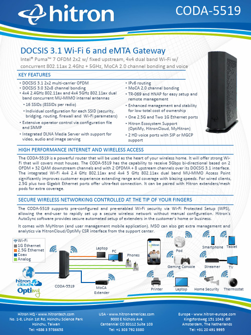
The CODA-5519is a powerful router that will be used as the heart of your wireless home.It will offer strong Wi-Fi that will covers most houses.The CODA-5519has the capability to receive 5Gbps bi-directional based on 2OFDM +32QAM downstream channels and with 2OFDMA +8upstream channels over its DOCSIS 3.1interface.The integrated Wi-Fi 4x42.4GHz 802.11ax and 4x45GHz 802.11ax dual band MU-MIMO Access Point significantly improves customer experience extending range and coverage with blazing speeds.For wired clients,2.5G plus two Gigabit Ethernet ports offer ultra-fast connection.It can be paired with Hitron extenders/mesh pods for extra coverage.•DOCSIS 3.1 2x2 multi-carrier OFDM •DOCSIS 3.0 32x8 channel bonding•4x4 2.4GHz 802.11ax and 4x4 5GHz 802.11ax dual band concurrent MU-MIMO internal antennas •16 SSIDs (8SSIDs per radio)•Individual configuration for each SSID (security, bridging, routing, firewall and Wi-Fi parameters)•Extensive operator control via configuration file and SNMP•Integrated DLNA Media Server with support for video, audio and image servingDOCSIS 3.1 Wi-Fi 6 and eMTA GatewayIntel® Puma™ 7 OFDM 2x2 w / fixed upstream, 4x4 dual band Wi-Fi w/ concurrent 802.11ax 2.4Ghz + 5GHz, MoCA 2.0 channel bonding and voice HIGH PERFORMANCE INTERNET AND WIRELESS ACCESSThe CODA-5519supports pre-configured and pre-enabled Wi-Fi security via Wi-Fi Protected Setup (WPS),allowing the end-user to rapidly set up a secure wireless network without manual configuration.Hitron's AutoSync software provides secure automated setup of extenders in the customer's home or business.It comes with MyHitron (end user management mobile application).MSO can also get extra management and analytics via HitronCloud/OptiMy CSR interface from the support center.SECURE WIRELESS NETWORKING CONTROLLED AT THE TIP OF YOUR FINGERSKEY FEATURES•IPv6 routing•MoCA 2.0 channel bonding•TR-069 and HNAP for easy setup and remote management•Enhanced management and stability for low total cost of ownership•One 2.5G and Two 1G Ethernet ports •Hitron Ecosystem Support (OptiMy, HitronCloud, MyHitron)•2 HD voice ports with SIP or MGCP supportTVStreamer Smartphone TabletThermostatHome Security LaptopCODA-5519Printer PCMoCA ExtenderPhonesWi-Fi1G Ethernet Analog2.5G Ethernet Coax PodLaptop Gaming ConsoleConnectivity•RF F-Type 75Ωfemale connector•2x RJ-45 Ethernet port 10/100/1000Mbps•1x RJ-45 Ethernet port 10/100/1000/2500Mbps•USB 3.0 type A connector with host interface•2x RJ-11 HD voice ports•EBBU jackManagement•Protocol support: TR-069, TFTP, SSHv2, SNMP v2C, v3•Web-based GUI control, configuration and management •Power-on self diagnostic•Hitron proprietary MIBs for extended support onDOCSIS, router management, Wi-Fi managementand MoCA management•app support•and back end supportReception-Demodulation•DOCSIS 3.1/3.0/2.0•DOCSIS 3.1 demodulation: Multi-carrier OFDM 16 to 4096QAM •DOCSIS 3.1 data rate: Up to 5Gps with 2 OFDM 192MHz downstream channels +32 QAM•DOCSIS 3.0 demodulation: 64QAM, 256QAM•DOCSIS 3.0 data rate: Up to 1.2Gbps with 32 bonded downstream channels•Frequency (edge-to-edge): 108-1218MHz and 258-1218 •Channel Bandwidth: 6MHz•Signal level: -15dBmV to 15dBmVTransmitter-Modulation•DOCSIS 3.1/3.0/2.0•DOCSIS 3.1 modulation: Multi-carrier OFDMA BPSK to 4096QAM •DOCSIS 3.1 data rate: Up to 700Mbps with OFDMA 96MHz upstream channels•DOCSIS 3.0 modulation: QPSK, 8QAM, 16QAM, 32QAM, 64QAM, and 128QAM (SCDMA only)•DOCSIS 3.0 data rate: Up to 320Mbps with 8 bonded upstream channels•Frequency: Fixed 5-85MHz•Upstream transmit signal level: +11 to 65dBmVMoCA 2.0 Reception / Transmitter-Modulation •Demodulation/ Modulation: BPSK, QPSK, 8QAM, 16QAM,32QAM, 64QAM, 128QAM, 256QAM, 512QAM, 1024QAM •PHY data rate: 700Mbps (baseline Mode) / 1400Mbps (bonding channel)•Throughput: 400+Mbps (baseline mode) / 500+Mbps (turbo mode, point to point) / 800Mbps (bonding channel)•Frequency (center frequencies): 1400-1625MHz•Channel bandwidth: 100MHz (baseline mode) / 225MHz (bonding channel)Voice•Protocol support: SIP or MGCP•2x 8kHz each HD voice•Audio codecs: G.711 (a-law and mu-law), G.722 (HD codec), G.723.1, G.726, G.728, and G.729Routing Support•Protocol support: IGMP v3 for IPTV service capability•MAC address filtering (IPv4/IPv6)•IP source/destination address filtering (IPv4/IPv6)•DHCP, TFTP and ToD clients (IPv4/IPv6)•DHCP server supports RFC 1541 (IPv4)•DHCPv6 obtains prefix from DHCPv6 server through prefix delegation•Firewall with stateful inspection (IPv4/IPv6)•Hacker intrusion prevention and detection•Application content filtering (IPv4/IPv6)•Complete NAT software implemented as per RFC 1631 with port and address mapping (IPv4)•DSLite support for IPv4 in-home support with IPv6 MSO backbone •6RD support for quick IPv6 deployment over IPv4 backbone •RIPv2 for static IP supportWireless•802.11a/b/g/n/ac/ax•4T4R 2.4GHz 11ax and 4T4R 5GHz 11ax dual band concurrent MU-MIMO with 1Gbps+4.8Gbps PHY rate•20/40/80/160MHz channel bandwidth•Up to 8 SSIDs for each frequency•Security: WPA-PSK/WPA2-PSK (TKIP/AES), WPA3, WAPI •QoS: WMM/WMM-PS•WPS (Wi-Fi Protected Setup) PBC, PIN•Airtime Fairness (ATF), Band Steering (BS)•Dynamic Frequency Selection (DFS)•Wi-Fi output power range: Max permitted by FCC/IC Electrical•Input power: 12VDC, 4A•Power adaptor: 100-240VAC, 50/60Hz•Power consumption: 4.92 (power saving), 22W (typ.), 38W (Max)•Support power outage for 24 hours on Hitron external battery •Surge protection: RF input sustains at least 4KVEthernet RJ-45 sustains at least 4KV Mechanical•Factory default reset button•WPS button•Dimensions: 74.3mm (W) x 251.5mm (H) x 230.8mm (D)•Weight: Weight: 1850 ±10gEnvironmental•Operating temperature: 0°C (32°F) ~ 40°C (104°F)•Operating humidity: 10% ~ 90% (Non-condensing)•Storage temperature: -40°C (-40°F) ~ 60°C (140°F) Compliance Certificates•RoHS compliant•FCC, IC, ULSPECIFICATIONS。
nustream-600i操作说明书

Tx mode:学习包发送模式,sync mode:同步模式。Group mode :群模式
Gap:在群模式中,数据流之间的间隙
Delay time after:数据流发送完等待时间
Transmit bu time/packet传输数据的总时间和大小
拟制:审核:批准:
日期:日期:日期:
卓翼科技股份
有限公司
nusteams-600i操作指导书
编号
页次
-nusteams-600i介绍
Nustreams-600i主要用于吞吐量相关的测试还有反复上下电启动测试。
二、软件设置
1设置管理网口
在图一中,根据PC机网卡上的MAC选择连接仪器的的管理网口。
图1
请确认好你需要用到的端口在Nuserver中是否激活,如图二。
图8
3.反复上下电启动测试
反复上下电测试,详见下文。
图2
2.建任务列表
勾选你所需要的端口后,四口EPON选择1 to many-uc,如下图所示,
图3
1 to Many-UC脚本编辑
PORTMAP
图中设置(0.6.1)建8条流,分别向八个端口的发送数据流,八个端口发数据流T
Up stream rate:上行速率,是例子中八个端口发送的数据流速率
v10更改部门更改人更改内容更改日期v10测试部首次发行20111108品管部商务部工程部采购部行政人事部开发部生产部结构部产品部pmc测试部会签部门会签人日期会签部门会签人日期测试部拟制
卓翼科技股份有限公司
工作指引
文件名称:nustream-600i操作指导书
文件版本:V1.0
PASCO Force Sensor (PS-2104) User Manual

Force Sensor (PS-2104)Force Sensor Bumper attachment Hook attachmentCart thumbscrew (M5 × 45 mm)Use to secure the sensor to a P ASCO dynamics cart. Rod clamp thumbscrew (1/4-20 × 0.75 in.)Use to secure the sensor to a rod, such as the 120 cm Stainless Steel Rod (ME-8741).Additional equipment required:•P ASPORT interface, such as the 550 Universal Interface (UI-5001) or 850 Universal Interface (UI-5000)•P ASCO Capstone or SP ARKvue data collection softwareGet the softwareY ou can use the sensor with SP ARKvue or P ASCO Capstone software. If you’re not sure which to use, visit/products/guides/software-comparison .SPARKvue is available as a free app for Chromebook, iOS, and Android devices. We offer a free trial of SP ARKvue and Capstone for Windows and Mac. T o get the software, go to/downloads or search for SPARKvue in your device’s app store.If you have installed the software previously, check that you havethe latest update:SPARKvueCheck for UpdatesPASCO CapstoneGo to Help > Check for Updates .Software setup1.T urn on SP ARKvue, then click Sensor Data .2.T urn on the P ASPORT interface if needed, then connectyour interface to SP ARKvue. For more specific details, see the manual for your chosen interface and the SP ARKvue online help.3.Plug the Force Sensor into one of the P ASPORT ports on the interface. SP ARKvue will automatically detect and identify the sensor.To collect data using SPARKvue:1.From the Select Measurements for Templates column,select the appropriate measurement for your experiment.2.From the Templates column, select Graph to enter the experiment screen. The display will automatically plot your selected measurement on the y-axis and time on the x-axis.3.Click Startto begin recording data.1.T urn on Capstone, then click Hardware Setup from the Tools palette.2.T urn on the P ASPORT interface if needed, then connect your interface to Capstone. For more specific details, see the manual for your chosen interface and the Capstone online help.3.Plug the Force Sensor into one of the P ASPORT ports on the interface. Capstone will automatically detect and identify the sensor.To collect data using Capstone:1.Double-click the Graph icon from the Displays palette to create a new Graph display.2.Click each <Select Measurement> box and select an appropriate measurement to assign that measurement to the associated axis.3.Click Recordto begin recording data.Zero the sensorPress the ZERO button on the front of the sensor to automatically adjust the sensor’s output to zero.Sample rateBy default, the sensor collects 20 samples per second. It can collect data as fast as 1000 samples per second (or up to 5000samples per second if connected to an 850 or 550 Universal Interface) or as slowly as one sample every 24 hours. Thesample rate can be changed in PASCO Capstone or SP ARKvue.Product Guide | 012-07297F1Hardware setupConnect bumper and hook attachmentsScrew the bumper or hook into the sensor as illustrated below.Sensor mountingTo mount the sensor on a PASCO cart:1.Align the hole in the sensor labeled Cart with one of the threaded holes in the accessory tray of the cart.2.Insert the included cart thumbscrew through the Cart hole in the sensor.3.Screw the thumbscrew into the threaded hole on top of thecart, as shown below.To mount the sensor on a rod:1.Slide the sensor onto a rod, as shown below.2.Tighten the thumbscrew to secure the rod in place.Software helpThe SPARKvue and P ASCO Capstone Help provide additional information on how to use this product with the software. Y oucan access the help within the software or online.SPARKvueSoftware:Online:/sparkvuePASCO CapstoneSoftware: Help > P ASCO Capstone Help Online: /capstoneSpecifications and accessoriesVisit the product page at /product/PS-2104 to view the specifications and explore accessories. Y ou can also download experiment files and support documents from the product page.Experiment filesDownload one of several student-ready activities from the P ASCO Experiment Library. Experiments include editable student handouts and teacher notes. Visit /freelabs/PS-2104.Technical supportNeed more help? Our knowledgeable and friendly T echnical Support staff is ready to answer your questions or walk you through any issues.Chat Phone 1-800-772-8700 x1004 (USA)+1 916 462 8384 (outside USA) Email*****************Force Sensor | PS-21042Regulatory informationLimited warrantyFor a description of the product warranty, see the Warranty and Returns page at /legal.CopyrightThis document is copyrighted with all rights reserved. Permission is granted to non-profit educational institutions for reproduction of any part of this manual, providing the reproductions are used only in their laboratories and classrooms, and are not sold for profit. Reproduction under any other circumstances, without the written consent of P ASCO scientific, is prohibited.TrademarksP ASCO and P ASCO scientific are trademarks or registered trademarks of PASCO scientific, in the United States and in other countries. All other brands, products, or service names are or may be trademarks or service marks of, and are used to identify, products or services of, their respective owners. For more information visit /legal.Product end-of-life disposalThis electronic product is subject to disposal and recycling regulationsthat vary by country and region. It is your responsibility to recycle yourelectronic equipment per your local environmental laws and regulationsto ensure that it will be recycled in a manner that protects human healthand the environment. T o find out where you can drop off your waste equipment for recycling, please contact your local waste recycle or disposal service, or the place where you purchased the product. The European Union WEEE (Waste Electronic and Electrical Equipment) symbol on the product or its packaging indicates that this product must not be disposed of in a standard waste container.Product Guide | 012-07297F3。
Beacon Global Technology BT-PNA-MB 通讯网关模块产品说明书
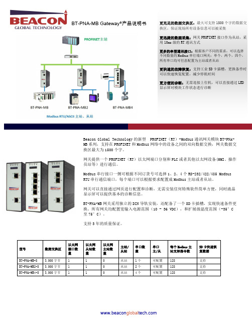
BT-PNA-MB Gateway ®产品说明书更充足的数据交换区:最大可支持1500个字的数据交换区,保证现场所有设备信息可以被采集更迅捷的数据采集:网关PROFINET 接口作为从站,采用10ms 级的RT 通讯方式更多的串型通讯接口:根据客户不同的要求,可以选择不同数量的Modbus 串行端口网关:单个,两个,四个,所有串口均可任意配置为主站或者从站更快速的故障恢复:支持工业SD 卡插槽,更换备件时可以快速恢复配置,减少停机时间更方便的诊断:无需连接上位机,可以直接通过LED 显示屏对模块工作状态进行诊断Beacon Global Technology 的新型 PROFINET (RT )-Modbus 通讯网关模块BT-PNA-MB 系列,支持在PROFINET 和Modbus 网络中的设备之间的双向数据交换,网关数据交换区最大为1500个字。
网关提供一个PROFINET (RT )以太网端口分别和PLC 或者其他以太网设备(HMI 、操作员站等)进行通信。
Modbus 串行接口一侧可根据不同订货号可选择1、2、4个RS-232/422/485 Modbus RTU 串行通信端口,每个端口可以根据要求配置成Modbus 主站或者从站。
网关可以直接通过网页进行配置和诊断,无需安装任何特殊软件简单方便,同时液晶显示屏可以提供基本的诊断信息。
BT-PNA-MB 网关采用独立的DIN 导轨安装,还配备了一个SD 卡插槽,实现快速备件更换。
所有网关均配置宽输入电源范围(10 - 36 VDC ),和扩展级温度范围(-35°C 至75°C)。
支持3年的质量保证。
BEACON GLOBAL TECHNOLOGYUSA|SHANGHAI|BEIJING|CHENGDU美国|上海|北京|成都中国(上海)自由贸易试验区美盛路 117号3幢5层563室 北京市昌平区立水桥北方明珠大厦3号楼 19层 1917室 中国深圳市宝安区西乡街道中粮云大厦三栋1606 - B四川省成都市天府新区华阳街道龙灯山路299号心怡德盛苑22栋辽宁省大连市高新园区软件园软景E 居2#2209。
LTE典型信令过程

NAS:PDN connectivity request
Authentication and NAS security procedure
S6a: Update Location request
S11: Modify bearer response S1AP: Path Switch Response
X2AP: UE Context Release
Flush DL Buffer
Data Forwarding End Marker
Switch DL Path
S1 Handover
➢This type of handover takes place when there is no X2 connectivity between source eNB and target eNB.
S10: Forward SRNS Context Notification
UE Detach from old cell and sync to new cell
S10: Forward SRNS Context Ack
S1AP: MME Status Transfer
RRC: Connection Reconfiguration Complete
➢The release of resources at the source side is directly triggered from the target eNB.
UE
S-eNB
RRC: Measurement Control
BEACON 云平台快速启动手册说明书
BEACON云平台快速启动手册目录云平台简介 (3)云平台账户注册 (5)电脑端配置云平台 (6)利用OPEN VPN完成远程设备接入 (9)通过云平台远程访问现场设备 (28)安卓系统安装OPEN VPN (32)PC端和微信端远程数据监控功能 (34)联系我们 (47)BEACON 云平台简介更强大的功能:通过BEACON云平台和智能通讯模块可以远程对现场设备进行程序更新、调试诊断、变量监控等工作,历史数据存储,阀值监控,可以大大减少前往现场的次数,节约维护和使用成本。
更强丰富的设备:客户可以利用传统的PC或者各类移动客户端(手机,平板电脑)等访问云平台,同时云平台可以连接BEACON的多款智能通讯设备:BC系列工业路由器、云终端。
更迅捷的数据采集:BEACON云平台采用先进的数据传输优化技术,使平台内的数据交换速度大为提升。
更稳定的网络结构:由经BC系列云终端连接至BEACON云平台的现场设备,具备断网即时自动上线的功能,同时具备定时自动监测云端链接状态的功能,最大程度保证了通讯的稳定性。
更具兼容性的应用:支持多种工业以太网驱动,适合于不同品牌的控制系统1)简单易用,安全可靠BEACON CLOUD由两部分组成:BEACON云平台服务器以及BEACON智能通讯设备。
只需三步就可以完成对于远程设备的监控和维护:第一步,登录官网,注册BEACON CLOUD账号,并且添加相应的硬件设备;第二步,简单配置PC、手机或者平板电脑的参数;第三步,配置需要通讯的硬件终端设备参数。
BEACON CLOUD将会提供7*24小时全天候的服务,多重加密验证,保证数据传输的安全性,并可以记录生成设备在线历史报告方便查询。
2)远程维护,节约成本工程师可以在任何互联网覆盖范围内,通过BEACON CLOUD云平台以及BEACON所提供的智能云终端实现对远端多台现场设备(包括控制系统,RTU,仪表多种设备)进行远程维护和监控,对控制系统进行程序更新、远程调试诊断、变量监控等工作。
Weblogic日志分析

§1Weblogic日志分析BEA公司是weblogic的厂商,他们做的日志比我们更专业,我非常肯定他们的分析。
在这里,我就不重复BEA公司对肇庆电网营销系统的再分析了,只是从开发的角度,对一些问题做一点补充。
§1.1BEA-101083BEA的分析非常正确,关于解决方法有一点补充。
这个也可能是网络的原因导致的,因此建议对于出现慢的地区的网络进行检查,确保网络有足够的带宽与速度。
§1.2BEA-101017补充一点,这可能是程序内部的代码不优化,导致有大量数据产生,从日志来看,可能下面这些组件需要优化:ponent.ar.cmp_ar_servicelocationponent.msflow.cmp_ms_ex_flow_getoutponent.aparchive.cmp_ag_meterassetponent.chg.cmp_chg_arrear_queryponent.aparchive.cmp_ag_servicelocationponent.flow.cmp_flow_worklistponent.chg.cmp_chg_bank_chgmonth日志分析1、日志中BEA相关打印信息类汇总 (3)2、各BEA代码分类明细 (3)3、BEA代号分析 (5)3.1、错误类代码分析 (5)3.2.Debug类分析 (9)3.3.Alert类分析 (10)3.4.Waining类分析 (11)4、BEA代码段分析 (12)5、日志总体分析 (17)说明:日志时间段:May 15, 2007 9:02:37 AM CST to May 15, 2007 3:42:03 PM CSTServer :weblogic_a2logname weblogic_a2.log time:2007-5-15 15:42 size:27,275,777K以下为针对日志中与weblogic相关信息进行分析,特别是大量中间件信息与BEA相关代码进行统计及打印信息及特点进行描述。
Polycom CX8000 for Microsoft Lync 产品质保指南说明书
August 2014 | 3725-68088-001/A1 Polycom ® CX8000 for Microsoft ® Lync ® Product Warranty GuideUse the table below to view a summary of the warranty periods applicable to Polycom’s Limited Warranty for the Polycom ® CX8000 for Microsoft ® Lync ® room system. The terms and conditionsapplicable to Polycom’s Limited Warranty are listed on the following page and are also included in the documentation packaged with the Polycom product.Product Warranty for Accessories for the Polycom CX8000 Room System Accessories for the Polycom CX8000 Room System 1 Warranty Period Codec 2 years Front of Room Camera 2 years Center of Room Camera 1 year Speakers 2 years Console/Touch Control 21 year Wall mount2 years 1 Disk drives and any other moving or rotating mechanical parts, pan/tilt heads, and power supplies are covered for a period of one (1) year. 2Polycom warranties the control panel for 1 year but warranties the overlay that enables the touch capability for 90 days only.Polycom CX8000 for Microsoft Lync Product Warranty GuidePolycom, Inc.2 THE TERMS AND CONDITIONS APPLICABLE TO POLYCOM’S LIMITED WARRANTY ARE AS SET FORTH BELOW (AND ARE ALSO INCLUDED IN THE DOCUMENTATION PACKAGED WITH NEW POLYCOM PRODUCTS):LIMITED HARDWARE WARRANTY. Polycom warrants to the end user (“You” or “Your”) that the hardware product will be free from def ects in workmanship and materials, under normal use and service, for one year, or such longer period as Polycom may announce publicly from time to time for particular products, from the date the product is shipped by Polycom or its Authorized Reseller. Polycom’s sole obli gation under this express warranty shall be, at Polycom’s option and expense, to repair the defective product or part, deliver to You an equivalent product or part to replace the defective item, or if neither of the two foregoing options is reasonably available, Polycom may, in its sole discretion, refund to You the purchase price paid for the defective product. All products that are replaced will become the property of Polycom. Replacement products or parts may be new or reconditioned. Polycom warrants any replaced or repaired product or part for ninety (90) days from shipment, or the remainder of the initial warranty period, whichever is longer. Products returned to Polycom must be sent prepaid and packaged appropriately for safe shipment, and it is recommended that they be insured or sent by a method that provides for tracking of the package. Responsibility for loss or damage does not transfer to Polycom until the returned item is received by Polycom. The repaired or replaced item will be shipped to You, at Polycom’s expense, not later than thirty (30) days after Polyc om receives the defective product, and Polycom will retain risk of loss or damage until the item is delivered to You.LIMITED SOFTWARE WARRANTY. Polycom warrants to You that the software product (whether pre-loaded on hardware or provided as a standalone product) will perform substantially in accordance with the accompanying documentation for a period of ninety (90) days from the date the hardware product is shipped by Polycom or its Authorized Reseller or the software is initially download by You, as applicable.Polycom’s sole obligation under this express warranty shall be, at Polycom’s option and expense, to repair or replace the def ective software, or if neither of the two foregoing options is reasonably available, Polycom may, in its sole discretion, refund to You the purchase price paid for the defective product. Any replacement software will substantially conform to the accompanying documentation and be warranted for the remainder of the original warranty period or thirty (30) days, whichever is longer.EXCLUSIONS. Polycom will not be liable under this limited warranty if its testing and examination disclose that the alleged defect ormalfunction in the product does not exist or results from:• Failure to follow Polycom’s installation, operation, or m aintenance instructions;• Unauthorized product modification or alteration;• Unauthorized use of common carrier communication services accessed through the product;• Abuse, misuse, negligent acts or omissions of Yours and persons under Your control; or• Acts of third parties, acts of God, accident, fire, lighting, power surges or outages, or other hazards.WARRANTY EXCLUSIVE. IF A POLYCOM PRODUCT DOES NOT OPERATE AS WARRANTED ABOVE, YOUR SOLE REMEDY FOR BREACH OF THAT WARRANTY SHALL BE REPAIR, REPLACEMEN T, OR REFUND OF THE PURCHASE PRICE PAID, AT POLYCOM’S OPTION. POLYCOM DOES NOT WARRANT THAT YOUR USE OF THE SOFTWARE WILL BE UNINTERRUPTED OR ERROR FREE, OR THAT ALL DEFECTS IN THE SOFTWARE WILL BE CORRECTED. FOR SOFTWARE PRODUCTS, YOU ASSUME FULL RESPONSIBILITY FOR THE SELECTION OF THE SOFTWARE PRODUCT TO ACHIEVE YOUR INTENDED RESULTS AND FOR THE INSTALLATION, USE AND RESULTS OBTAINED FROM THE SOFTWARE PRODUCT. TO THE FULL EXTENT ALLOWED BY APPLICABLE LAW, THEFOREGOING WARRANTIES AND REMEDIES ARE EXCLUSIVE AND ARE IN LIEU OF ALL OTHER WARRANTIES, TERMS, ORCONDITIONS, EXPRESS OR IMPLIED, EITHER IN FACT OR BY OPERATION OF LAW, STATUTORY OR OTHERWISE, INCLUDING WARRANTIES, TERMS, OR CONDITIONS OF MERCHANTABILITY, FITNESS FOR A PARTICULAR PURPOSE, SATISFACTORY QUALITY, CORRESPONDENCE WITH DESCRIPTION, AND NON-INFRINGEMENT, ALL OF WHICH ARE EXPRESSLY DISCLAIMED. POLYCOM NEITHER ASSUMES NOR AUTHORIZES ANY OTHER PERSON TO ASSUME FOR IT ANY OTHER LIABILITY INCONNECTION WITH THE SALE, INSTALLATION, MAINTENANCE OR USE OF ITS PRODUCTS.SUPPORT & SERVICE AGREEMENTS. Product support and services are covered under a separate services agreement. If You purchased Your product from a Polycom Authorized Reseller, contact the Authorized Reseller for information about support and service agreementsapplicable to Your product. For information on Polycom service, go to the Polycom website , products and services menu, or call 1-800-765-9266, outside the US call 1-408-526-9000, or Your local Polycom Office, as listed on the Polycom website.LIMITATION OF LIABILITY. TO THE FULL EXTENT ALLOWED BY APPLICABLE LAW, POLYCOM EXCLUDES FOR ITSELF AND ITS SUPPLIERS ANY LIABILITY, WHETHER BASED IN CONTRACT OR TORT (INCLUDING NEGLIGENCE), FOR INCIDENTAL,CONSEQUENTIAL, INDIRECT, SPECIAL, OR PUNITIVE DAMAGES OF ANY KIND, OR FOR LOSS OF REVENUE OR PROFITS, LOSS OF BUSINESS, LOSS OF INFORMATION OR DATA, OR OTHER FINANCIAL LOSS ARISING OUT OF OR IN CONNECTION WITH THE SALE, INSTALLATION, MAINTENANCE, USE, PERFORMANCE, FAILURE, OR INTERRUPTION OF ITS PRODUCTS, EVEN IF POLYCOM OR ITS AUTHORIZED RESELLER HAS BEEN ADVISED OF THE POSSIBILITY OF SUCH DAMAGES, AND LIMITS ITS LIABILITY TO REPAIR, REPLACEMENT, OR REFUND OF THE PURCHASE PRICE PAID, AT POLYCOM’S OPTION. THIS DISCLAIMER OF LIA BILITY FOR DAMAGES WILL NOT BE AFFECTED IF ANY REMEDY PROVIDED HEREIN SHALL FAIL OF ITS ESSENTIAL PURPOSE.DISCLAIMER. Some countries, states, or provinces do not allow the exclusion or limitation of implied warranties or the limitation of incidental or consequential damages for certain products supplied to consumers, or the limitation of liability for personal injury, so the above limitations and exclusions may be limited in their application to You. When the implied warranties are not allowed to be excluded in their entirety, they will be limited to the duration of the applicable written warranty. This warranty gives You specific legal rights which may vary depending on applicable local law.Polycom, Inc.6001 America Center DriveSan Jose CA 95002USA© 2014 Polycom, Inc. All rights reserved. POLYCOM® and the names and marks associated with Polycom's products are trademarks and/or service marks of Polycom, Inc., and are registered and/or common law marks in the United States and various other countries.。
Sync Scan 产品说明书

TABLE OF CONTENTS PageSETTING UP SYNC SCAN2 SYNC SCAN DASHBOARD3 WIFI3 BULK UPLOAD VIDEO3 HELP DESK PORTAL3 DISINFECTING KIOSK3 PREPARING THE AREA FOR SYNC SCAN4 TEMPERATURE ADJUSTMENT 5 PREPARING THE PERSON BEING EVLAUATED6 HOW TO MOBILE DEVICE PICTURE UPLOAD7 FACIAL RECOGNITION IMAGE REQUIREMENTS8 SOFTWARE UPDATES9 CREATE GROUPS FOR REPORTS9 ATTENDANCE REPORTS10 HIGH TEMPERATURE EMAIL & TEXT ALERTS12 RENAME KIOSK(S)12 ADD USERS/ADD ADMIN USERS13 EDIT PERSON13 DELETE PERSON14SETTING UP SYNC SCANHardware Kiosk Setup: https:///watch?v=-_AolYfbtl8Install Sync Scan + Register:https:///watch?v=KU4_J31fGRM •Connect To WIFI •Uninstall MIPS/DCMIPSRegister Device: Kiosk will display a 9-digit code after Sync Scan is installed and Opened. Enter code to register the device at syncscan.cloud (Username/Password Will Be Emailed).•Install Sync Scan: s24.io/ssapkCLEANING KIOSK SCREENS●Gently Wipe Down Screen With a Screen Cleaner Sprayed a Few Times Onto a New Clean, Non-Abrasive Cloth (Microfiber is Great).●CDC-Recommended Disinfectant Solutions Safe for Screens + Kiosk Frame 1) Household Bleach Solution (1/3 Cup of Bleach Per Gallon of Water)2) Isopropyl Alcohol (≤ 70% Alcohol)Disinfecting Your Kiosk 1. To prepare for disinfecting the touchscreen, power down the device (if possible) or ensure your on-screen software can tolerate false touches while you clean.2. Dampen a new clean, non-abrasive cloth (microfiber is great) with a disinfectant listed above. Ensure excess liquid is squeezed from the cloth. 3. Disinfect the surfaces by wiping them with the cloth and allow the surface to dry.SYNC SCAN DASHBOARD + WIFI + BULK UPLOADSync Scan Dashboard : log into syncscan.cloud to see all temperature scans andadjust all kiosk settings.Sync Scan Dashboard Bulk Upload Tutorial: https:///watch?v=3nA0OCniVGcSubmit Issue Tickets: https:///hc/en-us/restricted?return_to=https%3A%2F%%2Fhc&locale=en-usConnect To/Change WIFI Network: (1) Right Click To Exit (2) Settings (3) Select Wi-Fi (4) Select Wi-Fi Network (2.4 GHz) & Enter PasswordPREPARING THE AREA WHERE YOU WILL USE THE TEMPERATURE KIOSK ●Room temperature should be 68-76 °F (20-24 °C) and relative humidity 10-50percent.●Try to control other items that could impact the temperature measurement:○Avoid reflective backgrounds (for example, glass, mirrors, metallic surfaces) to minimize reflected infrared radiation.○Use in a room with no draft (movement of air), out of direct sunlight and away from radiant heat (for example, portable heaters, electricalsources).○Avoid strong lighting (for example, incandescent, halogen and quartz tungsten halogen light bulbs).TEMPERATURE ADJUSTMENT It is best to use the thermal kiosk at the temperatures of and between68-76 °F (20-24°C). However, if using the kiosk outside or in temperatures above or below 68-76 °F (20-24 °C)you can adjust the temperature under <Settings> 'Temperature adjustment’ in the Sync Scan Dashboard syncscan.cloud. If it is cold outside you can reduce the ‘Temperature adjustment ’ number andincrease the ‘Temperature adjustment ’ number if warmer outside/in the sun. As the temperature outside changes, you will need to go back into the dashboard and adjust the 'Temperature adjustment ' number accordingly.For the most accurate Temperature adjustment use a handheld noncontact thermometer on a test person to see what temperature should be read on the thermal kiosk. Change the ‘Temperature adjustment ’ in the Sync Scan Kiosk accordingly. For example, if the kiosk is reading temperatures high on average test a person’s temperature with a handheld noncontact thermometer. If the handheld thermometer show the test person at a normal 98 °F while the kiosk shows 100°F adjust the kiosk’s ‘Temperature adjustment ’ to -2 (see image below).This thermal kiosk measures the surface skin temperature, which is usually lower than a temperature measured orally. Thermal imaging systems must beadjusted properly to correct for this difference in measurements. The most accurate temperature scans are taken at 1 to 1.5 feet distance from the thermal kiosk.PREPARING THE PERSON BEING EVALUATEDThe person handling the system should make sure the person being evaluated:•Does not have any face obstructions before measurement (such as a dark mask, glasses, hat, headband, or scarf), the person's hair is pulled away from the face, and the person’s face is clean and dry.•Does not have a higher or lower face temperature from wearing excessive clothing or head covers (for example, headbands, bandanas) or from using facial cleansing products (for example, cosmetic wipes).•Has waited at least 15 minutes in the measurement room or 30 minutes after exercising, strenuous physical activity, bathing, or using hot or cold compresses on the face.MOBILE DEVICE PICTURE UPLOADFACIAL RECOGNITION IMAGE REQUIREMENTSPLEASE NOTE: Facial recognition is most accurate when ALL ‘people’ have clear and accurate pictures uploaded to their profile. The algorithm learns facesovertime to become more accurate.SOFTWARE UPDATESCREATE GROUPS FOR REPORTSATTENDANCE REPORTSSEARCH TEMP CHECK-INS BY GROUPHIGH TEMPERATURE EMAIL & TEXT ALERTSRENAME DEVICESADD USERS/ADD ADMIN USERS1) EDIT PERSON2) EDIT PERSONDELETE PERSONIt is best to use the thermal kiosk at the temperatures of and between 68-76 °F (20-24 °C). However, if using the kiosk outside or in temperatures above or below 68-76 °F (20-24 °C)you can adjust the temperature under <Settings> 'Temperature adjustment.’ We recommend using a handheld contactless thermometer to calibrate the thermal kiosk. Seepages 3-5 for how to prepare the room and people being evaluated.SYNC CLOUD PORTAL SECURITYSync Cloud sits on a Digital Ocean Server.We do not share customer data with any third parties,other than our infrastructure provider.We require TLS with strong ciphers for all communication,and our database and storage are encrypted at rest.Our infrastructure provider is ISO/IEC27001:2013certified,and the facility in which our servers are hosted is SSAE16SOC-2and SOC-3compliant.PLEASE NOTE:Sync Scan is not a medical device. This device is not FDA approved and is intended for initial body temperature measurements for triage use.It can not be the sole or primary method of diagnosing COVID-19 or any other condition.Indication of an elevated body temperature should be confirmed with secondary evaluation methods such as a clinical grade contactthermometer.。
OpenText LoadRunner 2023 产品说明书

Product FlyerLoadRunner Professional and LoadRunner Enterprise 2023 License Bundles Community bundles and license bundles available for OpenT ext™ LoadRunner Professional and OpenT ext™ LoadRunner Enterprisemunity Bundles (Free of Charge) Bundle Name DescriptionC ommunity 50 Vusers for all protocols, except for T emplates and GUIM obile UI U nlimited Vusers for the TruClient—Native Mobile protocol.N ote: This bundle requires an OpenT ext Mobile Center license. For more details, see: https:///software/customer-technical-support-services License BundlesBundle Name Protocols.Net Record/Replay M icrosoft .Net.Net+ D atabase O DBCOracle—2 Tier D evelopment S DK Unit T est—NUnit, Junit Selenium, UFT Developer*G UI U nified Functional T esting (UFT)J ava C loud for AWSJava Record ReplayJava over HTTP Kafka M obile and IoT D evWebJMeterGatlingWeb—HTTP/HTMLTruClient—Mobile WebSMP (SAP Mobile Platform)MQTT (Internet of Things)CoAP (Internet of Things) N etwork D NS (Domain Name Resolution)FTP (File Transfer Protocol)IMAP (Internet Message Access Protocol)LDAP (Listing Directory Service)MAPI (Microsoft Exchange)POP3 (Post Office Protocol) SMTP (Simple Mail T ransfer Protocol)Tuxedo Windows Sockets (Winsock)O racle E-Business D evWebJMeterGatlingOracle NCAOracle—WebSiebel—WebWeb—HTTP/HTML Continued on next page* UFT Developer support is for LoadRunner Enterprise only. Learn more athttps:///productsBundle Name ProtocolsR emote Access C itrix ICARTE (Remote T erminal Emulator)T eradici PCoIPR emote Desktop M icrosoft RDP (Remote Desktop Protocol)R ich Internet A pplications S elenium**T ruClient—Mobile Web T ruClient—WebS AP S AP GUISAP—WebSMP (SAP Mobile Platform)S OA U FT API (converts Unified Functional T esting API tests to become load-enabled) Web ServicesT emplates (T emplate virtual users are manually developed and do not include record capability)C VuserC++ .NET C# .NET Java Vuser VB .NETW eb D evWebJMeterGatlingWeb—HTTP/HTMLW eb 2.0D evWebJMeterGatlingSelenium**UFT API (converts Unified Functional T esting API tests to become load-enabled)T ruClient—Mobile WebT ruClient—WebWeb—HTTP/HTMLWeb Services**S elenium support is for LoadRunner Professional 2021 and above, as well as LoadRunner Enterprise 2021 R1 and aboveEnterprise SuiteIncludes the following load testing and performance testing protocol bundles: Mobile UI, .NET Record/Replay, Database, Development, Java, Mobile and IoT, Network, Oracle E-Business, Remote Access, Remote Desktop, Rich Internet Applications, SAP, SOA, Web and Web 2.0. Learn more at/opentext261-000111-002 | O | 07/23 | © 2023 Open T ext。
NAD CS1 网络音频流媒体设备说明书

1. CONNECTHDMI IN 1OPTICAL 1DIGITAL AUDIO INDownload the latest CS1 Owner’s manual from the Manuals/Downloads tab of /product/NAD-CS-1-network-audio-streamer For further support regarding the operation of your CS1, visit Install Google Home by downloading the App from your respective devices’ App Stores.2. DOWNLOAD3. NETWORK CONNECTIONConnect your NAD CS1 to your home network via Wired or Wireless connection.A. WIRED CONNECTIONUsing an Ethernet cable (not supplied), connect one end to CS1’s LAN port and the other end directly to your Home network or router.B. WIRELESS CONNECTIONConfigure wireless network connection using the smartphone or tablet that applies to you. Connect CS1 to your wireless network using any of the following three methods.1Wireless Accessory Configuration (WAC) using iOS device2Google Home App using iOS device3Google Home App using Android deviceCondition: CS1 must be at hot spot mode (LED Power Indicator alternately flashing red and green). CS1 default setting is at hot spot mode.NOTEThe following procedures and details may change over time without notice. Always check the NAD CS1 product page for the latest updates.1 WIRELESS ACCESSORY CONFIGURATION (WAC) USING iOS DEVICEWireless Accessory Configuration (WAC) setup mode is supported by iOS application. At WAC setup mode, network name and password are not required for the CS1 to be connected to your network.a Select Settings menu of your iOS device.b Go to Wi-Fi and select the network you would like to use with your CS1.c Under SETUP NEW AIRPLAY SPEAKER, select your CS1 speaker indicated by NAD-CS1xxxx where xxxx corresponds to the last 4 digits of the Machine AccessControl (MAC) address of your CS1. The complete MAC address can be found on the bottom panel of your CS1.d When AirPlay Setup screen comes up, select Next. Note that you can also customize the name of your CS1 by entering desired name in the line item SpeakerName.e Airplay Setup will proceed automatically. Follow or monitor screen prompts until setup is completed. Select Done to exit setup mode.2 GOOGLE HOME USING iOS DEVICEa Open Google Home App using your iOS device.b Select Set up NAD CS1 devices or similar.c Choose a home where your NAD CS1 will be assigned and then select Next.d Nearby devices found will be shown. Choose or confirm the device you would like to setup.e Choose NAD-CS1xxxx where xxxx corresponds to the last 4 digits of the Machine Access Control (MAC) address of your CS1. Select Next.f Select Yes if you heard the sound as your NAD CS1 gets connected. Follow screen prompts.g Choose a location for your NAD CS1 – this will help name your CS1. You may also select Add a custom room name to enter preferred name for your CS1. SelectNext.h Connect to Wi-Fi. Choose the Wi-Fi network you would like to use with your CS1. Enter the Wi-Fi password.i Follow or execute instructions on the screen prompts until Finish Tutorial is selected. CS1 setup is now complete.3 GOOGLE HOME USING ANDROID DEVICEa Open Google Home App using your Android device.b Select + icon on the upper left corner of the App.c Under Add to home, select Set up device.d Select New device.e Choose a home where your NAD CS1 will be assigned and then select Next.f Nearby devices found will be shown. Choose or confirm the device you would like to setup.g Choose NAD-CS1xxxx where xxxx corresponds to the last 4 digits of the Machine Access Control (MAC) address of your CS1. Select Next.h Select Yes if you heard the sound as your NAD CS1 gets connected. Follow screen prompts.i Choose a location for your NAD CS1 – this will help name your CS1. You may also select Add a custom room name to enter preferred name for your CS1. SelectNext.j Connect to Wi-Fi. Choose the Wi-Fi network you would like to use with your CS1. Enter the Wi-Fi password or use saved password for the Wi-Fi network you selected.k Follow or execute instructions on the screen prompts until xxx Speaker is Ready is displayed and a Tutorial clip about Casting is selected or skipped. CS1 setup is now complete.©2023 NAD ELECTRONICS INTERNATIONAL, A DIVISION OF LENBROOK INDUSTRIES LIMITEDAll rights reserved. NAD and the NAD logo are trademarks of NAD Electronics International, a division of Lenbrook Industries Limited.No part of this publication may be reproduced, stored or transmitted in any form without the written permission of NAD Electronics International.CS1 QSG V11 - 03/23。
Best Power BestLink SNMP WEB Adapter 用户手册说明书
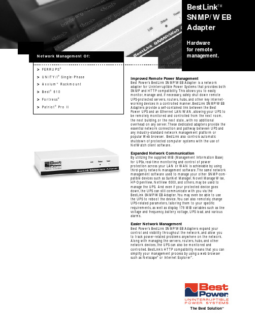
the next building,or the next state...with no additionaloverhead on any server.These dedicated adapters provide the essential network connection and pathway between UPS and any industry-standard network management platform or popular Web browser.BestLink also controls automatic shutdown of protected computer systems with the use of NetWatch client software.Expanded Network CommunicationBy utilizing the supplied MIB (Management Information Base)for UPSs,real-time monitoring and control of powerprotection across your LAN or WAN is achievable by using third-party network management software.The same network management software used to manage your other SNMP-com-patible devices such as SunNet Manager,Novell Manage Wise,HP-OpenView,NetView 6000,and others,may be used to manage the UPS.And even if your protected device goes down,the UPS can still communicate with you via theBestLink SNMP/WEB Adapter.Y ou may even be able to use the UPS to reboot the device.Y ou can also remotely change UPS-related parameters,tailoring them to your specificrequirements,as well as display 176 MIB variables such as line voltage and frequency,battery voltage,UPS load,and various alarms.Easier Network ManagementBest Power’s BestLink SNMP/WEB Adapters expand your control and visibility throughout the network,and allow you to track power-related problems anywhere on the network.Along with managing the servers,routers,hubs,and other network devices,the UPS can also be monitored andcontrolled.BestLink’s HTTP compatibility means that you can simplify your management process by using a web browser such as Netscape ®or Internet Explorer ®.>FERRUPS ®Network Management Of:BestLink TMSNMP/ WEB AdapterHardware for remote management.The Best Solution ™BestLink TMSNMP/ WEBAdapterModel BestLink™ SNMP/WEB Adapter SNMP-3Part No.IPK-0318IPK-0319IPK-0320IPK-0033Description Provides both SNMP and HTTP compatibility to single-phase UPS applications.Supporting UPS-to-EthernetExternal Unit Internal integration for three-phaseCard UPS applications.Network Connections Ethernet 10BaseT One Ethernet 10BaseT,one 10Base2.The Best Solution™An Invensys Company LTP-0267RL ©2000,Best Power.All rights reserved.00-001 2/00。
- 1、下载文档前请自行甄别文档内容的完整性,平台不提供额外的编辑、内容补充、找答案等附加服务。
- 2、"仅部分预览"的文档,不可在线预览部分如存在完整性等问题,可反馈申请退款(可完整预览的文档不适用该条件!)。
- 3、如文档侵犯您的权益,请联系客服反馈,我们会尽快为您处理(人工客服工作时间:9:00-18:30)。
CID Name MustBeSatisfieCategorySubclausePageLineTopicIssueID2212Bahr,MichaelYes Technical11C.12.2.2.327424MAC M-BS2241Bahr,MichaelYes Technical11C.12.4.22761MAC M-BS2239Bahr,MichaelNo Technical11C.12.4.2.12768MAC M-BS2234Bahr,MichaelYes Technical11C.12.4.2.227654MAC M-BS2254Bahr,MichaelYes Technical11C.12.4.2.527815MAC M-BS2253Bahr,MichaelNo Technical11C.12.4.2.527817MAC M-BS2262Bahr,MichaelYes Technical11C.12.4.4.127915MAC M-BS2261Bahr,MichaelNo Technical11C.12.4.4.127922MAC M-BS2267Bahr,MichaelYes Technical11C.12.4.4.327958MAC M-BSComment Proposed Change Resoluti on StatusI am still convinced that it is advantageous, if the Neighbor Offset method only calculates the Offset and Clock drift, but does not do any TSF adjustments. TSF adjustments should be specified as a separate procedure which is called by the 11s mechanisms that need it (MCCA, MBCA, although MBCA has it's own mechanism to deal with TBTT drifting). The two main advantages are:- Power Save does not need clock drift adjustment (TSF adjustment). What power save needs is to know the TBTT of a neighbor mesh STA in order to wake up at the right time. This can be easily achieved by calculating the offset and clock drift. Furthermore, the requirement to do the TSF adjustment as currently specified requires the power save nodes to stay awake longer and to do additional computations. This requires power that could be saved.make 11C.12.2.2.3 clock drift adjustment a separate mechanismand move it to clause 11C.12.2a.extend the neighbor offset synchronization method with clockdrift calculation.reference clock drift adjustment procedure in all 11s mechanismsthat need it or use it (MCCA,MBCA)DeferThe beacon timing advertisement comes out of the blue. The overview was talking about MBCA, but did not introduce a beacon timing advertisement. Furthermore,11C.12.4.2.1 starts with a very specific detail, the maintenance of the status number. But where does this status number come from?1) add a overview description of MBCA including the beacon timing advertisement into clause11C.12.4.1 Overview.2) reorganize 11C.12.4 in such a way that the reader can follow the specification and that there is a line of thought that develops by building on the information of the previous subclauses within 11C.12.4 MBCA.The condition is difficult to understand, especially the when. It is always set to 0 and than incremented to 1 every time? Also some English "since it has updated"Make condition easy to understand. Improve wording.Principle"calculated for the first time since the latest update of the status number" is not understandable. Furthermore, it seems to contradict "time predicted from the previous TBTT" in line 45.correct this.How can a mesh STA obtain the beacon reception timing (i.e. the time when a beacon has been received) from a beacon timing element? The fields in the beacon timing information of the beacon timing element are the Neighbor STA ID, the Neighbor Last Beacon Time which indicates a TBTT, and the Neighbor Beacon Interval. But I guess, it is the beacon timing information stored at this neighbor change "beacon reception timing" into "TBTT" or what it actually means. Maybe beacon timing information?This sentence (last sentence of this paragraph) is more of a general nature. In any way, it does not belong to the procedures done in lieu of the reception of a beacon timing element. It does not say what to do when a beacon timing element is received. Instead it talks about general procedures to be done when Move this to the general clause of MBCA. In clause 11C.12.4.2.5 Receiver's procedure, only normative text that directly follows out of the reception of the beacon timing element belongs in this clause.The mesh STA should not parse the Beacon Timing element. It might contain only incomplete information, and there might be none available when it wants to parse it.parse or analyse or what other better verb the beacon timing information.coming later is not a sufficient differentiation. Especially in a collision situation, the TBTTs might be the provide complete differantiation criterionSetting the TBTT Adjusting field in the Mesh Configuration element has serious implications to the synchronization method performed at the neighbor mesh STAs. Therefore, it should be only set when an adjustment is really performed. It is a bad idea to set this flag when the mesh STA is only collecting information and is only doing internal move step a) to the correct place, that is, just before the actual TBTT adjustment.Resolution Detail SubmissionUpdated(to editor)ResponseStatusAccept_RejectDate#MotionEditStatusMBCA text structure:Replace"is initialized with 0 and incremented by 1 before transmitting a frame containing the Beacon Timing element when the mesh STA encountered any of the following events since it has updated the status number previously:"with"is initialized with 0. It is incremented by 1 before transmitting a frame containing the Beacon Timing element, when the mesh STA encounteredWording:MBCA text structure:Wording:Edited Edit Notesin Draft。
