ISL28448中文资料
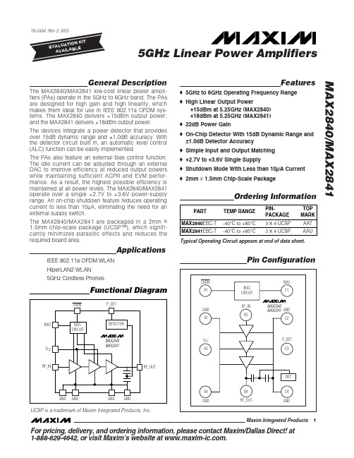
MAX2840-MAX2841中文资料
Stresses beyond those listed under “Absolute Maximum Ratings” may cause permanent damage to the device. These are stress ratings only, and functional operation of the device at these or any other conditions beyond those indicated in the operational sections of the specifications is not implied. Exposure to absolute maximum rating conditions for extended periods may affect device reliability.
元器件交易网
19-2494; Rev 2; 8/03 EVAALVUAAILTAIOBNLEKIT
5GHz Linear Power Amplifiers
MAX2840/MAX2841
General Description
The MAX2840/MAX2841 low-cost linear power amplifiers (PAs) operate in the 5GHz to 6GHz band. The PAs are designed for high gain and high linearity, which makes them ideal for use in IEEE 802.11a OFDM systems. The MAX2840 delivers +15dBm output power, and the MAX2841 delivers +18dBm output power.
开关电源uc2844中文资料详细(uc2844引脚功能

开关电源uc2844中文资料详细(uc2844引脚功能应用电子电路发表于 2018-01-02 09:15:50开关电源uc2844采用双列直插8脚封装;电流脉冲宽度调制器,输入电压范围5~30V,最大功耗=1W,振荡器频率≥500kHz,基准电压=5V,电压调整率=6mV,电流调整率=6mA,输出端最大电流=1000mA,最大占空度=95%。
内含振荡器、高增益误差放大、锁存器、推挽输出电路等,具有过压、过流检测保护功能。
uc2844引脚功能uc2844工作原理电源电路采用了电流PWM控制模式,就使反激式电路形成了稳定性很好的双环路反馈(输出直流电压隔离取样反馈外回路和初级线圈充磁峰值电流取样反馈内回路)控制系统,就可以通过开关电源的PWM调制器迅速调整脉冲占空比,从而在每一个周期内对前一个周期的输出电压和初级线圈充磁峰值电流进行有效调节,达到稳定输出电压的目的。
这种反馈控制电路的最大特点是:在输入电压和负载电流变化较大时,具有更快的动态响应速度,自动限制负载电流,补偿电路简单。
反激电路适应于小功率开关电源。
单端反激式开关电源是以开关管的周期性导通与截止为主要特征。
开关导通时,在变压器的原边线圈一侧储存电能,与副边线圈相连的超快恢复二极管处于反偏压状态,所以二极管截止,在变压器次级线圈中无电流流过,即没有能量传递给负载。
开关管截止时,变压器副边电感线圈中的电压极性反转,使二极管导通,给输出电容充电,同时负载也有电流流过。
uc2844应用电路下图是为变频器设计的反激式开关电源的典型电路,主要包括交流输入整流电路,反激式开关电源功率级电路(有PWM控制器、MOS管、变压器及整流二极管组成),RCD缓冲电路和反馈网络。
其中PWM控制芯片采用UC2844。
UC2844是电流模式控制器,芯片内部具有可微调的振荡器(能进行精确的占空比控制)、温度补偿的参考基准、高增益误差放大器、电流取样比较器。
反激式开关电源典型设计。
芯片ISL84684英文数据手册

PART NO. (BRAND)
TEMP. RANGE (°C)
PACKAGE
PKG. DWG. #
ISL84684IR (684IR)
-40 to 85 10 Ld 3x3 Thin DFN L10.3x3A
ISL84684IR-T (684IR)
-40 to 85 10 Ld 3x3 Thin DFN L10.3x3A Tape and Reel
Applications
• Battery powered, Handheld, and Portable Equipment - Cellular/mobile Phones - Pagers - Laptops, Notebooks, Palmtops
• Portable Test and Measurement • Medical Equipment • Audio and Video Switching
ISL84684 (TDFN, MSOP) TOP VIEW
V+ 1 NO1 2 COM1 3
IN1 4 NC1 5
10 NO2 9 COM2 8 IN2 7 NC2 6 GND
NOTE: 1. Switches Shown for Logic “0” Input.
Truth Table
LOGIC
PIN NC1 and NC2 PIN NO1 and NO2
®
Data Sheet
June 2004
ISL84684
FN6088
Ultra Low ON-Resistance, Low Voltage, Single Supply, Dual SPDT Analog Switch
The Intersil ISL84684 device is a low ON-resistance, low voltage, bidirectional, dual single-pole/double-throw (SPDT) analog switch designed to operate from a single +1.65V to +3.6V supply. Targeted applications include battery powered equipment that benefit from low RON (0.25Ω) and fast switching speeds (tON = 14ns, tOFF = 6ns). The digital logic input is 1.8V logic-compatible when using a single +3V supply.
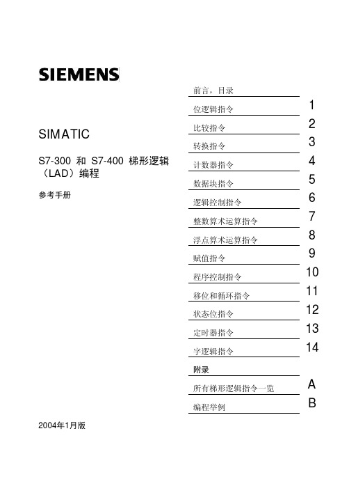
★★STEP7梯形图编程手册(中文)_带书签
其它支持
如果你有任何技术问题,你可以与当地的西门子代表处或代理商联系。 /automation/partner /service
培训中心
西门子公司还提供有许多培训课程,介绍 SIMATIC S7 自动化系统。详情请与您所在地区 的培训中心联系,或与德国纽伦堡(邮编 D90327)的总部培训中心联系: 德 国: +49 (911) 895 - 3200 北 京:(010) 6439 2860 上 海:(021) 3220 0899 - 306 广 州:(020) 8732 0088 - 2279 武 汉:(027) 8548 6688 - 6601 哈尔滨:(0451) 239 3129 重 庆:(023) 6382 8919 - 3002
传真: +1 (0) 770 740 3699
传真: +86 10 64 74 74 74
E-Mail: isd-callcenter@
E-Mail: @
GMT:
-5:00
GMT: +8:00
SIMATIC 热线和授权热线的使用语言一般为德语和英语。
前言,目录
位逻辑指令
1
SIMATIC
比较指令
2
转换指令
3
S7-300 和 S7-400 梯形逻辑
计数器指令
4
(LAD)编程
数据块指令
5
参考手册
逻辑控制指令
6
整数算术运算指令
7
浮点算术运算指令
8
赋值指令
9
程序控制指令
10
移位和循环指令
11
状态位指令
12
定时器指令
13
字逻辑指令
uc2844中文资料
开关电源uc2844带有双列直插8引脚封装;电流脉冲宽度调制器的输入电压范围为5-30v,最大功耗= 1W,振荡器频率≥500KHz,参考电压= 5V,电压调节率= 6MV,电流调节率= 6mA,最大输出电流= 1000mA,最大占空比周期= 95%。
它包含振荡器,高增益误差放大器,锁存器,推挽输出电路等。
具有过压,过流检测保护功能。
UC2844引脚功能开关电源uc2844中文信息的详细信息(uc2844引脚功能_工作原理_应用电路)开关电源uc2844中文信息的详细信息(uc2844引脚功能_工作原理_应用电路)uc2844如何工作电源电路采用电流PWM控制模式,使反激电路形成稳定的双环反馈控制系统(输出直流电压隔离采样反馈外环和初级线圈励磁峰值电流采样反馈内环)控制系统通过开关电源的PWM调制器调整脉冲占空比,从而在每个周期中调整前一个周期的脉冲占空比。
可以有效地调整初级线圈的输出电压和励磁峰值电流,以稳定输出电压。
该反馈控制电路的主要特点是:当输入电压和负载电流变化较大时,动态响应速度更快,自动限制负载电流,补偿电路简单。
反激电路适用于低功率开关电源。
单端反激式开关电源的特征在于开关管的周期性导通和截止。
当开关接通时,功率存储在变压器的初级线圈的一侧,并且与次级线圈连接的超快恢复二极管处于反向偏置状态,因此该二极管被切断,并且没有流过变压器次级线圈的电流,即没有能量传递到负载。
当开关断开时,变压器次级电感线圈中的电压极性反转,从而使二极管导通并为输出电容器充电。
同时,有电流流过负载。
UC2844应用电路下图显示了为变频器设计的典型反激式开关电源电路,主要包括交流输入整流器电路,反激式开关功率级电路(由PWM控制器,MOS晶体管,变压器和整流器二极管组成),RCD缓冲电路和反馈网络。
PWM控制芯片为uc2844。
UC2844是电流模式控制器。
它具有一个微调振荡器(可以精确控制占空比),一个用于温度补偿的参考基准,一个高增益误差放大器和一个电流采样比较器。
UC2844AD1中文资料
Tamb = 125°C, 1000Hrs
(note 2)
ISC Output Short Circuit
OSCILLATOR SECTION
fOSC Frequency
Tj = 25°C
∆fOSC/∆V Frequency Change with Volt. VCC = 12V to 25V
∆VREF/∆T Frequency Change with Temp. TA = Tlow to Thigh
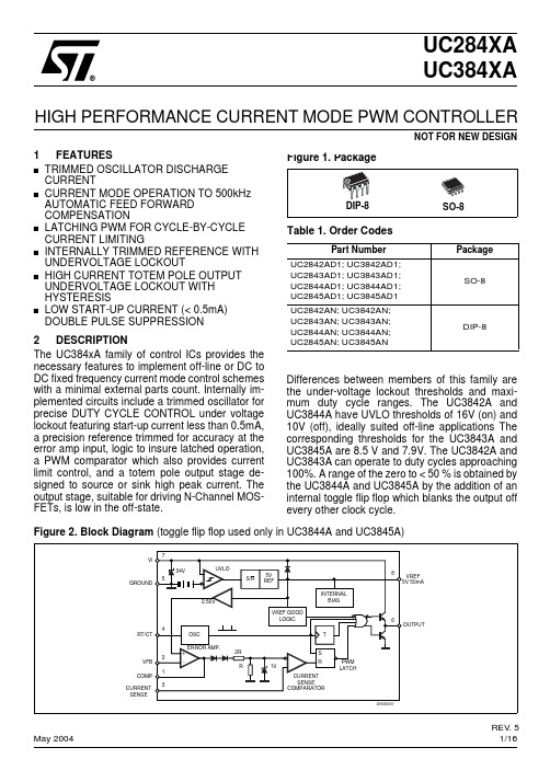
Figure 2. Block Diagram (toggle flip flop used only in UC3844A and UC3845A)
7 Vi
5 GROUND
4 RT/CT
2 VFB
1 COMP CURRENT 3 SENSE
34V
UVLO
S/R
5V REF
2.50V
VREF GOOD LOGIC
■ LOW START-UP CURRENT (< 0.5mA) DOUBLE PULSE SUPPRESSION
2 DESCRIPTION
The UC384xA family of control ICs provides the necessary features to implement off-line or DC to DC fixed frequency current mode control schemes with a minimal external parts count. Internally implemented circuits include a trimmed oscillator for precise DUTY CYCLE CONTROL under voltage lockout featuring start-up current less than 0.5mA, a precision reference trimmed for accuracy at the error amp input, logic to insure latched operation, a PWM comparator which also provides current limit control, and a totem pole output stage designed to source or sink high peak current. The output stage, suitable for driving N-Channel MOSFETs, is low in the off-state.
SG2844J中文资料

F 10-pin
— — — — — — — —
Cer. Flatpack
L 20-pin
— — — —
Ceramic LCC
SG3844M SG3845M SG2844M SG2845M — — — — —
SG1844L SG1845L SG1844L/883B SG1845L/883B
SG1844Y/883B SG1844J/883B SG1845Y/883B SG1845J/883B SG1844Y/DESC SG1844J/DESC
K E Y F E AT U R E S
s OPTIMIZED FOR OFF-LINE CONTROL s LOW START-UP CURRENT (<1mA) s AUTOMATIC FEED FORWARD COMPENSATION s TRIMMED OSCILLATOR DISCHARGE CURRENT s PULSE-BY-PULSE CURRENT LIMITING s ENHANCED LOAD RESPONSE CHARACTERISTICS s UNDER-VOLTAGE LOCKOUT WITH 6V HYSTERESIS (SG1844 only) s DOUBLE PULSE SUPPRESSION s HIGH-CURRENT TOTEM-POLE OUTPUT s INTERNALLY TRIMMED BANDGAP REFERENCE s 500kHz OPERATION s UNDERVOLTAGE LOCKOUT SG1844 - 16 volts SG1845 - 8.4 volts s LOW SHOOT-THROUGH CURRENT <75mA OVER TEMPERATURE
in4148中文资料_数据手册_参数
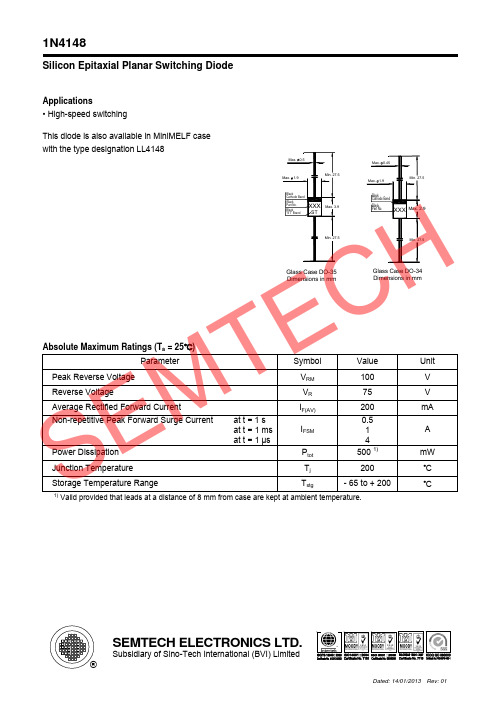
SEMTECH ELECTRONICS LTD.
Subsidiary of Sino-Tech International (BVI) Limited ®
Dated: 14/01/2013 Rev: 01
1N4148
Admissible power dissipation versus ambient temperature
Max. 0.5 Max. 1.9
Min. 27.5
Max. 0.45 Max. 1.9
Min. 27.5
Black Cathode Band
Black Part No.
Black "ST" Brand
XXX
ST
Max. 3.9
Black Cathode Band
Black Part No.
XXX Max. 2.9
Reverse Recovery Time at IF = 10 mA to IR = 1 mA, Irr = 0.1 x IR, VR = 6 V, RL = 100 Ω
Thermal Resistance Junction to Ambient Air
Vfr
-
trr
-
RthA
-
Rectification Efficiency at f = 100 MHz, VRF = 2 V
ηV
0.45
1) Valid provided that leads at a distance of 8 mm from case are kept at ambient temperature.
4
2.5
4 0.35 1)
-
pF V
ns K/mW
SM-284B中文资料
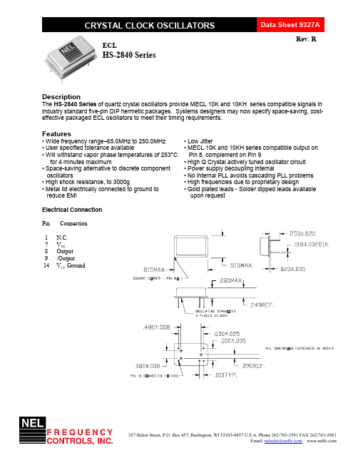
357 Beloit Street, P.O. Box 457, Burlington, WI 53105-0457 U.S.A. Phone 262/763-3591 FAX 262/763-2881Email: nelsales@ECLHS-2840 SeriesDescriptionThe HS-2840 Series of quartz crystal oscillators provide MECL 10K and 10KH series compatible signals in industry standard five-pin DIP hermetic packages. Systems designers may now specify space-saving, cost-effective packaged ECL oscillators to meet their timing requirements.Features• Wide frequency range–65.0MHz to 250.0MHz • User specified tolerance available• Will withstand vapor phase temperatures of 253°C for 4 minutes maximum• Space-saving alternative to discrete component oscillators• High shock resistance, to 3000g• Metal lid electrically connected to ground to reduce EMI • Low Jitter• MECL 10K and 10KH series compatible output on Pin 8, complement on Pin 9• High Q Crystal actively tuned oscillator circuit • Power supply decoupling internal• No internal PLL avoids cascading PLL problems • High frequencies due to proprietary design• Gold plated leads - Solder dipped leads available upon requestElectrical ConnectionPin Connection1 N.C. 7 V EE 8 Output 9 /Output 14 V CC GroundCRYSTAL CLOCK OSCILLATORSData Sheet 9327ARev. REmail: nelsales@ HS-2840 Series ContinuedECLOperating Conditions and Output CharacteristicsElectrical CharacteristicsParameter Symbol Conditions Min Typical MaxFrequency----------65.0MHz -----250.0MHz Duty Cycle ----- @V CC -1.29V45/55% -----55/45%Logic 0 (2)V OL ----- V CC -1.95V -----V CC -1.60V Logic 1(2)V OH ----- V CC -1.02V ----- V CC -0.74V Rise & Fall Time tr,tf 20-80%V O with 50 ohm load to V CC -2V ----- 1.0 ns 1.5 ns Tpd (4)-----------0.5 ns -----+0.5 ns Jitter, RMS (3)-------------------- 5 psec Frequency Stability (1)dF/F Overall conditions including:-100ppm -----+100ppmvoltage, calibration, temp.,10 yr aging, shock, vibrationGeneral CharacteristicsParameterSymbolConditions Min Typical Max Supply Voltage V EE ----- -5.46V -5.2V -4.94V Supply Current I EE50 ohm termination 0.0 mA -----80 mA To 2.00V below V CCOutput currentI O Low level Output Current 0.0 mA -----±50.0 mA Operating temperature T A ------ 0°C -----70°C Storage temperature T S ----- -55°C -----125°C Power Dissipation P D ---------------437 mW Lead temperature T L Soldering, 10 sec. ----- -----300°C Load50 Ohm to V CC -2V or Thevenin Equivalent, Bias Required Start-up timet S ---------- 2 ms10 msEnvironmental and Mechanical CharacteristicsMechanical Shock Per MIL-STD-202, Method 213, Condition E Thermal Shock Per MIL-STD-833, Method 1011, Condition AVibration0.060" double amplitude 10 Hz to 55 Hz, 35g’s 55Hz to 2000 Hz Soldering Condition 300°C for 10 secondsHermetic Seal Leak rate less than 1 x 10⁻⁸ /sec of heliumESD SensitivityHuman Body Model per ON Semiconductor 10kH series ECL: 500V min .Footnotes:Rev. RCRYSTAL CLOCK OSCILLATORSData Sheet 9327A。
SW-284中文资料

Intermodulation Intercept Point (for two-tone input power up to +5 dBm) Intercept Points IP2 IP3 0.5 – 2.0 GHz +60 +45 dBm Typ 0.05 GHz +53 +35 dBm Typ Bias Power Control Voltages Vin Low (0) Vin Hi (1) -5 VDC @ 2 mA Max +5 VDC @ 1 mA Max 0.0 to 1.5V @ 1 µA Max 3.5 to 5.0V @ 1 µA Max
0.75 Sq (19.0)
0.125 (3.18) 0.100 5 Places (2.54) 0.015 ±.004 12 Places (0.38 ± 0.10) 0.150 MAX (3.81)
Operating Characteristics
Impedance Switching Characteristics Trise, Tfall (10% to 90% RF) Ton, Toff (50% CTL to 90%/10% RF) Transients (In-Band) Input Power for 1 dB Compression 0.5 – 2.0 GHz 0.05 GHz 50 Ohms Nominal 3.0 ns Typ 180 ns Typ 150 mV Typ 23 dBm Typ 21 dBm Typ
Guaranteed Specifications11 Specifications
Frequency Range Insertion Loss VSWR (RF Common) VSWR (RF1-RF6 On) VSWR (RF1-RF6 Terminated) Isolation
74LS248中文资料

[1]: 测试条件中的“最小”和“最大”用推荐工作条件中的相应值。
http://www.elecfans.com
VOH输出高电平电压
Vcc=最小,VIL=最大, VIH=2V,IOH=最大
Io 输出电流 a~g
Vcc=最小,VIL=最大, VIH=2V,Vo=0.58V
VOL输出低电平电压
Vcc=最小,VIL=最 大,VIH=2V,IOL=最大
54 74
II最大输入电压时输 入电流
除 BI/RBO
Vcc=最大
存储温度 ………………………………………….
功能表:
5.5V 7V 1mA
-55~125℃ 0~70℃ -65~150℃
推荐工作条件:
电源电压 Vcc
54 74
输入高电平电压ViH
输入低电平电压
54
ViL
74
输出高电平电流 IOH
a~g /BI(/RBO)
54248/74248 最小 额定 最大
4.5
5
5.5
4.75
5
5.25
2
0.8 0.8
-400
-200
54LS248/74LS248 最小 额定 最大
4.5
5
5.5
4.75
5
5.25
2
0.7 0.8
-100
-50
单位 V V V
uA
http://www.elecfans.com
IC资料查询网站:
电子工程技术论坛:
输出低电平电流 IOL
a~g
IOL 6.4mA 2mA 6mA
VO(OFF) 5.5V 5.5V 5.5V
PD 265mW 125mW 125mW
IN4148中文资料
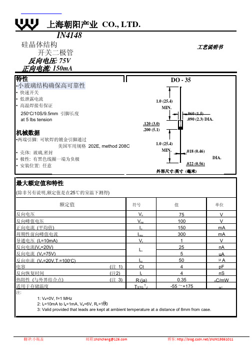
nA
5
uA
反向电流 (VR=20V,TJ=100oC)
IR2
50
A
电容
(注 1)
Ct
4
pF
反向恢复时间
(注2)
IF
4
nS
热阻性 (与外界结合点) 适用于存储温度
注:
(注 3)
R(ja) TSTG,TJ
0.35 -55 +175
oC/mW
oC
1: VR=0V, f=1 MHz 2: IF=10mA to IR=1mA, VR=6V, RL=100 3: Valid provided that leads are kept at ambient temperature at a distance of 8mm from case.
翻译:小瓶盖
邮箱:zhzhchang@
博客: /zhzht19861011
• 壳体: 玻璃,密封 • 极性: 有黑色线圈一端为负极 • 安装位置: 任意
DO - 35
1.0 (25.4) MIN.
.120 (3.0) .200 (5.1)
.060 (1.5) .090 (2.3) DIA.
1.0 (25.4) MIN.
.018 (0.46)
.022 (0.56) 外形尺寸:英寸 (毫米)
上海朝阳产业 CO., LTD.
IN4148
硅晶体结构 开关二极管
反向电压: 75V 正向电流: 150mA
工艺说明书
特性 •小玻璃结构确保高可靠性
• 快速开关 • 低泄露电流 • 高温焊接有保证
250oC/10S/9.5mm 引脚长度 at 5 lbs tension
机械数据
高压防闩锁型48通道多路复用器

修订历史
2013年3月—修订版B至修订版C 更改表5和表6 ................................................................................ 8 表7中ADG5408峰值电流从370 mA变为435 mA; ADG5409峰值电流从275 mA变为300 mA; 回流焊峰值温度(无铅)从260(+0/−5)°C变为“依据 JEDEC J-STD-020”........................................................................ 9 更改图25、图26和图29 ............................................................ 16
license is granted by implication or otherwise under any patent or patent rights of Analog Devices.
Trademarks and registered trademarks are the property of their respective owners.
±15 V双电源 ............................................................................. 3 ±20 V双电源 ............................................................................. 4 12 V单电源................................................................................ 5 36 V单电源................................................................................ 6 每通道连续电流,Sx或D ...................................................... 8
ADM2483中文资料_数据手册_参数

REVISION HISTORY
uc2844中文资料
开关电源uc2844带有双列直插8引脚封装;当前脉冲宽度调制器的输入电压范围为5-30v,最大功耗= 1W,振荡器频率≥500KHz,参考电压= 5V,电压调节率= 6MV,电流调节率= 6mA,最大输出电流= 1000mA,最大占空比周期= 95%。
它包含振荡器,高增益误差放大器,锁存器,推挽输出电路等。
具有过压,过流检测保护功能。
UC2844引脚功能uc2844如何工作电源电路采用电流PWM控制方式,使反激电路形成稳定的双环反馈控制系统(输出直流电压隔离采样反馈外环和初级线圈励磁峰值电流采样反馈内环)控制系统通过开关电源的PWM调制器调整脉冲占空比,从而在每个周期中调整前一个周期的脉冲占空比。
可以有效地调整初级线圈的输出电压和励磁峰值电流,以稳定输出电压。
该反馈控制电路的主要特点是:当输入电压和负载电流变化较大时,动态响应速度更快,自动限制负载电流,补偿电路简单。
反激电路适用于低功率开关电源。
单端反激式开关电源的特征在于开关管的周期性导通和截止。
当开关接通时,功率存储在变压器的初级线圈的一侧,并且与次级线圈连接的超快恢复二极管处于反向偏置状态,因此该二极管被切断,并且没有流过变压器次级线圈的电流,即没有能量传递到负载。
当开关断开时,变压器次级电感线圈中的电压极性反转,从而使二极管导通并为输出电容器充电。
同时,有电流流过负载。
UC2844应用电路下图显示了为变频器设计的典型反激式开关电源电路,主要包括交流输入整流器电路,反激式开关功率级电路(由PWM控制器,MOS晶体管,变压器和整流器二极管组成),RCD缓冲电路和反馈网络。
PWM控制芯片为uc2844。
UC2844是电流模式控制器。
它具有一个微调振荡器(可以精确控制占空比),一个用于温度补偿的参考基准,一个高增益误差放大器和一个电流采样比较器。
IS485中文资料
1 0.9
Relative threshold illuminance
0.8
0.7 2
0.6
0.5 0
E VHL(IS485 ), EVLH ( IS486 ) = 1 at Vcc= 5V
5
10
15
20
Supply voltage V cc ( V )
Fig. 5 Low Level Output Voltage vs.
Rise time Fall time
IS485 IS486
Symbol V OL V OH I CCL I CCH
E VHL
IS485
IS486
IS485 IS486 IS485 IS486 IS485 IS486
E VLH
E VLH /E VHL E VHL /E VLH
t PHL
t PLH tr tf
IS485/IS486
IS485/IS486
Bulit-in Amp. Type OPIC Light Detector
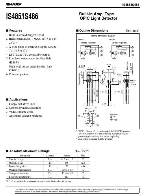
s Features 1. Built-in schmidt trigger circuit 2. High sensitivity(E V : MAX. 35rx at Ta=
25˚C ) 3. A wide range of operating supply voltage
Internal connection diagram
IS485 Voltage regulator
IS486 Voltage regulator
3 15kΩ
2
1
Amp.
3 15kΩ
2
1
Amp.
2.6 Gate burr 0.3 MAX.
uc2844中文资料
开关电源uc2844具有双列直插式8引脚封装;当前的脉冲宽度调制器的输入电压范围为5-30v,最大功耗= 1W,振荡器频率≥500KHz,参考电压= 5V,电压调节率= 6MV,电流调节率= 6mA,最大输出电流= 1000mA,最大占空比= 95%。
它包括振荡器,高增益误差放大器,锁存器,推挽输出电路等。
具有过压,过流检测保护功能。
UC2844引脚功能UC2844如何工作电源电路使用电流PWM 控制模式使反激电路形成稳定的双环反馈控制系统(输出直流电压隔离采样反馈外环和初级线圈励磁峰值电流采样反馈内环)。
控制系统通过开关电源的PWM调制器调整脉冲。
调整占空比以调整每个周期中前一个周期的占空比。
可以有效地调节初级线圈的输出电压和励磁峰值电流,以稳定输出电压。
反馈控制电路的主要特点是:当输入电压和负载电流变化较大时,动态响应速度更快,负载电流自动受到限制,补偿电路简单。
反激电路适用于低功率开关电源。
单端反激式开关电源的特性是开关管的周期性导通和截止。
当开关接通时,功率存储在变压器的初级线圈的一侧,并且连接到次级线圈的超快恢复二极管处于反向偏置状态,因此该二极管被切断并且没有电流流动通过变压器次级线圈,即没有能量传递到负载。
当开关断开时,变压器次级电感线圈中电压的极性反转,从而导通二极管并为输出电容器充电。
同时,有电流流过负载。
UC2844应用电路下图显示了为变频器设计的典型反激式开关电源电路,主要包括交流输入整流器电路,反激式开关功率级电路(由PWM控制器,MOS晶体管,变压器和整流二极管组成),RCD缓冲电路和反馈网络。
PWM控制芯片为uc2844。
UC2844是电流模式控制器。
它具有一个微调振荡器(可以精确控制占空比),一个用于温度补偿的参考基准,一个高增益误差放大器和一个电流采样比较器。
1-284540-2资料

1-284540-2 Product DetailsHome | Customer Support | Suppliers | Site Map | Privacy Policy | Browser Support© 2008 Tyco Electronics Corporation All Rights Reserved SearchProducts Documentation Resources My Account Customer SupportHome > Products > By Type > Terminal Blocks & Strips > Product Feature Selector > Product Details1-284540-2Active Terminal Block ConnectorsAlways EU RoHS/ELV Compliant (Statement of Compliance)Product Highlights:?Connector?Connector Type = Header?Shrouded?Housing Color = Green?Side StackableView all Features | Find SimilarProductsCheck Pricing &AvailabilitySearch for ToolingView MatingProducts (4)Product FeatureSelectorContact Us AboutThis ProductQuick LinksDocumentation & Additional InformationProduct Drawings:?TERMINAL BLOCK, HEADER ASSEMBLY 90° OPEN ENDS STACK...(PDF, English)Catalog Pages/Data Sheets:?None AvailableProduct Specifications:?None AvailableApplication Specifications:?Terminal Block Stacking Connectors(PDF, English)Instruction Sheets:?None AvailableCAD Files:?None AvailableList all Documents Additional Information:?Product Line InformationRelated Products:?Tooling?Mating Products (4)Product Features (Please use the Product Drawing for all design activity)Product Type Features:?Product Type = Connector?Connector Type = Header?Shrouded = Yes?Number of Positions = 12?Mount Angle = Right AngleElectrical Characteristics:?Current Rating, Max. (Amps.) = 11?Voltage (VAC) = 300Body Related Features:?Side Stackable = Yes?Number of Rows = Single?Centerline (mm [in]) = 3.50 [0.137]?Closed End = Without?Interlock = With?Flammability Rating = UL 94V-0?PCB Tail Length (mm [in]) = 3.40 [0.134] Contact Related Features:?Threaded Flange = Without?Screw Flange = Without?Contact Material = Phosphor Bronze?Contact Mating Area Plating = TinHousing Related Features:?Housing Color = Green?Housing Material = Polyamide 6.6Industry Standards:?RoHS/ELV Compliance = RoHS compliant, ELVcompliant?Lead Free Solder Processes = Wave soldercapable to 240°C, Wave solder capable to 260°C, Wave solder capable to 265°C?RoHS/ELV Compliance History = Always wasRoHS compliantOther:?Brand = BuchananProvide Website Feedback | Contact Customer Support。
ISPLSI2032-80LT48I资料

GLB on the device.
Copyright © 2002 Lattice Semiconductor Corp. All brand or product names are trademarks or registered trademarks of their respective holders. The specifications and information herein are subject to change without notice.
p Minimize Switching Noise is — Flexible Pin Placement
Description
The ispLSI 2032 and 2032A are High Density Programmable Logic Devices. The devices contain 32 Registers, 32 Universal I/O pins, two Dedicated Input Pins, three Dedicated Clock Input Pins, one dedicated Global OE input pin and a Global Routing Pool (GRP). The GRP provides complete interconnectivity between all of these elements. The ispLSI 2032 and 2032A feature 5V insystem programmability and in-system diagnostic capabilities. The ispLSI 2032 and 2032A offer nonvolatile reprogrammability of the logic, as well as the interconnect to provide truly reconfigurable systems.
- 1、下载文档前请自行甄别文档内容的完整性,平台不提供额外的编辑、内容补充、找答案等附加服务。
- 2、"仅部分预览"的文档,不可在线预览部分如存在完整性等问题,可反馈申请退款(可完整预览的文档不适用该条件!)。
- 3、如文档侵犯您的权益,请联系客服反馈,我们会尽快为您处理(人工客服工作时间:9:00-18:30)。
MDP0038
Coming Soon, ISL28148FIZ-T7 (Note 2)
178Z
6 Ld WLCSP (1.5mmx1.0mm)
W3x2.6C
Coming Soon, ISL28248FBZ (Note 1)
28248BZ
8 Ld SOIC
MDP0027
Coming Soon, ISL28248FBZ-T7* (Note 1)
Features
• 4.5MHz gain bandwidth product • 900µA supply current (per amplifier) • 1.8mV maximum offset voltage • 1pA typical input bias current • Down to 2.4V single supply operation • Rail-to-rail input and output • Enable pin (ISL28148 SOT-23 package only) • -40°C to +125°C operation • Pb-free (RoHS compliant)
2. These Intersil Pb-free WLCSP and BGA packaged products products employ special Pb-free material sets; molding compounds/die attach materials and SnAgCu - e1 solder ball terminals, which are RoHS compliant and compatible with both SnPb and Pb-free soldering operations. Intersil Pb-free WLCSP and BGA packaged products are MSL classified at Pb-free peak reflow temperatures that meet or exceed the Pb-free requirements of IPC/JEDEC J STD-020.
PART NUMBER
PART MARKING
PACKAGE (Pb-free)
PKG. DWG. #
ISL28148FHZ-T7* (Note 1)
GABT
6 Ld SOT-23 (Tape and Reel)
MDP0038
ISL28148FHZ-T7A* (Note 1)
GABT
6 Ld SOT-23 (Tape and Reel)
ISL28148, ISL28248, ISL28448
Absolute Maximum Ratings (TA = +25°C)
Supply Voltage . . . . . . . . . . . . . . . . . . . . . . . . . . . . . . . . . . . . . 5.75V Supply Turn On Voltage Slew Rate . . . . . . . . . . . . . . . . . . . . . 1V/μs Differential Input Current . . . . . . . . . . . . . . . . . . . . . . . . . . . . . . 5mA Differential Input Voltage . . . . . . . . . . . . . . . . . . . . . . . . . . . . . . 0.5V Input Voltage . . . . . . . . . . . . . . . . . . . . . . . . . V- - 0.5V to V+ + 0.5V ESD Rating
1
CAUTION: These devices are sensitive to electrostatic discharge; follow proper IC Handling Procedures.
1-888-INTERSIL or 1-888-468-3774 | Intersil (and design) is a registered trademark of Intersil Americas Inc.
Thermal Information
Thermal Resistance (Typical, Note 3)
θJA (°C/W)
6 Ld SOT-23 Package . . . . . . . . . . . . . . . . . . . . . . .
230
6 Ld WLCSP Package . . . . . . . . . . . . . . . . . . . . . . .
Applications
• Low-end audio • 4mA to 20mA current loops • Medical devices • Sensor amplifiers • ADC buffers • DAC output amplifiers
Ordering Information
The ISL28148, ISL28248 and ISL28448 are 4.5MHz low-power single, dual and quad operational amplifiers. The parts are optimized for single supply operation from 2.4V to 5.5V, allowing operation from one lithium cell or two Ni-Cd batteries.
Copyright © Intersil Americas Inc. 2007, 2008. All Rights Reserved.
All other trademarks mentioned are the property of their respective owners.
元器件交易网
MDP0043
Coming Soon, ISL28448FVZ (Note 1)
MXZ
14 Ld TSSOP
MDP0044
Coming Soon, ISL28448FVZ-T7* (Note 1)
MXZ
14 Ld TSSOP (Tape and Reel)
MDP0044
*Please refer to TB347 for details on reel specifications. NOTES:
The parts draw minimal supply current (900µA per amplifier) while meeting excellent DC accuracy, AC performance, noise and output drive specifications. The ISL28148 features an enable pin that can be used to turn the device off and reduce the supply current to a maximum of 16µA. Operation is guaranteed over -40°C to +125°C temperature range.
1. These Intersil Pb-free plastic packaged products employ special Pb-free material sets; molding compounds/die attach materials and 100% matte tin plate PLUS ANNEAL - e3 termination finish, which is RoHS compliant and compatible with both SnPb and Pb-free soldering operations. Intersil Pb-free products are MSL classified at Pb-free peak reflow temperatures that meet or exceed the Pb-free requirements of IPC/JEDEC J STD-020.
Pinouts
ISL28148, ISL28248, ISL28448
ISL28148 (6 LD SOT-23)
TOP VIEW
OUT 1
V- 2 +-
IN+ 3
6 V+ 5 EN 4 IN-
ISL28148
(6 LD WLCSP)
TOP VIEW
1
2
A
NC
OUT
B
V+
V-
C
IN -
IN +
ISL28248 (8 LD SOIC) TOP VIEW
130
8 Ld SO Package . . . . . . . . . . . . . . . . . . . . . . . . . . .
TOP VIEW
OUT_A 1 IN-_A 2 IN+_A 3 V+ 4 IN+_B 5 IN-_B 6
